

Wohler AMP1-VSD User Manual

AMP1-VSD
1U Digital Audio Speaker Monitors
with One SDI Input and One SDI Output on BNC,
Two AES Inputs on BNC, Two AES Outputs From SDI
Input on BNC, Two Analog Outputs of the Left/Right Channel
Selections on XLR, Four Analog Outputs From Selected
Digital Source, Summable Channel Assignment,
Four 26-Segment Level Meters, and Phase Indication
Document P/N 821615 Rev-A
User Manual
CONTENTS
Title and Contents .............................................................
Introduction ...............................................................................
Section 1: Features, Specs, and Installation ...........
Description and Features .............................................................
Applications and Specifications ...................................................
Installation .................................................................................
Section 2: Operation ........................................................
Front Panel Features ...................................................................
Rear Panel Features ....................................................................
Audio Amplifier and Speaker Configuration ................................
Section 3: Technical Information ................................
General Technical Observations ..................................................
AES to Analog Converter Module (919050 PCB) .........................
AES D/A Gain Calibration Fine Adjustment (919050 PCB) .......
AES Error Indication Jumper Locations (919050 PCB) .................
1
2
3
4
5
6
7
8
12
16
17
18
19
20
21
SDI to AES Converter Module (919096 PCB) ..............................
Level Meter Rear Panel 6-Position DIP Switch Settings ................
Level Meter Internal 10-Position DIP Switch Settings ..................
Level Meter DIP Switch Locations (919174 PCB) .........................
Level Meter Alternative Scales ....................................................
AMP1-VSD Interconnect Block Diagram .....................................
© 2004 Wohler Technologies Inc. ALL rights reserved
22
23
24
25
26
27
ECO-2784 (11/17/04)
1

Important Safety Instructions
1) Read these instructions.
2) Keep these instructions.
3) Heed all warnings.
4) Follow all instructions.
5) Do not use this apparatus near water.
6) Clean only with dry cloth.
7) Do not block any ventilation openings. Install in accordance with the manufacturer's instructions.
8) Do not install near any heat source such as radiators, heat registers, stoves, or other apparatus (including
amplifiers) that produce heat.
9) Do not defeat the safety purpose of the polarized or grounding-type plug. A polarized plug has two blades
with one wider than the other. A grounding type plug has two blades and a third grounding prong. The
wide blade or the third prong are provided for your safety. If the provided plug does not fit into your outlet,
consult an electrician for replacement of the obsolete outlet.
10) Protect the power cord from being walked on or pinched, particularly at plugs convenience receptacles
and the point where they exit from the apparatus.
11) Only use attachments/accessories specified by the manufacturer.
12) Use only with the cart stand, tripod, bracket, or table specified by the manufacturer, or sold with the
apparatus. When a cart is used, use caution when moving the cart/apparatus combination to avoid injury
from tip-over.
13) Unplug this apparatus during lightning storms or when unused for long periods of time.
14) Refer all servicing to qualified service personnel. Servicing is required when the apparatus has been
damaged in any way, such as when power-supply cord or plug is damaged, liquid has been spilled or
objects have fallen into the apparatus, the apparatus has been exposed to rain or moisture, does not
operate normally, or has been dropped.
15) Do not expose this apparatus to rain or moisture.
16) The apparatus shall be connected to a mains socket outlet with a protective earthing connection.
CAUTION!
In products featuring an audio amplifier and speakers, the surface at the side of the
unit, where the audio amplifier heat sink is internally attached, may get very hot after
extended operation. When operating the unit excercise caution when touching this
surface and ensure that external materials which may be adversely affected by heat
are not in contact with it. There is a Hot Surface label (see diagram) attached to the
aforementioned surface of the product.
Introduction
Congratulations on your selection of a Wohler Technologies product. We are confident it represents the best performance and value
available, and we guarantee your satisfaction with it.
If you have questions or comments you may contact us at:
Phone: (510) 870-0810 Fax: (510) 870-0811
www.wohler.com support@wohler.com
2
© 2007 Wohler Technologies, Inc. ALL rights reserved
Wohler Technologies, Inc.
31055 Huntwood Avenue
Hayward, CA 94544
US Toll-Free: 1-888-596-4537

AMP1-VSD User Manual P/N 821615, Rev-A
Features, Specs, and Installation
Sect. 1: General Features and Specifications
Section 1
Description
Features
Applications
Specifications
Installation
© 2004 Wohler Technologies Inc. ALL rights reserved
3
AMP1-VSD User Manual P/N 821615, Rev-A
Section 1: Features , Specs, and Installation
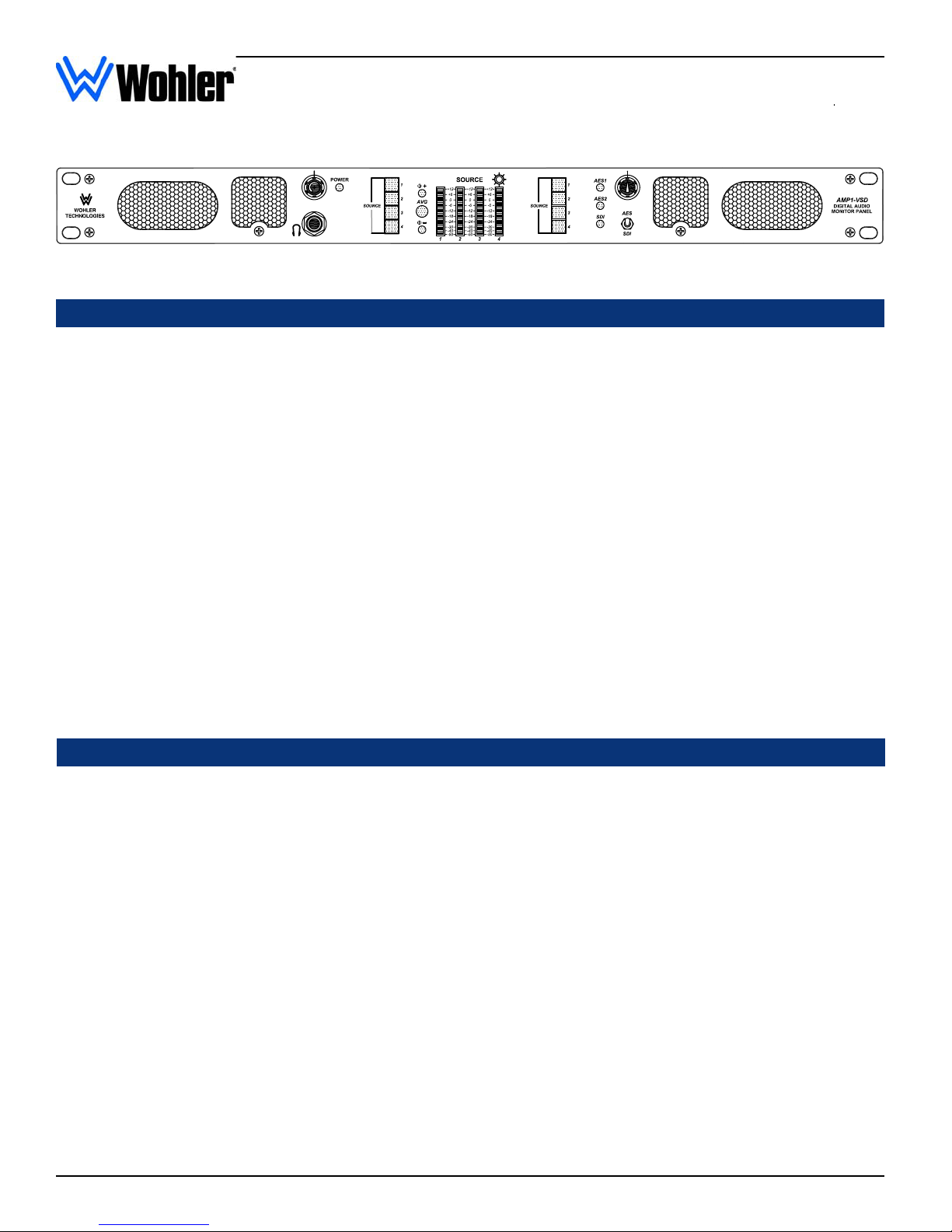
AMP1-VSD
Powered Digital Audio Monitors
AMP1-VSD Front Panel
Description
The rackmountable 1U size AMP1-VSD audio monitor is capable of audibly monitoring up to four audio source channels through
its stereo speaker system while simultaneously visually monitoring the audio levels via four high-resolution 26-segment LED
bargraph level meters. The AMP1-VSD monitors digital SDI and AES audio sources. A toggle switch on the front panel allows
selection between AES or SDI input sources.Two banks of four buttons on the front panel are used to independently assign from
one to four (summed) channels to each of the two (left and right) speaker channels. SDI signal status is indicated by one bi-color
(red/green) LED and AES signal status is indicated by two bi-color (red/green) LEDs. Wohler Technologies proprietary three-LED
stereo phase indication feature allows monitoring of phase relationships between the left and right speaker channels. Other features
include separate volume and balance controls, power indication LED, and headphone output. Output limiter circuits are incorporated
to protect the speakers, and extensive magnetic shielding allows placement immediately adjacent to video monitors with no color
impurities.
The rear panel of the AMP1-VSD features one SDI input and one SDI output on unbalanced BNC connectors, two AES outputs
(de-embedded from the SDI source) on two BNC connectors, two AES inputs on BNC connectors, four analog outputs (deembedded from the selected digital source) on four Phoenix connectors, and left and right analog outputs (of the channels
assigned to the left and right speakers) on two balanced XLR connectors.
All AMP1 Series units contain three audiophile-quality drivers and three power amplifiers; two amplifiers (and two speakers) that
reproduce midrange and high frequency information in stereo, and a third amp/driver combination (and two speakers) that handles
summed Low Frequency (LF) information below the 500 Hz crossover point. The AMP1 Series unique audio design has two
important advantages. First, it provides optimally focused sound in an Ultra Near Field
higher SPL for the operator while reducing overall ambient sound and adjacent bay crosstalk. Second, electronic rather than
acoustic cancellation of bass frequencies provides positive audible detection of reversed polarity (“out of phase”) audio feeds.
tm
(1 to 3 feet) environment. This allows
Features
• 98 dB SPL at two feet
• Only one rack space high
• Excellent high frequency response for positive detection of
background whine and noise
• Audible and visual indication of phase/polarity problems
• Thorough magnetic shielding for placement next to video
monitors
• Four 26-segment high-resolution tri-color bargraph level meters:
-Selectable Input Referrence Level (0, +4, +6, or +8 dBu)
-Selectable Display Mode (VU Only, VU/PPM, or PPM Only)
-Selectable Peak Hold (Manual, 3-Second, 10-Second, or Off)
-Selectable PPM Ballistics (Type I, Type II, DIN 45406, or
SSRT)
-Selectable alternate Bargraph Scales (Extended VU, VU,
BBC, NORDIC, DIN, or Custom)
• Two banks of four push buttons for assigning single or
summed channels to the left and right speaker
• Headphone output
• Power indication LED
• One SDI input and one SDI re-clocked output on unbalanced
BNC connectors
• Two AES inputs on two unbalanced BNC connectors
• Two AES outputs (converted from the SDI source) on two
BNC connectors
• Four analog outputs (converted from the selected digital
source) on four Phoenix connectors
• Analog outputs (of the sources selected for speaker
monitoring) on two balanced XLR connectors
• One SDI signal status indication LED
• Two AES signal status indication LEDs
• Quick and easy installation: simply slide in the rack and
connect audio and AC power
• Numerous control and input options
4
© 2004 Wohler Technologies Inc. ALL rights reserved
AMP1-VSD User Manual P/N 821615, Rev-A Section 1: Features , Specs, and Installation
Applications
The AMP1-VSD is ideally suited for use in VTR bays, mobile production vehicles, teleconferencing installations, multimedia systems,
satellite links and cable TV facilities, and on-air radio studios. Designed and manufactured in the U.S., the AMP1-VSD is backed by a
strong warranty and a satisfaction guaranteed return policy.
General Specifications
AES Input Connectors:
SDI Input Connectors:
AES Input impedance:
SDI Input impedance:
Input Level for Maximum
Output (Volume Full On):
Input Overload:
Peak Acoustic Output
(@ 2 ft.):
Response, Sixth Octave:
Power output
ΩΩ
Ω):
ΩΩ
ΩΩ
Ω):
ΩΩ
RMS Each Side (4
RMS Bass (4
Distortion, Electrical:
Distortion, Acoustic:
BNC, 2 each
BNC, 1 each
75 Ω, unbalanced
75 Ω, unbalanced
0 dBv balanced
+26 dBv balanced
98 dB SPL
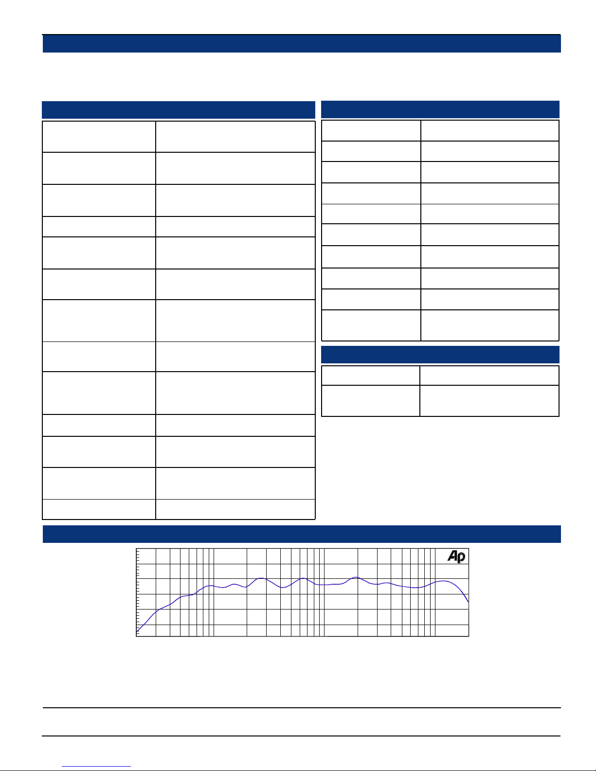
80 Hz - 16 kHz ± 7 dB)
(-10 dB @ 50 Hz, 22 kHZ)
10 W transient / 5 W continuous
20 W transient / 10 W continuous
Less than 0.15% at any level below
limit threshold
8% or less at worst case frequencies
above 180 Hz including cabinet
resonance; typically less than 2%
Level Meter Specifications
Level Meter Type:
Bargraph Quantity:
LED Color:
Metering Range:
Reference Level:
Display Mode Select:
Peak Hold Select:
PPM Ballistics Select:
Calibration:
Scale Select:
Physical Specifications
Weight:
Dimensions (HxWxD):
26-segment tri-color LED bargraph
4 each, vertical
Tricolor (red, amber, green)
62 dB
0, +4, +6, or +8 dBv selectable
VU Only, VU/PPM, or PPM Only
Manual, 3-sec, 10-sec, or OFF
Type I, Type II, DIN 4506, or SSRT
Auto
VU, Extended VU, BBC, NORDIC,
DIN, or Custom
10 lbs. (4.53 kg)
3.5 x 19 x 12 inches
(89 x 483 x 305 mm)
Hum and Noise:
Magnetic Shielding:
Power Consumption
(Average Maximum):
AC Mains input:
+10
d
B
Custom combinations of connectors, controls and level meters are available by special order.
-10
-20
-30
Better than -68 dB below full output
Less than 1 Gauss any adjacent
surface
35 W
100-240VAC, 50-60 Hz
For AES specifications see page 19.
For SDI specifications see page 22.
Audio Response Curve
0
2k1k50020010050 20k20
Hz
Typical 1/6 Octave Audio Response Curve
5k
10k
Units are designed to meet, at time of manufacture, all currently applicable product safety and EMC requirements, such as those of
CE. 0 dbV ref. 0.775V RMS. Features and specifications subject to improvement without notice.
© 2004 Wohler Technologies Inc. ALL rights reserved
5

AMP1-VSD User Manual P/N 821615, Rev-A
Section 1: Features , Specs, and Installation
Installation
Mounting
The unit should be mounted where convenient for operating persons, ideally at approximately ear/eye level for best high frequency
response and visual observation of the level meters. Its superior magnetic shielding eliminates concerns about locating it adjacent
to most types of CRT monitors, including high-resolution color monitors.
Heat Dissipation
Heat dissipated by the speaker amps is conducted directly to the left side of the chassis; no special considerations for cooling are
necessary as long as the ambient temperature inside the rack area does not exceed approximately 40°C (104°F).
Sympathetic Vibration
Sympathetic vibration from other equipment (cables, etc.,) in the rack may be serious enough to interfere with the unit’s sound
quality out in the listening area. The use of thin card stock and/or felt or foam weather-stripping type materials between adjacent
vibrating surfaces, or tying up loose cables, etc., may be required to stop vibrations external to the unit.
Mechanical Bracing
Even though the unit is fairly heavy, the chassis is securely attached to the front panel at eight points along its surface, not just at
the four corners of the chassis ears. This feature will reduce or eliminate rear bracing requirements in many mobile/portable
applications. The weight of internal components is distributed fairly evenly around the unit.
Audio Connections
Connection of the audio feeds is straightforward. Please refer to the system interconnect block diagram on page 27 for clarification of the general signal paths into and out of the AMP1-VSD unit.
Care should be exercised to avoid mismatched cable types and other similar causes of undesired reflections in RF signal systems.
If severe enough, such reflections can result in corruption of the digital datastream.
AC Power
The unit's AC mains connection is via a standard IEC inlet, with safety ground connected directly to the unit's chassis. The
universal AC input (100-240VAC, 50/60Hz) switching power supply is a self-resetting sealed type, with automatic over-voltage
and over-current shutdown. There is no user-replaceable fuse in either the primary or secondary circuit.
6
© 2004 Wohler Technologies Inc. ALL rights reserved

AMP1-VSD User Manual P/N 821615, Rev-A
Audio Amplifier and Speaker Configuration
Balance Control Characteristics
Section 2
Operation
Front Panel Features
Rear Panel Features
© 2004 Wohler Technologies Inc. ALL rights reserved
7

AMP1-VSD User Manual P/N 821615, Rev-A
Section 2: Operation
Front Panel Features
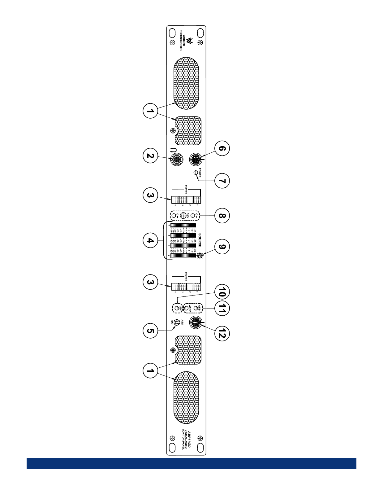
Please refer to Figure-2a on the facing page to familiarize yourself with the front panel features of the AMP1-VSD unit. The following
sections describe these features and are referenced, by number, to Figure-2a.
Speakers
1
The AMP1-VSD features two mid-range speakers (left and right) and two woofer speakers. Two amplifier/driver combinations
handle midrange and high frequency information in the left and right (stereo) speaker channels, while the third channel
reproduces and sums the left and right channel information below the 500 Hz crossover point in the two woofer (bass)
speakers. Note that the woofer channel is NOT a dedicated LFE (subwoofer) or Center channel. See page 16 for more
information concerning the AMP1 Series audio amplifier/speaker configuration.
Headphone Jack
2
This jack accepts a standard 1/4” phone type stereo plug. When you plug in headphones, the internal speakers will mute.
Speaker Assign Channel Buttons (Left and Right)
3
Use the left bank of four buttons to assign one to four of the four available channels for monitoring from the left
speaker channel. Use the right bank of four buttons to assign one to four of the four available channels for monitoring
from the right speaker channel. Channel buttons toggle On/Off and will light up BLUE to indicate they are selected.
Operation for channel selection for each bank of four buttons is as follows:
Single Channel Select: Press and release a single channel button to select that channel (and deselect any previous
selection). Pressing and releasing the selected channel button again will deselect it.
Multi-Channel Select (Summing): Press and hold down a desired channel button, then press other channel
buttons to add (sum) additional channels (or press any again to deselect). Release all buttons to accept the selection
set. When multiple channels are selected, pressing and holding an already selected channel button will allow
further modification to the selection set. Releasing all buttons accepts the new selection set. Pressing and
immediately releasing an already selected channel button will select only it and deselect all other channel selections.
Note that if channels assigned to either the left or right level meters are multi-channel (summed), then the respective
level meter will indicate summed audio levels.
If the user presses a previously selected (lighted) channel button, but then decides not to make any changes to the
selection set, the user should keep the button depressed for at least 1.5 seconds before releasing it. This will preserve
the current selection set as though the button was never pushed.
Audio Level Meter LED Bargraph Displays (1-4)
4
Audio levels for the four source channels are displayed via these four tri-color LED bargraph meters. All bargraph LED
segments are of the tri-color type (green, amber, red) and the meters are user adjustable for Reference Level, Display
Mode, Peak Hold, PPM Ballistics, Alternate Bargraph Scales, and Phase Correlation via DIP switches on the rear
panel and inside the unit. For factory set and user adjustable level meter DIP switch settings, see pages 23 and 24. For
meter specifications, see page 5.
AES/SDI Source Select Switch
5
This two position toggle switch selects between the two primary input sources; AES or SDI. When this toggle switch is set
to AES, the unit will monitor the AES source signals as input on the rear panel AES IN BNC connectors (Item F, page 12).
When this toggle switch is set to SDI, the unit will monitor the SDI source signals as input on the rear panel SDI IN BNC
connector (Item C, page 12).
Volume Control Pot
6
This controls the loudness of the audio reproduced by the internal speakers or connected headphone. Clock-wise
rotation of this control increases the loudness of the monitored audio in the speakers or headphones.
Power LED
7
This LED glows GREEN to indicate the unit is connected to mains power and an operation voltage is present.
8
© 2004 Wohler Technologies Inc. ALL rights reserved
(Continued)
AMP1-VSD User Manual P/N 821615, Rev-A Section 2: Operation
Figure-2a: Front Panel Features
© 2004 Wohler Technologies Inc. ALL rights reserved
9
 Loading...