

Wohler AMP1-MADIe User Manual

AMP1-MADIe
1RU, 8 of 64 Channel, MADI Audio
Monitor
User Guide
(Software Release: V1.0x)
Part Number 821091, Revision B

© 2012 Wohler Technologies, Inc. All rights reserved.
This publication is protected by federal copyright law. No part of this publication may be
copied or distributed, stored in a retrieval system, or translated into any human or computer
language in any form or by any means electronic, mechanical, manual, magnetic, or otherwise,
or disclosed to third parties without the express written permission of Wohler Technologies.
Reproduction
Licensed users and authorized distributors of Wohler Technologies, Inc. products may copy
this document for use with Wohler Technologies., Inc. products provided that the copyright
notice above is included in all reproductions.
Customer Support
Wohler Technologies, Inc.
31055 Huntwood Avenue
Hayward, CA 94544
www.wohler.com
Phone: 510-870-0810
FAX: 510-870-0811
US Toll Free: 1-888-596-4537
(1-888-5-WOHLER)
Web: www.wohler.com
Sales: sales@wohler.com
Support: support@wohler.com
Disclaimers
Even though Wohler Technologies, Inc. has tested its equipment and software, and reviewed
the documentation, Wohler Technologies, Inc. makes no warranty or representation, either
express or implied, with respect to software, documentation, their quality, performance,
merchantability, or fitness for a particular purpose.
In no event will Wohler Technologies, Inc. be liable for direct, indirect, special, incidental, or
consequential damages resulting from any defect in the hardware, software, or its
documentation, even if advised of the possibility of such damages.
Some states do not allow the exclusion or limitation for incidental or consequential damages, so
the above exclusion or limitation may not apply to you.
Printing
This document is intended to be printed on a duplex printer, such that the copy appears on
both sides of each page. This ensures that all new chapters start on a right-facing page.
This document looks best when printed on a color printer since some images may be indistinct
when printed on a black and white printer.
PDF
All text strings appearing in this shade of blue are hyperlinks.
Other Technologies and Products
Microsoft Windows, and Internet Explorer are registered trademarks of Microsoft Corporation.
Last Update
October 22, 2012
821091: AMP1-MADIe User Guide
ii
© 2012 Wohler Technologies, Inc. All rights reserved.

Table of Contents
Chapter 1. Installation . . . . . . . . . . . . . . . . . . . . . . . . . . . .1
Introduction ...................................................................1
Overview..................................................................1
Topics......................................................................1
Safety ...........................................................................2
Instructions..............................................................2
Safety Symbols ........................................................3
Mounting..................................................................3
Heat Dissipation........................................................3
Sympathetic Vibration................................................3
Mechanical Bracing....................................................4
Electrical Interference ................................................4
Power ......................................................................4
Compliance ....................................................................4
FCC.........................................................................4
ICES-003 .................................................................5
Front Panel.....................................................................5
Rear Panel......................................................................7
Main Screen ...................................................................8
Chapter 2. Operation. . . . . . . . . . . . . . . . . . . . . . . . . . . . .11
Introduction .................................................................11
Overview................................................................11
Topics....................................................................11
Initial Operation............................................................12
Monitor Channel Selection ..............................................12
Selecting Different Channels for Monitoring.......................13
821091: AMP1-MADIe User Guide
© 2012 Wohler Technologies, Inc. All rights reserved.
iii

Default Presets........................................................13
Selecting Any Eight Channels ....................................14
Adjusting the Volume of Each Channel..............................15
Adjusting the Speaker Audio Tone Controls .......................15
Selecting the Multimode Optical Input ..............................16
Using the Balanced Analog Outputs..................................17
Pre Fade or Post Fade Metering........................................18
Saving Your Settings......................................................19
USB Port Functionality....................................................20
Copying a Configuration to the AMP1-MADIe ...............20
Copying a Configuration File from the AMP1-MADIe......21
Chapter 3. AMP1-MADIe Graphical User Interface
(GUI) Manager . . . . . . . . . . . . . . . . . . . . . . . . 23
Introduction..................................................................23
Overview................................................................23
Topics ....................................................................23
Running the AMP1-MADIe Manager..................................24
Activity Log and Setup Files ............................................24
The Channels Tab ..........................................................25
The Preset Tabs.............................................................26
Preset Name and Control Area...................................26
Monitoring Positions (1 through 8) .............................26
Channel Volume dB..................................................27
The Current Tab ............................................................27
The Facility Tab .............................................................28
The Options Tab ............................................................29
Level Meters ...........................................................30
Metering Mode ........................................................30
Speaker Mute..........................................................30
Input Selection........................................................31
Screen Brightness....................................................31
821091: AMP1-MADIe User Guide
iv
© 2012 Wohler Technologies, Inc. All rights reserved.

Analog Output.........................................................31
Audio Delay............................................................32
Functions Enabled ...................................................32
Tone Controls..........................................................32
Channel Knob Acceleration........................................32
Menu Lockout Override ..................................................33
The Ethernet Tab...........................................................34
File Update Options .................................................34
Documentation........................................................35
The USB Tab.................................................................35
Using a Flash Drive..................................................35
Flash Drive Files......................................................36
Chapter 4. Internal Menu System . . . . . . . . . . . . . . . . . . .37
Introduction .................................................................37
Overview................................................................37
Topics....................................................................37
Menu Navigation Overview .............................................38
Audio Menu 1 ...............................................................39
Audio Menu 2 ...............................................................40
Options Menu ...............................................................41
Meter Type and Reference Menu......................................42
Meter Segment Menu.....................................................43
Version and Ethernet Menu.............................................44
Chapter 5. Features and Specifications. . . . . . . . . . . . . . .47
Introduction .................................................................47
Overview................................................................47
Topics....................................................................47
Features ......................................................................48
Specifications ...............................................................49
Technical Functional Overview.........................................50
821091: AMP1-MADIe User Guide
© 2012 Wohler Technologies, Inc. All rights reserved.
v

Appendix A. Connecting the AMP1-MADIe to a LAN. . . . . 53
Introduction..................................................................53
Overview................................................................53
Topics ....................................................................53
Requirements ...............................................................54
Downloading the Installation File .....................................54
Installing the AMP1-MADIe Manager ................................55
Launching the AMP1-MADIe Manager ...............................56
Adding Your AMP1-MADIe to Your Network .......................57
Disconnecting From an AMP1-MADIe................................60
Appendix B. Software Upgrades. . . . . . . . . . . . . . . . . . . . 61
Introduction..................................................................61
Overview................................................................61
Topics ....................................................................61
Checking for Updates.....................................................62
Upgrading the AMP1-MADIe............................................63
821091: AMP1-MADIe User Guide
vi
© 2012 Wohler Technologies, Inc. All rights reserved.

Introduction
Overview
The AMP1-MADIe is a 1RU, eight of 64 channel MADI audio monitor.
This unit comes with two 2.4” graphics screens that display eight
channels of audio level metering. Any eight channels in the MADI
stream may be audibly and visually monitored. The AMP1-MADIe is
small, low-cost, and simple to operate. Its setup configuration can
easily be copied to other AMP1-MADIe units.
CHAPTER 1
Installation
Topics
Note that very little configuration should be necessary. We have
already configured the unit to the most commonly requested settings.
However, should you need to change these settings, you can access the
unit either through the front panel menu system, or remotely through a
PC graphical user interface (GUI).
Topics Page
Safety 2
Compliance 4
Front Panel 5
Rear Panel 7
Main Screen 8
821091: AMP1-MADIe User Guide
© 2012 Wohler Technologies, Inc. All rights reserved.
1

Chapter 1 Installation
Safety
Safety
Instructions
1. Read, keep, and follow all of these instructions; heed all warnings.
2. Do not use this equipment near water.
3. Use only a dry cloth to clean the equipment.
4. Do not block any ventilation openings.
5. Do not install near any heat source such as a radiator, heat register,
amplifier, or stove.
6. Do not attempt to plug the unit into a two-blade outlet (with only
two prongs of equal width).
IMPORTANT:
By design, this monitor will only plug into a three-prong outlet for
your safety. If the plug does not fit into your outlet, contact an
electrician to replace the obsolete outlet.
7. Protect the power cord from being walked on or pinched,
particularly at plug’s source on the equipment and at the socket.
8. Use only the attachments/accessories specified by the
manufacturer.
9. Unplug the equipment during lightning storms or when unused
for long periods of time.
10. Refer all servicing to qualified service personnel. Servicing will be
required under all of the following conditions:
• The equipment has been damaged in any way, such as when
the power-supply cord or plug is damaged.
• Liquid had been spilled or objects have fallen onto the
equipment.
• The equipment has been exposed to rain or moisture.
• The equipment does not operate normally.
• The equipment has been dropped.
821091: AMP1-MADIe User Guide
2
© 2012 Wohler Technologies, Inc. All rights reserved.
Safety Symbols
Chapter 1 Installation
Safety
WARNING:
Mounting
The symbol to the left warns of electric shock hazard inside the unit.
Disconnect the power cord before removing access panels when
installing upgrades. Only qualified service personnel are to operate the
equipment with covers removed, and are to exercise caution to avoid
personal injury.
The unit is designed for a standard 19" rack. Install it at ear/eye level
for best high frequency response and visual observation of the display
screens. Please adhere to the following clearances:
Clearance Surface
24” Front
3” Rear
2” Sides
1.75” Top and Bottom (if either radiates heat)
0” Top and Bottom (if no heat)
Heat Dissipation
The ambient temperature inside the mounting enclosure should not
exceed 40° Celsius (104° Fahrenheit). Adjacent devices can be rack
mounted (or stacked) in proximity to the unit if this temperature is not
exceeded. Otherwise, allow a 1RU (1.75”/44.45mm) space above and
below the unit for air circulation.
Important:
To reduce noise, the monitor does not have any fans. As a result, the
heat generated by the class D power amplifiers, power supplies, and
other components is vented by slots in the sides and back of the unit.
Therefore, as a safety precaution, you must allow proper ventilation on
these surfaces.
Sympathetic Vibration
Sympathetic vibration from other equipment (cables, etc.,) in the rack
may be serious enough to interfere with the unit’s sound quality. If you
experience sympathetic vibrations, use thin card stock, felt, foam, or
821091: AMP1-MADIe User Guide
© 2012 Wohler Technologies, Inc. All rights reserved.
3

Chapter 1 Installation
Compliance
weather-stripping between the vibrating surfaces. Tie loose cables
securely with cable ties.
Mechanical Bracing
The 1RU chassis is securely attached to the front panel. In addition, the
chassis has mounting tabs through which you attach it to the rack rail.
This feature will reduce or eliminate rear bracing requirements in many
mobile/portable applications. The weight of internal components is
distributed fairly evenly around the unit.
Electrical Interference
Be careful to avoid mismatched cable types and other similar causes of
undesired reflections in digital signal systems. If severe enough, such
reflections can result in corruption of the digital data stream. As with
any audio equipment, maximum immunity from electrical interference
requires the use of shielded cable; however, satisfactory results can
sometimes be obtained without it. The internal circuitry ground is
connected to the chassis.
Power
The unit comes with a standard internal power supply and connects an
A/C mains power source (60W, 100 to 240 VAC, ±10%, 50/60Hz)
through the IEC connector provided on the rear panel of the unit.
When the mains plug or appliance coupler is used as the disconnect
device, the disconnect device should remain operable.
Compliance
FCC
This equipment has been tested and found to comply with the limits for
a Class A digital device, pursuant to part 15 of the FCC Rules. These
limits are designed to provide reasonable protection against harmful
interference when the equipment is operated in a commercial
environment. This equipment generates, uses, and can radiate radio
821091: AMP1-MADIe User Guide
4
© 2012 Wohler Technologies, Inc. All rights reserved.

frequency energy and, if not installed and used in accordance with the
MADIe
Wohler
8
1
2
3
4
5
6
7
CHAN
ASSIGN
POWER
BALANCE
MASTER
VOLUME
CHANNEL
VOLUME
PRESS & HOLD FOR MENU
SELECT
PRESET
PCR1-AD
Bob
31
64
-60 -50 -40 -30 -20 -10 0
PCR1-GFX
Phil
PCR3-
PGM
1
2
PCR2-DIR
Bucky
MUTED
5
23
11
17
REM-24
NVG/NYJ
ANNC-12
Costas
TAPE-SUP
Dave
REM-12
LONDON
Preset 1: Master Control
-60 -50 -40 -30 -20 -10 0
MUTED
Unit Name
Post Fade
Metering
Speakers
Headphones
Master Volume Balance
Power
Channel Select Buttons
Metering Screens
Select Preset
USB
Channel Volume
Channel Assign
instruction manual, may cause harmful interference to radio
communications. Operation of this equipment in a residential area is
likely to cause harmful interference, in which case the user will be
required to correct the interference at his own expense.
ICES-003
This Class A digital apparatus complies with Canadian ICES-003.
Cet appareil numérique de la classe A est conforme à la norme
NMB-003 du Canada.
Front Panel
Chapter 1 Installation
Front Panel
Figure 1–1 Front Panel Layout
• Speakers: Audio monitoring is achieved through the use of class D
amplifiers driving two (left/right) wide range speakers.
• Headphone Jack (1/4”): A 1/4" jack for an optional headphone is
provided on the front panel.
• USB 2.0 Port: This USB Type A connector allows you to use a flash
drive (not supplied) to copy system configurations to another
AMP1-MADIe or to a PC.
• Master Volume: The left knob controls the Volume of the internal
speakers, headphones, and optionally the rear panel balanced
analog outputs.
821091: AMP1-MADIe User Guide
© 2012 Wohler Technologies, Inc. All rights reserved.
5
Chapter 1 Installation
Front Panel
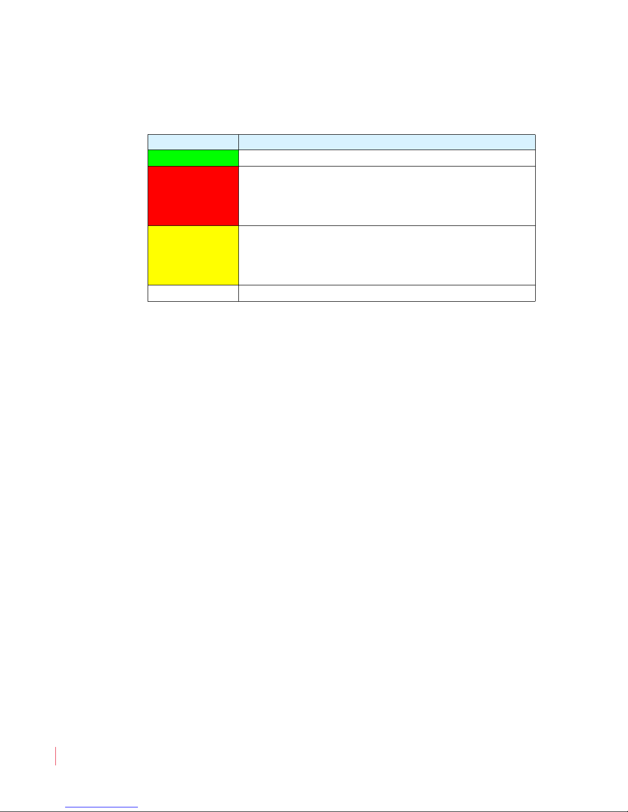
• Power Indicator: This tri-color LED indicates power and basic
status information. See Table 1–1 below.
Table 1–1 Power Color/Indication Descriptions
LED Color Description
Green The AMP1-MADIe is functioning normally.
Red
When the LED flashes green or yellow followed by a
series of red flashes, each flash sequence indicates an
error code. Try restarting the unit, and if the problem
persists, contact Wohler Technical Support.
The LED is also a solid yellow when it is booting.
Yellow
The LED blinks yellow when a firmware update is in
progress.
Off The AMP1-MADIe is not receiving AC power.
• Metering: These screens display bar graphs and the configuration
menus.
• Channel Select Buttons: Used in conjunction with the
Volume
knob, these eight buttons allow you to select the audio
Channel
channels you want to monitor or adjust their individual volume
level. These buttons can be named via the Ethernet connection using
the PC GUI software. They are also used in conjunction with the
internal menu system.
• Balance: The right knob adjusts the Balance between the speakers,
headphones, and optionally between the rear panel balanced analog
outputs.
• Select Preset: Presets are complete configurations of monitoring
channels, including individual channel volume levels. Pressing this
button displays the
Preset Selection Menu.
• Channel Assign: Pressing this button displays the
Assignment Menu
64) MADI channels you want to monitor. Note that the channels
you monitor need not be contiguous.
• Channel Volume: After the
to highlight the monitoring channels in yellow, the yellow Channel
Volume
Pressing the yellow
yellow highlighted channels.
821091: AMP1-MADIe User Guide
6
© 2012 Wohler Technologies, Inc. All rights reserved.
Channel
in which you can select the exact eight (of the
Channel Select buttons are pressed
adjusts the individual level of each highlighted channel.
Channel Volume mutes or unmutes the
Rear Panel
RIGHTLEFT MONO MIX
BALANCED
ANALOG OUT
MADI
IN OUT
100-240 VAC
50/60 Hz
MADI
OUT IN
ETHERNET
Power
Ethernet
MADI I/O 1 and 2
(Inputs and Outputs)
Analog Audio Outputs
(Left, Mono Mix, & Right)
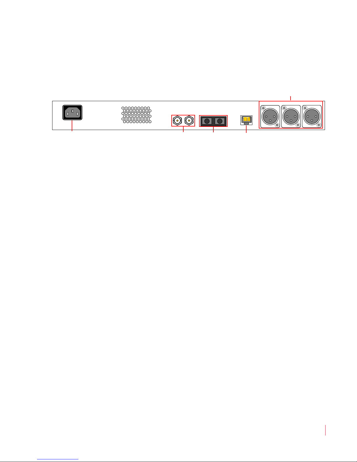
Figure 1–2 Rear Panel Layout
• Power: The AMP1-MADIe uses a standard IEC power cord for the
100 to 240 VAC ±10%, 50/60 Hz power connection.
• MADI Inputs: (1 Coax, 1 Optical) These two connectors accept
either 56- or 64-channel MADI input signals.
Chapter 1 Installation
Rear Panel
• MADI Outputs: (1 Coax, 1 Optical) These two connectors output
either 56- or 64-channel MADI output signals.
• Ethernet: The Ethernet port can connect to either a LAN or to a PC
to let you customize the AMP1-MADIe configuration. It will also
allow you to copy system configurations from one AMP1-MADIe to
another. Lastly, it can be used to update the AMP1-MADIe software
and firmware. Refer to Chapter 3, Appendix A, and Appendix B for
details.
• Analog Outputs: These male XLR connectors provide three
balanced analog outputs:
Left, Mono Mix, and Right. The source
of these signals is the mix of audio monitored by the internal
speakers.
821091: AMP1-MADIe User Guide
© 2012 Wohler Technologies, Inc. All rights reserved.
7

Chapter 1 Installation
PCR1-AD
Bob
31
64
-60-50 -40 -30 -20 -10 0
PCR1-GFX
Phil
PCR3-PGM
1
2
PCR2-DIR
Bucky
MUTED
5
23
11
17
REM-24
NVG/NYJ
ANNC-12
Costas
TAPE-SUP
Dave
REM-12
LONDON
Preset 1: Master Control
-60-50 -40 -30 -20 -10 0
MUTED
Unit Name
Post Fade
Metering
Channel Icon
(Both Speakers)
Channel Icon
(Left)
Level Meters Channel Icon
(Right)
1
1
2
2
3
3
Main Screen
Main Screen
After powering up the AMP1-MADIe and connecting a MADI signal to
one of the inputs, you will see the Main Screen, similar to the one
shown in Figure 1–3 below.
Figure 1–3 Main Screen
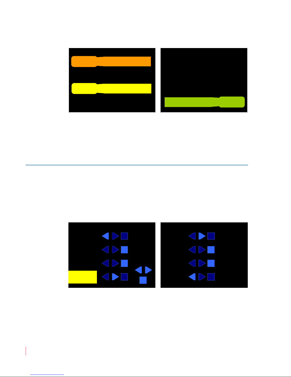
• Channel Icons: These indicators identify the channel number and
the status of the channel. Refer to Table 1–2 below for the channel
legend.
Table 1–2 Channel Icon Descriptions
Channel Unmuted Muted
Left
Right
Center
8
821091: AMP1-MADIe User Guide
© 2012 Wohler Technologies, Inc. All rights reserved.
• Level Meters: You can monitor and display meters for any eight
channels in the MADI input signal. To listen to some of the eight
channels, press the Channel Select button (to highlight in yellow)
the channel(s) you want to hear. Press the
to alternately mute or unmute the highlighted channel(s). The
channel(s) will be summed to the speakers as indicated by bright
Channel Volume knob

Chapter 1 Installation
Main Screen
blue channel icons. Rotate the Channel Volume knob to adjust the
level of the highlighted channel(s). The narrow bar under each level
meter shows the position of the Channel Volume knob for each
channel. The yellow Channel Volume knob always works for only
the yellow highlighted channels.
Adjust the Master Volume and Balance controls as necessary.
You can also give the channels unique names. Simply connect a PC
to the Ethernet port and run the AMP1-MADIe GUI setup program.
Refer to Appendix A on page 53 for details.
You can also give this AMP1-MADIe unit a unique name. Simply
connect a PC to the Ethernet port and run the AMP1-MADIe GUI
setup program. Refer to Appendix A on page 53 for details.
For more information on using the AMP1-MADIe, continue on to
Chapter 2: Operation on page 11.
821091: AMP1-MADIe User Guide
© 2012 Wohler Technologies, Inc. All rights reserved.
9


Introduction
Overview
This chapter describes how to operate the AMP1-MADIe’s Main
Screen
Topics
and how to transfer configuration files to/from a flash drive.
CHAPTER 2
Operation
Topics Page
Initial Operation 12
Monitor Channel Selection 12
Selecting Different Channels for Monitoring 13
Adjusting the Volume of Each Channel 15
Selecting the Multimode Optical Input 16
Using the Balanced Analog Outputs 17
Pre Fade or Post Fade Metering 18
Saving Your Settings 19
USB Port Functionality 20
821091: AMP1-MADIe User Guide
© 2012 Wohler Technologies, Inc. All rights reserved.
11

Chapter 2 Operation
PCR1-AD
Bob
31
64
-60-50 -40 -30 -20 -10 0
PCR1-GFX
Phil
PCR3-PGM
1
2
PCR2-DIR
Bucky
MUTED
5
23
11
17
REM-24
NVG/NYJ
ANNC-12
Costas
TAPE-SUP
Dave
REM-12
LONDON
Preset 1: Master Control
-60-50 -40 -30 -20 -10 0
MUTED
Unit Name
Post Fade
Metering
Initial Operation
Initial Operation
When you first power your AMP1-MADIe, it will be ready to monitor
the first eight MADI channels from the BNC input. Turning up the
Master Volume will let you hear all eight channels at once. By default,
the odd-numbered channels will sound in the left speaker, and the
even-numbered channels will sound in the right speaker, but you can
easily change this any way you like.
Chances are that you will want to change this operation to better suit
your needs. This chapter is devoted to explaining how to easily make
the changes you need so that the AMP1-MADIe operates just the way
you need it to.
Monitor Channel Selection
Any or all of the eight metered channels can be mixed to the speakers
and monitored. To change the channels you hear, press the Channel
Select
highlight them in bright yellow. After doing this, pressing the yellow
Channel Volume knob will mute or unmute these channels. The blue
channel icons in the middle of the screens are bright if the channel is
unmuted or dark if it is muted.
Figure 2–1 Main Screen with One Channel S elected
button(s) adjacent to the channels you want to change. This will
for Modification
12
821091: AMP1-MADIe User Guide
© 2012 Wohler Technologies, Inc. All rights reserved.
Chapter 2 Operation
Preset Selection
Preset 5
Default 5
Preset 6
Default 6
Preset 7
Default 7
Preset 1
Master Control
Preset 2
Truck 1
Preset 4
Default 4
Preset 3
Truck 2
Select a Preset
to save or
recall.
To exit without
changing
anything, pr ess
Preset Select
again.
Preset 8
Default 8
Selecting Different Channels for Monitoring
Selecting Different Channels for
Monitoring
Default Presets
By default, the eight presets in the AMP1-MADIe are set up to monitor
the 64 MADI channels as shown in Table 2–1 below.
Table 2–1 AMP1-MADIe Preset Defaults
Preset
1 2 3 4 5 6 7 8
Monitored Channels
112345678
2 9 10 11 12 13 14 15 16
3 1718192021222324
4 2526272829303132
5 3334353637383940
6 4142434445464748
7 4950515253545556
8 5758596061626364
So, to monitor channels 9 through 16 instead of 1 through 8, press the
Select Preset button. The Preset Selection Menu will appear as
shown in Figure 2–2 below.
Figure 2–2 Preset Selection Menu
Then press the button corresponding to Preset 2 on the screen and the
Preset Action Menu will appear as shown in Figure 2–3 on page 14.
© 2012 Wohler Technologies, Inc. All rights reserved.
821091: AMP1-MADIe User Guide
13
Chapter 2 Operation
Preset Action
Recall this Preset
Save the current config
to this Preset
Recall
Save
Exit with no changes at
all
Exit
Current Config: Default 1
Selected Preset: Default 8 (Preset 8)
Press Chan Assign to exit.
Channel Assignment Menu
11 1
3131 31
22 2
6464 64
Turn
Channel
Volume to
pick a
MADI
channel.
Press
Channel
Volume
to assign
Left,
Right,
or
Center.
55 5
2323 23
1111 11
1717 17
RL
PCR1-AD
Bob
PCR1-GFX
Phil
PCR3-PGM
PCR2-DIR
Bucky
REM-24
NVG/NYJ
ANNC-12
Costas
TAPE-SUP
Dave
REM-12
LONDON
C
Selecting Different Channels for Monitoring
Figure 2–3 Preset Action Menu
Press the
Recall button. Now the second eight channels, 9 through 16
will be monitored.
Press the Exit button to return to the Main Screen.
Selecting Any Eight Channels
Pressing the Channel Assignment button lets you quickly assign any
MADI channel to any metering channel position. Press the Channel
Assign
shown in Figure 2–4 below.
Figure 2–4 Channel Assignment Menu
ment button to display the Channel Assignment Menu as
Basic instructions are on the screen. Press the
corresponding to the metering channel position you want to reassign. It
14
821091: AMP1-MADIe User Guide
© 2012 Wohler Technologies, Inc. All rights reserved.
will highlight in yellow.
Channel Select button

Chapter 2 Operation
Adjusting the Volume of Each Channel
• Press the Channel Volume knob to select where you want to
monitor this channel: the Left, Right, or Center (both channels).
• Rotate the Channel Volume knob to select a MADI channel.
Note:
Repeat this with other channels as needed. Press the Channel
Assign
The channel names shown cannot be changed from this
menu. They can be changed from the Manager software.
Refer to Chapter 3.
ment button to exit this screen and return to the Main Screen.
Adjusting the Volume of Each Channel
You can adjust the volume of each channel individually. Press the
Channel Select button(s) adjacent to the channel(s) you want to
change to highlight them in yellow. Then turn the yellow Channel
Volume
lengthen or shorten according to the Channel Volume knob position,
indicating how much you are changing the volume.
knob. The green line under the meters for these channels will
Adjusting the Speaker Audio Tone
Controls
Depending on the listening environment, you may need to adjust the
tone of the audio to improve the sound coming from the speakers. You
can do this with the digital
Audio Menu 2.
1. To adjust these controls, hold the Channel Volume knob for at
least three seconds until Audio Menu 1 displays.
2. Press the Next button to proceed to Audio Menu 2.
© 2012 Wohler Technologies, Inc. All rights reserved.
Bass and Treble tone controls provided in
821091: AMP1-MADIe User Guide
15

Chapter 2 Operation
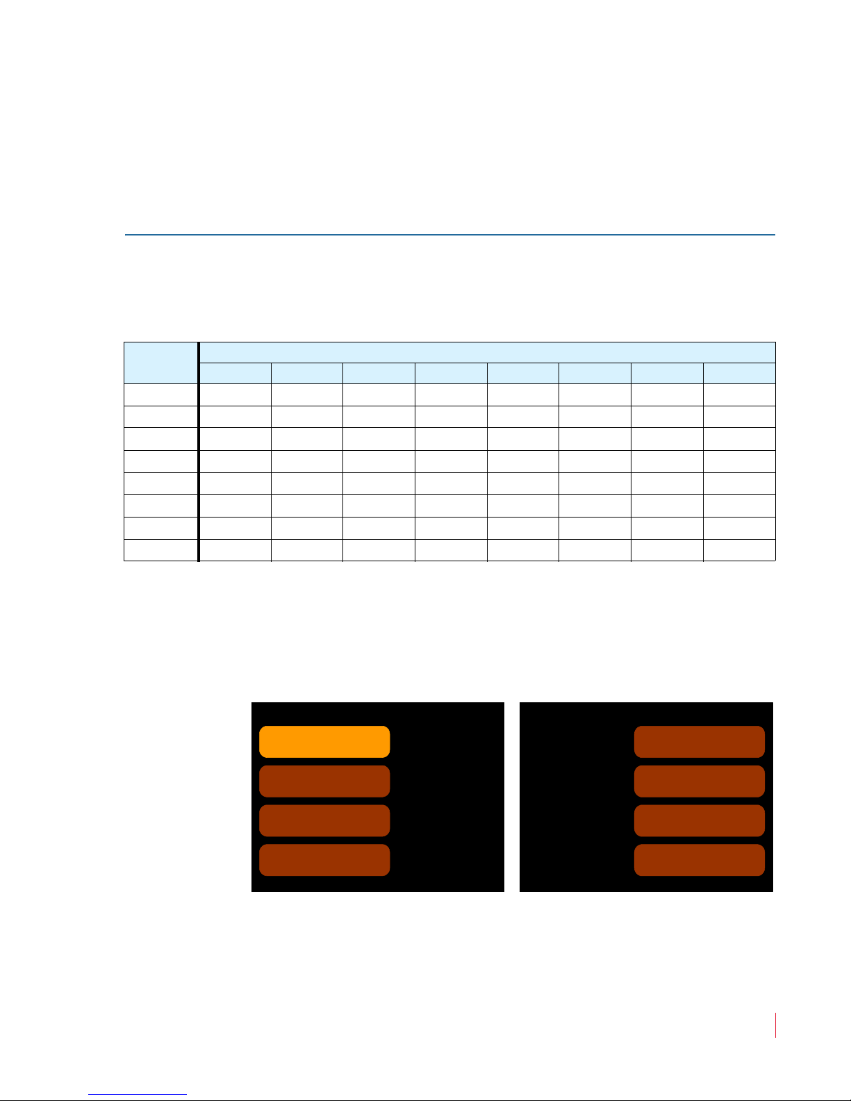
Audio Menu 2
Flat response, tone controls
set to 0 dB
Flat
NextBack
Tone Controls
To quickly exit Menus, press Channel Volume for 3 seconds
0 dB
0 dB
Bass
Treble
The Tone
Controls
affect the
speaker
sound only.
4 ms Audio Delay
Selecting the Multimode Optical Input
Figure 2–5 Audio Menu 2
Pressing the
Flat button brightens the Flat setting and darkens the
Bass and Treble settings to brown, and produces a flat response. This
is the default setting. However, the Bass and Treble settings are
retained so you can recall them the next time you press either the Bass
or Treble button.
Press either Treble or Bass and then rotate the Channel Volume to
increase or decrease the response of each. The range is
± 12 dB in 2 dB steps.
Press the Channel Volume knob for at least three seconds to return to
the Main Screen.
Note:
The tone controls only apply to the internal speakers, not to
the analog outputs or headphone output.
Selecting the Multimode Optical Input
The AMP1-MADIe can monitor either the BNC or the multimode
optical fiber inputs on the rear panel.
1. To switch between the two, hold the Channel Volume knob for
at least three seconds until the
2. Press the Next button twice to proceed to the Options Menu.
16
821091: AMP1-MADIe User Guide
© 2012 Wohler Technologies, Inc. All rights reserved.
Audio Menu 1 displays.
 Loading...