

Wohler AMP1-16V-MD, AMP1-E16V-MD User Manual

AMP1-16V Series
USO RESTRITO
• AMP1-16V-MD • AMP1-E16V-MD
1RU, 3Gb/s, 16-Channel, Audio and
Video Monitor
User Guide
(Software Version: 3.2x)
Part Number 821697, Revision P

USO RESTRITO
© 2013 Wohler Technologies, Inc. and PANORAMA. All rights reserved.
This publication is protected by federal copyright law. No part of this publication may be
copied or distributed, stored in a retrieval system, or translated into any human or computer
language in any form or by any means electronic, mechanical, manual, magnetic, or otherwise,
or disclosed to third parties without the express written permission of Wohler Technologies.
Reproduction
Licensed users and authorized distributors of Wohler Technologies, Inc. products may copy
this document for use with Wohler Technologies., Inc. products provided that the copyright
notice above is included in all reproductions.
Customer Support
Wohler Technologies, Inc.
31055 Huntwood Avenue
Hayward, CA 94544
www.wohler.com
Phone: 510-870-0810
FAX: 510-870-0811
US Toll Free: 1-888-596-4537
(1-888-5-WOHLER)
Web: www.wohler.com
Sales: sales@wohler.com
Support: support@wohler.com
Disclaimers
Even though Wohler Technologies, Inc. has tested its equipment and software, and reviewed
the documentation, Wohler Technologies, Inc makes no warranty or representation, either
express or implied, with respect to software, documentation, their quality, performance,
merchantability, or fitness for a particular purpose.
In no event will Wohler Technologies, Inc. be liable for direct, indirect, special, incidental, or
consequential damages resulting from any defect in the hardware, software, or its
documentation, even if advised of the possibility of such damages.
Some states do not allow the exclusion or limitation for incidental or consequential damages, so
the above exclusion or limitation may not apply to you
Printing
This document is intended to be printed on a duplex printer, such that the copy appears on
both sides of each page. This ensures that all new chapters start on a right-facing page.
This document looks best when printed on a color printer since some images may be indistinct
when printed on a black and white printer.
PDF
All text strings appearing in this shade of blue are hyperlinks.
Other Technologies and Products
Dolby is a registered trademark of Dolby Laboratories, Inc.
Microsoft Windows, and Internet Explorer are registered trademarks of Microsoft Corporation.
.
Last Update
September 22, 2014
82 1 6 97 : AM P 1 -16 V S e r ie s U se r Gu i d e
ii
© 2 0 13 W o h le r Tec h n ol o g i es , In c . A l l ri g h ts r e s e r ved .

Table of Contents
USO RESTRITO
Chapter 1. Quick Start. . . . . . . . . . . . . . . . . . . . . . . . . . . . . 1
Introduction ...................................................................1
Overview..................................................................1
Topics ......................................................................1
Safety Instructions ..........................................................2
Installation Recommendations...........................................3
Mounting..................................................................3
Heat Dissipation ........................................................3
Power ......................................................................3
Compliance ....................................................................4
FCC .........................................................................4
IC-ECES-003 ............................................................4
Using the Monitor ............................................................4
Front Panel ...............................................................5
Back Panel................................................................6
Getting Started ...............................................................7
Configuring the System....................................................9
Chapter 2. The “How Do I...” Chapter . . . . . . . . . . . . . . . . 11
Introduction .................................................................11
Overview................................................................ 11
Topics .................................................................... 11
Notation....................................................................... 12
Frequently Asked Questions............................................ 13
How do I Select the Inputs I Want to Hear in the
Speakers? .............................................................. 13
How do I Decode and Monitor a Dolby Bitstream? ........14
How do I Decode and Monitor a Dolby Bitstream
(Continued)?........................................................... 15
© 2 0 1 3 W o h le r Te c h n o lo g i es , I n c . A l l ri g h ts r e s e r ved .
82 1 6 97 : AM P 1 -16 V S e r ie s U se r Gu i d e
iii

USO RESTRITO
How do I Cluster Meter Pairs Together for Easy
Readability? ............................................................16
How do I Customize the Meter Scales?........................17
How do I Configure a Hot Key to Solo a Cluster? ..........18
How do I Configure a Hot Key to Mute a Cluster? .........19
How do I Configure the AES and Analog Outputs? ..........21
How do I Set Up for External Surround Sound?..............23
How Do I Sync Internal Speaker Audio with an External
Video Monitor? ........................................................24
How Do I Use Presets to Change Inputs? ....................25
How Do I Quickly Recall Presets from the Main Screen?.26
How do I Display the Loudness of a Cluster of Channels? .
27
How do I Display Dolby Metadata instead of Video?........29
How do I Display Dolby Metadata Along With Video?.....30
How do I Adjust the Screen Saver or Screen Brightness? .
31
How Do I Terminate or Unterminate AES Inputs? .........32
How do I Find Software Version Information? ..............33
Chapter 3. Audio and Metering. . . . . . . . . . . . . . . . . . . . . 35
Introduction..................................................................35
Overview ................................................................35
Topics ....................................................................35
Configuration Options ....................................................36
Configuring the Audio Outputs.........................................36
Overview ................................................................36
Surround Sound ......................................................37
Stereo Downmix ......................................................38
AES and Analog Outputs ...........................................41
Level Metering ..............................................................44
Overview ................................................................44
Metering Menus .......................................................45
82 1 6 97 : AM P 1 -16 V S e r ie s U se r Gu i d e
iv
© 2 0 13 W o h le r Tec h n ol o g i es , In c . A l l ri g h ts r e s e r ved .

Chapter 4. Video and Data . . . . . . . . . . . . . . . . . . . . . . . . 47
USO RESTRITO
Introduction .................................................................47
Overview................................................................ 47
Topics .................................................................... 47
Configuration Options .................................................... 48
Overview................................................................ 48
Video Menus ........................................................... 49
Chapter 5. Efficiency Enhancements . . . . . . . . . . . . . . . . . 51
Introduction .................................................................51
Overview................................................................ 51
Topics .................................................................... 51
Presets ........................................................................ 52
Overview................................................................ 52
Saving Presets ..................................................52
Recalling Presets ............................................... 52
Naming or Renaming ...............................................53
Clearing a Preset ..................................................... 54
Recalling a Preset On Power Up .................................55
Hot Keys ...................................................................... 55
Overview................................................................ 55
Mutes and Solos ......................................................55
Defining/Modifying a Hot Key ....................................56
Creating a Preset Hot Key......................................... 57
Naming/Renaming a Hot Key ....................................57
Copying Presets to Another Monitor .................................58
Preset Files............................................................. 58
Verifying Compatibility .............................................59
Backing Up the Saved Presets ...................................61
Copying the Presets to Another Monitor ...................... 61
General Purpose Inputs and Outputs (GPI/Os)................... 62
© 2 0 1 3 W o h le r Te c h n o lo g i es , I n c . A l l ri g h ts r e s e r ved .
82 1 6 97 : AM P 1 -16 V S e r ie s U se r Gu i d e
v

USO RESTRITO
Turning Active Help On or Off ..........................................63
Chapter 6. Menu List. . . . . . . . . . . . . . . . . . . . . . . . . . . . . 65
Introduction..................................................................65
Overview ................................................................65
Topics ....................................................................65
Menu Navigation Overview..............................................66
AES Output Configuration Menu.......................................68
Analog Output Configuration Menu...................................70
Configuration Selection Menu ..........................................72
Cluster Configuration Menu .............................................73
Dolby Setup Menu .........................................................74
Hardware Configuration Menu .........................................75
Label Menu Screen ........................................................77
Loudness Configuration Menu Screen ...............................78
Main Screen..................................................................79
Main Screen Hot Key Button Configuration Menu................81
Meter Configuration Menu...............................................82
Monitor Mixer Configuration Menu....................................84
Option Configuration Menu..............................................86
Preset Management Menu...............................................87
Screen Display Menu......................................................88
Screen Information Setup Menu ......................................89
Unit Information Menu ...................................................91
Chapter 7. Firmware Updates. . . . . . . . . . . . . . . . . . . . . . 93
Introduction..................................................................93
Overview ................................................................93
Topics ....................................................................93
Upgrade Requirements ...................................................94
Comparing Firmware Versions .........................................94
Upgrading the Netburner Software...................................96
82 1 6 97 : AM P 1 -16 V S e r ie s U se r Gu i d e
vi
© 2 0 13 W o h le r Tec h n ol o g i es , In c . A l l ri g h ts r e s e r ved .

Upgrading the Sub-Processor Firmware ............................ 98
USO RESTRITO
Chapter 8. Features and Specifications. . . . . . . . . . . . . . 105
Introduction ............................................................... 105
Overview.............................................................. 105
Topics .................................................................. 105
Features .................................................................... 106
Product Benefits .................................................... 106
Distinction Between Models..................................... 107
Additional Features ................................................ 107
Compliance........................................................... 108
Standards ............................................................ 108
Specifications ............................................................. 108
Technical Functional Overview....................................... 110
Appendix 9. Establishing Connectivity . . . . . . . . . . . . . . 113
Introduction ............................................................... 113
Overview.............................................................. 113
Topics .................................................................. 113
Connectivity Options.................................................... 114
Connecting to a LAN .................................................... 114
Launching the Setup Tool........................................ 114
Setting a Static Ethernet Configuration ..................... 115
Connecting Directly ..................................................... 117
Using AutoIP......................................................... 117
Setting a Static IP in the AMP1-16V ............................... 120
Setting a Static IP in a Windows XP Computer ................. 121
Setting a Static IP in a Windows 7 Computer................... 126
Appendix 10. Setting Up File Transfers. . . . . . . . . . . . . . 131
Introduction ............................................................... 131
© 2 0 1 3 W o h le r Te c h n o lo g i es , I n c . A l l ri g h ts r e s e r ved .
82 1 6 97 : AM P 1 -16 V S e r ie s U se r Gu i d e
vii

USO RESTRITO
Overview .............................................................. 131
Topics .................................................................. 131
Navigating to the Unit Information Menu ........................ 132
Enabling FTP Access..................................................... 133
82 1 6 97 : AM P 1 -16 V S e r ie s U se r Gu i d e
viii
© 2 0 13 W o h le r Tec h n ol o g i es , In c . A l l ri g h ts r e s e r ved .

Introduction
USO RESTRITO
Overview
The AMP1-16V-MD and AMP1-E16V-MD are Wohler’s first 1RU,
16-channel, 3G audio/video monitors. These units come with three 2.4”
video screens and an easy-to-use configuration interface that provides
flexible audio metering, video monitoring, and other data display.
CHAPTER 1
Quick Start
Topics
Topics Page
Quick Start 1
Safety Instructions 2
Installation Recommendations 3
Compliance 4
Using the Monitor 4
Getting Started 7
Configuring the System 9
© 2 0 1 3 W o h le r Te ch n o lo g i es , I n c . Al l rig h t s r e s e r v ed.
82 1 6 97 : AMP 1 - 16 V S e r i e s U se r Gu i d e
1

Ch ap te r 1 Q u ic k St ar t
USO RESTRITO
Sa f e t y I ns t r u c ti o n s
Safety Instructions
1. Read, keep, and follow all of these instructions; heed all warnings.
2. Do not use this equipment near water.
3. Use only a dry cloth to clean the equipment.
IMPORTANT:
4. Do not block any ventilation openings. Install only
with the instructions in the section entitled, “Installation
Recommendations” on page 3.
5. Do not install near any heat source such as a radiator, heat register,
amplifier, or stove.
6. Do not expose the equipment to rain or moisture.
7. Do not attempt to plug the unit into a two-blade outlet (with only
two prongs of equal width).
By design, this monitor will only plug into a three-prong outlet for
your safety. If the plug does not fit into your outlet, contact an
electrician to replace the obsolete outlet.
8. Protect the power cord from being walked on or pinched,
particularly at plug’s source on the equipment and at the socket.
9. Use only the attachments/accessories specified by th
manufacturer.
in accordance
e
10. Unplug the equipment during lightning storms or when unused
for long periods of time.
11. Refer all servicing to qualified service personnel. Servicing will be
required under all of the following conditions:
• The equipment has been damaged in any way, such as when
the power-supply cord or plug is damaged.
• Liquid had been spilled or objects have fallen onto the
equipment.
• The equipment has been exposed to rain or moisture.
• The equipment does not operate normally.
• The equipment has been dropped.
82 1 6 97 : AM P 1 -16 V S e r ie s U se r Gu i d e
2
© 2 0 13 W o h le r Tec h n ol o g i es , In c . A l l ri g h ts r e s e r ved .

Ch ap te r 1 Quick Start
USO RESTRITO
In s t a l la ti on R ec om me nd at io ns
Installation Recommendations
Mounting
The unit is designed to install into a standard 19" rack, mounted at eye
level for best visual observation of the monitor screens. After installing
the AMP1-16V-MD, remove the clear, plastic protective covers from
each screen using the tabs provided.
Heat Dissipation
The ambient temperature inside the mounting enclosure should not
exceed 40° Celsius (104° Fahrenheit). Adjacent devices can be rack
mounted (or stacked) in proximity to the unit if the above temperature
is not exceeded. If the product must be operated in an environment
with an elevated temperature, allow a 1RU (1.75”/44.45mm) space
above and below the unit for air circulation.
Important:
Power
To reduce noise, neither the AMP1-16V-MD nor the AMP1-E16V-MD
have any fans. As a result, the heat generated by the class D power
amplifiers, power supplies, and other components is vented by slots in
the sides of the unit. Therefore, as a safety precaution, we advise you to
be sure to allow proper ventilation on both sides of the unit.
The AMP1-16V-MD has a standard IEC connector on the rear panel
from which it can connect to AC mains power (100 to 240 VAC ± 10%,
50/60 Hz, 65W). You may use the power cord provided, or another
approved cord, to adapt the unit to the proper country-specific power
connection.
© 2 0 1 3 W o h le r Te c h n o lo g i es , I n c . A l l ri g h ts r e s e r ved .
82 1 6 97 : AM P 1 -16 V S e r ie s U se r Gu i d e
3

Ch ap te r 1 Q u ic k St ar t
USO RESTRITO
Co mp li an ce
Compliance
FCC
This equipment has been tested and found to comply with the limits for
a Class A digital device, pursuant to part 15 of the FCC Rules. These
limits are designed to provide reasonable protection against harmful
interference when the equipment is operated in a commercial
environment. This equipment generates, uses, and can radiate radio
frequency energy and, if not installed and used in accordance with the
instruction manual, may cause harmful interference to radio
communications. Operation of this equipment in a residential area is
likely to cause harmful interference in which case the user will be
required to correct the interference at his own expense.
IC-ECES-003
This Class A digital apparatus complies with Canadian ICES-003.
Cet appareil numérique de la classe A est conforme à la norme
NMB-003 du Canada.
Using the Monitor
This section provides a brief overview of the controls on the front
panel, and the connectors on the back panel of the monitor.
82 1 6 97 : AM P 1 -16 V S e r ie s U se r Gu i d e
4
© 2 0 13 W o h le r Tec h n ol o g i es , In c . A l l ri g h ts r e s e r ved .
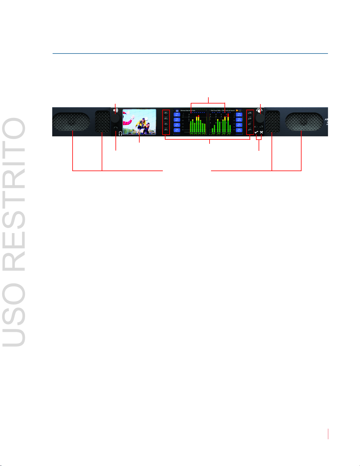
Front Panel
Speakers
Headphone Jack
Volume
(Rotary Knob)
Balance and Menu
Navigation
(Rotary Knob)
Video Monitor
Hot Keys/Menu Buttons
Data/Menu
Monitors
Menu Navigation Buttons
USO RESTRITO
Figure 1–1 Front Panel Layout
Ch ap te r 1 Quick Start
Us in g th e Mo ni to r
Speakers: A
amplifiers driving two (left/right) wide range speakers.
Headphone Jack: A class B amplifier drives the front panel 3.5 mm
jack for an optional headphone.
Balance and Volume Rotary Knobs: Control knobs are on the left and
right of the front panel video displays. The left knob controls the
Volume and the speaker output and can be programmed to control the
AES and Analog outputs. Pressing this control drops the internal
speaker volume by 20 dB. Pressing it a second time mutes the internal
speakers entirely. Pressing it a third time brings the internal speaker
volume back to normal. Turning the knob to increase the volume
increases it from the current volume, whether from the 20dB dip or
from the completely muted state.
The right knob adjusts the Balance between the speakers. Pressing the
knob returns the audio balance to center. This knob is also used for
setting adjustments when programming the options and features in the
configuration menus.
udio monitoring is achieved through the use of class D
Video Screen: This monitor (left) displays either video and/or data
such as help for the Menu and Data Screens.
Menu and Data Screens: These two screens on the right work together
to display bar graphs and the configuration menus.
© 2 0 1 3 W o h le r Te c h n o lo g i es , I n c . A l l ri g h ts r e s e r ved .
82 1 6 97 : AM P 1 -16 V S e r ie s U se r Gu i d e
5
Ch ap te r 1 Q u ic k St ar t
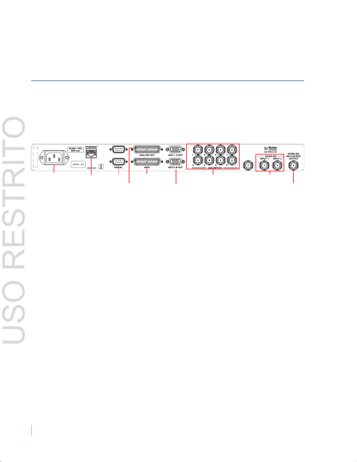
Power Ethernet Serial GPI/O
AES Outputs
(1 - 4 and 5 - 8)
AES Inputs HD/SD-SDI Inputs
3G/HD/SD-SDI
Re-Clocked Output
Analog Output
USO RESTRITO
Us in g th e Mo ni to r
Hot Keys/Push Buttons: Ten buttons are used for menu navigation
and hot key access to solo, mute, and preset functions.
Back Panel
The AMP1-16V-MD and AMP1-E16V-MD back panel contains all of the
connectors except for the headphone jack as shown in Figure 1–2
below.
Figure 1–2 Back Panel Layout
• Power: The AMP1-16V-MD and AMP1-E16V-MD use a standard
IEC power cord for the 100 to 240 VAC power connection.
• Ethernet: The Ethernet port is used for system software upgrades.
• Serial:
• Analog Outputs: This DB-25F connector provides eight channels of
balanced analog outputs.The source of these signals is controlled by
the setup menus. (The pin out of this connector is shown in Table 3–
3 on page 43.)
• AES Outputs: Each of these two HD-15F connectors supplies four
pairs of unbalanced AES outputs for a total of eight. The source of
these signals is determined by the setup menus. (The pin out of
these connectors is shown in Table 3–2 on page 42.)
• AES Inputs: Each of these eight BNC connectors provides an
unbalanced AES input. The monitoring of these signals is
determined by the setup menus.
This DB-9F connector is used for system software upgrades.
• 3G/HD/SD-SDI Inputs: These two BNC connectors input two
separate SDI signals. Front panel controls select between the two for
monitoring or down converting.
82 1 6 97 : AM P 1 -16 V S e r ie s U se r Gu i d e
6
© 2 0 13 W o h le r Tec h n ol o g i es , In c . A l l ri g h ts r e s e r ved .
• 3G/HD/SD-SDI Re-Clocked Output: This BNC connector outputs
Solo
Pair 5
Solo
Pair 6
Solo
Pair 7
0
-60
-10
-20
-30
-40
-50
P
a
i
r
5
P
a
i
r
6
P
a
i
r
7
P
a
i
r
8
Solo
Pair 8
-22
Solo
Pair 3
Solo
Pair 1
0
-60
-50
-40
-30
-10
-20
P
a
i
r
1
P
a
i
r
2
P
a
i
r
3
P
a
i
r
4
Solo
Pair 4
Solo
Pair 2
USO RESTRITO
a re-clocked replica of the selected 3G/HD/SD-SDI input signal.
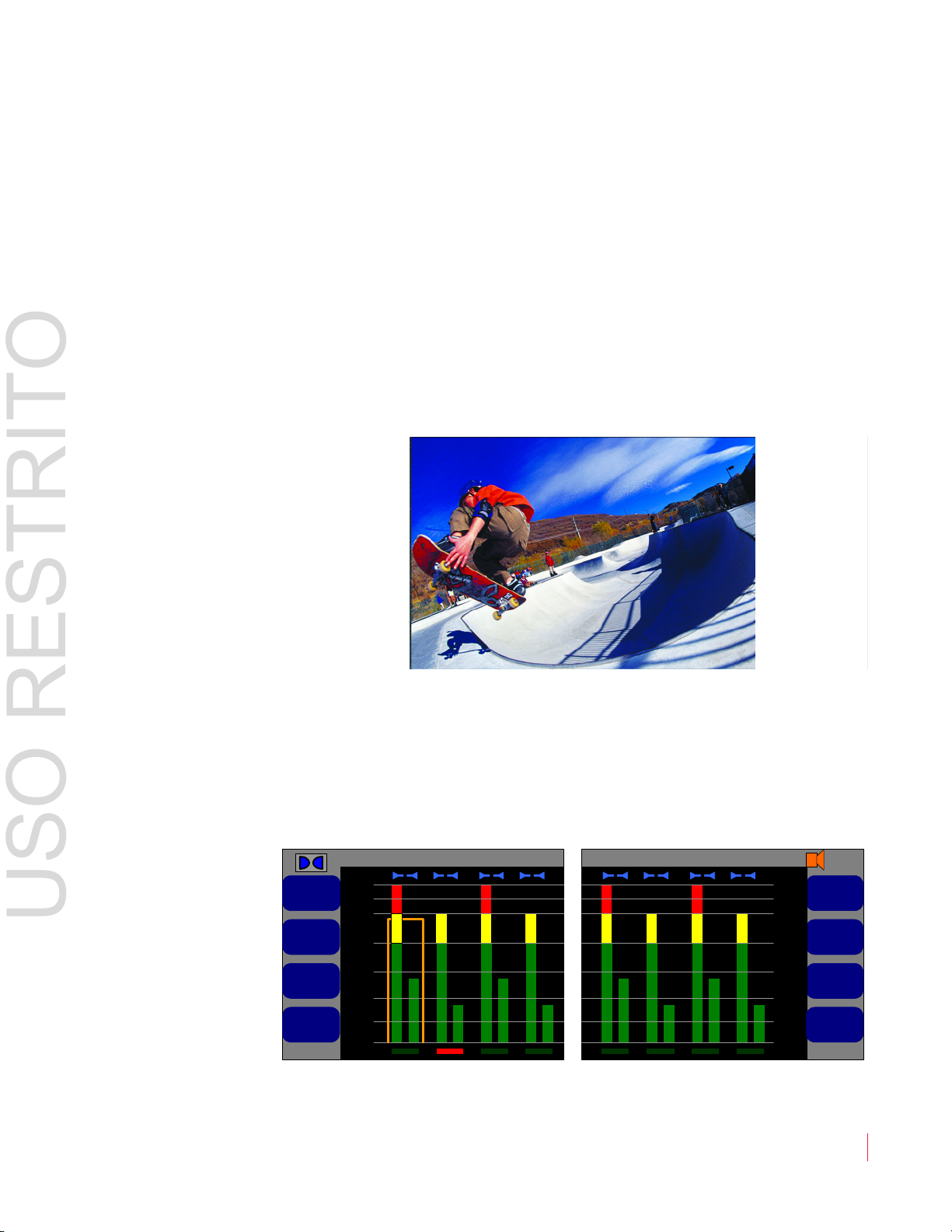
Getting Started
Once you have connected a 3G/HD/SD SDI video signal to one of the
video inputs on the back of the unit, it should display on the video
monitor after a few seconds.
Figure 1–3 Video Monitor Display (Left)
Ch ap te r 1 Quick Start
Ge t t in g St ar te d
To begin any procedure on the AMP1-16V-MD or the AMP
1-E16V-MD,
powering up the system should display the video input on the left
screen, and the audio level meters on the Main Screen as shown in
Figure 1–4 below.
Figure 1–4 Main Screen (Center and Right)
© 2 0 1 3 W o h le r Te c h n o lo g i es , I n c . A l l ri g h ts r e s e r ved .
82 1 6 97 : AM P 1 -16 V S e r ie s U se r Gu i d e
7
Ch ap te r 1 Q u ic k St ar t
Configuration Selection Menu
Monitor Menu
Preset ManagementRecall a Preset
8
SDI Source
Screen Display
Menu
2
Analog Output
Menu
AES Output Menu
Late Show
Dolby Menu
Push to recall
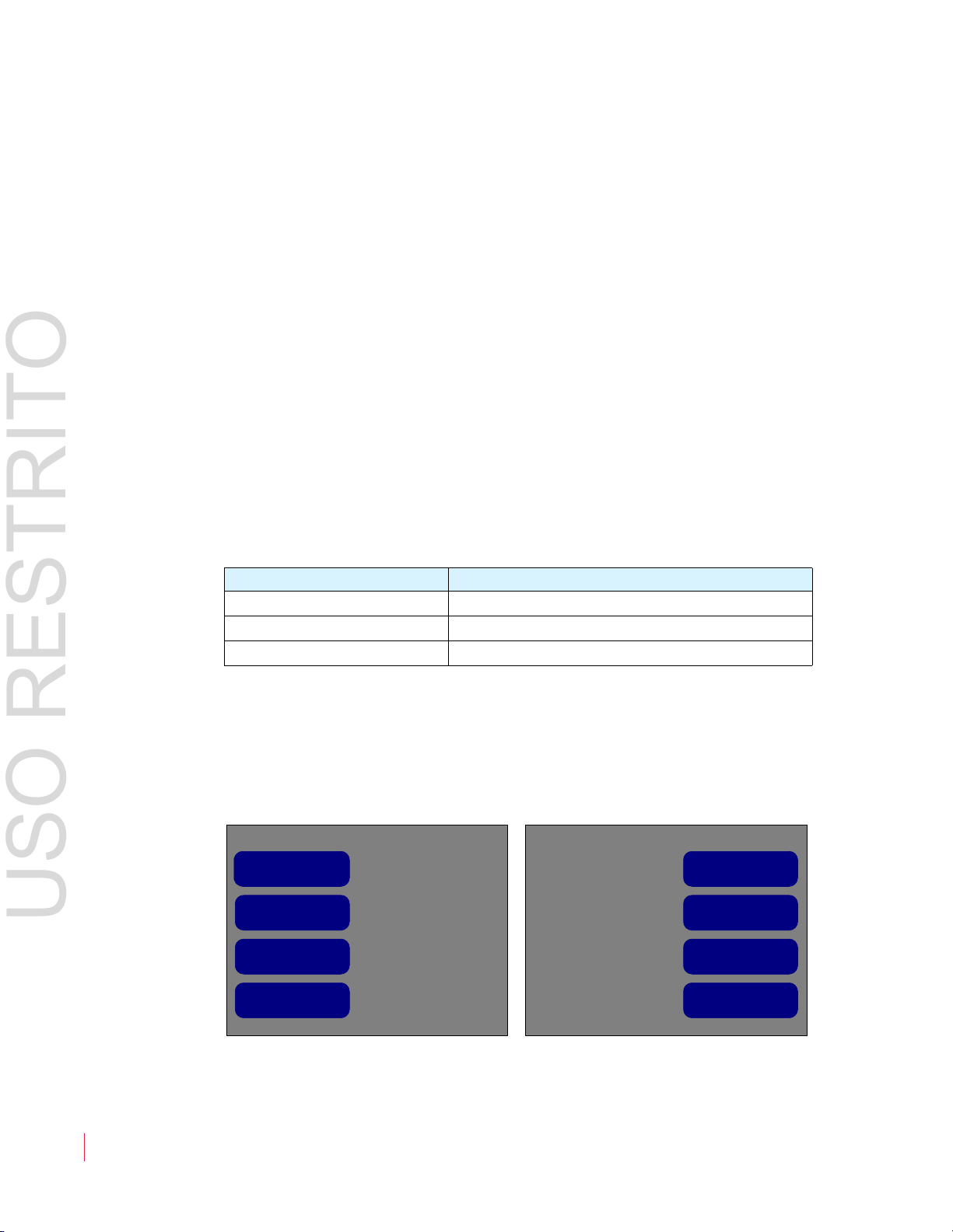
USO RESTRITO
Ge t t in g St ar te d
You can launch the menu system by pressing either of the buttons
directly below the Balance control. These same buttons also either
(Save and Exit) or (Cancel and Exit). Context-sensitive, active
help appears automatically on the left hand screen for any function.
From the Main Screen, press either the button or the button to
display the Configuration Selection Menu. The eight buttons
surrounding the screen allow you to access options or functions on the
screen or to proceed to other menus.
Note that the
Screen is displayed, it controls the audio balance, but when any setup
Balance knob is multifunctional. When the Main
menu is displayed, it is used to adjust settings. The actual audio balance
does not change while the Balance knob is being used for setting up
the product.
Generally, to make changes, press the button next to the item you want
to change. Then rotate the Balance knob to highlight the option that
you want and press the Balance knob to select it.
Table 1–1 Typical Knob/Button Functionality
Action Result
Press an option button Highlights the name of the option
Rotate the Balance knob Scrolls through the available options
Press the
Balance knob Selects the highlighted option
To move back up in the menu tree, press either the button (to save)
or the button (to cancel) repeatedly until you reach the
Screen.
Main
Figure 1–5 Configuration Selection Menu
82 1 6 97 : AM P 1 -16 V S e r ie s U se r Gu i d e
8
© 2 0 13 W o h le r Tec h n ol o g i es , In c . A l l ri g h ts r e s e r ved .

Configuring the System
USO RESTRITO
The functional descriptions fall under the following categories:
• Configuring Audio and Metering (Chapter 3 on page 35)
• Configuring Video and Data (Chapter 4 on page 47)
• Configuring Presets and Hot Keys (Chapter 5 on page 51)
Ch ap te r 1 Quick Start
Co nf ig u r in g t h e Sy st em
© 2 0 1 3 W o h le r Te c h n o lo g i es , I n c . A l l ri g h ts r e s e r ved .
82 1 6 97 : AM P 1 -16 V S e r ie s U se r Gu i d e
9

Ch ap te r 1 Q u ic k St ar t
USO RESTRITO
Co nf ig u r in g th e Sy st em
82 1 6 97 : AM P 1 -16 V S e r ie s U se r Gu i d e
10
© 2 0 13 W o h le r Tec h n ol o g i es , In c . A l l ri g h ts r e s e r ved .

CHAPTER 2
USO RESTRITO
The “How Do I...” Chapter
Introduction
Overview
This chapter answers many questions that naturally come up as the
AMP1-16V Series monitor is first put into service.
Topics
Topics Page
Introduction 11
How do I Select the Inputs I Want to Hear in the Speakers? 13
How do I Decode and Monitor a Dolby Bitstream? 14
How do I Decode and Monitor a Dolby Bitstream
(Continued)?
How do I Cluster Meter Pairs Together for Easy Readability? 16
How do I Customize the Meter Scales? 17
How do I Configure a Hot Key to Solo a Cluster? 18
How do I Configure a Hot Key to Mute a Cluster? 19
How do I Configure the AES and Analog Outputs? 21
How do I Set Up for External Surround Sound? 23
How Do I Sync Internal Speaker Audio with an External
Video Monitor?
How Do I Use Presets to Change Inputs? 25
How do I Display the Loudness of a Cluster of Channels? 27
15
24
How do I Display Dolby Metadata instead of Video? 29
How do I Display Dolby Metadata Along With Video? 30
© 2 0 1 3 W o h le r Te ch n o lo g i es , I n c . Al l rig h t s r e s e r v ed.
82 1 6 97 : AMP 1 - 16 V S e r i e s U se r Gu i d e
11
Ch ap te r 2 T h e “H ow D o I . . . ” C h ap te r
Configuration Selection
Menu
Main Screen
Monitor Menu
Monitor Mixer
Configuration Menu
Solo
Pair 5
Solo
Pair 6
Solo
Pair 7
0
-60
-10
-20
-30
-40
-50
P
a
i
r
5
P
a
i
r
6
P
a
i
r
7
P
a
i
r
8
Solo
Pair 8
-22
Solo
Pair 3
Solo
Pair 1
0
-60
-50
-40
-30
-10
-20
P
a
i
r
1
P
a
i
r
2
P
a
i
r
3
P
a
i
r
4
Solo
Pair 4
Solo
Pair 2
Configuration Selection Menu
Monitor Menu
Preset ManagementRecall a Preset
8
SDI Source
Screen Display
Menu
2
Analog Output
Menu
AES Output Menu
Late Show
Dolby Menu
Push to recall
Monitor Mixer Configuration Menu
160 mS
Audio Delay
Monitor Pair 1
Pair 1
Dolby Decoder Pair 1
+0 +0
Monitor Pair 2
Pair 2
SDI In Pair 2
+0+0
RL RL RL RL
Speaker Assign
Monitor Channel
Trim
Select Monitor Pair
Select Source Pair
Phase LED On/OffMute Speakers
w/ Headphone Always
Menu
Configuration Selection
Menu
Main Screen
Monitor Menu
Monitor Mixer
Configuration Menu
Menu
Or simply
USO RESTRITO
No ta t i on
Topics Page
How Do I Terminate or Unterminate AES Inputs? 32
How do I Find Software Version Information? 33
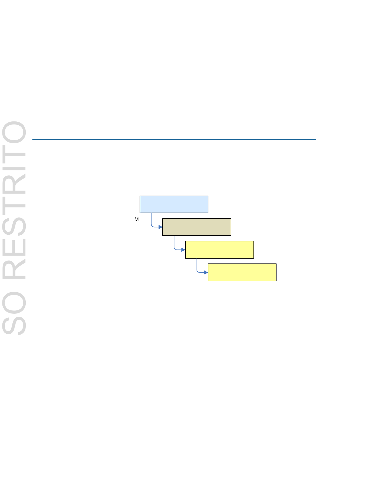
Notation
In this chapter, we use a shorthand method to show you how to
progress form the Main Screen to the menus. Refer to Figure 2–1 below.
Figure 2–1 Screen Notation
12
82 1 6 97 : AM P 1 -16 V S e r ie s U se r Gu i d e
© 2 0 13 W o h le r Tec h n ol o g i es , In c . A l l ri g h ts r e s e r ved .
Ch ap te r 2 The “How Do I...” Chapter
Configuration Selection
Menu
Main Screen
Monitor Menu
Monitor Mixer
Configuration Menu
Menu
Monitor Mixer Configuration Menu
160 mS
Audio Delay
Monitor Pair 1
Pair 1
AES In Pair 1
+0 +0
Monitor Pair 2
Pair 2
SDI In Pair 2
+0+0
RL RL RL RL
Speaker Assign
Monitor Channel
Trim
Select Monitor Pair
Select Source Pair
Phase LED On/OffMute Speakers
w/ Headphone Always
USO RESTRITO
Fr eq u e nt ly A sk ed Q ue st io ns
Frequently Asked Questions
For all of the following instructions, Active Help displays on the left
screen.
How do I Select the Inputs I Want to Hear in the Speakers?
The AMP1-16V-MD offers a wide variety of inputs. You many monitor
any 16 of the input channels, in any mix, on the meters and through the
speakers. Assigning inputs to be monitored is done in the Monitor
Mixer Configuration Menu:
1. Press the Select Monitor Pair control and then turn the Balance
knob to select the channel pair on which you want the input to be
monitored. Note that the channel pairs scroll right and left as you
turn the
channel pairs.
2. Press the Select Source Pair control and then turn the Balance
knob to select the input. Refer to the AES In Pair 1 in Figure 2–2
below.
Figure 2–2 Monitor Mixer Configuration Menu
3. Repeat Steps 1 and 2 for each input to be monitored.
Balance knob so that you can select any one of the eight
© 2 0 1 3 W o h le r Te c h n o lo g i es , I n c . A l l ri g h ts r e s e r ved .
82 1 6 97 : AM P 1 -16 V S e r ie s U se r Gu i d e
13
Ch ap te r 2 T h e “H ow D o I . . . ” C h ap te r
Configuration Selection
Menu
Main Screen
Menu
Dolby
Dolby
Setup Menu
Dolby Setup Menu
SDI In Channels 7/8
Decoder
Source
Program 1
Dolby E
Program
Channel 1
Pro-16
Mode Ch
Bitstream
Detect
Automatic
Dolby E or Mute
Dolby Digital or Mute
USO RESTRITO
Fr eq u e n t l y A sk e d Q ue st io ns
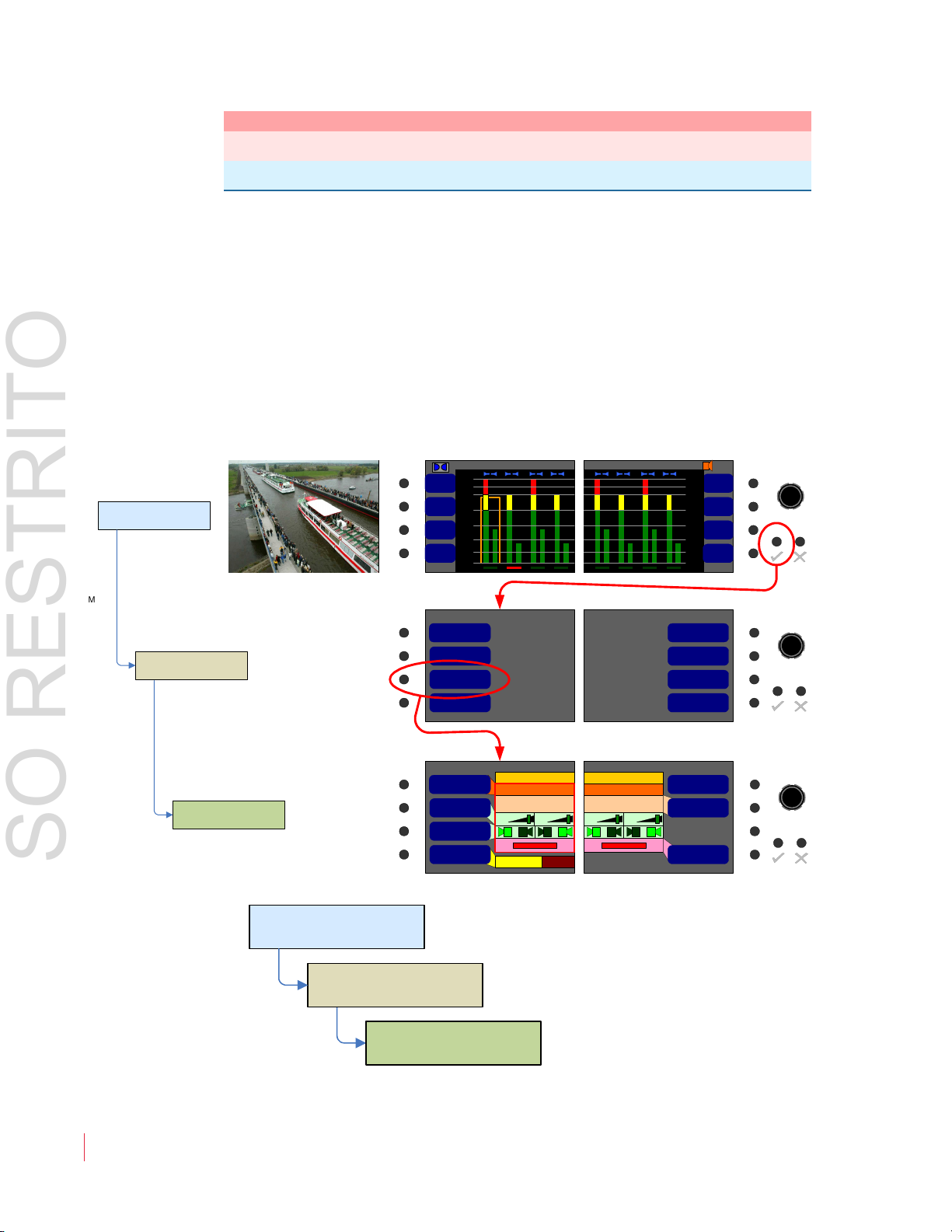
How do I Decode and Monitor a Dolby Bitstream?
You can continuously monitor a single Dolby bitstream from the SDI or
AES inputs even if the bitstream itself doesn't appear on the Main
Screen meters. You can also continuously monitor the Dolby
metadata.
Note:
The AMP1-E16V-MD must contain the optional Dolby
decoder card in order to decode a Dolby bitstream.
Setting up continuous Dolby bitstream monitoring is a two-step
process, first set up the Decoder card and then set up the monitoring
channels. The first step involves configuring the Dolby decoder card:
1. Press the
Balance knob to the AES or SDI channel pair that contains the
Decoder Source control button and then turn the
Dolby bitstream to be decoded.
Figure 2–3 Dolby Setup Menu
14
2. Follow the instructions on the next page to select the meter
channels on which you would like to view the decoded channels.
82 1 6 97 : AM P 1 -16 V S e r ie s U se r Gu i d e
© 2 0 13 W o h le r Tec h n ol o g i es , In c . A l l ri g h ts r e s e r ved .
Ch ap te r 2 The “How Do I...” Chapter
Configuration Selection
Menu
Main Screen
Monitor Menu
Monitor Mixer
Configuration Menu
Menu
Monitor Mixer Configuration Menu
160 mS
Audio Delay
Monitor Pair 1
Pair 1
Dolby Decoder Pair 1
+0 +0
Monitor Pair 2
Pair 2
SDI In Pair 2
+0+0
RL RL RL RL
Speaker Assign
Monitor Channel
Trim
Select Monitor Pair
Select Source Pair
Phase LED On/OffMute Speakers
w/ Headphone Always
USO RESTRITO
Fr eq u e nt ly A sk ed Q ue st io ns
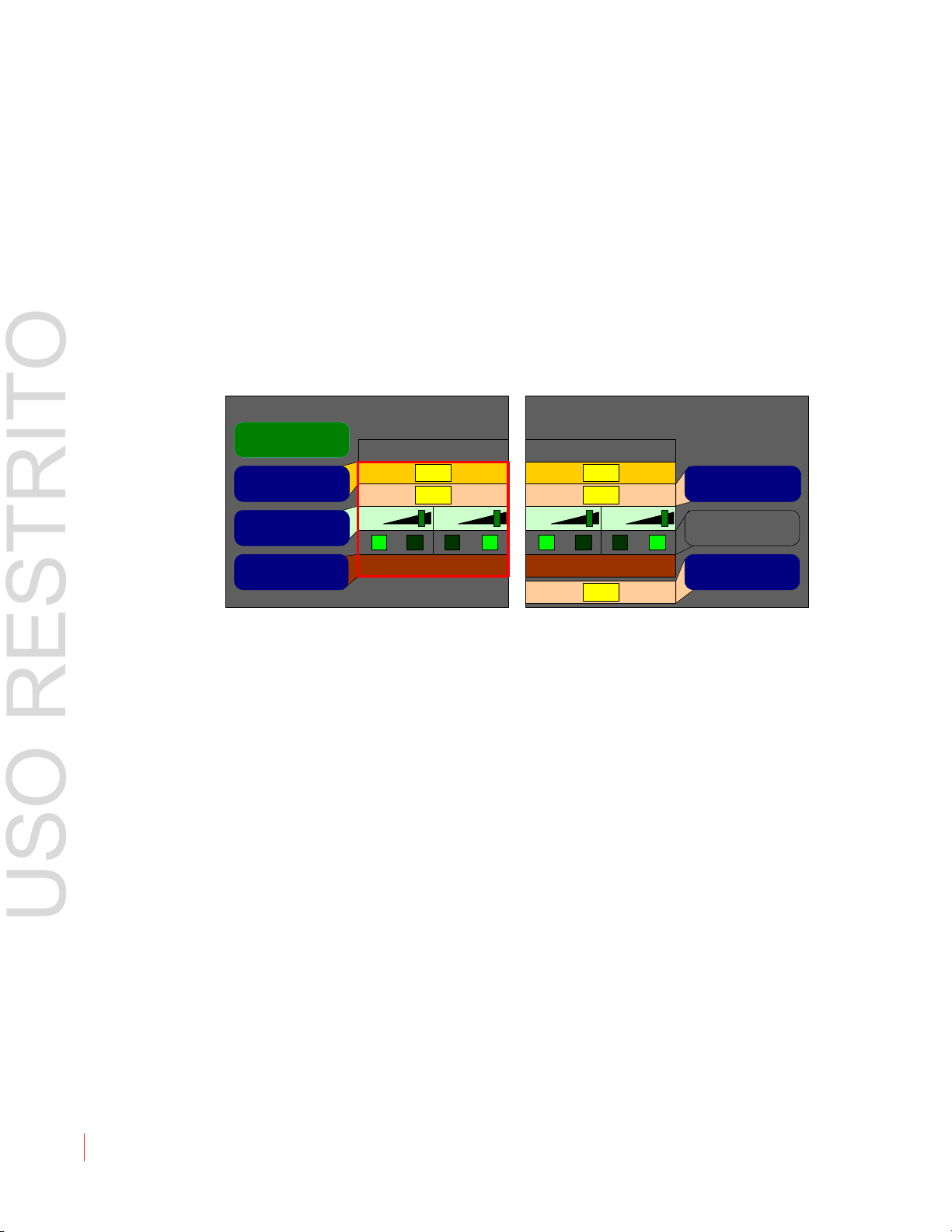
How do I Decode and Monitor a Dolby Bitstream (Continued)?
Now that you have connected a Dolby bitstream source to the Dolby
decoder, you need to connect the outputs of the Dolby decoder to the
metering channels you will be monitoring the audio on.
This step involves configuring the
Monitor Mixer Configuration
Menu:
1. Press the Select Monitor Pair control and then turn the Balance
knob to select the channel pair that you want the first decoded
Dolby pair to reside on. Note that the channel pairs scroll right and
left as you turn the Balance knob so that you can select any one of
the eight channel pairs.
2. Press the
Select Source Pair control and then turn the Balance
knob to select the decoded Dolby pair, as shown outlined in a red
box below.
Figure 2–4 Monitor Mixer Configuration Menu
3. Repeat Steps 1 and 2 for each decoded pair.
82 1 6 97 : AM P 1 -16 V S e r ie s U se r Gu i d e
© 2 0 1 3 W o h le r Te c h n o lo g i es , I n c . A l l ri g h ts r e s e r ved .
15
Ch ap te r 2 T h e “H ow D o I . . . ” C h ap te r
Configuration Selection
Menu
Main Screen
Menu
Screen Display
Menu
Screen Display Menu
Cluster Config Menu
Cluster Config
Menu
USO RESTRITO
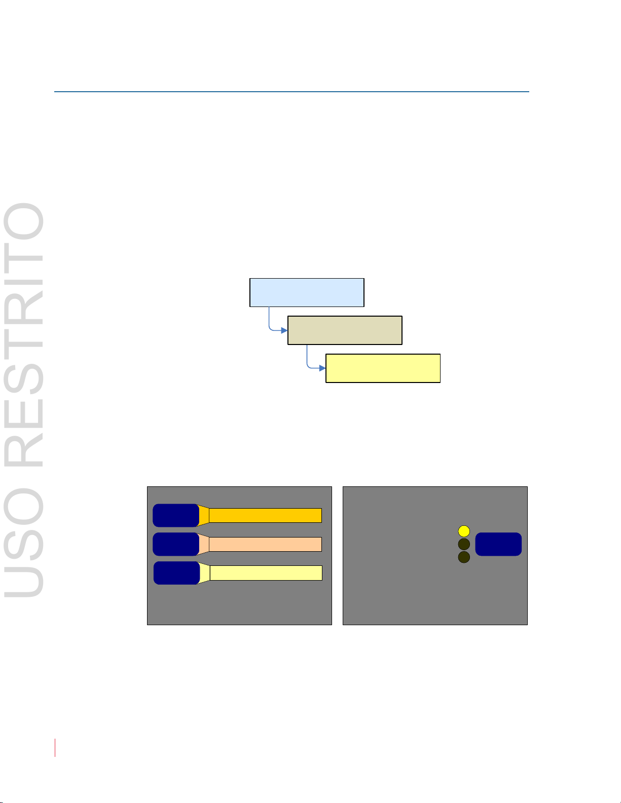
Fr eq u e n t l y A sk e d Q ue st io ns
4. For the Center and LFE channels, press the Speaker Assign knob
and then turn the Balance knob to select the dark R and L icons
and then press the Balance control to light them as shown in the
following figure. Then you will hear the Center and LFE channels
in both speakers.
5. Refer to the following section to cluster the 5.1 meter bars together.
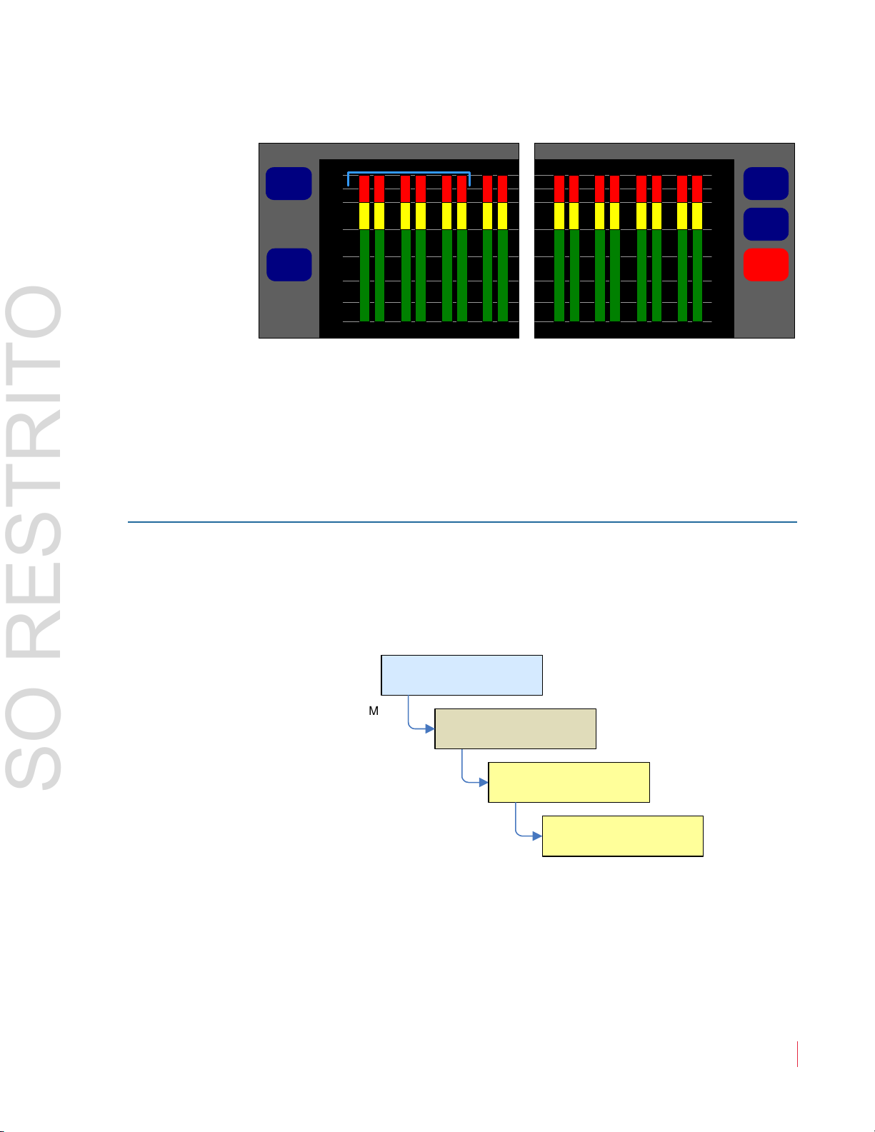
How do I Cluster Meter Pairs Together for Easy Readability?
Clustering the meter pairs in logical arrangements enhances the at-aglance readability of the meters. After setting up the meter clusters, you
can set up hot keys to solo each cluster. You can cluster the meters
together from the Cluster Configuration Screen:
16
1. Press the
Select Cluster knob and then turn the Balance knob to
select the channel pair that you want the cluster to start on. Note
that the blue bracket at the top selects.
2. Press the Cluster End control and then turn the Balance knob so
that the blue bracket encompasses the channel pairs you want in
the cluster. Press the Balance knob to set the cluster and see the
new arrangement.
3. Press the Edit Cluster Label knob to proceed to a screen that lets
you name the cluster. This name will appear on the Main Screen.
82 1 6 97 : AM P 1 -16 V S e r ie s U se r Gu i d e
© 2 0 13 W o h le r Tec h n ol o g i es , In c . A l l ri g h ts r e s e r ved .
Ch ap te r 2 The “How Do I...” Chapter
Cluster Configuration Menu
Edit
Label
Cluster
End
Cluster
Start
Select
Cluster
Default
2-4-8
-60
P
a
i
r
5
P
a
i
r
6
P
a
i
r
7
P
a
i
r
8
P
a
i
r
1
P
a
i
r
2
P
a
i
r
3
P
a
i
r
4
1 6
Configuration Selection
Menu
Main Screen
Menu
Screen Display
Menu
Screen Display Menu
Meter Config
Menu
Meter Config Menu
USO RESTRITO
Fr eq u e nt ly A sk ed Q ue st io ns
Figure 2–5 Cluster Configuration Menu
4. Press the E
dit Cluster Label knob to proceed to a screen that lets
you name the cluster. This name will appear on the Main Screen.
5. Refer to the following section to set up a hot key that will solo the
whole cluster.
How do I Customize the Meter Scales?
The AMP1-16V-MD contains a number of commonly-used meter
scales.
You can set the meter scale in the
Meter Configuration Menu:
1. Press the Scale control and then turn the Balance knob to select
your choice of meter scale.
2. If you want to change the ballistics, press the
then turn the Balance knob to select your new choice.
© 2 0 1 3 W o h le r Te c h n o lo g i es , I n c . A l l ri g h ts r e s e r ved .
82 1 6 97 : AM P 1 -16 V S e r ie s U se r Gu i d e
Ballistics knob and
17

Ch ap te r 2 T h e “H ow D o I . . . ” C h ap te r
Meter Configuration Menu
Set Default
-20 dBFS
15
-30 dBFS
12
4
0 dBr =
0 dBFS
Reference
Upper
Segment
Middle
Segment
Lower
Segment
AES
SingleFloat
VUBar
Scale
Ballistics
0
-60
-50
-40
-30
-10
-20
Configuration Selection
Menu
Main Screen
Menu
Screen Display
Menu
Screen Display Menu
Hot Key Menu
Main Screen Hot Key Button
Config Menu
USO RESTRITO
Fr eq u e n t l y A sk e d Q ue st io ns
3. If you would like to adjust the color-to-color transition points of
the meter segments, use the Upper Segment, Middle Segment,
and Lower Segment knobs. Pressing each control and then
turning the Balance knob, selects the color of the segment.
Pressing the Balance knob and then turning it will adjust the
transition point.
Figure 2–6 Meter Configuration Menu
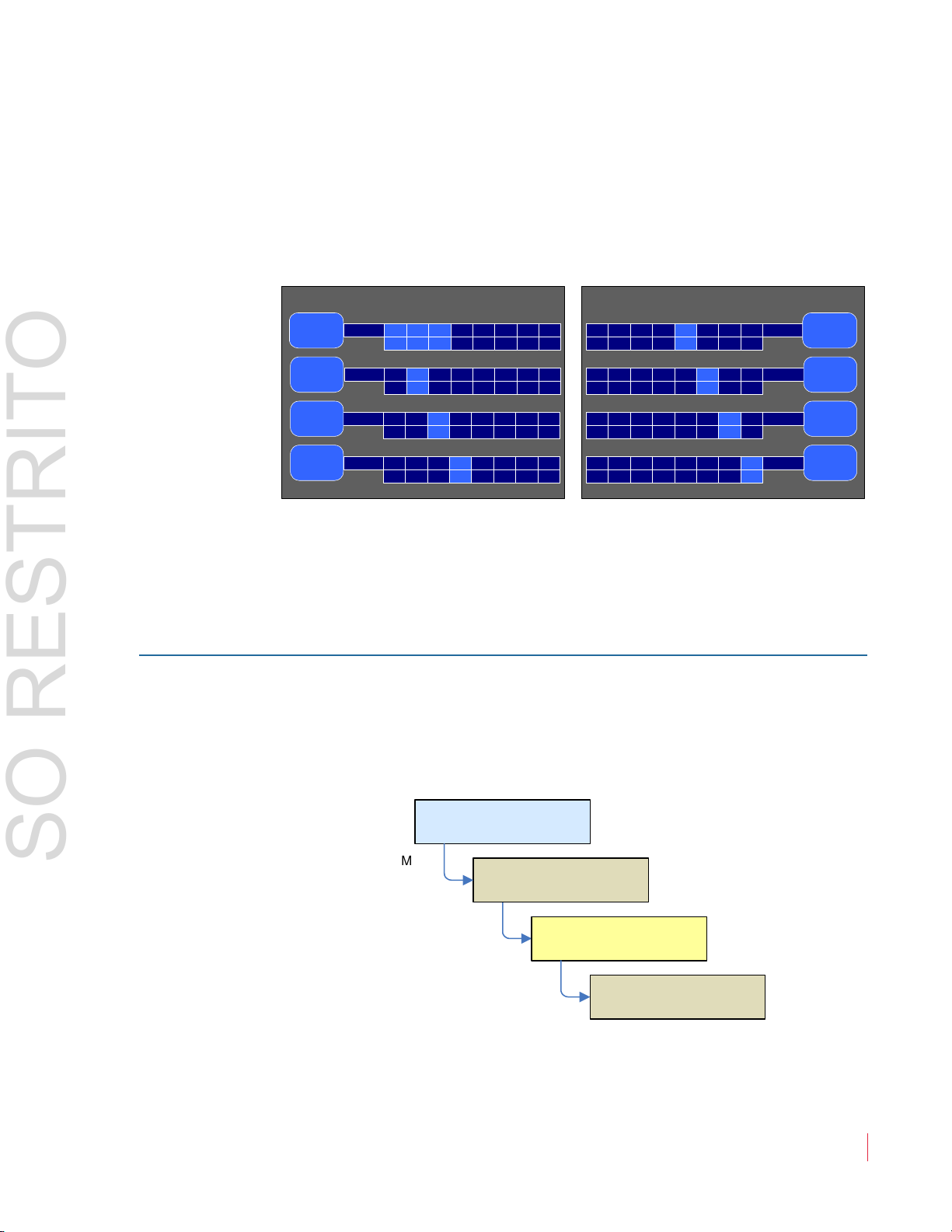
How do I Configure a Hot Key to Solo a Cluster?
By default each pair is a two-channel cluster and a hot key is set up for
each. But when other clusters are configured, such as a 5.1 channel
Dolby cluster, it makes sense to set up a
Setting up Solo hot keys is done in the Main Screen Hot Key
Configuration Menu:
Solo hot key for that.
18
82 1 6 97 : AM P 1 -16 V S e r ie s U se r Gu i d e
© 2 0 13 W o h le r Tec h n ol o g i es , In c . A l l ri g h ts r e s e r ved .
1. Press the button corresponding to the S
2. Turn the Balance knob to the type of hot key, and press the
Balance knob until Solo is selected and the control turns blue.
olo hot key to be set up.
Ch ap te r 2 The “How Do I...” Chapter
Main Screen Hot Key Button Configuration Menu
Button 4
Pair 4
Button 2
Pair 2
Button 1
Dolby 1
Button 7
Pair 7
2 4 6 8 10 12 14 16
1 3 5 7 9 11 13 15
2 4 6 8 10 12 14 16
1 3 5 7 9 11 13 15
Solo
Solo
2 4 6 8 10 12 14 16
1 3 5 7 9 11 13 15 Solo
2 4 6 8 10 12 14 16
1 3 5 7 9 11 13 15
2 4 6 8 10 12 14 16
1 3 5 7 9 11 13 15
Solo
Solo
Button 5
Pair 5
Button 6
Pair 6
Button 8
Pair 8
Button 3
Pair 3
Channels to Solo
Channels to Solo
Channels to Solo
Channels to Solo
Channels to Solo
2 4 6 8 10 12 14 16
1 3 5 7 9 11 13 15 Solo
Channels to Solo
2 4 6 8 10 12 14 16
1 3 5 7 9 11 13 15
2 4 6 8 10 12 14 16
1 3 5 7 9 11 13 15
Solo
Solo
Channels to Solo
Channels to Solo
Configuration Selection
Menu
Main Screen
Menu
Screen Display
Menu
Screen Display Menu
Hot Key Menu
Main Screen Hot Key Button
Config Menu
USO RESTRITO
Fr eq u e nt ly A sk ed Q ue st io ns
3. Turning the Balance knob again will let you highlight each
channel in order. Pressing the Balance knob lets you lighten or
darken each channel. Lighten each channel that you want as part
of the Solo and darken the others, as shown Figure 2–7 below.
Figure 2–7 Main Screen Hot Key Button
Configuration Menu
4. You can name the
Solo hot key by turning the Balance knob to
highlight the Solo label itself and then pressing the Balance
knob. This will proceed to the text labeling menu.
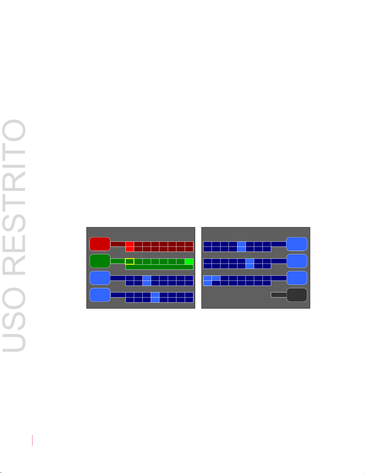
How do I Configure a Hot Key to Mute a Cluster?
Solo hot keys are part of the default configuration of the
AMP1-16V-MD. Sometimes it is convenient to also have some Mute
controls as well. You can set this up in the Main Screen Hot Key
Button Configuration Menu:
1. Press the hot key you want to be used to become a
Turn the Balance knob to highlight the type of hot key, and then
© 2 0 1 3 W o h le r Te c h n o lo g i es , I n c . A l l ri g h ts r e s e r ved .
82 1 6 97 : AM P 1 -16 V S e r ie s U se r Gu i d e
Mute button.
19
Ch ap te r 2 T h e “H ow D o I . . . ” C h ap te r
Main Screen Hot Key Button Configuration Menu
Button 4
Pair 4
Button 2
Alt Cfg
Button 1
Pair 1
Button 7
Front
2 4 6 8 10 12 14 16
1 3 5 7 9 11 13 15
Pre
Mute
2 4 6 8 10 12 14 16
1 3 5 7 9 11 13 15
2 4 6 8 10 12 14 16
1 3 5 7 9 11 13 15
1 2 3 4 5 6 7 8
Solo
Solo
2 4 6 8 10 12 14 16
1 3 5 7 9 11 13 15 Solo
Off
2 4 6 8 10 12 14 16
1 3 5 7 9 11 13 15
2 4 6 8 10 12 14 16
1 3 5 7 9 11 13 15
Solo
Solo
Button 5
Pair 5
Button 6
Pair 6
Button 8
Button 3
Pair 3
Preset to Recall
Channels to Mute
Channels to Solo
Channels to Solo
Channels to Solo
Channels to Solo
Channels to Solo
Selectable
USO RESTRITO
Fr eq u e n t l y A sk e d Q ue st io ns
press the Balance knob repeatedly until Mute is selected and the
control turns red.
2. Turn the Balance knob again to highlight the number of the first
channel you want to mute. Press the Balance knob to light up
your choice.
3. Repeat Step 3 until you have lit up all of the chann
els you want
this control to mute.
4. You can name the new hot key by turning the Balance knob to
highlight the button label itself and then pressing the Balance
knob. The hot key naming screen will then appear to allow you to
name the preset. Enter a name that is descriptive and that you will
recognize later.
Now, on the Main Screen, that same control will mute the channels
you selected.
Figure 2–8 Main Screen Hot Key Button
Configuration Menu
5. You can name the
20
82 1 6 97 : AM P 1 -16 V S e r ie s U se r Gu i d e
© 2 0 13 W o h le r Tec h n ol o g i es , In c . A l l ri g h ts r e s e r ved .
Mute hot key by turning the Balance knob to
highlight the Mute label itself and then pressing the Balance
knob. This will proceed to the text labeling menu.

Ch ap te r 2 The “How Do I...” Chapter
Configuration Selection
Menu
Main Scre en
Menu
AES Output
Menu
Configuration Selection
Menu
Main Screen
Menu
Analo g Output
Menu
AES Output Menu Analo g Output Menu
AES Output Configuration Menu
AES Output Channels 5/6 AES Output Channels 7/8
+0 +0 +0 +0
Level Trim
65 65 87 87
Affected by
Volume Control
Affected by
Solos & Mutes
Output Mute
With Headphone
AES Output =
Selected Sources
No
No
No
No
Yes
SDI In Channels 7/8SDI In Channels 3/4
Channel Output
AES Channel Pair
USO RESTRITO
Fr eq u e nt ly A sk ed Q ue st io ns
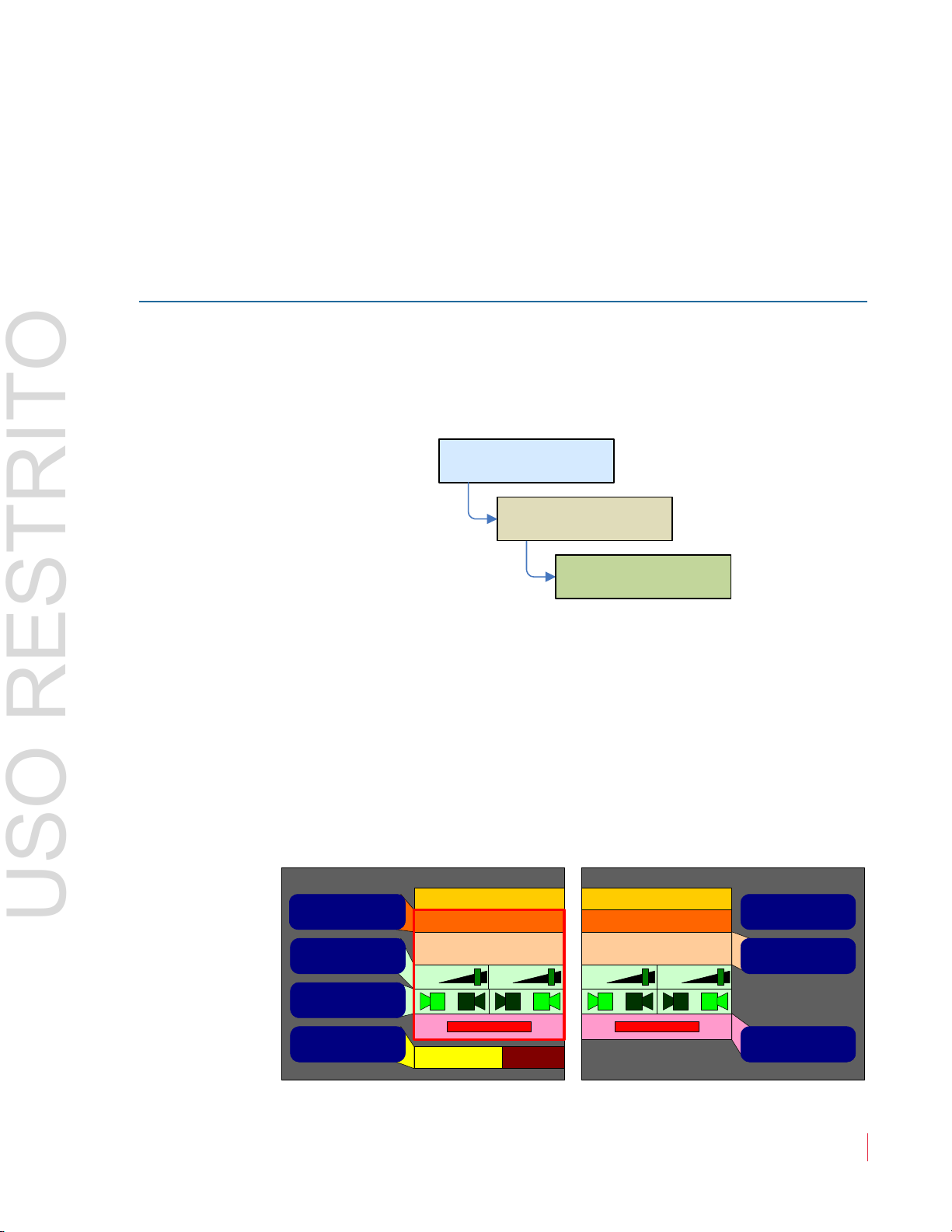
How do I Configure the AES and Analog Outputs?
You can use the AES and analog output ports to output selected signals
from the inputs: from the optional Dolby decoder, from the monitor
mix, or from the single monitor pair mixed to the speakers.
AES and Analog Output menus are very similar. To configure
The
one of them go to the AES Output Menu or Analog Output Menu as
shown:
There are two output modes: Selected Sources or Monitor
Channels. Press the upper left Output = button. Then toggle between
these two modes by pressing the Balance knob. In the example below,
we show the AES Output Configuration Menu, but the steps equally
apply to the Analog Output Configuration Menu.
Figure 2–9 AES Output Configuration Menu in
Selected Sources Mode
1. Press the Channel Pair button. Note that the channel pairs scroll
right and left as you turn the Balance knob so that you can select
any one of the eight AES channel pairs (or four analog channel
pairs).
© 2 0 1 3 W o h le r Te c h n o lo g i es , I n c . A l l ri g h ts r e s e r ved .
82 1 6 97 : AM P 1 -16 V S e r ie s U se r Gu i d e
21
Ch ap te r 2 T h e “H ow D o I . . . ” C h ap te r
AES Output Configuration Menu
AES Output Channels 5/6 AES Output Channels 7/8
+0 +0 +0 +0
Level Trim
Affected by
Volume Control
Affected by
Solos & Mutes
Output Mute
With Headphone
Channel Output
Yes
Yes
Yes
Yes
Yes
AES Output =
Monitor Channels
65 65 87 87
SDI In Channels 7/8SDI In Channels 3/4
AES Channel Pair
USO RESTRITO
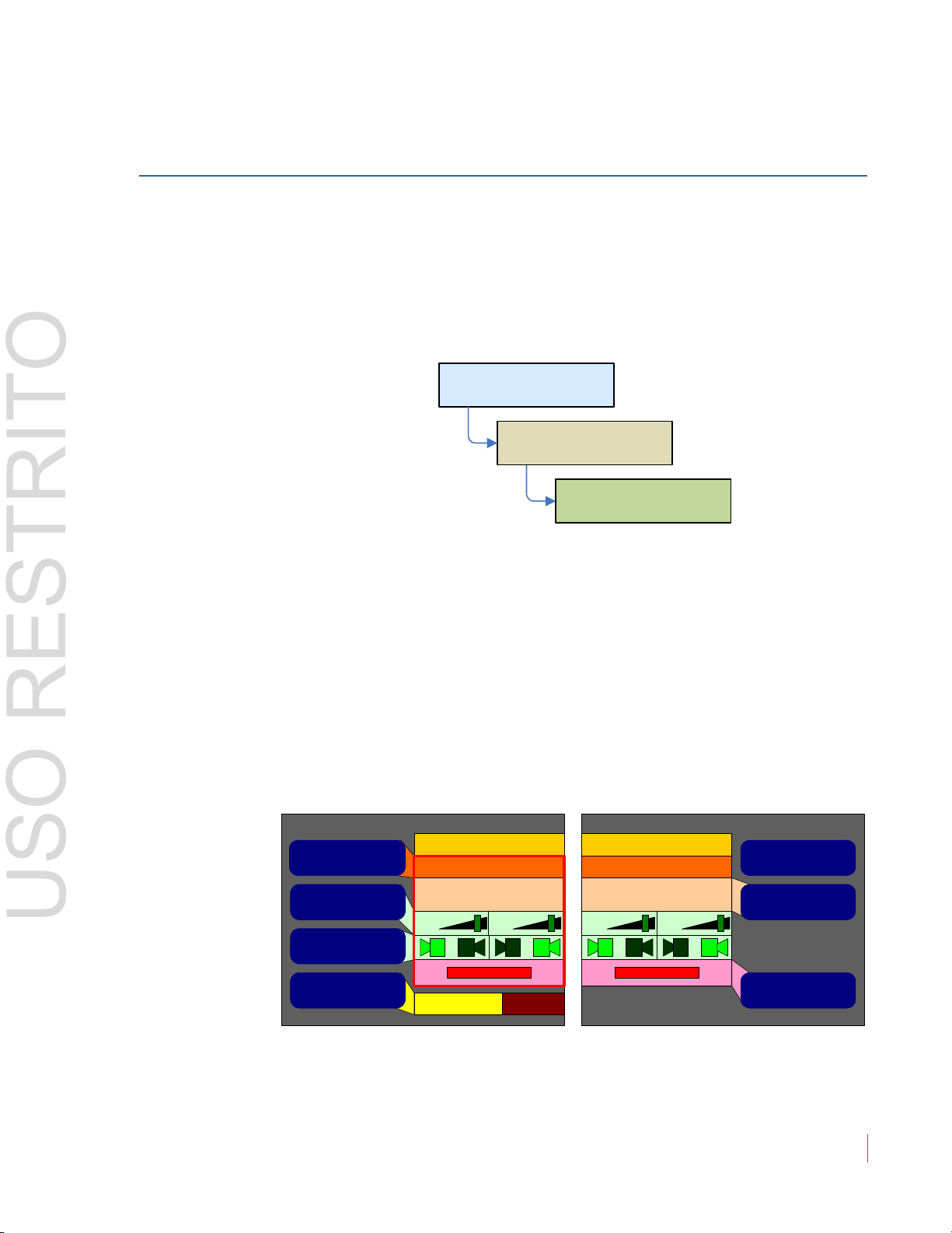
Fr eq u e n t l y A sk e d Q ue st io ns
2. Press the Output = Selected Sources button and turn the
Balance knob to select any of the SDI channel pairs, the Dolby
channel pairs, or the monitor mix channel pair.
3. Using the Level Trim and Channel Output buttons, you can
adjust what channels and signal level will be output.
4. Repeat Steps 1 through 3 for each of the output chan
nel pairs as
needed.
Figure 2–10 AES Output Configuration Menu in
Monitor Channels Mode
5. Press the
Channel Pair button. Note that the channel pairs scroll
right and left as you turn the Balance knob so that you can select
any one of the eight channel pairs (or 4 analog channel pairs).
22
82 1 6 97 : AM P 1 -16 V S e r ie s U se r Gu i d e
© 2 0 13 W o h le r Tec h n ol o g i es , In c . A l l ri g h ts r e s e r ved .
6. Press the Affected by Solos & Mutes button to toggle whether
each output channel pair can be controlled by the Solo and Mute
hot keys.
7. Press the Affected by Volume Control button to toggle whether
each output will be affected by the Volume and Balance controls.
8. Repeat steps 5 - 7 for each of the output channel pairs needed.
 Loading...