

Wohler AMP1-DA User Manual

AMP1-DA
1U Audio Speaker Monitor
with Two Selectable AES/EBU Digital Inputs
on BNCs, Two Analog Inputs on XLRs, Stereo
Analog Outputs on XLRs, Two 26-Segment
Level Meters, and Phase Indication
Document P/N 821530 Rev-C
User Manual
CONTENTS
Title and Contents ...........................................................................
1
Important Safety Instructions and Introduction ..............................................
Section 1: General Features and Specifications .............
Description, Features, and Applications ...................................................
Specifications and Other Options ..................................................................
Installation ....................................................................................................
Section 2: Operation ......................................................................
Front Panel Features ...................................................................................
Rear Panel Features .....................................................................................
Audio Amplifier and Speaker Configuration ..................................................
Balance Control Characteristics ....................................................................
Section 3: Technical Information ..........................................
General Technical Observations ....................................................................
AES Input D/A Conveter Module PCB Circuit Description ...........................
General Level Meter PCB Descriptions ........................................................
2
3
4
5
6
7
8
10
14
14
15
16
17
17
Series II Level Meter Rear Panel DIP Settings ..............................................
Series II Level Meter Internal DIP Settings ...................................................
Series II Level Meter Internal DIP Locations ................................................
Mute on Error Header H12 Location - 919117 PCB ....................................
AMP1-DA Interconnect Block Diagram .......................................................
© 2006 Wohler Technologies Inc. ALL rights reserved
18
19
20
21
22
1

Important Safety Instructions
1) Read these instructions.
2) Keep these instructions.
3) Heed all warnings.
4) Follow all instructions.
5) Do not use this apparatus near water.
6) Clean only with dry cloth.
7) Do not block any ventilation openings. Install in accordance with the manufacturer's instructions.
8) Do not install near any heat source such as radiators, heat registers, stoves, or other apparatus (including
amplifiers) that produce heat.
9) Do not defeat the safety purpose of the polarized or grounding-type plug. A polarized plug has two blades
with one wider than the other. A grounding type plug has two blades and a third grounding prong. The
wide blade or the third prong are provided for your safety. If the provided plug does not fit into your outlet,
consult an electrician for replacement of the obsolete outlet.
10) Protect the power cord from being walked on or pinched, particularly at plugs convenience receptacles
and the point where they exit from the apparatus.
11) Only use attachments/accessories specified by the manufacturer.
12) Use only with the cart stand, tripod, bracket, or table specified by the manufacturer, or sold with the
apparatus. When a cart is used, use caution when moving the cart/apparatus combination to avoid injury
from tip-over.
13) Unplug this apparatus during lightning storms or when unused for long periods of time.
14) Refer all servicing to qualified service personnel. Servicing is required when the apparatus has been
damaged in any way, such as when power-supply cord or plug is damaged, liquid has been spilled or
objects have fallen into the apparatus, the apparatus has been exposed to rain or moisture, does not
operate normally, or has been dropped.
15) Do not expose this apparatus to rain or moisture.
16) The apparatus shall be connected to a mains socket outlet with a protective earthing connection.
CAUTION!
In products featuring an audio amplifier and speakers, the surface at the side of the
unit, where the audio amplifier heat sink is internally attached, may get very hot after
extended operation. When operating the unit excercise caution when touching this
surface and ensure that external materials which may be adversely affected by heat
are not in contact with it. There is a Hot Surface label (see diagram) attached to the
aforementioned surface of the product.
Introduction
Congratulations on your selection of a Wohler Technologies product. We are confident it represents the best performance and value
available, and we guarantee your satisfaction with it.
If you have questions or comments you may contact us at:
Phone: (510) 870-0810 Fax: (510) 870-0811
www.wohler.com support@wohler.com
2
© 2007 Wohler Technologies, Inc. ALL rights reserved
Wohler Technologies, Inc.
31055 Huntwood Avenue
Hayward, CA 94544
US Toll-Free: 1-888-596-4537

AMP1-DA User Manual P/N 821530 Rev-C
General Features
and Specifications
Section 1
Description
Features
Applications
Specifications
Other Options
© 2006 Wohler Technologies Inc. ALL rights reserved
12/01/06
3
AMP1-DA User Manual P/N 821530 Rev-C
Section 1: General Features and Specifications
AMP1-DAMP1-D
AMP1-D
AMP1-DAMP1-D
AA
A
AA
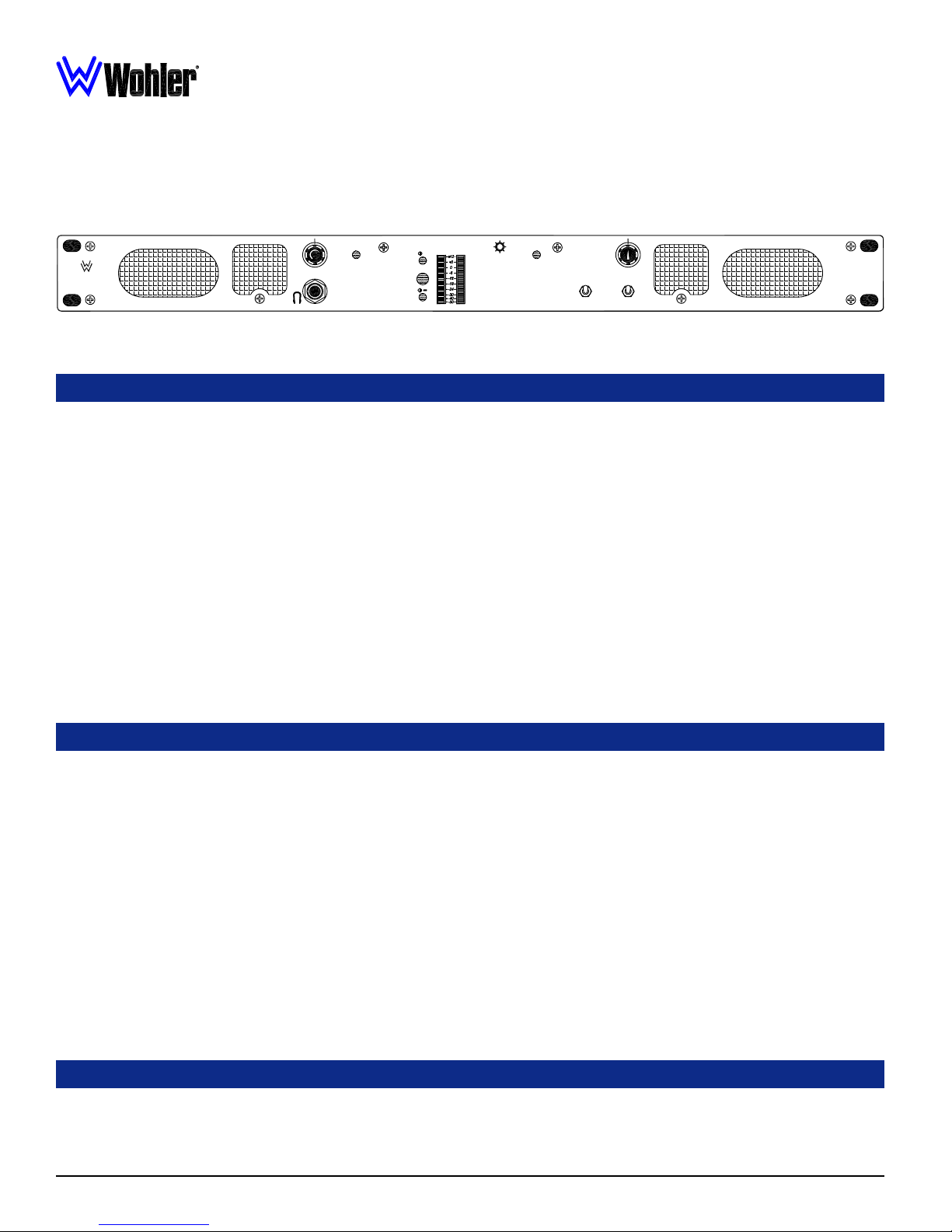
1U Digital/Analog Audio Stereo Speaker Monitor
WOHLER
TECHNOLOGIES
POWER
SOURCE
+
AVG
12
AMP1-DA Front Panel
AES
ANALOG
AES1
AES2
DIGITAL
AMP1-DA
DIGITAL AUDIO
MONITOR PANEL
Description
The AMP1 Digital series of audio monitors provides self-powered, full-fidelity stereo monitoring in the smallest rack space
possible. All models contain four high performance transducers driven by three power amplifiers: two amplifier/driver combinations
handle midrange and high frequency information in stereo, while the third center channel reproduces information below the 500 Hz
crossover point.
All AMP1 Digital models come equipped with a ganged stereo volume control and balance pot, power indication LED, and
headphone output. Output limiter circuits are incorporated to protect the speakers, and extensive magnetic shielding allows
placement immediately adjacent to video monitors without causing display interference.
The AMP1-DA model features two selectable AES input sources on unbalanced BNC connectors and a stereo analog input source
on two balanced XLR connectors. A toggle switch on the front panel allows selection of AES source 1 or 2 while another toggle
switch selects between the selected AES digital source and the analog source inputs. A red LED indicates the presence and error
status of the selected AES signal entering the unit.
Two high-resolution 26-segment tri-color LED bargraph level meters display the audio levels for the left and right selected sources
and our proprietary three-LED stereo phase indication feature allows monitoring of phase relationships of the selected stereo inputs.
An additional pair of XLR connectors are provided on the rear panel for outputing an analog signal of the selected sources for
connecting to downstream equipment.
Features
• 98 dB SPL at two feet
• Only one rack space high
• Audible and visual indication of phase/polarity problems
• Thorough magnetic shielding for placement next to video monitors
• Two selectable AES/EBU inputs on unbalanced BNC connectors
• Analog stereo inputs on two balanced XLR connectors
• Analog output of selected input on two balanced XLR connectors
• AES input signal status indication LED
• AES source selection via front panel toggle switch
• Digital/analog source selection via front panel toggle switch
• Headphone output
• Power indication LED
• Two 26-segment high-resolution tri-color bargraph level meters
• Selectable input Referrence Level (0, +4, +6, or +8 dBu)
• Selectable Display Mode (VU Only, VU/PPM, or PPM Only)
• Selectable Peak Hold (Manual, 3-Second, 10-Second, or Off)
• Selectable PPM Ballistics (Type I, Type II, DIN 45406, or SSRT)
• Selectable alternate Bargraph Scales (AES, Extended VU,
Alternative AES, VU, BBC, NORDIC, and DIN)
Applications
The AMP1 Digital series is ideally suited for use in VTR bays, mobile production vehicles, teleconferencing installations,
multimedia systems, satellite links and cable TV facilities, and on-air radio studios. Designed and manufactured in the U.S., the
AMP1-DA is backed by a strong warranty and a satisfaction guaranteed return policy.
4
© 2006 Wohler Technologies Inc. ALL rights reserved
AMP1-DA User Manual P/N 821530 Rev-C
Section 1: General Features and Specifications
General Specifications
Input connectors:
Input impedance:
Input Level for Maximum
Output (Volume Full On):
Input Overload:
Peak Acoustic Output
(@ 2 ft.):
Response, Sixth Octave:
Power output
ΩΩ
Ω):
ΩΩ
ΩΩ
Ω):
ΩΩ
dledle
-distance-distance
dle
-distance
dledle
-distance-distance
RMS Each Side (4
RMS Bass (4
Distortion, Electrical:
Distortion, Acoustic:
Medium-size SegmentsMedium-size Segments
Medium-size Segments
Medium-size SegmentsMedium-size Segments
(f(f
or Midor Mid
(f
or Mid
(f(f
Hum and Noise:
Magnetic Shielding:
or Midor Mid
XLR (3-pin female) 2 each
BNC (female) 2 each
XLR (Analog): 40K Ω balanced
BNC (Digital): 75 Ω unbalanced
0 dBv balanced
+26 dBv balanced
98 dB SPL
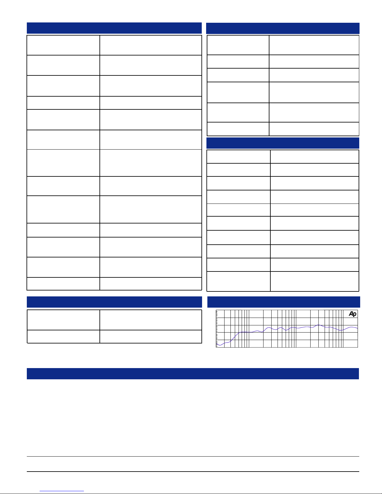
80 Hz - 16 kHz ± 7 dB)
(-10 dB @ 50 Hz, 22 kHZ)
10 W transient / 5 W continuous
20 W transient / 10 W continuous
Less than 0.15% at any level below
limit threshold
8% or less at worst case frequencies
above 180 Hz including cabinet
resonance; typically less than 2%
VV
ieie
wingwing
V
ie
wing
VV
ieie
Better than -68 dB below full output
Less than 1 Gauss any adjacent
surface
wingwing
Digital/Analog Specifications
D to A gain calibration,
(dB = dBFS):
AES sampling rate:
D to A converter:
Converted analog out:
(S/N):
Converted analog out:
(THD):
AES Termination:
+8 = -20, +4 = -20, +6 = -9,
0 = -18 (DIP selectable)
32-48 KHz, auto-select
24-bit low jitter
>90 dB
< 0.008%
Removable (DIP select)
Level Meter Specifications
Level Meter Type:
Bargraph Quantity:
LED Color:
Metering Range:
Reference Level Select:
Display Mode Select:
Peak Hold Select:
PPM Ballistics Select:
26-segment tri-color LED bargraph
2 each, vertical
Tricolor (red, amber, green)
65 dB
0, +4, +6, or +8 dBv
VU Only, VU/PPM, or PPM Only
Manual, 3-sec, 10-sec, or OFF
Type I, Type II, DIN 4506, or SSRT
Power Consumption
(Average Maximum):
AC Mains input:
Physical Specifications
Dimension (h x w x d):
Weight:
35 W
100-240VAC, 50-60 Hz
1.75 x 19 x 12 inches
44.5x 483 x 298 mm
14 lbs. (6.4 kg)
Calibration:
Scale Select:
+10
0
d
B
-10
-20
-30
Typical 1/6 Octave Audio Response Curve
Auto
AES, Extended VU, Alternate AES,
VU, BBC, NORDIC, or DIN
Audio Response
Hz
10k5k2k1k50020010050 20k20
Other Options
Wohler Technologies offers the broadest range of standard production audio monitor units. Standard-production models or special order
custom features for the AMP1 Digital Series (1U) units include the following functions (and combinations thereof):
• SDI (SMPTE259) inputs
• Separate channel volume controls
• Mono, mute, and mode switches
• Alternate level meter scales and color maps
• Transformer coupled analog inputs
• FULL output power DC operation
• External speaker capability
• Multiple input and output connector type choices
Other custom options are possible. Call your dealer or Wohler Technologies to discuss your specific needs.
Units are designed to meet, at time of manufacture, all currently applicable product safety and EMC requirements, such as those of UL
and CE. 0 dbV ref. 0.775V RMS. Features and specifications subject to improvement without notice.
© 2006 Wohler Technologies Inc. ALL rights reserved
5

AMP1-DA User Manual P/N 821530 Rev-C
Section 1: General Features and Specifications
Installation
Mounting
The unit should be mounted where convenient for operating persons, ideally at approximately ear/eye level for best high frequency
response and visual observation of the level meters. Its superior magnetic shielding eliminates concerns about locating it adjacent to
most types of CRT monitors, including even high-resolution color monitors.
NOTE: Be sure to set the level meter Input Level Gain Calibration and VU/PPM Display Mode DIP switch (accessed through the top
cover) BEFORE installing the unit into an enclosed rack or console. See page 17 for setting information.
Heat Dissipation
Heat dissipated by the speaker amps is conducted directly to the left side of the chassis; no special considerations for cooling are
necessary as long as the ambient temperature inside the rack area does not exceed approximately 40°C (104°F).
Sympathetic Vibration
Sympathetic vibration from other equipment (cables, etc.,) in the rack may be serious enough to interfere with the unit’s sound quality
out in the listening area. The use of thin card stock and/or felt or foam weather-stripping type materials between adjacent vibrating
surfaces, or tying up loose cables, etc., may be required to stop vibrations external to the unit.
Mechanical Bracing
Even though the unit is fairly heavy, the chassis is securely attached to the front panel at eight points along its surface, not just at
the four corners of the chassis ears. This feature will reduce or eliminate rear bracing requirements in many mobile/portable applications. The weight of internal components is distributed fairly evenly around the unit.
Audio Connections
Connection of the audio feeds is straightforward. Please refer to the system interconnect block diagrams on pages 20 and 21 for
clarification of the general signal paths into and out of the AMP2A and AMP2A-2S units.
Analog inputs via the 3-pin female XLR connectors are configured for 200K Ω balanced connections. RCA connector inputs
(AMP2A only) are configured for 47K Ω unbalanced connections.
Electrical Interference
Care should be exercised to avoid mismatched cable types and other similar causes of undesired reflections in RF signal systems. If
severe enough, such reflections can result in undesirable electrical interference in the audio signals.
As with any audio equipment, maximum immunity from electrical interference requires the use of shielded cable; however, satisfactory
results can sometimes be obtained without it. The internal circuitry common is connected to the chassis.
AC Power
The unit's AC mains connection is via a standard IEC inlet, with safety ground connected directly to the unit's chassis. The universal
AC input (100-240VAC, 50/60Hz) switching power supply is a self-resetting sealed type, with automatic over-voltage and over-current
shutdown. There is no user-replaceable fuse in either the primary or secondary circuit.
6
© 2006 Wohler Technologies Inc. ALL rights reserved

AMP1-DA User Manual P/N 821530 Rev-C
Audio Amplifier and Speaker Configuration
Balance Control Characteristics
Section 2
Operation
Front Panel Features
Rear Panel Features
© 2006 Wohler Technologies Inc. ALL rights reserved
7

AMP1-DA User Manual P/N 821530 Rev-C
Section 2: Operation
Front Panel Features
Please refer to Figure-2a on the following page to familiarize yourself with the front panel features of the AMP1-DA unit. The following
sections describe these functions and are referenced, by number, to Figure-2a.
Speakers
1
1
The AMP1-DA internal speaker system is comprised of two mid-range tweeter speakers (left and right) and two woofer speakers
(left and right). The two mid-range speakers reproduce, in stereo, only the mid and high frequencies, while the two woofer speakers
monorally reproduce the low frequencies. See page 14 for more information about the speaker configuration of the AMP1 Series.
Volume Control
2
This controls the loudness of the audio reproduced by the internal speakers or connected headphone. Clock-wise rotation of this
control increases the loudness of the monitored audio.
Headphone Jack
3
Select the headphone audio sources as you would for the internal speakers. When you plug in headphones, the internal speakers will
mute. This jack accepts a standard "mini" stereo (ring/tip/sleeve) plug.
Power Indication LED
4
This LED glows green to indicate the unit is connected to operational mains power.
Phase Indication LEDs
5
These three LEDs offer instant visual verification of phase (polarity) conditions in the pair of channels selected for monitoring in the
ΦΦ
Left/Right channel speakers. The two smaller LEDs, labeled
in the signal, while the larger center LED, labeled AVG, indicates the average phase condition.
The small top
for out-of-phase signals. The larger AVG LED indicates the average phase condition by glowing GREEN for in-phase conditions,
or RED for out-of-phase conditions.
In general, it is sufficient to regard the AVG LED (average phase condition) as adequate for proper phase monitoring. While it is
normal for stereo signals to contain some intermittant instantaneous out-of-phase and in-phase conditions (small LEDs), a steady
red glow of the larger LED almost always indicates an out-of-phase alarm condition.
ΦΦ
Φ+ LED glows (or blinks) GREEN when signals are in-phase. The small bottom
ΦΦ
ΦΦ
Φ+ and
Φ- (above and below), show instantaneous phase relationships
ΦΦ
ΦΦ
ΦΦ
Φ- LED glows (or blinks) AMBER
ΦΦ
Audio Level Meters
6
Audio levels for the selected input sources are displayed via these two 26-segment tri-color (GREEN, AMBER, RED) LED
bargraph display level meters.
These two bargraph displays feature an Auto-Calibration feature and are user adjustable for Display Mode and Reference Level
via a rear panel DIP module (Item F, page 12). Peak Hold, PPM Ballistics, and Alternative Scales can be set via an internal
DIP module. See pages 18 and 19 for more information regarding these DIP switch module locations and settings.
AES/EBU Signal Status Indication LED
7
This LED indicates the status of the currently selected AES digital signal (AES1 or AES2) regardless of any other monitor
selection settings.
This LED glows GREEN as long as a valid AES digital datastream is being received. It will glow RED to indicate errors in the
reception of the AES signal. There are two DIP switch selectable modes of fault detection that will create a RED LED error
indication. Please see Item B, page 10 for more information about this setting.
An additional feature of the AES signal error detection is the ability to mute the audio when errors are detected in the AES signal. To
enable this feature, a jumper is placed at H12 of the 919117 PCB. See page 21 for location of H12 on the 919117 PCB.
Digital Source Select Switch
8
This switch selects between the two AES/EBU IN (IN1 or IN2) source inputs (Item C, page 10). Note that for the selected AES
source to be monitored, the Analog/Digital Source Select Switch (Item 9) must be set to DIGITAL.
Analog/Digital Source Select Switch
9
When this toggle switch is set to ANALOG, the unit will monitor the analog input signals from the ANALOG IN XLR connectors
on the rear panel (Item G, page 14). When this toggle switch is set to DIGITAL, the unit will monitor the selected AES/EBU IN
input (IN1 or IN2) on the rear panel (Item C, page 10).
Balance Control
10
This pans the volume balance between the left and right speakers. See page 14 for more information about the balance control
characteristrics of the AMP1 Series.
Bargraph Brightness Adjust
11
This control is recessed into the front panel and can be accessed using a small flathead screwdriver. Turning the trim pot clockwise
will simultaneously increase the relative brightness of the LED segments in both bargraphs.
8
© 2006 Wohler Technologies Inc. ALL rights reserved
 Loading...