

Wohler AMP1A-4S, AMP1A-10S, AMP1A-LP4S, AMP1A-LP10S User Manual

AMP1A Series
AMP1A-4S AMP1A-10S AMP1A-LP4S AMP1A-LP10S
1U Multi-Channel Audio Speaker Monitors
with Four or Ten Analog Audio Inputs,
Stereo Analog Outputs, and Optional Dual
10-Segment Level Meters and Phase Indication
Document P/N 821527 Rev-B
User Manual
CONTENTS
Title and Contents ...........................................................
Important Safety Instructions and Introduction ..........................................
Section 1: General Features and Specifications........
Description and Features ......................................................................
Applications, General Specifications, and Other Options ...........................
Installation ..............................................................................................
Section 2: Operation ..................................................................
Front Panel Features ...............................................................................
Rear Panel Features .................................................................................
Section 3: Technical Information .......................................
General Technical Observations ...............................................................
Level Meter Gain Calibration and Display Mode Settings .........................
1
2
3
4
5
6
7
8
10
13
14
15
Bargraph Driver Circuit Description (919017) ..........................................
Level Meter Specifications .......................................................................
Multi-Channel Analog Switching PCB Circuit Description (919013) .........
Interconnect Block Diagrams ..................................................................
© 2006 Wohler Technologies Inc. ALL rights reserved
16
16
17
18
1

Important Safety Instructions
1) Read these instructions.
2) Keep these instructions.
3) Heed all warnings.
4) Follow all instructions.
5) Do not use this apparatus near water.
6) Clean only with dry cloth.
7) Do not block any ventilation openings. Install in accordance with the manufacturer's instructions.
8) Do not install near any heat source such as radiators, heat registers, stoves, or other apparatus (including
amplifiers) that produce heat.
9) Do not defeat the safety purpose of the polarized or grounding-type plug. A polarized plug has two blades
with one wider than the other. A grounding type plug has two blades and a third grounding prong. The
wide blade or the third prong are provided for your safety. If the provided plug does not fit into your outlet,
consult an electrician for replacement of the obsolete outlet.
10) Protect the power cord from being walked on or pinched, particularly at plugs convenience receptacles
and the point where they exit from the apparatus.
11) Only use attachments/accessories specified by the manufacturer.
12) Use only with the cart stand, tripod, bracket, or table specified by the manufacturer, or sold with the
apparatus. When a cart is used, use caution when moving the cart/apparatus combination to avoid injury
from tip-over.
13) Unplug this apparatus during lightning storms or when unused for long periods of time.
14) Refer all servicing to qualified service personnel. Servicing is required when the apparatus has been
damaged in any way, such as when power-supply cord or plug is damaged, liquid has been spilled or
objects have fallen into the apparatus, the apparatus has been exposed to rain or moisture, does not
operate normally, or has been dropped.
15) Do not expose this apparatus to rain or moisture.
16) The apparatus shall be connected to a mains socket outlet with a protective earthing connection.
CAUTION!
In products featuring an audio amplifier and speakers, the surface at the side of the
unit, where the audio amplifier heat sink is internally attached, may get very hot after
extended operation. When operating the unit excercise caution when touching this
surface and ensure that external materials which may be adversely affected by heat
are not in contact with it. There is a Hot Surface label (see diagram) attached to the
aforementioned surface of the product.
Introduction
Congratulations on your selection of a Wohler Technologies product. We are confident it represents the best performance and value
available, and we guarantee your satisfaction with it.
If you have questions or comments you may contact us at:
Phone: (510) 870-0810 Fax: (510) 870-0811
www.wohler.com support@wohler.com
2
© 2007 Wohler Technologies, Inc. ALL rights reserved
Wohler Technologies, Inc.
31055 Huntwood Avenue
Hayward, CA 94544
US Toll-Free: 1-888-596-4537

AMP1A-4S/-10S/-LP4S/-LP10S User Manual P/N 821527 Rev-B
Section 1
General Features
and Specifications
Description
Features
Applications
General Specifications
Other Options
© 2006 Wohler Technologies Inc. ALL rights reserved
3
AMP1A-4S/-10S/-LP4S/-LP10S User Manual P/N 821527 Rev-B
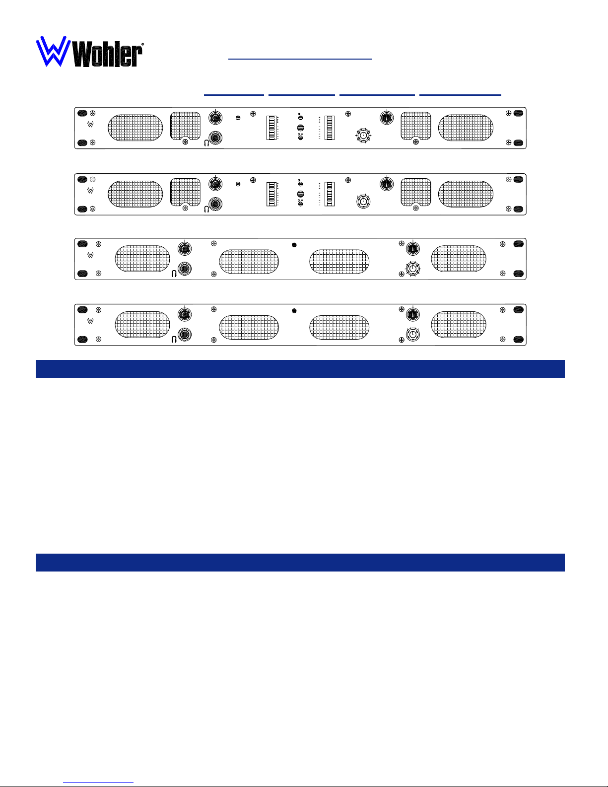
AMP1A SeriesAMP1A Series
AMP1A Series
AMP1A SeriesAMP1A Series
1U Stereo Analog Audio Speaker Monitors
Including Models: AMP1A-4S AMP1A-10S AMP1A-LP4S AMP1A-LP10S
Section 1: General Features and Specifications
SOURCE
+
3
2
1
AVG
0
1
3
5
7
10
20
SOURCE
5
6
4
7
3
8
9
2
2
1
10
AMP1A-LP10S
ANALOG AUDIO
MONITOR PANEL
WOHLER
TECHNOLOGIES
POWER
SOURCE
1
3
2
1
0
1
3
5
7
10
20
AMP1A-LP10S
SOURCE
+
3
2
1
AVG
0
1
3
5
7
10
2020
SOURCE
2
3
41
AMP1A-LP4S
ANALOG AUDIO
MONITOR PANEL
WOHLER
TECHNOLOGIES
POWER
SOURCE
3
2
1
0
1
3
5
7
10
1 2
AMP1A-LP4S
POWER
AMP1A-10S
WOHLER
TECHNOLOGIES
SOURCE
65
4
7
3
8
92
10
1
ANALOG AUDIO
MONITOR PANEL
AMP1A-10S
POWER
WOHLER
TECHNOLOGIES
SOURCE
2
3
41
AMP1A-4S
ANALOG AUDIO
MONITOR PANEL
AMP1A-4S
Description
The AMP-1A Series of audio monitors provides self-powered, full-fidelity stereo monitoring in the smallest rack space possible. All
models in the AMP1A Series contain five high performance transducers driven by three power amplifiers: two amplifier/driver
combinations handle midrange and high frequency information in stereo, while the third center channel reproduces information
below the 500 Hz crossover point.
All AMP-1A models come equipped with a ganged stereo volume control and balance pot, power indication LED, and headphone
output. Output limiter circuits are incorporated to protect the speakers, and extensive magnetic shielding allows placement
immediately adjacent to video monitors with no color impurities.
The AMP1A-4S model features four pairs (8 channels) of balanced inputs on Phoenix connectors and the AMP1A-10S features ten
pairs (20 channels) of these inputs. Any pair of inputs is selectable for monitoring via a rotary source select switch on the front
panel. An additional pair of XLR connectors output the selected audio signals for connecting to downstream equipment.
The AMP1A-LP4S and AMP1A-LP10S models offer the same input features as the -4S and -10S models with the addition of dual 10segment tri-color LED bargraph level meters and Wohlers' proprietary three-LED stereo phase indication feature.
Features
• 98 dB SPL at two feet
• Only one rack space high
• Excellent high frequency response for positive detection
of background whine and noise
• Audible indication of phase/polarity problems
• Thorough magnetic shielding for placement next to video
monitors
• Numerous control and input options
• Quick and easy installation: simply slide in the rack and connect
audio and AC power
• 4S and 10S models offer front panel switching between four (8
channels) or ten (20 channels) stereo inputs.
• LP models offer dual level meters and stereo phase indication
LEDs
4
© 2006 Wohler Technologies Inc. ALL rights reserved

AMP1A-4S/-10S/-LP4S/-LP10S User Manual P/N 821527 Rev-B
Section 1: General Features and Specifications
Applications
The AMP1A Series is ideally suited for use in VTR bays, mobile production vehicles, teleconferencing installations, multimedia
systems, satellite links and cable TV facilities, and on-air radio studios. Designed and manufactured in the U.S., the AMP1A Series is
backed by a strong warranty and a satisfaction guaranteed return policy.
General Specifications
Input impedance:
Input Level for Maximum
Output (Volume Full On):
Input Overload:
Peak Acoustic Output
(@ 2 ft.):
Response, Sixth Octave:
Power output
RMS Each Side:
RMS Bass:
Distortion, Electrical:
Distortion, Acoustic:
Hum and Noise:
90K Ω (Ohm) balanced
0 dBv balanced
+26 dBv balanced
98 dB SPL
80 Hz - 16 kHz ± 7 dB)
(-10 dB @ 50 Hz, 22 kHZ)
10 W transient / 5 W continuous
20 W transient / 10 W continuous
Less than 0.15% at any level below
limit threshold
8% or less at worst case frequencies
above 180 Hz including cabinet
resonance; typically less than 2%
Better than -68 dB below full output
Level Meter Specifications (-LP)
Level Calibration:
Frequency Response:
Level Meter Type:
LED Color:
Metering Range:
Display Modes:
VU Characteristics,
Rise Time:
Decay Time:
PPM Characteristics,
Attack Time:
Decay Time:
-6, 0, +4, +8 dBv
20 Hz to 18 kHz (±0.5 dB)
10-segment tri-color LED bargraph
display
Tricolor (red, amber, green)
23 dB
VU or PPM, Selectable
300 ms to 99% of full indication
300 ms
10 ms
2 seconds, 0 to -20 dB
Physical Specifications
Dimension (h x w x d):
1.75 x 19 x 12 inches
44.5x 483 x 298 mm
Magnetic Shielding:
Input Connectors:
Power Consumption
(Average Maximum):
AC Mains input:
`
Medium-size SegmentsMedium-size Segments
Medium-size Segments
Medium-size SegmentsMedium-size Segments
(f(f
or Midor Mid
(f
or Mid
(f(f
or Midor Mid
dledle
-distance-distance
dle
-distance
dledle
-distance-distance
Less than 1 Gauss any adjacent
surface
VV
ieie
wingwing
V
ie
wing
VV
ieie
wingwing
Balanced: XLR
35 W
100-240VAC, 50-60 Hz
Weight:
+10
0
d
B
-10
-20
-30
14 lbs. (6.4 kg)
Audio Response
Hz
Typical 1/6 Octave Audio Response Curve
10k5k2k1k50020010050 20k20
Other Options
Wohler Technologies offers by far the broadest range of standard production audio monitor units. Standard-production models or
special order custom features for the AMP1A Series (1U) units include the following functions (and combinations thereof):
• Multiple stereo input selection, from 2 to 10
• AES/EBU and SDI (SMPTE259) inputs
• Separate channel volume controls
• Mono, mute, and mode switches
• Alternate level meter scales and color maps
Other custom options are possible. Call your dealer or Wohler Technologies to discuss your specific needs.
• High resolution 26-segment bargraph level meters
• Transformer coupled inputs
• FULL output power DC operation
• External speaker capability
• Multiple input and output connector type choices
Units are designed to meet, at time of manufacture, all currently applicable product safety and EMC requirements, such as those of CE.
0 dbV ref. 0.775V RMS. Features and specifications subject to improvement without notice.
© 2006 Wohler Technologies Inc. ALL rights reserved
5

AMP1A-4S/-10S/-LP4S/-LP10S User Manual P/N 821527 Rev-B Section 1: General Features and Specifications
Installation
Mounting
NOTE: Be sure to set the level meter Gain Calibration and Display Mode DIP switch (accessed through the top cover) BEFORE
installing the unit in the rack or console. See page 15 for setting information.
The unit should be mounted where convenient for operating persons, ideally at approximately ear level for best high frequency
response. Its superior magnetic shielding eliminates concerns about locating it adjacent to most types of CRT monitors, including
even high-resolution color monitors.
Heat Dissipation
Heat dissipated by the speaker amps is conducted directly to the left side of the chassis; no special considerations for cooling are
necessary as long as the ambient temperature inside the rack area does not exceed approximately 40°C (104°F).
Sympathetic Vibration
Sympathetic vibration from other equipment (cables, etc.), in the rack may be serious enough to interfere with the unit’s sound
quality out in the listening area. The use of thin card stock and/or felt or foam weather-stripping type materials between adjacent
vibrating surfaces, or tying up loose cables, etc., may be required to stop vibrations external to the unit.
Mechanical Bracing
Even though the unit is fairly heavy, the chassis is securely attached to the front panel at eight points along its surface, not just at
the four corners of the chassis ears. This feature will reduce or eliminate rear bracing requirements in many mobile/portable
applications. The weight of internal components is distributed fairly evenly around the unit.
Audio Connections
Connection of the audio feeds is straightforward. Please refer to the system interconnect block diagram on pages 18 and 19 for
clarification of the general signal paths into and out of the AMP1A Series units.
Phoenix connector inputs on the analog switching PCB (919013) are 90K Ω, balanced. Care should be exercised to avoid mismatched cable types and other similar causes of undesired reflections in RF signal systems.
Electrical Interference
As with any audio equipment, maximum immunity from electrical interference requires the use of shielded cable; however,
satisfactory results can sometimes be obtained without it. The internal circuitry common is connected to the chassis.
AC Power
The unit's AC mains connection is via a standard IEC inlet, with safety ground connected directly to the unit's chassis. The
universal AC input (100-240VAC, 50/60Hz) switching power supply is a self-resetting sealed type, with automatic over-voltage
and over-current shutdown. There is no user-replaceable fuse in either the primary or secondary circuit.
6
© 2006 Wohler Technologies Inc. ALL rights reserved
 Loading...