

Wohler AMP1-8-M User Manual

AMP1-8-M
1RU, 8-Channel, 3G/HD/SD-SDI Audio Monitor
User Guide
Software Release: V5.xx
Part Number 821815, Revision A

© 2016 Wohler Technologies, Inc. All rights reserved.
This publication is protected by federal copyright law. No part of this publication may be copied or
distributed, stored in a retrieval system, or translated into any human or computer language in any
form or by any means electronic, mechanical, manual, magnetic, or otherwise, or disclosed to third
parties without the express written permission of Wohler Technologies, Inc.
Reproduction
Licensed users and authorized distributors of Wohler Technologies, Inc. products may copy this
document for use with Wohler Technologies., Inc. products provided that the copyright notice above
is included in all reproductions.
Customer Support
Wohler Technologies, Inc.
31055 Huntwood Avenue
Hayward, CA 94544 www.wohler.com
Phone: 510-870-0810
FAX: 510-870-0811
US Toll Free: 1-888-596-4537 (1-888-5-WOHLER)
Web: www.wohler.com Sales: sales@wohler.com
Support: support@wohler.com
Disclaimers
Even though Wohler Technologies, Inc. has tested its equipment and software, and reviewed the
documentation, Wohler Technologies, Inc. makes no warranty or representation, either express or
implied, with respect to software, documentation, their quality, performance, merchantability, or
fitness for a particular purpose.
In no event will Wohler Technologies, Inc. be liable for direct, indirect, special, incidental, or
consequential damages resulting from any defect in the hardware, software, or its documentation,
even if advised of the possibility of such damages.
Some states do not allow the exclusion or limitation for incidental or consequential damages, so the
above exclusion or limitation may not apply to you.
Printing
This document looks best when printed on a color printer since some images may be indistinct when
printed on a black and white printer.
PDF
All text strings appearing in this shade of blue are hyperlinks.
Other Technologies and Products
Google Chrome is a registered trademark of Alphabet Inc. Microsoft Windows and Internet Explorer
are registered trademarks of Microsoft Corporation.
Last Update
August 7, 2016
Page2

TABLE OF CONTENTS
Contents
User Guide ........................................................................................ 1
TABLE OF CONTENTS .......................................................................... 3
Contents ....................................................................................................... 3
CHAPTER 1: Quick Start ....................................................................... 5
Introduction .................................................................................................. 5
Overview ............................................................................................ 5
Safety .......................................................................................................... 5
Instructions ......................................................................................... 5
Safety Symbols .................................................................................... 6
Mounting ............................................................................................. 6
Heat Dissipation ................................................................................... 6
Sympathetic Vibration ........................................................................... 6
Mechanical Bracing ............................................................................... 7
Electrical Interference ........................................................................... 7
Power ................................................................................................. 7
Compliance ................................................................................................... 7
FCC .................................................................................................... 7
ICES-003 ............................................................................................ 7
Front Panel .................................................................................................... 8
Rear Panel .................................................................................................... 9
CHAPTER 2: Operation ....................................................................... 10
Introduction ................................................................................................ 10
Main Screen ................................................................................................ 10
USB Port Functionality .................................................................................. 12
Getting a Configuration from the Flash Drive .......................................... 13
Save System Configuration to Flash Drive .............................................. 13
Update Menu ..................................................................................... 14
CHAPTER 3 - Internal Menu System ..................................................... 15
Introduction ................................................................................................ 15
Menu Navigation Overview ............................................................................ 15
Audio Menu ................................................................................................. 16
Speaker Control Options Menu ....................................................................... 17
Select and Detect Options Menu ..................................................................... 18
Screen and Phase Options Menu ..................................................................... 20
Meter Type and Reference Menu ..................................................................... 21
Meter Segment Menu .................................................................................... 23
Version and Ethernet Menu ............................................................................ 24
Page3

CHAPTER 4 - Features and Specifications .............................................. 26
Introduction ................................................................................................ 26
Features ..................................................................................................... 26
Compliance ................................................................................................. 27
Specifications .............................................................................................. 27
Audio Formats ............................................................................................. 28
Technical Functional Overview ........................................................................ 29
APPENDIX A: Upgrading the AMP1-8-M Using a USB Flash Drive .............. 30
Introduction ................................................................................................ 30
Upgrading the Software Using a USB Flash Drive .............................................. 30
Page4

CHAPTER 1: Quick Start
Introduction
Overview
The AMP1-8-M is a 1RU, 8-channel, 3G/HD/SD-SDI audio monitor. This unit comes
with two 2.4” graphics screens that work together to display 8 channels of audio
level metering. You can both visibly and audibly monitor either the first four pairs
(Channels 1 thru 8) or the second four pairs (Channels 9 thru 16) of the selected
3G/HD/SD-SDI input signal. The AMP1-8-M is small, low-cost, reliable and simple to
operate. Configuration is simple and you can easily copy any configuration to other
AMP1-8-M units.
Note that very little configuration should be necessary. We have already configured
the unit to the most commonly requested settings. However, should you need to
change these settings, you can access the unit through the front panel menu
system.
Safety
Instructions
1. Read, keep, and follow all of these instructions; heed all warnings.
2. Do not use this equipment near water.
3. Use only a dry cloth to clean the equipment.
4. Do not block any ventilation openings.
5. Do not install near any heat source such as a radiator, heat register, amplifier, or
stove.
6. Do not attempt to plug the unit into a two-blade outlet (with only two prongs of
equal width).
Important:
7. Protect the power cord from being walked on or pinched, particularly at plug
connections on the equipment and at the socket.
By design, this monitor will only plug into a three-prong outlet for
your safety. If the plug does not fit into the outlet, contact an
electrician to replace the obsolete outlet.
8. Use only the attachments/accessories specified by the manufacturer.
9. Unplug the equipment during lightning storms or when unused for long periods
of time.
10. Refer all servicing to qualified service personnel. Servicing will be required
Page5

0”
under all of the following conditions:
a. The equipment has been damaged in any way, such as when the power-
supply cord or plug is damaged.
b. Liquid had been spilled or objects have fallen onto the equipment.
c. The equipment has been exposed to rain or moisture.
d. The equipment does not operate normally.
e. The equipment has been dropped.
Safety Symbols
The symbol to the left warns of electric shock hazard inside the unit.
Disconnect the power cord before removing access panels when installing
upgrades. Only qualified service personnel are to operate the equipment
with covers removed, and are to exercise caution to avoid personal injury.
Mounting
The unit is designed for a standard 19" rack. Install it at ear/eye level for best high
frequency response and visual observation of the display screens. Please adhere to
the following clearances:
Clearance
Heat Dissipation
The ambient temperature inside the mounting enclosure should not exceed 40°
Celsius (104° Fahrenheit). Adjacent devices can be rack mounted (or stacked) in
proximity to the unit if this temperature is not exceeded. Otherwise, allow a 1RU
(1.75”/44.45mm) space above and below the unit for air circulation.
Important:
Surface
24” Front
3” Rear
2” Sides
1.75” Top and Bottom (if either radiates heat)
Top and Bottom (if no heat)
To reduce noise, the monitor does not have any fans. As a result, the
heat generated by the class D power amplifiers, power supplies, and
other components is vented by slots in the sides and back of the unit.
Therefore, as a safety precaution, you must allow proper ventilation
on these surfaces.
Sympathetic Vibration
Sympathetic vibration from other equipment (cables, etc.,) in the rack may be
Page6

serious enough to interfere with the sound quality of the unit. If you experience
sympathetic vibrations, use thin card stock, felt, foam, or weather-stripping
between the vibrating surfaces. Tie loose cables securely with cable ties.
Mechanical Bracing
The 1RU chassis is securely attached to the front panel. In addition, the chassis has
mounting tabs through which you attach it to the rack rail. This feature will reduce
or eliminate rear bracing requirements in many mobile/portable applications. The
weight of internal components is distributed fairly evenly around the unit.
Electrical Interference
Be careful to avoid mismatched cable types and other similar causes of undesired
reflections in digital signal systems. If severe enough, such reflections can result in
corruption of the digital data stream. As with any audio equipment, maximum
immunity from electrical interference requires the use of shielded cable; however,
satisfactory results can sometimes be obtained without it. The internal circuitry
ground is connected to the chassis.
Power
The unit comes with a standard internal power supply and connects an A/C mains
power source (60W, 100 to 240 VAC, ±10%, 50/60Hz) through the IEC connector
provided on the rear panel of the unit.
When the mains plug or appliance coupler is used as the disconnect device, the
disconnect device should remain operable.
Compliance
FCC
This equipment has been tested and found to comply with the limits for a Class A
digital device, pursuant to part 15 of the FCC Rules. These limits are designed to
provide reasonable protection against harmful interference when the equipment is
operated in a commercial environment. This equipment generates, uses, and can
radiate radio frequency energy and, if not installed and used in accordance with the
instruction manual, may cause harmful interference to radio communications.
Operation of this equipment in a residential area is likely to cause harmful
interference, in which case the user will be required to correct the interference at
their own expense.
ICES-003
This Class A digital apparatus complies with Canadian ICES-003.
Cet appareil numérique de la classe A est conforme à la norme NMB-003 du
Canada.
Page7

Front Panel
1. Speakers: Audio monitoring is achieved through the use of Class D amplifiers
driving two (left/right) wide range speakers.
2. Headphone Jack (1/4”): A 1/4" jack for an optional headphone is provided on
the front panel.
3. USB 2.0 Port: This USB Type A connector allows you to use a flash drive (not
supplied) to update the unit’s firmware.
4. Volume: The left knob controls the Volume of the internal speakers,
headphones, and optionally of the rear panel balanced analog outputs. This
control can be set so that it only controls the Left Volume.
5. Power Indicator: This tri-color LED indicates power and basic status
information. See Table 1–1 below.
Figure 1–1: Front Panel Layout
Table 1–1: Power Color / Indication Descriptions
LED
Color
Description
Green The AMP1-8-M is functioning properly.
When the LED flashes green or yellow followed by a series of red flashes,
Red
each flash sequence indicates an error code. Try restarting the unit, and
if the problem persists, contact Wohler Technical Support.
Yellow
The LED is also a solid yellow when the AMP1-8-M is first starting up.
The LED blinks yellow when a firmware update is in progress.
Off The AMP1-8-M is not receiving AC power.
6. Metering: These screens work together to display level meter bar graphs and
configuration menus.
7. Channel Select Buttons: These eight buttons allow you to select single
channels to be monitored. They operate as configured in the internal menu
system.
8. Balance: The right knob adjusts the Balance between th e speakers and
optionally between the rear panel balanced analog outputs. This control can be
configured so that it only controls the Right Volume. Refer to the Speaker
Control Options Menu described in Chapter 3.
9. SDI Selection: These buttons have two functions:
a. Press and release either of these LED buttons to select one of the two SDI
Page8
inputs. Note that SDI 1 is selected by default whenever the AMP1-8-M is
powered up, or
b. Press and hold either of these LED button for three seconds to switch
between monitoring channels 1 – 8 or channels 9 – 16 for the selected
SDI source.
10.Adjust: Pressing and holding this button for approximately three seconds opens
the menu system you may use to customize the operation of the AMP1-8-M.
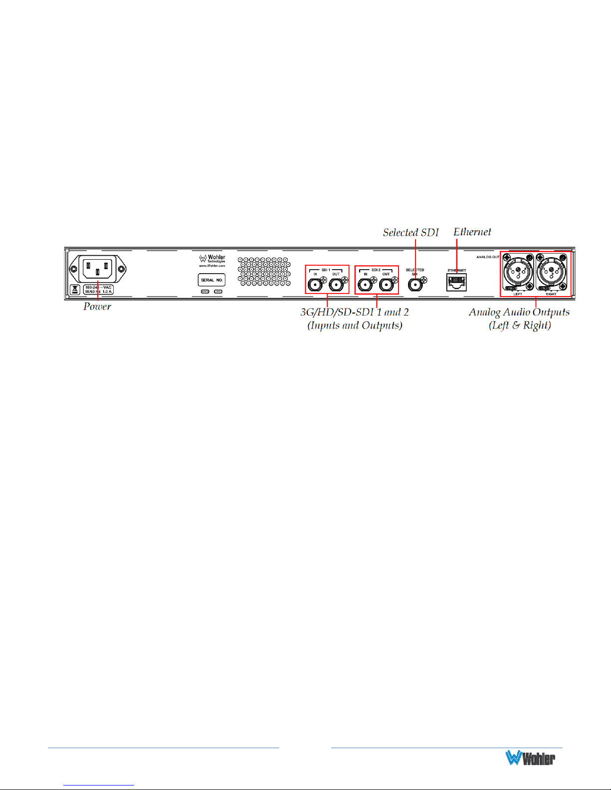
Rear Panel
Figure 1–2: Rear Panel Layout
1. Power: The AMP1-8-M uses a standard IEC power cord for the 100 to 240 VAC
±10%, 50/60 Hz power connection.
2. 3G/HD/SD-SDI Inputs: These two BNC connectors accept the 3G/HD/SD-SDI
input signals.
3. 3G/HD/SD-SDI Outputs: These BNC connectors output regenerated replicas
of the two 3G/HD/SD-SDI input signals.
4. Selected 3G/HD/SD-SDI Re-Clocked Output: This BNC connector re-clocks
the selected 3G/HD/SD-SDI input signal.
5. Ethernet: The AMP1-8-M does not currently use the Ethernet port except during
factory programming. For normal operation, the port may be connected to a LAN
or disconnected. In future releases, Wohler may or may not release remote
control software for this unit, such as is used in the AMP1-16-M.
6. Analog Outputs: These XLR connectors provide two channels of balanced
analog outputs. The source of these signals is the mix of audio monitored by the
internal speakers.
Page9
CHAPTER 2: Operation
Introduction
This chapter describes how to operate the AMP1-8-M.
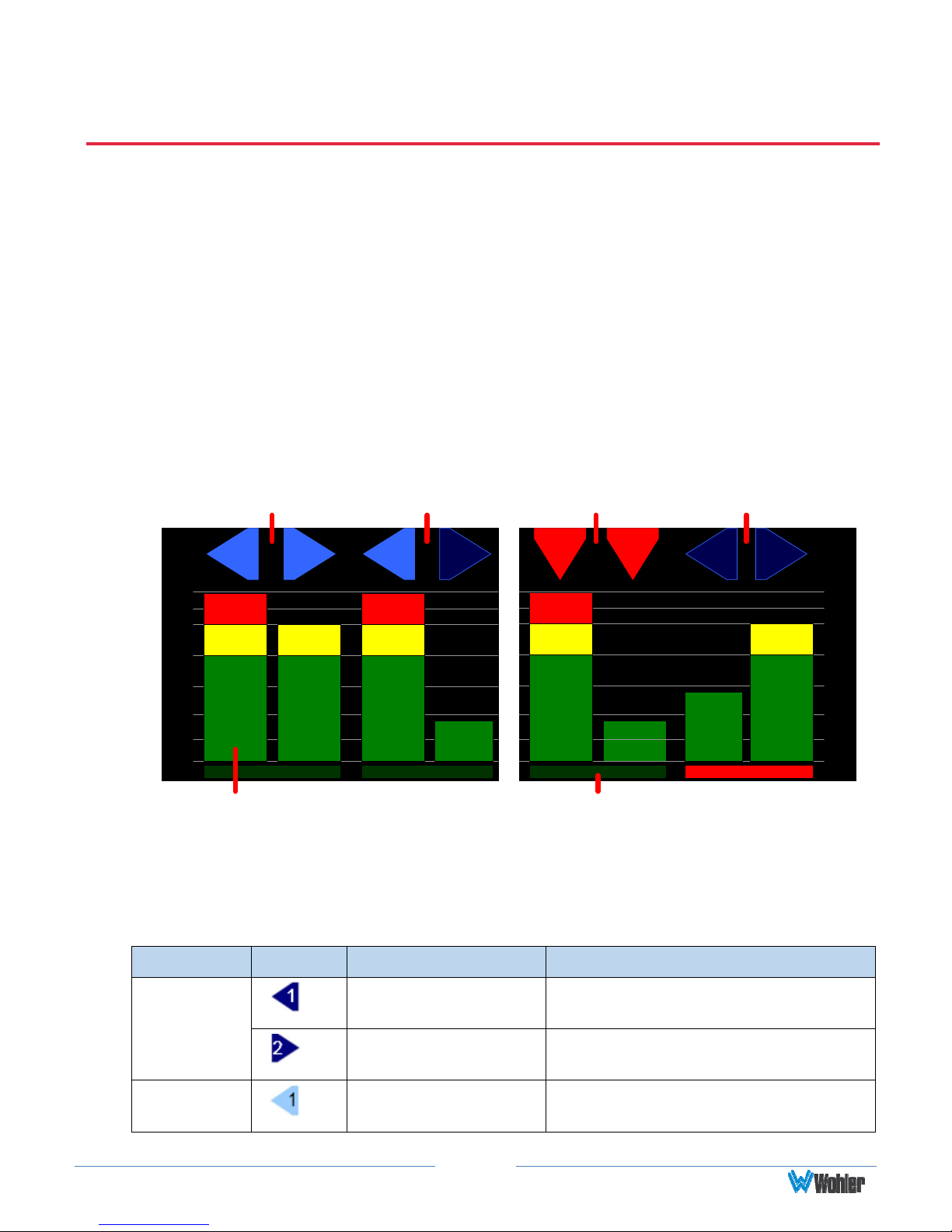
Main Screen
After powering up the AMP1-8-M and connecting an SDI input, you should see the
Main Screen, which will be similar to the one shown in Figure 2–1 below.
Fig 2–1: Main Screen
Speaker Indicators
(Left and Right)
1 2
0
0
-10
-10
-20
-20
-30
-30
-40
-40
-50
-50
-60
-60
Level Meters Phase Indicators
Speaker Indicators
(Left Selected, Right Muted)
3 4 7 8
Speaker Indicators
(Bitstream)
5
6
Speaker Indicators – No
Audio (Left and Right)
1. Speaker Indicators: The indicators above each meter identify the channel
number and the status of the channel.
Table 2-1: Channel Icon Descriptions
0
-10
-20
-30
-40
-50
-60
Attribute Symbol Description Meaning
Icon
Shape
Icon Color
Left Pointing Blue
Triangle
Right Pointing Blue
Triangle
Light Blue Triangle
or Square
Page10
Channel Configured to sounds in
the left speaker
Channel configured to sound in the
right speaker
Channel is selected by the Channel
Select buttons and can be heard
 Loading...