

Wohler AMP1-2SDA User Manual

AMP1-2SDA
1RU, 2-Channel, 3G/HD/SD-SDI / AES / Analog
Audio Monitor
User Guide
Software Release: V1.xx
Part Number 821817, Revision A

© 2016 Wohler Technologies, Inc. All rights reserved.
This publication is protected by federal copyright law. No part of this publication may be copied or
distributed, stored in a retrieval system, or translated into any human or computer language in any
form or by any means electronic, mechanical, manual, magnetic, or otherwise, or disclosed to third
parties without the express written permission of Wohler Technologies, Inc.
Reproduction
Licensed users and authorized distributors of Wohler Technologies, Inc. products may copy this
document for use with Wohler Technologies., Inc. products provided that the copyright notice above
is included in all reproductions.
Customer Support
Wohler Technologies, Inc.
31055 Huntwood Avenue
Hayward, CA 94544 www.wohler.com
Phone: 510-870-0810
FAX: 510-870-0811
US Toll Free: 1-888-596-4537 (1-888-5-WOHLER)
Web: www.wohler.com Sales: sales@wohler.com
Support: support@wohler.com
Disclaimers
Even though Wohler Technologies, Inc. has tested its equipment and software, and reviewed the
documentation, Wohler Technologies, Inc. makes no warranty or representation, either express or
implied, with respect to software, documentation, their quality, performance, merchantability, or
fitness for a particular purpose.
In no event will Wohler Technologies, Inc. be liable for direct, indirect, special, incidental, or
consequential damages resulting from any defect in the hardware, software, or its documentation,
even if advised of the possibility of such damages.
Some states do not allow the exclusion or limitation for incidental or consequential damages, so the
above exclusion or limitation may not apply to you.
Printing
This document looks best when printed on a color printer since some images may be indistinct when
printed on a black and white printer.
PDF
All text strings appearing in this shade of blue are hyperlinks.
Other Technologies and Products
Google Chrome is a registered trademark of Alphabet Inc. Microsoft Windows and Internet Explorer
are registered trademarks of Microsoft Corporation.
Last Update
September 7, 2016
Page2

TABLE OF CONTENTS
Contents
User Guide ........................................................................................ 1
TABLE OF CONTENTS .......................................................................... 3
Contents ....................................................................................................... 3
CHAPTER 1: Quick Start ....................................................................... 5
Introduction .................................................................................................. 5
Overview ............................................................................................ 5
Safety .......................................................................................................... 5
Instructions ......................................................................................... 5
Safety Symbols .................................................................................... 6
Mounting ............................................................................................. 6
Heat Dissipation ................................................................................... 6
Sympathetic Vibration ........................................................................... 7
Mechanical Bracing ............................................................................... 7
Connections and Cable Recommendations ................................................ 7
Electrical Interference ........................................................................... 7
Power ................................................................................................. 7
Compliance ................................................................................................... 8
FCC .................................................................................................... 8
ICES-003 ............................................................................................ 8
Front Panel .................................................................................................... 8
Rear Panel .................................................................................................... 9
CHAPTER 2: Operation ....................................................................... 13
Introduction ................................................................................................ 13
Main Screen ................................................................................................ 13
CHAPTER 3: Option Settings ............................................................... 15
Introduction ................................................................................................ 15
Option Menu Overview .................................................................................. 15
Option Settings ............................................................................................ 16
CHAPTER 4: Features & Specifications .................................................. 18
Introduction ................................................................................................ 18
Features ..................................................................................................... 18
Compliance ................................................................................................. 19
Specifications .............................................................................................. 19
SDI Audio Formats ....................................................................................... 20
Technical Functional Overview ........................................................................ 21
APPENDIX A: Firmware Updates .......................................................... 22
Page3

Introduction ................................................................................................ 22
Upgrading the Firmware Using a USB Flash Drive .............................................. 22
Possible Firmware Update Problems ................................................................ 23
Page4

CHAPTER 1: Quick Start
Introduction
Overview
The AMP1-2SDA is a 1RU, 2-channel, 3G/HD/SD-SDI, AES, and Analog audio
monitor. This unit comes with a powerful audio amplifier to overcome ambient
noise. It also has two 26-segment level meters for audio level metering. You can
visually and audibly monitor any selected audio pair. There is also a 4-digit, 14segment display for setup and status display. The AMP1-2SDA is small, low-cost,
reliable and simple to operate.
Note that very little configuration should be necessary. We have already configured
the unit to the most commonly requested settings. However, should you need to
change these settings, you can quickly and easily access the optional settings using
the front panel controls and the Status Display.
Safety
Instructions
1. Read, keep, and follow all of these instructions; heed all warnings.
2. Do not use this equipment near water.
3. Use only a dry cloth to clean the equipment.
4. Do not block any ventilation openings.
5. Do not install near any heat source such as a radiator, heat register, amplifier, or
stove.
6. Do not attempt to plug the unit into a two-blade outlet (with only two prongs of
equal width).
Important:
7. Protect the power cord from being walked on or pinched, particularly at plug
connections on the equipment and at the socket.
By design, this monitor will only plug into a three-prong outlet for
your safety. If the plug does not fit into the outlet, contact an
electrician to replace the obsolete outlet.
8. Use only the attachments/accessories specified by the manufacturer.
9. Unplug the equipment during lightning storms or when unused for long periods
of time.
10. Refer all servicing to qualified service personnel. Servicing will be required
Page5
3”
2”
under all of the following conditions:
a. The equipment has been damaged in any way, such as when the power-
supply cord or plug is damaged.
b. Liquid had been spilled or objects have fallen onto the equipment.
c. The equipment has been exposed to rain or moisture.
d. The equipment does not operate normally.
e. The equipment has been dropped.
Safety Symbols
The symbol to the left warns of electric shock hazard inside the unit.
Disconnect the power cord before removing access panels when installing
upgrades. Only qualified service personnel are to operate the equipment
with covers removed, and are to exercise caution to avoid personal injury.
Mounting
The unit is designed for a standard 19" rack. Install it at ear/eye level for best high
frequency response and visual observation of the display screens. Please adhere to
the following clearances:
Table 1-1: Clearance Recommendations
Clearance
Surface
24” Front
Rear
Sides
1.75” Top and Bottom (if either radiates heat)
0” Top and Bottom (if no heat)
Heat Dissipation
The ambient temperature inside the mounting enclosure should not exceed 40°
Celsius (104° Fahrenheit). Adjacent devices can be rack mounted (or stacked) in
proximity to the unit if this temperature is not exceeded. Otherwise, allow a 1RU
(1.75”/44.45mm) space above and below the unit for air circulation.
Important:
To reduce noise, the monitor does not have any fans. As a result, the
heat generated by the class D power amplifiers, power supplies, and
other components is vented by slots in the sides and back of the unit.
Therefore, as a safety precaution, you must allow proper ventilation
on these surfaces.
Page6
Sympathetic Vibration
Sympathetic vibration from other equipment (cables, etc.,) in the rack may be
serious enough to interfere with the sound quality of the unit. If you experience
sympathetic vibrations, use thin card stock, felt, foam, or weather-stripping
between the vibrating surfaces. Tie loose cables securely with cable ties.
Mechanical Bracing
The 1RU chassis is securely attached to the front panel. In addition, the chassis has
mounting tabs through which you attach it to the rack rail. This feature will reduce
or eliminate rear bracing requirements in many mobile/portable applications. The
weight of internal components is distributed fairly evenly around the unit.
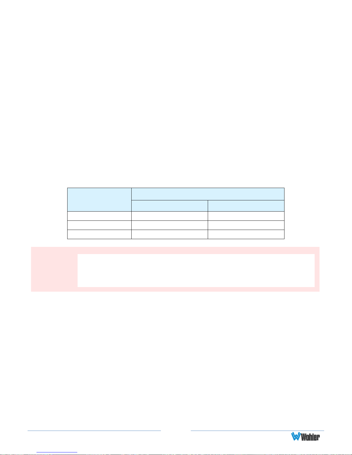
Connections and Cable Recommendations
We recommend that you limit the length of the cables that you use for feeding
3G/HD/SD-SDI signals sources to the SDI connector and that you use a Belden
1694A cable (or equivalent).
Table 1-2: SDI Cable Length Limit Recommendations
Note:
Signal Type
Maximum Length
Meters Feet
SD 300 984
HD 150 492
3G 75 246
The connections of all DB-25 connectors are compatible with
Tascam DB-25 to XLR cable assemblies. Consult the factory
for availability. All rear panel connectors are female except
for the XLR output connectors.
Electrical Interference
Be careful to avoid mismatched cable types and other similar causes of undesired
reflections in digital signal systems. If severe enough, such reflections can result in
corruption of the digital data stream. As with any audio equipment, maximum
immunity from electrical interference requires the use of shielded cable; however,
satisfactory results can sometimes be obtained without it. The internal circuitry
ground is connected to the chassis.
Power
The unit comes with a standard internal power supply and connects an A/C mains
power source (60W, 100 to 240 VAC, ±10%, 50/60Hz) through the IEC connector
provided on the rear panel of the unit.
Page7
 Loading...