

Wohler AMP1-16-3G, AMP1-E16-3G User Manual

AMP1-16 Series
• AMP1-16-3G • AMP1-E16-3G
1RU, 3Gb/s, 16-Channel, Audio and
Video Monitor
User Guide
(Software Version: 3.00)
Part Number 821697, Revision H

© 2011 Wohler Technologies, Inc. and PANORAMA. All rights reserved.
This publication is protected by federal copyright law. No part of this publication may be
copied or distributed, stored in a retrieval system, or translated into any human or computer
language in any form or by any means electronic, mechanical, manual, magnetic, or otherwise,
or disclosed to third parties without the express written permission of Wohler Technologies.
Reproduction
Licensed users and authorized distributors of Wohler Technologies, Inc. products may copy
this document for use with Wohler Technologies., Inc. products provided that the copyright
notice above is included in all reproductions.
Customer Support
Wohler Technologies, Inc.
31055 Huntwood Avenue
Hayward, CA 94544
www.wohler.com
Phone: 510-870-0810
FAX: 510-870-0811
US Toll Free: 1-888-596-4537
(1-888-5-WOHLER)
Web: www.wohler.com
Sales: sales@wohler.com
Support: support@wohler.com
Disclaimers
Even though Wohler Technologies, Inc. has tested its equipment and software, and reviewed
the documentation, Wohler Technologies, Inc makes no warranty or representation, either
express or implied, with respect to software, documentation, their quality, performance,
merchantability, or fitness for a particular purpose.
In no event will Wohler Technologies, Inc. be liable for direct, indirect, special, incidental, or
consequential damages resulting from any defect in the hardware, software, or its
documentation, even if advised of the possibility of such damages.
Some states do not allow the exclusion or limitation for incidental or consequential damages, so
the above exclusion or limitation may not apply to you.
Printing
This document is intended to be printed on a duplex printer, such that the copy appears on
both sides of each page. This ensures that all new chapters start on a right-facing page.
This document looks best when printed on a color printer since some images may be indistinct
when printed on a black and white printer.
PDF
All text strings appearing in this shade of blue are hyperlinks.
Other Technologies and Products
Dolby is a registered trademark of Dolby Laboratories, Inc.
Microsoft Windows, and Internet Explorer are registered trademarks of Microsoft Corporation.
Last Update
August 26, 2011
821697: AMP1-16 Series User Guide
ii
© 2011 Wohler Technologies, Inc. All rights reserved.

Table of Contents
Chapter 1. Quick Start. . . . . . . . . . . . . . . . . . . . . . . . . . . . .1
Introduction ...................................................................1
Overview..................................................................1
Topics......................................................................1
Safety Instructions ...................................................2
Installation Recommendations...........................................3
Mounting..................................................................3
Heat Dissipation........................................................3
Power ......................................................................3
FCC Compliance..............................................................3
Using the Monitor............................................................4
Front Panel...............................................................4
Back Panel................................................................5
Getting Started...............................................................6
Configuring the System....................................................8
Chapter 2. Audio and Metering . . . . . . . . . . . . . . . . . . . . . .9
Introduction ...................................................................9
Overview..................................................................9
Topics......................................................................9
Configuration Options ....................................................10
Configuring the Audio Outputs ........................................10
Overview................................................................10
Surround Sound......................................................11
Stereo Downmix......................................................12
AES and Analog Outputs...........................................15
Level Metering..............................................................18
Overview................................................................18
Metering Menus.......................................................19
821697: AMP1-16 Series User Guide
© 2011 Wohler Technologies, Inc. All rights reserved.
iii

Chapter 3. Video and Data . . . . . . . . . . . . . . . . . . . . . . . . 21
Introduction..................................................................21
Overview................................................................21
Topics ....................................................................21
Configuration Options ....................................................22
Overview................................................................22
Video Menus ...........................................................23
Chapter 4. Efficiency Enhancements . . . . . . . . . . . . . . . . 25
Introduction..................................................................25
Overview................................................................25
Topics ....................................................................25
Presets ........................................................................26
Overview................................................................26
Saving Presets...................................................26
Recalling Presets................................................26
Naming or Renaming................................................27
Clearing a Preset .....................................................28
Recalling a Preset On Power Up .................................29
Hot Keys ......................................................................29
Overview................................................................29
Mutes and Solos ......................................................29
Defining/Modifying a Hot Key ....................................30
Creating a Preset Hot Key.........................................31
Naming/Renaming a Hot Key.....................................31
Copying Presets to Another Monitor .................................32
Preset Files.............................................................32
Verif ying Compatibili ty..............................................33
Backing Up the Saved Presets ...................................35
Copying the Presets to Another Monitor ......................35
General Purpose Inputs and Outputs (GPI/Os)...................36
Turning Active Help On or Off..........................................37
821697: AMP1-16 Series User Guide
iv
© 2011 Wohler Technologies, Inc. All rights reserved.

Chapter 5. Menu List . . . . . . . . . . . . . . . . . . . . . . . . . . . . .39
Introduction .................................................................39
Overview................................................................39
Topics....................................................................39
Menu Navigation Overview .............................................40
AES Output Configuration Menu ......................................42
Analog Output Configuration Menu...................................44
Configuration Selection Menu..........................................46
Cluster Configuration Menu.............................................47
Dolby Setup Menu.........................................................48
Hardware Configuration Menu.........................................49
Label Menu Screen ........................................................51
Loudness Configuration Menu Screen...............................52
Main Screen .................................................................53
Main Screen Hot Key Button Configuration Menu ...............55
Meter Configuration Menu...............................................56
Monitor Mixer Configuration Menu....................................58
Option Configuration Menu .............................................60
Preset Management Menu ..............................................61
Screen Display Menu .....................................................62
Screen Information Setup Menu ......................................63
Unit Information Menu...................................................65
Chapter 6. System Maintenance . . . . . . . . . . . . . . . . . . . .67
Introduction .................................................................67
Overview................................................................67
Topics....................................................................67
Upgrade Requirements............................................68
Establishing Connectivity................................................69
Upgrading the Netburner Software...................................69
Upgrading the Sub-Processor Firmware............................71
821697: AMP1-16 Series User Guide
© 2011 Wohler Technologies, Inc. All rights reserved.
v

Chapter 7. Features and Specifications . . . . . . . . . . . . . . 77
Introduction..................................................................77
Overview................................................................77
Topics ....................................................................77
Features ............................................................... 78
Product Benefits ......................................................78
Distinction Between Models.......................................79
Additional Features ..................................................79
Compliance.............................................................80
Standards...............................................................80
Specifications................................................................80
Technical Functional Overview.........................................83
Appendix A. Downloading Software. . . . . . . . . . . . . . . . . 85
Introduction..................................................................85
Overview................................................................85
Topics ....................................................................85
Requirements........................................................ 86
Downloading the File......................................................86
Appendix B. Establishing Connectivity . . . . . . . . . . . . . . . 89
Introduction..................................................................89
Overview................................................................89
Topics ....................................................................89
Connectivity Options .............................................. 90
Connecting to a LAN ......................................................90
Launching the Setup Tool..........................................90
Setting the IP Address and Network Mask ...................91
Connecting Directly........................................................92
821697: AMP1-16 Series User Guide
vi
© 2011 Wohler Technologies, Inc. All rights reserved.

Appendix C. Setting Up File Transfers. . . . . . . . . . . . . . . .97
Introduction .................................................................97
Overview................................................................97
Topics....................................................................97
Navigating to the Unit Information Menu ................... 98
Enabling FTP Access ......................................................99
821697: AMP1-16 Series User Guide
© 2011 Wohler Technologies, Inc. All rights reserved.
vii


Introduction
Overview
The AMP1-16-3G and AMP1-E16-3G are Wohler’s first 1RU,
16-channel, 3G audio/video monitors. These units come with three 2.4”
video screens and an easy-to-use configuration interface that provides
flexible audio metering, video monitoring, and other data display.
CHAPTER 1
Quick Start
Topics
Topics Page
Quick Start 1
Safety Instructions 2
Installation Recommendations 3
FCC Compliance 3
Using the Monitor 4
Getting Started 6
Configuring the System 8
821697: AMP1-16 Series User Guide
© 2011 Wohler Technologies, Inc. All rights reserved.
1

Chapter 1 Quick Start
Safety Instructions
Safety Instructions
1. Read, keep, and follow all of these instructions; heed all warnings.
2. Do not use this equipment near water.
3. Use only a dry cloth to clean the equipment.
4. Do not block any ventilation openings. Install only in accordance
with the instructions in the section entitled, “Installation
Recommendations” on page 3.
5. Do not install near any heat source such as a radiator, heat register,
amplifier, or stove.
6. Do not expose the equipment to rain or moisture.
7. Do not attempt to plug the unit into a two-blade outlet (with only
two prongs of equal width).
IMPORTANT:
By design, this monitor will only plug into a three-prong outlet for
your safety. If the plug does not fit into your outlet, contact an
electrician to replace the obsolete outlet.
8. Protect the power cord from being walked on or pinched,
particularly at plug’s source on the equipment and at the socket.
9. Use only the attachments/accessories specified by the
manufacturer.
10. Unplug the equipment during lightning storms or when unused
for long periods of time.
11. Refer all servicing to qualified service personnel. Servicing will be
required under all of the following conditions:
• The equipment has been damaged in any way, such as when
the power-supply cord or plug is damaged.
• Liquid had been spilled or objects have fallen onto the
equipment.
• The equipment has been exposed to rain or moisture.
• The equipment does not operate normally.
• The equipment has been dropped.
821697: AMP1-16 Series User Guide
2
© 2011 Wohler Technologies, Inc. All rights reserved.

Chapter 1 Quick Start
Installation Recommendations
Installation Recommendations
Mounting
The unit is designed to install into a standard 19" rack, mounted at eye
level for best visual observation of the monitor screens. After installing
the AMP1-16-3G, remove the clear, plastic protective covers from each
screen using the tabs provided.
Heat Dissipation
The ambient temperature inside the mounting enclosure should not
exceed 40° Celsius (104° Fahrenheit). Adjacent devices can be rack
mounted (or stacked) in proximity to the unit if the above temperature
is not exceeded. If the product must be operated in an environment
with an elevated temperature, allow a 1RU (1.75”/44.45mm) space
above and below the unit for air circulation.
Important:
To reduce noise, neither the AMP1-16-3G nor the AMP1-E16-3G have
any fans. As a result, the heat generated by the class D power
amplifiers, power supplies, and other components is vented by slots in
the sides of the unit. Therefore, as a safety precaution, we advise you to
be sure to allow proper ventilation on both sides of the unit.
Power
The AMP1-16-3G has a standard IEC connector on the rear panel from
which it can connect to AC mains power (100 to 240 VAC ± 10%, 50/60
Hz, 65W). You may use the power cord provided, or another approved
cord, to adapt the unit to the proper country-specific power connection.
FCC Compliance
This equipment has been tested and found to comply with the limits for
a Class A digital device, pursuant to part 15 of the FCC Rules. These
limits are designed to provide reasonable protection against harmful
interference when the equipment is operated in a commercial
821697: AMP1-16 Series User Guide
© 2011 Wohler Technologies, Inc. All rights reserved.
3
Chapter 1 Quick Start
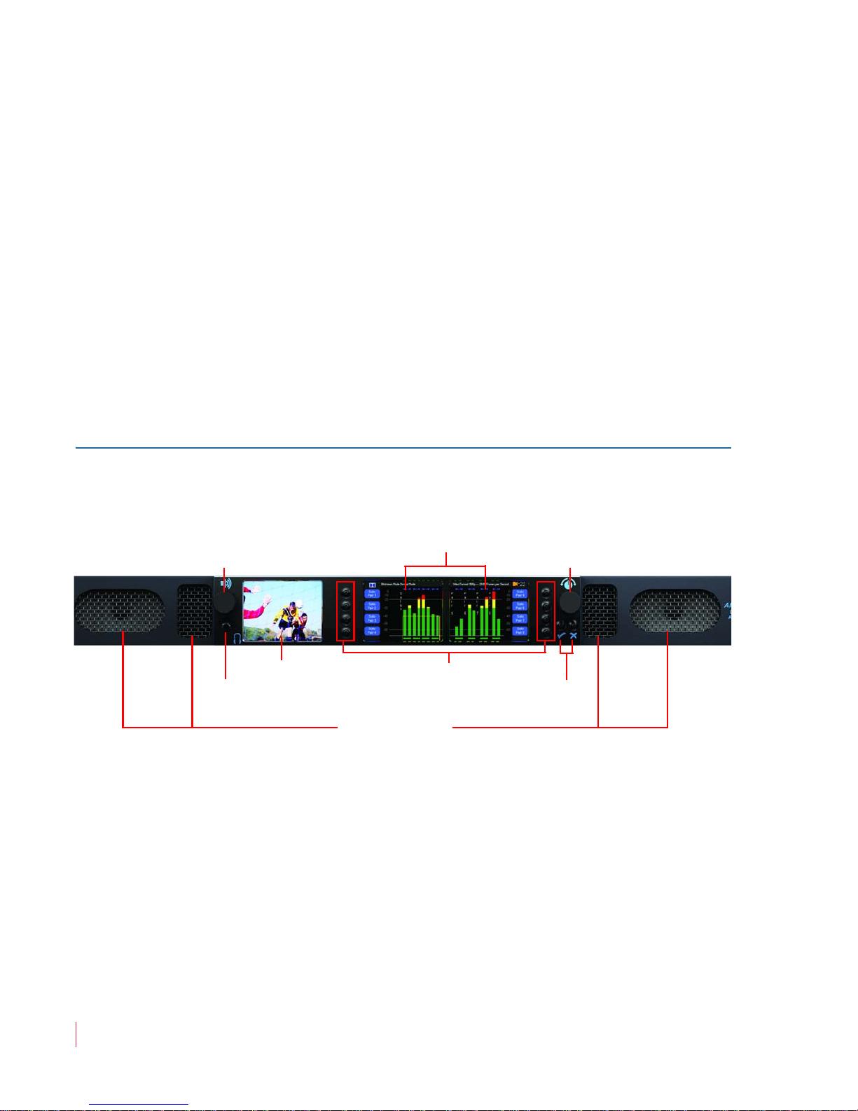
Speakers
Headphone Jack
Volume
(Rotary Knob)
Balance and Menu
Navigation
(Rotary Knob)
Video Monitor
Hot Keys/Menu Buttons
Data/Menu
Monitors
Menu Navigation Buttons
Using the Monitor
environment. This equipment generates, uses, and can radiate radio
frequency energy and, if not installed and used in accordance with the
instruction manual, may cause harmful interference to radio
communications. Operation of this equipment in a residential area is
likely to cause harmful interference in which case the user will be
required to correct the interference at his own expense.
Using the Monitor
This section provides a brief overview of the controls on the front
panel, and the connectors on the back panel of the monitor.
Front Panel
Figure 1–1 Front Panel Layout
Speakers: Audio monitoring is achieved through the use of class D
amplifiers driving two (left/right) wide range speakers.
Headphone Jack: A class B amplifier drives the front panel 3.5 mm
jack for an optional headphone.
Balance and Volume Rotary Knobs: Control knobs are on the left and
right of the front panel video displays. The left knob controls the
Volume and the speaker output and can be programmed to control the
AES and Analog outputs. Pressing this control drops the internal
speaker volume by 20 dB. Pressing it a second time mutes the internal
821697: AMP1-16 Series User Guide
4
© 2011 Wohler Technologies, Inc. All rights reserved.
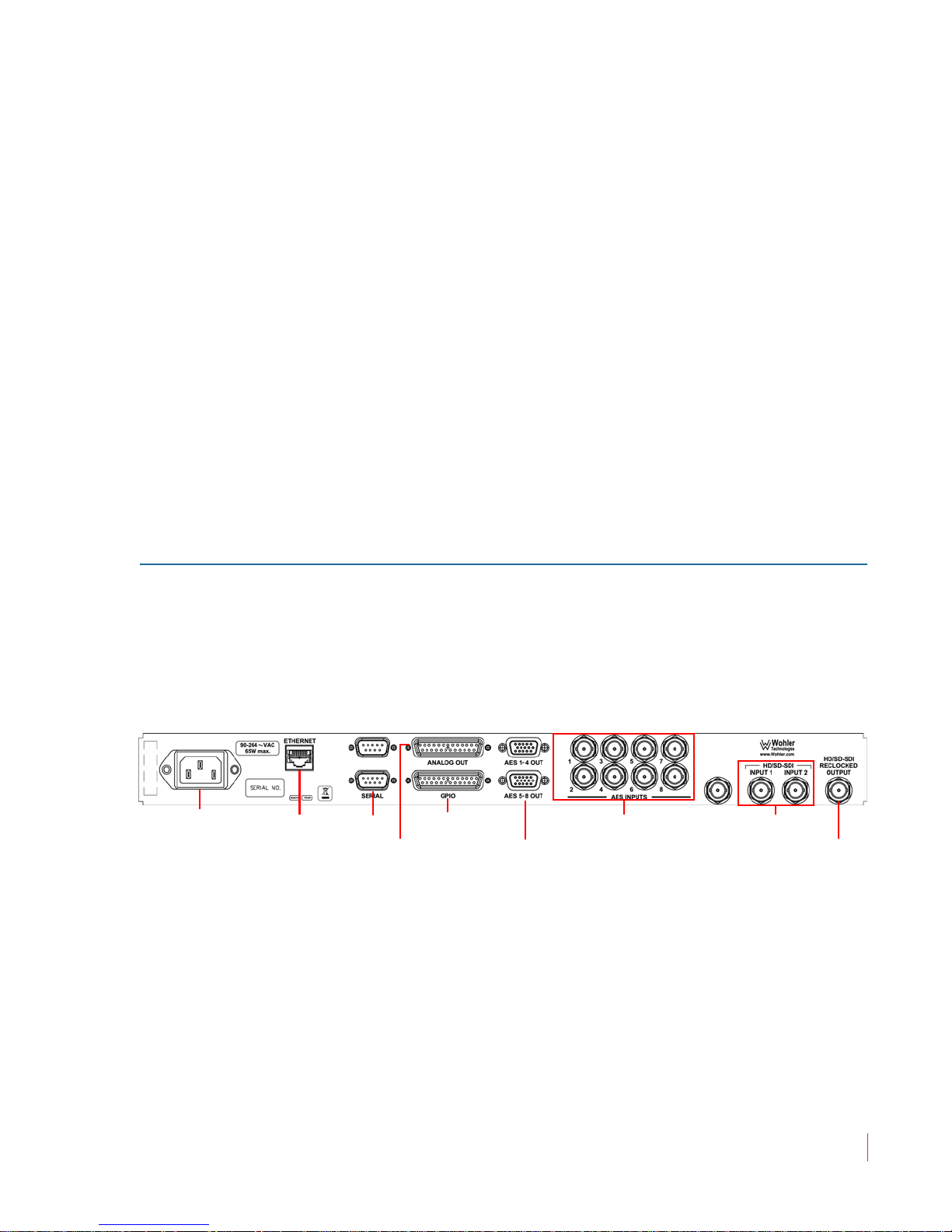
Chapter 1 Quick Start
Power Ethernet Serial GPI/O
AES Outputs
(1 - 4 and 5 - 8)
AES Inputs HD/SD-SDI Inputs
3G/HD/SD-SDI
Re-Clocked Output
Analog Output
Using the Monitor
speakers entirely. Pressing it a third time brings the internal speaker
volume back to normal. Turning the knob to increase the volume
increases it from the current volume, whether from the 20dB dip or
from the completely muted state.
Back Panel
The right knob adjusts the
Balance between the speakers. Pressing the
knob returns the audio balance to center. This knob is also used for
setting adjustments when programming the options and features in the
configuration menus.
Video Screen: This monitor (left) displays either video and/or data
such as help for the
Menu and Data Screens.
Menu and Data Screens: These two screens on the right work together
to display bar graphs and the configuration menus.
Hot Keys/Push Buttons: Ten buttons are used for menu navigation
and hot key access to solo, mute, and preset functions.
The AMP1-16-3G and AMP1-E16-3G back panel contains all of the
connectors except for the headphone jack as shown in Figure 1–2
below.
Figure 1–2 Back Panel Layout
• Power: The AMP1-16-3G and AMP1-E16-3G use a standard IEC
power cord for the 100 to 240 VAC power connection.
• Ethernet: The Ethernet port is used for system software upgrades.
• Serial: This DB-9F connector is used for system software upgrades.
• Analog Outputs: This DB-25F connector provides eight channels of
balanced analog outputs.The source of these signals is controlled by
821697: AMP1-16 Series User Guide
© 2011 Wohler Technologies, Inc. All rights reserved.
5

Chapter 1 Quick Start
Getting Started
the setup menus. (The pin out of this connector is shown in Table 2–
3 on page 17.)
• AES Outputs: Each of these two HD-15F connectors supplies four
pairs of unbalanced AES outputs for a total of eight. The source of
these signals is determined by the setup menus. (The pin out of
these connectors is shown in Table 2–2 on page 16.)
• AES Inputs: Each of these eight BNC connectors provides an
unbalanced AES input. The monitoring of these signals is
determined by the setup menus.
• 3G/HD/SD-SDI Inputs: These two BNC connectors input two
separate SDI signals. Front panel controls select between the two for
monitoring or down converting.
• 3G/HD/SD-SDI Re-Clocked Output: This BNC connector outputs
a re-clocked replica of the selected 3G/HD/SD-SDI input signal.
Getting Started
Once you have connected a 3G/HD/SD SDI video signal to one of the
video inputs on the back of the unit, it should display on the video
monitor after a few seconds.
Figure 1–3 Video Monitor Display (Left)
To begin any procedure on the AMP1-16-3G or the AMP1-E16-3G,
powering up the system should display the video input on the left
821697: AMP1-16 Series User Guide
6
© 2011 Wohler Technologies, Inc. All rights reserved.
Chapter 1 Quick Start
Solo
Pair 5
Solo
Pair 6
Solo
Pair 7
0
-60
-10
-20
-30
-40
-50
P
a
i
r
5
P
a
i
r
6
P
a
i
r
7
P
a
i
r
8
Solo
Pair 8
-22
Solo
Pair 3
Solo
Pair 1
0
-60
-50
-40
-30
-10
-20
P
a
i
r
1
P
a
i
r
2
P
a
i
r
3
P
a
i
r
4
Solo
Pair 4
Solo
Pair 2
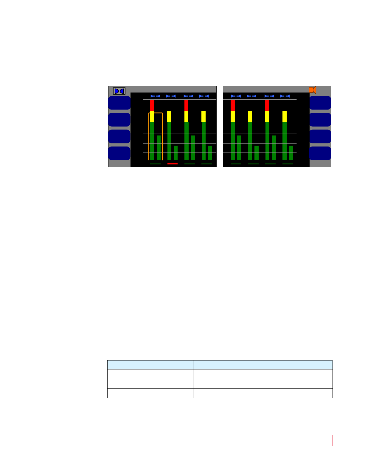
Getting Started
screen, and the audio level meters on the Main Screen as shown in
Figure 1–4 below.
Figure 1–4 Main Screen (Center and Right)
You can launch the menu system by pressing either of the buttons
directly below the Balance control. These same buttons also either
(Save and Exit) or (Cancel and Exit). Context-sensitive, active
help appears automatically on the left hand screen for any function.
From the Main Screen, press either the button or the button to
display the Configuration Selection Menu. The eight buttons
surrounding the screen allow you to access options or functions on the
screen or to proceed to other menus.
Note that the Balance knob is multifunctional. When the Main
Screen
menu is displayed, it is used to adjust settings. The actual audio balance
does not change while the
the product.
Generally, to make changes, press the button next to the item you want
to change. Then rotate the Balance knob to highlight the option that
you want and press the
Table 1–1 Typical Knob/Button Functionality
Press an option button Highlights the name of the option
Rotate the
Press the
is displayed, it controls the audio balance, but when any setup
Balance knob is being used for setting up
Balance knob to select it.
Action Result
Balance knob Scrolls through the available options
Balance knob Selects the highlighted option
© 2011 Wohler Technologies, Inc. All rights reserved.
821697: AMP1-16 Series User Guide
7
Chapter 1 Quick Start
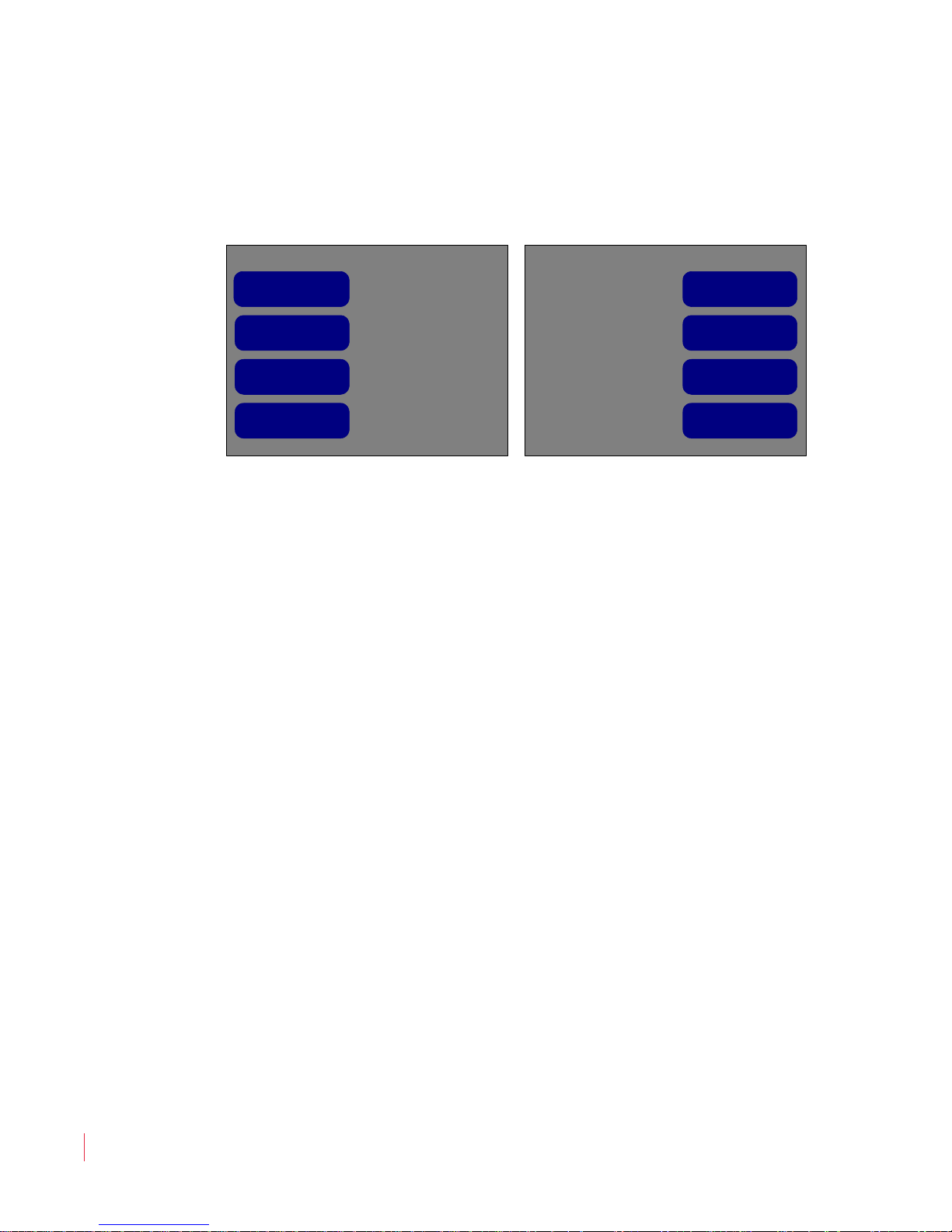
Configuration Selection Menu
Monitor Menu
Preset ManagementRecall a Preset
8
SDI Source
Screen Display
Menu
2
Analog Output
Menu
AES Output Menu
Late Show
Dolby Menu
Push to recall
Configuring the System
To move back up in the menu tree, press either the button (to save)
or the button (to cancel) repeatedly until you reach the
Screen
.
Figure 1–5 Configuration Selection Menu
Main
Configuring the System
The functional descriptions fall under the following categories:
• Configuring Audio and Metering (Chapter 2 on page 9)
• Configuring Video and Data (Chapter 3 on page 21)
• Configuring Presets and Hot Keys (Chapter 4 on page 25)
821697: AMP1-16 Series User Guide
8
© 2011 Wohler Technologies, Inc. All rights reserved.

Audio and Metering
Introduction
Overview
The AMP1-16 Series monitors are primarily designed to monitor audio
and video. Configuration options include specifying channels to
monitor, phase indicators, setting audio delay, and individual channel
volume controls.
CHAPTER 2
Topics
Topics Page
Introduction 9
Configuration Options 10
Configuring the Audio Outputs 10
Level Metering 18
821697: AMP1-16 Series User Guide
© 2011 Wohler Technologies, Inc. All rights reserved.
9

Chapter 2 Audio and Metering
Configuration Options
Configuration Options
The AMP1-16 Series monitors are very flexible and can be configured to
adapt to almost any audio configuration. The available adjustments are:
• Selecting the inputs (signal sources) to monitor
• Trimming the volume of each channel
• Indicating the phase relationship of each channel pair
• Muting the audio output of the speakers
• Selecting the signal sources for the AES and analog rear panel
outputs
• Selecting the Mo nitor Downmix
• Setting the audio delay for video synchronization
Configuring the Audio Outputs
Overview
You can route the digital audio signals at the inputs of the AMP1-16-3G
Series monitors to the front panel speakers or to the outputs, depending
on your needs. The internal routing paths are controlled by the settings
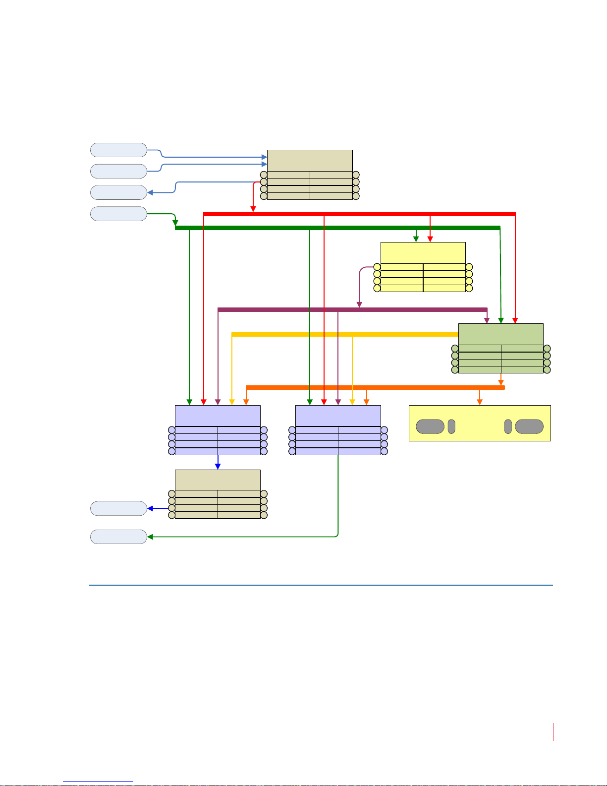
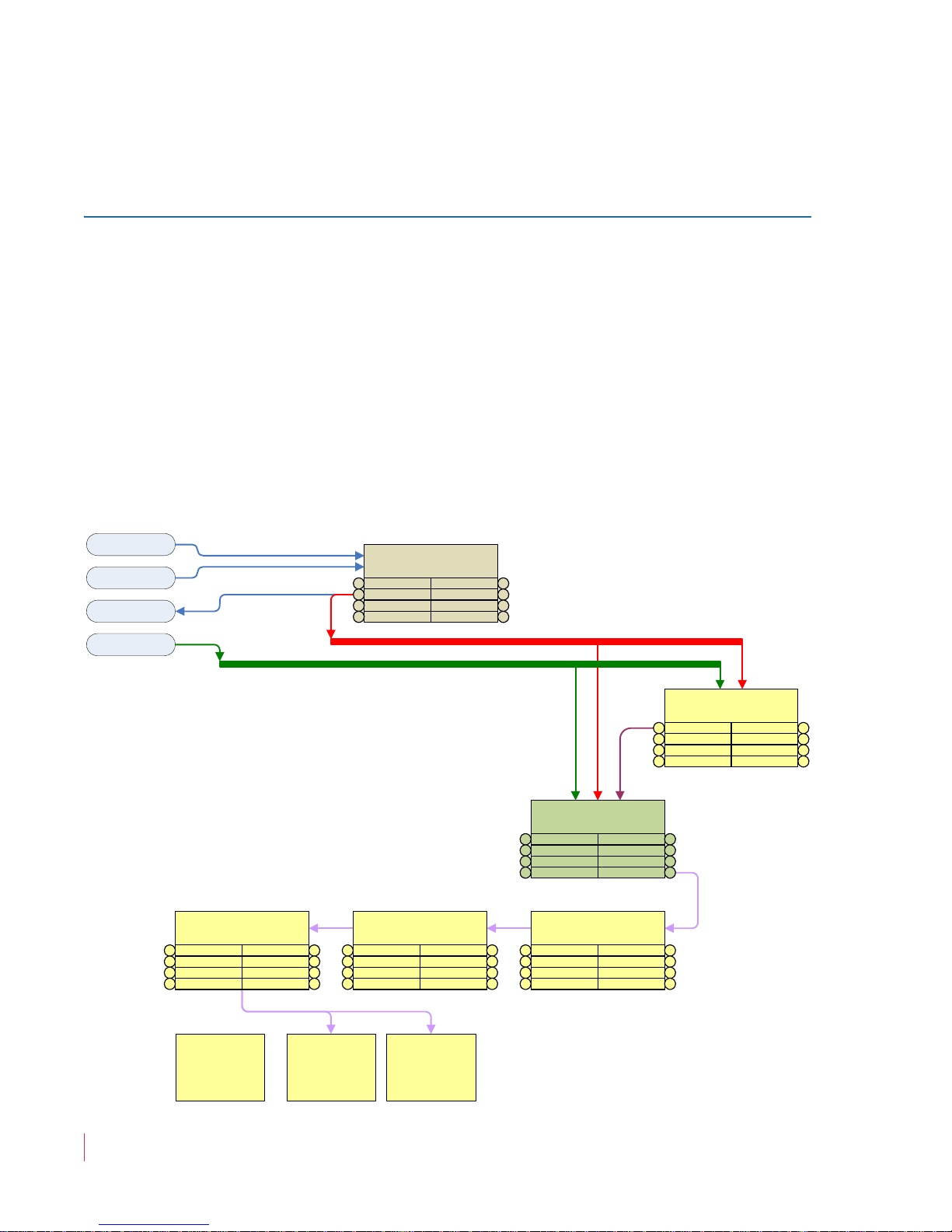
in the setup menus. The following diagram (Figure 2–1) shows the
relationship between the internal routing paths and the various menus
that control the signal flow.
The colors in this diagram represent various audio formats or levels of
processing. Each menu will select, route, or adjust the audio paths.
Further detail on each of these menus is available in Chapter 5: Menu
List on page 39.
Note that you can set up multiple audio paths. For example, while
monitoring de-embedded SDI audio channels through the speakers,
you may independently decode Dolby channels from an AES stream,
convert them to analog, and output them. Setups like this can be stored
821697: AMP1-16 Series User Guide
10
© 2011 Wohler Technologies, Inc. All rights reserved.
Chapter 2 Audio and Metering
3G SDI Input 1
3G SDI Input 2
3G SDI Output
AES Inputs
Analog Outputs
AES Outputs
Monitor Amplifiers, Speakers, & Headphone Jack
8 De-embedded SDI Pairs
8 AES Pairs
5 Dolby Pairs
8 Monitor Mixer Pa irs
Monitor Downmix Pair
Configuration Selection
Recall Preset1
SDI Source2
Monitor Menu3
Screen Menu4 Dolby
Preset Mgmt 5
Analog Out 6
7AES Out
8
Dolby Configuration Menu
Decoder Src1
Pro16 Mode2
Dolby E Pgm3
4
5
Bitstream Det 6
7
8
Monitor Mixer Config Menu
Sel Channel1
Channel Trim2
Spkr Assign3
Mute Spkrs4
Audio Delay 5
Channel Src 6
7
Phase LED 8
AES Output Menu
AES Output1
Affect S/M2
Level Trim3
AES Ch Pair4
5
6Affect Vol
7Chan Output
8Mute w/ HP
Analog Output Menu
Analog Out1
Affect S/M2
Level Trim3
Alg Ch Pair4
5
6Affect Vol
7Chan Output
8Mute w/ HP
Unit Info
Hardware Configuration
Menu
Screen Saver1
2
Analog Ref3
AES Term4
System Reset 5
Scrn Bright 6
7
AES Term All 8
Configuring the Audio Outputs
as presets and recalled later. See Chapter 4: Efficiency Enhancements on
page 25.
Figure 2–1 Audio Routing Diagram
Surround Sound
If a studio or other monitoring environment contains a surround sound
system, it may be advantageous to connect the monitored sound from
the AMP1-16 Series monitor to this system. Up to eight pairs (16
channels) of AES outputs or four pairs (eight channels) of analog
outputs are available for this use. The front panel Volume, Balance,
and solo, and mute controls will then optionally affect the surround
sound. You can easily configure this in the
Analog Output Configuration Menus as described below.
AES Output and the
821697: AMP1-16 Series User Guide
© 2011 Wohler Technologies, Inc. All rights reserved.
11

Chapter 2 Audio and Metering
AES Output Configuration Menu
AES Output Channels 5/6 AES Output Channels 7/8
+0 +0 +0 +0
Level Trim
Affected by
Volume Control
Affected by
Solos & Mutes
Output Mute
With Headphone
Channel Output
No
Yes
Yes
Yes
Yes
AES Output =
Monitor Channels
65 65 87 87
SDI In Channels 7/8SDI In Channels 3/4
AES Channel Pair
Configuring the Audio Outputs
1. From the Main Screen, press either the button or the
button to display the
Configuration Menu.
2. From the
Configuration Menu
Menu
example, we’re using the
3. If needed, press the
and then press the
Monitor Channels
Configuration Menu, select either the AES Output
or the Analog Output Configuration
depending on the output type you want to use. In our
AES Output Configuration Menu.
AES Output = Selected Sources button
Balance knob to display AES Output =
. This will set the outputs so that they match
those viewed on the meters in the Main Screen.
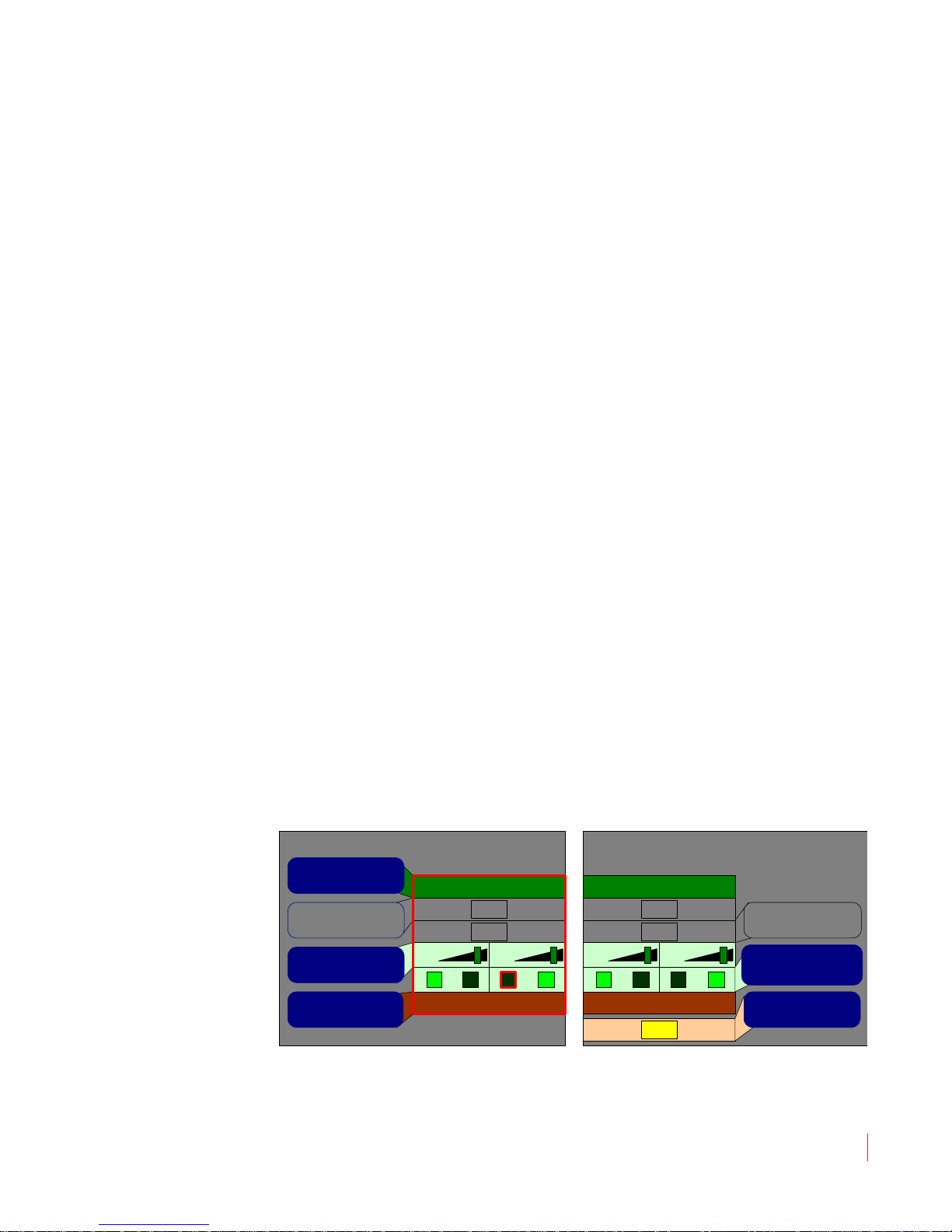
Figure 2–2 AES Output = Monitor Channels
4. You can also specify whether the outputs should be affected by:
A. The Solo and Mute hot keys (available per channel pair), by
pressing the
B. The front panel
by pressing the Affected by Volume Control button.
C. Inserting a pair of headphones to mute the output audio
channels (available system-wide), by pressing the Output
Mute with Headphone
Stereo Downmix
12
821697: AMP1-16 Series User Guide
© 2011 Wohler Technologies, Inc. All rights reserved.
If a studio or other monitoring environment contains a stereo sound
system, it may be advantageous to connect the monitored sound from
the AMP1-16 Series monitor to this system. One or more of the AES or
Affected by Solos and Mutes button.
Volume control (available per channel pair),
button.
Chapter 2 Audio and Metering
AES Output Configuration Menu
AES Output Channels 5/6 AES Output Channels 7/8
+0 +0 +0 +0
Level Trim
65 65 87 87
Affected by
Volume Control
Affected by
Solos & Mutes
Output Mute
With Headphone
AES Output =
Selected Sources
No
No
No
No
Yes
SDI In Channels 7/8SDI In Channels 5/6
Channel Output
AES Channel Pair
Configuring the Audio Outputs
analog output pairs are available for this purpose. The front panel
Volume, Balance, and solo controls will then affect the stereo
downmix output sound. You can easily configure a stereo downmix in
the AES Output Menu and the Analog Output Menu. Note that the
stereo downmix will also be affected by the trim, speaker assign, and
delay in the
trim, channel output, and mute with headphone settings in the
Output Menu
Monitor Mixer Configuration Menu, and also by the
AES
/Analog Output Menu.
The Monitor Downmix pair is one of the sources listed on the AES
Output Configuration Menu
Configuration Menu
. Configure either menu as follows.
and the Analog Output
1. From the Main Screen, press either the button or the
button to display the Configuration Menu.
2. From the Configuration Menu, select either the AES Output
Configuration Menu
Menu
depending on the output type you want to use. In our
or the Analog Output Configuration
example, we’re using the AES Output Configuration Menu.
3. If needed, press the AES Output = Monitor Channels button
and then press the Balance knob to display AES Output =
Selected Sources
See Figure 2–3 on page 13. In our example, the AES Output
Configuration Menu
Sources
“matching” inputs (5 and 6) and outputs (5 and 6). We’ll modify
this in the next step.
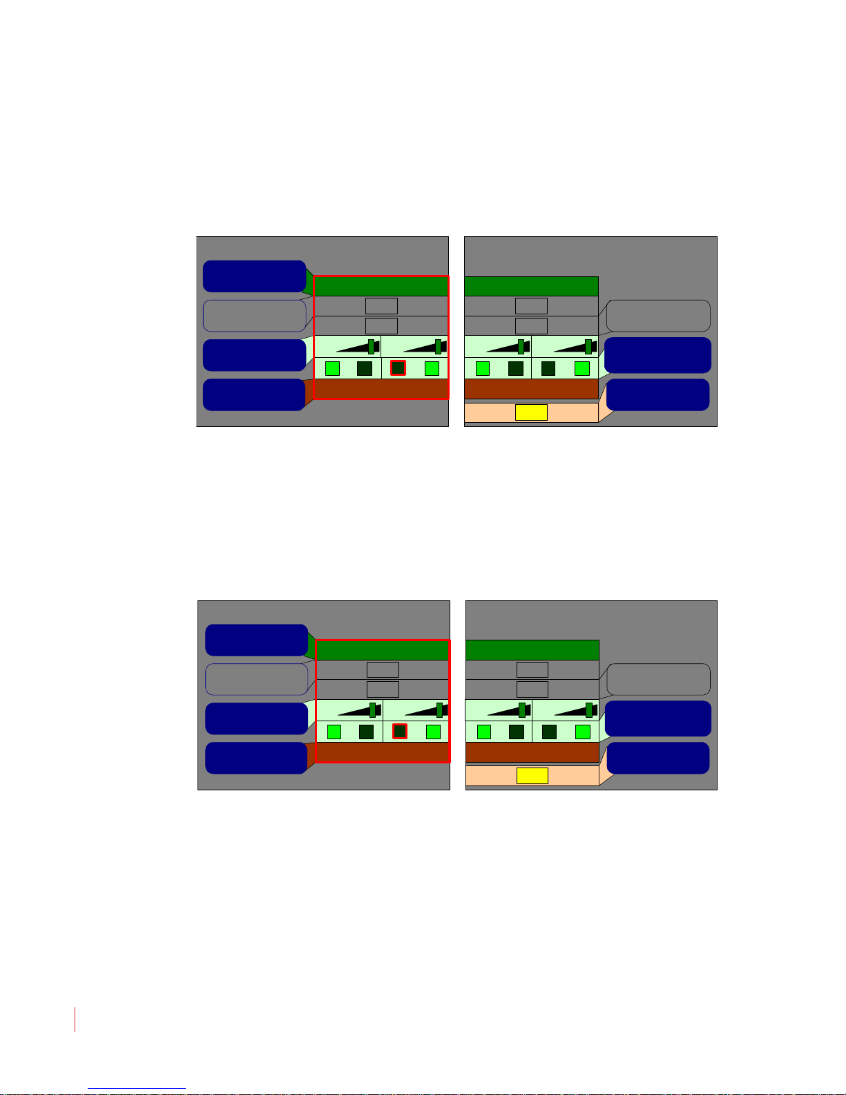
Figure 2–3 Select AES Output = Selected Sources
.
displayed with AES Output = Selected
so we didn’t need to change that. But it did display
© 2011 Wohler Technologies, Inc. All rights reserved.
821697: AMP1-16 Series User Guide
13
Chapter 2 Audio and Metering
AES Output Configuration Menu
AES Output Channels 1/2 AES Output Channels 3/4
+0 +0 +0 +0
Level Trim
21 21 43 43
Affected by
Volume Control
Affected by
Solos & Mutes
Output Mute
With Headphone
AES Output =
Selected Sources
No
No
No
No
Yes
SDI In Channels 7/8SDI In Channels 5/6
Channel Output
AES Channel Pair
AES Output Configuration Menu
AES Output Channels 1/2 AES Output Channels 3/4
+0 +0 +0 +0
Level Trim
21 21 43 43
Affected by
Volume Control
Affected by
Solos & Mutes
Output Mute
With Headphone
AES Output =
Selected Sources
No
No
No
No
Yes
SDI In Channels 3/4Monitor Downmix Pai r
Channel Output
AES Channel Pair
Configuring the Audio Outputs
4. Next, press the AES Channel Pair button and then rotate the
Balance knob to select the AES pair that will receive the Monitor
Downmix
. In our example in Figure 2–4 below, we selected
Channel Pair 1/2.
Figure 2–4 Select Outputs
5. When the outputs you want are highlighted, press the AES
Output = Source Select
Balance knob to select Monitor Downmix source. See Figure 2–
button again and then rotate the
5 on page 14 for the display.
Figure 2–5 Select Monitor Mix for the Input
6. You can repeat this procedure on other AES or analog outputs if
you need additional duplicate monitor mix outputs. Press the
button twice to return to the Main Screen.
14
821697: AMP1-16 Series User Guide
© 2011 Wohler Technologies, Inc. All rights reserved.

AES and Analog Outputs
Any monitored input can be routed to any AES or analog output pair.
This powerful feature will allow de-embedded, Dolby decoded, or
other digital or analog audio to be used by other products. The audio
that is output doesn’t necessarily need to be monitored by the meters or
speakers. You can easily configure this in the AES Output Menu and
the Analog Output Menu.
The AMP1-16 Series monitors contain both AES and analog outputs.
The sources of these outputs are set using the AES Output
Configuration Menu
The parameters that these menus adjust are as follows:
1. You can map either or both of these output ports pair-wise either
to the channel pairs that are metered and audibly monitored, or to
a selection of the SDI and AES inputs.
Chapter 2 Audio and Metering
Configuring the Audio Outputs
and Analog Output Configuration Menu.
2. If you map the output ports to the metered (and audibly
monitored) channel pairs, then you can also specify whether the
outputs should be affected by the:
A. Solo and Mute hot keys,
B. Front panel Volume control and Balance knobs, and/or
C. Insertion of a headphone in the front panel jack.
These settings are for typical use with an external surround sound
system.
3. If you map the output ports to selected sources, then you can use
them in a variety of useful roles, independent of monitoring and
metering. For example:
A. The SDI input pairs can be de-embedded into AES streams or
into analog audio.
B. The AES input pairs can be swapped pair-wise under control
of the AMP1-16 Series monitor to the AES outputs.
821697: AMP1-16 Series User Guide
© 2011 Wohler Technologies, Inc. All rights reserved.
15
Chapter 2 Audio and Metering
Configuring the Audio Outputs
C. The AES input pairs can be converted into analog audio.
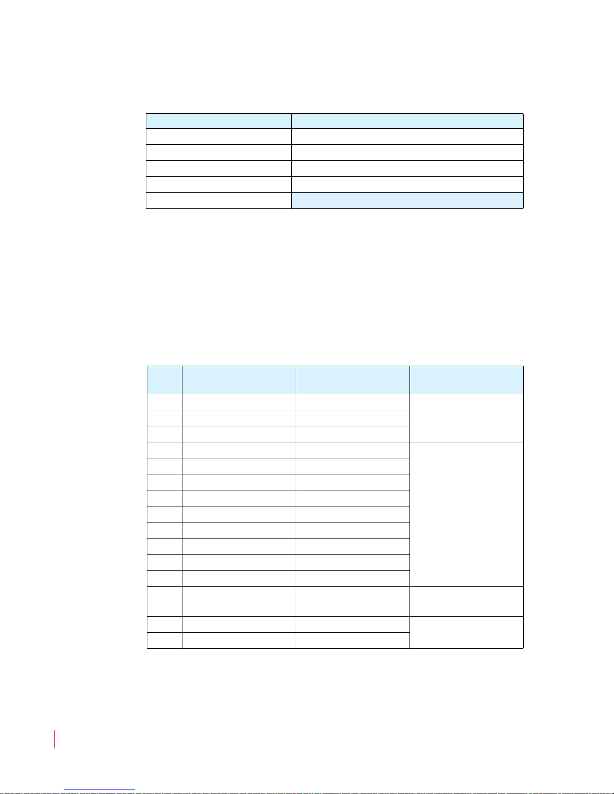
Table 2–1 Available Signal Types/Channels
Signal Sources Available Channel Pairs
SDI 1 through 8
AES 1 through 8
Dolby 1 through 5
Monitor Mix 1 through 8
Off
4. Each AES or analog output channel has its own individual volume
trim control with a range from -60 to +12 dB in 1 dB steps.
5. You can turn each channel on or off independently.
The pin-out of the unbalanced AES output connectors is listed in Table
2–2 below.
Table 2–2 Unbalanced AES Output Connector Pin
Out
Pin
AES Out 1-4
Function
AES Out 5-8
Function
Use
1. AES Pair 1 AES Pair 5
2. AES Pair 2 AES Pair 6
Unbalanced AES
Outputs
3. AES Pair 3 AES Pair 7
4. Ground Ground
5. Ground Ground
6. Ground Ground
7. Ground Ground
8. Ground Ground
Chassis Ground
Return
9. Ground Ground
10. Ground Ground
11. Ground Ground
12. Ground Ground
13.
AES Pair 4 AES Pair 8
14. Ground Ground
15. Ground Ground
Unbalanced AES
Outputs
Chassis Ground
Return
821697: AMP1-16 Series User Guide
16
© 2011 Wohler Technologies, Inc. All rights reserved.

Chapter 2 Audio and Metering
Configuring the Audio Outputs
The pin-out of the balanced analog output connector is listed in Table
2–3 below.
Table 2–3 Balanced Analog Output Connector Pin
Out
Pin Function Use
1. Channel 8 (+) Non-inverted Balanced Analog Output
2. Ground Channel 8 Shield
3. Channel 7 (-) Inverted Balanced Analog Output
4. Channel 6 (+) Non-inverted Balanced Analog Output
5. Ground Channel 6 Shield
6. Channel 5 (-) Inverted Balanced Analog Output
7. Channel 4 (+) Non-inverted Balanced Analog Output
8. Ground Channel 4 Shield
9. Channel 3 (-) Inverted Balanced Analog Output
10. Channel 2 (+) Non-inverted Balanced Analog Output
11. Ground Channel 2 Shield
12. Channel 1 (-) Inverted Balanced Analog Output
13. (NC) Not Used
14. Channel 8 (-) Inverted Balanced Analog Output
15. Channel 7 (+) Non-inverted Balanced Analog Output
16. Ground Channel 7 Shield
17. Channel 6 (-) Inverted Balanced Analog Output
18. Channel 5 (+) Non-inverted Balanced Analog Output
19. Ground Channel 5 Shield
20. Channel 4 (-) Inverted Balanced Analog Output
21. Channel 3 (+) Non-inverted Balanced Analog Output
22. Ground Channel 3 Shield
23. Channel 2 (-) Inverted Balanced Analog Output
24. Channel 1 (+) Non-inverted Balanced Analog Output
25. Ground Channel 1 Shield
821697: AMP1-16 Series User Guide
© 2011 Wohler Technologies, Inc. All rights reserved.
17
Chapter 2 Audio and Metering
3G SDI Input 1
3G SDI Input 2
3G SDI Output
AES Inputs
Right ScreenMiddle Screen
Left
Screen
8 AES Pairs
8 De-embedded SDI Pairs
Configuration Selection
Recall Preset1
SDI Source2
Monitor Menu3
Screen Menu4 Dolby
Preset Mgmt 5
Analog Out 6
7AES Out
8
Dolby Configuration Menu
Decoder Src1
Pro16 Mode2
Dolby E Pgm3
4
5
Bitstream Det 6
7
8
Monitor Mixer Config Menu
Sel Channel1
Channel Trim2
Spkr Assign3
Mute Spkrs4
Audio Delay 5
Channel Src 6
7
Phase LED 8
Loudness Config Menu
Loudness Cfg1
Channel Sel2
Loud Contrib3
Loud Window4
GPO Activate 5
Cluster Sel. 6
7
Clr Loudness 8
Cluster Label M enu
1
2
Shift3
Select4
Backspace 5
Revert 6
7
Sel Existing 8
Meter Config Menu
Scale1
Ballistics2
3
Set Default4
Reference 5
Upper Seg 6
Middle Seg 7
Lower Seg 8
Level Metering
Level Metering
Overview
The AMP1-16 Series monitors are capable of showing 16 level meters
simultaneously along with a loudness indication. The signals for the
level metering are always the same ones that are monitored through the
Monitor Mixer Menu, which also controls the internal speakers.
These signals may be de-embedded SDI audio, AES audio, decoded
Dolby, or a combination of input types.
Figure 2–6 illustrates the menus used to modify the audio meters: the
various signal inputs, the menus used to configure them, and their
outputs.
Figure 2–6 Meter Routing Diagram
18
821697: AMP1-16 Series User Guide
© 2011 Wohler Technologies, Inc. All rights reserved.

Metering Menus
The display of the level meters and related visual indications is
determined as follows:
1. The source for each of the 16 level meters is set in the Monitor
Mixer Configuration Menu.
enabled or disabled in this menu.
2. The meter scale, ballistics, limits, reference level, as well as
segment colors and transition points are set in the Meter
Configuration Menu
3. The clustering of the meters into logical arrangements is set in the
Cluster Configuration Menu.
4. The loudness indication is set up in the Loudness
Configuration Menu
Chapter 2 Audio and Metering
Level Metering
The phase indicators are also
.
.
Note:
The Volume and Balance levels also display
graphically at the top of the Main Screen while you
are adjusting them.
821697: AMP1-16 Series User Guide
© 2011 Wohler Technologies, Inc. All rights reserved.
19


Introduction
Overview
This chapter describes how to configure the AMP1-16-3G and
AMP1-E16-3G to display both video and data.
Topics
CHAPTER 3
Video and Data
Topics Page
Introduction 21
Configuration Options 22
821697: AMP1-16 Series User Guide
© 2011 Wohler Technologies, Inc. All rights reserved.
21
Chapter 3 Video and Data
3G SDI Input 1
3G SDI Input 2
3G SDI Output
Left
Screen
Screen Info Config Menu
Format1
Left Screen2
Middle Scrn3
Right Screen4
Display Data
5Field Color
6Text Color
7
8
Unit Info
Hardware Configuration
Menu
Screen Saver1
2
Analog Ref3
AES Term4
System Reset 5
Scrn Bright 6
7
AES Term All 8
Configuration Selection
Recall Preset1
SDI Source2
Monitor Menu3
Screen Menu4 Dolby
Preset Mgmt 5
Analog Out 6
7AES Out
8
Configuration Options
Configuration Options
Overview
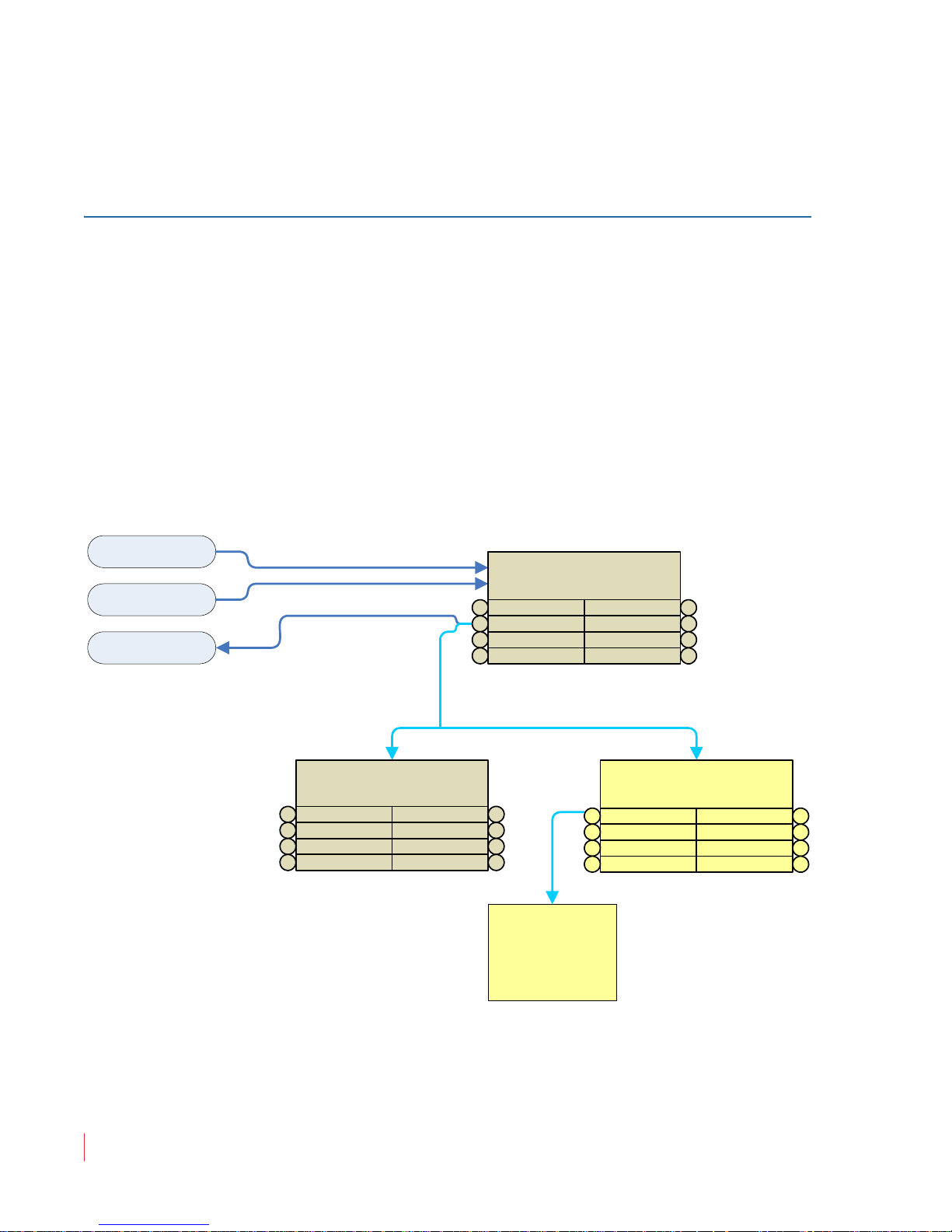
The AMP1-16-3G will display a variety of 3G, HD, and SD video
formats. It supports two 3G SDI inputs that can be alternately selected.
The selected SDI input is reclocked and output.
The video signal paths within the AMP1-16-3G are set up using the
menu screens.
Figure 3–1 illustrates the menus used to modify the video signals, the
various signal inputs, the menus used to configure them, and their
outputs.
Figure 3–1 Video Routing Diagram
821697: AMP1-16 Series User Guide
22
© 2011 Wohler Technologies, Inc. All rights reserved.
 Loading...