

Page 1
2022-D034859
02a
2022-D034859 Revision: 02a
Operating Manual
TK+ ATEX
Page 2

Revision history
Service
In case you have technical questions,
please contact:
WITTENSTEIN alpha GmbH
Customer Service
Walter-Wittenstein-Straße 1
D-97999 Igersheim
Tel.: +49 7931 493-12900
Fax: +49 7931 493-10903
E-mail: [email protected]
© WITTENSTEIN alpha GmbH 2012
This documentation is copyright protected.
WITTENSTEIN alpha GmbH reserves all the rights to photo-mechanical reproduction,
copying, and the distribution by special processes (such as computers, file media, data
networks), even in parts.
Subject to technical and content changes without notice..
Revision Date Comment Chapter
01 18.12.2009 New version All
02 31.08.2010 2-stage design 1, 3, 5, 7, 9
02a 03.12.2012 Translation corrections 2.4, 7.3
TK+ ATEX
2022-D034859 Revision: 02a
Page 3

TK+ ATEX
Contents
1 Regarding this manual.........................................................................................3
1.1 Signal words ........................................................................................................3
1.2 Safety symbols.....................................................................................................3
1.3 Design of the safety instructions ..........................................................................4
1.4 Information symbols.............................................................................................4
2 Safety.....................................................................................................................5
2.1 EC directive for devices and protective systems in areas with
2.2 Dangers ...............................................................................................................5
2.3 Personnel.............................................................................................................5
2.4 Intended use ........................................................................................................5
2.5 Reasonably predictable misuse ...........................................................................6
2.6 Guarantee and liability .........................................................................................6
2.7 General safety instructions ..................................................................................6
3 Description of the gearhead................................................................................9
3.1 Type plate ............................................................................................................9
3.1.1 Atex identification in gas atmospheres with explosion hazard ......................10
3.1.2 Atex identification in dust-air atmosphere with explosion hazard..................10
3.2 Ordering code ....................................................................................................10
3.3 Performance statistics........................................................................................10
3.4 Dimensioning .....................................................................................................11
3.4.1 Inspection ......................................................................................................11
3.5 Weight................................................................................................................11
3.6 Noise emission...................................................................................................11
explosion hazards ................................................................................................5
4 Transport and storage.......................................................................................12
4.1 Scope of delivery ...............................................................................................12
4.2 Packaging ..........................................................................................................12
4.3 Transport............................................................................................................12
4.4 Storage ..............................................................................................................12
5 Assembly ............................................................................................................13
5.1 Preparations.......................................................................................................13
5.2 Installation conditions ........................................................................................13
5.3 Mounting the motor onto the gearhead..............................................................13
5.4 Mounting gearhead on a machine .....................................................................15
5.5 Mounting on the output side...............................................................................15
6 Startup and operation........................................................................................16
6.1 Note during startup ............................................................................................16
6.2 Inadmissible operational conditions ...................................................................17
6.3 Check running-in behavior .................................................................................17
7 Maintenance and disposal.................................................................................18
7.1 Maintenance work..............................................................................................18
7.1.1 Visual/Noise inspection .................................................................................18
7.1.2 Checking the tightening torques....................................................................18
7.1.3 Check for leakage .........................................................................................18
7.1.4 Replacing the gearhead ................................................................................18
7.2 Startup after maintenance work .........................................................................19
7.3 Maintenance schedule .......................................................................................19
7.4 Notes on the lubricant used ...............................................................................19
7.5 Disposal .............................................................................................................19
8 Malfunctions.......................................................................................................20
9 Appendix.............................................................................................................21
9.1 Specifications on mounting onto a motor...........................................................21
Revision: 02a 2022-D034859 en-1
Page 4

TK+ ATEX
9.2 Specifications on mounting onto a machine...................................................... 22
9.3 Specifications on mounting on the gear output side.......................................... 22
9.4 Tightening torques for common thread sizes in general mechanics ................. 22
9.5 Technical specifications ................................................................................... 23
9.5.1 Technical specifications for TK
explosion hazards......................................................................................... 23
9.5.2 Technical specifications for TK
explosion hazards......................................................................................... 25
9.5.3 Technical specifications for TK
explosion hazards......................................................................................... 28
9.5.4 Technical specifications for TK
explosion hazards......................................................................................... 30
9.5.5 Technical specifications for TK
explosion hazards......................................................................................... 33
9.6 Lubricant quantity.............................................................................................. 35
9.7 Declaration of Conformity.................................................................................. 36
+
004 for use in areas with
+
010 for use in areas with
+
025 for use in areas with
+
050 for use in areas with
+
110 for use in areas with
en-2 2022-D034859 Revision: 02a
Page 5
TK+ ATEX Regarding this manual
1 Regarding this manual
These instructions contain necessary information for the safe operation of the angle gear TK+ in
areas with explosion hazards, referred to as gearhead in the following.
The operator must make sure that this operating manual is read through by all persons assigned to
install, operate, or maintain the gearhead, and that they understand them.
Store these instructions within reach near the gearhead.
These safety instructions should be shared with colleagues working in the vicinity of the device
to ensure individual safety.
The original instructions were prepared in German; all other language versions are translations of
these instructions.
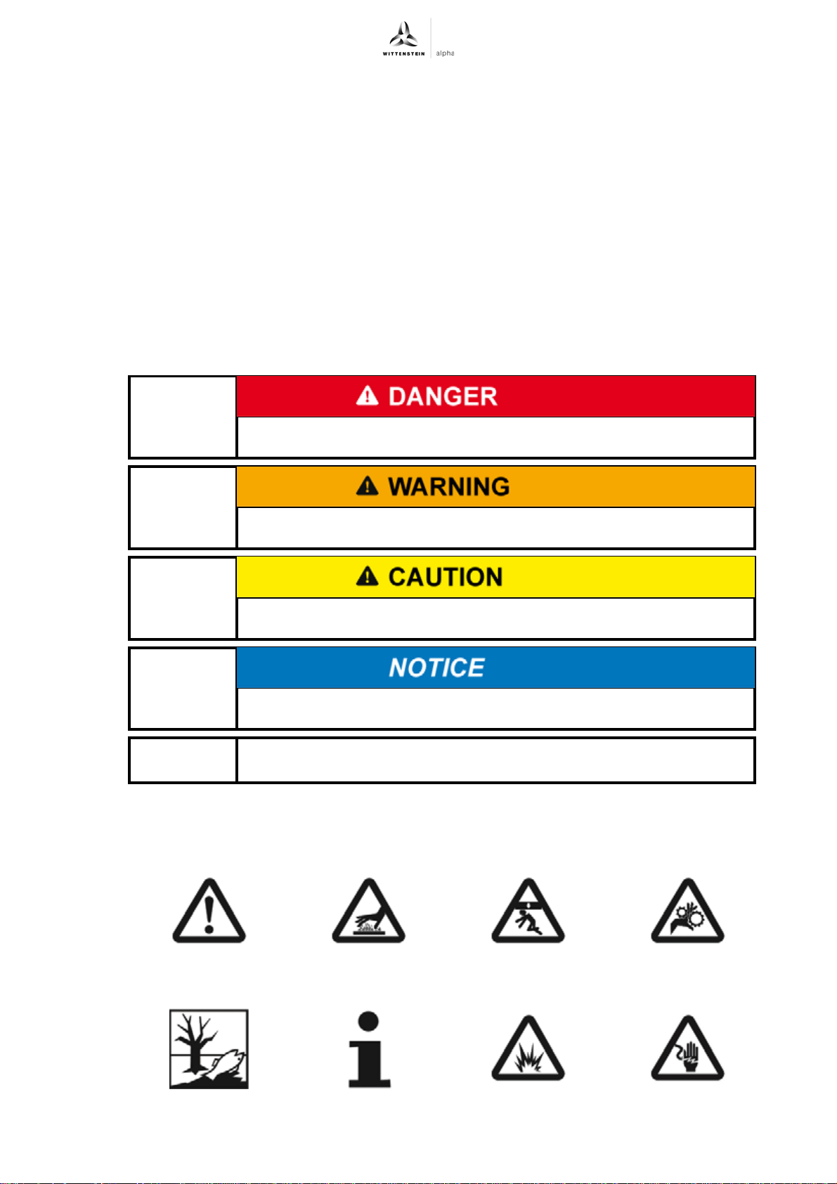
1.1 Signal words
The following signal words are used to bring your attention to dangers, prohibitions, and important
information:
This signal word points out to an imminent danger that can cause
serious injuries and even death.
1.2 Safety symbols
The following safety symbols are used to bring your attention to dangers, prohibitions, and
important information:
This signal word points out to a possible danger that can cause
serious injuries and even death.
This signal word points out to a possible danger that can cause slight
to serious injuries.
This signal word points out to a possible danger that can cause
material damage.
A note without signal word draws your attention to application tips or
especially important information when handling the gearhead.
General danger Hot surface Suspended loads Danger of being
pulled in
Environment protection Information Explosion Electric voltage
Revision: 02a 2022-D034859 en-3
Page 6
Regarding this manual TK+ ATEX
1.3 Design of the safety instructions
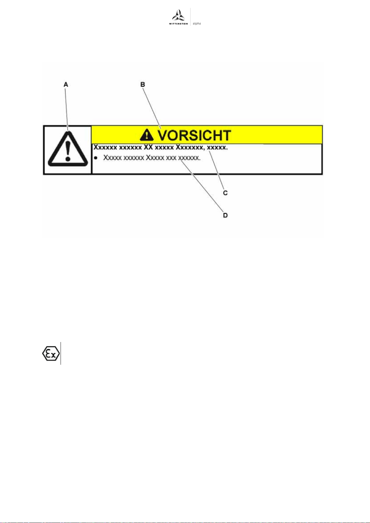
The safety instructions of this operating manual are designed according to the following pattern:
A = Safety symbol (see Chapter 1.2 "Safety symbols")
B = Signal word (see Chapter 1.1 "Signal words")
C = Type and consequence of the danger
D = Prevention of the danger
1.4 Information symbols
The following information symbols are used:
requires you to carry out an action
indicates the results of an action
provides additional information on handling
An "explosion protection symbol" indicates information on handling in areas with
explosion hazards.
en-4 2022-D034859 Revision: 02a
Page 7
TK+ ATEX Safety
2 Safety
These instructions, especially the safety instructions and the rules and regulations valid for the
operating site, must be observed by all persons working with the gearhead.
In addition to the safety specifications mentioned in this operating manual, the general and also the
local regulations on the prevention of accidents and on environmental protection should be
observed.
2.1 EC directive for devices and protective systems in areas with explosion hazards
Within terms of the EC machinery directive 94/9 EC, the gearhead is considered a
device that is mounted together with other devices in a machine. A declaration of
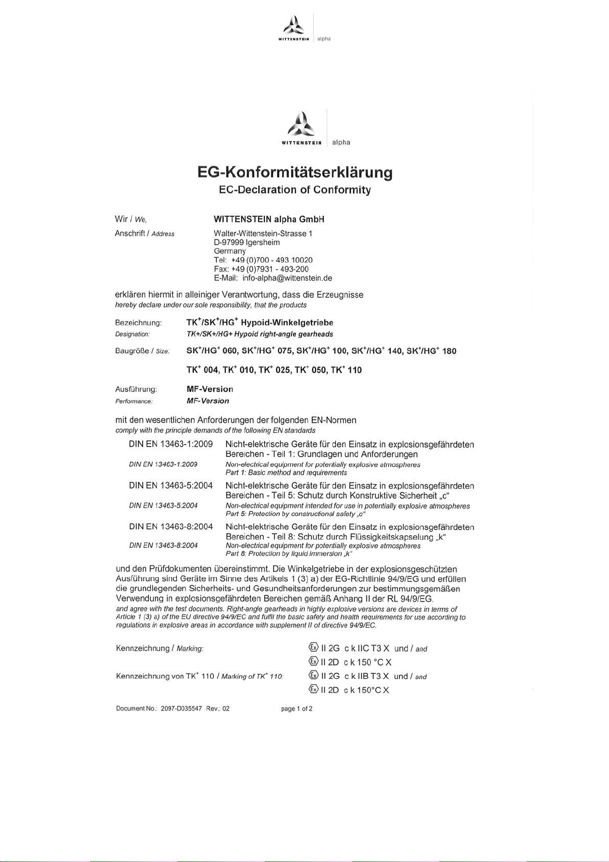
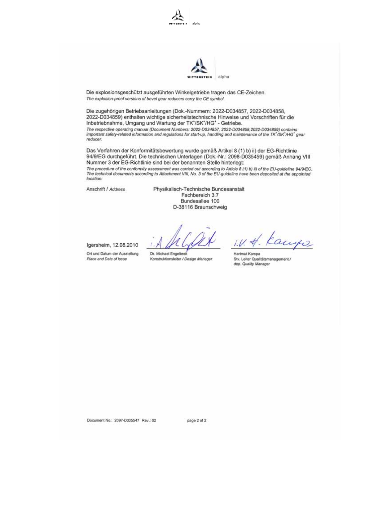
conformity for this gearhead can be found in the appendix (see Chapter 9.7
"Declaration of Conformity").
Operation is prohibited within the area of validity of the EC directive until it has been
determined that the machine in which this product is installed corresponds to the
regulations within this directive.
2.2 Dangers
The gearhead has been constructed according to current technological standards and accepted
safety regulations.
To avoid danger to the operator or damage to the machine, the gearhead may be put to use only
for its intended usage (see chapter 2.4 "Intended use") and in a technically flawless and safe state.
Be informed of the general safety instructions before beginning work. (see Chapter 2.7
"General safety instructions").
2.3 Personnel
Only persons who have read and understood these instructions may carry out work on the
gearhead.
2.4 Intended use
The gearhead serves to convert torques and speeds. It is designed for industrial applications.
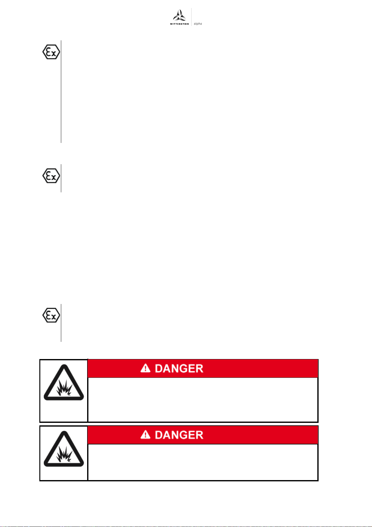
The gear reducer can be used in areas with explosion hazard group II, zones 1 and
2, and zones 22 and 21, thus in the device categories 2 and 3. The gearhead can be
operated in a gas atmosphere in temperature class T3. In dust atmosphere, a
maximum surface temperature of 150°C is possible.
Observe the instructions on the type plate and the appendix on the written
certificate of conformity.
The gearhead is manufactured and declared applying EN 13463 standards and the
94/9/EC directive for use in areas with explosion hazard.
It is imperative that you observe the restrictions of speeds and torques (see
Chapter 9.5 "Technical specifications").
Please consult our Customer Service Department [technical customer service] if
you have any questions or need explanations.
Revision: 02a 2022-D034859 en-5
Page 8
Safety TK+ ATEX
The gearhead is specified for installment on motors that:
- correspond to the design B5 (for any divergences, please consult our Customer
Service Department [technical customer service])
- show a radial and axial runout tolerance of at least “N” according to DIN 42955
- have a smooth shaft
- feature at least the same temperature class as the gearhead.
We recommend temperature class T3 and higher, because the gearhead may
not be permitted to heat up to more than 90 °C in normal conditions. The
gearhead can be heated additionally through heat connection to the motor, and
thus reach a higher housing temperature than 90 °C. The performance of our
gearhead in explosion-risk areas would therefore no longer be guaranteed.
2.5 Reasonably predictable misuse
Any use transgressing the maximum permitted speeds, torques and temperature
(especially ignoring the regulations on explosion protection) is not compliant with the
regulations, and thus prohibited.
2.6 Guarantee and liability
Guarantee and liability claims are excluded for personal injury and material damage in case of
- Ignoring the information on transport and storage
- Improper use (misuse)
- Improper or neglected maintenance and repair
- Improper assembly / disassembly or improper operation
- Operation of the gearhead when safety devices and equipment are defective
- Operation of the gearhead without lubricant
- Operation of a heavily soiled gearhead
- Operating the gearhead despite leakage or unusual running noises
- Operating the gearhead in an atmosphere whose ignition temperature lies under
the temperature class specified on the type plate.
- Modifications or reconstructions that have been executed without written approval
of WITTENSTEIN alpha GmbH
2.7 General safety instructions
Operating the gearhead in areas for which it is not approved can lead
to explosions that can cause serious injuries and even death.
Make sure that the gearhead is only used in those areas for which it is
permitted according to the identification plate (see Chapter 3.1 "Type
plate").
Assembly and maintenance in areas with explosion hazards can lead
to explosions that can cause serious injuries and even death.
Be certain that there is no explosive atmosphere during assembly and
maintenance.
en-6 2022-D034859 Revision: 02a
Page 9
TK+ ATEX Safety
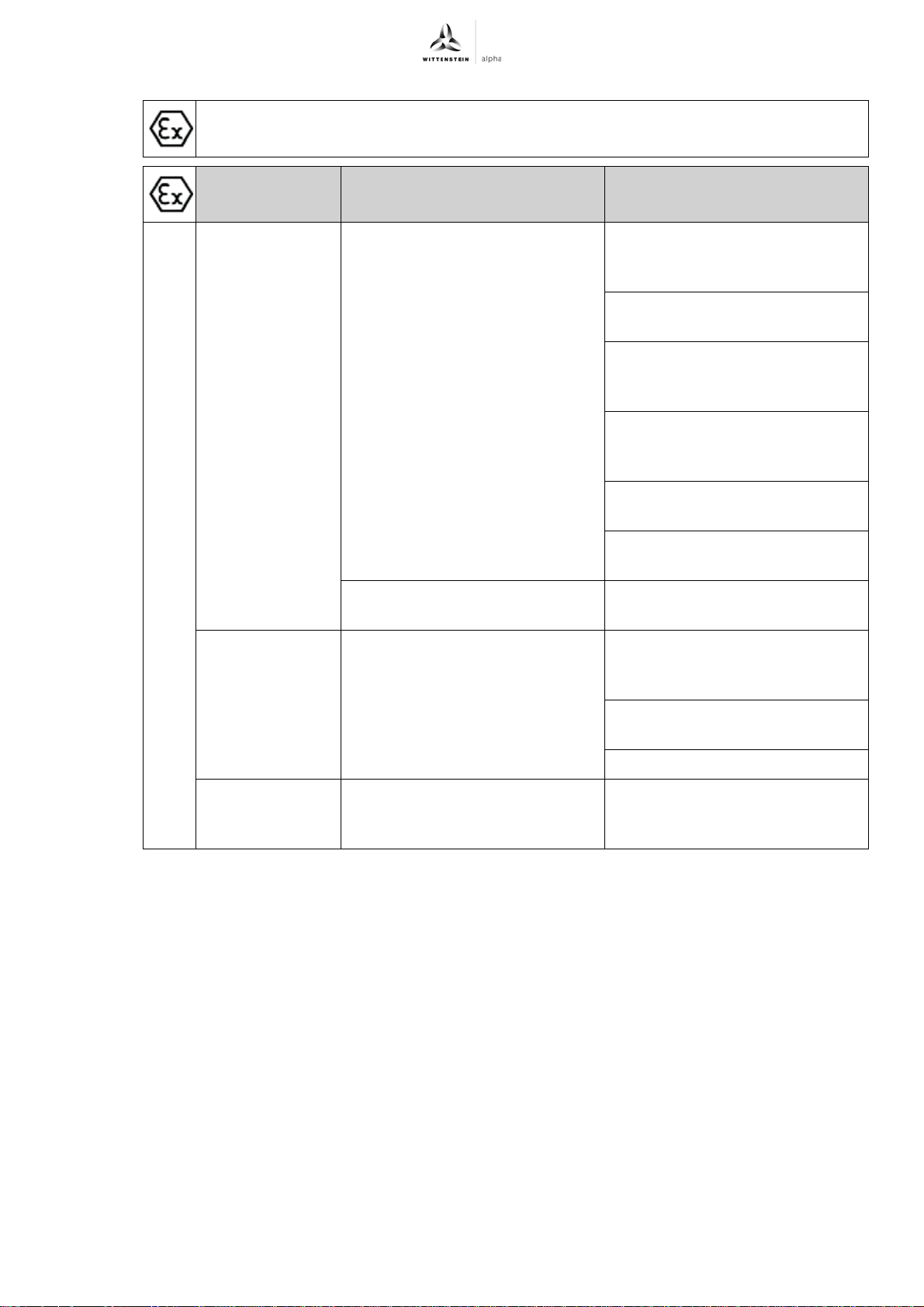
Table "Tbl-1" lists a summary of the possible hazards, their causes and protective
measures for areas with explosion hazards.
Dangers Possible causes Protective measures
Hot surfaces Increased friction and dissipated
power because of wear, improper
assembly, overload, or leaks.
Increased surface temperature
because of dust deposits.
Mechanically
caused sparks
Overload on shafts, moving parts
and connection elements.
Reduction of the torques and
speeds in comparison to standard
gears
Limiting the motor current and
maximum speed of the motor
Maintenance intervals for wear
parts and lubrication according to
maintenance schedule
Inspection of the temperature
behavior and the running-in
behavior before startup
Regular visual and acoustic
inspections
Prohibition of certain mounting
positions and conditions
Cleaning regulations according to
maintenance plan
Reduction of the torques and
external loads in comparison to
standard gears
Limiting the motor current of the
motor
Maximum load test before startup
Electrostatic
loading
Tbl-1: Summary of the hazards and protective measures for areas with explosion hazards
Potential differences between
components, cleaning processes,
insulating layers
Grounding the gearhead and the
motor
Revision: 02a 2022-D034859 en-7
Page 10
Safety TK+ ATEX
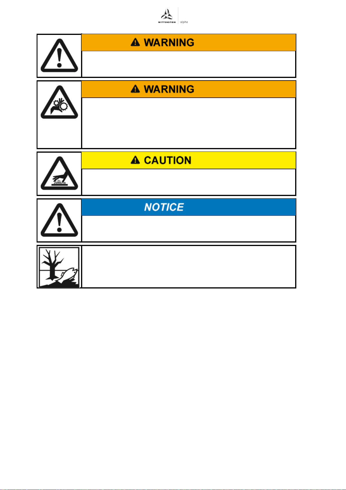
Objects flung out by rotating components can cause serious injuries.
Remove objects and tools from the gearhead before putting it into
operation.
Rotating components on the gearhead can pull in parts of the body
and cause serious injuries and even death.
Keep a sufficient distance to rotating machinery while the gearhead is
running.
Secure the machine against restarting and unintentional movements
during assembly and maintenance work.
Hot gearhead housing can cause serious burns.
Touch the gearhead housing only when wearing protective gloves or
after the gearhead has been at standstill for some time.
Loose or overloaded screw connections can damage the gearhead.
Use a calibrated torque wrench to tighten and check all screw
connections for which tightening torques have been specified.
Solvents and lubricants can pollute soil and water.
Use and dispose of cleaning solvents as well as lubricants appropriately.
en-8 2022-D034859 Revision: 02a
Page 11
TK+ ATEX Description of the gearhead
A
D
E
WITTENSTEIN alpha GmbH - Walter-Wittenstein-Str.1 - 97999 Igersheim
TK+ 025E-MF1-10 -5K1-1K00
i=10
Lubricated for Life: Oil Castrol Tribol 800/220
SN: 1234567 DMF: 34/08 Made in Germany
II 2 G c k IIC T3 X
II 2 D c k 150°C X
T : 480 Nm / n : 2500rpm
2B
1max
C
G
H
I
J
F
B
3 Description of the gearhead
The gearhead is a single- or two-stage, low-backlash angle gear, which is manufactured as
standard in the "M" version (motor installation).
Motor centering is performed:
- up to gearhead size TP
(plug receptacle or coupling)
- from gearhead size TP
the motor
A radial distortion of the motor is avoided.
Adaptation to various motors is done by an adapter plate and a bushing.
The gearhead is equipped with an integrated linear length compensation to compensate for the
expansion of the motor shaft when heated up.
+
025 and a motor shaft diameter of 28 mm by the clamping hub
+
050 and a motor shaft diameter of > 28 mm by the centering collar of
There are two centering mechanisms for the output flange, in
accordance with ISO 9409.
The hollow shaft running through serves as a conduit for lines or
hoses, but does not aid in securing the load. On the back side of the
output flange, the position and/or the speed of the load can be
measured through the hollow shaft.
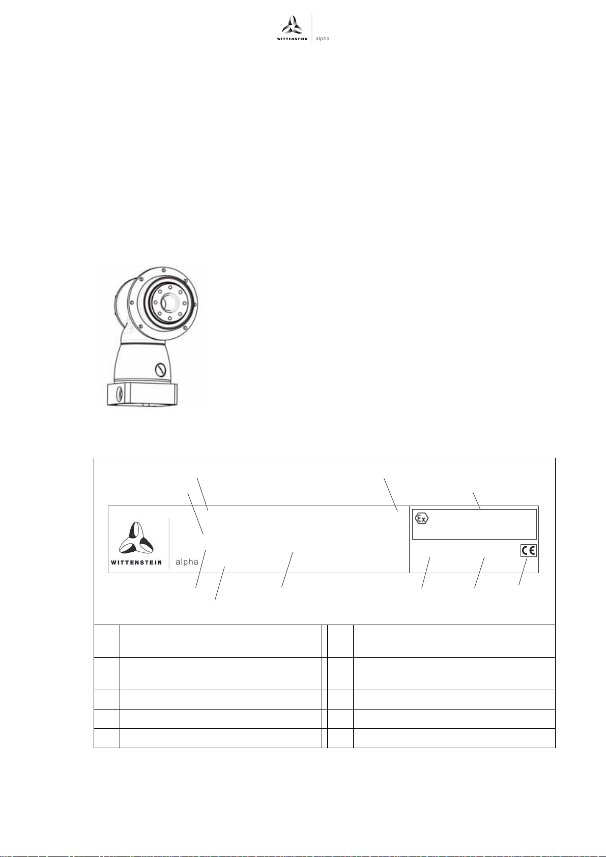
3.1 Type plate
The type plate is attached to the gearhead housing.
A Ordering code (see Chapter 3.2
B Ratio G Maximum permitted gear output torque
C Lubricant H Maximum permitted drive speed n
D Atex identification I CE identification
E Serial number J Name and address of manufacturer
"Ordering code")
F Production date
Tbl-2: Type plate (sample values)
T
2B
1Max
Revision: 02a 2022-D034859 en-9
Page 12
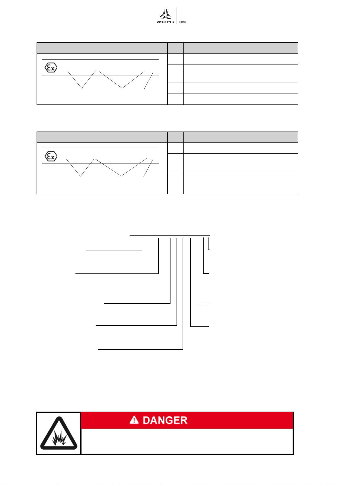
Description of the gearhead TK+ ATEX
L
II2GckIICT3X
M
N
L
II 2 D c k 150°C X
M
N
Gearhead type
TK+ 004/010/025/050/110
Type code
E = Explosion protected according to
94/9/EG
Gearhead variations
M = Motor-mounted gearhead
Gearhead model
F = Standard (for Cyclic duty S5)
Number of Stages
1 = 1-stage
2 = 2-stages
Backlash
1 = Standard
Bore diameters of the
clamping hub
see catalogue
Form of output flange
5 = Hollow shaft flange
Ratio i
TK+ 025E - M F 1-10-5K1
3.1.1 Atex identification in gas atmospheres with explosion hazard Designation
L Group, category
M Type of ignition protection, explosion
group, temperature class
N Ambient temperature
Tbl-3: Type plate (sample values)
3.1.2 Atex identification in dust-air atmosphere with explosion hazard Designation
L Group, category
M Type of ignition protection, maximum
surface temperature
N Ambient temperature
3.2 Ordering code
3.3 Performance statistics
Based on test results, torques and speeds are reduced in relation to the standard gearhead. The
shaft loads are also reduced in relation to the standard gear. Refer to Chapter 9.5 "Technical
specifications".
Tbl-4: Type plate (sample values)
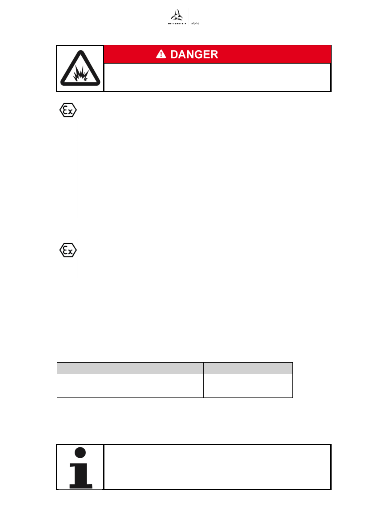
Deviant values can cause the loss of explosion protection.
en-10 2022-D034859 Revision: 02a
If values are divergent, please consult our Customer Service.
Page 13
TK+ ATEX Description of the gearhead
3.4 Dimensioning
Erroneous dimensioning and inspection may lead to loss of explosion
protection.
Please observe all instructions in this chapter.
Adopt the construction according to specifications in the total catalogue, Chapter
"Information" or "Detailed construction", or contact WITTENSTEIN alpha GmbH.
Note the reduced output specifications in construction according to Chapter 9.5
"Technical specifications".
Please consult our Customer Service Department if you have any questions.
Note the instructions in Chapter 7.1.4 "Replacing the gearhead", if the calculated
bearing life is less than 20,000 h.
Prevent gearhead overloading by the motor by limiting motor current and motor
speed.
Clarify the chemical stability of the gearhead for every individual case so as to
avoid a premature failure of a shaft seal or corrosion on the gearhead.
This also includes water and steam, which can cause corrosion. Contact
WITTENSTEIN alpha GmbH about this.
3.4.1 Inspection
Make sure that the connection of the motor to the gearhead corresponds to the
The required protection types can be achieved for example by the following measures:
- Use surface-bonding agent between motor flange and adapter plate.
- Use sealing plates between motor flange and adapter plate to seal the through-holes of the
adapter plate.
Sealing plates are available upon request from WITTENSTEIN alpha GmbH.
3.5 Weight
The table "Tbl-5" specifies the gearhead dimensions with medium-sized adapter plate. If another
adapter plate is mounted, the actual dimensions can deviate by up to 10%.
Gearhead size TK
1–stage [kg] 2,9 5,3 8,9 22,0 48,0
2–stage [kg] 3,2 6,1 10,6 26,0 54,0
required protection types (according to DIN 40050):
- in dust atmosphere IP6x,
- in gas atmosphere IP54.
+
004 010 025 050 110
Tbl-5: Weight
3.6 Noise emission
Depending on the gearhead type and product size, the continuous sound pressure level is up to
68 dB(A) .
Specifications on your specific product can be found in Chapter 9.5
"Technical specifications".
Revision: 02a 2022-D034859 en-11
Page 14
Transport and storage TK+ ATEX
4 Transport and storage
4.1 Scope of delivery
Check the completeness of the delivery against the delivery note.
Missing parts or damage must be notified immediately in writing to the carrier, the
insurance, or WITTENSTEIN alpha GmbH.
4.2 Packaging
The gearhead is delivered packed in foil and cardboard boxes.
Dispose of the packaging materials at recycling sites intended for that. Observe the locally
valid regulations for disposals.
4.3 Transport
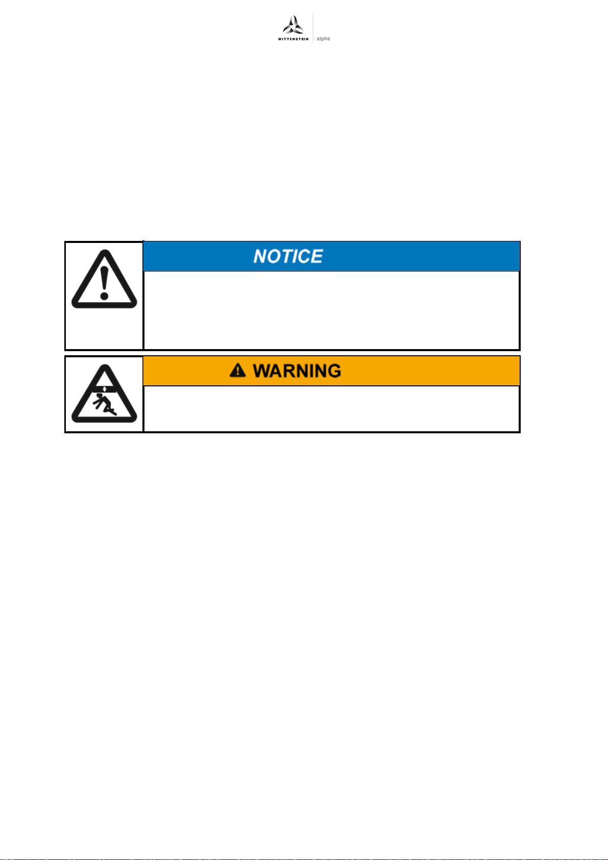
Hard knocks, for instance because of falling or hard dropping, can
damage the gearhead.
Only use hoisting equipment and transports with sufficient capacity.
The maximum permitted lift capacity of a hoist may not be exceeded.
Lower the gearhead slowly.
Specifications on the weights, refer to Chapter 3.5 "Weight".
4.4 Storage
Store the gearhead in horizontal position and dry surroundings at a temperature of 0 °C to +40 °C
in the original packaging. Store the gearhead for a maximum of 2 years.
For storage logistics, we recommend the "first in – first out" method.
Suspended loads can fall and can cause serious injuries and even
death.
Do not stand under suspended loads.
en-12 2022-D034859 Revision: 02a
Page 15
TK+ ATEX Assembly
5 Assembly
Be informed of the general safety instructions before beginning work. (see Chapter 2.7
"General safety instructions").
5.1 Preparations
Pressurized air can damage the gearhead seals.
Do not use pressurized air to clean the gearhead.
Directly sprayed cleaning agents can alter the frictional values of the
clamping hub.
Only spray cleaning agents onto a cloth, with which you can then clean
the clamping hub.
Clean / De-grease the following components with a clean and lint-free cloth and grease-
dissolving, non-aggressive detergent:
- All fitting surfaces to neighboring components
- Centering
- The motor shaft
- The inside diameter of the clamping hub
- The bushing inside and out
Dry all fitting surfaces to neighboring components in order to achieve the proper friction values
of the screw connections.
Check the fitting surfaces additionally for damage and impurities.
5.2 Installation conditions
Provide a metallic frame for connection of the gear reducer.
Provide a ground in the areas of the motor gear and gear-gear connection, so as
to prevent any electrostatic charge that may arise.
5.3 Mounting the motor onto the gearhead
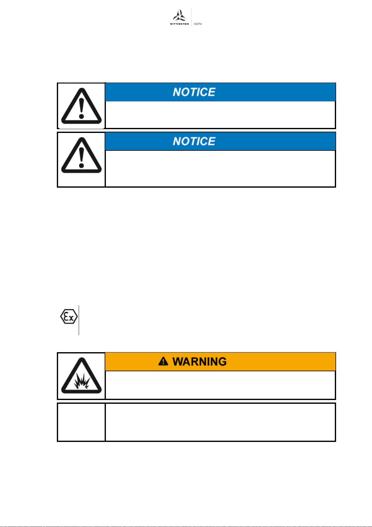
A damaged coupling can cause ignition dangers.
Align the shaft ends of the motor and gearhead precisely. The offset
values in table "Tbl-8" must definitely be maintained.
Observe the general information and safety instructions of the motor
manufacturer.
Observe the safety and processing instructions of the screw-bonding
agents to be used.
Ensure that the motor is mounted if possible in a vertical direction.
Revision: 02a 2022-D034859 en-13
Page 16
Assembly TK+ ATEX
E
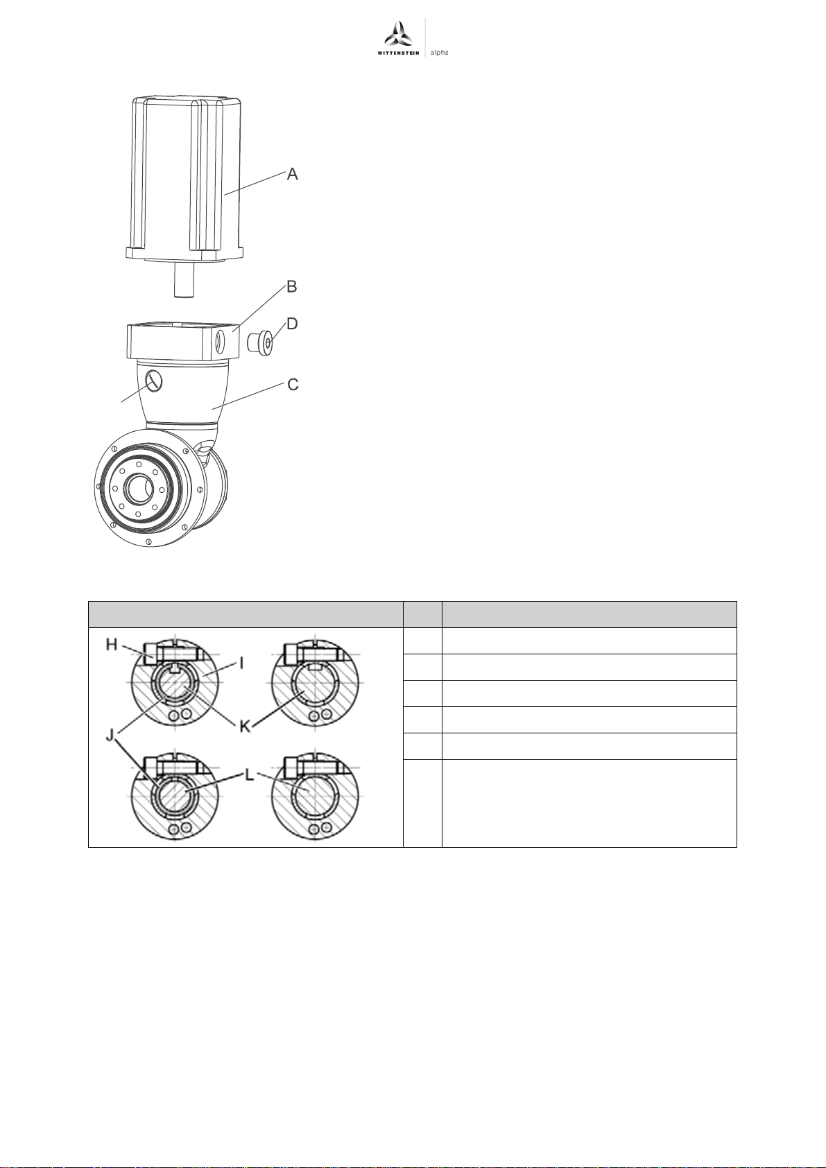
If the motor shaft has a feather key, remove the
feather key.
If recommended by the motor manufacturer,
apply a half wedge.
Remove the plug (D) from the mounting bore in the
adaptor plate (B).
Under no circumstance remove the plug (E) in the
housing.
Turn the clamping hub (I) until the clamping bolt (H)
can be reached over the mounting bore.
Release the clamping bolt (H) of the clamping
hub (I) with one revolution.
Push the motor shaft into the clamping hub of the
gearhead.
The motor shaft should slip in easily. If this is not
the case, the clamping bolt must be loosened
more.
A slotted spacer sleeve has to be installed extra
for certain motor shaft diameters and
applications.
The slot of the spacer sleeve (if provided) and
clamping hub have to be flush with the groove (if
provided) of the motor shaft, see table "Tbl-6".
No gap is premitted between motor (A) and the
adaptor plate (B).
Designation
H Clamping bolt
I Clamping hub
J Spacer sleeve
K Grooved shaft
L Smooth shaft
Tbl-6: Arrangement of motor shaft, clamping hub and spacer sleeve
Apply screw-bonding agent to the four screws (e.g. Loctite 243).
Fasten the motor (A) onto the adaptor plate (B) with the four screws.
If it concerns a single stage gearhead (MF1) , smear screw-bonding agent (for example
Loctite 243) onto the clamping bolt (H).
Tighten the clamping bolt (H) of the clamping hub (I).
For screw sizes and specified torques refer to chapter 9.1 "Specifications on mounting onto
a motor", table "Tbl-12".
Screw in plug (D) of the adaptor plate (B).
For screw sizes and specified torques refer to table "Tbl-7".
en-14 2022-D034859 Revision: 02a
Page 17
TK+ ATEX Assembly
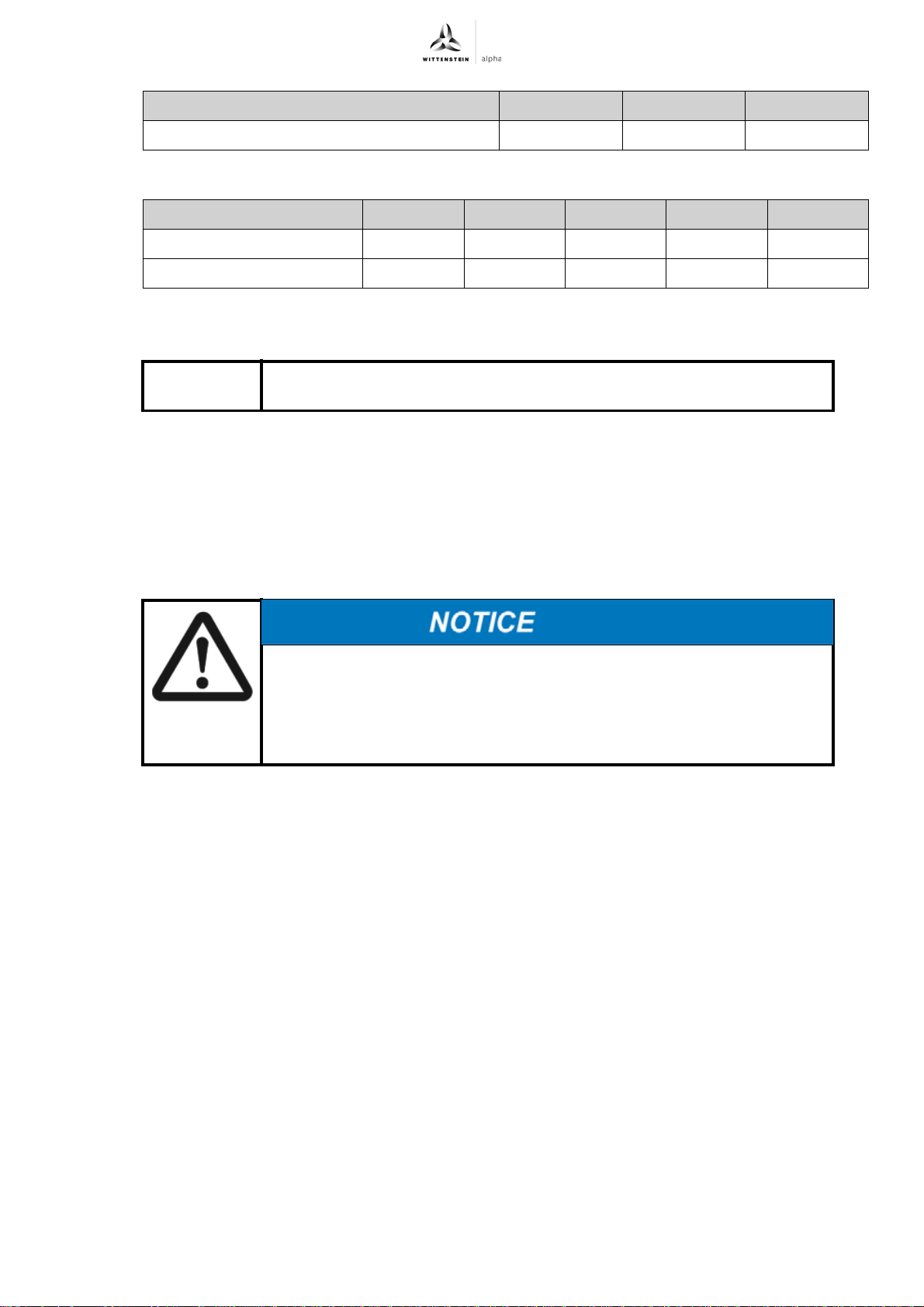
Width across flats [mm] 5 8 10
Tightening torque [Nm] 10 35 50
Tbl-7: Torques for the plugs
Gearhead size TK
+
004 010 025 050 110
Axial offset [mm] ± 0,25 ± 0,3 ± 0,4 ± 0,5 ± 0,6
Angle offset [°] 0,2 0,2 0,2 0,2 0,2
Tbl-8: Permissible offset of the coupling, gearhead singlestaged (MF1)
5.4 Mounting gearhead on a machine
Observe the safety and processing instructions of the screw-bonding
agents to be used.
Smear screw-bonding agent (e.g. Loctite 243) onto the fastening bolts.
Fasten the gearhead on the machine with the bolts through the holes.
Mount the gearhead in such a way that the type plate remains legible.
Do not use washers (e.g. plain washers, tooth lock washers).
For screw sizes and specified torques refer to chapter 9.2 "Specifications on mounting onto
a machine", table "Tbl-13".
5.5 Mounting on the output side
Distortions during mounting operations can damage the gearhead.
Mount gearwheels and toothed belt pulleys onto the output shaft without
forcing.
Do not on any account attempt an assembly by force or hammering!
Only use suitable tools and equipment for assembly.
For screw sizes and specified torques refer to chapter 9.3 "Specifications on mounting on the
gear output side", table "Tbl-14".
Revision: 02a 2022-D034859 en-15
Page 18
Startup and operation TK+ ATEX
6 Startup and operation
Be informed of the general safety instructions before beginning work. (see Chapter 2.7
"General safety instructions").
Operating the gearhead in areas for which it is not approved can lead
to explosions that can cause serious injuries and even death.
Make sure that the gearhead is only used in those areas for which it is
permitted according to the identification plate (see Chapter 3.1 "Type
plate").
Check the gearhead before startup for possible damage, especially the radial shaft seal on
the gear output.
A damaged gearhead can lead to explosions that can cause serious
injuries and even death.
Never operate damaged or abnormally running or sounding gearheads
in an area of explosion hazard.
6.1 Note during startup
Improper use can cause damage to the gearhead and cause ignition dangers.
Make sure that
-the ambient temperature does not drop below 0 °C or exceed +40 °C and
-the operating temperature does not exceed +90 °C.
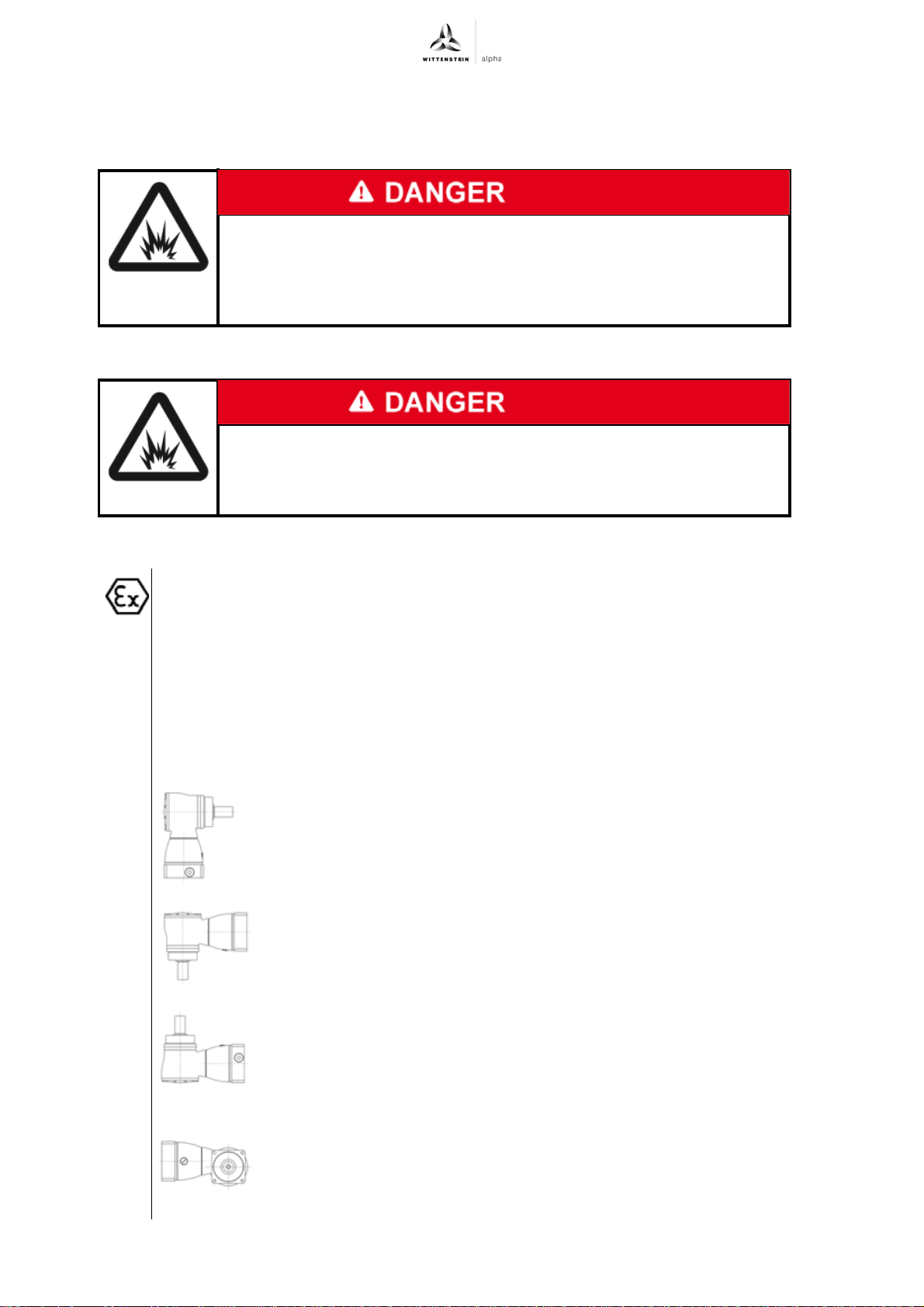
- the gearhead is mounted in the mounting positions depicted below to ensure
the lubrication of all gearhead components.
For other conditions of use and other mounting positions as those depicted below
(e.g. tilting by an axis of these mounting positions), please consult our Customer
Service Department.
Mounting position B5/V3 (output shaft horizontal, motor shaft upwards)
Mounting position V1/B5 (output shaft downwards, motor shaft
horizontal)
Mounting position V3/B5 (output shaft upwards, motor shaft horizontal)
Mounting position B5/B5 (output shaft horizontal, motor shaft
horizontal)
en-16 2022-D034859 Revision: 02a
Page 19
TK+ ATEX Startup and operation
Prevent gear reducer from overloading by limiting the motor current and the
maximum motor speed. Otherwise, the drive output should be switched off in case
the motor temperature rises 10 °C above the usual operational temperature.
Use the gearhead only in a clean and dry environment. Please consult our
Customer Service Department if your gearhead is subjected to course dust or any
kind of liquids during operation.
6.2 Inadmissible operational conditions
The following operational conditions are not permitted:
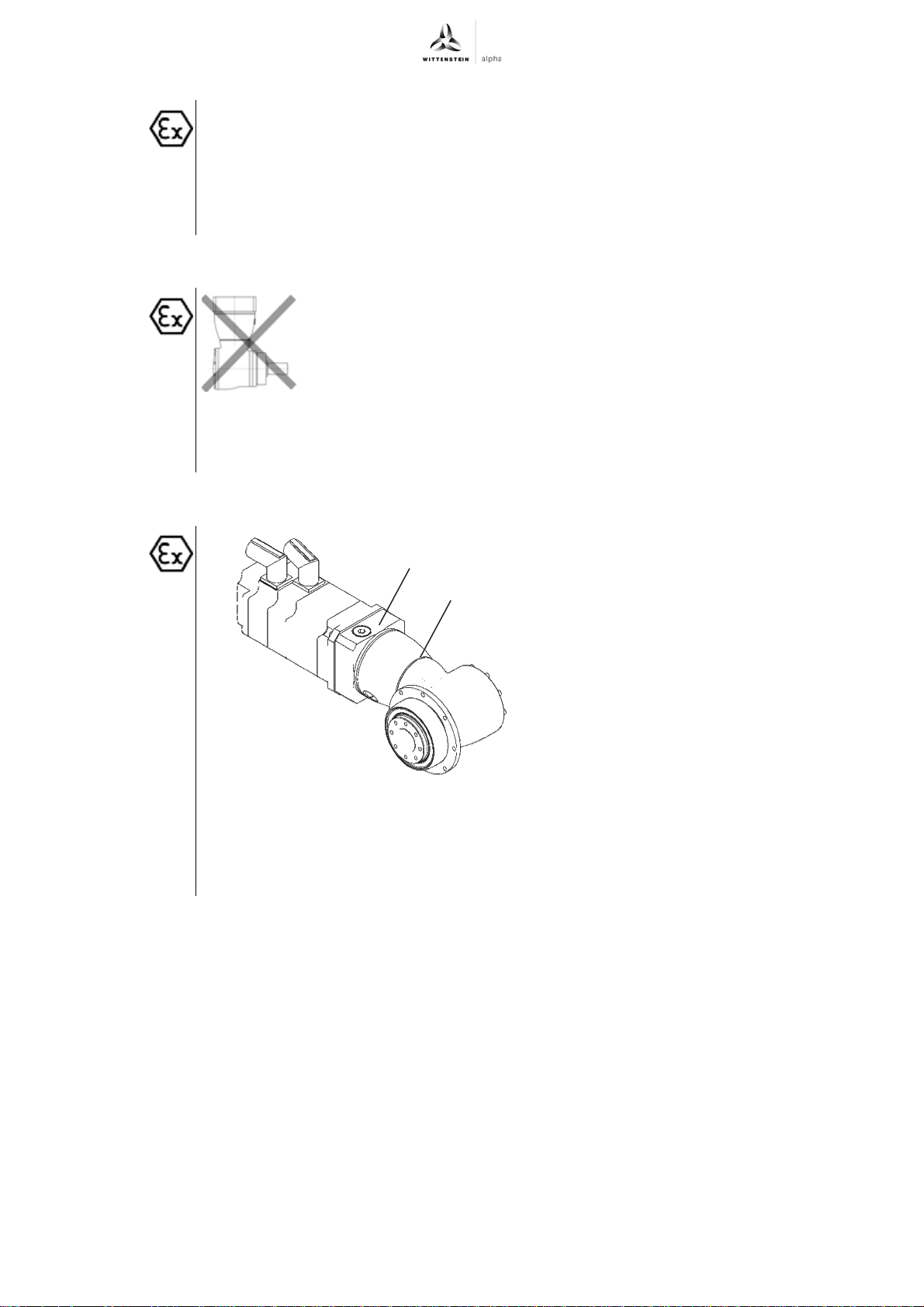
- Mounting position B5/V1 (output shaft horizontal, motor shaft
downwards)
- Co-riding the gearhead on the drive axle is prohibited. Exceptions
require a written approval and technical statement from
WITTENSTEIN alpha GmbH.
- Use during permanent operation (S1 operation: power-on time
greater than 60% or longer than 20 minutes)
6.3 Check running-in behavior
After 4 running hours in maximum
A
operating conditions, check the gearhead
for leakage between gear and motor and
B
on the output shaft seal.
Measure the surface temperature on the
input flange (A) and on the housing (B).
Consult our Customer Service
Department if the temperature exceeds
+90 °C.
Check the proper assembly of the
clamping hub before startup by a
maximum load test.
Increased running noises may be caused by
faulty motor mounting.
If so, mount onto motor again according to
the operating manual, or consult our
Customer Service Department.
Revision: 02a 2022-D034859 en-17
Page 20
Maintenance and disposal TK+ ATEX
7 Maintenance and disposal
Be informed of the general safety instructions before beginning work. (see Chapter 2.7
"General safety instructions").
7.1 Maintenance work
The following maintenance work is crucial for the explosion protection.
Perform these tasks thoroughly and diligently.
7.1.1 Visual/Noise inspection
Dust off the housing. Make sure that the deposit of dust layers on the housing never exceeds
a layer thickness of 5 mm.
Check the entire gearhead for exterior damage and corrosion.
Check the clamping hub for external damage when you inspect the tightening torques of the
clamping bolt.
Check the gearhead for unusual running noises and vibrations during operation.
Please contact our Customer Service if you have any questions regarding maintenance.
7.1.2 Checking the tightening torques
Check the tightening torque of the fastening bolts on the gearhead housing.
You can find the prescribed tightening torques in chapter 9.2 "Specifications on mounting
onto a machine", table "Tbl-13".
Check the tightening torque of the clamping bolt on the motor mounting.
You can find the prescribed tightening torques in chapter 9.1 "Specifications on mounting
onto a motor", table "Tbl-12".
7.1.3 Check for leakage
Check the gear output radial shaft seal for leakage.
Look for external emission of lubricant from the drive.
When opening up the Ermeto coupling, dust could collect on the
adapter plate and catch fire during later operation.
Make sure that no explosive dust-air mixture is present and no dust can
get into adapter plate before opening the Ermeto coupling or dismantling
the motor.
Open up the Ermeto screw connection in the adapter plate and check for any lubricant
emission inside the adapter plate.
If you detect a leak, remove the lubricant and check the inside of the adapter plate once more
after a brief operation. Lubricant discharge should stop after a short time.
In case lubricant still is emitted, shut down the gearhead and consult our Customer Service.
7.1.4 Replacing the gearhead
Replace the gearhead:
- When 90 % of the calculated life of the gear output bearing has been reached (see
"Cymex®" design or total catalogue: Chapter "Information" or "Detailed construction").
- At the latest after a total of 20,000 operating hours.
Alternatively, the gearhead can be checked by WITTENSTEIN alpha GmbH and if
necessary, released for further operation.
en-18 2022-D034859 Revision: 02a
Page 21
TK+ ATEX Maintenance and disposal
7.2 Startup after maintenance work
Clean the outside of the gearhead.
Attach all safety devices.
Do a trial run before releasing the gearhead again for operation.
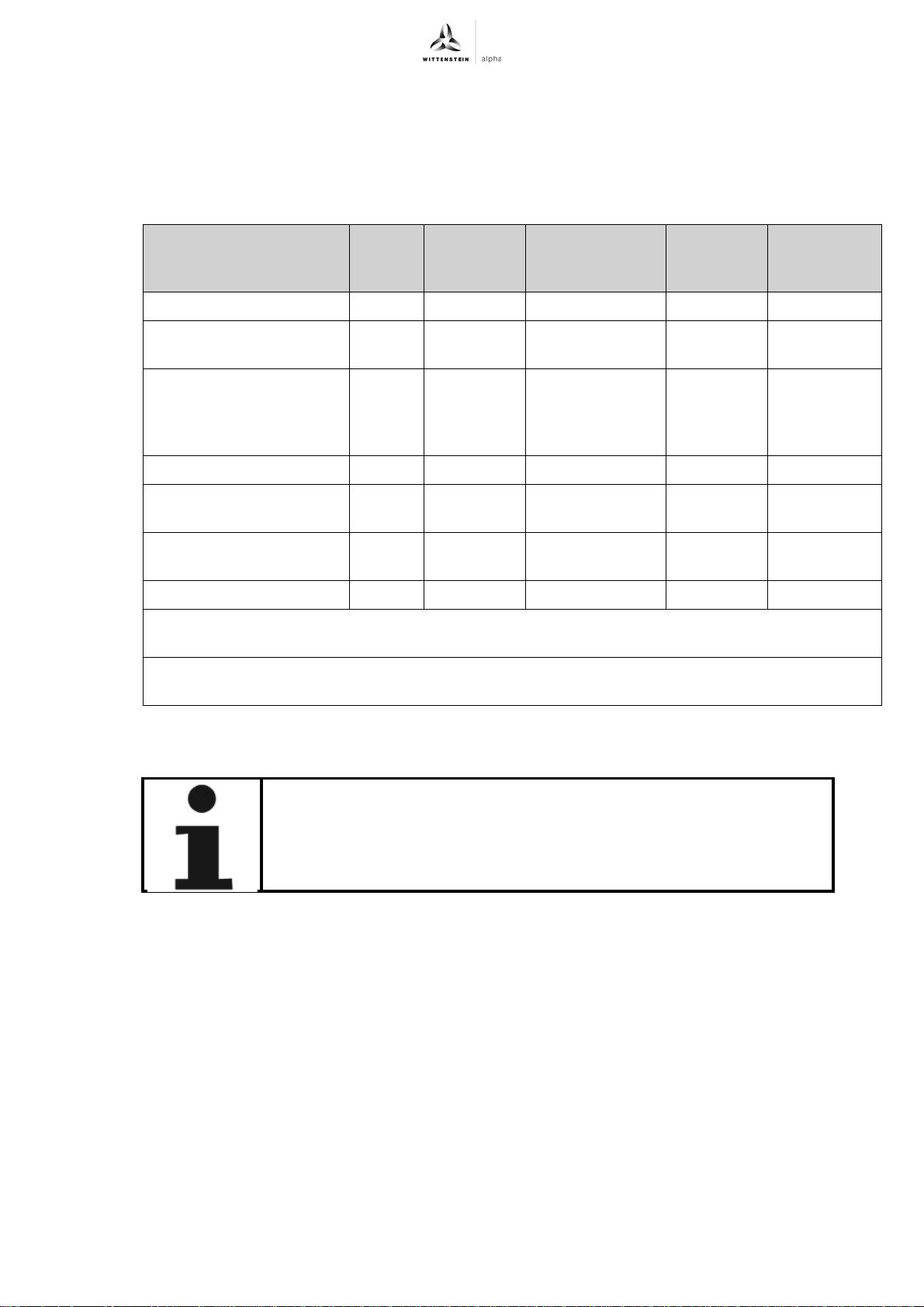
7.3 Maintenance schedule
Maintenance work At
initial
startup
After
running-in
(4 hours)
After every 500
operating hours
or 3 months
Every 5,000
operating
hours
Every 10,000
operating
hours
Visual/Noise inspection XX X - -
Checking the tightening
XX X - -
torques
Check running-in
-X - - -
behavior (see
Chapter 6.3 "Check
running-in behavior")
Check for leakage XX X - -
Exchange the radial shaft
seal on the drive
1)
Exchange the radial shaft
seal on gear output
Perform an oil change
1)
1)
-- - X -
----X
-- - X -
Replace gearhead after reaching 90% of the calculated nominal bearing life, but at the latest after
20,000 operating hours.
1)
Please consult our Customer Service Department concerning this. You will receive the necessary
documents, spare parts, information and upon request training by our Customer Service.
7.4 Notes on the lubricant used All gearheads are filled by the manufacturer with synthetic gear oil
(polyglycols) of viscosity class ISO VG100, ISO VG220.
The lubricant type and quantity can be found in the chapter 9.6
"Lubricant quantity".
The lubricant level lies within its minimal and maximum values in any approved mounting position
with the correct lubricant quantity. The maximum usual pressure that may prevail in the gearhead
during operation lies at 0.5 bar.
You can receive further information on the lubricants directly from the manufacturer:
Castrol Industrie GmbH, Mönchengladbach
Tel.: + 49 (0) 21 61 / 9 09 - 30
7.5 Disposal
Consult our Customer Service Department for supplementary information on exchanging the
adapter plate, on disassembly, and on disposal of the gearhead.
Dispose of the gearhead at the recycling sites intended for this purpose.
Observe the locally valid regulations for disposals.
Tbl-9: Maintenance schedule
Revision: 02a 2022-D034859 en-19
Page 22
Malfunctions TK+ ATEX
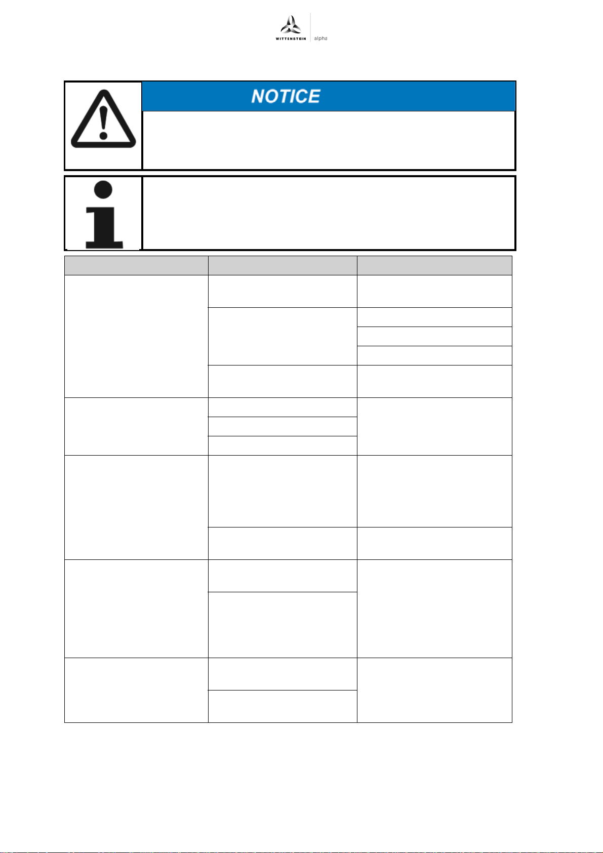
8 Malfunctions
Changed operational behavior can be an indication of existing damage
to the gearhead or cause damage to the gearhead.
Do not put the gearhead back into operation until the cause of the
malfunction has been rectified.
Rectifying of malfunctions may be done by only by especially trained
technicians.
Fault Possible cause Solution
Increased operating
temperature
Increased noises during
operation
Loss of lubricant Lubricant quantity too high Wipe off discharged lubricant
Clamp connection is
slipping
The gearhead is not suited
for the task.
Motor is heating the
gearhead.
Ambient temperature too
high.
Distortion in motor mounting Please consult our Customer
Damaged bearings
Damaged gear teeth
Seals not tight Please consult our Customer
Clamping bolt not tightened
properly
Operating parameters not
maintained
Check the technical
specifications.
Check the wiring of the motor.
Ensure adequate cooling.
Change the motor.
Ensure adequate cooling.
Service Department.
and continue to watch the
gearhead. Lubricant
discharge must stop after a
short time.
Service Department.
Check the shaft seat and hub
bore for damages. Replace
damaged parts. Check the
screw for proper tightening
torque and secure it against
loosening by itself. Check the
operating parameters.
Metal bellows of the
coupling broken
en-20 2022-D034859 Revision: 02a
Operating parameters do not
meet the requirements
Operating errors of the plant
unit
Tbl-10: Malfunctions
Please consult our Customer
Service Department.
Page 23
TK+ ATEX Appendix
9 Appendix
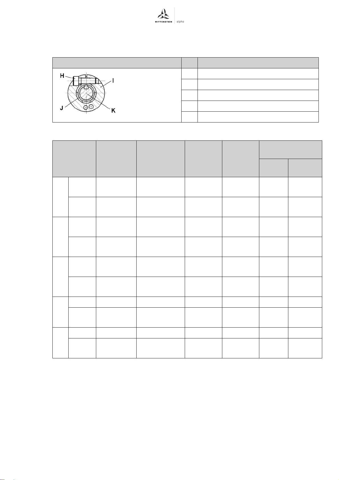
9.1 Specifications on mounting onto a motor
Designation
H Clamping bolt
I Clamping ring (part of the clamping hub)
J Bushing
K Shaft
Tbl-11: Arrangement of motor shaft, clamping hub, and bushing
Gearhead
size
+
TK
004 1–stage x ≤ 14
2–stage x ≤ 11
010 1–stage x ≤ 19
2–stage x ≤ 14
025 1–stage x ≤ 28
2–stage x ≤ 19
Clamping
hub interior
Ø “x”
[mm]
14 < x ≤ 19
11 < x ≤ 14
19 < x ≤ 28
14 < x ≤ 19
28 < x ≤ 38
19 < x ≤ 28
Clamping bolt
(H)/ property
class
DIN ISO 4762
M5 / 10.9
M6 / 10.9
M4 / 12.9
M5 / 12.9
M6 / 10.9
M8 / 10.9
M5 / 12.9
M6 / 12.9
M8 / 10.9
M10 / 10.9
M6 / 12.9
M8 / 12.9
Width
across
flats
[mm]
4
5
3
4
5
6
4
5
6
8
5
6
Tightening
torque
[Nm]
8,5
14
4,1
9,5
14
35
9,5
14
35
69
14
35
max. axial force
clamping hub [N]
Plug-in
Coupling
terminal
—10
80 —
—20
100 —
—30
120 —
050 1–stage x ≤ 38 M10 / 10.9 8 69 — 50
2–stage x ≤ 24
24 < x ≤ 38
110 1–stage x
≤ 48 M12 / 10.9 10 86 — 200
2–stage x ≤ 38
38 < x ≤ 48
Revision: 02a 2022-D034859 en-21
M8 / 12.9
M10 / 12.9
M10 / 12.9
M12 / 12.9
Tbl-12: Specifications on mounting onto a motor
6
8
8
10
35
79
79
135
150 —
200 —
Page 24
Appendix TK+ ATEX
9.2 Specifications on mounting onto a machine Through-holes in gearhead housing
Size /
Version
Hole circle Ø
[mm]
Quantity x
diameter
For screw size/
property class
[ ] x [mm]
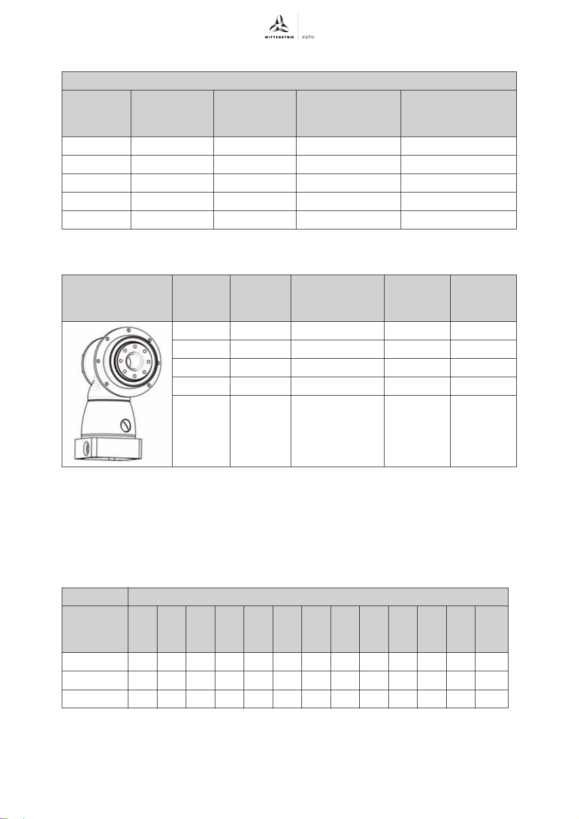
004 79 8 x 4,5 M4 / 12.9 4,55
010 109 8 x 5,5 M5 / 12.9 9,0
025 135 8 x 5,5 M5 / 12.9 9,0
050 168 12 x 6,6 M6 / 12.9 15,4
110 233 12 x 9,0 M8 / 12.9 37,3
Tbl-13: Specifications on mounting onto a machine
9.3 Specifications on mounting on the gear output side Size /
Design
+
TK
Hole
circle Ø
[mm]
Quantity x
thread x depth
[ ] x [mm] x [mm]
004 31,5 8 x M5 x 7 12.9 9,0
010 50 8 x M6 x 10 12.9 15,4
025 63 12 x M6 x 12 12.9 15,4
Tightening torque
[Nm]
Property
Tightening
class
torque
[Nm]
050 80 12 x M8 x 15 12.9 37,3
110 125 12 x M10 x 20 12.9 73,4
Tbl-14: Thread in output flange
9.4 Tightening torques for common thread sizes in general mechanics
The specified tightening torques for headless screws and nuts are calculated values and are based
on the following conditions:
- Calculation acc. VDI 2230 (Issue February 2003)
- Friction value for thread and contact surfaces μ=0.10
- Exploitation of the yield stress 90 %
Tightening torque [Nm] for threads
Property
M3 M4 M5 M6 M8 M10 M12 M14 M16 M18 M20 M22 M24
class
Bolt / nut
8.8 / 8 1.15 2.64 5.24 8.99 21.7 42.7 73.5 118 180 258 363 493 625
10.9 / 10 1.68 3.88 7.69 13.2 31.9 62.7 108 173 265 368 516 702 890
12.9 / 12 1.97 4.55 9.00 15.4 37.3 73.4 126 203 310 431 604 821 1042
Tbl-15: Tightening torques for headless screws and nuts
en-22 2022-D034859 Revision: 02a
Page 25
TK+ ATEX Appendix
9.5 Technical specifications
+
9.5.1 Technical specifications for TK
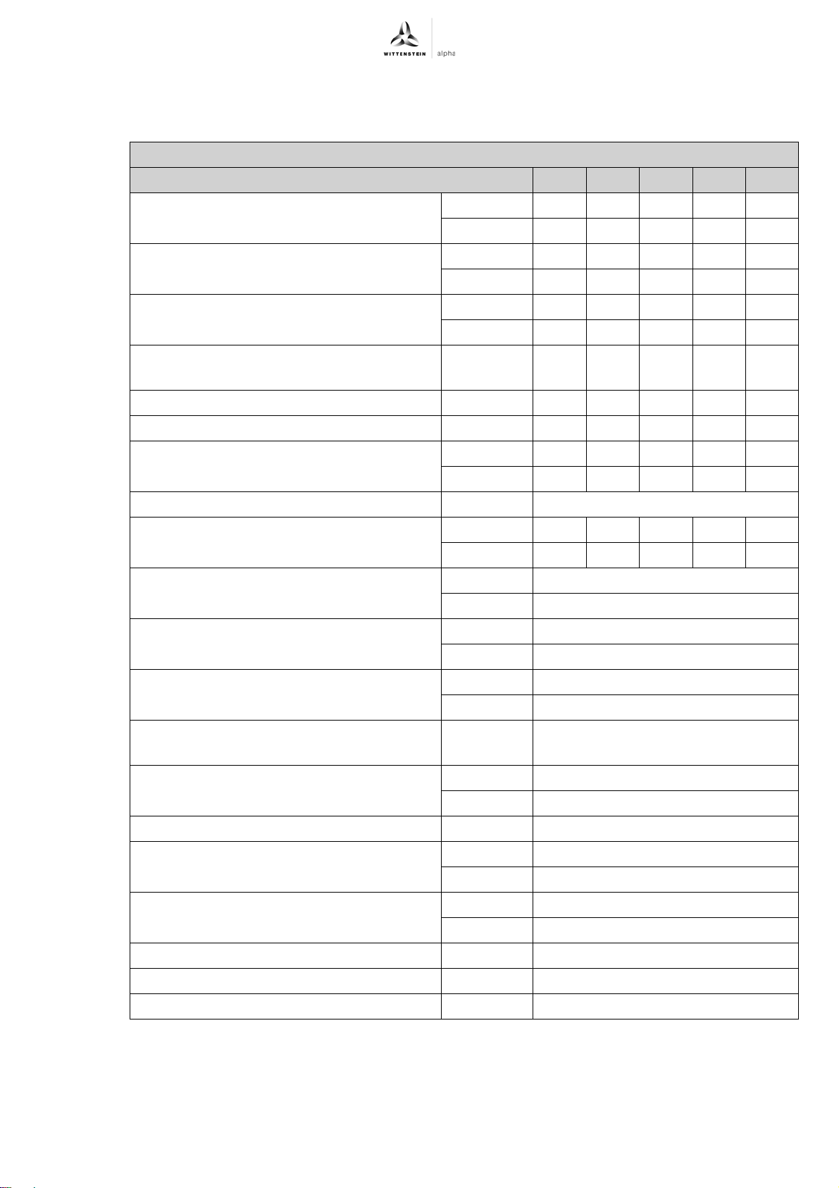
Technical specifications for TK+ 004, 1-stage
Ratio 3 4 5 7 10
004 for use in areas with explosion hazards
Max. acceleration torque T
2B
(max. 1000 cycles per hour)
Nominal torque at gear output T
(At n
Emergency-stop torque T
1N
)
2Not
2N
(1000 times
possible during the lifespan of the gearhead)
012
1N
(At
2N
Permissible medium drive speed in n
(At T
Max. continuous speed n
Max. drive speed n
2N
)
(At 20% T
1Ncym
1Max
Average no-load running torque T
n
=3000 rpm and 20°C gearhead temperature)
1
Max. torsional backlash j
Torsional rigidity C
Max. axial force F
Max. radial force F
2AMax
2RMax
t12
t
b
b
Nm 24 24 24 20 16
in.lb 212 212 212 177 142
Nm 17.5 17.5 17.5 16 12
in.lb 155 155 155 142 106
Nm 40 40 40 40 40
in.lb 354 354 354 354 354
rpm 1800 1900 2200 2200 2200
) rpm 2000 2300 2800 2400 2400
rpm 6000 6000 6000 6000 6000
a
Nm 1.4 1.3 1.2 1.4 1.3
in.lb 12.4 11.5 10.6 12.4 11.5
arcmin < 5
Nm/arcmin 2.6 2.8 3.0 2.6 2.3
in.lb/arcmin 23 25 26 23 20
N 1650
lbf 371
N 1850
lbf 416
Max. tilting moment M
2KMax
Nm 175
in.lb 1549
Life L
h
Calculation see "Technical Basics"
h See chapter
7.1.4 "Replacing the
gearhead"
Weight incl. standard adapter plate m kg 2.9
lbm 6.4
Noise level L
PA
(At n
=3000 rpm w/o load) dB(A) < 64
1
Max. permissible housing temperature °C 90
F 194
Ambient temperature °C 0 to +40
F 32 to 104
Paint Blue RAL 5002
Direction of rotation Drive and gear output counter-directional
Protection class IP 65
Revision: 02a 2022-D034859 en-23
Page 26
Appendix TK+ ATEX
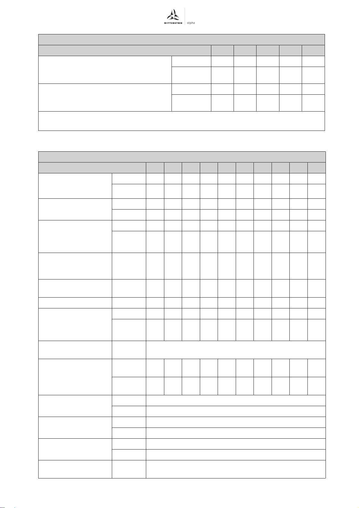
Technical specifications for TK+ 004, 1-stage
Ratio 3 4 5 7 10
2
10
10
kgcm
-3
in.lb.s
kgcm
-3
in.lb.s
0.57 0.46 0.41 0.37 0.35
2
0.50 0.41 0.36 0.33 0.31
2
0.92 0.82 0.76 0.72 0.70
2
0.81 0.72 0.68 0.64 0.62
Mass moment of inertia J1
referring to the drive;
Bore diameters of the clamping hub: 14 mm
Mass moment of inertia J
1
referring to the drive;
Bore diameters of the clamping hub: 19 mm
a
No-load running torques diminish during operation
b
Based on the shaft or flange center at the gear output
Tbl-16: TK+ 004, 1-stage: Technical specifications for use in areas with explosion hazards
Technical specifications for TK+ 004, 2-stage
Ratio 12 16 20 25 28 35 40 50 70 100
Max. acceleration
torque T
cycles per hour)
(max. 1000
2B
Nominal torque at gear
output T
(At n1N)
2N
Emergency-stop torque
T
(1000 times
2Not
possible during the
lifespan of the gearhead)
Permissible medium
drive speed in n
1N
(At T2N)
Max. continuous speed
n
Max. drive speed n
1Ncym
(At 20% T2N)
1Max
Average no-load
running torque T
n
=3000 rpm and 20°C
1
gearhead temperature)
012
(At
a
Max. torsional backlash
j
t
Torsional rigidity C
t12
Nm 24 24 24 24 24 24 24 24 20 16
in.lb 212 212 212 212 212 212 212 212 177 142
Nm 17.5 17.5 17.5 17.5 17.517.517.517.5 16 12
in.lb 155 155 155 155 155 155 155 155 142 106
Nm 40 40 40 40 40 40 40 40 40 40
in.lb 354 354 354 354 354 354 354 354 354 354
rpm
rpm
rpm
3150 3150 3150 3150 3150 3150 3150 3450 3950 3950
3600 3600 3600 3600 3600 3600 3600 3600 3950 3950
6000 6000 6000 6000 6000 6000 6000 6000 6000 6000
Nm 0.2 0.2 0.2 0.2 0.2 0.2 0.1 0.1 0.1 0.1
in.lb 1.8 1.8 1.8 1.8 1.8 1.8 0.9 0.9 0.9 0.9
arcmin ≤ 5
Nm/
2,8 2,8 2,8 2,8 2,8 2,8 2,8 3,0 2,6 2,3
arcmin
in.lb/
25 25 25 25 25 25 25 26 23 20
arcmin
Max. axial force F
2AMax
b
N 1650
lbf 371
Max. radial force F
2RMax
b
N 1850
lbf 416
Max. tilting moment
M
2KMax
Life L
Calculation see
h;
Nm 175
in.lb 1549
h See chapter 7.1.4 "Replacing the gearhead"
"Technical Basics"
en-24 2022-D034859 Revision: 02a
Page 27
TK+ ATEX Appendix
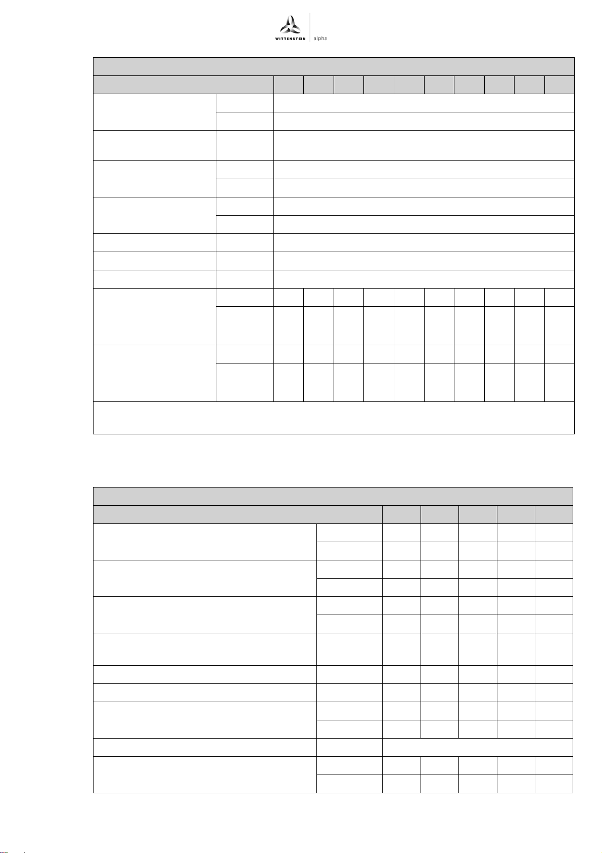
Technical specifications for TK+ 004, 2-stage
Ratio 12 16 20 25 28 35 40 50 70 100
Weight incl. standard
adapter plate m
Noise level L
n
=3000 rpm w/o load)
1
PA
(At
Max. permissible
housing temperature
kg 3.2
lbm 7.1
dB(A) ≤ 64
°C +90
F 194
Ambient temperature °C 0 to +40
F 32 to 104
Paint Blue RAL 5002
Direction of rotation Drive and gear output counter-directional
Protection class IP 65
Mass moment of inertia
J
referring to the drive;
1;
Bore diameters of the
kgcm
-3
10
in.lb.s
2
0,09 0,09 0,08 0,07 0,06 0,06 0,06 0,06 0,06 0,06
0,08 0,08 0,07 0,06 0,06 0,06 0,05 0,05 0,05 0,05
2
clamping hub: 11 mm
2
Mass moment of inertia
referring to the drive;
J
1;
Bore diameters of the
clamping hub: 14 mm
a
No-load running torques diminish during operation
b
Based on the shaft or flange center at the gear output
kgcm
-3
10
in.lb.s
0,21 0,20 0,19 0,19 0,18 0,18 0,17 0,17 0,17 0,17
0,18 0,18 0,17 0,16 0,16 0,16 0,15 0,15 0,15 0,15
2
Tbl-17: TK+ 004, 2-stage: Technical specifications for use in areas with explosion hazards
9.5.2 Technical specifications for TK+ 010 for use in areas with explosion hazards
Technical specifications for TK+ 010, 1-stage
Ratio 3 4 5 7 10
Max. acceleration torque T
2B
(max. 1000 cycles per hour)
Nominal torque at gear output T
(At n
Emergency-stop torque T
1N
)
2Not
2N
(1000 times
possible during the lifespan of the gearhead)
Permissible medium drive speed in n
(At T
Max. continuous speed n
Max. drive speed n
2N
)
(At 20% T
1Ncym
1Max
Average no-load running torque T
n
=3000 rpm and 20°C gearhead temperature)
1
012;
1N
(At
2N
) rpm 2400 2800 3300 2800 2800
a
Nm 70 70 70 60 50
in.lb 620 620 620 531 443
Nm 50 50 50 45 40
in.lb 443 443 443 398 354
Nm 95 95 95 95 95
in.lb 841 841 841 841 841
rpm 2100 2200 2500 2500 2500
rpm 3000 4000 6000 6000 6000
Nm 2.4 2.0 1.8 2.4 2.2
in.lb 21 18 16 21 19
Max. torsional backlash j
Torsional rigidity C
t12
t
arcmin ≤ 4
Nm/arcmin 6.0 7.0 8.0 8.0 8.0
in.lb/arcmin 53 62 71 71 71
Revision: 02a 2022-D034859 en-25
Page 28
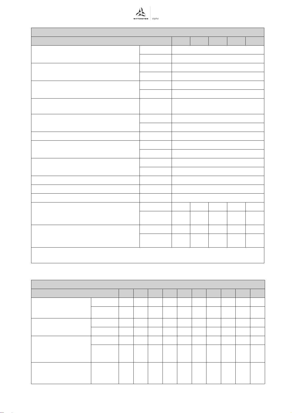
Appendix TK+ ATEX
Technical specifications for TK+ 010, 1-stage
Ratio 3 4 5 7 10
Max. axial force F
Max. radial force F
2AMax
2RMax
b
N 2350
lbf 528
b
N 2800
lbf 630
Max. tilting moment M
2KMax
Nm 300
in.lb 2655
Life L
h
Calculation see "Technical Basics"
h See chapter
7.1.4 "Replacing the
gearhead"
Weight incl. standard adapter plate m kg 5.3
lbm 11.7
Noise level L
PA
(At n
=3000 rpm w/o load) dB(A) ≤ 66
1
Max. permissible housing temperature °C +90
F 194
Ambient temperature ° C 0 to +40
F 32 to 104
Paint Blue RAL 5002
Direction of rotation Drive and gear output counter-directional
Protection class IP 65
Mass moment of inertia J
referring to the drive;
1
10
kgcm
-3
in.lb.s
2
1.81 1.39 1.18 1.02 0.93
2
1.60 1.23 1.05 0.90 0.82
Bore diameters of the clamping hub: 19 mm
2
10
kgcm
-3
in.lb.s
3.22 2.80 2.60 2.43 2.34
2
2.85 2.48 2.30 2.15 2.07
Mass moment of inertia J
referring to the drive;
1
Bore diameters of the clamping hub: 28 mm
a
No-load running torques diminish during operation
b
Based on the shaft or flange center at the gear output
Tbl-18: TK+ 010, 1-stage: Technical specifications for use in areas with explosion hazards
Technical specifications for TK+ 010, 2-stage
Ratio 12 16 20 25 28 35 40 50 70 100
Max. acceleration
torque T
(max. 1000
2B
cycles per hour)
Nominal torque at gear
output T
(At n1N)
2N
Emergency-stop torque
T
(1000 times
2Not
possible during the
Nm 70 70 70 70 70 70 70 70 60 50
in.lb 620 620 620 620 620 620 620 620 531 443
Nm 50 50 50 50 50 50 50 50 45 40
in.lb 443 443 443 443 443 443 443 443 398 354
Nm 95 95 95 95 95 95 95 95 95 95
in.lb 841 841 841 841 841 841 841 841 841 841
lifespan of the gearhead)
Permissible medium
drive speed in n
1N
rpm
3100 3100 3100 3100 3100 3100 3100 3400 4000 4000
(At T2N)
en-26 2022-D034859 Revision: 02a
Page 29
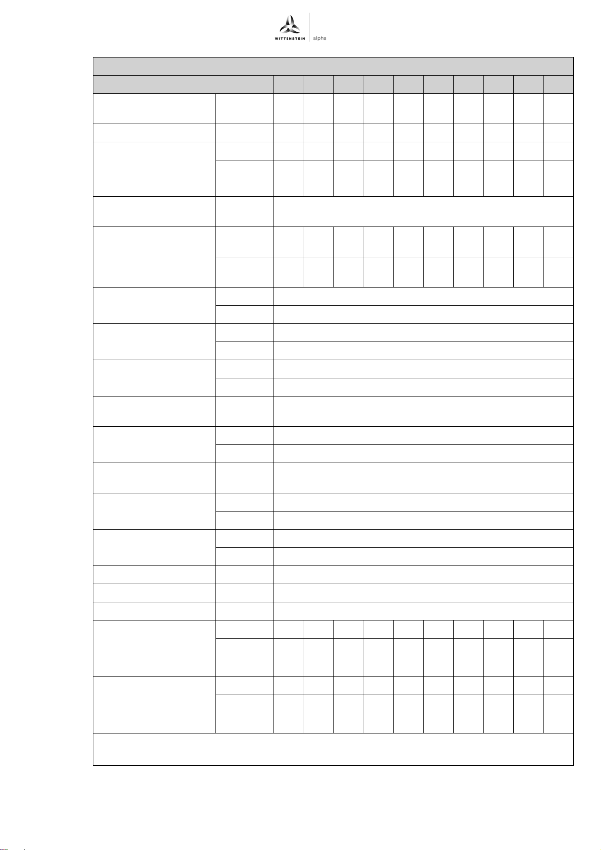
TK+ ATEX Appendix
Technical specifications for TK+ 010, 2-stage
Ratio 12 16 20 25 28 35 40 50 70 100
Max. continuous speed
n
Max. drive speed n
1Ncym
(At 20% T2N)
1Max
Average no-load
running torque T
n
=3000 rpm and 20°C
1
gearhead temperature)
012
(At
a
Max. torsional backlash
j
t
Torsional rigidity C
Max. axial force F
Max. radial force F
t12
2AMax
2RMax
Max. tilting moment
M
2KMax
rpm
rpm
4000 4000 4000 4000 4000 4000 4000 4000 4000 4000
6000 6000 6000 6000 6000 6000 6000 6000 6000 6000
Nm 0.4 0.4 0.3 0.3 0.3 0.3 0.1 0.1 0.1 0.1
in.lb 3.5 3.5 2.7 2.7 2.7 2.7 0.9 0.9 0.9 0.9
arcmin ≤ 4
Nm/
7.0 7.0 7.0 7.0 7.0 7.0 7.0 8.0 8.0 8.0
arcmin
in.lb/
62 62 62 62 62 62 62 71 71 71
arcmin
b
N 2350
lbf 529
b
N 2800
lbf 630
Nm 300
in.lb 2655
Life L
Calculation see
h;
h See chapter 7.1.4 "Replacing the gearhead"
"Technical Basics"
Weight incl. standard
adapter plate m
Noise level L
n
=3000 rpm w/o load)
1
PA
(At
Max. permissible
housing temperature
kg 6.1
lbm 13.5
dB(A) ≤ 66
°C +90
F 194
Ambient temperature °C 0 to +40
F 32 to 104
Paint Blue RAL 5002
Direction of rotation Drive and gear output counter-directional
Protection class IP 65
Mass moment of inertia
J
referring to the drive;
1;
Bore diameters of the
clamping hub: 14 mm
Mass moment of inertia
referring to the drive;
J
1;
Bore diameters of the
clamping hub: 19 mm
a
No-load running torques diminish during operation
b
Based on the shaft or flange center at the gear output
kgcm
-3
10
in.lb.s
kgcm
-3
10
in.lb.s
2
0.31 0.28 0.24 0.23 0.21 0.20 0.19 0.18 0.18 0.18
0.27 0.25 0.21 0.21 0.18 0.18 0.17 0.16 0.16 0.16
2
2
0.75 0.72 0.68 0.68 0.63 0.63 0.63 0.63 0.63 0.63
0.66 0.64 0.61 0.60 0.56 0.55 0.56 0.56 0.55 0.55
2
Tbl-19: TK+ 010, 2-stage: Technical specifications for use in areas with explosion hazards
Revision: 02a 2022-D034859 en-27
Page 30
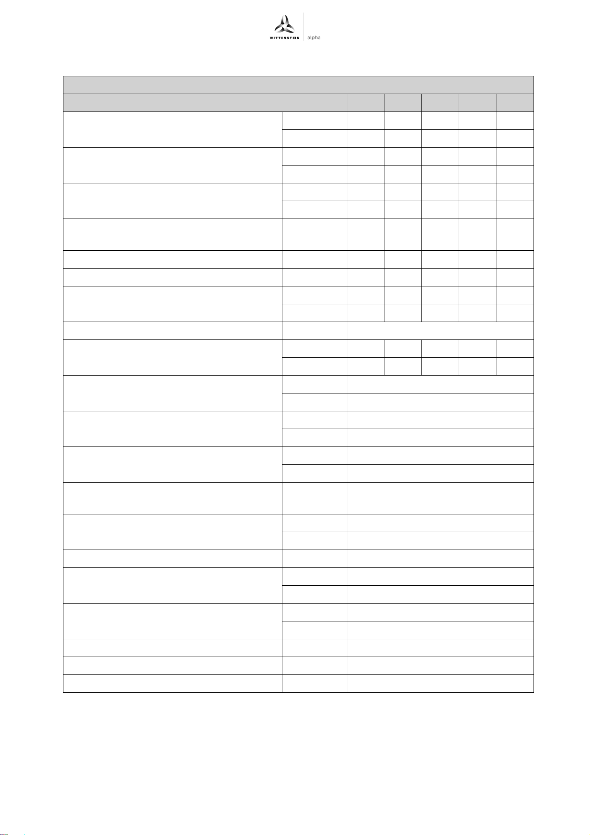
Appendix TK+ ATEX
9.5.3 Technical specifications for TK+ 025 for use in areas with explosion hazards
Technical specifications for TK+ 025, 1-stage
Ratio 3 4 5 7 10
Max. acceleration torque T
2B
(max. 1000 cycles per hour)
Nominal torque at gear output T
(At n
Emergency-stop torque T
1N
)
2Not
2N
(1000 times
possible during the lifespan of the gearhead)
012;
1N
2N
(At
Permissible medium drive speed in n
(At T
Max. continuous speed n
Max. drive speed n
2N
)
(At 20% T
1Ncym
1Max
Average no-load running torque T
n
=3000 rpm and 20°C gearhead temperature)
1
Max. torsional backlash j
Torsional rigidity C
Max. axial force F
Max. radial force F
2AMax
2RMax
t12
t
b
b
Nm 125 125 125 95 85
in.lb 1106 1106 1106 841 752
Nm 75 75 75 60 55
in.lb 664 664 664 531 487
Nm 200 200 200 200 200
in.lb 1770 1770 1770 1770 1770
rpm 1400 1400 1600 1400 1400
) rpm 2100 2100 2100 1600 1500
rpm 2500 3300 4500 4500 4500
a
Nm 4.63.62.84.23.4
in.lb 41 32 25 37 30
arcmin ≤ 4
Nm/arcmin 12 13 16 16 16
in.lb/arcmin 106 115 142 142 142
N 3950
lbf 889
N 2800
lbf 630
Max. tilting moment M
2KMax
Nm 580
in.lb 5133
Life L
h
Calculation see "Technical Basics"
h See chapter
7.1.4 "Replacing the
gearhead"
Weight incl. standard adapter plate m kg 8.9
lbm 20
Noise level L
PA
(At n
=3000 rpm w/o load) dB(A) ≤ 66
1
Max. permissible housing temperature °C +90
F 194
Ambient temperature ° C 0 to +40
F 32 to 104
Paint Blue RAL 5002
Direction of rotation Drive and gear output counter-directional
Protection class IP 65
en-28 2022-D034859 Revision: 02a
Page 31
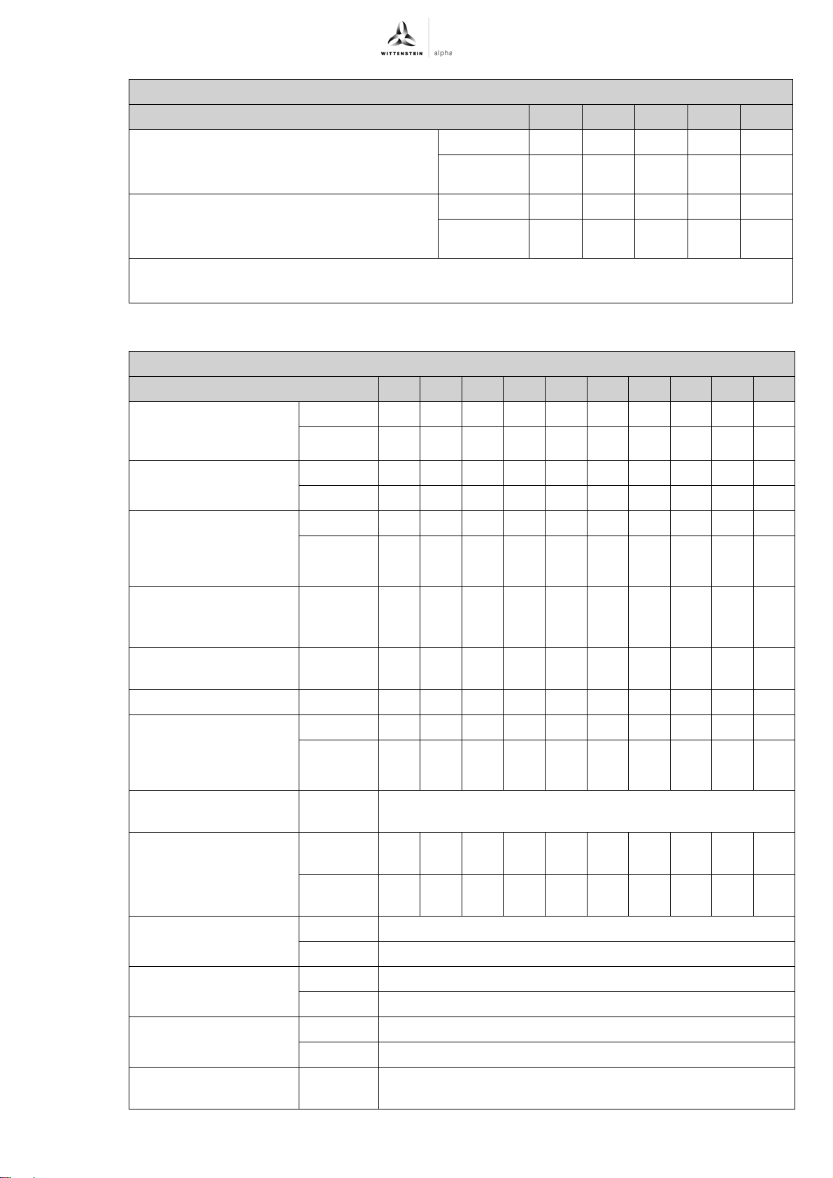
TK+ ATEX Appendix
Technical specifications for TK+ 025, 1-stage
Ratio 3 4 5 7 10
2
10
10
kgcm
-3
in.lb.s
kgcm
-3
in.lb.s
5.46 4.26 3.63 3.13 2.87
2
4.83 3.77 3.22 2.77 2.54
2
12.7 11.5 10.9 10.4 10.1
2
11.2 10.2 9.6 9.2 9.0
Mass moment of inertia J1
referring to the drive;
Bore diameters of the clamping hub: 28 mm
Mass moment of inertia J
1
referring to the drive;
Bore diameters of the clamping hub: 38 mm
a
No-load running torques diminish during operation
b
Based on the shaft or flange center at the gear output
Tbl-20: TK+ 025, 1-stage: Technical specifications for use in areas with explosion hazards
Technical specifications for TK+ 025, 2-stage
Ratio 12 16 20 25 28 35 40 50 70 100
Max. acceleration
torque T
(max. 1000
2B
cycles per hour)
Nominal torque at gear
output T
(At n1N)
2N
Emergency-stop torque
T
(1000 times
2Not
possible during the
lifespan of the gearhead)
Permissible medium
drive speed in n
1N
(At T2N)
Max. continuous speed
n
Max. drive speed n
1Ncym
(At 20% T2N)
1Max
Average no-load
running torque T
n
=3000 rpm and 20°C
1
gearhead temperature)
012;
(At
a
Max. torsional backlash
j
t
Torsional rigidity C
t12
Nm 125 125 125 125 125 125 125 125 95 85
in.lb
1106 1106 1106 1106 1106 1106 1106 1106 841 752
Nm 75 75 75 75 75 75 75 75 60 55
in.lb 664 664 664 664 664 664 664 664 531 487
Nm 200 200 200 200 200 200 200 200 200 200
in.lb
rpm
rpm
rpm
1770 1770 1770 1770 1770 1770 1770 1770 1770 1770
2700 2700 2700 2700 2700 2700 2700 3100 3700 3700
3600 3600 3600 3600 3600 3600 3600 3600 3750 3750
4500 4500 4500 4500 4500 4500 4500 4500 4500 4500
Nm 0.7 0.7 0.6 0.5 0.5 0.4 0.2 0.2 0.2 0.2
in.lb 6.2 6.2 5.3 4.4 4.4 3.5 1.8 1.8 1.8 1.8
arcmin ≤ 4
Nm/
13 13 13 13 13 13 13 16 16 16
arcmin
in.lb/
115 115 115 115 115 115 115 142 142 142
arcmin
Max. axial force F
2AMax
b
N 3950
lbf 889
Max. radial force F
2RMax
b
N 2800
lbf 630
Max. tilting moment
M
2KMax
Life L
Calculation see
h ;
Nm 580
in.lb 5133
h See chapter 7.1.4 "Replacing the gearhead"
"Technical Basics"
Revision: 02a 2022-D034859 en-29
Page 32
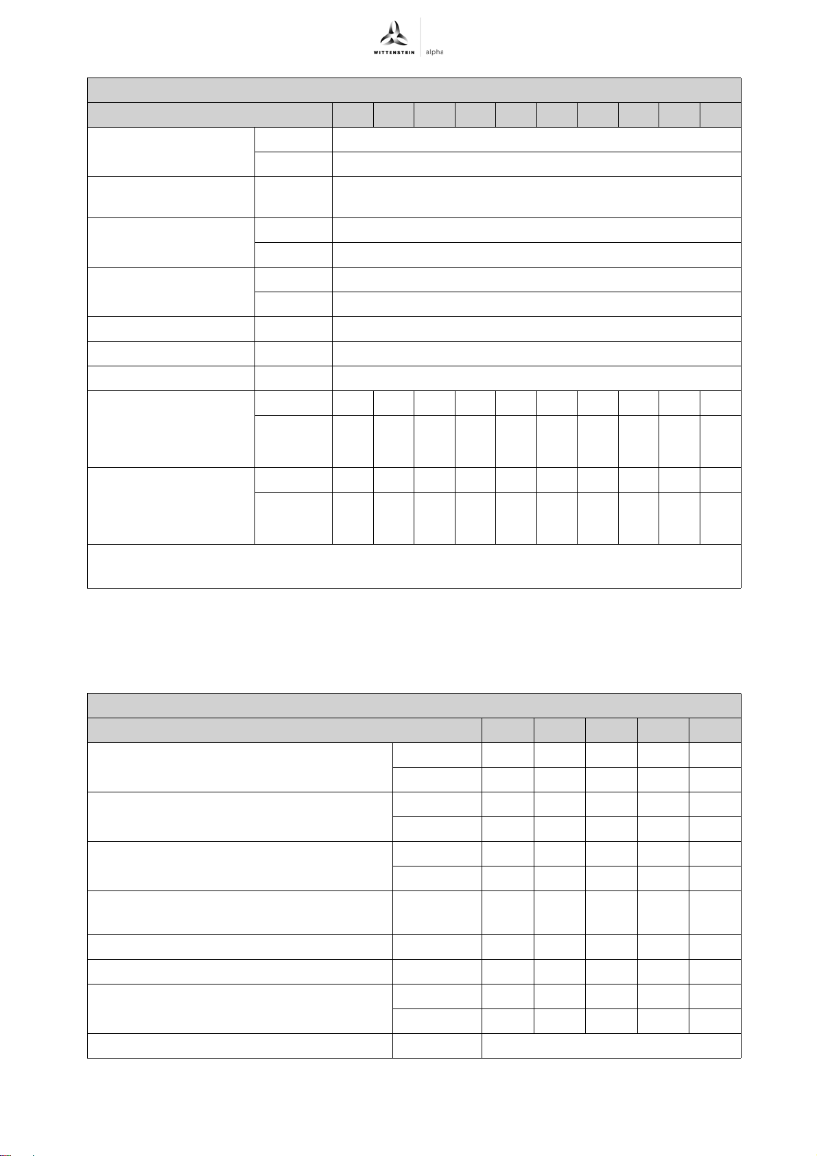
Appendix TK+ ATEX
Technical specifications for TK+ 025, 2-stage
Ratio 12 16 20 25 28 35 40 50 70 100
Weight incl. standard
adapter plate m
Noise level L
n
=3000 rpm w/o load)
1
PA
(At
Max. permissible
housing temperature
kg 10.6
lbm 23
dB(A) ≤ 66
°C +90
F 194
Ambient temperature °C 0 to +40
F 32 to 104
Paint Blue RAL 5002
Direction of rotation Drive and gear output counter-directional
Protection class IP 65
Mass moment of inertia
J
referring to the drive;
1 ;
Bore diameters of the
kgcm
-3
10
in.lb.s
2
1.08 1.01 0.88 0.85 0.76 0.75 0.70 0.69 0.69 0.68
0.96 0.89 0.78 0.75 0.67 0.66 0.62 0.61 0.61 0.60
2
clamping hub: 19 mm
2
Mass moment of inertia
referring to the drive;
J
1 ;
Bore diameters of the
clamping hub: 24 mm
a
No-load running torques diminish during operation
b
Based on the shaft or flange center at the gear output
kgcm
-3
10
in.lb.s
2.65 2.57 2.44 2.42 2.32 2.31 2.26 2.25 2.25 2.25
2.34 2.28 2.16 2.14 2.06 2.05 2.00 2.00 1.99 1.99
2
Tbl-21: TK+ 025, 2-stage: Technical specifications for use in areas with explosion hazards
9.5.4 Technical specifications for TK+ 050 for use in areas with explosion hazards
Technical specifications for TK+ 050, 1-stage
Ratio 3 4 5 7 10
Max. acceleration torque T
2B
(max. 1000 cycles per hour)
Nominal torque at gear output T
(At n
Emergency-stop torque T
1N
)
2Not
2N
(1000 times
possible during the lifespan of the gearhead)
Permissible medium drive speed in n
(At T
Max. continuous speed n
Max. drive speed n
2N
)
(At 20% T
1Ncym
1Max
Average no-load running torque T
n
=3000 rpm and 20°C gearhead temperature)
1
012 ;
1N
2N
(At
) rpm 1500 1600 1800 1600 1700
a
Nm 190 190 205 185 170
in.lb 1682 1682 1814 1637 1505
Nm 120 120 130 130 130
in.lb 1062 1062 1151 1151 1151
Nm 400 420 420 420 400
in.lb 3540 3717 3717 3717 3540
rpm 1200 1200 1400 1300 1400
rpm 2000 2500 3500 4200 4200
Nm 8.46.25.49.06.6
in.lb 74 55 48 80 58
Max. torsional backlash j
t
arcmin ≤ 4
en-30 2022-D034859 Revision: 02a
Page 33
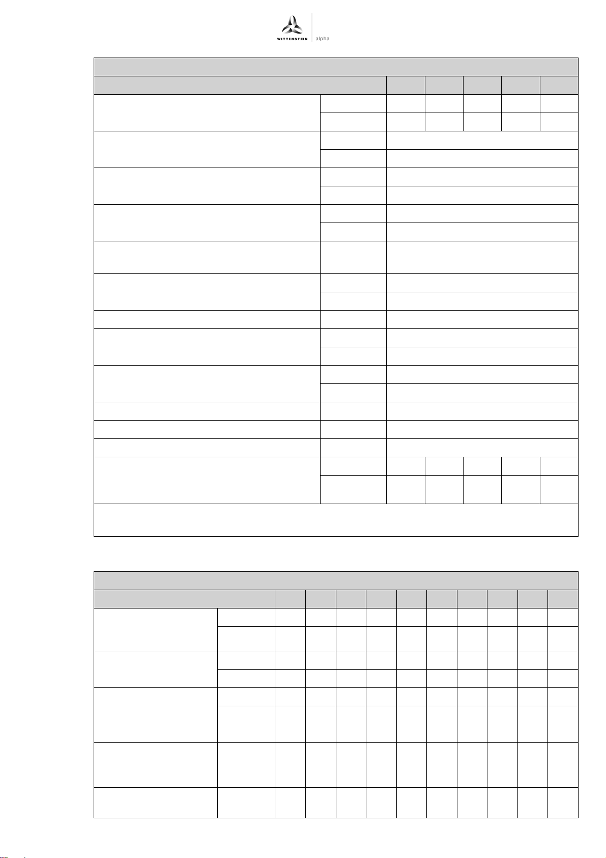
TK+ ATEX Appendix
Technical specifications for TK+ 050, 1-stage
Ratio 3 4 5 7 10
Torsional rigidity C
t12
Nm/arcmin 36 40 46 44 42
in.lb/arcmin 315 356 405 387 376
Max. axial force F
2AMax
b
N 6900
lbf 1553
Max. radial force F
2RMax
b
N 6600
lbf 1485
Max. tilting moment M
2KMax
Nm 1180
in.lb 10443
Life L
h
Calculation see "Technical Basics"
h See chapter
7.1.4 "Replacing the
gearhead"
Weight incl. standard adapter plate m kg 22.0
lbm 49
Noise level L
PA
(At n
=3000 rpm w/o load) dB(A) ≤ 68
1
Max. permissible housing temperature °C +90
F 194
Ambient temperature °C 0 to +40
F 32 to 104
Paint Blue RAL 5002
Direction of rotation Drive and gear output counter-directional
Protection class IP 65
Mass moment of inertia J
referring to the drive;
1
10
kgcm
-3
in.lb.s
2
28.4 21.0 17.6 14.7 13.1
2
25.1 18.6 15.5 13.0 11.6
Bore diameters of the clamping hub: 38 mm
a
No-load running torques diminish during operation
b
Based on the shaft or flange center at the gear output
Tbl-22: TK+ 050, 1-stage: Technical specifications for use in areas with explosion hazards
Technical specifications for TK+ 050, 2-stage
Ratio 12 16 20 25 28 35 40 50 70 100
Max. acceleration
torque T
(max. 1000
2B
cycles per hour)
Nominal torque at gear
output T
(At n1N)
2N
Emergency-stop torque
T
(1000 times
2Not
possible during the
Nm 190 190 190 205 190 205 190 205 185 170
in.lb
1682 1682 1682 1814 1682 1814 1682 1814 1637 1505
Nm 120 120 120 120 120 120 120 130 130 130
in.lb
1062 1062 1062 1062 1062 1062 1062 1151 1151 1151
Nm 400 420 420 420 420 420 420 420 420 400
in.lb
3540 3717 3717 3717 3717 3717 3717 3717 3717 3540
lifespan of the gearhead)
Permissible medium
drive speed in n
1N
rpm
2600 2600 2600 2600 2600 2600 2600 2800 2800 3500
(At T2N)
Max. continuous speed
n
1Ncym
(At 20% T2N)
rpm
3500 3500 3500 3500 3500 3500 3500 3700 3700 3700
Revision: 02a 2022-D034859 en-31
Page 34
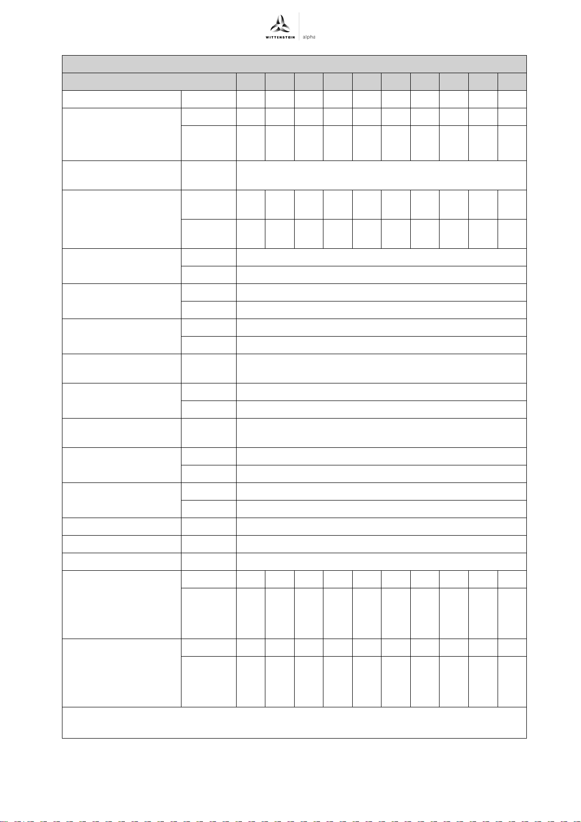
Appendix TK+ ATEX
Technical specifications for TK+ 050, 2-stage
Ratio 12 16 20 25 28 35 40 50 70 100
Max. drive speed n
1Max
Average no-load
running torque T
n
=3000 rpm and 20°C
1
gearhead temperature)
012
(At
a
Max. torsional backlash
j
t
Torsional rigidity C
Max. axial force F
Max. radial force F
t12
2AMax
2RMax
Max. tilting moment
M
2KMax
Life L
Calculation see
h
"Technical Basics"
rpm
4500 4500 4500 4500 4500 4500 4500 4500 4500 4500
Nm 1.7 1.1 0.8 0.6 0.6 0.5 0.5 0.4 0.4 0.4
in.lb 15.0 9.7 7.1 5.3 5.3 4.4 4.4 3.5 3.5 3.5
arcmin ≤ 4
Nm/
40 40 40 40 40 40 40 46 44 42
arcmin
in.lb/
356 356 356 356 356 356 356 405 387 376
arcmin
b
N 6900
lbf 1553
b
N 6600
lbf 1485
Nm 1180
in.lb 10443
h See chapter 7.1.4 "Replacing the gearhead"
Weight incl. standard
adapter plate m
Noise level L
n
=3000 rpm w/o load)
1
PA ;
(At
Max. permissible
housing temperature
kg 26
lbm 57
dB(A) ≤ 68
°C +90
F 194
Ambient temperature °C 0 to +40
F 32 to 104
Paint Blue RAL 5002
Direction of rotation Drive and gear output counter-directional
Protection class IP 65
2
Mass moment of inertia
J
1
referring to the drive;
kgcm
-3
10
in.lb.s
4.43 3.97 3.36 3.22 2.82 2.75 2.50 2.47 2.44 2.42
3.92 3.51 2.97 2.85 2.50 2.44 2.21 2.18 2.16 2.14
2
Bore diameters of the
clamping hub: 24 mm
Mass moment of inertia
J
1
referring to the drive;
kgcm
-3
10
in.lb.s
11.3 10.9 10.3 10.1 9.7 9.7 9.4 9.4 9.4 9.3
10.0 9.6 9.1 9.0 8.6 8.6 8.3 8.3 8.3 8.3
2
2
Bore diameters of the
clamping hub: 38 mm
a
No-load running torques diminish during operation
b
Based on the shaft or flange center at the gear output
Tbl-23: TK+ 050, 2-stage: Technical specifications for use in areas with explosion hazards
en-32 2022-D034859 Revision: 02a
Page 35
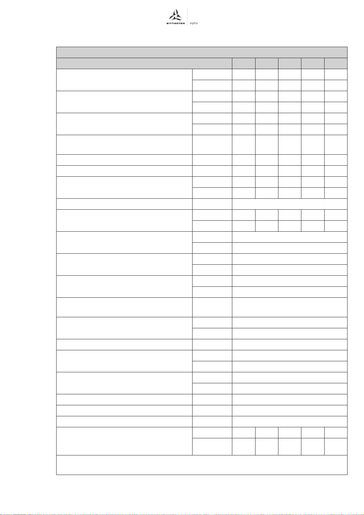
TK+ ATEX Appendix
9.5.5 Technical specifications for TK+ 110 for use in areas with explosion hazards
Technical specifications for TK+ 110, 1-stage
Ratio 3 4 5 7 10
Max. acceleration torque T
2B
(max. 1000 cycles per hour)
Nominal torque at gear output T
(At n
Emergency-stop torque T
1N
)
2Not
2N
(1000 times
possible during the lifespan of the gearhead)
012 ;
1N
2N
(At
Permissible medium drive speed in n
(At T
Max. continuous speed n
Max. drive speed n
2N
)
(At 20% T
1Ncym
1Max
Average no-load running torque T
n
=3000 rpm and 20°C gearhead temperature)
1
Max. torsional backlash j
Torsional rigidity C
Max. axial force F
Max. radial force F
2AMax
2RMax
t12
t
b
b
Nm 400 400 400 350 300
in.lb 3540 3540 3540 3098 2655
Nm 250 250 250 230 220
in.lb 2213 2213 2213 2036 1947
Nm 900 900 900 900 900
in.lb 7965 7965 7965 7965 7965
rpm 900 1100 1200 1100 1100
) rpm 1100 1300 1500 1400 1400
rpm 1300 1700 2200 3000 3000
a
Nm 17.5 14.5 12 18 15
in.lb 155 128 106 159 133
arcmin ≤ 4
Nm/arcmin 76 87 99 97 96
in.lb/arcmin 676 766 874 860 847
N 9900
lbf 2228
N 10250
lbf 2306
Max. tilting moment M
2KMax
Nm 2250
in.lb 19913
Life L
h
Calculation see "Technical Basics"
h See chapter
7.1.4 "Replacing the
gearhead"
Weight incl. standard adapter plate m kg 48
lbm 106
Noise level L
PA
(At n
=3000 rpm w/o load) dB(A) ≤ 68
1
Max. permissible housing temperature °C +90
F 194
Ambient temperature °C 0 to +40
F 32 to 104
Paint Blue RAL 5002
Direction of rotation Drive and gear output counter-directional
Protection class IP 65
Mass moment of inertia J
referring to the drive;
1
10
kgcm
-3
in.lb.s
2
96.5 64.6 50.5 38.2 31.8
2
85.4 57.2 44.7 33.8 28.1
Bore diameters of the clamping hub: 48 mm
a
No-load running torques diminish during operation
b
Based on the shaft or flange center at the gear output
Tbl-24: TK+ 110, 1-stage: Technical specifications for use in areas with explosion hazards
Revision: 02a 2022-D034859 en-33
Page 36

Appendix TK+ ATEX
Technical specifications for TK+ 110, 2-stage
Ratio 12 16 20 25 28 35 40 50 70 100
Max. acceleration
torque T
2B
(max. 1000 cycles per
hour)
Nominal torque at gear
output T
(At n
1N
2N
)
Emergency-stop torque
T
2Not
(1000 times possible
during the lifespan of the
gearhead)
Permissible medium
drive speed in n
1N
(At T2N)
Max. continuous speed
n
1Ncym
(At 20% T2N)
Max. drive speed n
1Max
Average no-load
running torque T
012
(At n1=3000 rpm and
20°C gearhead
temperature)
a
Nm 400 400 400 400 400 400 400 400 350 300
in.lb
3540 3540 3540 3540 3540 3540 3540 3540 3098 2655
Nm 250 250 250 250 250 250 250 250 230 220
in.lb
2213 2213 2213 2213 2213 2213 2213 2213 2036 1947
Nm 900 900 900 900 900 900 900 900 900 900
in.lb
rpm
rpm
rpm
7965 7965 7965 7965 7965 7965 7965 7965 7965 7965
2150 2150 2150 2150 2150 2150 2150 2300 2550 2700
2800 2800 2800 2800 2800 2800 2800 2800 3000 3000
4000 4000 4000 4000 4000 4000 4000 4000 4000 4000
Nm 3.6 2.8 2.2 1.9 1.6 1.4 1.1 1.1 1.1 1.1
in.lb 31.9 24.8 19.5 16.8 14.2 12.4 9.7 9.7 9.7 9.7
Max. torsional backlash
j
t
Torsional rigidity C
Max. axial force F
Max. radial force F
t12
2AMax
2RMax
Max. tilting moment
M
2KMax
Life L
h
Calculation see
"Technical Basics"
Weight incl. standard
adapter plate m
Noise level L
PA
(At n1=3000 rpm w/o
load)
arcmin ≤ 4
Nm/
87 87 87 87 87 87 87 99 97 96
arcmin
in.lb/
766 766 766 766 766 766 766 874 860 847
arcmin
b
N 9900
lbf 2228
b
N 10250
lbf 2306
Nm 2250
in.lb 19913
h See chapter
kg 54
lbm 119
dB(A) ≤ 68
7.1.4 "Replacing the gearhead"
Max. permissible
housing temperature
°C +90
F 194
en-34 2022-D034859 Revision: 02a
Page 37
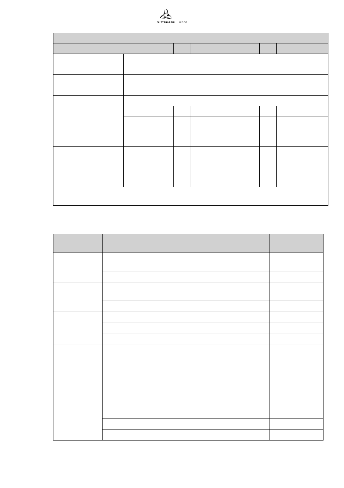
TK+ ATEX Appendix
Technical specifications for TK+ 110, 2-stage
Ratio 12 16 20 25 28 35 40 50 70 100
Ambient temperature °C 0 to +40
F 32 to 104
Paint Blue RAL 5002
Direction of rotation Drive and gear output counter-directional
Protection class IP 65
Mass moment of inertia
J
1
referring to the drive;
Bore diameters of the
clamping hub: 38 mm
Mass moment of inertia
J
1
referring to the drive;
Bore diameters of the
clamping hub: 48 mm
a
No-load running torques diminish during operation
b
Based on the shaft or flange center at the gear output
kgcm
-3
10
in.lb.s
kgcm
-3
10
in.lb.s
2
16.8 14.8 12.9 12.3 11.2 10.9 10.3 10.1 10.0 9.9
14.8 13.1 11.4 10.9 9.9 9.6 9.1 9.0 8.8 8.8
2
2
31.5 29.5 27.6 27.0 25.9 25.6 25.0 24.8 24.7 24.6
27.9 26.1 24.4 23.9 22.9 22.6 22.1 22.0 21.9 21.8
2
Tbl-25: TK+ 110, 2-stage: Technical specifications for use in areas with explosion hazards
9.6 Lubricant quantity Gearhead size
+
TK
004 3, 4, 5, 16, 20, 25, 28,
010 3, 4, 5, 16, 20, 25, 28,
025 3, 4, 16, 20, 28, 40 Tribol 800 100 170
050 3 Tribol 800 100 270
Ratio i Oil type Viscosity class
ISO VG
Filling quantity
[cm³]
Tribol 800 100 50
35, 40, 50
7, 10, 70, 100 Tribol 800 220 60
Tribol 800 100 110
35, 40, 50
7, 10, 70, 100 Tribol 800 220 130
5, 25, 35, 50 Tribol 800 100 190
7, 10, 70, 100 Tribol 800 220 210
4, 16, 20, 28, 40 Tribol 800 100 300
5, 25, 35, 50 Tribol 800 100 330
7, 10, 70, 100 Tribol 800 220 380
110 3 Tribol 800 100 850
4, 5, 16, 20, 25, 28,
Tribol 800 100 1000
35, 40, 50
7, 70 Tribol 800 220 1200
10, 100 Tribol 800 220 1350
Tbl-26: Lubricant quantity
Revision: 02a 2022-D034859 en-35
Page 38
Appendix TK+ ATEX
9.7 Declaration of Conformity
en-36 2022-D034859 Revision: 02a
Page 39
TK+ ATEX Appendix
Revision: 02a 2022-D034859 en-37
Page 40

2022-D016962
:
01
enAC: XXXXXXXX 2022-D016962 Revision: 01
WITTENSTEIN alpha GmbH · Walter-Wittenstein-Straße 1 · 97999 Igersheim · Germany
Tel. +49 7931 493-12900 · [email protected]
WITTENSTEIN - being one with the future
www.wittenstein-alpha.de
 Loading...