

Page 1
simco
Operating Manual
®
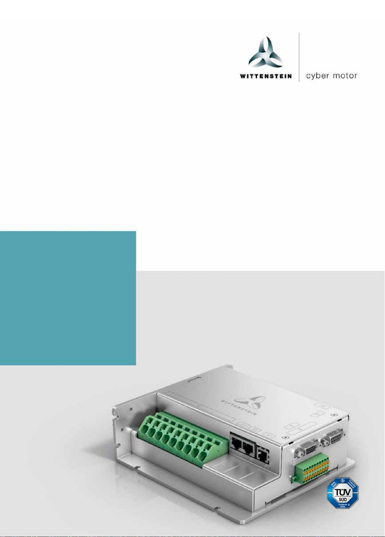
drive SIM2050D
4022-D048047 Revision: 04
Page 2

Page 3
deutsch
english
italiano
deutsch
english
français
italiano
español
Revision
Date
Comment
Chapter
01
02.03.17
New version
All
02
23.03.17
WCM
All
03
05.12.17
Support hotline
STO
10
04
04.06.19
Translation ja
All
Operating Manual simco
®
drive SIM2050
Revision histor y
Risk assessment
SERCOS III
All
Technical support
Should you have any questions about customer service or repair, please contact our Customer
Service department.
Customer Service department WITTENSTEIN cyber motor GmbH
Walter-Wittenstein-Str. 1
D-97999 Igersheim, Germany
Tel.: +49 (0) 79 31 / 493-15900
Fax: +49 (0) 79 31 / 493-10903
E-mail: service@wittenstein-cyber-motor.de
Should you have any questions about installation, startup, or optimization, please contact our
support hotline.
WITTENSTEIN cyber motor GmbH support hotline
Tel.: +49 (0) 79 31 / 493-14800
Copyright
© WITTEN STEIN cyber motor GmbH 2019
This documentation is copyright protected.
WITTENSTEIN cyber motor GmbH reserves all the rights to photo-mechanical reproduction,
copying, and the distribution by special processes (such as computers, file media, data
networks), even in parts.
Subject to technical and content changes without notice.
Revision: 04 4022-D048047 en-1
日本語
Page 4

simco
®
drive SIM2050 Operating Manual
Contents
1 About this manual 3
1.1 Signal words 3
1.2 Safety symbols 3
1.3 Design of the safety instructions 4
1.4 Information symbols 4
2 Safety 4
2.1 Approvals 4
2.1.1 CE conformity 4
2.1.2 Safety conformity (STO) in
accordance with the Machinery
Directive 5
2.2 EC directives 5
2.3 Startup 5
2.4 Hazards 5
2.5 Personnel 5
2.6 Intended use 6
2.7 Improper use 6
2.8 Risks 6
2.8.1 Prohibited movements 6
2.8.2 Dangerous temperatures 6
3 Description of the simco® drive 7
3.1 Identification of the drive
amplifier 7
3.2 Code 7
3.3 Electrical data 8
3.4 Description of the simco® drive
series 8
3.4.1 Integrated safety 8
3.4.2 Digital control 8
3.4.3 Inputs and outputs 8
3.4.4 Ambient conditions 9
3.5 Requirements for cables and
wiring 9
3.6 STO safety function 9
4 Transport and storage 9
4.1 Transport 9
4.2 Packaging 9
4.3 Storage 9
5 Mechanical installation 10
5.1 Safety instructions 10
5.2 Dimensions 11
5.3 Mounting options 11
5.4 Installation space 12
5.5 Environmental conditi o ns for
vibration/shock 12
5.6 Mounting position 12
5.7 Heat dissipation 12
5.7.1 SIM2050D flex cooling unit 13
5.8 Ventilation/cooling 13
6 Electrical installat i on 14
6.1 Safety instructions 14
6.2 Requirements for pow er adapter s
and supply voltage 14
6.3 Overview of plug connections 15
6.4 Connection diagram 16
6.5 Grounding and functio nal
ground 17
6.6 Shield connection 17
6.7 Electrical interfaces 17
6.7.1 X1/X2: Fieldbus interface
CANopen 17
6.7.2 X1/X2: Fieldbus interface
PROFINET / E th e rNet/IP,
PROFINET, EtherNet/IP,
SERCOS III 18
6.7.3 X3: RS232 18
6.7.4 X4: Encoder 19
6.7.5 X5: Resolver 20
6.7.6 X6: Digital I/O 20
6.7.7 X7: Motor connection 21
6.7.8 X8: Power supply 22
6.8 Fuses 22
6.9 Motor circuit protection 23
7 Startup and operation 23
7.1 Safety instructions 23
7.2 Startup software 23
7.2.1 Displays on the device 24
7.2.2 LED P1 status drive
7.2.3 LED P2 drive fault state 25
7.2.4 LED P3 fieldbus status 25
7.2.5 LED P4 fieldbus fault state 26
8 Maintenance and disposal 28
8.1 Maintenance 28
8.2 Repairs 28
8.3 Disposal 28
9 Attachment 28
9.1 Tightening torques 28
10 Instructions for STO safety
function 28
10.1 Installation space 29
10.2 STO wiring 29
10.3 Important information for STO 29
10.4 Intended use of STO 29
10.5 Improper use of STO 29
10.6 Technical specifications and STO
pin assignment 30
10.7 STO pin assignment 30
10.8 Function description 31
10.8.1 Safe operation sequence 32
10.9 Functional check 32
24
en-2 4022- D048047 Revision: 04
Page 5
Operating Manual simco® drive SIM2050
deutsch
english
italiano
deutsch
english
français
italiano
español
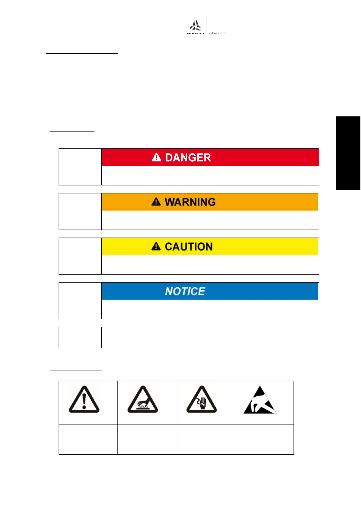
This signal word indicates an imminent danger that will cause
serious injuries or even death.
This signal word indicates a potential hazard that could cause
serious injuries and even death.
This signal word indicates a potential hazard that could cause
minor or serious injuries.
This signal word indicates a potential hazard that could lead to
material damage.
A note without a signal word indicates application hints or
especially important information for handling the product.
General
Hot surface
Electric
Component
discharge
1 About this manual
This manual contains necessary information to safely use the simco® drive amplifier,
hereinafter referred to as the drive amplifier.
The operator must ensure that this operating manual is read through by all persons assigned
to install, operate, or maintain the drive amplifier, and that they fully comprehend them.
Store these instructions within reach of the drive amplifier.
Pass the safety instructions on to other persons as well.
The original manual was created in German; all other language versions are translations of
these instructions.
1.1 Signal words
The following signal words are used to indicate possible hazards, prohibitions, and important
information:
1.2 Safety symbols
hazard
Revision: 04 4022-D048047 en-3
voltage
sensitive to
electrostatic
日本語
Page 6
simco® drive SIM2050 Operating Manual
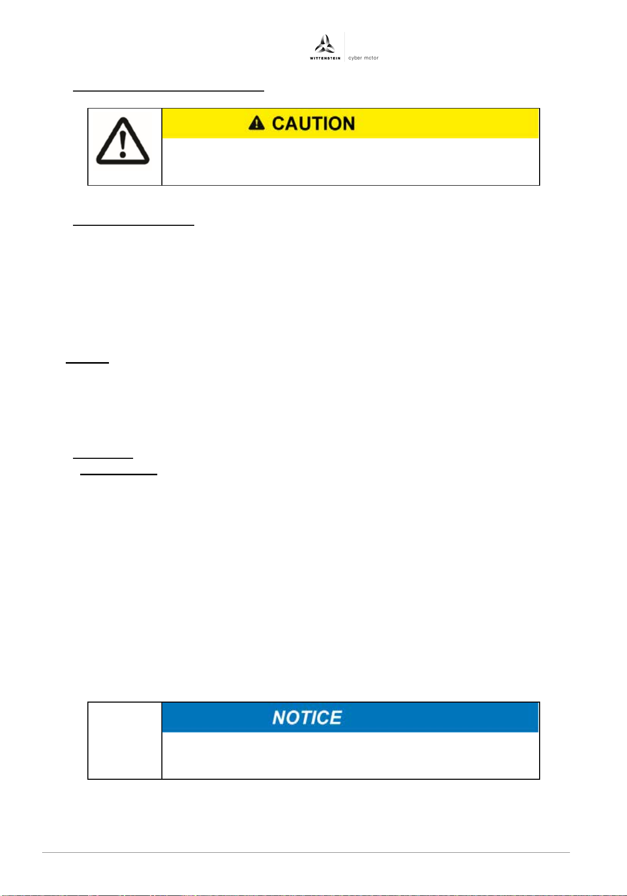
Explanatory text describes the consequences of not complying
• Instructional text describes directly what to do.
• In a residential environment, the drive amplifier may cause radio
as an external EMC filter.
1.3 Design of the safety instructions
with the instructions.
1.4 Information symbols
The following information symbols are used:
• Indicates an action to be performed
Ü Indicates the results of an action
i Provides additional information about the action
2 Safety
This operating manual, especially the safety instructions, and the rules and regulations valid
for the operating site must be observed by all persons working with the drive amplifier.
In addition to the safety instructions in this manual, also observe any (legal and otherwise)
applicable environmental and accident prevention rules and regulations (e.g. personal
safety equipment).
2.1 Approvals
2.1.1 CE conformity
The drive amplifier was tested in authorized testing laboratories in accordance with the
requirements of this documentation. Deviations and nonconformity with requirements in this
documentation mean that the drive amplifier may not fulfill statutory requirements under certain
circumstances.
The drive amplifier is in conformity with the following directives:
− Machinery Directive (2006/42/EC)
− Electromagnetic Compatibility (EMC) (2014/30/EU)
− RoHS Directive (2011/65/EU)
In terms of interference immunity, the drive amplifier fulfills the requirement for the category
"second environment" (industrial environment).
In the area of interference emission, the drive amplifier fulfills the requirements for category C3.
interference, necessitating interference suppression measures such
en-4 4022- D048047 Revision: 04
Page 7
Operating Manual simco® drive SIM2050
deutsch
english
italiano
deutsch
english
français
italiano
español
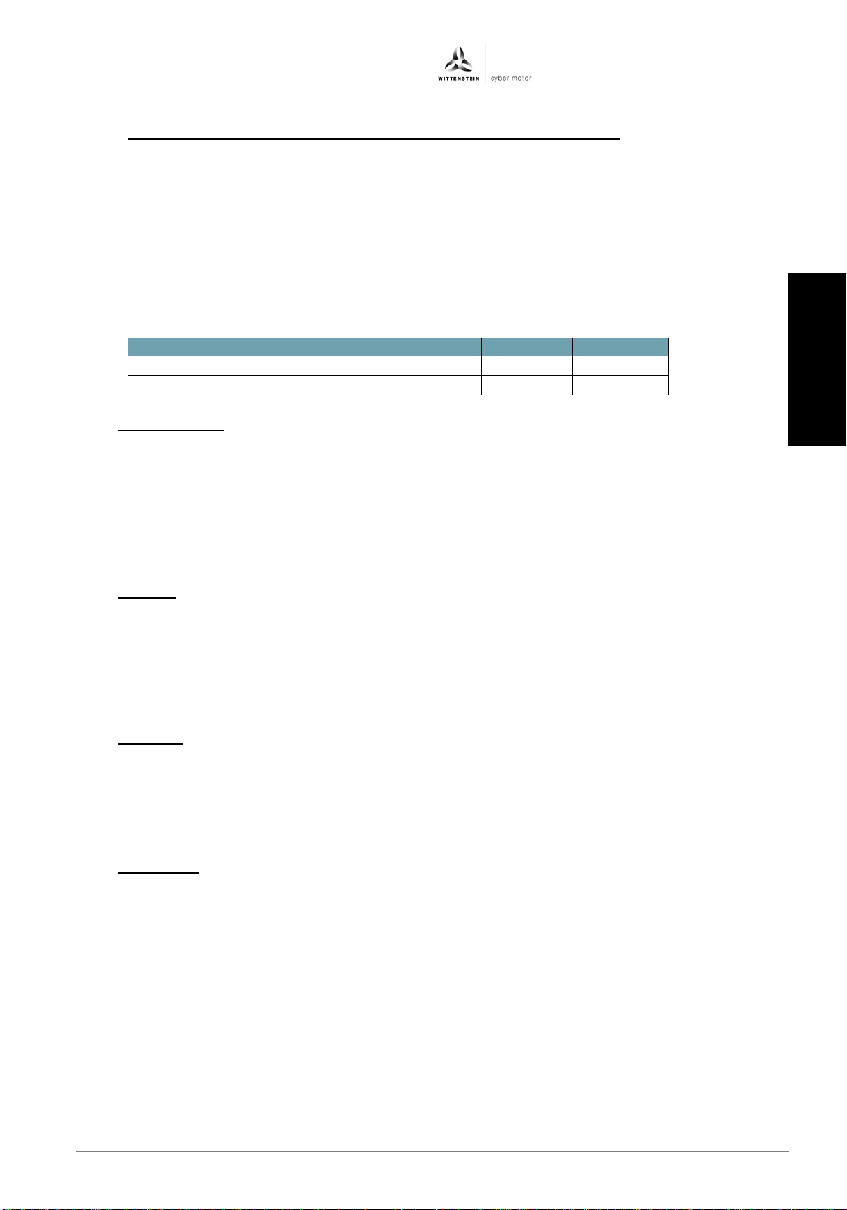
Operating mode
EN 13849-1
EN 61508
PFHD [1/h]
Single-channel
PLd, cat 3
SIL 2
1E-10
Two-channel
PLe, cat 4
SIL 3
1E-10
2.1.2 Safety conformity (STO) in accordance with the Machinery Directive
The drive amplifier provides a two-channel, functionally safe STO function (Safe Torque Off). The
function disables the firing pulses of the power transistors so that the drive can be switched safely
to torque OFF.
The circuit design has been tested and subsequently assessed by TÜV Süd. According to that
assessment, the circuit design used for the "Safe Torque Off" safety function in the simco drive
serie s of drive amplif iers is suitable for meeting the requirements for SIL 3 in accordance with EN
61508 and category 4 PLe in accordance with EN ISO 13849-1:2015.
The subsystems (drive amplifiers) are fully described in terms of safety by the following
characteristics:
2.2 EC directives
The drive amplifier is subjec t to the following EC directive:
− Machinery Directive (2006/42/EC)
− Electromagnetic Compatibility (EMC) (2014/30/EU)
− RoHS Directive (2011/65/EU)
Startup is prohibited within the scope of the EC directives until it has been determined that the
machine/system in which this drive amplifier is installed corresponds to the regulations within
these directives.
2.3 Startup
For installation in machines and systems, start of intended use of the drive amplifier is
prohibited until it has been determined that the machine or system complies with the
provisions of the EC Machinery Directive 2006/42/EC and the EC EMC Directive 2014/30/EU.
For use in residential areas, additional EMC measures are necessary.
It is the responsibility of the manufacturer of the machine or system to ensure that the
threshold values, as stipulated by the EMC regulations, are adhered to.
2.4 Hazards
The drive amplifier has been constructed according to current technological standards and
accepted safety regulations.
i To avoid danger to the operator or damage to the machine, the drive amplifier may be put to
use only for its intended usage (see Chapter 2.6 "
and safe state.
2.5 Personnel
Only qualified technicians who have read and understood this manual may carry out work on
the drive amplifier.
Information on the drive amplifier, in particular the safety instructions, must be accessible to all
persons who work with the drive amplifier.
Qualified technicians are characterized by their education and training in the use of electronic
drive technology. They know the relevant standards and accident prevention regulations for
drive technology and can evaluate its use. Potential hazards are recognized immediately. The
local regulations (ICE, VDE, VGB) are known to the technicians and are taken into account
during their work.
In case of ambiguities and functions that are not described or not sufficiently described in the
Revision: 04 4022-D048047 en-5
documentation, the manufacturer or retailer must be contacted.
Intended use") and in a technically flawless
日本語
Page 8

simco® drive SIM2050 Operating Manual
2.6 Intended use
The drive amplifiers are intended for operation of permanent magnet EC synchronous servo
motors with compatible feedback systems in stationary machines and systems.
Other uses must first be approved by the manufacturer.
Installation of the drive amplifiers is only approved in stationary electrical cabinets or
stationary machine frames. They are used in industrial environments. For use in residential
areas, additional EMC measures are necessary. The user must prepare a hazard analysis
of the final product.
2.7 Improper use
The drive amplifiers are not suitable for operation of motors other than EC synchronous
servo motors or motors with non-compatible feedback systems.
In addition, the following applications are excepted from intended use:
− Life-sustaining medical devices
− Applications in explosive areas
− Use in nuclear plants
− Use in airplanes
2.8 Risks
The manufacturer must strive to reduce residual risks associated with the drive amplifier as
much as possible by taking appropriate action. Nonetheless, known residual risks must be
taken into account for the risk assessment of machines and systems.
2.8.1 Prohibited movements
Prohibited movements can be caused by:
− The failure or shut-down of safety monitoring
− Software fault in associated controllers or bus systems
− Error during parameterization
− Wiring fault
− Limited reaction time of the controller
− Operation outside of the specifications
− Electromagnetic interference, lightning strike
− Component failure
2.8.2 Dangerous temperatures
Dangerous temperatures on the surface of the device can be caused by:
− Faulty installation
− Incorrect installation site
− Faulty electrical protection
− Conductive pollution, condensation
en-6 4022- D048047 Revision: 04
Page 9
Operating Manual simco® drive SIM2050
deutsch
english
italiano
deutsch
english
français
italiano
español
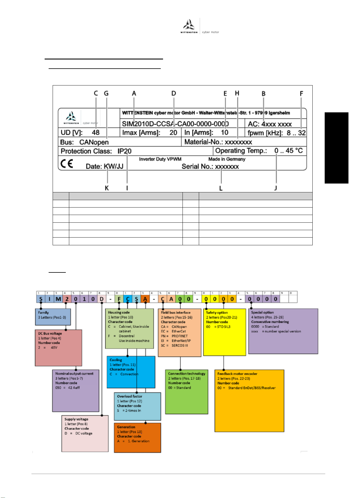
Designation
Designation
A
Code
G
Fieldbus type
B
Article code
H
Material number (customer specific)
C
Intermediate voltage
I
Protection class
D
Maximum output current
J
Permissible ambient temperature
E
Nominal output current
K
Production date
F
PWM frequency of the output stage
L
Serial number
Table 3.1: Identification plate (sample values)
3 Description of the simco® drive
3.1 Identification of the drive amplifier
The identification plate is fitted on the side or the front of the drive amplifier.
3.2 Code
Using the following code, the properties of the drive amplifier can be determined.
Revision: 04 4022-D048047 en-7
日本語
Page 10
simco® drive SIM2050 Operating Manual
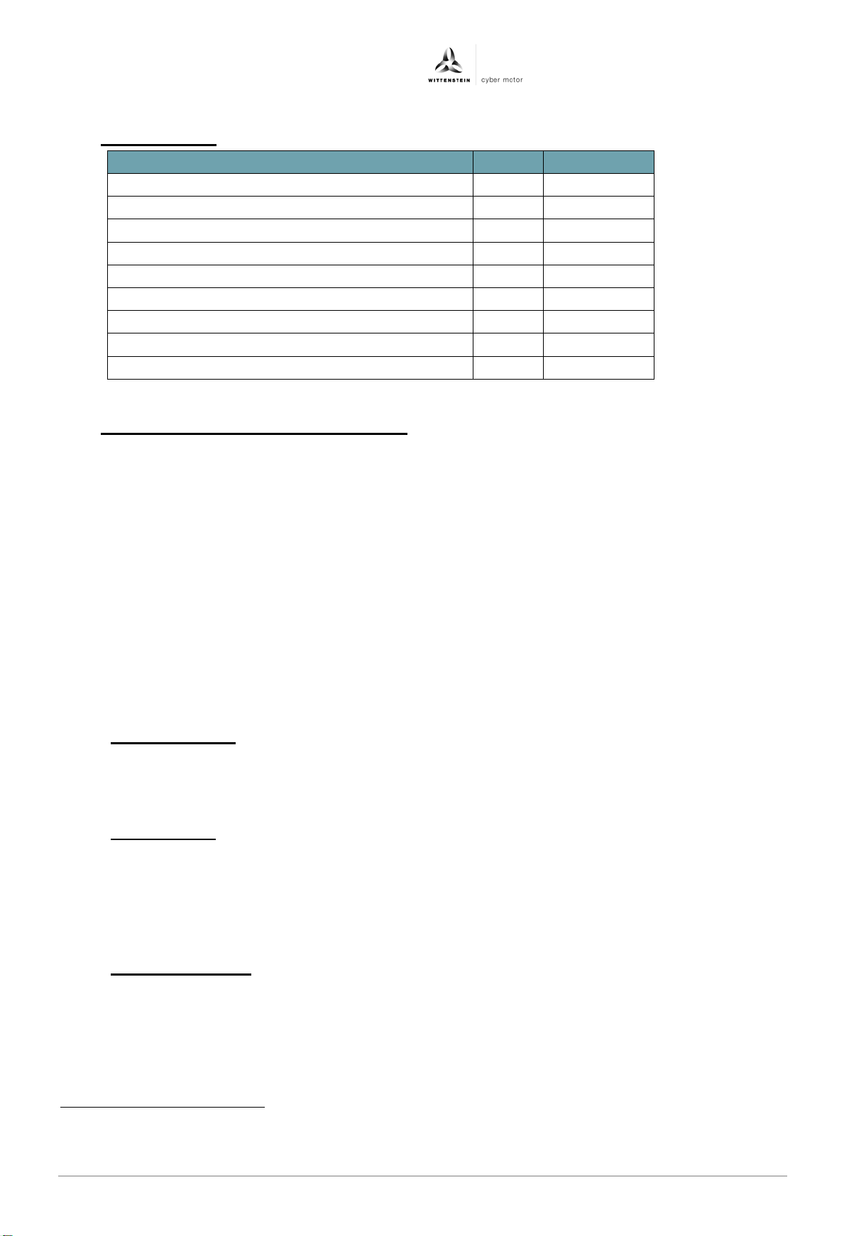
Electrical data
Unit
SIM2050D
Nominal supply voltage, intermediate circuit
V DC
48
Nominal power
W
2500
Intermediate voltage
V DC
12 .. 60
Logic power supply
V DC
12 .. 60
Current consumption of logic supply
mA DC
< 250
Nominal output current of the output stage
Aeff
421
Peak output current of the output stage (for 5s)
Aeff
84
Switching frequency of the output stage
kHz
8 .. 32
Electrical rotary field frequency
Hz
0 .. 1000
3.3 Electrical data
3.4 Description of the simco® drive series
WITTENSTEIN simco® drive is an intelligent drive amplifier series for sine-commutated servo
motors with a continuous power of up to 2000 W and peak output of up to 4000 W.
The different types of housing in the simco
installation.
The housing with protection class IP65 enables decentralized assembly, so that the drive
technology can be integrated modularly and flexibly in the machine structure, reducing wiring.
The drive amplifier with protection class IP20 on the other hand is designed for central
installation in the control cabinet.
Depending on the device version, CANopen according to DS402, EtherCAT with CoE,
PROFINET RT/IRT, Ethernet/IP IO or SERCOS III with FSP Drive is available as a
communication interface.
The intelligence is reflected in the wide range of encoder interfaces, such as ENDAT 2.2, BISS
C or Resolver, high resolution current regulation and event logging with real-time clock.
Intuitive startup and diagnosis is possible using the PC-based, MotionGUI graphic user
interface.
3.4.1 Integrated safety
− Comprehensive diagnostic functions to protect the drive amplifier, such as
overvoltage, overcurrent, short circuit or ground fault.
− Temperature monitoring of the drive amplifier, motor, and optionally the gearbox.
3.4.2 Digital control
− Digital d-q current controller (PI) with a sampling rate of up to 32 kHz
− Digital position and speed controller (PI) with a sampling rate of 8 kHz
− Feed forward control of speed and current possible
− Adjustable pulse width modulation with a clock rate of 8 .. 32 kHz
− Anti-windup structure for all controllers
3.4.3 Inputs and outputs
− 4 programmable galvanically isolated digital inputs, 24 V
− 2 programmable galvanically isolated digital outputs, 24 V (short-circuit proof)
− Output for controlling a 24 V holding brake
®
drive series allow for a high degree of flexibility in
1
In the case of a vertical mounting position, the nominal output current of the output stage is achieved using the
recommended cooling units and a PWM frequency of 8 kHz. The nominal output current may reduce considerably
in the case of other mounting positions or PWM frequencies.
en-8 4022- D048047 Revision: 04
Page 11
Operating Manual simco® drive SIM2050
deutsch
english
italiano
deutsch
english
français
italiano
español
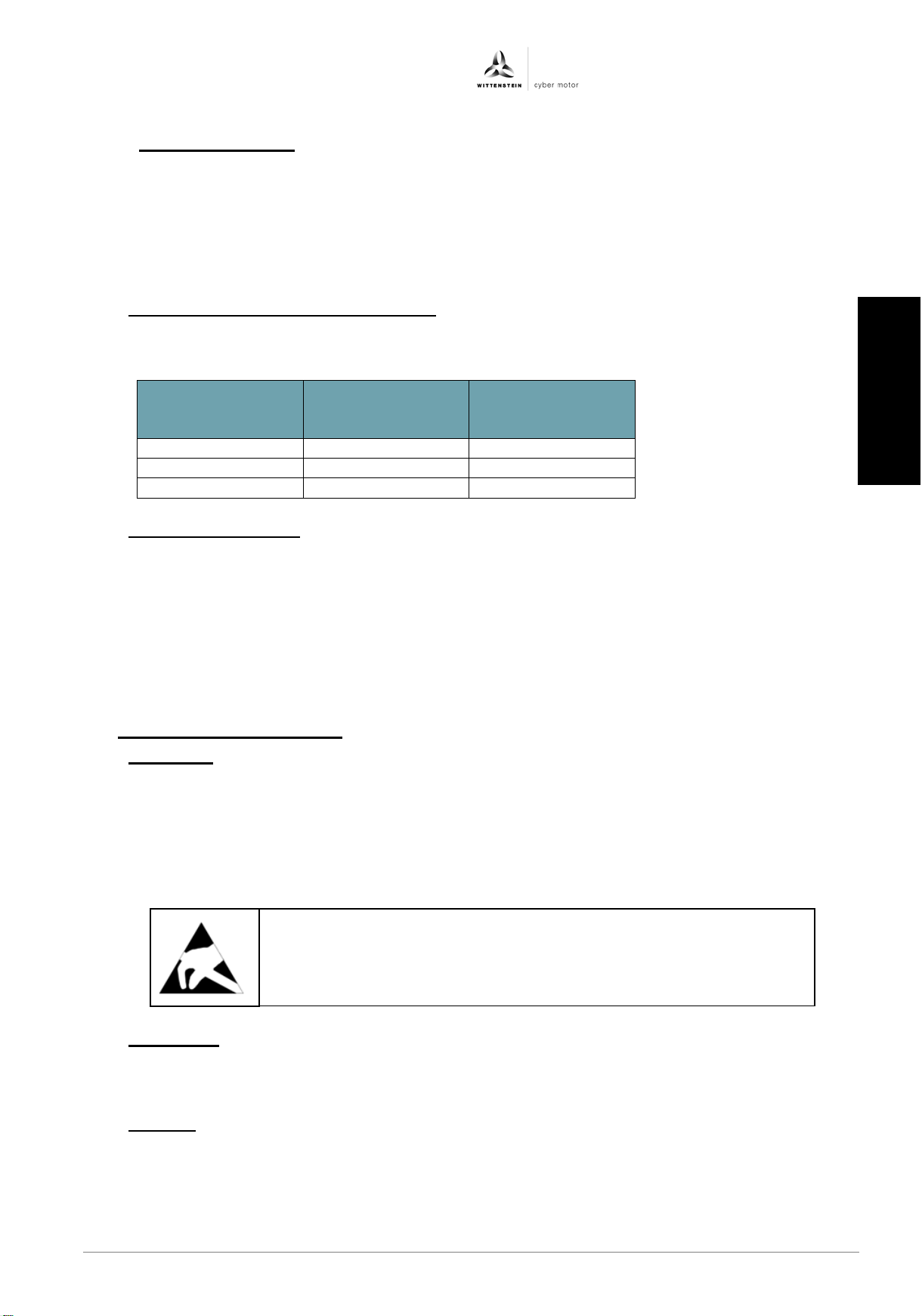
Wire type
Maximum
Capacitance per
Core to shield
Motor wire
20 m
< 150 pF/m
Encoder line
20 m
< 120 pF/m
Resolver line
20 m
< 120 pF/m
The drive amplifier contains components that are sensitive to
•
3.4.4 Ambient conditions
− Ambient temperature during operation: 0 .. 45 °C for nominal data
− Air humidity during operation: Relative humidity < 85%, non-condensing
− Installation altitude: < 1000 m above sea level without affecting performance
− Protection class: IP20 in accordance with EN60529
− Degree of pollution 2 to EN 60204 / EN 50178
3.5 Requirements for cables and wiring
• In general, use high-quality, shielded motor and encoder cables to avoid EMC
problems.
length
3.6 STO sa fety function
The STO safety function (Safe Torque Off) is used for safe torque shutdown and to reliably
protect drives from restarting. The drive amplifier is fitted with a two-channel STO function
as standard in the basic model.
i Instructions for the STO safety function can be found in the appendix (see Chapter 110
"Instructions for STO safety function").
4 Transport and storage
4.1 Transport
− Transportation only in original packaging by qualified personnel
− Avoid hard impacts and vibrations
− Transport temperature: -20 .. 60 °C, max. 20 K/hour fluctuation
− Transport air humidity: Relative humidity max. 95%, non-condensing
− If the packaging is damaged, check the drive amplifier for visible damage.
Contact the responsible shipping company.
unit length
electrostatic charge and can be damaged when handled
improperly.
Ensure proper ESD handling by qualified personnel.
4.2 Packaging
− ESD-compatible box
− Identification: Label attached to the outside of the box
4.3 Storage
− Storage only in ESD-compatible original packaging
− Storage temperature: -20 .. 50 °C, max. 20 K/hour fluctuation
Revision: 04 4022-D048047 en-9
− Air humidity: Relative humidity max. 95%, non-condensing
日本語
Page 12
simco® drive SIM2050 Operating Manual
• Installation may only be performed in a de-energized state!
•
Assembly may only be performed by trained personnel.
5 Mechanical installation
5.1 Safety instructions
• For the mechanical installation, the ESD instructions must be observed.
• The drive amplifier (control cabinet version) must be protected from fog, water and
penetration of metallic dust in the electrical cabinet.
• The drive amplifier must be checked for mechanical damage before installation. Only
install flawless drive amp lifiers.
• During installation in an electrical cabinet, sufficient ventilation must be provided.
• The operation of drive amplifiers exposed to condensation is not permitted.
Systems that are electrically connected must be properly secured so
they cannot be switched back on and warning signs must be put up.
en-10 4022- D048047 Revision: 04
Page 13
Operating Manual simco® drive SIM2050
deutsch
english
italiano
deutsch
english
français
italiano
español
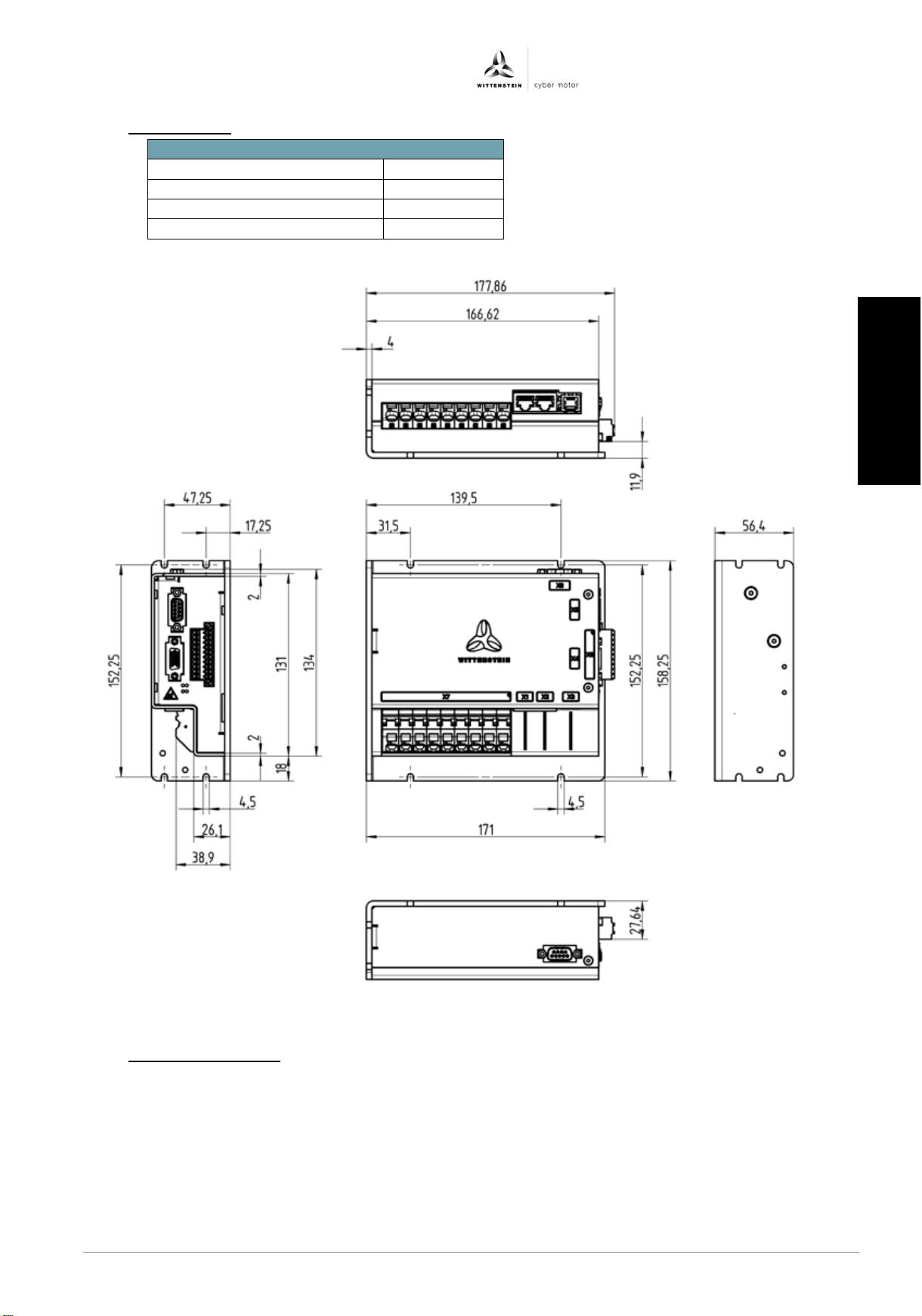
Mechanical specifications
Weight [kg]
1,03
Height without plug mm]
56,4
Width without plug [mm]
171
Depth without plug [mm]
158,25
5.2 Dimensions
5.3 Mounting options
The drive amplifier is mounted to the mounting plate using a screw connection.
Mounting material: 4 cylinder head screws with hexagon socket ISO 4762 - M 4 – 8.8
Required tool: Hexagon socket size 3
Tightening torques see Chapter 9.1 Tightening torques
Revision: 04 4022-D048047 en-11
日本語
Page 14
simco® drive SIM2050 Operating Manual
5.4 Installation space
The drive amplifier is designed for installation in a control cabinet or closed installation space.
5.5 Environmental conditions for vibration/shock
The drive amplifier fulfills the following specifications:
− Vibration according to DIN EN 60068-2-6:2008
o Frequency range 10 Hz – 150 Hz
o Acceleration: 5 g
− Shock according to DIN EN 60068-2-27:2010
o Shock form: Semi-sinusoidal
o Acceleration: 50 g
o Duration of the shock: 11 ms
5.6 Mounting position
The drive amplifier can be installed in any mounting position.
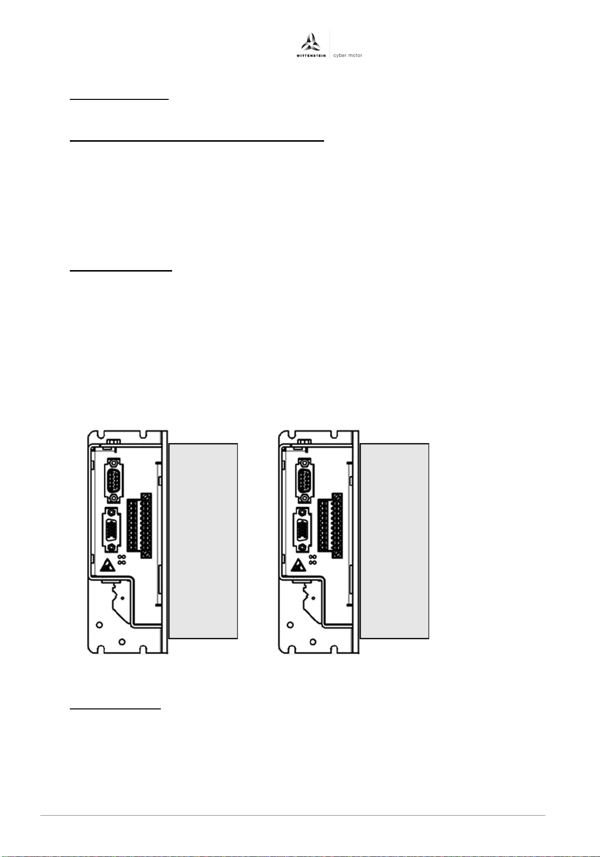
A vertical mounting position with a cooling unit should be used to achieve optimum heat
dissipation.
Performance will decrease if the drive amplifier is not in vertical mounting position, or if the
converter is used with insufficient cooling.
A minimum distance must be ensured if several drive amplifiers are mounted side by side.
Please consult the Application department of Wittenstein cyber motor GmbH regarding the
design of the heat dissipation concept.
5.7 Heat dissipation
The SIM2050D cooling unit should be used for heat dissipation. It is available as an accessory.
Only this cooling unit and a proper mounting position will ensure that the nominal continuous
current of the output stage can be reached and that the device will not overheat.
Other types of heat dissipation can be coordinated with the Application department of
WITTENSTEIN cyber motor GmbH.
en-12 4022- D048047 Revision: 04
Page 15
Operating Manual simco® drive SIM2050
deutsch
english
italiano
deutsch
english
français
italiano
español
• The drive amplifier will be damaged if longer screws are used.
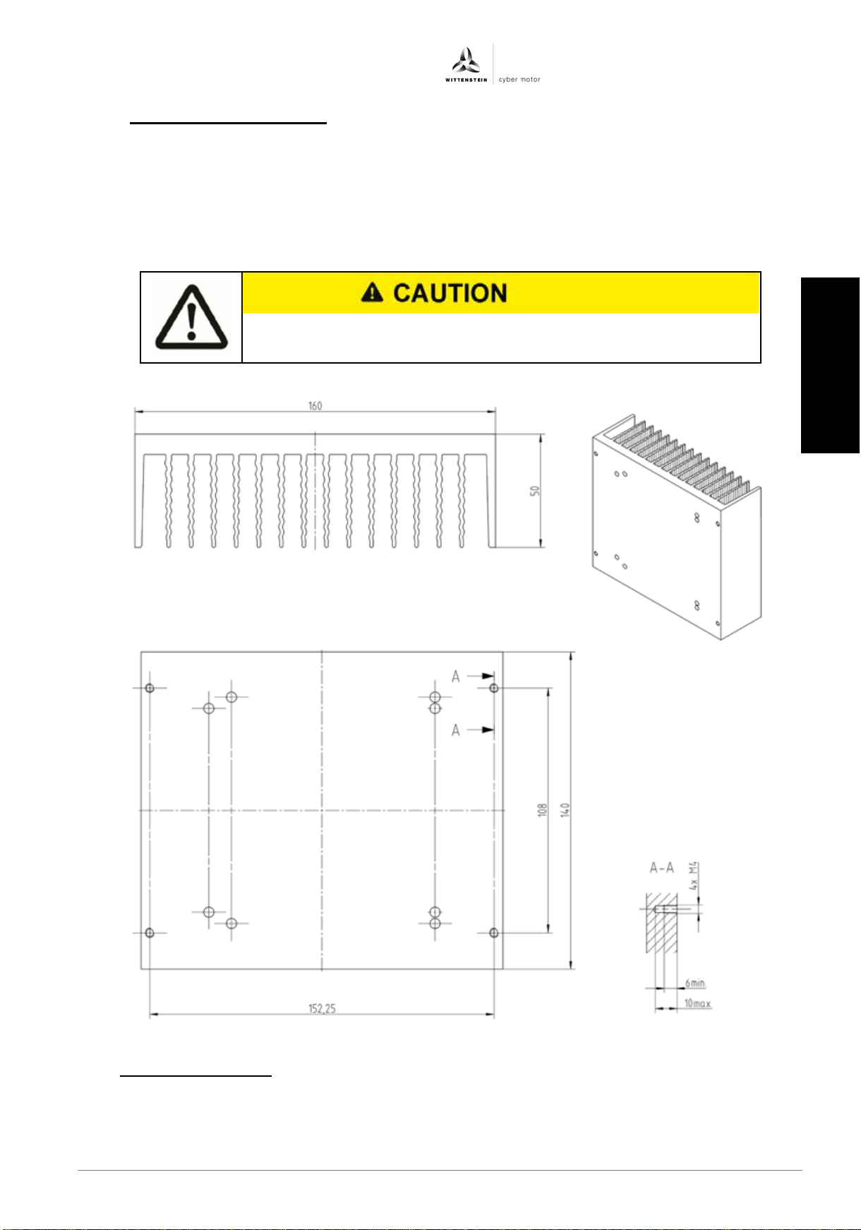
5.7.1 SIM2050D flex cooling unit
Wittenstein material number 50017170-00-0.
The SIM2050D cooling unit consists of the cooling body and the M4x14 screws required for
attachment to the device. Different sets of mounting holes ensure that the the cooling unit can be
rotated by 90° and proper cooling is ensured for different mounting positions of the drive
amplifier.
The drive amplifier can also be mounted with the cooling unit using the four M4 threads (A-A) at
the cooling body.
5.8 Ventilation/cooling
Ensure that there is sufficient forced air circulation in the closed control cabinet (convection).
Revision: 04 4022-D048047 en-13
日本語
Page 16
simco® drive SIM2050 Operating Manual
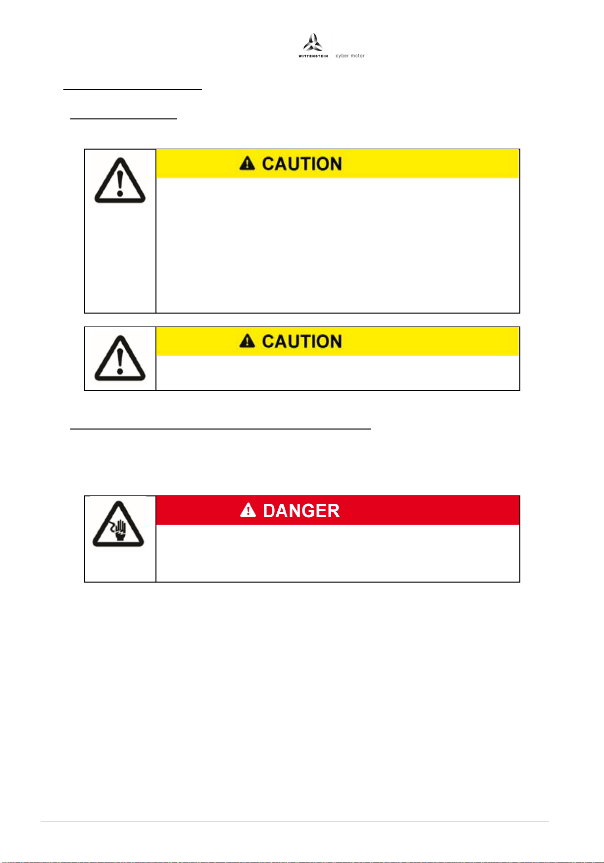
• Systems that are electrically connected must be properly secured so
•
•
•
the cables or the drive amplifier.
• Observe the separate instructions for the STO safety function (see
The use of unsuitable power adapters not in SELV/PELV design can
death.
6 Electrical installation
6.1 Safety instructions
• For the electrical installation, the ESD instructions must be observed.
they cannot be switched back on and warning signs must be put up.
Installation may only be performed by trained personnel.
Before startup, it must be checked that the wiring is correct and is
free of mechanical damage. Only drive amplifiers with wiring in
flawless condition may be put into operation.
Incorrect voltage, reverse polarity and nonconforming wiring can
damage or destroy the drive amplifier.
Excessive or inadequate protection of the power supply can damage
Chapter 3.6 "STO safety function")
6.2 Requirements for pow er a dapters and supply voltage
The drive amplifier's 24 VDC logic supply and 48 VDC power supply must be provided
using power adapters or supply voltage sources with safe extra low voltage in SELV/PELV
design to IEC 60950 / EN 60204. Power adapters or supply voltage sources having only
basic installation are not permissible.
lead to dangerously high voltages in the event of a fault, which
could lead to dangerous electric shocks resulting in injuries or
The 48 VDC power adapter for the power supply must permit feedback up to 60 VDC, as
the drive amplifier can generate a voltage of up to 60 VDC at the power adapter terminals
when operating as a generator. The power adapter should be designed for such operation.
Otherwise suitable action must be taken to prevent feedback.
en-14 4022- D048047 Revision: 04
Page 17
Operating Manual simco® drive SIM2050
deutsch
english
italiano
deutsch
english
français
italiano
español
No.
Function
Connector type on
the device
Connector type on
the cable
X1
Fieldbus interface input
RJ45 socket
RJ45 plug
X2
Fieldbus interface output
RJ45 socket
RJ45 plug
X3
Diagnostic interface RS232
RJ12 socket
RJ12 plug
X4
Encoder interface
D-sub 15-pin female
D-sub 15-pin male
X5
Resolver interface
D-sub 9-pin female
D-sub 9-pin male
X6
Digital inputs/outputs
D-sub 9-pin male
D-sub 9-pin female
X7
Motor connection
X8
Logic supply
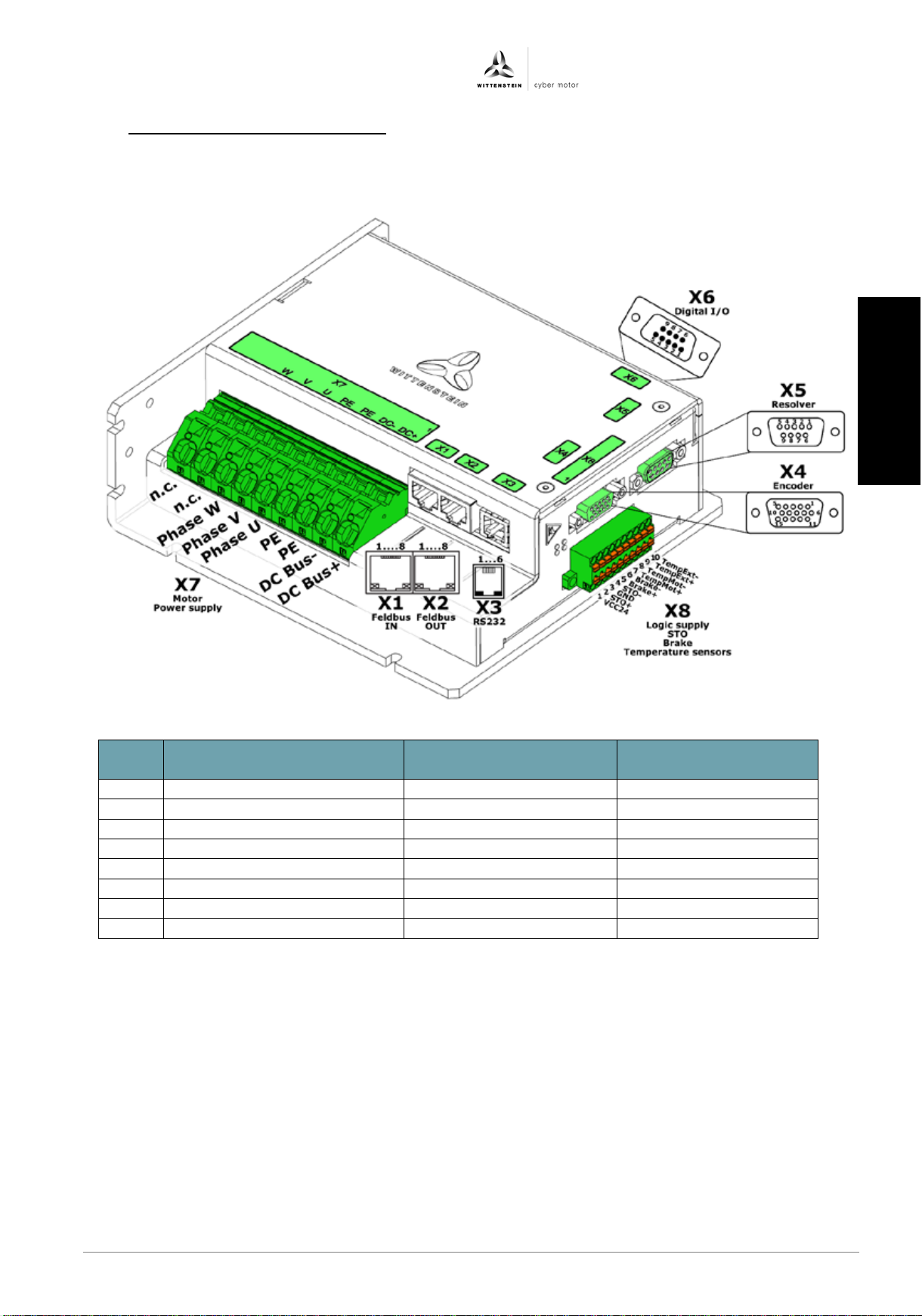
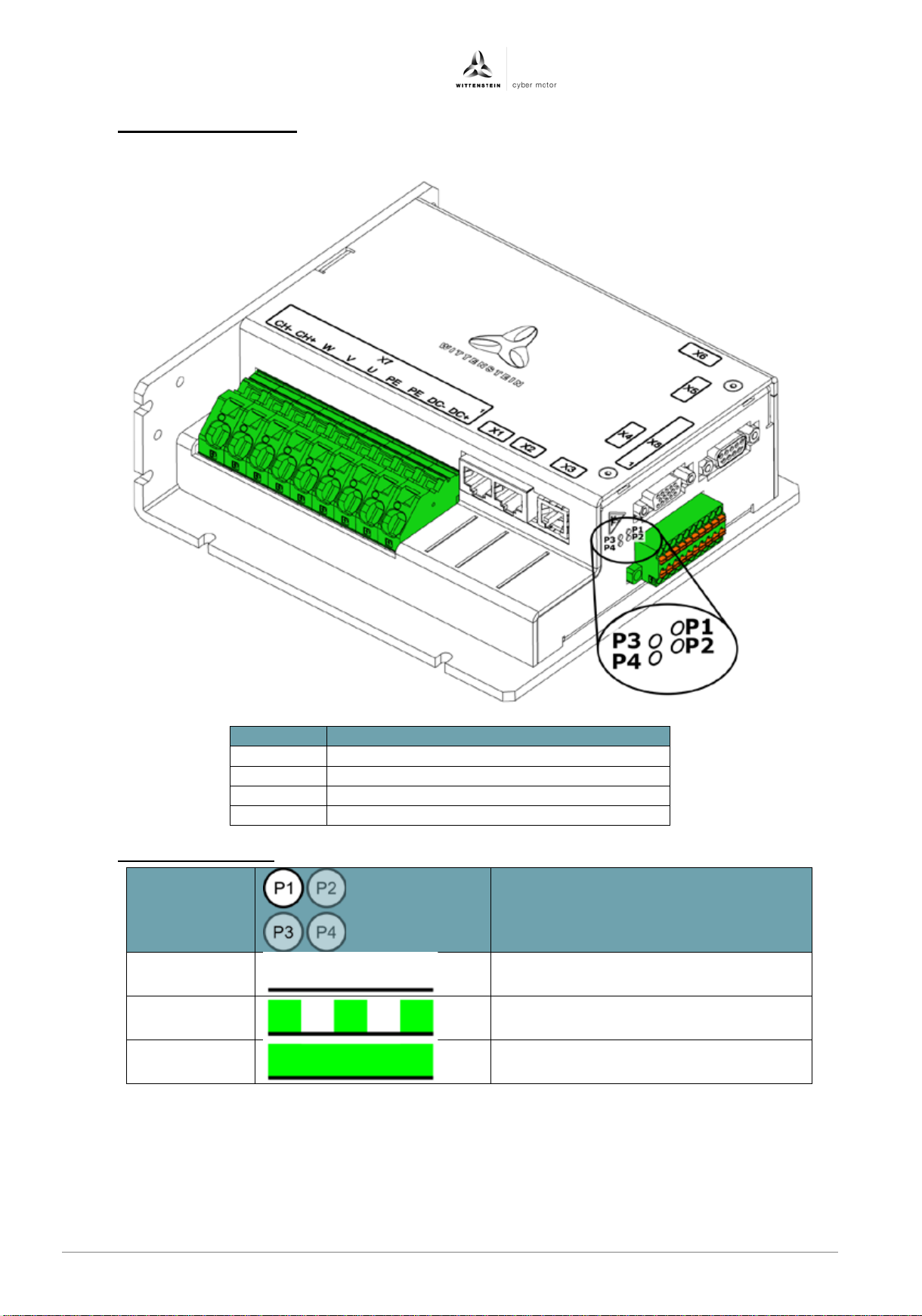
6.3 Overview of plug connections
The following illustration shows the arrangement of the plug connections with associated
label on the drive amplifier:
Revision: 04 4022-D048047 en-15
日本語
Page 18
simco® drive SIM2050 Operating Manual
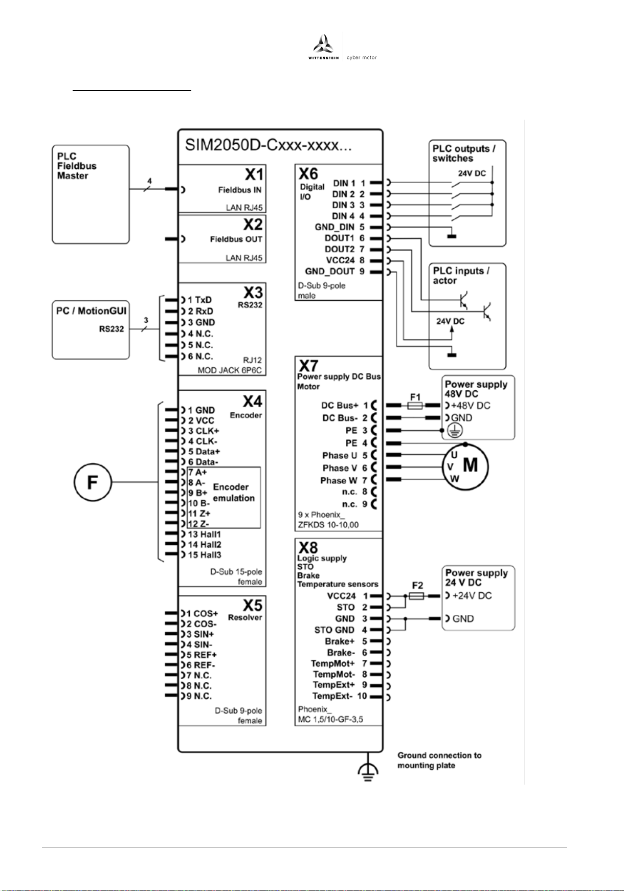
6.4 Connection diagram
The following illustration shows the principal connection diagram of the drive amplifier:
en-16 4022- D048047 Revision: 04
Page 19
Operating Manual simco® drive SIM2050
deutsch
english
italiano
deutsch
english
français
italiano
español
• If the drive amplifier is not sufficiently grounded this may cause radio
electronic systems.
Figure
Pin
no.
Signal
Function
J1
CAN_H
CAN High
J2
CAN_L
CAN Low
J3
CAN_GND
CAN reference
ground
J4
N.C.
J5
N.C.
J6
N.C.
J7
N.C.
J8
N.C.
Plug type on drive amplifier: LAN RJ45
Connection
Properties
Unit
Minimum
value
Nominal
value
Maximum
value
CAN
Baud rate
kbaud
100
500
1000
6.5 Grounding and functional gr ound
In order to maintain conformity with the EMC limit values and ensure the functioning of
the drive amplifier the housing of the drive amplifier must be connected to the control
cabinet or installation space's functional ground with low impedance.
interference, leading to non-conformity with the EC EMC Directive.
This can result in malfunctions in the drive amplifier and other
6.6 Shield connection
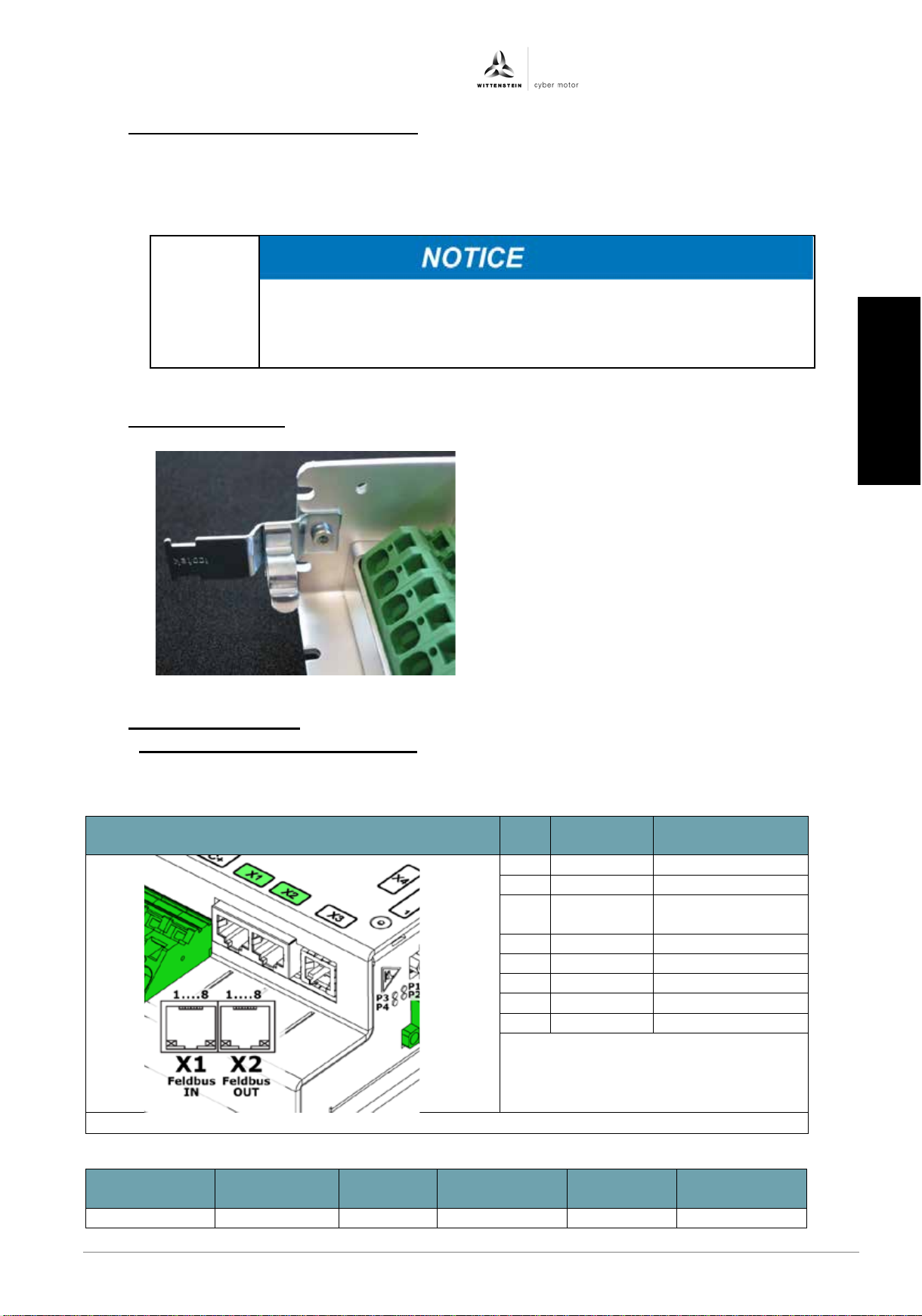
In order to maintain conformity with the EMC
limit values and ensure the functioning of the
drive amplifier the shielding of the motor
cable must be connected to the housing of
the drive amplifier with low impedance and
over a large area.
6.7 Electrical interfaces
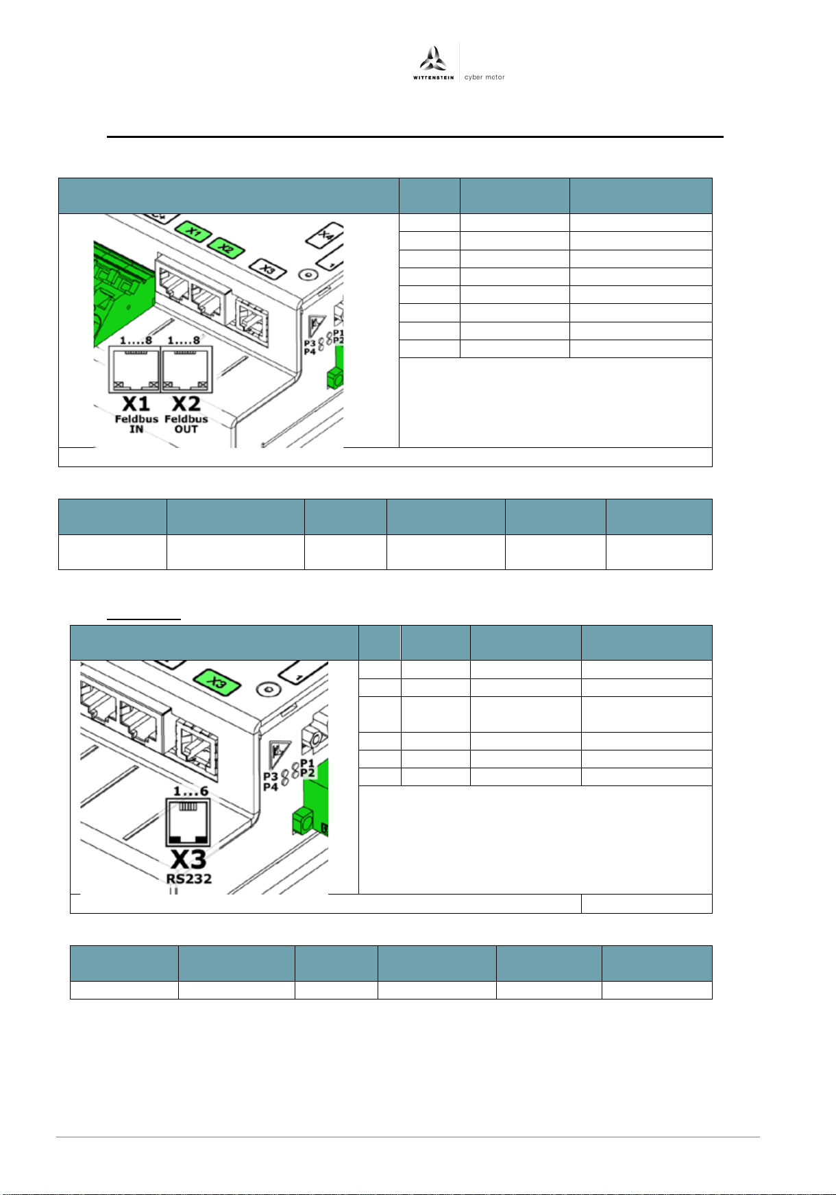
6.7.1 X1/X2: Fieldbus interface CANopen
− The CAN reference ground is identical with the logic reference ground.
− The CAN signals are galvanically isolated from the power of the drive amplifier.
This may be done using an LFZ/SKL
12-16 EMC shield clamp from Icotek, for
example.
Revision: 04 4022-D048047 en-17
日本語
Page 20
simco® drive SIM2050 Operating Manual
Figure
Pin
no.
Signal
name
Function
J1
RD+
Receive Data +
J2
RD-
Receive Data -
J3
TD+
Trans mit Data +
J4
N.C.
J5
N.C.
J6
TD-
Trans mit Data -
J7
N.C.
J8
N.C.
Plug type on drive amplifier: LAN RJ45
Connection
Properties
Unit
Minimum
value
Nominal
value
Maximum
value
RD / TD
Transmission
speed
MBit/s
100
Figure
Pin
no.
Signal
Function
Input/
output
1
TxD
Transmit Data
Output
2
RxD
Receive Data
Input
3
GND
Reference
ground
4
N.C.
5
N.C.
6
N.C.
Plug type on drive amplifier: MOD JACK – MJLS 6P6C
Connection
Properties
Unit
Minimum
value
Nominal
value
Maximum
value
TxD / RxD
Baud rate
baud
115200
6.7.2 X1/X2: Fieldbus interface PROFINET / EtherNet/IP, PROFINET, EtherNet/IP, SERCOS III
− The signals are galvanically isolated from the logic and power of the drive.
6.7.3 X3: RS232
en-18 4022- D048047 Revision: 04
Page 21
Operating Manual simco® drive SIM2050
deutsch
english
italiano
deutsch
english
français
italiano
español
Figure
Pin
no.
Signal
name
Function
Input/output
1
GND
Reference ground
Output
2
VCC
Encoder power
supply
Output
3
CLOCK+
Clock output
Output
4
CLOCK-
Clock output inverted
Output
5
DATA+
Data channel
Input
6
DATA-
Data channel inverted
Input
7
A+
Encoder emulation
A+
Output
8
A-
Encoder emulation A-
Output
9
B+
Encoder emulation
B+
Output
10
B-
Encoder emulation B-
Output
11
Z+
Encoder emulation
Z+
Output
12
Z-
Encoder emulation Z-
Output
13
Hall U
Hall sensor phase U
Input
14
Hall V
Hall sensor phase V
Input
15
Hall W
Hall sensor phase W
Input
Plug type on drive amplifier: D-sub 15-pin female
Connection
Properties
Unit
Minimum
value
Nominal
value
Maximum
value
VCC
Output voltage
V DC
4,5 5 5,5
Output current
mA DC
250
A+, A-, B+,
B-, Z+, Z-
Output voltage
V DC
5
Output current
mA DC
42
Output resistance
Ohm
120
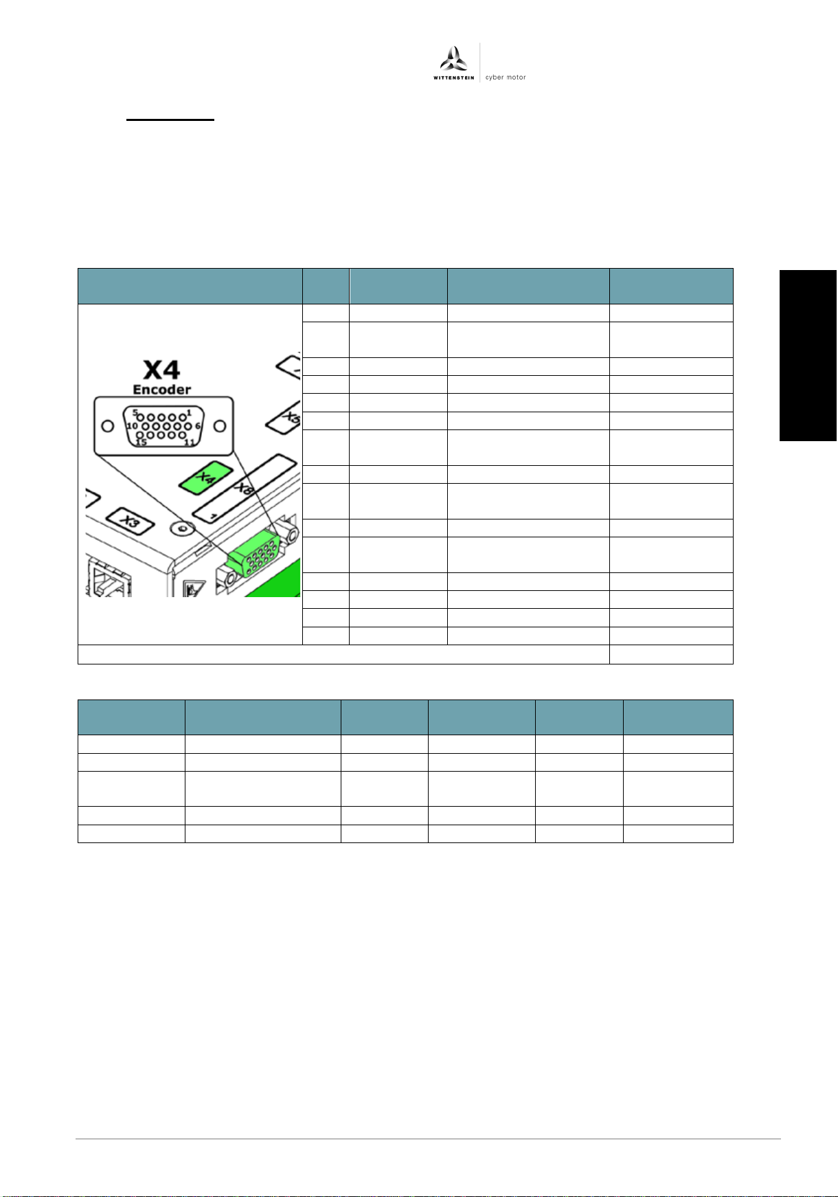
6.7.4 X4: Encoder
• The plug may only be inserted when the drive amplifier is in a de-energized state.
− Via the encoder interface X4, fully digital encoder systems with the protocols EnDat
2.2 and BISS C can be evaluated.
− The encoder interface has a 5 V power supply, secured with a self-resetting fuse, with
a max. current rating of 250 mA.
− Encoder emulation is also available via encoder interface X4.
日本語
Revision: 04 4022-D048047 en-19
Page 22
simco® drive SIM2050 Operating Manual
Figure
Pin
no.
Signal name
Function
Input/output
1
COS+
Cosine trace
S1
Input
2
COS-
Cosine trace
S3
Input
3
SIN+
Sine trace S2
Input
4
SIN-
Sine trace S4
Input
5
REF+
Reference
trace R1
Output
6
REF-
Reference
trace R2
Output
7
N.C.
8
N.C.
9
N.C.
Plug type on drive amplifier: D-sub 9-pin female
Connection
Properties
Unit
Minimum
value
Nominal
value
Maximum
value
Reference
trace
Excitation frequency
kHz
10
Output voltage
Vpk
4 5 5,5
Output current
mA
30
Sine/cosine
Input resistance
kOhm
100
Input voltage
Vpk
2,5
5
Resolution
Bit
10
12
14
Figure
Pin
no.
Signal
Function
Input/outp
ut
1
DIN1
Digital input 1
Input
2
DIN2
Digital input 2
Input
3
DIN3
Digital input 3
Input
4
DIN4
Digital input 4
Input
5
GND
Reference ground
6 DOUT1
Digital output 1
Output
7
DOUT2
Digital output 2
Output
8
VCC24
Digital output
supply
Input
9
GND
Reference ground
Plug type on drive amplifier: D-sub 9-pin male
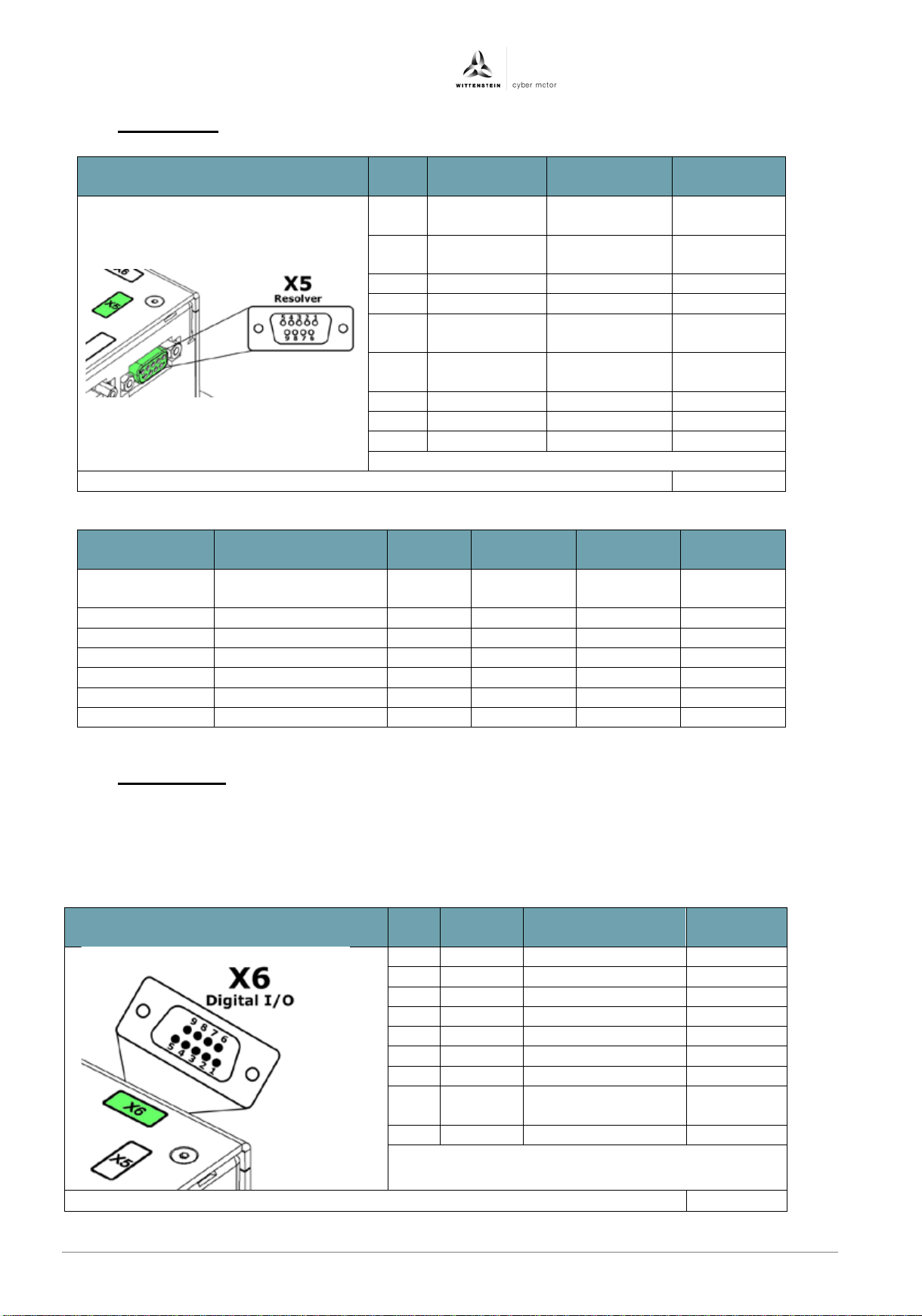
6.7.5 X5: Resolver
6.7.6 X6: Digital I/ O
• An external power supply most be connected to supply the digital outputs.
− The digital outputs are galvanically isolated from the logic and power of the drive
amplifier.
− The digital outputs are short-circuit proof.
en-20 4022- D048047 Revision: 04
Page 23
Operating Manual simco® drive SIM2050
deutsch
english
italiano
deutsch
english
français
italiano
español
Connection
Properties
Unit
Minimum
value
Nominal
value
Maximum
value
DINx
Input voltage
V DC
20
24
28
Input current
mA DC 3 4
5
Input resistance
kOhm 5,6
Sample time
msec
1
GND
Reference ground
DOUTx
Output voltage
V DC
18
24
26
Output current
mA DC
40
Output resistance
kOhm 1 1,5
2
Refresh rate
Hz
1
VCC24
Voltage
V DC
20
24
28
Current
mA DC
80
GND
Figure
Termi
nal
Signal
name
Function
Input/
output
1
DCBus+
Intermediate
voltage +
Input
2
DCBus-
Intermediate
voltage -
Input
3
PE
Earth conductor
4
PE
Earth conductor
5 PHASE_U
Motor phase U
Output
6
PHASE_V
Motor phase V
Output
7
PHASE_W
Motor phase W
Output
8
N.C.
9
N.C.
Terminal on device: 9x Phoenix ZFKDS 10-10.00
Stripping length: 12 mm
Connection
Properties
Unit
Minimum
value
Nominal value
Maximum
value
PHASE_x
Current
Aeff 42
100
DCBus+/-
Voltage
V DC
12
48
60
Current
A DC 50
122
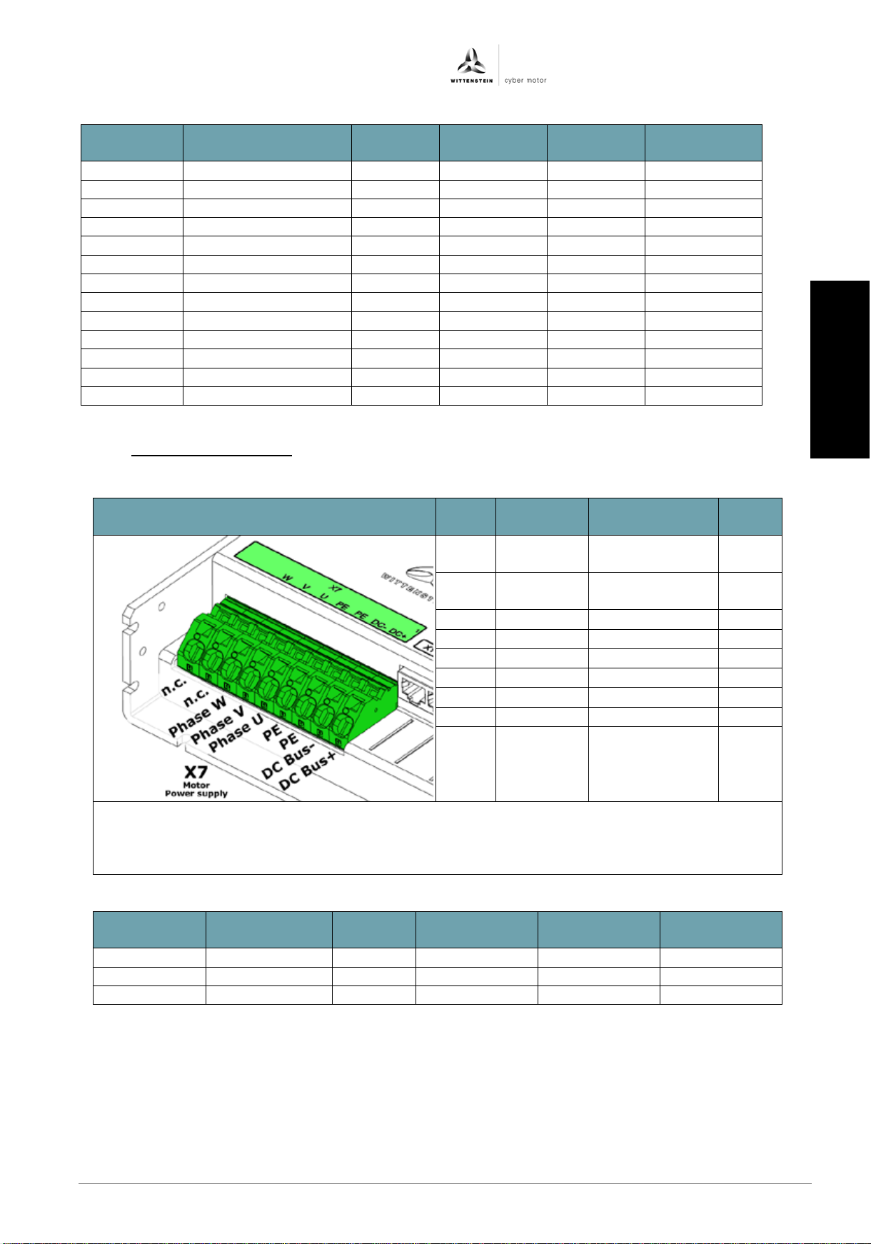
6.7.7 X7: Motor connection
− The intermediate voltage DCBus - (pin 2) is not connected to the housing.
Usable wire types: Flexible wires with/without wire end ferrules, rigid wires
Permissible wire cross-section: 0.2 – 16 mm² (with wire end ferrules 0.25 to 10 mm²)
Revision: 04 4022-D048047 en-21
日本語
Page 24
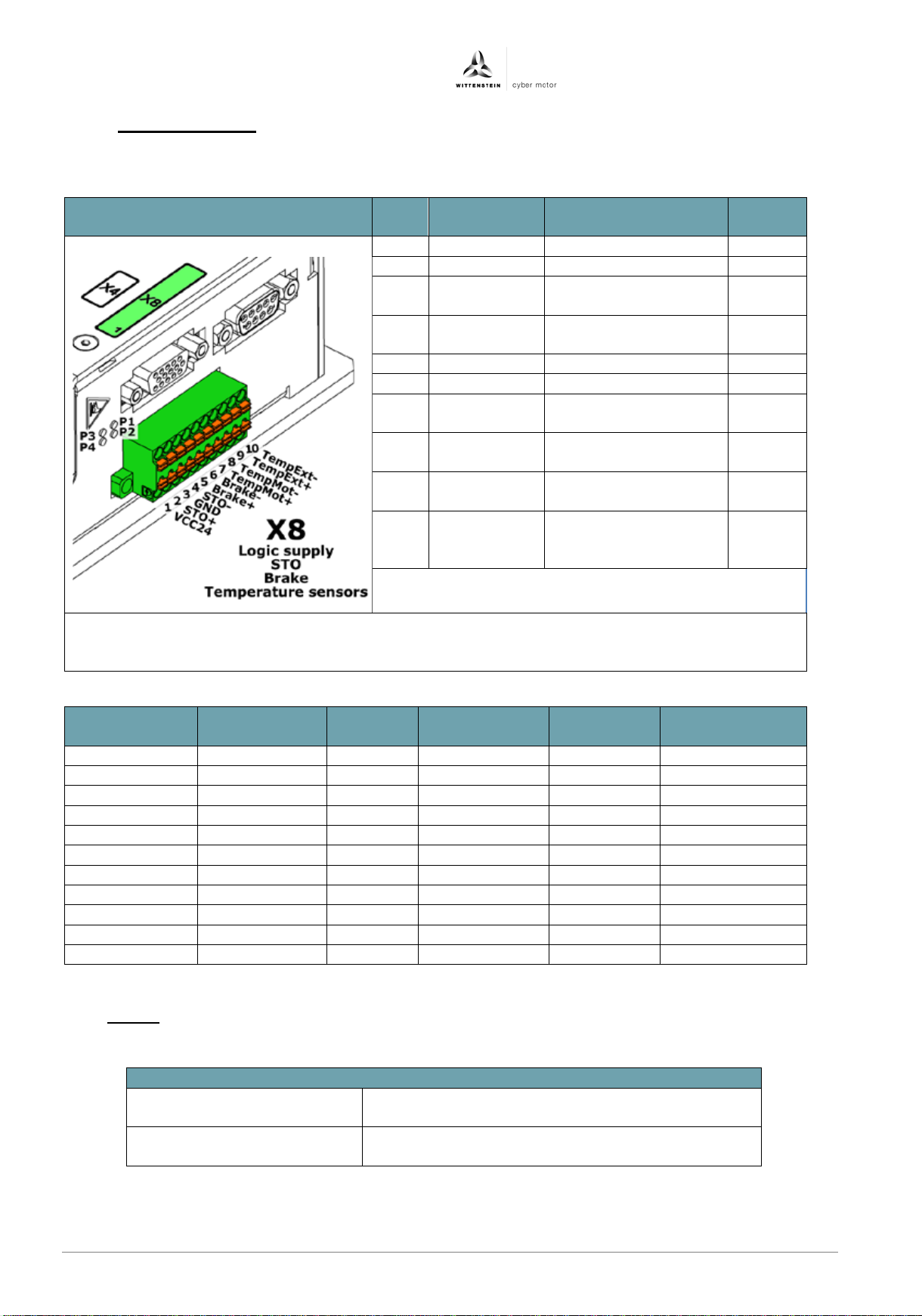
simco® drive SIM2050 Operating Manual
Figure
Pin
no.
Signal name
Function
Input/
output
1
VCC24
Logic supply +24 VDC
Input
2
STO
Safe Torque off input
Input
3
GND
Logic reference
ground
Input
4
STO GND
STO
reference ground
Input
5
BRAKE+
Holding brake +
Output
6
BRAKE-
Holding brake -
Output
7
TempMot+
Motor temperature
sensor +
Input
8
TempMot-
Motor temperature
sensor -
Input
9
TempExt+
External temperature
sensor +
Input
10
TempExt-
External
sensor -
Input
Plug type on cable: TFMC 1.5/10-STF-3.5
Stripping length: 10 mm
Connection
Properties
Unit
Minimum
value
Nominal
value
Maximum
value
VCC24
Voltage
V DC
12
24
60
Current @ 12V
mA DC
500
Current @ 24V
mA DC
220
Current @ 60V
mA DC
100
STO
Voltage
V DC
12
24
60
Current
mA DC
120
BRAKE+/-
Voltage
V DC 24
Current
A DC
1,3
Fuses
Logic supply (F2)
X8 (pin 1 + 2)
Fuse or similar with max. 4 AT
Power supply (F1)
X7 (pin 1)
Fuse or similar with max. 50 AT
6.7.8 X8: Power supply
− The logic supply is galvanically isolated from the intermediate voltage.
− The safety input STO is galvanically isolated from the intermediate voltage.
Temperature-
Permissible wire cross-section: 0.25 .. 1.5 mm²
6.8 Fuses
• The power supplies are to be secured with the fuses specified in the table:
en-22 4022- D048047 Revision: 04
Page 25
Operating Manual simco® drive SIM2050
deutsch
english
italiano
deutsch
english
français
italiano
español
• The housing temperature on the drive amplifier can reach 80 °C
•
before touching the drive amplifier.
• Before startup, the machine manufacturer must prepare a risk
property damage.
• Only technicians with extensive experience with electrical and
amplifier.
• Incorrect parameterization can cause uncontrolled movements.
do not completely understand.
6.9 Motor circuit protection
Circuit breaker hardware to protect the motor is not required as the motor is protected from
overloading by an I²t function in the software and by an optional motor temperature sensor.
7 Startup and operati on
7.1 Safety instructions
For secure application of the drive amplifier, the following regulations must be observed:
− Connection and operating instructions
− Local regulations
− EC regulations and the EC Machinery Directive
7.2 Startup s o ftware
For parameterization and startup of the drive, the startup software motion gui is available as
well as an interactive, html-based help.
The st artup sof tware motion gui is used to change and save the operating parameters of the
drive amplifier. The connected drive amplifiers can be put into operation with the help of
software.
In the html-based help, all parameters and the function of the drive amplifier are described.
during operation.
Wait until the housing temperature has cooled down to 40 °C
assessment for the machine and take appropriate measures so
that unforeseen movements cannot lead to personal injury or
electronic systems and drive technology may start up the drive
Revision: 04 4022-D048047 en-23
For this reason, never change parameters whose meaning you
日本語
Page 26
simco® drive SIM2050 Operating Manual
LED
Function
P1
Status of the drive (green)
P2
Fault state of the drive (red)
P3
Status of the fieldbus (green)
P4
Fault state of the fieldbus (red)
Status LED
Meaning
Off
Drive amplifier has no power supply or
Flashes
Drive amplifier is in functional state
Green
Drive amplifier is in functional state
7.2.1 Displays on the device
Four multicolor LEDs (P1-P4) are available on the drive amplifier for status and fault
messages.
7.2.2 LED P1 status drive
green
is defe ctive
and output stage disabled
and output stage enabled
en-24 4022- D048047 Revision: 04
Page 27
Operating Manual simco® drive SIM2050
deutsch
english
italiano
deutsch
english
français
italiano
español
Status LED
Meaning
Off
Drive amplifier is in c o nforming state
Flashes
Drive amplifier is in fault state, output
Status LED
Meaning
Off
Drive amplifier has no power supply or
Flashes
The CAN node is in the status PRE-
Green
The CAN node is in the status
Status LED
Meaning
Off
Drive amplifier is in the status INIT
Flashes green
The drive amplifier is in the status
Lights up
The drive amplifier is in the status
Lights up
The drive amplifier is in the status
Flashes
(rapidly)
Drive amplifier is in the status
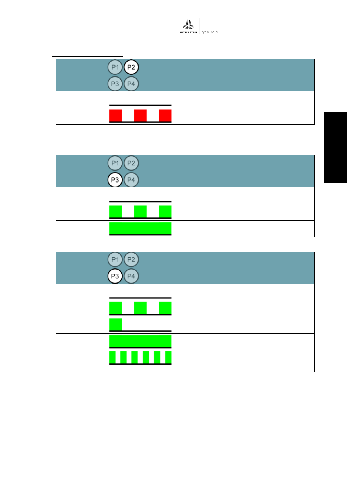
7.2.3 LED P2 drive fault state
red
7.2.4 LED P3 fieldbus status
CANopen:
green
EtherCAT:
stage disabled
is defe ctive
OPERATIONAL
OPERATIONAL
(slowly)
green once
green
green
Revision: 04 4022-D048047 en-25
PRE-OPERATIONAL
SAFE-OPERATIONAL
OPERATIONAL
BOOTSTRAP
日本語
Page 28
simco® drive SIM2050 Operating Manual
Status
Meaning
Off
Profinet interface not ready
Green
Profinet interface is ready
Status
Meaning
Off
Drive amplifier has no power
not ready.
Flashes
The Ethernet IP interface is
connection.
Green
The drive has not established
connection.
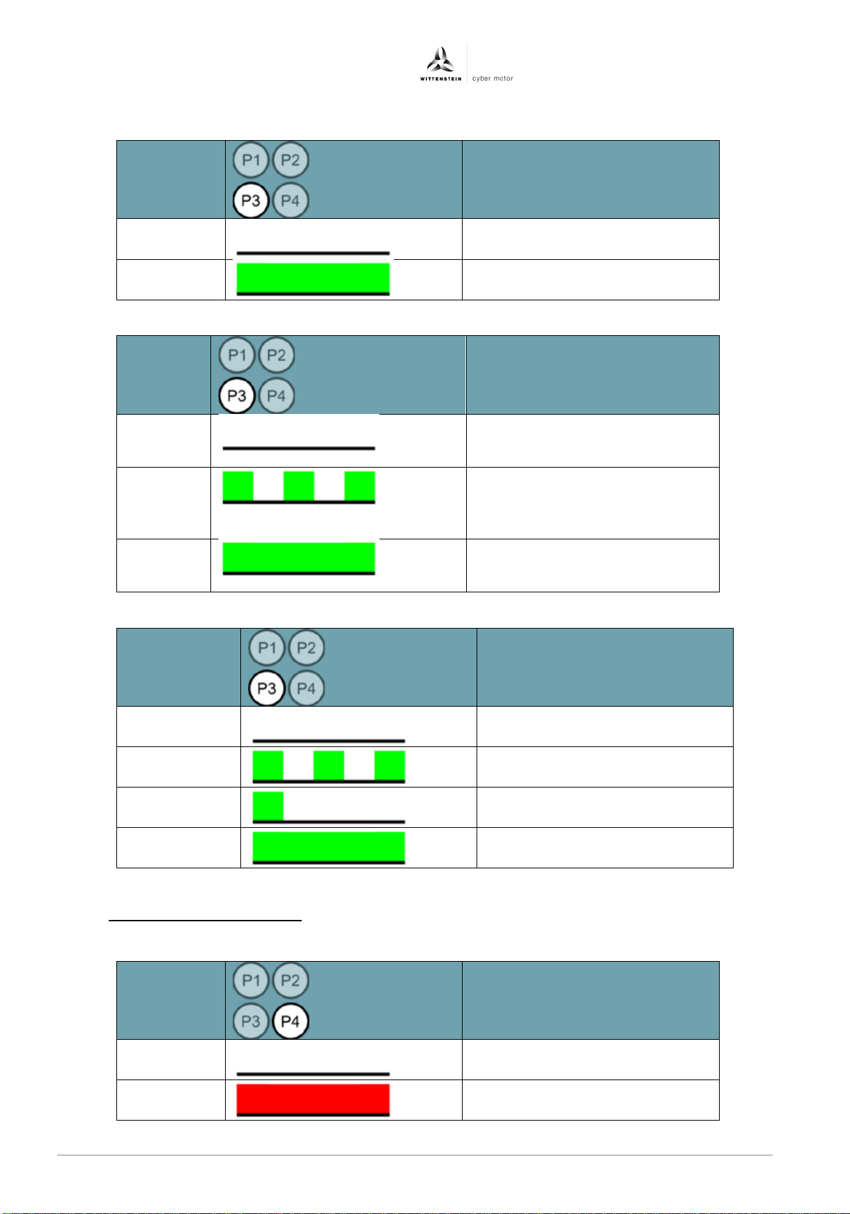
Status LED
Meaning
Flashes
green
Lights up
The drive amplifier is in the
Lights up
green
Status
Meaning
Off
The CAN node is ready for
Red
The CAN node is in fault state
PROFINET:
LED
Ethernet/IP:
LED
green
SERCOS III:
Off
green once
supply or Ethernet IP interface
ready for communication but
does not have an active
an active Ethernet IP I/O
No Sercos communication
Secos communication is being
established
status SAFE-OPERATIONAL
7.2.5 LED P4 fieldbus fault state
CANopen:
LED
en-26 4022- D048047 Revision: 04
Sercos phase 4 reached
operation
Page 29
Operating Manual simco® drive SIM2050
deutsch
english
italiano
deutsch
english
français
italiano
español
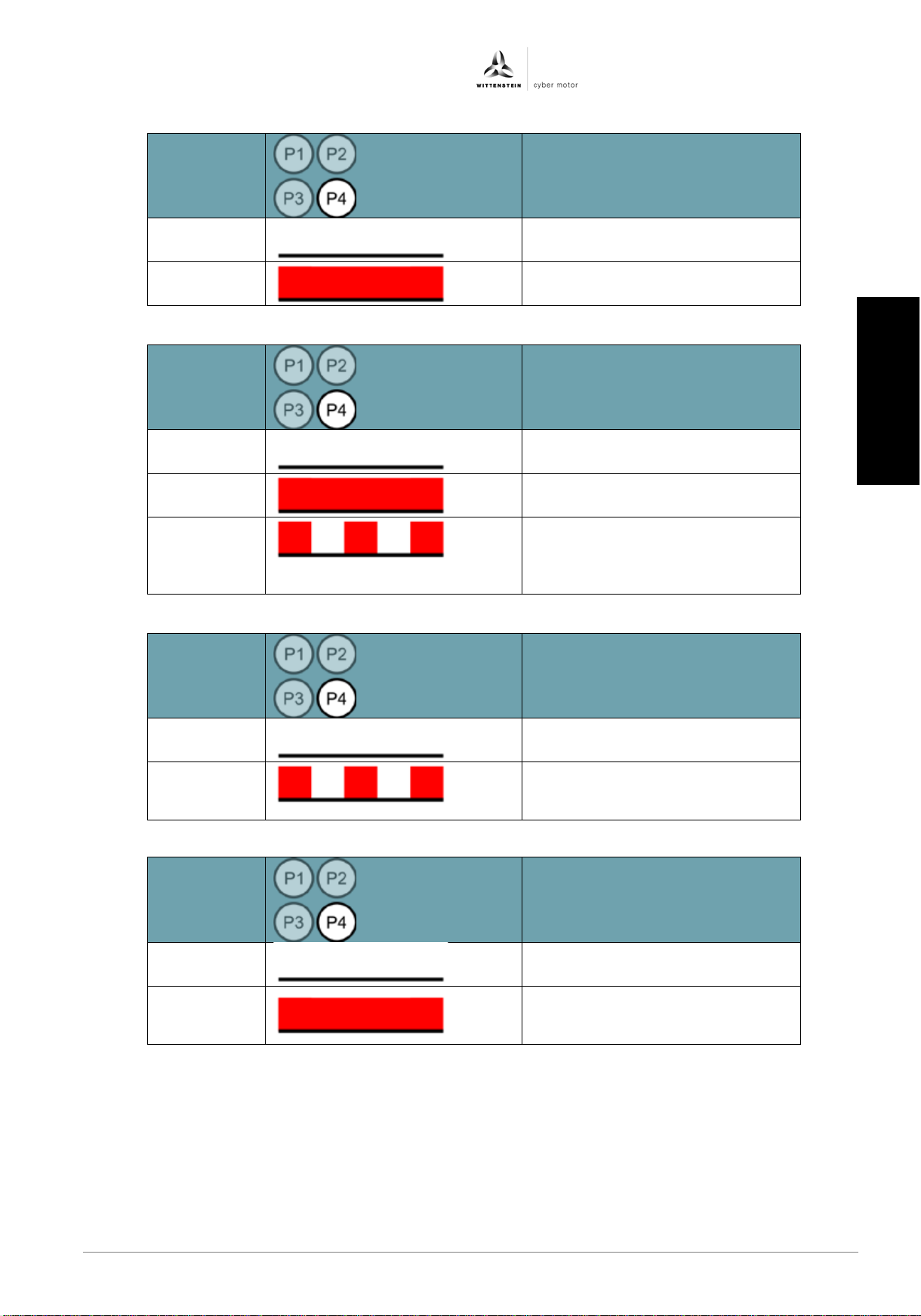
Status
Meaning
Off
The bus is ready for operation
Red
The bus is in fault state
Status
Meaning
Off
There is communication with a
Red
No connection available
Flashes
Connection available however
controller
Status
Meaning
Off
There is communication with an
Flashes
Connection timeout.
been interrupted.
Status
Meaning
Sercos communication error or
established
EtherCAT:
LED
PROFINET:
LED
Profinet controller
red
Ethernet/IP:
LED
red
SERCOS III:
LED
Off
there is no active
communication with an I/O
Ethernet IP controller.
A previously active connection has
The bus is ready for operation
Red
Revision: 04 4022-D048047 en-27
Sercos communication not yet
日本語
Page 30
simco® drive SIM2050 Operating Manual
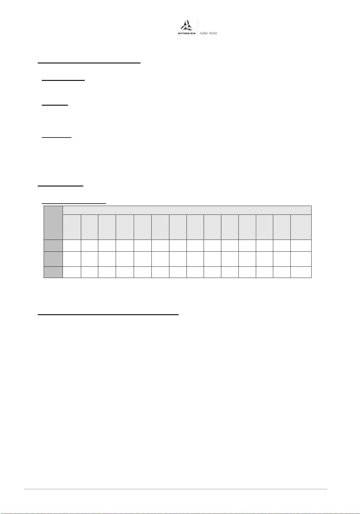
Property
Tightening torque [Nm] for threads...
Table 9.1
8 Maintenance and disposal
8.1 Maintenance
The drive amplifiers are maintenance free. Opening the drive amplifier voids the warranty.
8.2 Repairs
The drive amplifier may only be repaired by the manufacturer. Opening the drive amplifiers
voids the warranty and safety according to the specified standards is no longer ensured.
8.3 Disposal
In accordance with WEEE-2002/96/EC directive, we take back old equipment for proper
disposal as long as the transport costs are paid by the sender.
9 Attachment
9.1 Tightening torques
class
M 3
8.8 1,28 1,96 2,9 5,75 9,9 24 48 83 132 200 275 390 530 675
10.9 1,8 2,75 4,1 8,1 14 34 67 117 185 285 390 550 745 950
12.9 2,15 3,3 4,95 9,7 16,5 40 81 140 220 340 470 660 890 1140
M 4
M 3.5
M 5
M 6
M 8
10 Instructions for STO safety function
The STO safety function (Safe Torque Off) is used for safe torque shutdown and to reliably
protect drives from restarting. The drive amplifier is fitted with a two-channel STO function
as standard in the basic model.
Advantages of the STO safety function:
− Intermediate circuit and main circuit can remain active
− No contact wear because only control voltages are switched on and off
− Less wiring required
− Single-channel or two-channel control possible
− SIL 2 or SIL 3 systems possible
The STO safety function equates to stop category 0 (uncontrolled stoppage) defined by EN
60204-1. The STO safety function of the server amplifier can be triggered by external safety
relays or by an external safety control with safe outputs.
The circuit design has been tested and subsequently assessed by TÜV. According to that
assessment, the circuit design used for the "Safe Torque Off" safety function in the simco
drive series of drive amplifiers is suitable for meeting the requirements for SIL 3 in
accordance with EN 61508 and category 4 PLe in accordance with EN ISO 13849-1:2015.
M 10
M 12
M 14
M 16
M 18
M 20
M 22
M 24
en-28 4022- D048047 Revision: 04
Page 31
Operating Manual simco® drive SIM2050
deutsch
english
italiano
deutsch
english
français
italiano
español
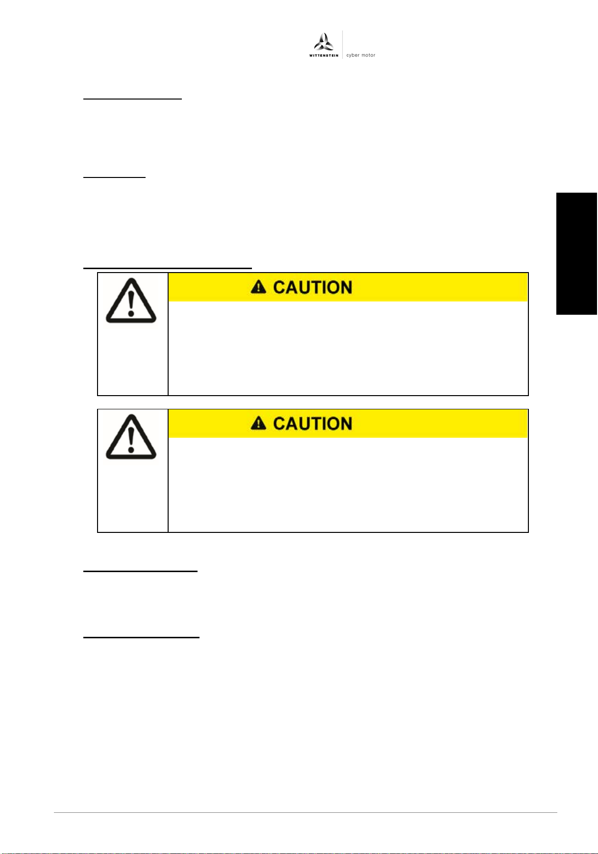
If the STO function is actuated during operation, the drive will coast
•
function must be triggered with a time delay.
Danger from short-term limited movements when STO function is
•
damage.
10.1 Installation space
A drive amplifier in IP20 design should be installed in a space that will ensure reliable operation
of the drive amplifier.
The installation space must meet the requirements of protection class IP54 at least.
10.2 STO wiring
In the case of single-channel control, if the wiring for the STO signals is situated outside a control
cabinet, it must be routed in a permanent installation and protected from external damage (e.g.
by means of a cable duct or hard conduit). Further instructions for wiring can be found in the
standard DIN EN 60204-1.
10.3 Important information for STO
to a stop in an uncontrolled manner and the drive amplifier reports
the "Error_amp_sto_active" fault. Controlled braking of the drive
will not be possible.
If an application requires controlled braking before the use of STO,
the drive must first be braked under control and then the STO
activated.
Simultaneous breakdown of two power transistors in the output stage
can cause short-term movement up to 180° / pole pair number of the
motor.
Make sure that a limited movement of this kind cannot cause any
10.4 Intended use of STO
The STO function is designed only for functionally safe switching of a drive to torque OFF and to
prevent restarting. In order to achieve functional safety, the wiring of the safety circuit must meet
the safety requirements of EN 60204, EN 12100, EN 61508 and/or EN 13849-1
10.5 Improper use of STO
The STO function must not be used if the drive needs to be stopped for the following reasons:
1. Cleaning, maintenance, or repair work; long interruptions in operation:
In such cases the entire machine or system should be de-energized and secured (at the main
switch).
2. Emergency stop situations:
In emergency stop situations the power supply must be cut off by a line contactor
(with emergency stop pushbutton).
Revision: 04 4022-D048047 en-29
日本語
Page 32
simco® drive SIM2050 Operating Manual
STO input
Data
STO inactive input voltage
12 .. 60 VDC
STO active input voltage
Open
Input current
15 to 120 mA
Response time (time between activation of STO
function and motor being free of torque)
< 40 ms
10.6 Technical specifications and STO pin assignment
10.7 STO pin assignment
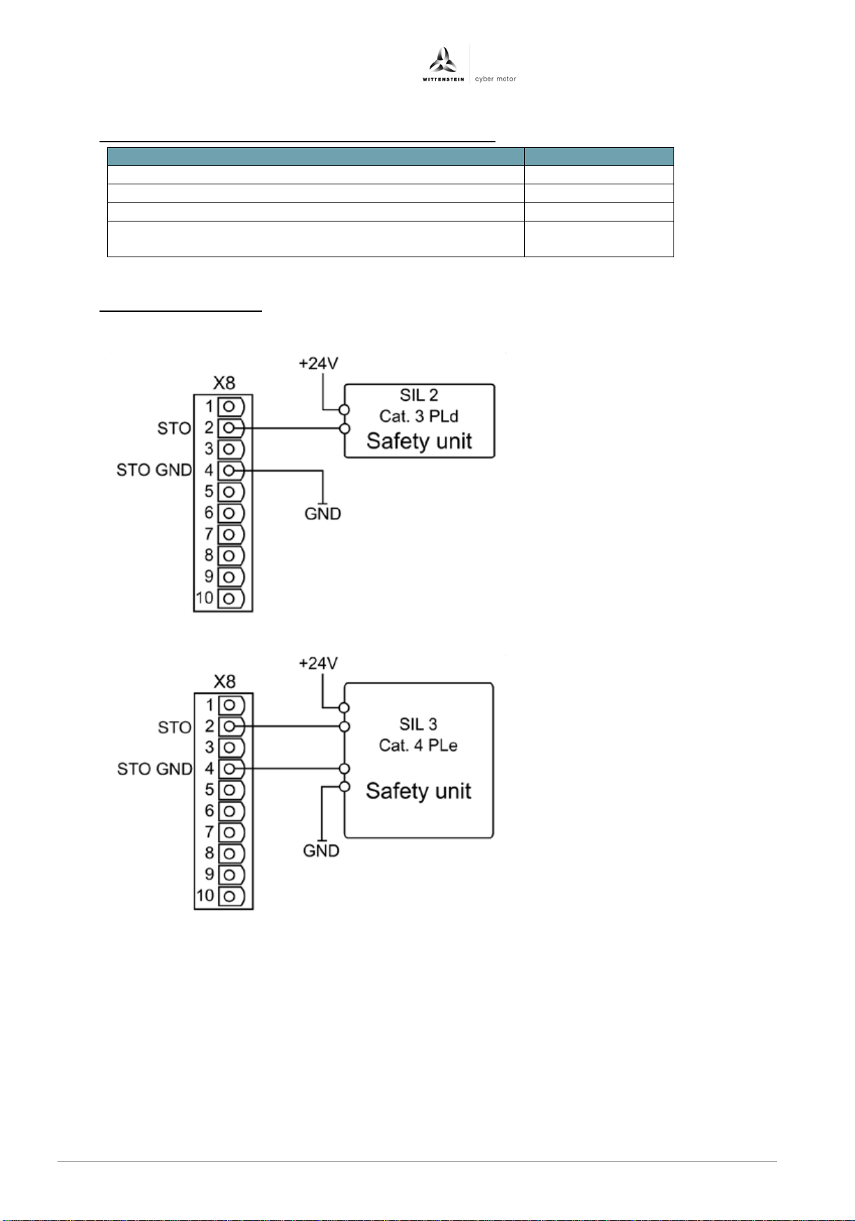
SIL 2 / category 3 PLd:
SIL 3 / category 4 PLe:
en-30 4022- D048047 Revision: 04
Page 33
Operating Manual simco® drive SIM2050
deutsch
english
italiano
deutsch
english
français
italiano
español
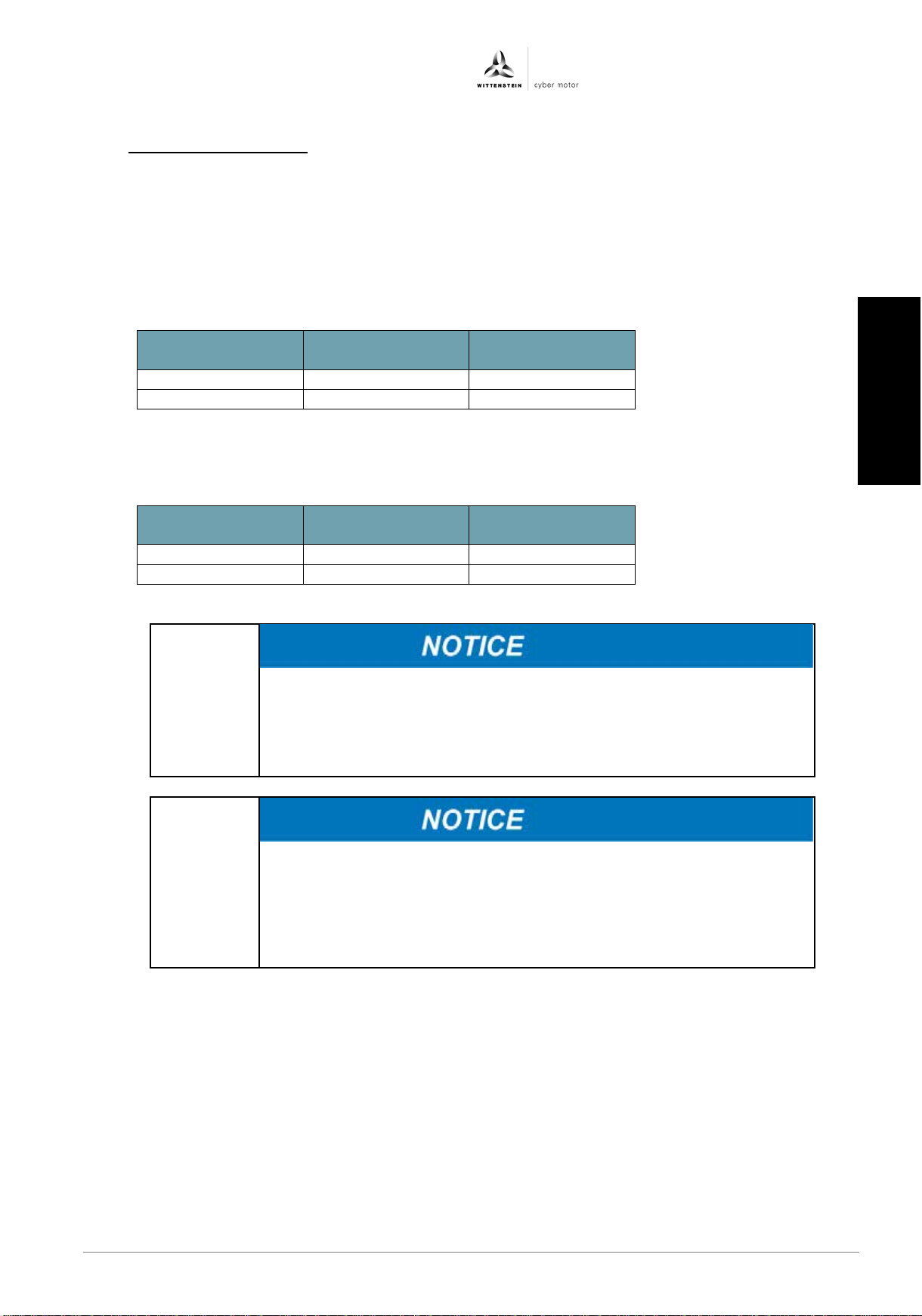
STO +24 V status
STO GND status
Motor torque
possible
Open
0 VDC
no
+24 VDC
0 VDC
yes
STO +24 V status
STO GND status
Motor torque
possible
Open
Open
no
+24 VDC
0 VDC
yes
• When wiring the STO inputs inside an installation space, make sure
•
permanent installation and protected from external damage.
• If the STO safety function is not required in an application, the STO
Machinery Directive.
10.8 Function description
Use of the STO safety function requires the inputs STO and STO GND to be connected to
the outputs of a safety control or safety relay that fulfills at least the requirements of PLd to
EN 13849-1 or SIL 2 to EN 61508.
Single-channel control SIL 2 / PLd:
With single-channel control of the STO safety function, the STO input is switched on by an
output of a safety relay. The STO GND is permanently connected to the GND of the safety
relay.
Two-channel control SIL 3 / PLe:
With two-channel control of the STO safety function, the STO and STO GND shutdowns
are switched separately by two outputs of a safety control.
If the wiring is outside the installation space, it must be routed in a
that both the wiring used and the installation space itself meet the
requirements of EN 60204-1.
input must be permanently connected directly to +24 VDC and the
STO GND input must be permanently connected directly to GND.
The STO function is thus shunted out and cannot be used. The drive
amplifier is then no longer a safety component as defined by the
Revision: 04 4022-D048047 en-31
日本語
Page 34
simco® drive SIM2050 Operating Manual
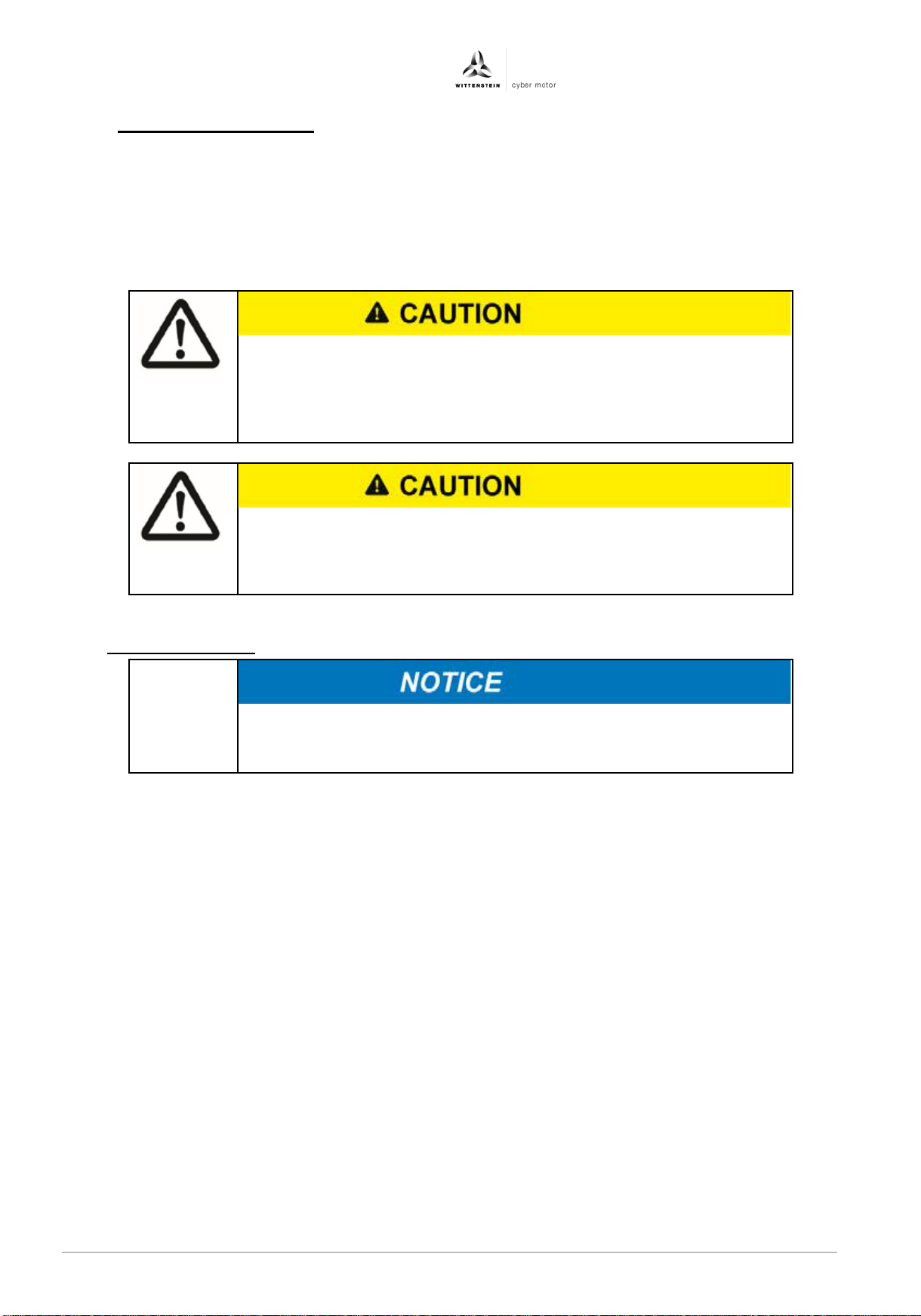
The drive amplifier cannot hold the load with the STO function
•
as well (e.g. with a suitable holding brake)
If the STO function is actuated during operation, the drive will coast
• The STO function must be checked at initial startup, after any work
of the system.
10.8.1 Safe operation sequence
If an application requires controlled braking before the use of the STO function, the drive must be
braked first and the STO function must be triggered with a time delay:
1. Controlled braking of drive
2. Once standstill is reached, disable the drive amplifier
3. In the case of a suspended load, mechanically lock the drive as well
4. Trigger STO
activated because the motor no longer supplies any torque. Risk of
injury from suspended load.
Drives with a suspended load must be securely locked mechanically
to a stop in an uncontrolled manner. Controlled braking of the drive
will not be possible. Danger from uncontrolled movement.
10.9 Functional check
Steps to follow for a functional check:
1. Stop the drive. The drive amplifier remains enabled and under control.
2. Activate the STO function by triggering an emergency stop of the machine. The drive
amplifier should enter its fault state and should issue the "ERROR_AMP_STO_ACTIVE"
fault.
3. Reset the fault using the "clear fault" function
4. Acknowledge the emergency stop and deactivate the STO function
5. Enable the drive and check that the drive is functioning
on the system's wiring, and after replacing one or more components
en-32 4022- D048047 Revision: 04
Page 35
 Loading...