

Page 1
4022-D045530 Revision: 02
Operating Manual
premo
SP Line / TP Line / XP Line
Page 2

Customer Service department
WITTENSTEIN alpha GmbH
Walter-Wittenstein-Straße 1
D-97999 Igersheim
Germany
Consulting hotline for startup:
+49 7931 493-14800
Türkiye
WITTENSTEIN Güç Aktarma
Sistemleri Tic. Ltd. Şti.
Türkiye
WITTENSTEIN Güç Aktarma
Sistemleri Tic. Ltd. Şti.
[email protected] +90 216 709 21 23
ྎ‴ ጾ㦐᪁ᆠ᭷㝈බྖ
[email protected] +886 3 287 0191
᪥ᮏ ࣦࢵࢸࣥࢩࣗࢱࣥᰴᘧ♫
[email protected] +81-3-6680-2835
ѝഭ ေ㞮ᯟඖ˄ᶝᐎ˅ᇎъᴹ䲀ޜ
[email protected] +86 571 8869 5856
© WITTENSTEIN alpha GmbH 2019
Subject to technical and content changes without notice.
premo
4022-D045530 Revision: 02
Page 3

premo
Contents
1 About this manual ................................................................................................3
1.1 Signal words ........................................................................................................3
1.2 Safety symbols.....................................................................................................4
1.3 Design of the safety instructions ..........................................................................4
1.4 Information symbols.............................................................................................4
2 Safety.....................................................................................................................5
2.1 EU Low Voltage Directive ....................................................................................5
2.2 Dangers ...............................................................................................................5
2.3 Personnel.............................................................................................................5
2.4 Intended use ........................................................................................................5
2.5 Reasonably foreseeable misuse..........................................................................6
2.6 Guarantee and liability .........................................................................................6
2.7 General safety instructions ..................................................................................6
2.8 Safety signs .........................................................................................................8
3 Description of the servo actuator .......................................................................9
3.1 Name plate.........................................................................................................10
3.2 Ordering code ....................................................................................................11
3.3 Performance statistics........................................................................................12
3.4 Weight................................................................................................................12
3.4.1 Weight of premo SP line................................................................................12
3.4.2 Weight of premo TP line................................................................................13
3.4.3 Weight of premo XP line................................................................................13
4 Transport and storage .......................................................................................14
4.1 Scope of delivery ...............................................................................................14
4.2 Packaging ..........................................................................................................14
4.3 Transport............................................................................................................14
4.4 Storage ..............................................................................................................14
5 Assembly ............................................................................................................15
5.1 Preparations.......................................................................................................15
5.2 Mounting the servo actuator onto a machine....................................................15
5.2.1 Mounting premo SP line on a machine ........................................................16
5.2.2 Mounting premo TP line on a machine.........................................................16
5.2.3 Mounting premo XP line with slotted holes on a machine (optional)............17
5.3 Components mounted on the output side ..........................................................18
5.4 Installing electrical connections .........................................................................19
6 Startup and operation ........................................................................................20
6.1 Safety instructions and operating conditions .....................................................20
6.2 Data for the electrical startup .............................................................................20
7 Maintenance and disposal.................................................................................21
7.1 Maintenance work..............................................................................................21
7.1.1 Refreshment of holding brake .......................................................................21
7.1.2 Visual inspection ...........................................................................................22
7.1.3 Checking the tightening torques....................................................................22
7.1.4 Cleaning ........................................................................................................22
7.2 Startup after maintenance work .........................................................................22
7.3 Maintenance schedule .......................................................................................23
7.4 Information on the lubricant used.......................................................................23
7.5 Disposal .............................................................................................................23
8 Malfunctions .......................................................................................................24
Revision: 02 4022-D045530 en-1
Page 4

9 Appendix ............................................................................................................ 26
9.1 Specifications for mounting on a machine......................................................... 26
9.1.1 Specifications for mounting premo SP line................................................... 26
9.1.2 Specifications for mounting premo TP line ................................................... 26
9.1.3 Specifications for mounting premo XP line................................................... 26
9.2 Specifications for mounting on the output side.................................................. 27
9.2.1 Thread in output flange, premo TP line ........................................................ 27
9.3 Tightening torques for common thread sizes in
general mechanical engineering ....................................................................... 27
9.4 Technical specifications .................................................................................... 28
9.4.1 Motor specifications, premo 320 V ............................................................... 28
9.4.2 Motor specifications, premo 560 V ............................................................... 29
9.4.3 Technical specifications for resolver............................................................. 30
9.4.4 Technical specifications of Hiperface absolute encoder Singleturn.............. 30
9.4.5 Technical specifications of Hiperface absolute encoder Multiturn................ 30
9.4.6 Technical specifications of Hiperface DSL absolute encoder Singleturn...... 31
9.4.7 Technical specifications of Hiperface DSL absolute encoder Multiturn........ 31
9.4.8 Technical specifications of EnDat 2.1 absolute encoder Singleturn............. 31
9.4.9 Technical specifications of EnDat 2.1 absolute encoder Multiturn ............... 32
9.4.10Technical specifications of EnDat 2.2 absolute encoder Singleturn ............ 32
9.4.11Technical specifications of EnDat 2.2 absolute encoder Multiturn............... 32
9.4.12Technical specifications of DRIVE-CLiQ absolute encoder Singleturn........ 33
9.4.13Technical specifications of DRIVE-CLiQ absolute encoder Multiturn .......... 33
9.4.14Technical specifications of Hiperface absolute encoder Singleturn
(compatible with Rockwell) ........................................................................... 33
9.4.15Technical specifications of Hiperface absolute encoder Multiturn
(compatible with Rockwell) ........................................................................... 34
9.4.16Technical specifications of Hiperface DSL absolute encoder Singleturn
(compatible with Rockwell) ........................................................................... 34
9.4.17Technical specifications of Hiperface DSL absolute encoder Multiturn
(compatible with Rockwell) ........................................................................... 34
9.4.18Technical specifications Heidenhain Incremental........................................ 35
9.4.19Technical specifications temperature sensors KTY and PT 1000 ............... 35
9.4.20Technical specifications of PTC temperature sensor................................... 36
9.4.21Technical specifications of premo brake...................................................... 37
9.4.22Pin assignment 1 ......................................................................................... 38
9.4.23Pin assignment 2 ......................................................................................... 41
9.4.24Pin assignment 4 ......................................................................................... 42
9.4.25Pin assignment 5 ......................................................................................... 45
9.4.26Pin assignment 6 ......................................................................................... 47
9.4.27Pin assignment 8 ......................................................................................... 49
9.4.28Pin assignment 9 ......................................................................................... 50
9.4.29Cable setup / Cable cross-section ............................................................... 50
premo
en-2 4022-D045530 Revision: 02
Page 5
premo About this manual
1 About this manual
These instructions contain information necessary for the safe operation of the premo servo
actuator, referred to as the servo actuator in the following.
If this manual is supplied with an amendment (e.g. for special applications), then the information in
the amendment is valid. Contradictory specifications in this manual thereby become void.
In case of questions on the special applications, please contact WITTENSTEIN alpha GmbH.
The operator must ensure that these instructions are read through by all persons assigned to install,
operate, or maintain the servo actuator, and that they fully comprehend them.
Store these instructions within reach of the servo actuator.
These safety instructions should be shared with colleagues working in the vicinity of the device
to ensure individual safety.
The original instructions were prepared in German; all other language versions are translations of
these instructions.
1.1 Signal words
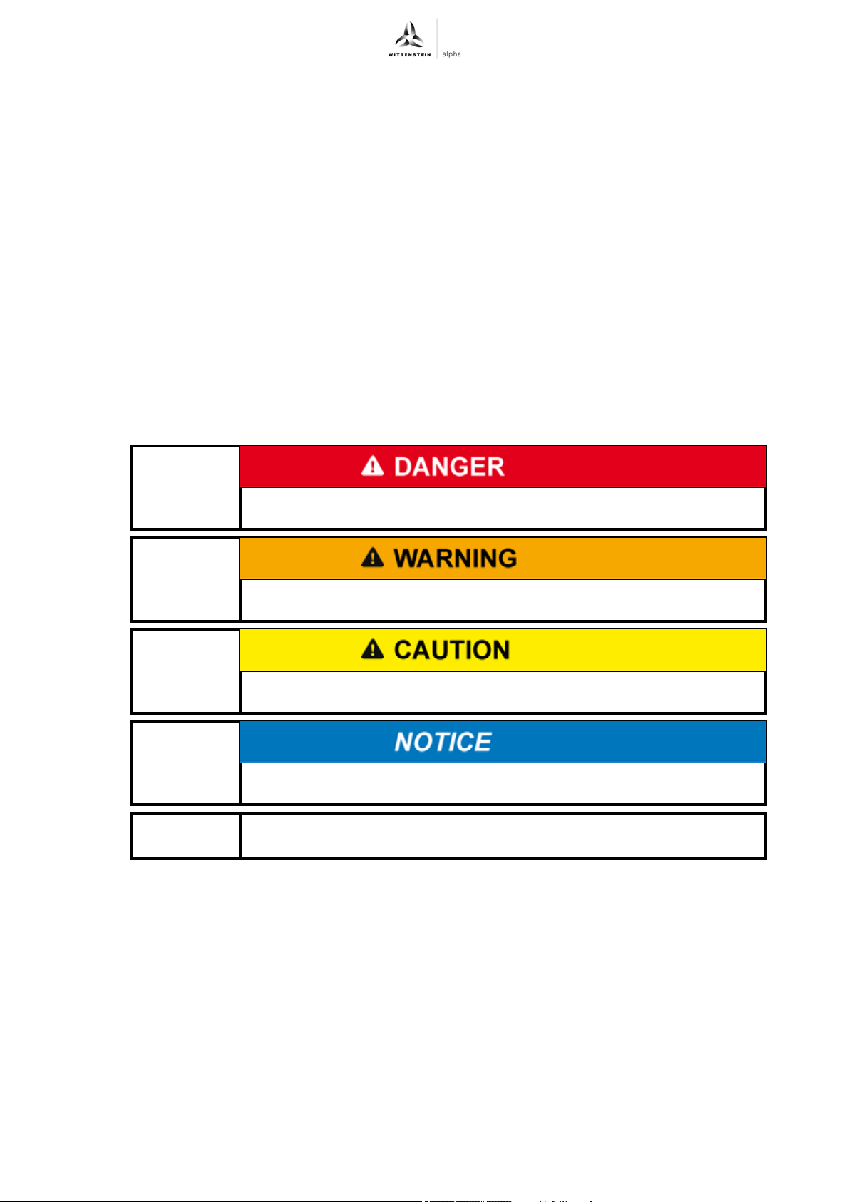
The following signal words are used to indicate possible hazards, prohibitions, and important
information:
This signal word indicates an imminent danger that will cause serious
injuries or even death.
This signal word indicates a potential hazard that could cause serious
injuries and even death.
This signal word indicates a potential hazard that could cause minor
or serious injuries.
This signal word indicates a potential hazard that could lead to
material damage.
A note without signal word draws your attention to application tips or
especially important information when handling the servo actuator.
Revision: 02 4022-D045530 en-3
Page 6
About this manual premo
1.2 Safety symbols
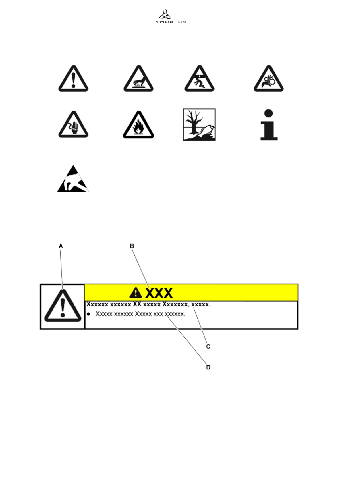
The following safety symbols are used to indicate possible hazards, prohibitions, and important
information:
General danger Hot surface Suspended loads Danger of being pulled in
Electric voltage Flammable Harmful to the
Component sensitive to
electrostatic discharge
1.3 Design of the safety instructions
The safety instructions of these instructions are designed according to the following pattern:
Information
environment
A = Safety symbol (see Chapter 1.2 "Safety symbols")
B = Signal word (see Chapter 1.1 "Signal words")
C = Type and consequence of the danger
D = Prevention of the danger
1.4 Information symbols
The following information symbols are used:
Indicates an action to be performed
Indicates the results of an action
Provides additional information on handling
en-4 4022-D045530 Revision: 02
Page 7

premo Safety
2 Safety
This operating manual, especially the safety instructions and the rules and regulations valid for the
operating site, must be observed by all persons working with the servo actuator.
In addition to the safety instructions in this manual, also observe any (legal and otherwise)
applicable environmental and accident prevention rules and regulations (e.g. personal safety
equipment).
2.1 EU Low Voltage Directive
The servo actuator has been constructed in accordance with the directive 2014/35/EU. Observe
applicable regulations for electrical installation (e.g. wire gauge, fuses).
It is the responsibility of the manufacturer of the plant to ensure all requirements for the entire
system are fulfilled.
2.2 Dangers
The servo actuator has been constructed according to current technological standards and
accepted safety regulations.
To avoid danger to the operator or damage to the machine, the servo actuator may be put to use
only for its intended usage (see Chapter 2.4 "Intended use") and in a technically flawless and safe
state.
Read the general safety instructions before beginning work (see Chapter 2.7 "General safety
instructions").
2.3 Personnel
Only technicians who have read and understood this operating manual may perform work on the
servo actuator. Based on their training and experience, technicians must be able to evaluate the
tasks assigned to them, in order to recognize and avoid risks.
2.4 Intended use
The servo actuator is designed to be installed in or connected to the following machines, incomplete
machines or equipment:
- Stationary large-scale plant,
- Stationary industrial tools,
- Movable machines, not intended for road use and only provided for professional (industrial)
use
In particular the following points must be observed:
- The servo actuator must be controlled by a servo controller.
- The servo actuator must not be used in applications with special environmental conditions e.g.
vacuum, potentially explosive atmospheres, clean room or areas with radioactive
contamination.
- Additional points must be observed for use in the food industry or the pharmaceutical industry:
- The servo actuator may only be used next to or under the foodstuff/product area.
- Observe also 7.4 "Information on the lubricant used".
- For risk-free operation, required safety devices have to be present, properly installed, and fully
functional. They may not be removed, changed, bridged, or rendered ineffective.
- In case of an emergency shutdown, power failure and or damage to the electrical equipment,
the servo actuator must be
- switched off immediately,
- secured against uncontrolled re-activation,
- secured against uncontrolled after-running.
- The optionally installed brake is simply a holding brake and may only be utilized in emergency
stop situations for braking the running servo actuator.
Revision: 02 4022-D045530 en-5
Page 8
Safety premo
2.5 Reasonably foreseeable misuse
Any use that deviates from the approved technical data (e.g. speed, force, torque, temperature) is
not use as intended and is therefore not permitted.
In particular the following applications are not permitted:
- Operation of the servo actuator, without properly installing it in or connecting it to other
machines or other partly completed machines or equipment.
- Operation of the servo actuators in a defective state
- Operation of the servo actuator, without determining that the machine in which it is to be
installed complies with the provisions of the Machinery Directive 2006/42/EC.
- Operation of the servo actuator in a potentially explosive environment
- Assembly of the servo actuator without prior acknowledgment of the operating / assembly
manual
- Operation of the servo actuator without legible warning and information signs
- Use of improper lubricants
- Use of unsuitable servo controllers
- Use in improper installation, operating, performance and ambient conditions
- Assembly of the servo actuator by insufficiently competent personnel
2.6 Guarantee and liability
Guarantee and liability claims are excluded for personal injury and material damage in case of
- Ignoring the information on transport and storage
- Improper use (misuse)
- Improper or neglected maintenance and repair
- Improper assembly / disassembly or improper operation (e.g. test run without secure
attachment)
- Operation of the servo actuator when safety devices and equipment are defective
- Operation of the servo actuator without lubricant
- Operation of a heavily soiled servo actuator
- Modifications or reconstructions that have been carried out without the approval of
WITTENSTEIN alpha GmbH
2.7 General safety instructions
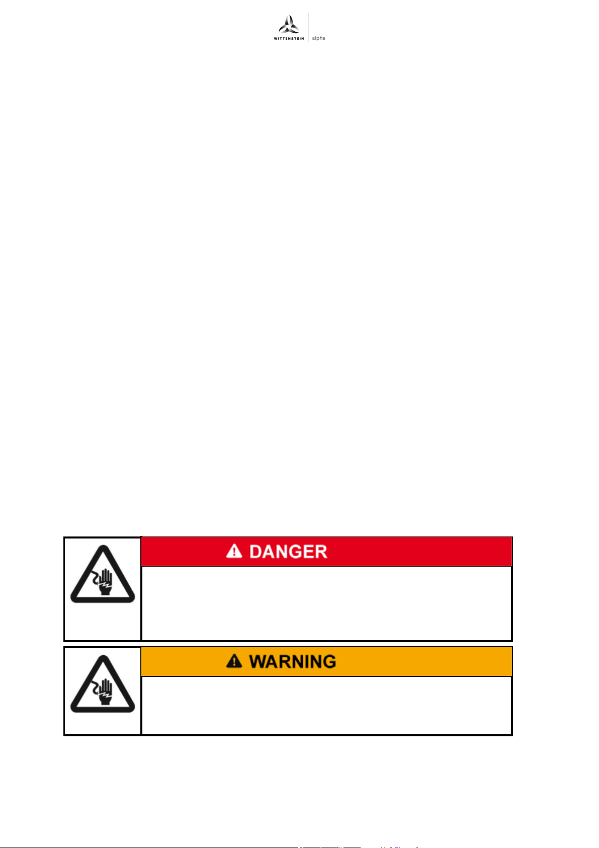
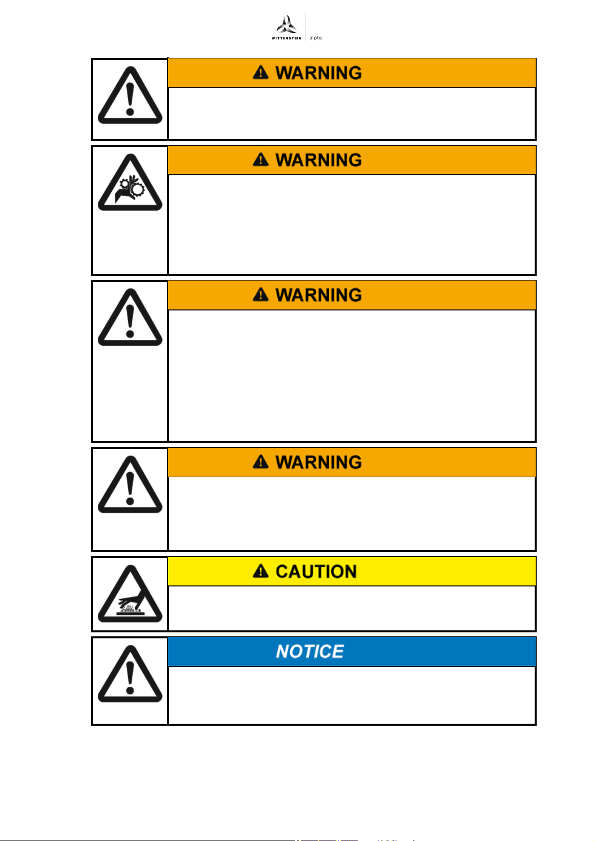
Faulty electrical connections or not approved, current-carrying
components can cause serious injuries and even death.
Have all electrical connection work performed by qualified technicians
only.
Immediately replace damaged cables or plugs.
During generator operation, voltage is induced. This can lead to lethal
current pulses.
Ensure that no plugs and connections are laying open during generator
operation.
en-6 4022-D045530 Revision: 02
Page 9
premo Safety
Objects flung out by rotating components can cause serious injuries.
Remove objects and tools from the servo actuator before putting it into
operation.
Rotating components on the servo actuator can pull in parts of the
body and cause serious injuries and even death.
Keep a sufficient distance to rotating machinery while the servo actuator
is running.
Secure the machine against restarting and unintentional movements
during assembly and maintenance work (e.g. uncontrolled lowering of
lifting axes).
A wrong direction of rotation or direction of movement may result in
serious injury or death.
The direction of rotation or movement may differ from the standard
IEC 60034–8.
Before and during startup, ensure that the servo actuator has the correct
direction of rotation or movement.
Be sure to avoid collision (caused e.g. by crashing against an end stop).
With the danger area secured, check the direction of rotation or
movement in a slow motion, ideally by limiting the current and torque.
A damaged servo actuator can cause accidents with the risk of injury.
Never operate a servo actuator that has been overloaded due to misuse
or a machine crash (see Chapter 2.5 "Reasonably foreseeable misuse").
Replace the affected servo actuators, even if no external damage is
visible.
Hot servo actuator housing (up to 125 °C) can cause serious burns.
Touch the servo actuator housing only when wearing protective gloves
or after the servo actuator has been idle for some time.
Loose or overloaded screw connections can damage the servo
actuator.
Always use a calibrated torque wrench to tighten and check all screw
connections for which a tightening torque has been specified.
Revision: 02 4022-D045530 en-7
Page 10
Safety premo
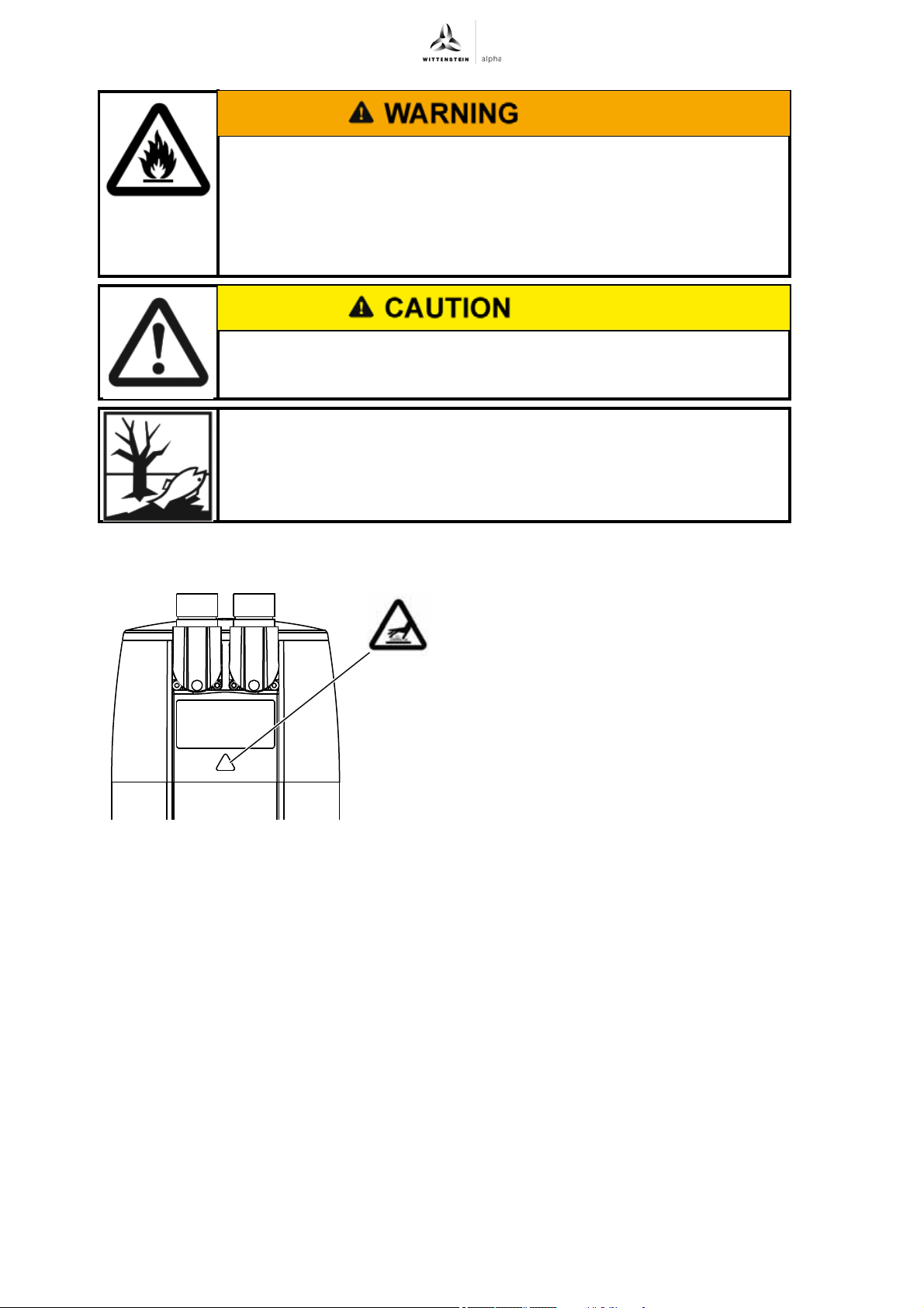
Lubricants are flammable.
Do not spray with water to extinguish.
Suitable extinguishing agents are powder, foam, water mist and carbon
dioxide.
Observe the safety instructions of the lubricant manufacturer (see
Chapter 7.4 "Information on the lubricant used").
Solvents and lubricants can cause skin irritations.
Avoid direct skin contact.
Solvents and lubricants can pollute soil and water.
Use and dispose of cleaning solvents and lubricants properly.
2.8 Safety signs
There is a safety sign on the servo actuator
housing that warns against hot surfaces. This
safety sign may not be removed.
en-8 4022-D045530 Revision: 02
Page 11
premo Description of the servo actuator
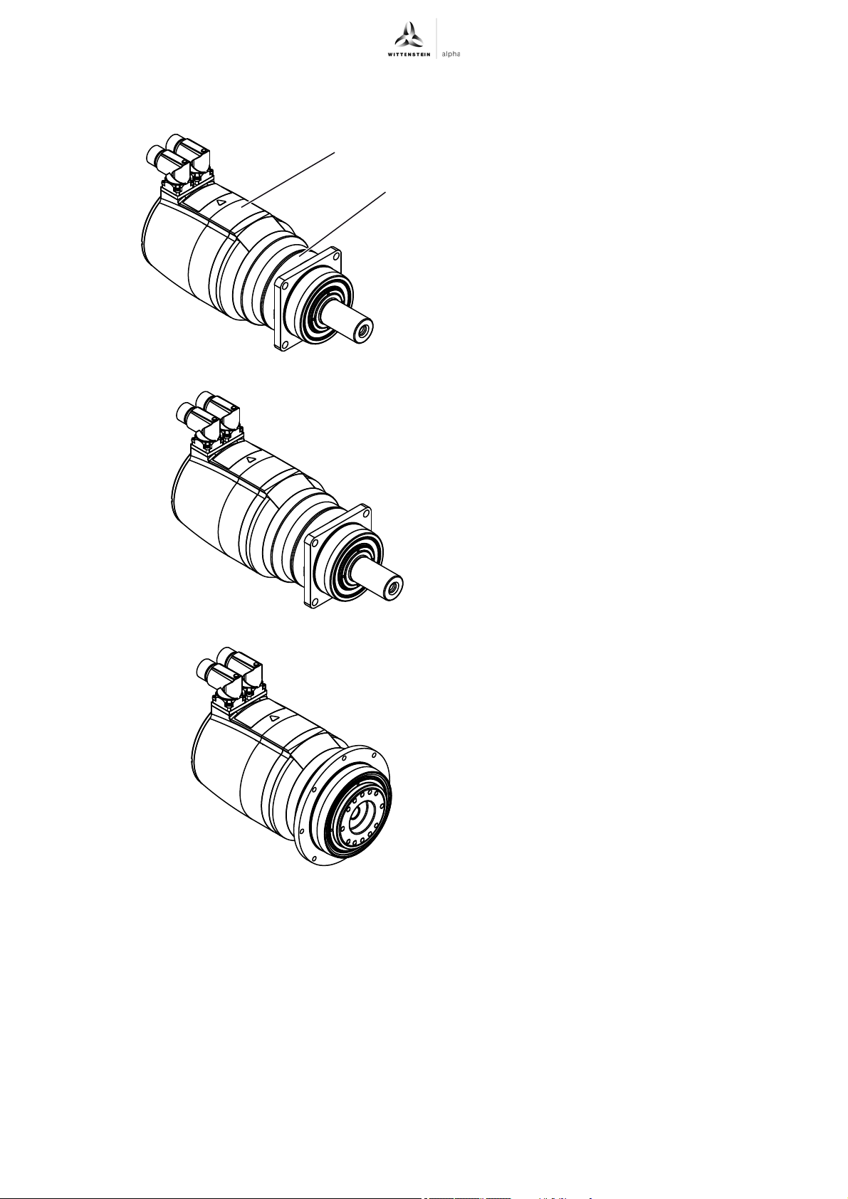
3 Description of the servo actuator
A
B
The servo actuator is a combination of a lowbacklash planetary gearbox (B) and an AC
servomotor (A).
The AC servomotor is a brushless 3-phase
synchronous motor with excitation by means of
permanent magnets located on the rotor. A resolver
or optical encoder takes care of the commutation or
speed regulation. An optional permanent-magnet
holding brake is integrated into the motor.
The standard manufactured versions of the premo
SP line and the premo XP line output shaft are as
follows:
- Smooth output shaft
- Grooved output shaft
- Involute gearing
The premo TP line output shaft is constructed as
an output flange.
Revision: 02 4022-D045530 en-9
Page 12
Description of the servo actuator premo
WITTENSTEIN alpha GmbH
Walter-Wittenstein-Str. 1 | 97999 Igersheim
Mat.no.: 40000001-00-0
SN: 1234567
PBG 33FS-016FP01-6MKGTCW01
DIN EN 60034-1
P
N
[W]: 750
3~ PMSM
I
N
[A]: 4,19
n
1N
[min-1]: 2256
DRIVE: SIEMEN
Date KW/JJ
U
DC
[V]: 750
Ratio i: 16
n
1max
[min-1]: 6000
Th. Cl.: F I 155°C
Pos: XXX
I 0 [A]: 6,71
U
inN
[V]: 132
IP 65
Cust.mat.no.: 1735198
Lubrication: Oil OPTIG. SYNT. 800/220
E
N
F
G H I
J
K L
M
O
P Q
R S
T
UV
X
ABC
D
W
3.1 Name plate
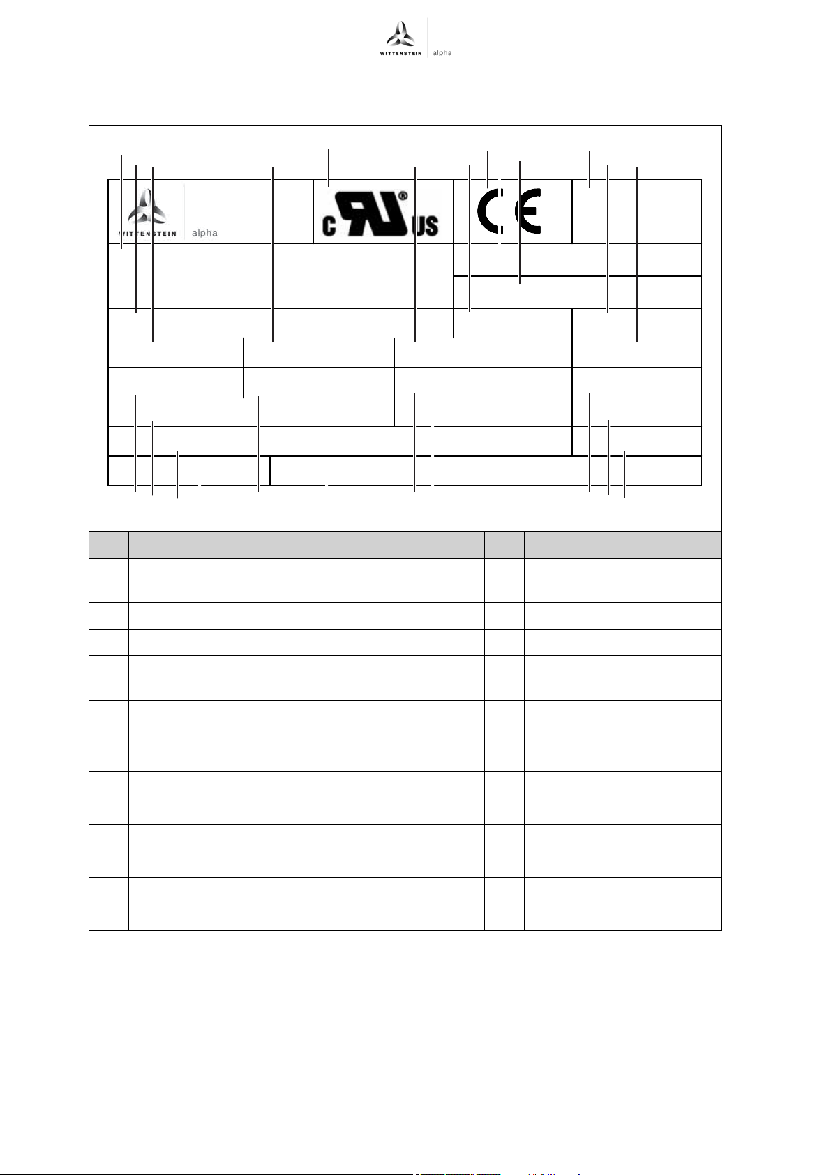
The name plate is attached to the servo actuator housing.
Designation Designation
A UL identification "cURus" M Continuous stall current of
B CE identification N Nominal output
C Placeholder: QR code O Nominal current of actuator
D Address of manufacturer P Insulating material class /
E Material number / article code Q Induced voltage for nominal
F Serial number R Nominal input speed
G Ordering code (see 3.2 "Ordering code") S Protection class
H Operating voltage T Production date
I Gear ratio U Lubricant
J Rating according to standard V Mounting position
K Motor type W Servo converter
L Max. input speed X Customer material number
Tbl-1: Name plate
the motor
max. winding temperature
speed
en-10 4022-D045530 Revision: 02
Page 13
premo Description of the servo actuator
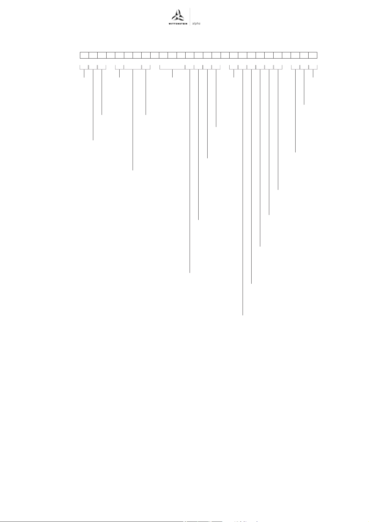
3.2 Ordering code
123456789012345678901234567
PAG 11CS–025FP01–6MPGSC–W01
®
premo
Product line
B = SP Line
A = TP Line
H = XP Line
Size
1
2
3
Sector package
G = General
Stator length
and Stator size
See next page
for options
Ratio
Characteristic
S = Standard
R = Flange with
slotted holes
(XP Line only)
Operating
voltage
5 = 320V
6 = 560V
Backlash
1 = Standard
0 = Reduced
Output shape
0 = Smooth shaft /
Flange
1 = Shaft with key /
Flange with
index bore
2 = Splined shaft
(DIN 5480)
3 = System output
4 = Other
Lubrication
P = Oil
G = Grease
F = Food-grade oil
H = Food-grade grease
Pin assignment
See next page
for options
Orientation
to flange
0 = 0°
1 = 90°
2 = 180°
3 = 270°
Electrical connection
See next page
for options
Cooling
C = Natural convection cooling
Brake type
S = Standard brake i = 40 – 100
T = Standard brake i = 16 – 35
0 = Without brake
Winding code
is assigned
by WITTENSTEIN
Gearbox model
F = Standard
Encoder
See next page
for options
Temperature sensor
P = PTC STM 160
T = PT1000
K = KTY 84-130
Revision: 02 4022-D045530 en-11
Page 14
Description of the servo actuator premo
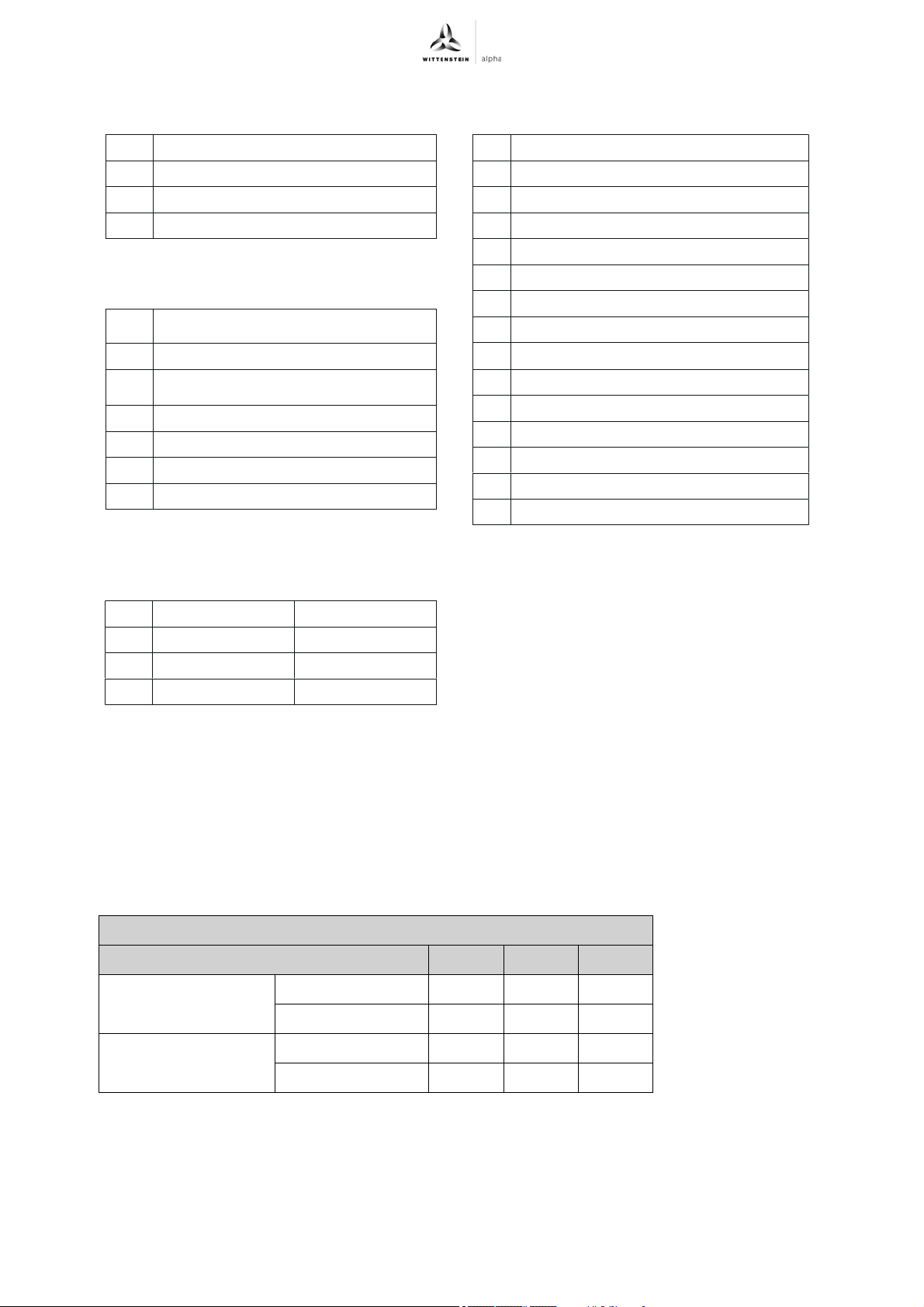
R Angled integral socket, 1-cab
W Angled integral socket, 2-cab
S Straight integral socket, 1-cab
G Straight integral socket, 2-cab
1
WITTENSTEIN alpha-Standard
Temp. sensor in signal cable
2 Siemens-compatible
4
WITTENSTEIN alpha-Standard
Temp. sensor in power cable
5 Rockwell-compatible
6 B&R-compatible
8 Schneider-compatible
9 Beckhoff-compatible
R
S
M
F
W
N
K
G
L
D
E
V
J
P
Ratio 16 to 35 Ratio 40 to 100
Size1 2C 1C
Size2 2D 1D
Size3 3F 1F
Electrical connection options
Pin assignment options
Encoder options
Stator length and stator size options
H
Resolver, 2-pin
EnDat 2.1 absolute, singleturn
EnDat 2.1 absolute, multiturn
EnDat 2.2 absolute, singleturn
EnDat 2.2 absolute, multiturn
HIPERFACE® absolute, singleturn
HIPERFACE® absolute, multiturn
HIPERFACE DSL* Safety absolute, singleturn
DRIVE-CliQ absolute, singleturn
DRIVE-CliQ absolute, multiturn
Rockwell absolute, singleturn
Rockwell absolute, multiturn
Rockwell DSL absolute, singleturn
Rockwell DSL absolute, multiturn
HIPERFACE DSL* Safety absolute, multiturn
3.3 Performance statistics
3.4 Weight
Refer to Chapter 9.4 "Technical specifications" for the maximum permitted speeds and torques.
The standard weights of the servo actuators (with resolver / encoder) are specified in the
tables "Tbl-2", "Tbl-3" and "Tbl-4". Depending on the design, the actual weight can deviate by up to
20 %.
3.4.1 Weight of premo SP line
Without brake i = 16 – 35 3.6 5.6 11.7
Size of premo SP line Size 1 Size 2 Size 3
With brake i = 16 – 35 4.1 6.5 13.4
Weight [kg]
i = 40 – 100 3.2 5.1 10.0
i = 40 – 100 3.5 5.5 10.6
Tbl-2: Weight of premo SP line [kg]
en-12 4022-D045530 Revision: 02
Page 15
premo Description of the servo actuator
3.4.2 Weight of premo TP line
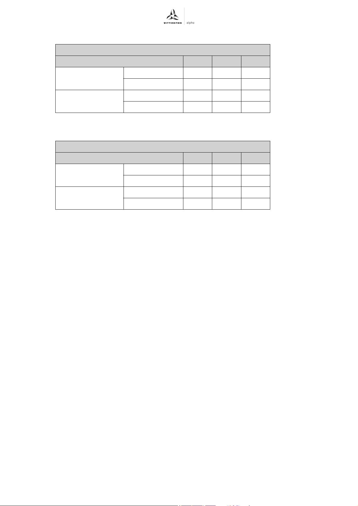
Weight [kg]
Size of premo TP line Size 1 Size 2 Size 3
Without brake i = 16 – 35 3.1 5.6 10.5
i = 40 – 100 2.7 5.1 8.8
With brake i = 16 – 35 3.6 6.5 12.2
i = 40 – 100 3.0 5.5 9.4
Tbl-3: Weight of premo TP line [kg]
3.4.3 Weight of premo XP line
Weight [kg]
Size of premo XP line Size 1 Size 2 Size 3
Without brake i = 16 – 35 3.3 5.5 11.4
i = 40 – 100 2.9 5.0 9.7
With brake i = 16 – 35 3.8 6.4 13.1
i = 40 – 100 3.2 5.4 10.3
Tbl-4: Weight of premo XP line [kg]
Revision: 02 4022-D045530 en-13
Page 16
premo Transport and storage
4 Transport and storage
4.1 Scope of delivery
Check the completeness of the delivery against the delivery note.
Missing parts or damage must be notified immediately in writing to the carrier, the
insurance company, or WITTENSTEIN alpha GmbH.
4.2 Packaging
The servo actuator is delivered packed in foil and cardboard boxes.
Dispose of the packaging materials at the recycling sites intended for this purpose. Observe
the applicable national regulations concerning disposal.
4.3 Transport
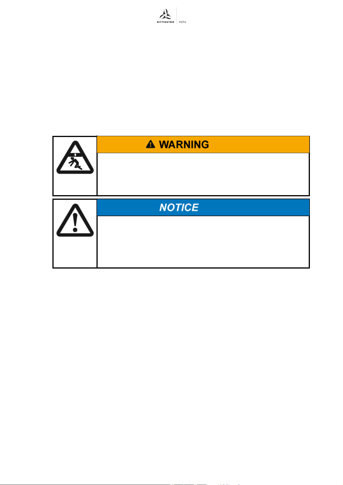
Suspended loads can fall and can cause serious injuries and even
death.
Do not stand under suspended loads.
Secure the servo actuator with suitable fasteners (e.g. belts) before
transport.
Specifications on the weights, refer to Chapter 3.4 "Weight".
Ambient temperatures between -20° C and +50° C are permissible for transport only.
Transport of servo actuators up to and including size 3
No special method is specified for transporting the servo actuator.
Lifting at the electrical connections or the output shaft / output flange is not permitted.
4.4 Storage
Store the servo actuator in horizontal position and dry surroundings at a temperature of
0C to + 30C in the original packaging. Store the servo actuator for a maximum of 2 years.
For storage logistics, we recommend the "first in –first out" method.
Hard knocks, because of falling or hard dropping, can damage the
servo actuator.
Only use hoisting equipment and lifting accessories with sufficient
capacity.
Never exceed the maximum permissible load for hoisting equipment.
Lower the servo actuator slowly.
Revision: 02 4022-D045530 en-14
Page 17
premo Assembly
5 Assembly
Read the general safety instructions before beginning work (see Chapter 2.7 "General safety
instructions").
5.1 Preparations
Many electronic components are sensitive to electrostatic discharge
(ESD). This particularly concerns integrated circuits (IC),
semiconductors, resistors with a tolerance of less than one percent as
well as transistors and other components such as encoders.
Observe the directives concerning ESD protection.
Pressurized air can damage the servo actuator seals.
Do not use pressurized air to clean the servo actuator.
Clean/de-grease the output shaft /output flange of the servo actuator with a clean, lint-free
cloth moistened with a suitable grease-dissolving but non-aggressive cleaning agent.
Dry all fitting surfaces to neighboring components in order to achieve the proper friction values
of the screw connections.
Check the fitting surfaces additionally for damage and impurities.
5.2 Mounting the servo actuator onto a machine
The servo actuator is compliant for every mounting position; the
lubricant quantity, however, is dependent on the mounting position.
The mounting position and the lubricant that has been filled in is
indicated on the identification plate (see Chapter 3.1 "Name plate").
Mount the servo actuator only in the specified mounting position.
Observe the safety and processing instructions for the threadlocker to be
used.
Revision: 02 4022-D045530 en-15
Page 18
Assembly premo
A
B
A
B
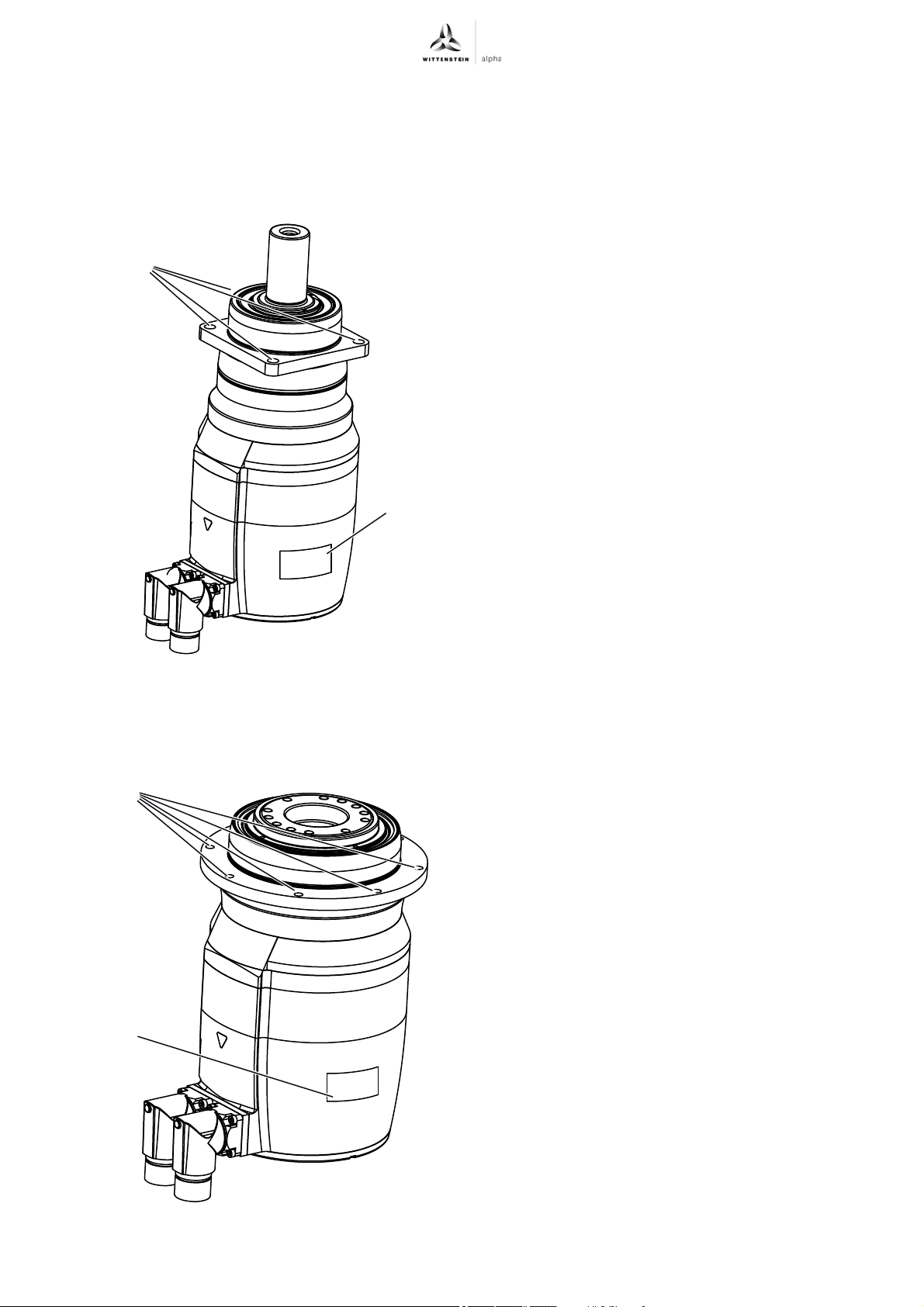
5.2.1 Mounting premo SP line on a machine premo SP line and premo XP line are equipped with a square flange with round through-holes for
mounting on a machine.
Alternatively premo XP line can have slotted holes, see Chapter 5.2.3 "Mounting premo XP line
with slotted holes on a machine (optional)".
Coat the fastening screws with a threadlocker
(e.g. Loctite
Fasten the servo actuator to the machine with
®
243).
the fastening screws through the throughholes (A).
Mount the servo actuator in such a way that
the name plate (B) remains legible.
Do not use any washers (e.g. plain
washers, tooth-lock washers).
For appropriate screw sizes and tightening
torques, see Chapter 9.1 "Specifications for
mounting on a machine", Tables "Tbl-11"
and "Tbl-13".
5.2.2 Mounting premo TP line on a machine premo TP line is equipped with a circular flange with round through-holes for mounting on a
machine.
Coat the fastening screws with a threadlocker
(e.g. Loctite
Fasten the servo actuator to the machine with
®
243).
the fastening screws through the throughholes (A).
Mount the servo actuator in such a way that
the name plate (B) remains legible.
Do not use any washers (e.g. plain
washers, tooth-lock washers).
For appropriate screw sizes and tightening
torques, see Chapter 9.1 "Specifications for
mounting on a machine", Table "Tbl-12".
en-16 4022-D045530 Revision: 02
Page 19
premo Assembly
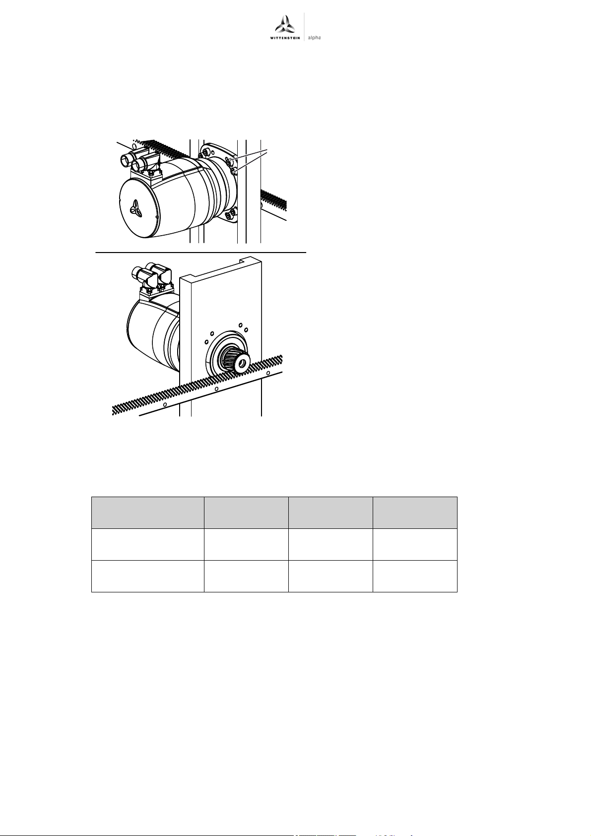
5.2.3 Mounting premo XP line with slotted holes on a machine (optional)
For adjusting the gearing backlash between output pinion and toothed rack / counter-wheel,
premo XP line features slotted holes and guides on the sides as an option. An additional
adjustment device is no longer necessary. The ground side surfaces can also be used as a torque
support.
A
Center the servo actuator by the ground side
surfaces in the sled.
Adjust gearing backlash between output pinion and
toothed rack / counter-wheel.
For the proper setting of the gearing backlash,
you will find further information in the "alpha
rack & pinion system" manual.
Use only the washers included with the delivery for
fastening the gearbox to the machine (see
Table "Tbl-5").
Slide the washers onto the fastening screws.
Smear threadlocker (e.g. Loctite 243) onto the
fastening screws.
Fasten the servo actuator to the machine with the
fastening screws through the slotted holes (A).
Mount the servo actuator in such a way that the
name plate remains legible.
For appropriate screw sizes and tightening
torques, see Chapter 9.1 "Specifications for
mounting on a machine", Table "Tbl-13".
Optionally, you can fixate the servo actuator to
the machine additionally with cylinder pins.
Further information can be found in section
"Pinning the mounted and aligned servo
actuator (optional)".
Size of premo XP
line
Outer diameter
[mm]
Clamping length
[mm]
Size 1 Size 2 Size 3
–1416
–56
Tbl-5: Dimensions of the washers
Revision: 02 4022-D045530 en-17
Page 20
Assembly premo
B
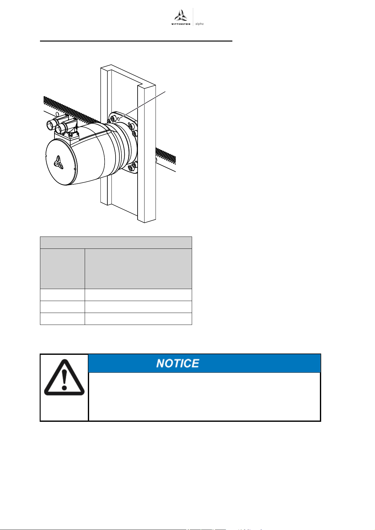
Pinning the mounted and aligned servo actuator (optional)
There are bore holes (B) on the housing for pinning the servo actuator to the machine.
Drill pin holes into the machine base according
to the bores (B) of the housing.
Ream the bores to the corresponding fit size for
the cylinder pins.
For specifications on the cylinder pins, refer
to Table "Tbl-6".
Fixate the servo actuator with the cylinder pins.
Pin holes in gear housing
Size Quantity x cylinder pin with
interior thread
DIN 7979
DIN EN ISO 8735 Form A
Size 1 –
Size 2 2 x 6 m6
Size 3 2 x 8 m6
Tbl-6: Pin holes
5.3 Components mounted on the output side
Distortions during assembly can damage the servo actuator.
Mount gearwheels and toothed belt pulleys onto the output shaft / output
flange without forcing.
Never attempt to assemble by force or hammering!
Only use suitable tools and devices for assembly.
The prescribed screw sizes and tightening torques for the output flange can be found in
Chapter 9.2 "Specifications for mounting on the output side", Table "Tbl-14".
en-18 4022-D045530 Revision: 02
Page 21
premo Assembly
5.4 Installing electrical connections
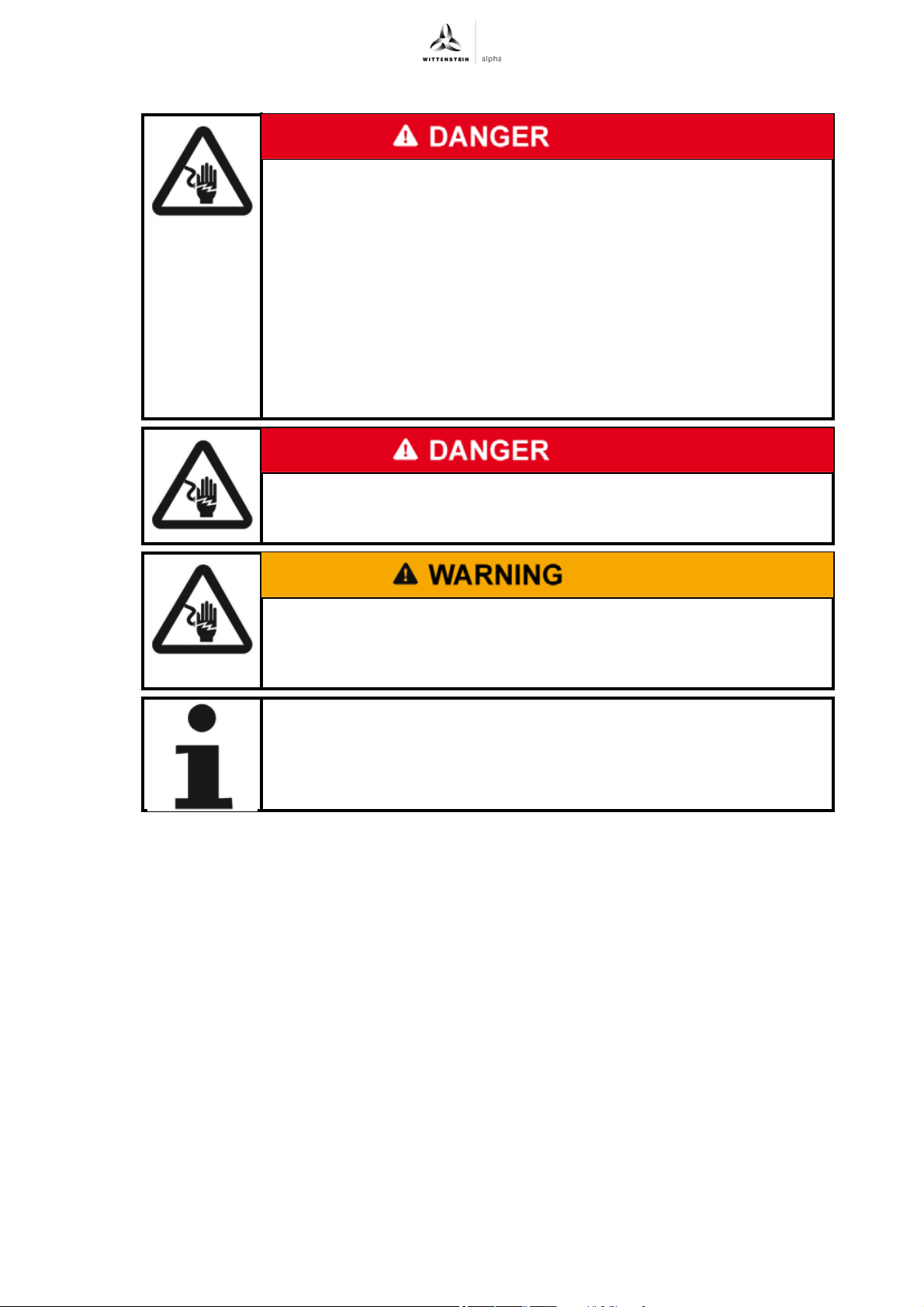
Electrically live components may result in electric shocks if touched
and can cause serious injuries and even death.
Observe the five safety rules of electrical engineering before starting
electrical installation work:
- Disconnect.
- Secure against being switched on again.
- Check that there is no voltage.
- Ground and short-circuit.
- Cover neighboring and electrified parts.
Check that protective caps are on the plugs. If protective caps are
missing, check the plugs for damage and soiling.
Electric operation in moist areas may result in electric shocks and can
cause serious injuries and even death.
Carry out the electrical assembly only in dry areas.
During generator operation, voltage is induced. This can lead to lethal
current pulses.
Ensure that no plugs and connections are exposed during generator
operation.
The cables of all servo actuators need to be laid out in such a way that
a minimum bending radius of 10 x diameter is kept. Torsional load of
the cables should be avoided.
In actuators of the respective series, connectors with bayonet coupling are used. These are
connectors with an additional vibration O-ring.
- When using M23 screw counter plugs, the O-ring remains in place to protect against
loosening due to vibration on the mounting socket.
- When using counter plugs with bayonet coupling the O-ring must be removed.
- The maximum line length without disconnection points is 50 m. Observe also the maximum
permissible line lengths of the servo converter being used.
Revision: 02 4022-D045530 en-19
Page 22
premo Startup and operation
6 Startup and operation
6.1 Safety instructions and operating conditions
Read the general safety instructions before beginning work (see Chapter 2.7 "General safety
instructions").
Wearing hearing protection in the vicinity of the servo actuator is recommended.
Improper use can cause damage to the servo actuator.
Ensure that
- The ambient temperature does not drop below 0 C or exceed +40
C,
- The surface temperature on the gearbox does not exceed +90C,
- The surface temperature on the engine does not exceed +115C,
- The installation altitude is not above 1000 m NHN.
For other conditions of use, consult our Customer Service department.
Use the sensor only up to its maximum limit values, see Chapter 9.4
"Technical specifications".
Only use the servo actuator in a clean, dust-free and dry environment.
Operate the servo actuator only in the mounting position that is specified
on the identification plate.
6.2 Data for the electrical startup
The specified data is intended for the electrical startup.
The servo controllers of the different manufacturers generally use an
individual annotation of the data.
If the data is disregarded, the drive and/or the servo controller may be
damaged.
Observe the listed units precisely and check their conformance with the
units of the servo controller.
If the units differ, make the necessary adjustment accordingly.
In some servo controllers, there is a dependence between the individual parameters. We would
be glad to assist you in finding the correct entries.
We provide adjusted and certified quick start guides for several servo controllers. In these
guides you will find the adapted parameter lists for the relevant servo converters.
For further information, please visit our website at http://wittenstein-alpha.de or contact our
Customer Service: [email protected]
This data reflects the technical characteristics and the limit values of the standard engines of the
premo series in general units. Possible restrictions due to the gearbox can be found in the data
sheet of your servo actuator.
Select the data for the premo version you are using.
- Chapter 9.4.1 "Motor specifications, premo 320 V"
- Chapter 9.4.2 "Motor specifications, premo 560 V"
Select the appropriate product size of the desired servo controller in regard to the application
data.
Revision: 02 4022-D045530 en-20
Page 23
premo Maintenance and disposal
7 Maintenance and disposal
Read the general safety instructions before beginning work (see Chapter 2.7 "General safety
instructions").
The permanent magnets of the stator send a strong magnetic field,
which becomes active during the disassembling of the servo actuator.
Observe the general safety instructions (e.g. for pacemaker patients) for
working in strong magnetic fields.
7.1 Maintenance work
The partial or complete disassembly of the actuator into its individual
parts for maintenance or repair work is not permissible.
In case of a malfunction or failure, please contact Customer Service.
7.1.1 Refreshment of holding brake
The holding torques of the holding brakes used in the actuators are influenced by various factors,
e.g. oxidation of abraded particles, flattening of friction surfaces due to frequent application of the
brakes in the same position or air gap changes due to wear. This can lead to a tolerance in the
holding torque of - 50 % to + 100 %.
The specified holding torques apply under optimal conditions, without damaging influences. The
deterioration of the holding torque can be reduced by refreshing the brakes periodically.
For critical applications we recommend dimensioning for an adequately large holding torque to take
account of these factors. Our internal technical service would be glad to help you with the
appropriate dimensioning.
A maintenance interval of 4 weeks is recommended for common industrial applications.
For your dimensioning, observe the effective torques during running-in.
Recommended brake refreshment cycle, premo
Ordering code: PxG xxxx-xxxxxxx-xxxxXxxxx-xxx (X= S or T)
Unit PxG 1 PxG 2 PxG 3
Slipping speed rpm 100
Duration for
sec 0,5
brake
deenergized
Duration for
sec 0,5
brake energized
Number of
–5
cycles
Tbl-7: Recommended brake refreshment cycle, premo
Revision: 02 4022-D045530 en-21
Page 24
Maintenance and disposal premo
7.1.2 Visual inspection
Check the entire servo actuator and all cables for exterior damage.
The radial shaft seals are subject to wear. Therefore, also check the servo actuator for
leakage during each visual inspection (lubricant leaks).
You can find more general information on radial shaft seals on our partner's Internet site at
http://www.simrit.de.
Check the mounting position, so that no foreign medium (e.g. oil) has collected on the
output flange.
Check whether the safety signs (see Chapter 2.8 "Safety signs") and the type plate (see
Chapter 3.1 "Name plate") are mounted and legible.
7.1.3 Checking the tightening torques
Check the tightening torque of the fastening screws on the servo actuator housing and at the
output flange.
The prescribed tightening torques can be found in Chapter 9.1 "Specifications for mounting
on a machine", Tables "Tbl-11", "Tbl-12"and "Tbl-13", and in Chapter 9.2 "Specifications
for mounting on the output side", Table "Tbl-14".
If, while checking the tightening torque, you discover that a screw can be further tightened,
follow the instructions in "Remounting the screw".
Remounting the screw
Loosen the screw.
Remove the glue residue from the threaded bore and the screw.
De-grease the screw.
Coat the screw with a threadlocker (e.g. Loctite
Insert the screw and tighten it with the specified torque.
7.1.4 Cleaning
Clean the servo actuator using a clean, lint-free cloth.
If necessary, use a suitable fat dissolving but non-aggressive cleaning agent.
Make sure that it is possible to remount the screw on the gearbox without
damaging the entire machine.
®
243).
Pressurized air can damage the servo actuator seals.
Do not use pressurized air to clean the servo actuator.
7.2 Startup after maintenance work
Clean the outside of the servo actuator.
Attach all safety devices.
Do a trial run before releasing the servo actuator again for operation.
en-22 4022-D045530 Revision: 02
Page 25
premo Maintenance and disposal
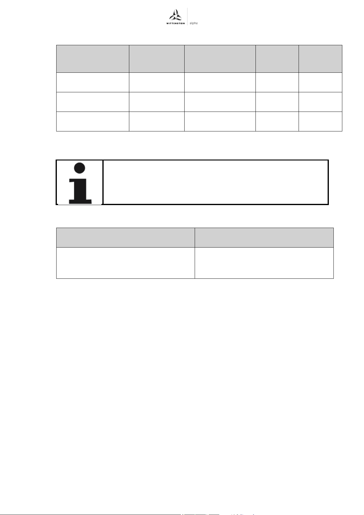
7.3 Maintenance schedule
Maintenance work At startup After the first 500
Refreshment of
holding brake
Visual inspection
XX X
and cleaning
Checking the
XX X
tightening torques
7.4 Information on the lubricant used
All servo actuators are permanently lubricated by the manufacturer with
synthetic gear oil (polyglycols) of viscosity class ISO VG100, ISO VG220 or
with a high-performance lubricant (see type plate). All bearings are
lubricated for life at the factory.
The manufacturer listed below will provide any further information on the lubricants:
operating hours or 3
months
Tbl-8: Maintenance schedule
Every 4
weeks
X
Yearly
Castrol Industrie GmbH, Mönchengladbach
7.5 Disposal
Consult our Customer Service Department for supplementary information on disassembly and
disposal of the servo actuator.
Dispose of the servo actuator at the recycling sites intended for this purpose.
Observe the locally valid regulations for disposals.
Standard lubricants Lubricants for the food industry (NSF-H1
registered)
Klüber Lubrication München KG, Munich
Tel.: + 49 2161 909-30
www.castrol.com
Tbl-9: Lubricant manufacturers
Tel.: + 49 89 7876–0
www.klueber.com
Revision: 02 4022-D045530 en-23
Page 26
premo Malfunctions
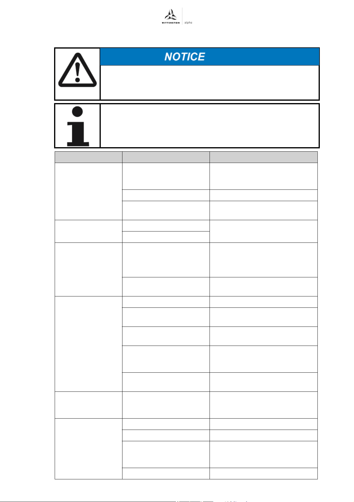
8 Malfunctions
Changed operational behavior can be an indication of existing damage
to the servo actuator, or cause damage to the servo actuator.
Do not put the servo actuator back into operation until the cause of the
malfunction has been rectified.
Rectifying of malfunctions may only be done by specially trained
technicians.
To facilitate troubleshooting and the optimization of controller settings, it is
useful to record the current over a full cycle (a servo controller function) and
make it available as a file.
Fault Possible cause Solution
Increased operating
temperature
Increased operating
noises
Loss of lubricant Lubricant quantity too high Wipe off discharged lubricant and
Motor does not start Power supply interrupted Check the connections
Selected construction too
weak for task, nominal
operating exceeded.
Motor is heating the gearbox. Check the controller's settings.
Ambient temperature too
high.
Damaged bearings Consult our Customer Service
Damaged gear teeth
Seals not tight Consult our Customer Service
Wiring of motor and / or
encoder not correct
Blown fuse Check for errors and replace the
Check the technical specifications.
Ensure adequate cooling.
department.
continue to watch the gearbox.
Lubricant discharge should stop
after a short time.
department.
Check the wiring of the motor
phases and the motor encoder
fuse
Incorrect controller
parameters
Motor protection has been
triggered
Wrong direction of
rotation
Motor is droning and
has a high power
consumption
Revision: 02 4022-D045530 en-24
Wrong set value
specification for the servo
controller
Drive is blocked Check the drive
Error in the encoder line Check the encoder line
Incorrect controller
parameters
Brake does not release (see fault "Brake does not release")
Check that the motor parameters
are suitable for the implemented
servo actuator
Check for errors. Check whether the
motor protection setting is correct.
Check servo controller/converter.
Check the set value specifications
and the polarities
Check that the motor parameters
are suitable for the implemented
servo actuator
Page 27

Malfunctions premo
Fault Possible cause Solution
Brake does not
release
Holding brake slips Stopping torque of the brake
Acceleration times
are not met
Position error Shielding of the encoder line
Voltage drop along the
supply line > 10%
Incorrect brake connection Check the connection for correct
Short circuit in the coil or at
body of brake coil
exceeded
Load is too high Check the dimensioning
Power limiting active Check the controller parameters
insufficient
Disturbing pulse from the
brake, protective circuit of
the brake missing or
defective
Mechanical coupling
between the motor shaft and
encoder defective
Ensure that the supply voltage is
correct. Check the cable cross-
section.
polarity and voltage
Consult our Customer Service
department.
Check the construction plan. Carry
out a refreshment.
Inspect the shielding of the
connection cables
Check the protective circuit
(e.g. Varistor) of the brake on the
converter
Consult our Customer Service
department.
Tbl-10: Malfunctions
en-25 4022-D045530 Revision: 02
Page 28
premo Appendix
9 Appendix
In case of questions on the special applications, please contact WITTENSTEIN alpha GmbH.
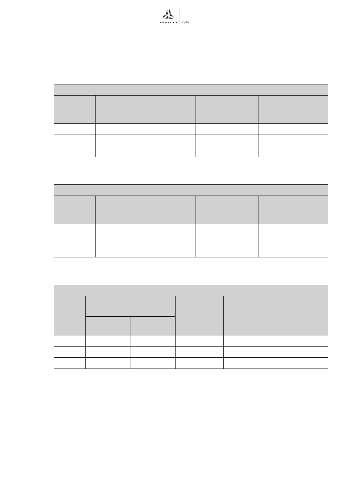
9.1 Specifications for mounting on a machine
9.1.1 Specifications for mounting premo SP line
Through-holes in servo actuator housing of premo SP line
Size Hole circle Ø
[mm]
Quantity x
diameter
[ ] x [mm]
Size 1 68 4 x 5.5 M5 / 12.9 9.0
Size 2 85 4 x 6.6 M6 / 12.9 15.4
Size 3 120 4 x 9.0 M8 / 12.9 37.3
Tbl-11: Specifications for mounting on a machine, premo SP line
9.1.2 Specifications for mounting premo TP line
Through-holes in servo actuator housing of premo TP line
Size Hole circle Ø
[mm]
Quantity x
diameter
[ ] x [mm]
Size 1 79 8 x 4.5 M4 / 12.9 4.55
Size 2 109 8 x 5.5 M5 / 12.9 9.0
Size 3 135 8 x 5.5 M5 / 12.9 9.0
Tbl-12: Specifications for mounting on a machine, premo TP line
For screw size /
property class
For screw size /
property class
Tightening torque
[Nm]
Tightening torque
[Nm]
9.1.3 Specifications for mounting premo XP line
Through-holes / slotted holes in servo actuator housing of premo XP line
Size Hole circle Ø
[mm]
Through-
Slotted holes
holes
Size 1 70 – 8 x 5.5 M5 /12.9 9.0
Size 2 90 95 8 x 6.6 M6 /12.9 15.4
Size 3 120 120 8 x 9.0 M8 /12.9 37.5
–:= on request
Tbl-13: Specifications for mounting on a machine, premo XP line
Quantity x
diameter
[]x [mm]
For screw size /
property class
Tightening
torque
[Nm]
Revision: 02 4022-D045530 en-26
Page 29
Appendix premo
9.2 Specifications for mounting on the output side
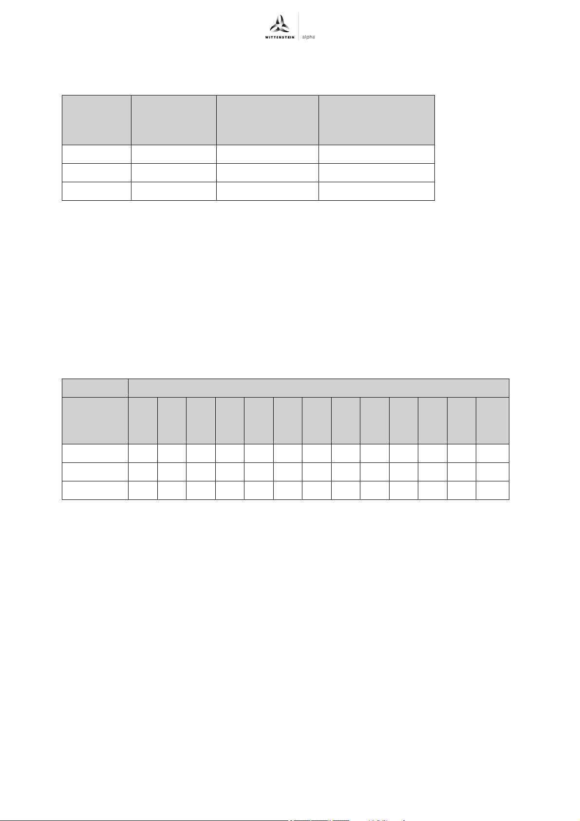
9.2.1 Thread in output flange, premo TP line
Type/Size Hole circle Ø
[mm]
Quantity x Thread
x Depth
[ ] x [mm] x [mm]
Tightening torque
[Nm]
Property class 12.9
Size 1 31.5 8 x M5 x 7 9.0
Size 2 50.0 8 x M6 x 10 15.4
Size 3 63.0 12 x M6 x 12 15.4
Tbl-14: Thread in output flange, premo TP line
9.3 Tightening torques for common thread sizes in general mechanical engineering
The specified tightening torques for set screws and nuts are calculated values and are based on
the following conditions:
- Calculation in accordance with VDI 2230 (February 2003 version)
- Friction value for thread and contact surfaces µ=0.10
- Utilization of the yield stress 90%
- Torque tools type II classes A and D in accordance with ISO 6789
The settings are values rounded to usual commercial scale gradations or setting possibilities.
Use the exact values in this table to set your tools.
Tightening torque [Nm] with thread
Property
M3 M4 M5 M6 M8 M10 M12 M14 M16 M18 M20 M22 M24
class
screw / nut
8.8 / 8 1.15 2.64 5.2 9.0 21.5 42.5 73.5 118 180 258 362 495 625
10.9 / 10 1.68 3.88 7.6 13.2 32.0 62.5 108 173 264 368 520 700 890
12.9 / 12 1.97 4.55 9.0 15.4 37.5 73.5 126 202 310 430 605 820 1040
Tbl-15: Tightening torques for set screws and nuts
en-27 4022-D045530 Revision: 02
Page 30

premo Appendix
9.4 Technical specifications
9.4.1 Motor specifications, premo 320 V
This chapter gives you the technical data of the engine being used. The complete technical data of
the servo actuators can be found in the data sheet of the actuator. The permissible output
specifications of the actuator are influenced by the gearbox and lubricant being used. We would be
glad to provide you with the data sheet, please contact us at: [email protected]
Ordering code PxG xXXx-xxxxxxx-xxxxxxxxx-xxx (XX = stator)
Unit Stator1CStator2CStator1DStator2DStator1FStator
3F
Operating voltage U
Torque constant K
Voltage constant K
D
t
e
Ambient temperature
θ
u
Max. winding
temperature θ
max
Heat transfer
resistance R
th
Thermal time
constants τ
Maximum power P
Maximum torque T
Maximum current I
th
max
max
max
Continuous stall
torque T
0
Continuous stall
current I
No-load speed n
0
0
Connection resistance
R
tt
Connection inductance
L
tt
Electrical time
constant τ
e
V
DC
Nm/A
eff
V
/krpm 21.0 23.7 25.0 31.6 31.1 32.5
eff
320 320 320 320 320 320
0.35 0.39 0.41 0.52 0.51 0.54
°C 40 40 40 40 40 40
°C 140 140 140 140 140 140
K/W 1.19 0.94 0.98 0.81 0.71 0.54
min 12.0 15.7 13.0 17.4 24.0 33.2
kW 0.90 1.88 1.38 2.49 2.75 8.98
Nm 1.40 2.84 2.76 5.53 6.09 16.7
A
eff
4.36 7.74 7.71 12.0 13.3 34.4
Nm 0.60 1.17 1.09 2.11 2.46 6.38
A
eff
1.73 2.96 2.74 4.04 4.80 12.2
rpm 10530 9330 8855 7023 7166 6908
Ohm 15.1 5.70 7.48 3.72 3.23 0.53
mH 10.4 6.12 10.2 7.43 6.97 2.25
ms 0.69 1.08 1.36 2.00 2.16 4.25
Pole pair number p 444444
Moment of inertia
kgcm
2
0.22 0.35 0.46 0.83 1.57 4.13
without brake J
Moment of inertia with
kgcm
2
0.23 0.45 0.52 1.08 1.68 5.34
brake J
Tbl-16: Motor specifications, premo 320 V
Revision: 02 4022-D045530 en-28
Page 31

Appendix premo
9.4.2 Motor specifications, premo 560 V
This chapter gives you the technical data of the engine being used. The complete technical data of
the servo actuators can be found in the data sheet of the actuator. The permissible output
specifications of the actuator are influenced by the gearbox and lubricant being used. We would be
glad to provide you with the data sheet, please contact us at: [email protected]
Ordering code PxG xXXx-xxxxxxx-xxxxxxxxx-xxx (XX = stator)
Unit Stator1CStator2CStator1DStator2DStator1FStator
3F
1)
Operating voltage U
Torque constant K
Voltage constant K
D
t
e
Ambient temperature
θ
u
Max. winding
temperature θ
max
Heat transfer
resistance R
th
Thermal time
constants τ
Maximum power P
Maximum torque T
Maximum current I
th
max
max
max
Continuous stall
torque T
0
Continuous stall
current I
No-load speed n
0
0
Connection resistance
R
tt
Connection
inductance L
tt
Electrical time
constant τ
e
Pole pair number p 444444
Moment of inertia
without brake J
Moment of inertia with
brake J
1)
Operation of the actuator is reliable up to a maximum nominal intermediate circuit voltage of
V
DC
Nm/A
eff
V
/krpm 36.4 41.1 43.3 54.8 53.8 56.3
eff
560 560 560 560 560 560
0.60 0.68 0.72 0.91 0.89 0.93
°C 40 40 40 40 40 40
°C 140 140 140 140 140 140
K/W 1.19 0.94 0.98 0.81 0.71 0.54
min 12.0 15.7 13.0 17.4 24.0 33.2
kW 0.90 1.88 1.38 2.49 2.75 8.98
Nm 1.40 2.84 2.76 5.53 6.09 16.7
A
eff
2.52 4.47 4.45 6.94 7.70 19.8
Nm 0.60 1.17 1.09 2.11 2.46 6.38
A
eff
1.00 1.71 1.58 2.33 2.77 7.05
rpm 10530 9330 8855 7023 7166 6908
Ohm 45.3 17.1 22.4 11.2 9.69 1.59
mH 31.3 18.4 30.6 22.3 20.9 6.75
ms 0.69 1.08 1.36 2.00 2.16 4.25
2
kgcm
kgcm
2
0.22 0.35 0.46 0.83 1.57 4.13
0.23 0.45 0.52 1.08 1.68 5.34
750 V.
Tbl-17: Motor specifications, premo 560 V
en-29 4022-D045530 Revision: 02
Page 32
premo Appendix
9.4.3 Technical specifications for resolver
Resolver
Ordering code PxG xxxx-xxxxxxx-xRxxxxxxx-xxx
Size Size 15
Type TS2620N21E11
Pole pair number 1
Input voltage 7V
10kHz
eff
Transmission ratio 0,5±5%
Fault ± 10'max
Zero voltage 20mV
eff
max
Phase shift 0° nominal
Impedance ZR0 70 + j 100 ohm
Impedance ZS0 180 + j 300 ohm
Impedance ZSS 175 + j 257 ohm
Max. operating temperature 155 °C
Tbl-18: Technical specifications for resolver
9.4.4 Technical specifications of Hiperface absolute encoder Singleturn
Hiperface absolute encoder Singleturn
Ordering code PxG xxxx-xxxxxxx-xNxxxxxxx-xxx
Type SKS36S
Operating voltage 7-12 V
Interface Hiperface
Number of SinCos periods per revolution 128
Resolution per revolution 4096 (12 bit)
Number of Multiturn revolutions –
SIL level SIL2
Tbl-19: Technical specifications of Hiperface absolute encoder Singleturn
9.4.5 Technical specifications of Hiperface absolute encoder Multiturn
Hiperface absolute encoder Multiturn
Ordering code PxG xxxx-xxxxxxx-xKxxxxxxx-xxx
Type SKM36S
Operating voltage 7-12 V
Interface Hiperface
Number of SinCos periods per revolution 128
Resolution per revolution 4096 (12 bit)
Number of Multiturn revolutions 4096 (12 bit)
SIL level SIL2
Tbl-20: Technical specifications of Hiperface absolute encoder Multiturn
Revision: 02 4022-D045530 en-30
Page 33

Appendix premo
9.4.6 Technical specifications of Hiperface DSL absolute encoder Singleturn
Hiperface DSL absolute encoder Singleturn
Ordering code PxG xxxx-xxxxxxx-xGxxxxxxx-xxx
Type EKS36
Operating voltage 7-12 V
Interface Hiperface DSL
Number of SinCos periods per revolution –
Resolution per revolution 1.048.576 (20 bit)
Number of Multiturn revolutions –
SIL level SIL2
Tbl-21: Technical specifications of Hiperface DSL absolute encoder Singleturn
9.4.7 Technical specifications of Hiperface DSL absolute encoder Multiturn
Hiperface DSL absolute encoder Multiturn
Ordering code PxG xxxx-xxxxxxx-xHxxxxxxx-xxx
Type EKM36
Operating voltage 7-12 V
Interface Hiperface DSL
Number of SinCos periods per revolution –
Resolution per revolution 1.048.576 (20 bit)
Number of Multiturn revolutions 4096 (12 bit)
SIL level SIL2
Tbl-22: Technical specifications of Hiperface DSL absolute encoder Multiturn
9.4.8 Technical specifications of EnDat 2.1 absolute encoder Singleturn
EnDat 2.1 absolute encoder Singleturn
Ordering code PxG xxxx-xxxxxxx-xSxxxxxxx-xxx
Type ECN 1113
Operating voltage 3.6-14 V
Interface Endat 2.2 / EnDat01
Number of SinCos periods per revolution 512
Resolution per revolution 8192 (13 bit)
Number of Multiturn revolutions –
SIL level –
Tbl-23: Technical specifications of EnDat 2.1 absolute encoder Singleturn
en-31 4022-D045530 Revision: 02
Page 34
premo Appendix
9.4.9 Technical specifications of EnDat 2.1 absolute encoder Multiturn
EnDat 2.1 absolute encoder Multiturn
Ordering code PxG xxxx-xxxxxxx-xMxxxxxxx-xxx
Type EQN 1125
Operating voltage 3.6-14 V
Interface Endat 2.2 / EnDat01
Number of SinCos periods per revolution 512
Resolution per revolution 8192 (13 bit)
Number of Multiturn revolutions 4096 (12 bit)
SIL level –
Tbl-24: Technical specifications of EnDat 2.1 absolute encoder Multiturn
9.4.10 Technical specifications of EnDat 2.2 absolute encoder Singleturn
EnDat 2.2 absolute encoder Singleturn
Ordering code PxG xxxx-xxxxxxx-xFxxxxxxx-xxx
Type ECN 1123
Operating voltage 3.6-14 V
Interface Endat 2.2 / EnDat22
Number of SinCos periods per revolution –
Resolution per revolution 8.388.608 (23 bit)
Number of Multiturn revolutions –
SIL level SIL2
Tbl-25: Technical specifications of EnDat 2.2 absolute encoder Singleturn
9.4.11 Technical specifications of EnDat 2.2 absolute encoder Multiturn
EnDat 2.2 absolute encoder Multiturn
Ordering code PxG xxxx-xxxxxxx-xWxxxxxxx-xxx
Type EQN 1135
Operating voltage 3.6-14 V
Interface Endat 2.2 / EnDat22
Number of SinCos periods per revolution –
Resolution per revolution 8.388.608 (23 bit)
Number of Multiturn revolutions 4096 (12 bit)
SIL level SIL2
Tbl-26: Technical specifications of EnDat 2.2 absolute encoder Multiturn
Revision: 02 4022-D045530 en-32
Page 35

Appendix premo
9.4.12 Technical specifications of DRIVE-CLiQ absolute encoder Singleturn
DRIVE-CLiQ absolute encoder Singleturn
Ordering code PxG xxxx-xxxxxxx-xLxxxxxxx-xxx
Type ECN 1324S
Operating voltage 10 - 36 V
Interface DRIVE-CLiQ
Number of SinCos periods per revolution –
Resolution per revolution 16.777.216 (24 bit)
Number of Multiturn revolutions –
SIL level SIL2
Tbl-27: Technical specifications of DRIVE-CLiQ absolute encoder Singleturn
9.4.13 Technical specifications of DRIVE-CLiQ absolute encoder Multiturn
DRIVE-CLiQ absolute encoder Multiturn
Ordering code PxG xxxx-xxxxxxx-xDxxxxxxx-xxx
Type EQN 1336S
Operating voltage 10 - 36 V
Interface DRIVE-CLiQ
Number of SinCos periods per revolution –
Resolution per revolution 16.777.216 (24 bit)
Number of Multiturn revolutions 4096 (12 bit)
SIL level SIL2
Tbl-28: Technical specifications of DRIVE-CLiQ absolute encoder Multiturn
9.4.14 Technical specifications of Hiperface absolute encoder Singleturn (compatible with Rockwell)
Hiperface absolute encoder Singleturn (compatible with Rockwell)
Ordering code PxG xxxx-xxxxxxx-xExxxxxxx-xxx
Type SKS36S
Operating voltage 7 – 12 V
Interface Hiperface
Number of SinCos periods per revolution 128
Resolution per revolution 4096 (12 bit)
Number of Multiturn revolutions –
SIL level SIL2
Tbl-29: Technical specifications of Hiperface absolute encoder Singleturn (compatible with
Rockwell)
en-33 4022-D045530 Revision: 02
Page 36
premo Appendix
9.4.15 Technical specifications of Hiperface absolute encoder Multiturn (compatible with Rockwell)
Hiperface absolute encoder Multiturn (compatible with Rockwell)
Ordering code PxG xxxx-xxxxxxx-xVxxxxxxx-xxx
Type SKM36S
Operating voltage 7 – 12 V
Interface Hiperface
Number of SinCos periods per revolution 128
Resolution per revolution 4096 (12 bit)
Number of Multiturn revolutions 4096 (12 bit)
SIL level SIL2
Tbl-30: Technical specifications of Hiperface absolute encoder Multiturn (compatible with
Rockwell)
9.4.16 Technical specifications of Hiperface DSL absolute encoder Singleturn (compatible with Rockwell)
Hiperface DSL absolute encoder Singleturn (compatible with Rockwell)
Ordering code PxG xxxx-xxxxxxx-xJxxxxxxx-xxx
Type EKS36
Operating voltage 7-12 V
Interface HiperfaceDSL
Number of SinCos periods per revolution –
Resolution per revolution 1.048.576 (20 bit)
Number of Multiturn revolutions –
SIL level SIL2
Tbl-31: Technical specifications of Hiperface DSL absolute encoder Singleturn (compatible with
Rockwell)
9.4.17 Technical specifications of Hiperface DSL absolute encoder Multiturn (compatible with Rockwell)
Hiperface DSL absolute encoder Multiturn (compatible with Rockwell)
Ordering code PxG xxxx-xxxxxxx-xPxxxxxxx-xxx
Type EKM36
Operating voltage 7-12 V
Interface HiperfaceDSL
Number of SinCos periods per revolution –
Resolution per revolution 1.048.576 (20 bit)
Number of Multiturn revolutions 4096 (12 bit)
SIL level SIL2
Tbl-32: Technical specifications of Hiperface DSL absolute encoder Multiturn (compatible with
Rockwell)
Revision: 02 4022-D045530 en-34
Page 37

Appendix premo
9.4.18 Technical specifications Heidenhain Incremental
Heidenhain Incremental
Ordering code PxG xxxx-xxxxxxx-xIxxxxxxx-xxx
Type ERN 1185
Operating voltage 5 V
Interface Incremental interface
Number of SinCos periods per revolution 2048
Resolution per revolution –
Number of Multiturn revolutions –
SIL level –
Tbl-33: Technical specifications Heidenhain Incremental
9.4.19 Technical specifications temperature sensors KTY and PT 1000
Type KTY 84-130 PT 1000
Ordering
code:
Temperature
[°C]
-30 0.391 882.11
-20 0.424 921.57
-10 0.460 960.86
0 0.498 1000
10 0.538 1039.03
20 0.581 1077.94
25 0.603 1097.4
30 0.626 1116.73
40 0.672 1155.41
50 0.722 1193.97
60 0.773 1232.42
70 0.826 1270.75
PxG xxxx-xxxxxxx-
xxKxxxxxx-xxx
Resistance, type
[kohm]
PxG xxxx-xxxxxxx-
Resistance, type
xxTxxxxxx-xxx
[Ohm]
80 0.882 1308.97
90 0.940 1347.07
100 1.000 1385.06
110 1.062 1422.93
120 1.127 1460.68
130 1.194 1498.32
140 1.262 1535.84
150 1.334 1573.25
160 1.407 1610.54
en-35 4022-D045530 Revision: 02
Page 38
premo Appendix
Type KTY 84-130 PT 1000
Ordering
code:
Temperature
[°C]
PxG xxxx-xxxxxxx-
xxKxxxxxx-xxx
Resistance, type
[kohm]
PxG xxxx-xxxxxxx-
xxTxxxxxx-xxx
Resistance, type
[Ohm]
170 1.482 1647.72
180 1.560 1684.78
190 1.640 1721.73
200 1.722 1758.56
Tbl-34: Technical specifications of KTY, NTC and PT 1000 temperature sensors
9.4.20 Technical specifications of PTC temperature sensor
PTC STM 160
Ordering code: PxG xxxx-xxxxxxx-xxPxxxxxx-xxx
Deactivation in case of fault
Characteristic line in accordance with DIN 44081/44082
Temperature [°C] Resistance [ohm]
< 140 20 - 250
140 - 155 250 - 550
155 - 165 550 - 1330
165 - 175 1330 - 4000
> 175 > 4000
Tbl-35: Technical specifications of PTC temperature sensor
Revision: 02 4022-D045530 en-36
Page 39
Appendix premo
9.4.21 Technical specifications of premo brake
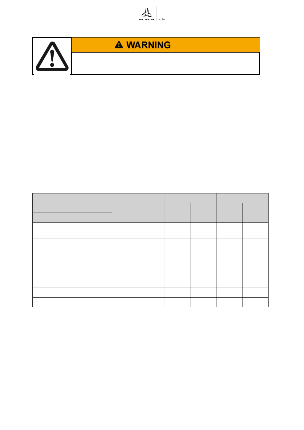
The holding brake used is not a safety brake and is not suitable for
personal protection or as a service brake.
The brakes installed in the actuators work on the basis of a permanent magnetic circuit. When the
power is off, the brake pads make contact and a holding torque is built up. When the power is on
the permanent magnetic field is compensated and the friction surfaces separate without residual
torque.
The brakes used are designed as holding brakes. The intended use is in applications where no
dynamic braking procedures must be initiated by the brakes in fault/free operation.
In emergency stop situations a dynamic braking procedure could be necessary. Observe the
effective torques in the braking procedure for your dimensioning.
The reduction of kinetic energy in dynamic braking procedures increases the abrasive wear on the
brake pads, which can change the magnetic circuit within the brake. This can change opening and
closing times and can result in the brake no longer reaching the specified holding torque or no
longer closing.
For additional information about dynamic braking in emergency stop situations, please contact our
sales department.
Observe the instructions given in Chapter 7.1.1 "Refreshment of holding brake" for fault free
operation.
PxG 1 PxG 2 PxG 3
Ratio 16 – 35 40 – 100 16 – 35 40 – 100 16 – 35 40 – 100
Unit
Static holding
torque at 120°C
Dynamic braking
torque
Supply voltage V DC 24 24 24 24 24 24
Current at rated
rated voltage and
20 °C
Linking time msec ≤ 8 ≤ 10 ≤ 20 ≤ 8 – ≤ 20
Separation time msec ≤ 35 ≤ 18 ≤ 50 ≤ 35 ≤ 60 ≤ 50
The listed opening and closing times are noted without the use of an additional wiring of the brake.
To avoid interfering signals from the switching of the brake, in general an additional wiring, e.g.
in form of a varistor, should be added. Observe the requirements for this of the applied servo
controller manufacturer.
Nm 1.30 0.52 2.34 1.30 7.28 2.34
Nm––––––
A DC 0.46 0.42 0.50 0.46 0.71 0.50
Tbl-36: Technical specifications of premo brake
en-37 4022-D045530 Revision: 02
Page 40
premo Appendix
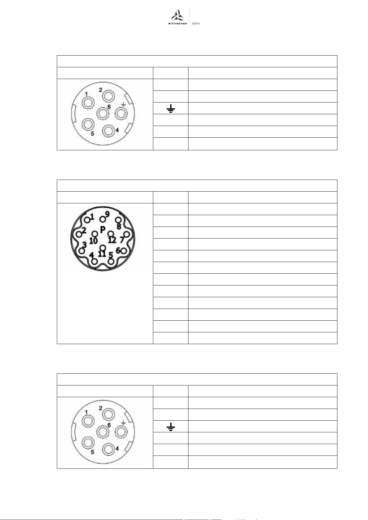
9.4.22 Pin assignment 1 Design with resolver — output (pin assignment 1)
Intercontec mounting socket, series production 923, 6-pin, contact pin Ø 2mm
View of plug side of actuator Pin Function
1W
2U
Earth conductor
4V
5 Brake + (optional)
6 Brake – (optional)
Tbl-37: Design with resolver — output (pin assignment 1)
Option "R" — signal (pin assignment 1)
Intercontec mounting socket, series production 623, 12-pin P, contact pin Ø 1mm
View of plug side of actuator Pin Function
1Cos/S1
2 Cos-low/S3
3Sin/S2
4Sin-low/S4
5Temp +
6Temp -
7 Ref/R1
8 Ref-low/R2
9 Screen
10 n.c.
11 n.c.
12 n.c.
Tbl-38: Option "R" – signal (pin assignment 1)
Design with optical encoder — output (pin assignment 1)
Intercontec mounting socket, series production 923, 6-pin, contact pin Ø 2mm
View of plug side of actuator Pin Function
1U
2V
Earth conductor
4 Brake + (optional)
5 Brake – (optional)
6W
Tbl-39: Design with optical encoder — output (pin assignment 1)
Revision: 02 4022-D045530 en-38
Page 41
Appendix premo
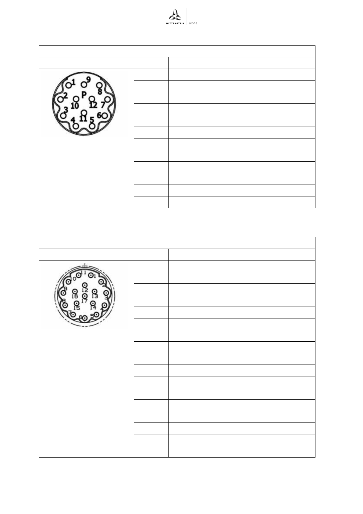
Option "N" and "K" — signal (pin assignment 1)
Intercontec mounting socket, series production 623, 12-pin P, contact pin Ø 1mm
View of plug side of actuator Pin Function
1REFCOS
2 Data +
3 Temp +
4 Temp -
5SIN
6 REFSIN
7 Data -
8COS
9n.c.
10 GND
11 n.c.
12 7 – 12 V
Tbl-40: Option "N" and "K" — signal (pin assignment 1)
Option "S" and "M" — signal (pin assignment 1)
Intercontec mounting socket, series production 623, 17-pin E, contact pin Ø 1mm
View of plug side of actuator Pin Function
1A
2A*
3 data
4n.c.
5clock
6n.c.
7 M- Encoder (0V)
8 Temp +
9 Temp -
10 P- Encoder (U
11 B
)
P
12 B*
13 data*
14 clock*
15 M- Sense (0V- Sense / Sensor 0V)
16 P- Sense (5V-Sense / Sensor U
)
P
17 n.c.
Tbl-41: Option "S" and "M" — signal (pin assignment 1)
en-39 4022-D045530 Revision: 02
Page 42
premo Appendix
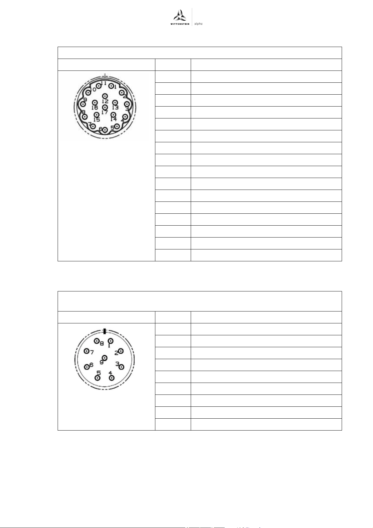
Option "F" and "W" — signal (pin assignment 1)
Intercontec mounting socket, series production 623, 17-pin E, contact pin Ø 1mm
View of plug side of actuator Pin Function
1n.c.
2n.c.
3 data
4n.c.
5clock
6n.c.
7 M- Encoder (0V)
8n.c.
9n.c.
10 P- Encoder (U
)
P
11 n.c.
12 n.c.
13 data*
14 clock*
15 M- Sense (0V- Sense / Sensor 0V)
16 P- Sense (5V-Sense / Sensor U
Tbl-42: Option "F" and "W" — signal (pin assignment 1)
)
P
Option "L" and "D" — signal (pin assignment 1)
Intercontec mounting socket, series production 623, 8+1-pin E, contact pin 8 x Ø 1mm + 1 x
Ø 2mm
View of plug side of actuator Pin Function
1TXP
2TXN
3n.c.
40 V
5RXP
6RXN
7n.c.
8Up
9n.c.
Tbl-43: Option "L" and "D" — signal (pin assignment 1)
Revision: 02 4022-D045530 en-40
Page 43
Appendix premo
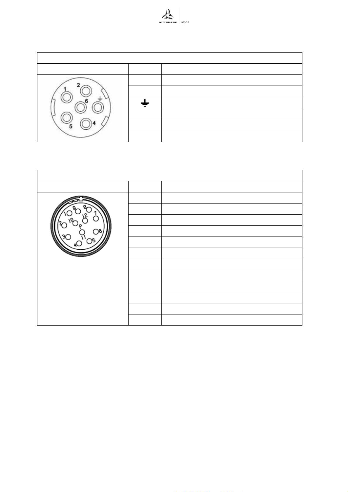
9.4.23 Pin assignment 2 Design with resolver and EnDat encoder — output (pin assignment 2)
Intercontec mounting socket, series production 923, 6-pin, contact pin Ø 2mm
View of plug side of actuator Pin Function
1U
2V
Earth conductor
4 Brake + (optional)
5 Brake – (optional)
6W
Tbl-44: Design with resolver and EnDat encoder — output size 1 (pin assignment 2)
Option "R" — signal (pin assignment 2)
Intercontec mounting socket, series production 623, 12-pin P, 20° coded, contact pin Ø 1mm
View of plug side of actuator Pin Function
1Sin/S2
2Sin-low/S4
3n.c.
4n.c.
5n.c.
6n.c.
7Ref-low/R2
8 Temp +
9Temp –
10 Ref/R1
11 Cos/S1
12 Cos-low/S3
Tbl-45: Option "R" — signal (pin assignment 2)
en-41 4022-D045530 Revision: 02
Page 44
premo Appendix
Option "S" and "M" — signal (pin assignment 2)
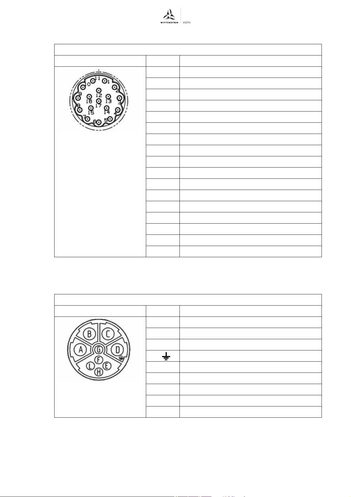
Intercontec mounting socket, series production 623, 17-pin E, contact pin Ø 1mm
View of plug side of actuator Pin Function
1A
2A*
3 data
4n.c.
5clock
6n.c.
7 M- Encoder (0V)
8Temp +
9Temp -
9.4.24 Pin assignment 4 Design with resolver, EnDat- and Hiperface encoder — output (pin assignment 4)
Intercontec mounting socket, series production 923, 9-pin E, contact pin 4x2mm + 5x1mm
View of plug side of actuator Pin Function
10 P- Encoder (U
11 B
12 B*
13 data*
14 clock*
15 M- Sense (0V- Sense / Sensor 0V)
16 P- Sense (5V-Sense / Sensor U
17 n.c.
Tbl-46: Option "S" and "M" — signal (pin assignment 2)
AU
BV
)
P
)
P
CW
D ( ) Earth conductor
ETemp +
F Brake + (optional)
G Brake – (optional)
HTemp -
Ln.c.
Tbl-47: Design with resolver, EnDat- and Hiperface encoder — output (pin assignment 4)
Revision: 02 4022-D045530 en-42
Page 45
Appendix premo
Option "R" — signal (pin assignment 4)
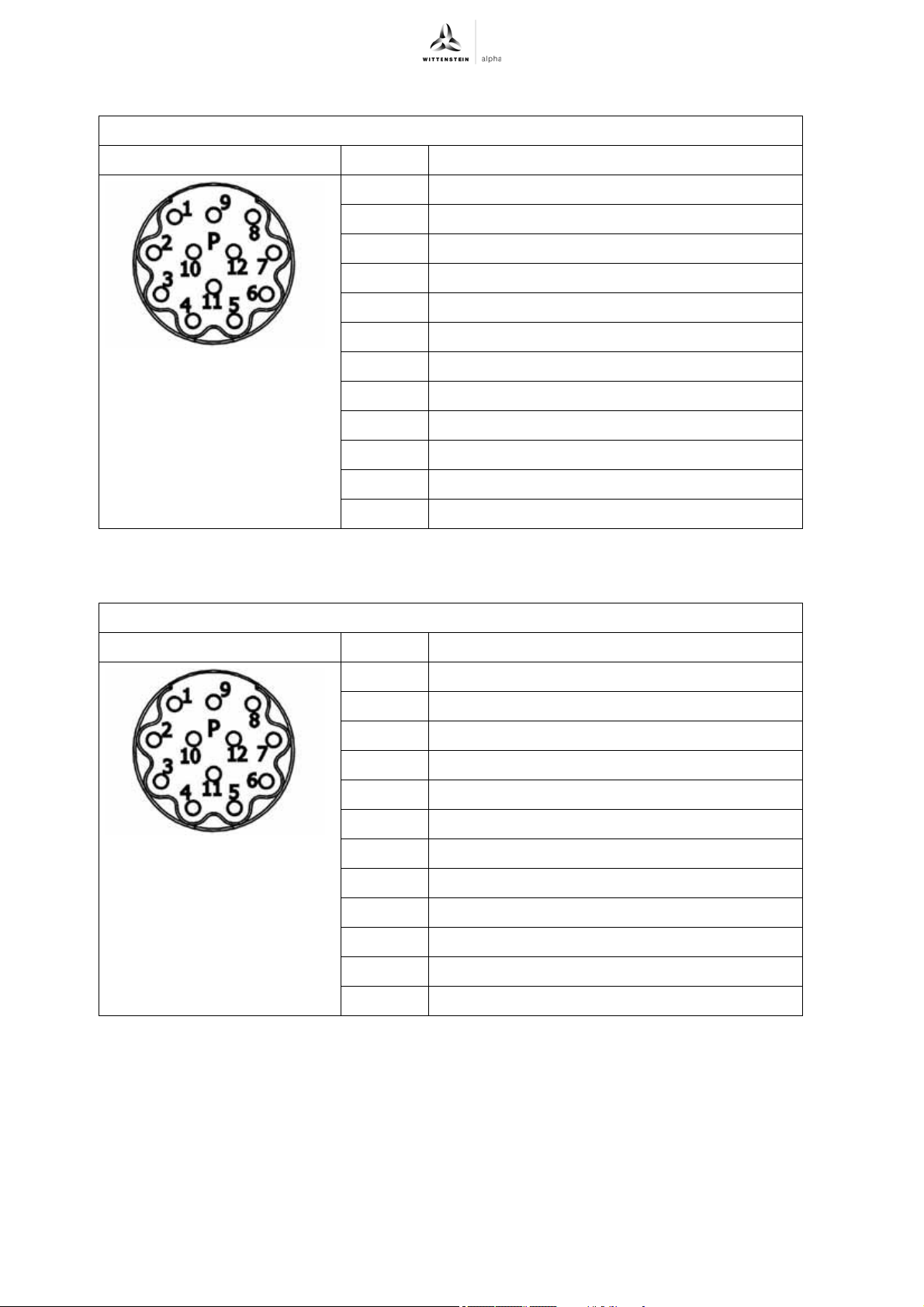
Intercontec mounting socket, series production 623, 12-pin P, contact pin Ø 1mm
View of plug side of actuator Pin Function
1Cos/S1
2 Cos-low/S3
3Sin/S2
4Sin-low/S4
5n.c.
6n.c.
7 Ref/R1
8Ref-low/R2
9Screen
10 n.c.
11 n.c.
12 n.c.
Tbl-48: Option "R" — signal (pin assignment 4)
Option "N" and "K" — signal (pin assignment 4)
Intercontec mounting socket, series production 623, 12-pin P, contact pin Ø 1mm
View of plug side of actuator Pin Function
1REFCOS
2 Data +
3n.c.
4n.c.
5SIN
6 REFSIN
7 Data -
8COS
9n.c.
10 GND
11 n.c.
12 7 – 12 V
Tbl-49: Option "N" and "K" — signal (pin assignment 4)
en-43 4022-D045530 Revision: 02
Page 46
premo Appendix
Option "S" and "M" — signal (pin assignment 4)
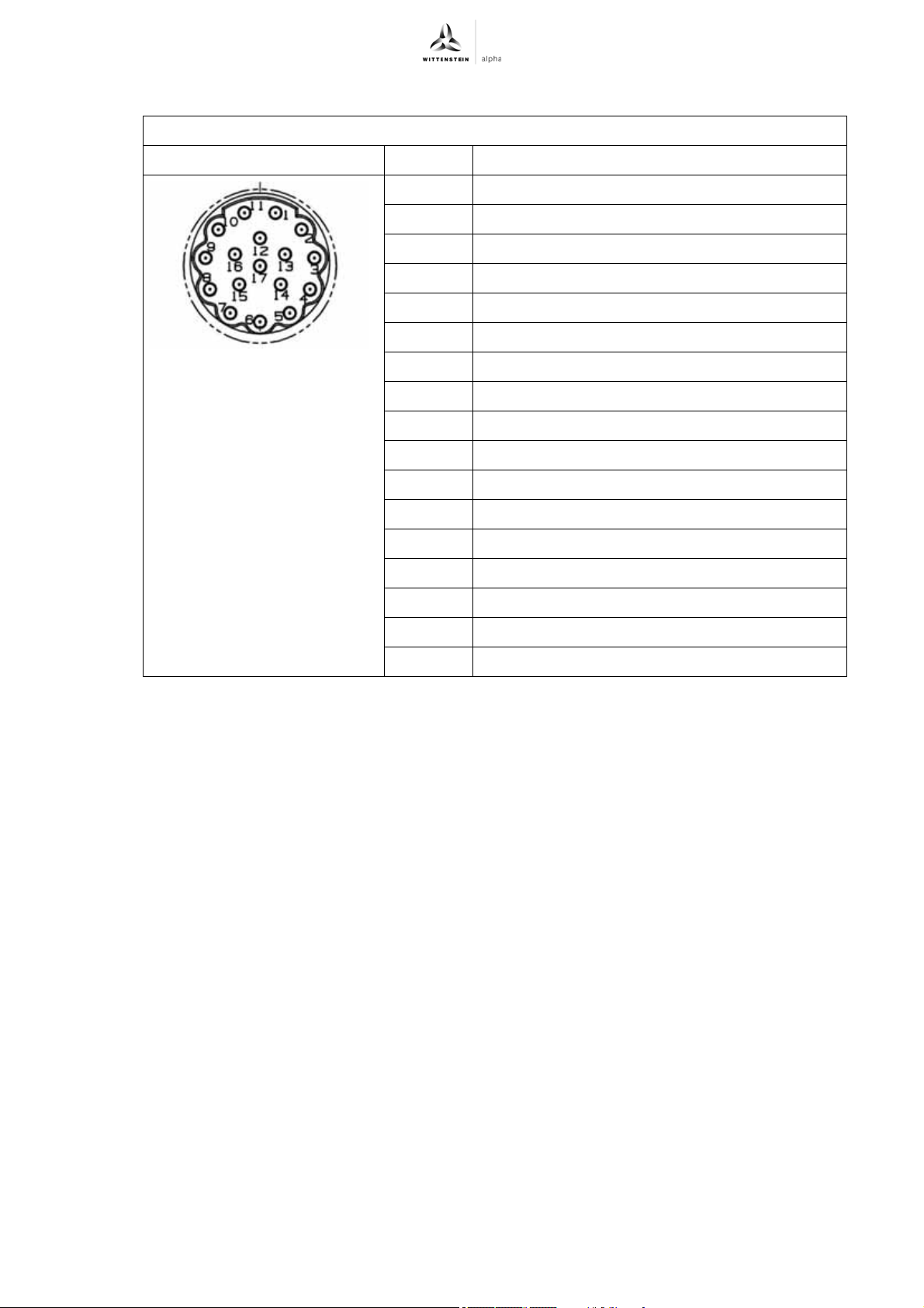
Intercontec mounting socket, series production 623, 17-pin E, contact pin Ø 1mm
View of plug side of actuator Pin Function
1A
2A*
3 data
4n.c.
5clock
6n.c.
7 M- Encoder (0V)
8n.c.
9n.c.
10 P- Encoder (U
11 B
12 B*
13 data*
14 clock*
15 M- Sense (0V- Sense / Sensor 0V)
16 P- Sense (5V-Sense / Sensor U
17 n.c.
Tbl-50: Option "S" and "M" — signal (pin assignment 4)
)
P
)
P
Revision: 02 4022-D045530 en-44
Page 47
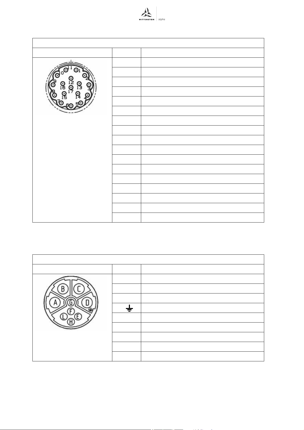
Appendix premo
Option "F" and "W" — signal (pin assignment 4)
Intercontec mounting socket, series production 623, 17-pin E, contact pin Ø 1mm
View of plug side of actuator Pin Function
1n.c.
2n.c.
3 data
4n.c.
5clock
6n.c.
7 M- Encoder (0V)
8n.c.
9n.c.
9.4.25 Pin assignment 5 Design with optical encoder — output (pin assignment 5)
Intercontec mounting socket, series production 923, 9-pin E, contact pin 4x2mm + 5x1mm
View of plug side of actuator Pin Function
10 P- Encoder (U
11 n.c.
12 n.c.
13 data*
14 clock*
15 M- Sense (0V- Sense / Sensor 0V)
16 P- Sense (5V-Sense / Sensor U
17 n.c.
Tbl-51: Option "F" and "W" — signal (pin assignment 4)
AU
BV
)
P
)
P
CW
D ( ) Earth conductor
En.c.
F Brake + (optional)
G Brake – (optional)
Hn.c.
Ln.c.
Tbl-52: Design with optical encoder — output (pin assignment 5)
en-45 4022-D045530 Revision: 02
Page 48
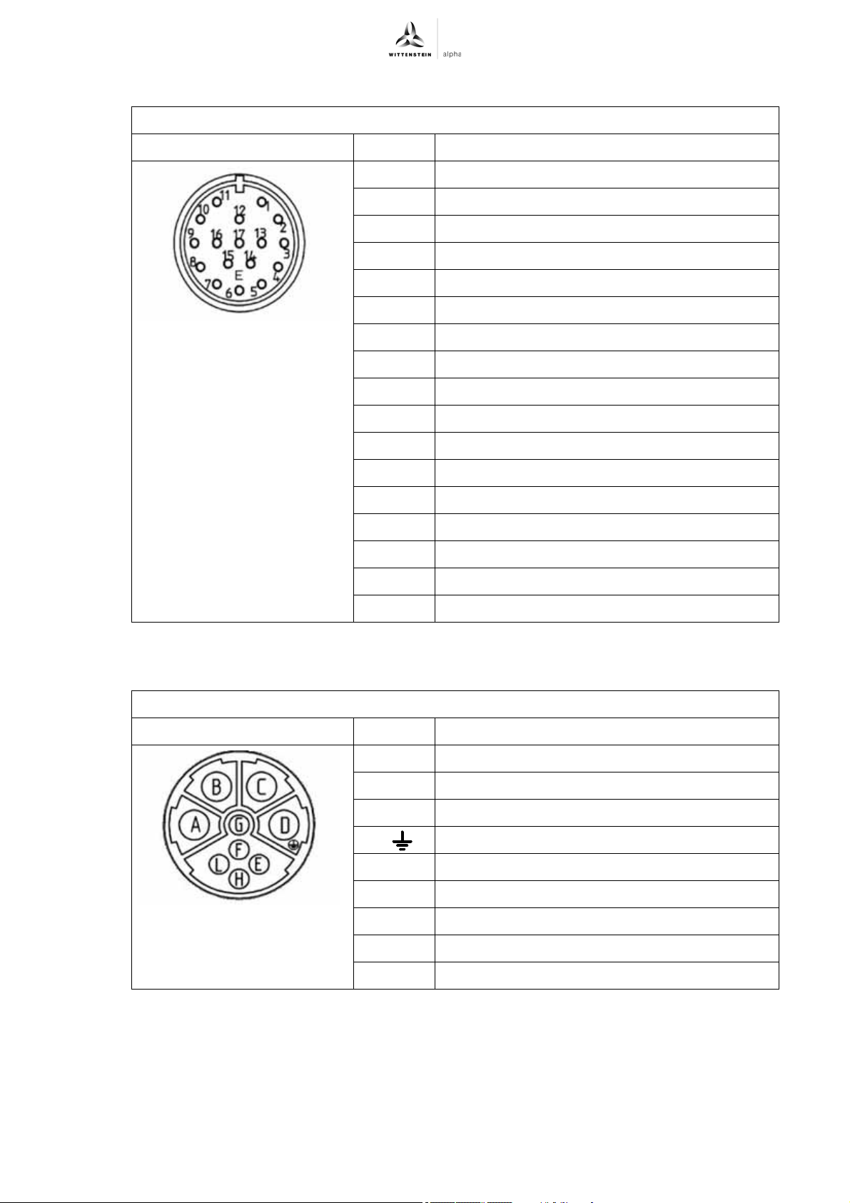
premo Appendix
Option "E" and "V" — signal (pin assignment 5)
Intercontec mounting socket, series production 623, 17-pin E, contact pin Ø 1mm
View of plug side of actuator Pin Function
1 SIN +
2 SIN -
3COS +
4COS -
5Data +
6Data -
7n.c.
8n.c.
9n.c.
10 n.c.
11 +9 VDC
12 Common
13 Temp +
14 Temp -
15 n.c.
16 n.c.
17 n.c.
Tbl-53: Option "E" and "V" — signal (pin assignment 5)
Option "J" and "P" — output/signal (pin assignment 5)
Intercontec mounting socket, series production 923, 9-pin E, contact pin 4x2mm + 5x1mm
View of plug side of actuator Pin Function
AU
BV
CW
D ( ) Earth conductor
E Us / DSL +
F Brake + (optional)
G Brake – (optional)
H GND / DSL -
Ln.c.
Tbl-54: Option "J" and "P" — output/signal (pin assignment 5)
Revision: 02 4022-D045530 en-46
Page 49
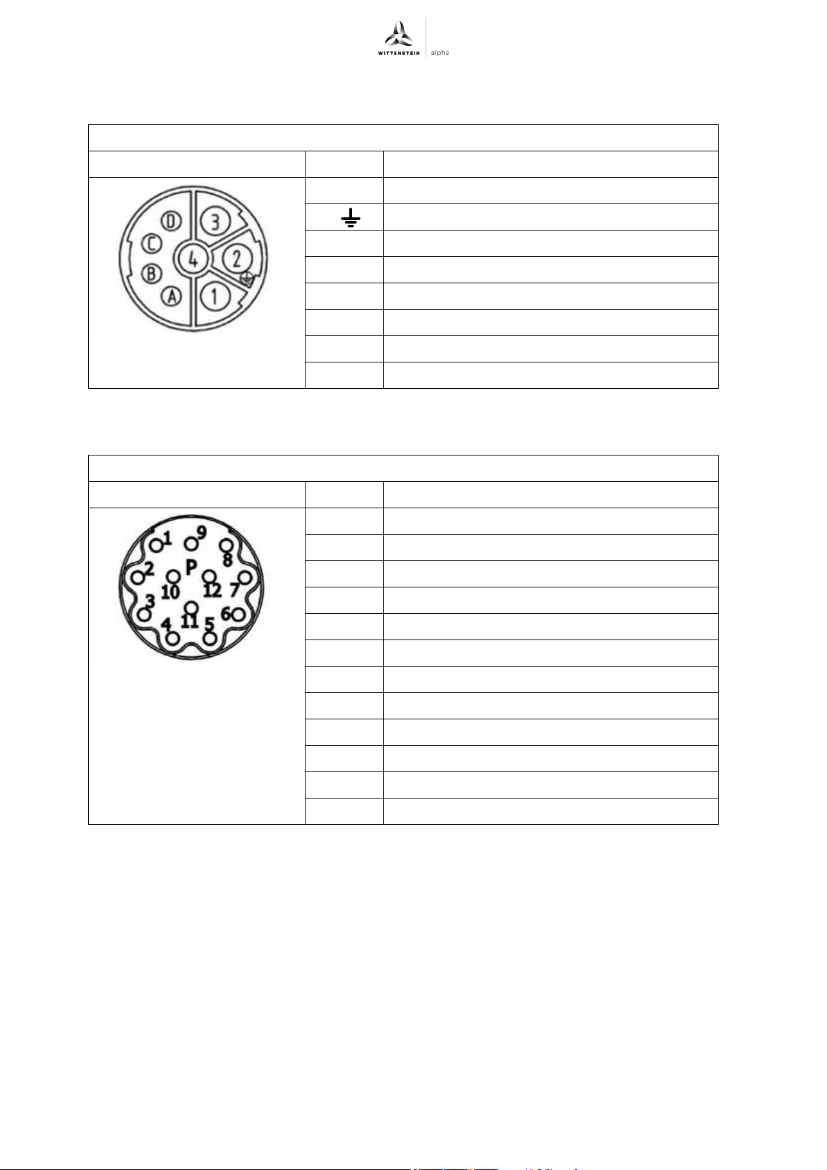
Appendix premo
9.4.26 Pin assignment 6 Design with resolver and optical encoder — output (pin assignment 6)
Intercontec mounting socket, series production 923, 8-pin E, contact pin 4x2mm + 4x1mm
View of plug side of actuator Pin Function
1U
2 ( ) Earth conductor
3W
4V
A Temp +
B Temp -
C Brake + (optional)
D Brake - (optional)
Tbl-55: Design with resolver and optical encoder — output (pin assignment 6)
Option "R" — signal (pin assignment 6)
Intercontec mounting socket, series production 623, 12-pin P, contact pin Ø 1mm
View of plug side of actuator Pin Function
1n.c.
2n.c.
3Sin-low/S4
4Cos/S1
5Ref-low/R2
6n.c.
7Sin/S2
8 Cos-low/S3
9 Ref/R1
10 n.c.
11 n.c.
12 n.c.
Tbl-56: Option "R" — signal (pin assignment 6)
en-47 4022-D045530 Revision: 02
Page 50
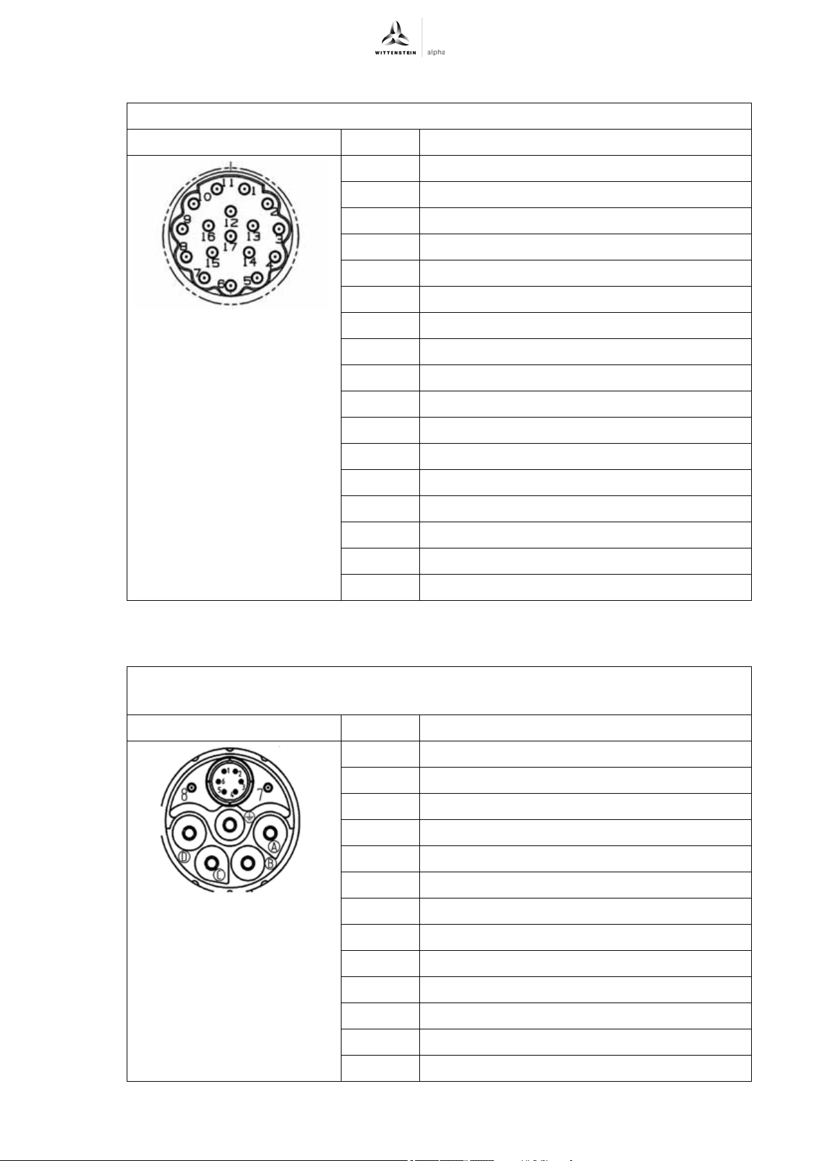
premo Appendix
Option "S" and "M" — signal (pin assignment 6)
Intercontec mounting socket, series production 623, 17-pin E, contact pin Ø 1mm
View of plug side of actuator Pin Function
1 P- Sense (5V-Sense / Sensor U
)
P
2n.c.
3n.c.
4 M- Sense (0V- Sense / Sensor 0V)
5n.c.
6n.c.
7 P- Encoder (U
)
P
8clock
9 clock*
10 M- Encoder (0V)
11 n.c.
12 B
13 B*
14 data
15 A
16 A*
17 data*
Tbl-57: Option "S" and "M" — signal (pin assignment 6)
Option "F" and "W" — output/signal (pin assignment 6)
Intercontec mounting socket, series production 723, 13-pin E,
Contact pin 5 x Ø 2mm + 2 x Ø 1mm + 6 x Ø 0.34mm
View of plug side of actuator Pin Function
1 P- Encoder (U
2 M- Encoder (0V)
3 data
4data*
5clock
6 clock*
7 Brake + (optional)
8 Brake - (optional)
AU
)
P
BV
CW
Dn.c.
E Earth conductor
Tbl-58: Option "F" and "W" — output/signal (pin assignment 6)
Revision: 02 4022-D045530 en-48
Page 51
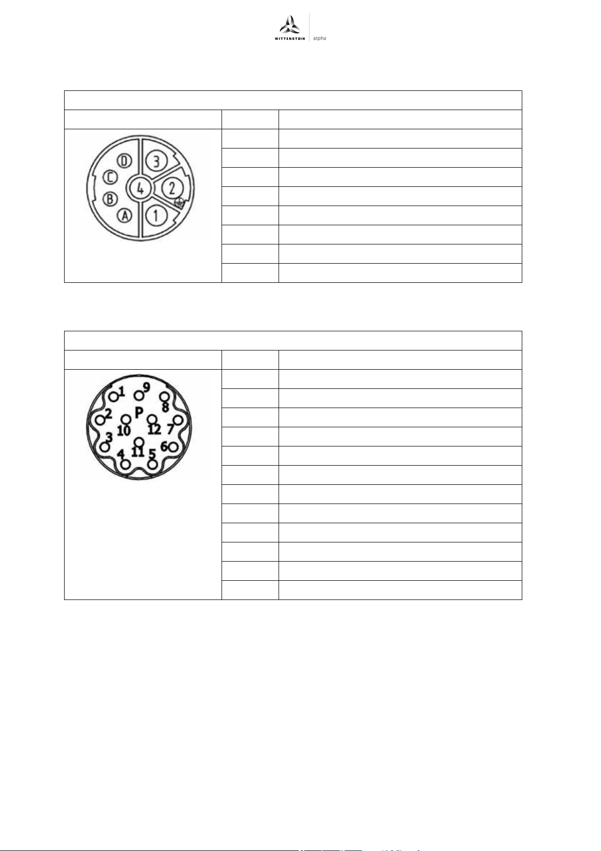
Appendix premo
9.4.27 Pin assignment 8 Design with optical encoder — output (pin assignment 8)
Intercontec mounting socket, series production 923, 8-pin E, contact pin 4x2mm + 4x1mm
View of plug side of actuator Pin Function
A Brake + (optional)
B Brake - (optional)
C Temp +
D Temp -
1W
2 Earth conductor
3U
4V
Tbl-59: Design with optical encoder — output (pin assignment 8)
Option "N" and "K" — signal (pin assignment 8)
Intercontec mounting socket, series production 623, 12-pin P, contact pin Ø 1mm
View of plug side of actuator Pin Function
1REFCOS
2 Data +
3n.c.
4n.c.
5SIN
6 REFSIN
7 Data -
8COS
9n.c.
10 GND
11 n.c.
12 7 – 12 V
Tbl-60: Option "N" and "K" — signal (pin assignment 8)
en-49 4022-D045530 Revision: 02
Page 52
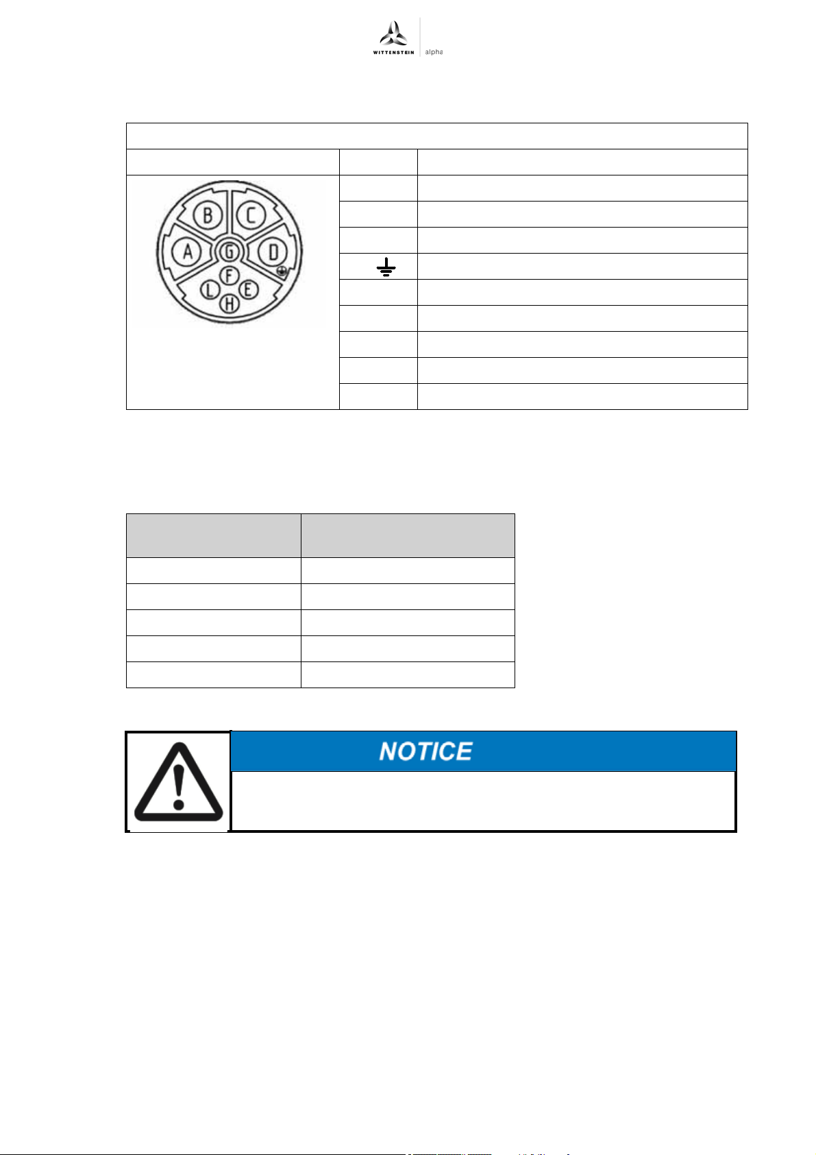
premo Appendix
9.4.28 Pin assignment 9 Option "G" and "H" — output/signal (pin assignment 9)
Intercontec mounting socket, series production 923, 9-pin E, contact pin 4x2mm + 5x1mm
View of plug side of actuator Pin Function
AU
BV
CW
D ( ) Earth conductor
E GND / DSL -
F Screen
G Brake + (optional)
H Us / DSL +
L Brake - (optional)
Tbl-61: Option "G" and "H" — output/signal (pin assignment 9)
9.4.29 Cable setup / Cable cross-section
For ambient temperatures up to +40°C, the following applies for cables according to to DIN EN
60204-1, Table 6 for installation type C:
Continuous stall
current
0 – 15 Aeff 4 x 1.5 mm
15 – 21 Aeff 4 x 2.5 mm2 & 2 x 1 mm
21 – 36 Aeff 4 x 6 mm2 & 2 x 1.5 mm
36 – 50 Aeff 4 x 10 mm2 & 2 x 1.5 mm2
50 – 66 Aeff 4 x 16 mm
Tbl-62: Cable setup / Cable cross-section
The maximum cable length must not exceed 50 m.
Cable
2
& 2 x 0.75 mm
2
& 2 x 1.5 mm2
2
2
2
Revision: 02 4022-D045530 en-50
Page 53

premo
Revision history
Revision Date Comment Chapter
01 31.01.17 New version All
02 02.01.19 Product lines,
Safety information,
Technical
specification,
Plug connection
2, 3, 5, 9
Revision: 02 4022-D045530
Page 54
AC: XXXXXXXX 4022-D045530Revision: 02
WITTENSTEIN alpha GmbH ꞏ Walter-Wittenstein-Straße 1 ꞏ 97999 Igersheim ꞏ Germany
Tel. +49 7931 493-12900 ꞏ [email protected]
WITTENSTEIN ‒ one with the future
www.wittenstein-alpha.de
 Loading...