

Page 1
2022-D026817 07
2022-D026817 Revision: 07
Operating Manual
LK+/LPK+/LPBK
+
Page 2

Revision history
Service
In case you have technical questions,
please contact:
WITTENSTEIN alpha GmbH
Customer Service
Walter-Wittenstein-Straße 1
D-97999 Igersheim
Tel.: +49 7931 493-12900
Fax: +49 7931 493-10903
E-mail: [email protected]
© WITTENSTEIN alpha GmbH 2019
This documentation is copyright protected.
WITTENSTEIN alpha GmbH reserves all the rights to photo-mechanical reproduction,
copying, and the distribution by special processes (such as computers, file media, data
networks), even in parts.
Subject to technical and content changes without notice.
Revision Date Comment Chapter
01 24.05.07 New version All
01a 11.02.09 WITTENSTEIN Layout All
02 01.08.09 Machinery Directive 1, 2, 3, 4, 6
03 09.03.10 LPBK
03a 26.07.10 Technical Data 5.4.1
04 01.09.10 Technical Data 5.4, 9.1
LK+/LPK+/LPBK
+
All
+
05 11.03.15 LPBK+ 3 stage, safety;
06 13.02.17 Mounting the motor 5.3
07 31.05.19 Adapter plate 5.1
2.1, 2.5, 3.5, 5.3, 9.1
clamping hub
2022-D026817 Revision: 07
Page 3

LK+/LPK+/LPBK
Contents
1 About this manual ................................................................................................2
1.1 Signal words ........................................................................................................2
1.2 Safety symbols.....................................................................................................2
1.3 Design of the safety instructions ..........................................................................3
1.4 Information symbols.............................................................................................3
2 Safety.....................................................................................................................3
2.1 EC directives........................................................................................................3
2.1.1 Machinery directive .........................................................................................3
2.1.2 RoHS...............................................................................................................3
2.2 Dangers ...............................................................................................................4
2.3 Personnel.............................................................................................................4
2.4 Intended use ........................................................................................................4
2.5 Reasonably foreseeable misuse..........................................................................4
2.6 Guarantee and liability .........................................................................................4
2.7 General safety instructions ..................................................................................4
3 Description of the gearhead................................................................................6
3.1 Overview of the gearhead components ...............................................................6
3.1.1 Overview of the gearhead components LK
3.1.2 Overview of the gearhead components LPBK
3.2 Identification plate ................................................................................................7
3.3 Ordering code ......................................................................................................7
3.4 Performance data ................................................................................................7
3.5 Weight..................................................................................................................7
3.6 Noise emission.....................................................................................................8
+
+
/LPK+..........................................6
+
...............................................6
4 Transport and storage .........................................................................................8
4.1 Scope of delivery .................................................................................................8
4.2 Packaging ............................................................................................................8
4.3 Transport..............................................................................................................8
4.4 Storage ................................................................................................................8
5 Assembly ..............................................................................................................9
5.1 Preparations.........................................................................................................9
5.2 Mounting the gearhead to a machine (LPBK
+
only)...........................................10
5.3 Mounting the motor on the gearhead.................................................................12
5.4 Components mounted on the output side ..........................................................13
5.4.1 Mountings on the output flange (LPBK
5.5 Mounting the gearhead to a machine (LK
+
only) ...............................................14
+
/LPK+ only).....................................15
6 Startup and operation ........................................................................................15
7 Maintenance and disposal.................................................................................16
7.1 Maintenance work..............................................................................................16
7.1.1 Visual inspection ...........................................................................................16
7.1.2 Checking the tightening torques....................................................................16
7.2 Startup after maintenance work .........................................................................16
7.3 Maintenance schedule .......................................................................................16
7.4 Notes on the lubricant used ...............................................................................17
7.5 Disposal .............................................................................................................17
8 Malfunctions .......................................................................................................17
9 Appendix .............................................................................................................18
9.1 Specifications for mounting onto a motor...........................................................18
9.2 Specifications for mounting on a machine .........................................................18
9.3 Tightening torques for common thread sizes in general
mechanical engineering .....................................................................................19
Revision: 07 2022-D026817 en-1
Page 4
About this manual LK+/LPK+/LPBK
1 About this manual
These instructions contain necessary information for the safe operation of the right-angle gearhead
+
/LPK+/LPBK+, referred to as gearhead in the following.
LK
If this manual is supplied with an amendment (e.g. for special applications), then the information in
the amendment is valid. Contradictory specifications in this manual thereby become obsolete.
The operator must ensure that these instructions are read through by all persons assigned to install,
operate, or maintain the gearhead, and that they fully comprehend them.
Store these instructions within reach of the gearhead.
These safety instructions should be shared with colleagues working in the vicinity of the device
to ensure individual safety.
The original instructions were prepared in German; all other language versions are translations of
these instructions.
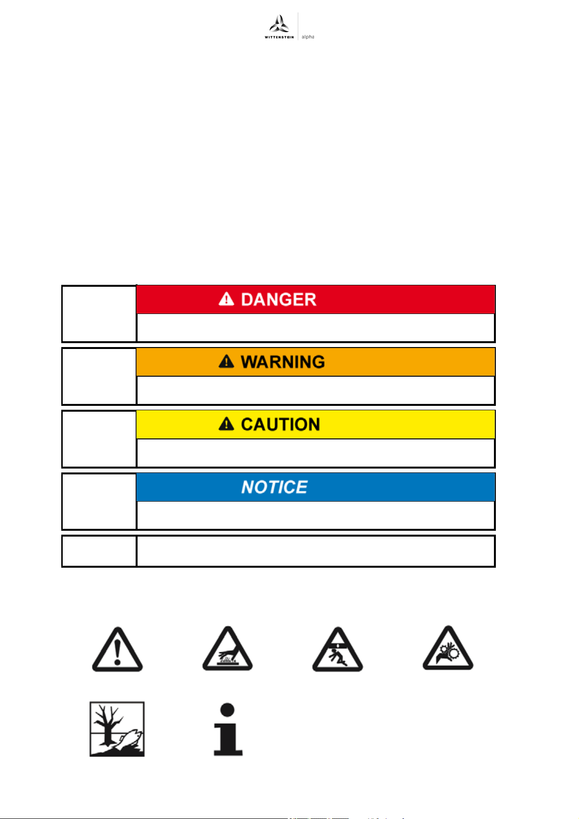
1.1 Signal words
The following signal words are used to bring your attention to dangers, prohibitions, and important
information:
+
1.2 Safety symbols
The following safety symbols are used to bring your attention to dangers, prohibitions, and
important information:
This signal word points to an imminent danger that can cause serious
injuries and even death.
This signal word points to a possible danger that can cause serious
injuries and even death.
This signal word points to a possible danger that can cause slight to
serious injuries.
This signal word points to a possible danger that can cause material
damage.
A note without signal word draws your attention to application tips or
especially important information when handling the gearhead.
General danger Hot surface Suspended loads Danger of being
pulled in
Environment
protection
en-2 2022-D026817 Revision: 07
Information
Page 5
LK+/LPK+/LPBK
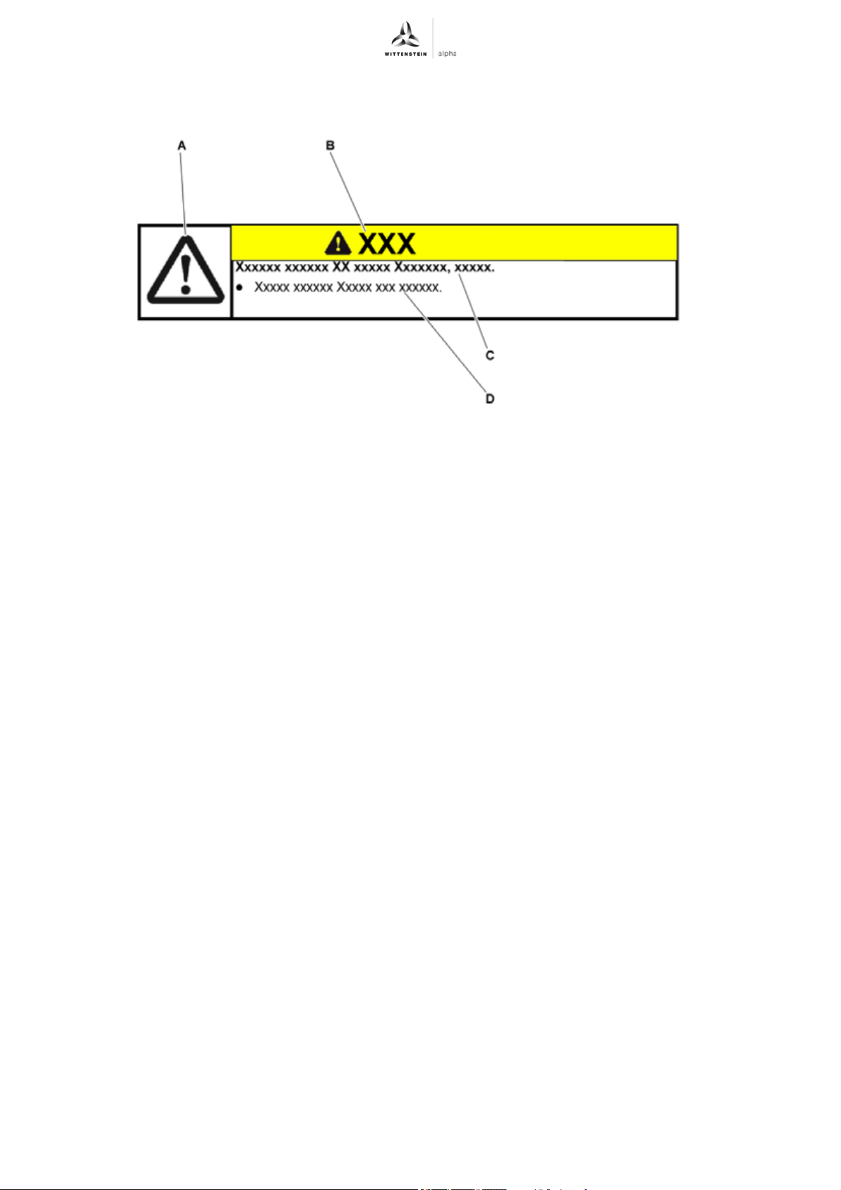
1.3 Design of the safety instructions
The safety instructions of these instructions are designed according to the following pattern:
A = Safety symbol (see Chapter 1.2 "Safety symbols")
B = Signal word (see Chapter 1.1 "Signal words")
C = Type and consequence of the danger
D = Prevention of the danger
+
Safety
1.4 Information symbols
The following information symbols are used:
Indicates an action to be performed
Indicates the results of an action
Provides additional information on handling
2 Safety
These instructions, especially the safety instructions and the rules and regulations valid for the
operating site, must be observed by all persons working with the gearhead.
In addition to the safety instructions in this manual, also observe any (legal and otherwise)
applicable environmental and accident prevention rules and regulations (e.g. personal safety
equipment).
2.1 EC directives
2.1.1 Machinery directive
The gearhead is considered a "machine component" and is therefore not subject to the
EC Machinery Directive 2006/42/EC.
Operation is prohibited within the area of validity of the EC directive until it has been determined
that the machine in which this gearhead is installed corresponds to the regulations within this
directive.
2.1.2 RoHS
The homogeneous materials used in the gearhead fall below the amounts of hazardous materials
limited by directive 2011/65/EU Annex II.
- Lead (0.1%)
- Mercury (0.1%)
- Cadmium (0.01%)
- Hexavalent chromium (0.1%)
- Polybrominated biphenyls (PBB) (0.1%)
- Polybrominated diphenyl ether (PBDE) (0.1%)
Revision: 07 2022-D026817 en-3
Page 6

Safety LK+/LPK+/LPBK
Installation of the gearhead therefore has no effect on the restriction of using certain hazardous
materials in electrical and electronic equipment as required in the directive.
2.2 Dangers
The gearhead has been constructed according to current technological standards and accepted
safety regulations.
To avoid danger to the operator or damage to the machine, the gearhead may be put to use only
for its intended usage (see chapter 2.4 "Intended use") and in a technically flawless and safe state.
Read the general safety instructions before beginning work (see Chapter 2.7 "General safety
instructions").
2.3 Personnel
Only persons who have read and understood these instructions may carry out work on the
gearhead.
2.4 Intended use
The gearhead serves to convert torques and speeds. It is suitable for all industrial applications.
The gearhead may not be operated in areas with explosion hazards. In food processing, the
gearhead may be used only next to or under the foodstuff area.
The gearhead is intended for installation on motors that:
- Correspond to the design B5 (in the event of deviations, consult our Customer Service
department [technical Customer Service department]).
- Have a radial and axial runout tolerance according to DIN EN 50347.
- Have a cylindrical shaft end with tolerance class h6 to k6.
+
2.5 Reasonably foreseeable misuse
Any usage that exceeds the maximum permitted speeds, torques and temperature is considered a
misuse and is therefore prohibited.
Co-riding the gearhead on the drive axle is prohibited. Exceptions require a written approval and
technical statement from WITTENSTEIN alpha GmbH.
2.6 Guarantee and liability
Guarantee and liability claims are excluded for personal injury and material damage in case of
- Ignoring the information on transport and storage
- Improper use (misuse)
- Improper or neglected maintenance and repair
- Improper assembly / disassembly or improper operation (e.g. test run without secure
attachment)
- Operation of the gearhead when safety devices and equipment are defective
- Operation of the gearhead without lubricant
- Operation of a heavily soiled gearhead
- Modifications or reconstructions that have been carried out without the approval of
WITTENSTEIN alpha GmbH
2.7 General safety instructions
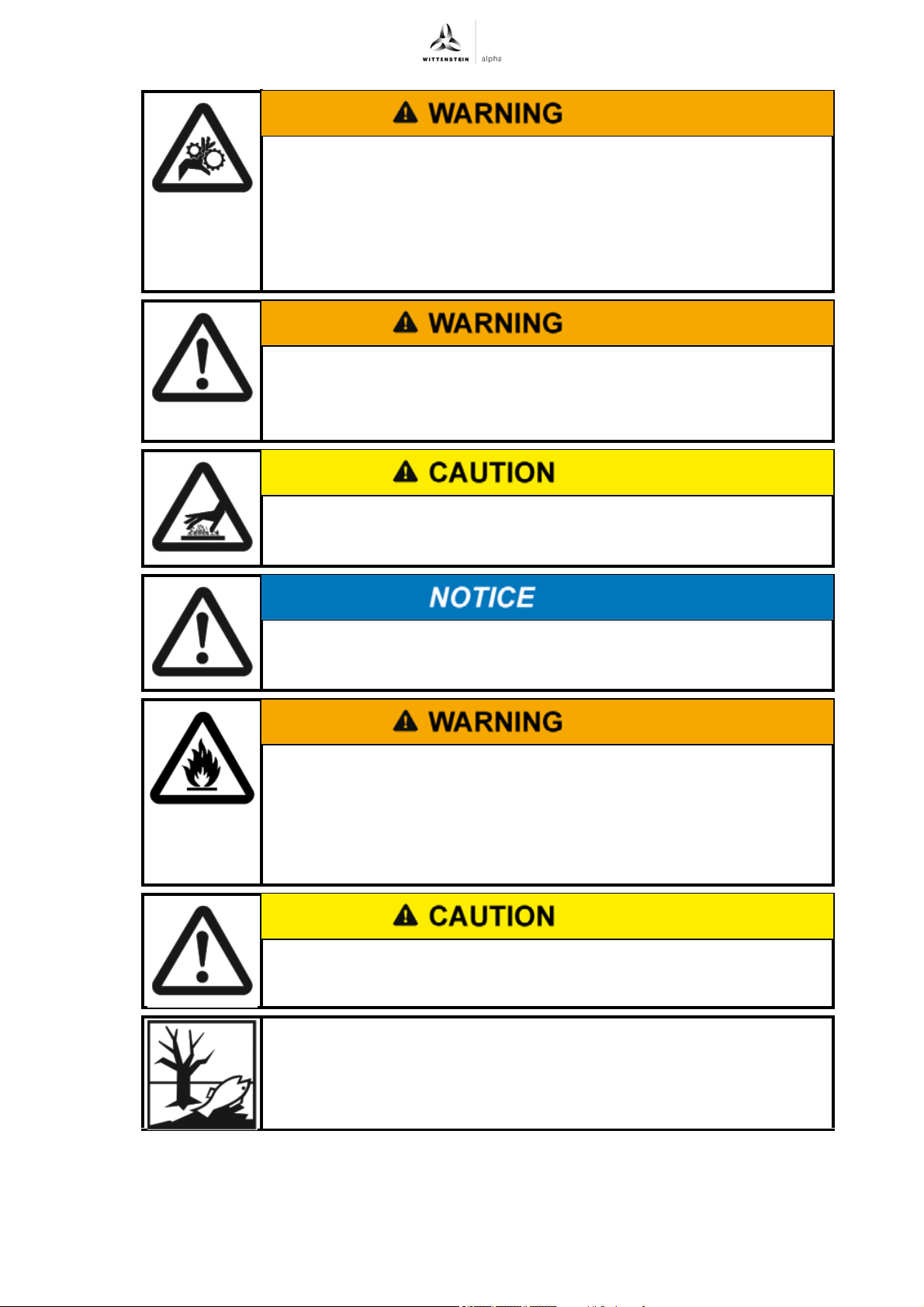
Objects flung out by rotating components can cause serious injuries.
Remove objects and tools from the gearhead before putting it into
operation.
Remove/Secure the shaft key (if available) if the gearhead is operated
without attachments on the output/drive side.
en-4 2022-D026817 Revision: 07
Page 7
LK+/LPK+/LPBK
+
Rotating components on the gearhead can pull in parts of the body
and cause serious injuries and even death.
Keep a sufficient distance to rotating machinery while the gearhead is
running.
Secure the machine against restarting and unintentional movements
during assembly and maintenance work (e.g. uncontrolled lowering of
lifting axes).
A damaged gearhead can cause accidents and injury.
Never use a gearhead that has been overloaded to due misuse or a
machine crash (see chapter 2.5 "Reasonably foreseeable misuse").
Replace the affected gearhead, even if no external damage is visible.
Safety
Hot gearhead housing can cause serious burns.
Touch the gearhead housing only when wearing protective gloves or
after the gearhead has been at standstill for some time.
Loose or overloaded screw connections can damage the gearhead.
Use a calibrated torque wrench to tighten and check all screw
connections for which a tightening torque has been specified.
Lubricants are flammable.
Do not spray with water to extinguish.
Suitable extinguishing agents are powder, foam, water mist, and carbon
dioxide.
Observe the safety instructions of the lubricant manufacturer
(see Chapter 7.4 "Notes on the lubricant used").
Solvents and lubricants can cause skin irritations.
Avoid direct skin contact.
Solvents and lubricants can pollute soil and water.
Use and dispose of cleaning solvents and lubricants properly.
Revision: 07 2022-D026817 en-5
Page 8
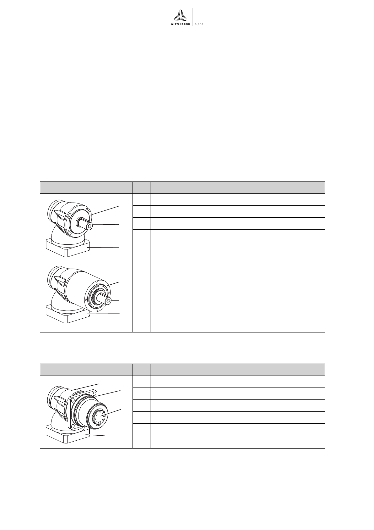
Description of the gearhead LK+/LPK+/LPBK
A
B
C
A
B
C
A
B
C
D
3 Description of the gearhead
The gearhead is a single- or multi-stage angle gear, that is manufactured as standard in the "M"
version (motor installation). The output shaft bearing is designed to withstand high tilting moments
and axial forces.
For applications with special safety requirements (e.g. vertical axes, distorted gear inputs) we
recommend employing exclusively our products alpheno
consulting with WITTENSTEIN alpha GmbH .
The motor centering is realized via the held receptacle for tabs, and not via t h e a dapter plate. Rad i a l
clamping of the motor is avoided.
An adaptation to various motors is realized via an adapter plate and a bushing.
The optional LPBK
+
has an output flange instead of an output shaft. This provides the option of
mounting a toothed belt pulley.
3.1 Overview of the gearhead components
®
, RP+, SP+, TP+, TP+ HIGH TORQUE or
+
+
3.1.1 Overview of the gearhead components LK
/LPK
A Gearhead housing
B Output shaft
C Adapter plate
Tbl-1: Overview of the gearhead components
3.1.2 Overview of the gearhead components LPBK
+
Gearhead components LK+/LPK
+
Gearhead components LPBK
+
+
A Gearhead housing
B Output flange
C Adapter plate
D Mountable flange
Tbl-2: Overview of the gearhead components
en-6 2022-D026817 Revision: 07
Page 9
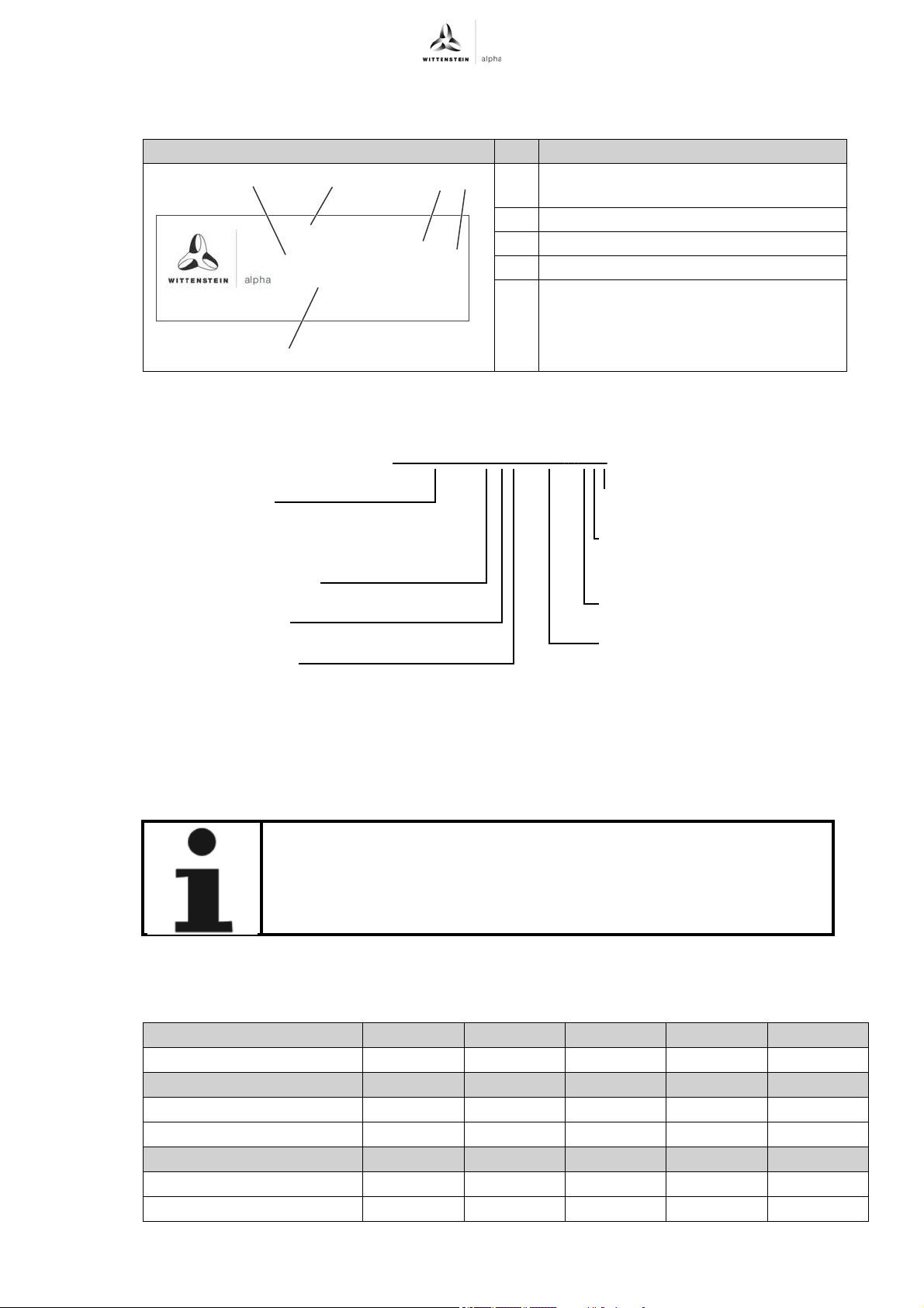
LK+/LPK+/LPBK
WITTENSTEIN alpha GmbH - Walter-Wittenstein-Str.1 - 97999 Igersheim
LPK 090-MO3-100-111
SN: 1234567
DMF: 24/08
Lubrication: For Lifetime
Made in Germany
A
C
D
B
E
i = 100
Gearhead type
LK+/LPK+ 050/070/090/120/155
LPBK+ 070/090/120
Gearhead variations
Gearhead model
Number of stages
Backlash
Clamping hub bore hole
diameter
Output shaft shape
Ratios i
LPK 090 - MO3 - 100 - 111
+
3.2 Identification plate
The identification plate is attached to the gearhead housing.
3.3 Ordering code
Description of the gearhead
Designation
A Ordering code
(see Chapter 3.3 "Ordering code")
BRatio
C Serial number
D Lubricant information
E Production date
Tbl-3: Identification plate (sample values)
3.4 Performance data
For the maximum permitted speeds and torques, refer to
- our catalog,
- our website www.wittenstein-alpha.de,
- the respective customer-specific performance data (X093–D...).
Consult our Customer Service department if the gearhead is older
than a year. You will then receive the valid performance data.
3.5 Weight
The table "Tbl-4" specifies the gearhead weights with a medium-sized adapter plate. If a different
adapter plate is mounted, the actual weight can deviate by up to 10 %.
Gearhead size LK
1–stage [kg] 0.7 1.9 3.2 8.9 19
Gearhead size LPK
Revision: 07 2022-D026817 en-7
Gearhead size LPBK
2–stage [kg] 1.4 3.8 6.9 17 35
3–stage [kg] 1.6 4.2 7.9 19 39
2–stage [kg] —3.46.216—
3–stage [kg] —3.86.917—
+
+
050 070 090 120 155
050 070 090 120 155
+
— 070 090 120 —
Tbl-4: Weight
Page 10
Transport and storage LK+/LPK+/LPBK
3.6 Noise emission
Depending on the gearhead type and product size, the continuous sound pressure level is up to
78 dB(A).
For specifications on your particular product, refer to our catalogue or our Internet page at
http://www.wittenstein-alpha.de or contact our Customer Service department.
Observe the total noise pressure level of the machine.
4 Transport and storage
4.1 Scope of delivery
Check the completeness of the delivery against the delivery note.
Immediately notify the carrier, the insurance company, or WITTENSTEIN alpha GmbH in
writing of any missing parts or damage.
4.2 Packaging
The gearhead is delivered packed in foil and cardboard boxes.
Dispose of the packaging materials at recycling sites intended for that. Observe the locally
valid regulations for disposals.
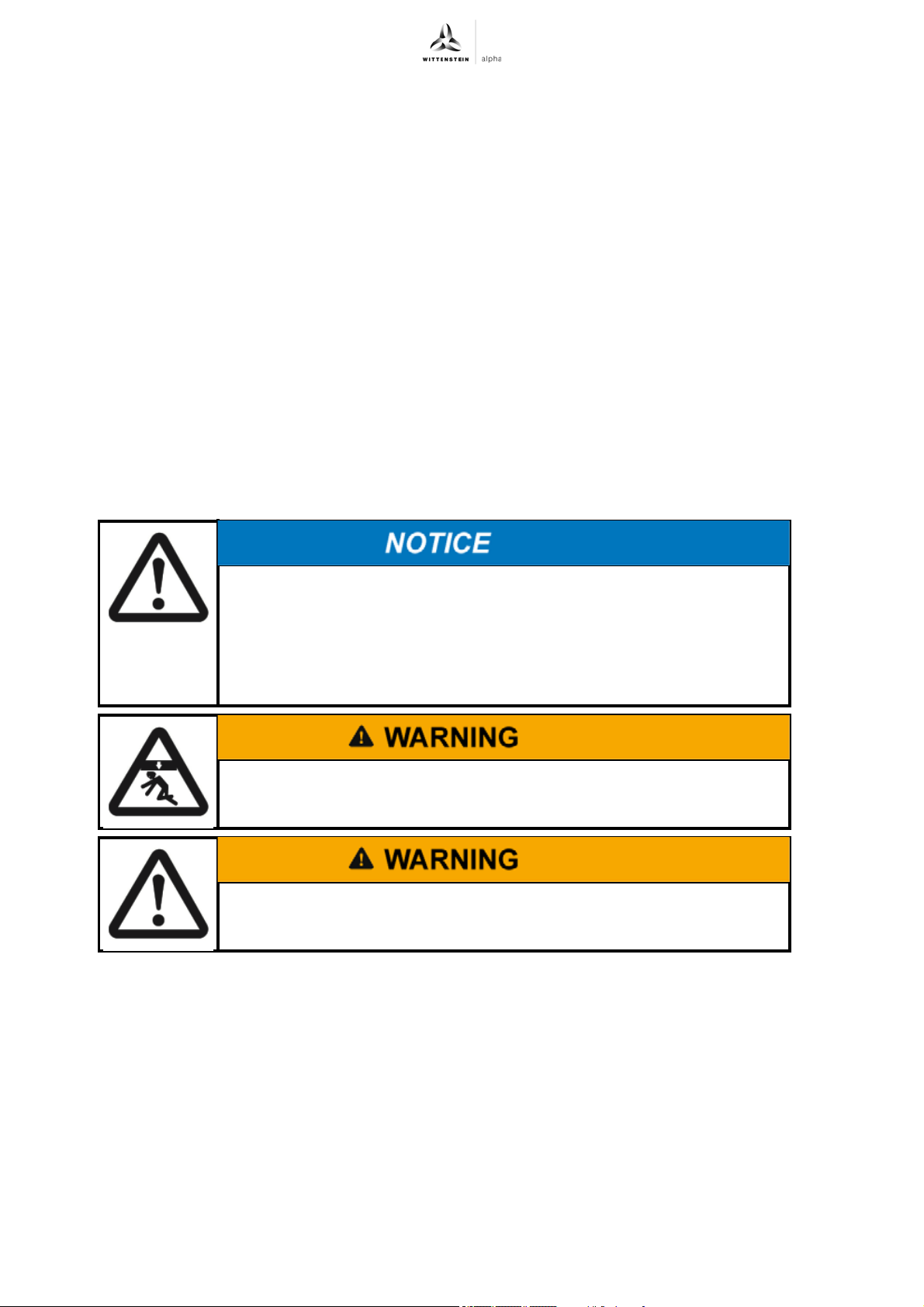
+
4.3 Transport
Hard knocks, because of falling or hard dropping, can damage the
gearhead.
Use only hoisting equipment and transportation devices with sufficient
capacity.
The permitted lifting weight of a hoist may not be exceeded.
Lower the gearhead slowly.
Suspended loads may fall and cause serious injuries and even death.
Do not stand under suspended loads.
The plastic lid on the gearhead may come off.
Never transport the gearhead by the plastic lid.
No special transport mode is prescribed to transport the gearhead.
For specifications on the weights see Chapter 3.5 "Weight".
4.4 Storage
Store the gearhead in horizontal position and dry surroundings at a temperature of 0 °C to +40 °C
in the original packaging. Store the gearhead for a maximum of 2 years. Consult our Customer
Service department if the conditions are different.
For storage logistics, we recommend the "first in –first out" method.
en-8 2022-D026817 Revision: 07
Page 11
LK+/LPK+/LPBK
5 Assembly
Read the general safety instructions before beginning work (see Chapter 2.7 "General safety
instructions").
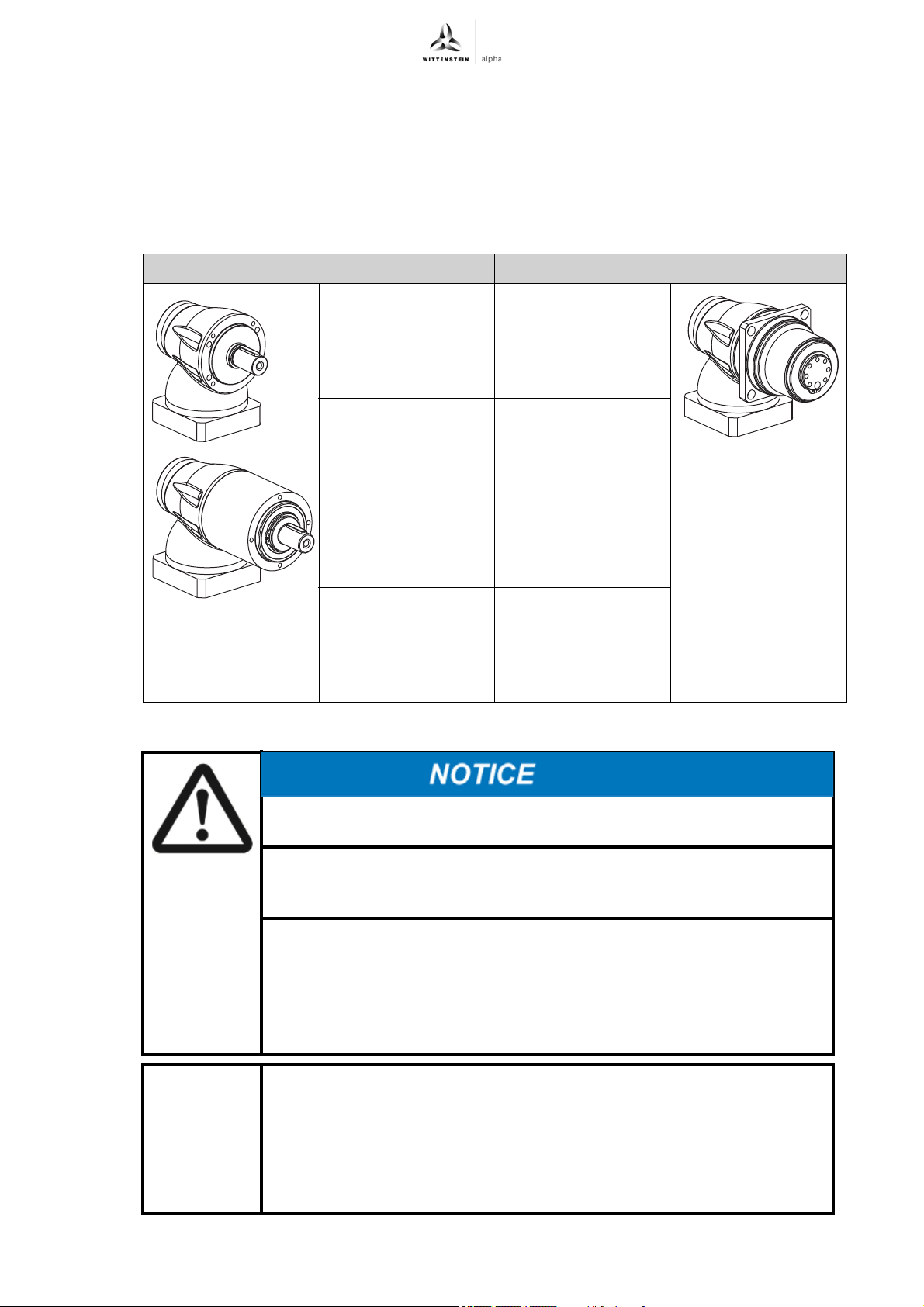
5.1 Preparations
The different assembly sequences for LK
Our Customer Service department is available to answer any questions.
+
LK+/LPK
Assembly
+
/LPK+, and LPBK+ are listed in the table "Tbl-5".
+
LPBK
— 1
5.2 "Mounting the
gearhead to a
machine (LPBK
+
only)"
+
1
5.3 "Mounting the
motor on the
gearhead"
2
5.4 "Components
mounted on the
output side"
3
5.3 "Mounting the
5.4 "Components
mounted on the
2
motor on the
gearhead"
3
output side"
—
5.5 "Mounting the
gearhead to a
+
machine (LK
/LPK+
only)"
Tbl-5: Assembly sequence
Pressurized air can damage the gearbox seals.
Do not use pressurized air to clean the gearbox.
Directly sprayed cleaning agents can alter the frictional values of the
clamping hub.
Only spray cleaning agents onto a cloth for wiping off the clamping hub.
Operation without an adapter plate might lead to damage.
Only install your own adapter plate or replace an adapter plate according
to the specifications of WITTENSTEIN alpha GmbH. Our Customer
Service department will provide you with disassembly instructions for this
purpose.
Operation without an adapter plate is prohibited.
In rare cases, a grease lubricated gearbox may show a small leak at
the input (sweating).
To prevent seeping, we recommend to seal the surfaces between
- adapter plate and drive housing (gearbox), as well as between
- adapter plate and motor,
using a surface sealing adhesive (e.g. Loctite
Check that the motor meets the specifications in Chapter 2.4 "Intended use".
Revision: 07 2022-D026817 en-9
®
573 or 574).
Page 12
Assembly LK+/LPK+/LPBK
Clean / Degrease the following components with a clean and lint-free cloth and grease-
dissolving, non-aggressive detergent:
- All fitting surfaces to neighboring components
- Centering
- The motor shaft
- The inside diameter of the clamping hub
- The bushing inside and out
Dry all fitting surfaces to neighboring components in order to achieve the proper friction values
of the screw connections.
Check the fitting surfaces additionally for damage and impurities.
Select screws for fastening the motor to the adapter plate according to the motor
manufacturer's specifications. Observe the minimum screw depth as determined by the
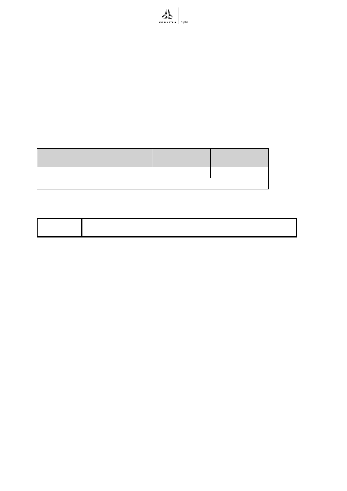
property class (see Table "Tbl-6").
+
Property class of the screws for
fastening the motor
Minimum screw depth 1.5 x d 1.8 x d
d = Screw diameter
Tbl-6: Minimum screw depth of the screws for fastening the motor to the adapter plate
5.2 Mounting the gearhead to a machine (LPBK
Observe the safety and processing instructions of the cleaning agents
and threadlocker to be used.
8.8 10.9
+
only)
en-10 2022-D026817 Revision: 07
Page 13
LK+/LPK+/LPBK
D
B
O
M
N
+
Assembly
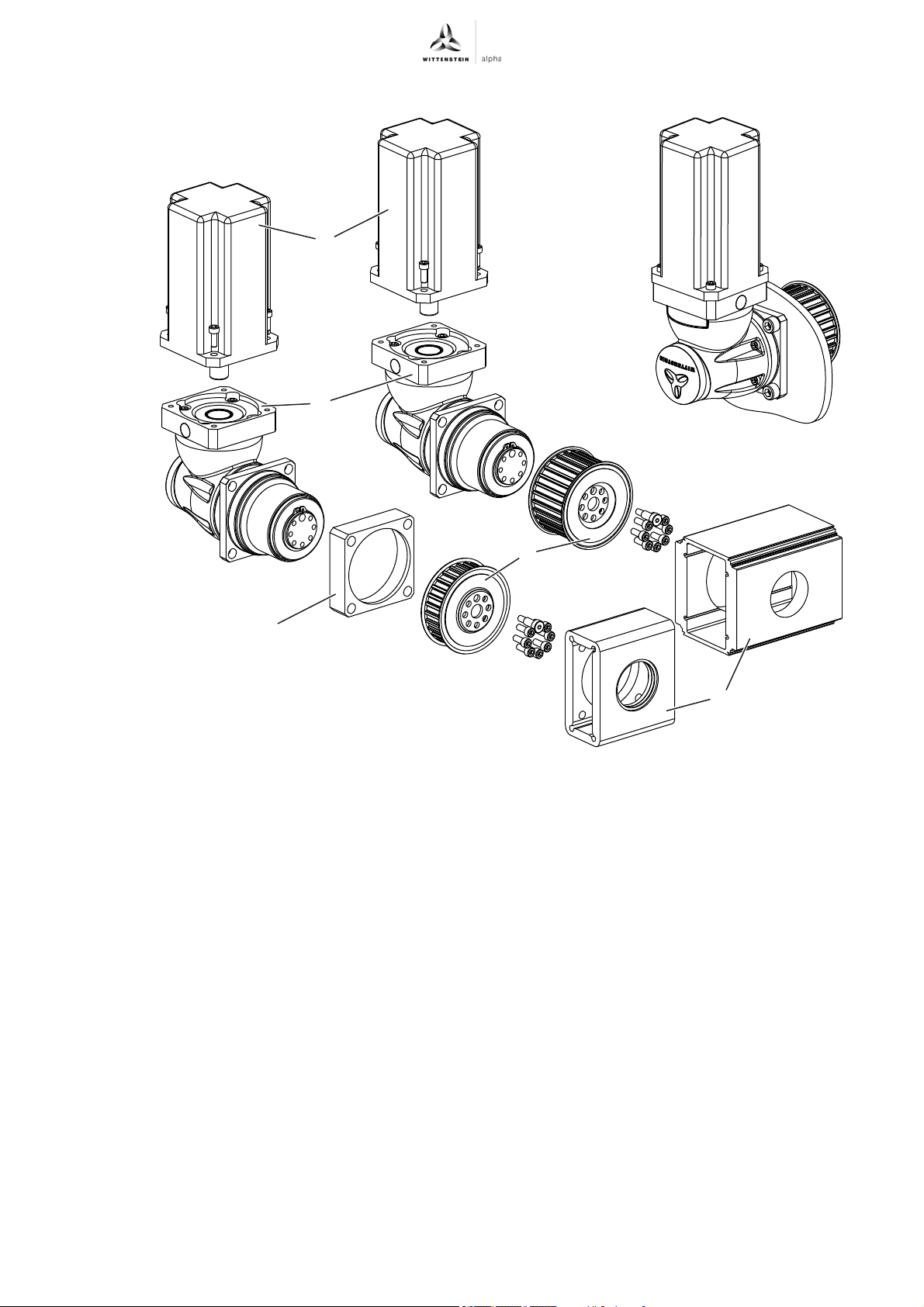
If necessary, a spacer (M) should be placed between gearhead and machine to fine-tune the
gearhead position. Such a spacer is not part of the drive's scope of delivery and needs to be
provided by the customer.
Thoroughly clean the output flange, centering, fitting surface, spacer and toothed belt pulley.
The anti-corrosion agent on the toothed belt pulley must be removed.
®
To remove the anti-corrosion agent, use acetone or Loctite
Also clean the browned toothed belt pulley with a brush and remove any salt residue between
7063, and a clean, lint-free cloth.
the flanged wheel and toothed belt wheel.
The fastening screws need to be provided by the customer.
For appropriate screw sizes and tightening torques, see Chapter 9.2 "Specifications for
mounting on a machine", Table "Tbl-17".
When using hollow sections (N): Position the toothed belt pulley (O) in the hollow section before
attaching the gearhead.
®
243) to the fastening screws.
Apply threadlocker (e.g., Loctite
Fasten the gearhead to the machine with the fastening screws through the through-holes.
Mount the gearhead in such a way that the identification plate remains legible, if possible.
Do not use washers (e.g. plain washers, tooth lock washers).
Revision: 07 2022-D026817 en-11
Page 14
Assembly LK+/LPK+/LPBK
S
C
J
C
H
D
B
F
C
H
J
K
L
5.3 Mounting the motor on the gearhead
Observe the specifications and safety instructions of the motor
manufacturer.
Observe the safety and processing instructions for the threadlocker to be
used.
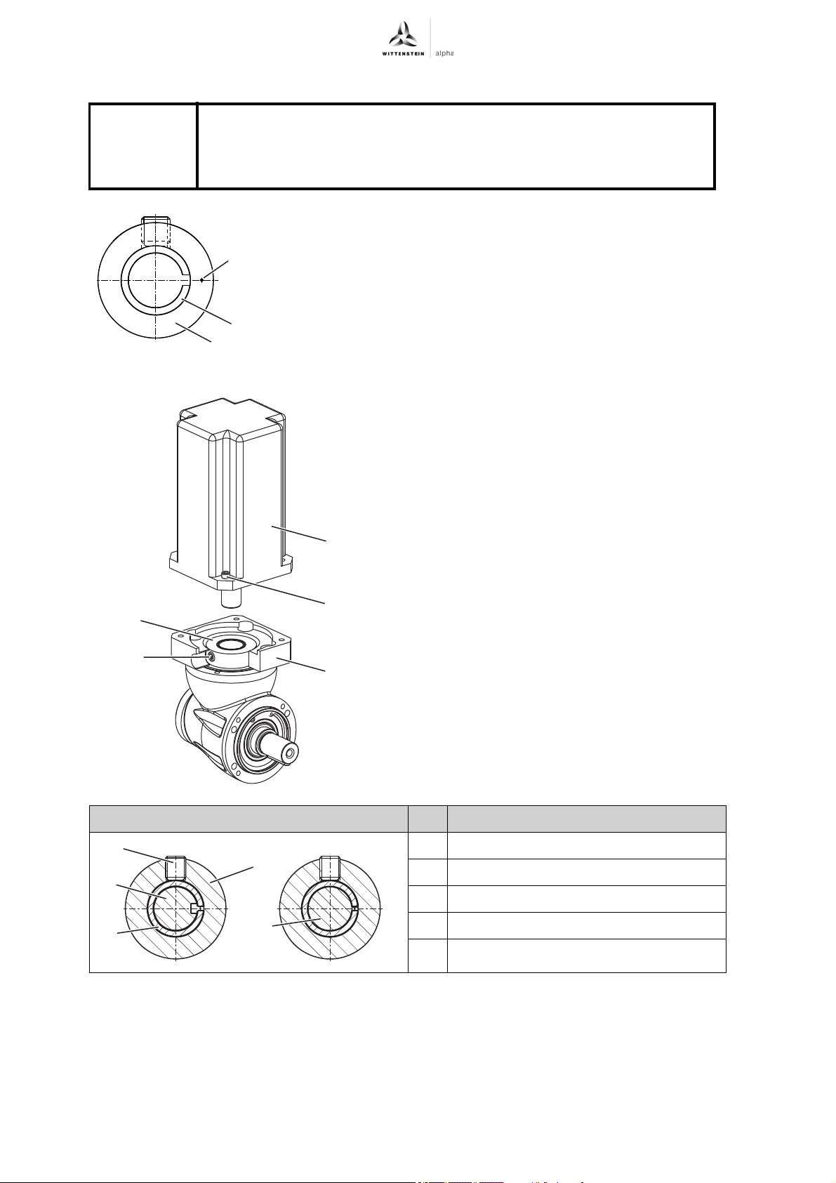
Insert the bushing (J) into the clamping hub (C). Align the bushing
in such a way that the slot is pointing toward the centering bore (S).
Ensure that the motor is mounted if possible in
a vertical direction.
If the motor shaft has a shaft key, remove the
shaft key.
If recommended by the motor manufacturer,
apply a half key.
Turn the clamping hub (C) so that the threaded
pin (H) can be reached through the mounting
bore.
Push the motor shaft into the clamping hub of
the gearhead (E).
The motor shaft should slip in easily. If this is
not the case, the threaded pin needs to be
loosened more.
The slot of the bushing has to line up with the
groove (if present) of the motor shaft and be
rotated by 90° against the threaded pin; see
table "Tbl-7".
No gap is permitted between motor (D) and
the adapter plate (B).
+
Designation
C Clamping hub
H Threaded pin
J Bushing
K Keyed shaft
L Smooth shaft
Tbl-7: Arrangement of motor shaft, clamping hub, and bushing
Smear threadlocker (e.g. Loctite
Fasten the motor (D) onto the adapter plate (B) with the four screws (F). Evenly tighten the
screws crosswise with increasing torque.
®
243) onto the four screws (F).
en-12 2022-D026817 Revision: 07
Page 15
LK+/LPK+/LPBK
Tighten the threaded pin (H) of the clamping hub (C).
+
For screw sizes and prescribed tightening torques, see Chapter 9.1 "Specifications for
mounting onto a motor", Table "Tbl-14".
Press the enclosed stopper plugs up to their stop into the mounting bores of the
adapter plate (B).
5.4 Components mounted on the output side
Clamping forces during assembly can damage the gearhead.
Mount the mounting parts onto the output shaft without using force.
Never attempt to assemble by force or hammering!
Only use suitable tools and devices for assembly.
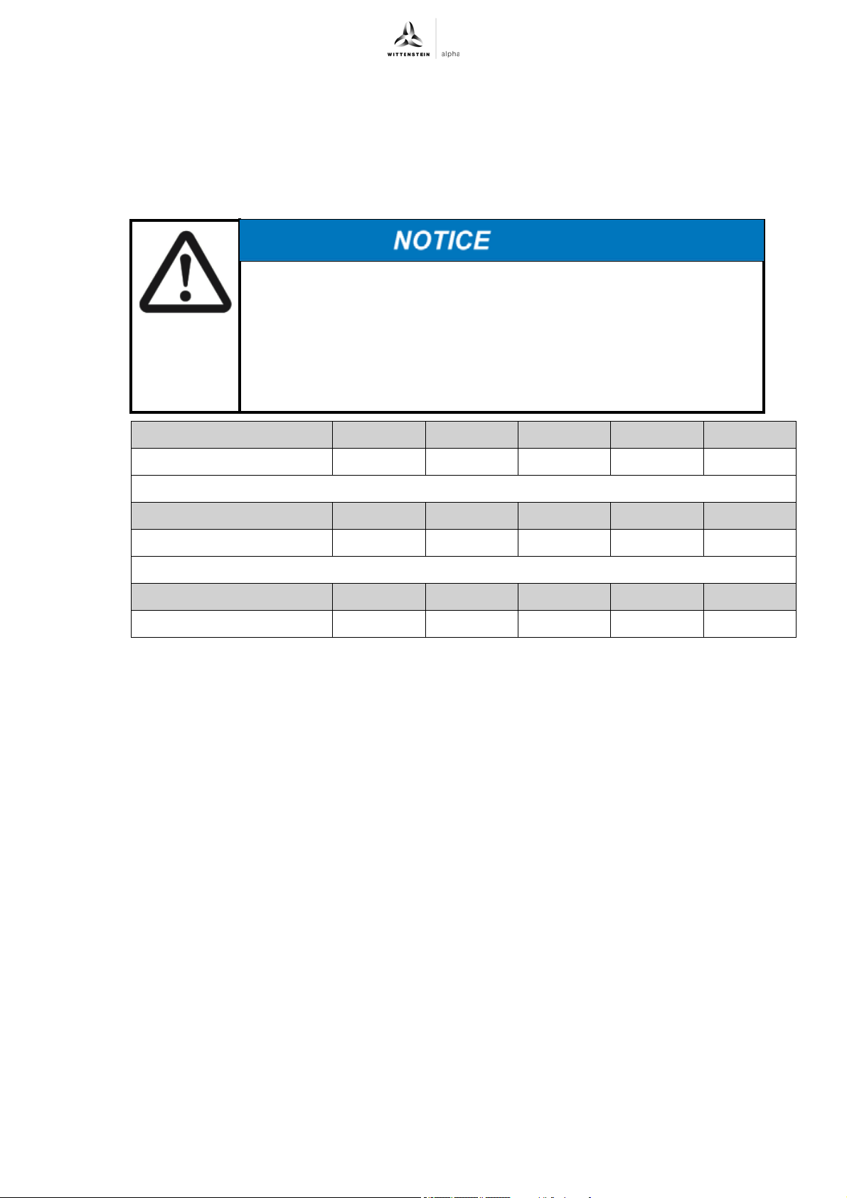
Make sure not to exceed the maximum permissible static axial forces on
the output bearing (see Table "Tbl-8") when pulling or shrink-fitting a
mounting part onto the output shaft.
Assembly
Gearhead size LK
F
2AMAX
[N]
Gearhead size LPK
F
2AMAX
[N]
Gearhead size LPBK
F
Tbl-8: Maximum permissible static axial forces at static load rating (s0) = 1.8 and radial force (FR) = 0
2AMAX
[N]
+
050 070 090 120 155
100 200 450 750 1000
+
050 070 090 120 155
700 1550 1900 4000 6000
+
— 070 090 120 —
— 1550 1900 4000 —
Revision: 07 2022-D026817 en-13
Page 16
Assembly LK+/LPK+/LPBK
P
R
O
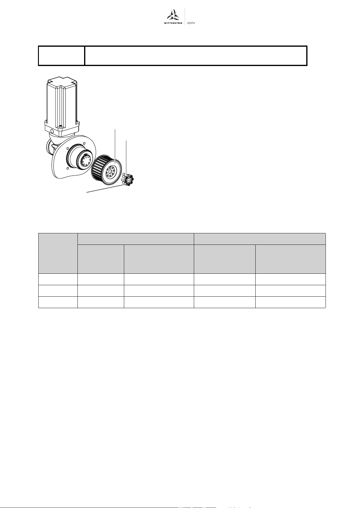
5.4.1 Mountings on the output flange (LPBK+ only)
Observe the safety and processing instructions of the cleaning agents
and threadlocker to be used.
Only the LPBK+ version features an output flange on
which a toothed belt pulley (O) can be mounted with bolts.
Thoroughly clean the output flange, centering, fitting
surface, spacer and toothed belt pulley. The anticorrosion agent on the toothed belt pulley must be
removed.
To remove the anti-corrosion agent, use acetone or
Loctite
Also clean the browned toothed belt pulley with a brush
and remove any salt residue between the flanged
wheel and toothed belt wheel.
Place the toothed belt pulley onto the output flange.
Apply threadlocker (e.g., Loctite
and tighten the screws by hand initially.
Tighten the fastening screws (P) and the close-
tolerance bolt (R) (1 piece) in diagonal order, making at
least two passes to the prescribed tightening torque
(see table "Tbl-9").
®
7063, and a clean, lint-free cloth.
®
243) to the screws,
+
Gearhead
size
+
LPBK
[mm] x [mm]
Close-tolerance bolt Fastening screw
Thread x
Depth
Tightening torque
[Nm]
Property class 10.9
Quantity x Thread
x Depth
[ ] x [mm] x [mm]
Tightening torque
[Nm]
Property class 12.9
070 M5 x 12 7.69 5 x M5 x 12 9
090 M6 x 16 13.2 7 x M6 x 16 15.4
120 M6 x 16 13.2 7 x M8 x 20 37.3
Tbl-9: Fastening the toothed belt pulley
The tension of the tooth belt is brought about by its construction. The toothed belt's prestressing
force influences the ball bearing life of the gearhead.
Use our cymex
®
specification software to determine the theoretical bearing life for each
application scenario.
Set the toothed belt so that there are no lateral starting loads pressing on the toothed belt
pulley.
en-14 2022-D026817 Revision: 07
Page 17
LK+/LPK+/LPBK
+
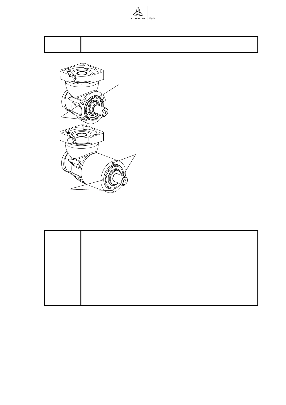
5.5 Mounting the gearhead to a machine (LK+/LPK+ only)
Observe the safety and processing instructions for the threadlocker to be
used.
Startup and operation
M
M
M
M
Apply threadlocker (e.g., Loctite
®
243) to the
fastening screws.
Fasten the gearhead to the machine with the
fastening screws only through the threaded
bores (M).
Mount the gearhead in such a way that the
identification plate remains legible.
Do not use washers (e.g. plain washers,
tooth lock washers).
For appropriate screw sizes and tightening
torques, see Chapter 9.2 "Specifications for
mounting on a machine", Tables "Tbl-15"
and "Tbl-16".
6 Startup and operation
Read the general safety instructions before beginning work (see Chapter 2.7 "General safety
instructions").
Improper use can cause damage to the gearhead.
Make sure that
- the ambient temperature does not drop below –15 °C or
exceed +40 °C and
- the operating temperature does not exceed +90 °C.
Avoid icing, which can damage the seals.
For other conditions of use, consult our Customer Service department.
Only use the gearhead only up to its maximum limit values, see
Chapter 3.4 "Performance data".
Only use the gearhead only in a clean, dust-free and dry environment.
Revision: 07 2022-D026817 en-15
Page 18
Maintenance and disposal LK+/LPK+/LPBK
7 Maintenance and disposal
Read the general safety instructions before beginning work (see Chapter 2.7 "General safety
instructions").
7.1 Maintenance work
7.1.1 Visual inspection
Check the entire gearhead for exterior damage.
The sealings are subject to wear. Therefore also check the gearhead for leakage during each
visual inspection.
Check the mounting position, so that no foreign medium (e.g. oil) has collected on the output
shaft.
7.1.2 Checking the tightening torques
Check the tightening torque of the threaded pin on the motor mounting.
The prescribed tightening torques can be found in Chapter 9.1 "Specifications for mounting
onto a motor", Table "Tbl-14".
Check the tightening torque of the fastening screws on the gearhead housing. If, while
checking the tightening torque, you discover that a fastening screw can be further tightened,
follow the instructions in "Remounting the screw".
The prescribed tightening torques can be found in Chapter 9.2 "Specifications for mounting on
a machine", Tables "Tbl-15", "Tbl-16" and "Tbl-17".
For LPBK
The prescribed tightening torques can be found in Chapter 5.4 "Components mounted on the
output side", Table "Tbl-9".
+
gearheads, also check the fastening screws on the toothed belt pulley.
+
Remounting the screw
Make sure that it is possible to remount the screw on the gearhead
without damaging the entire machine.
Loosen the screw.
Remove the glue residue from the threaded bore and the screw.
De-grease the screw.
Coat the screw with a threadlocker (e.g. Loctite
Screw in the screw and tighten it with the prescribed tightening torque.
7.2 Startup after maintenance work
Clean the outside of the gearhead.
Attach all safety devices.
Do a trial run before releasing the gearhead again for operation.
7.3 Maintenance schedule
Maintenance work At startup For the first time
Visual inspection XXX
®
243).
after 500 operating
hours or 3 months
Every
3 months
Yearly
Checking the
XX X
tightening torques
Tbl-10: Maintenance schedule
en-16 2022-D026817 Revision: 07
Page 19
LK+/LPK+/LPBK
7.4 Notes on the lubricant used
The manufacturer listed below will provide any further information on the lubricants:
Castrol Industrie GmbH, Mönchengladbach
7.5 Disposal
Consult our Customer Service department for supplementary information on exchanging the
adapter plate, on disassembly, and on disposal of the gearhead.
Dispose of the gearhead at the recycling sites intended for this purpose.
Observe the locally valid regulations for disposals.
+
All gearheads are lubricated for their service life by the manufacturer with a
mineral oil-based lithium soap grease or with a food-safe synthetic grease
(carbon hydride oil, aluminum complex soap) (see identification plate). All
bearings are permanently lubricated by the company.
Standard lubricants Lubricants for the food industry
Tel.: + 49 2161 909-30
www.castrol.com
Malfunctions
(USDA-H1 registered)
Klüber Lubrication München KG, München
Tel.: + 49 89 7876–0
www.klueber.com
Tbl-11: Lubricant manufacturers
8 Malfunctions
Fault Possible cause Solution
Increased
operating
temperature
Increased
noises
during
operation
Loss of
lubricant
The gearhead is not suited for the task. Check the technical specifications.
Changed operational behavior can be an indication of existing damage
to the gearhead or cause damage to the gearhead.
Do not put the gearhead back into operation until the cause of the
malfunction has been rectified.
Rectifying of malfunctions may only be done by specially trained
technicians.
Motor is heating the gearhead. Check the wiring of the motor.
Ensure adequate cooling.
Change the motor.
Ambient temperature too high. Ensure adequate cooling.
Distortion in motor mounting Please consult our Customer Service
Damaged bearings
Damaged gear teeth
Lubricant quantity too high Wipe off discharged lubricant and
continue to watch the gearhead. Lubricant
discharge must stop after a short time.
Seals not tight Please consult our Customer Service
Tbl-12: Malfunctions
Department.
Department.
Revision: 07 2022-D026817 en-17
Page 20
Appendix LK+/LPK+/LPBK
C
H
J
K
L
9 Appendix
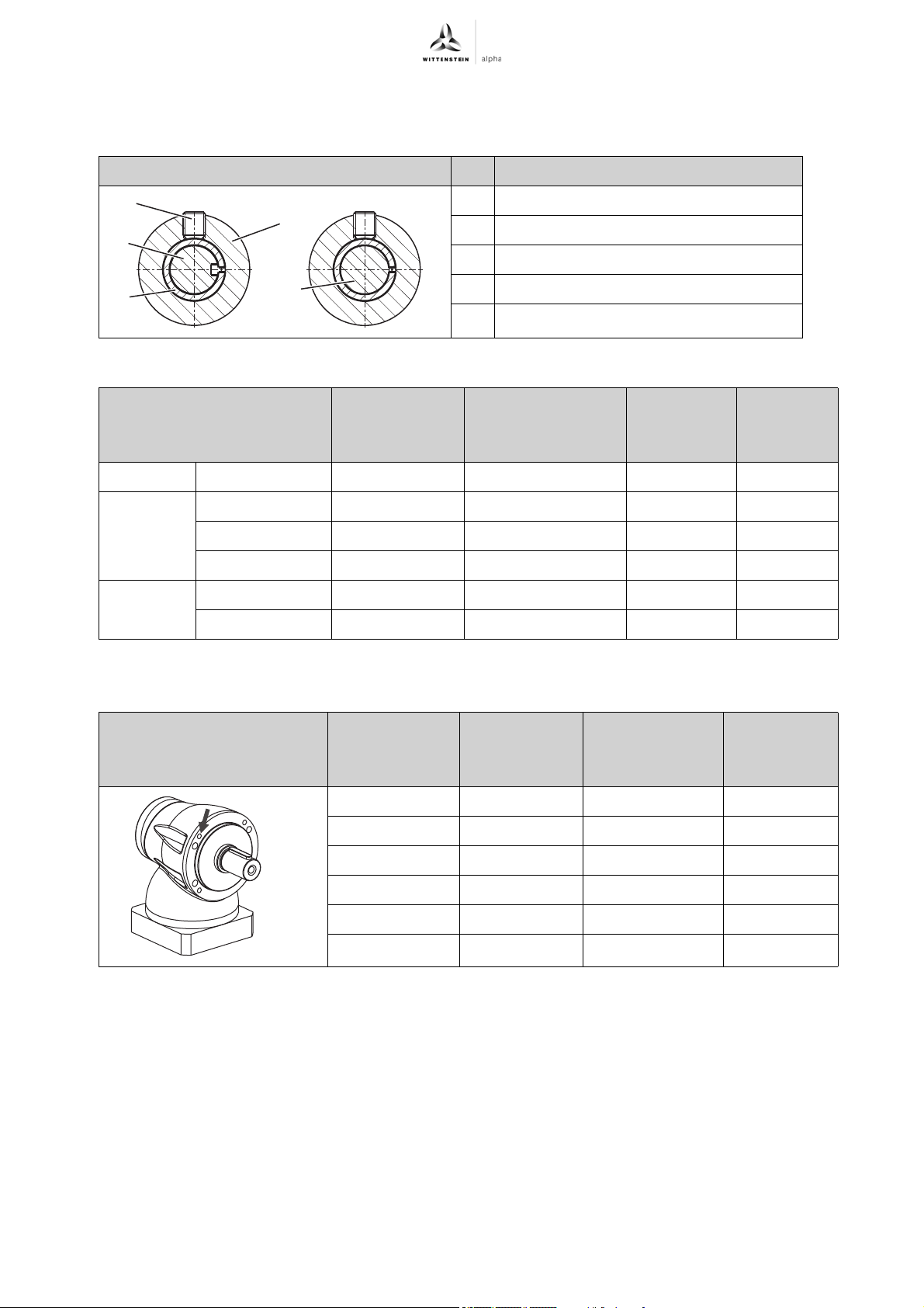
9.1 Specifications for mounting onto a motor
Designation
C Clamping hub
H Threaded pin
J Bushing
K Keyed motor shaft
L Smooth motor shaft
Tbl-13: Arrangement of motor shaft, clamping hub, and bushing
+
Gearhead size Clamping hub
internal Ø
[mm]
+
/LPK
/LPK+/
+
+
050 11 3 5.6 45
070 16 4 14 80
090 24 5 23 100
LK
LK
LPBK
+
120 32 6 45 150
+
LK
/LPK+155, 1-/2-stage 42 8 78 180
155, 3-stage 32 6 45 150
Tbl-14: Specifications for mounting onto a motor
9.2 Specifications for mounting on a machine
Gearhead size
+
LK
050 44 M4 / 8.8 2.64
070 62 M5 / 8.8 5.24
Width across flats,
threaded pin (H)
[mm]
Hole circle Ø
[mm]
Screw size /
property class
Tightening
torque
[Nm]
Max. axial
force
[N]
Tightening
torque
[Nm]
090 80 M6 / 8.8 8.99
120 108 M8 / 8.8 21.7
155 140 M10 / 8.8 42.7
Tbl-15: Threaded bores in gearhead housing LK
+
en-18 2022-D026817 Revision: 07
Page 21
LK+/LPK+/LPBK
+
Appendix
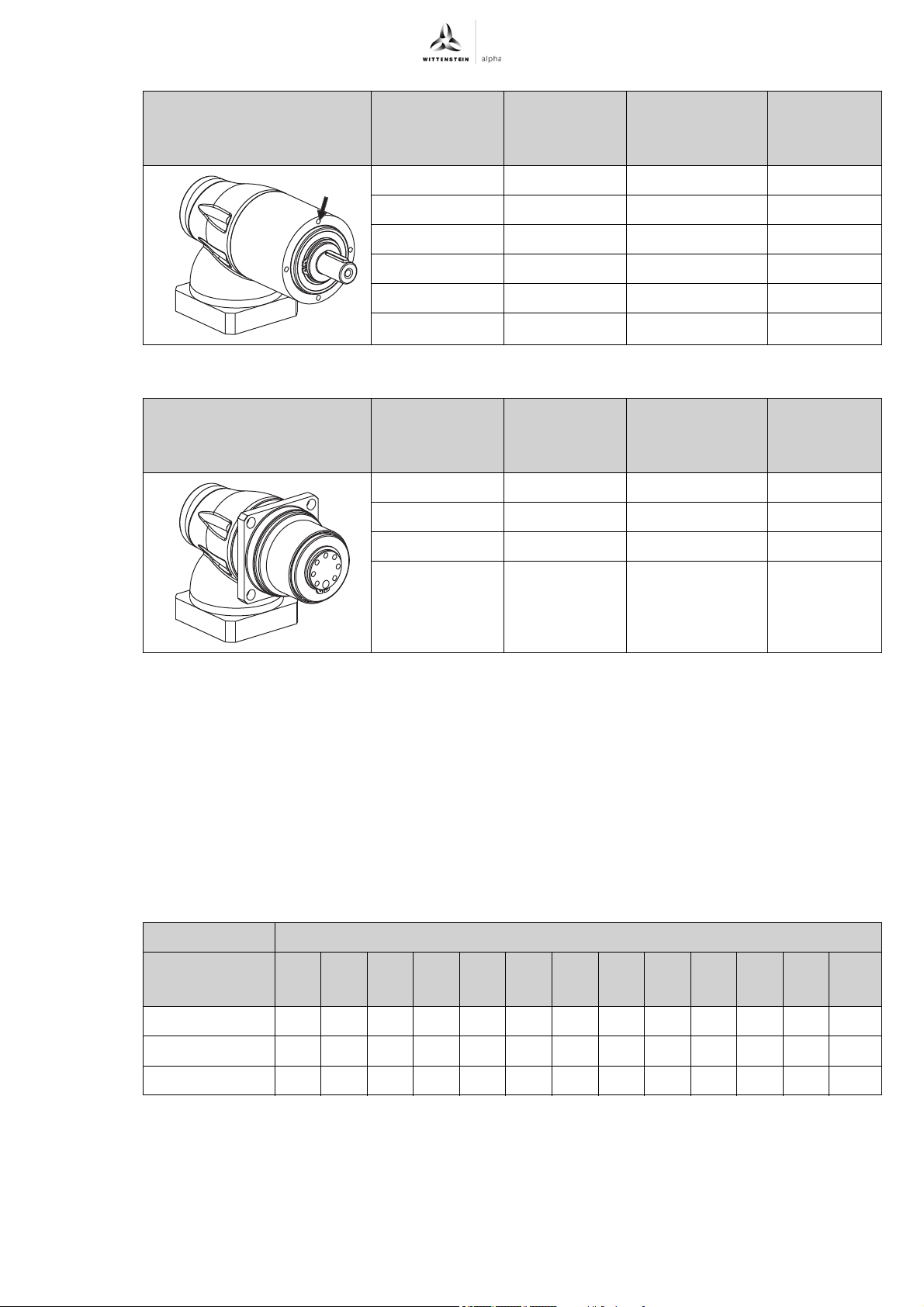
Gearhead size
+
LPK
Hole circle Ø
[mm]
Screw size /
property class
050 44 M4 / 12.9 4.55
070 62 M5 / 12.9 9
090 80 M6 / 12.9 15.4
120 108 M8 / 12.9 37.3
155 140 M10 / 12.9 73.4
Tbl-16: Threaded bores in gearhead housing LPK
Gearhead size
+
LPBK
Hole circle Ø
[mm]
For screw size /
property class
070 82 M8 / 12.9 37.3
090 106 M10 / 12.9 73.4
120 144 M12 / 12.9 126
Tightening
torque
[Nm]
+
Tightening
torque
[Nm]
Tbl-17: Through-holes in gearhead housing LPBK
+
9.3 Tightening torques for common thread sizes in general mechanical engineering
The specified tightening torques for headless screws and nuts are calculated values and are based
on the following conditions:
- Calculation in accordance with VDI 2230 (February 2003 version)
- Friction value for thread and contact surfaces µ=0.10
- Exploitation of the yield stress 90%
- Torque tools type II classes A and D in accordance with ISO 6789
The settings are values rounded to usual commercial scale gradations or setting possibilities.
Set these values precisely on the scale.
Tightening torque [Nm] with thread
Property class
M3 M4 M5 M6 M8 M10 M12 M14 M16 M18 M20 M22 M24
Screw / nut
8.8 / 8 1.15 2.64 5.2 9.0 21.5 42.5 73.5 118 180 258 362 495 625
10.9 / 10 1.68 3.88 7.6 13.2 32.0 62.5 108 173 264 368 520 700 890
12.9 / 12 1.97 4.55 9.0 15.4 37.5 73.5 126 202 310 430 605 820 1040
Tbl-18: Tightening torques for headless screws and nuts
Revision: 07 2022-D026817 en-19
Page 22

AC: XXXXXXXX 2022-D062611Revision: 02
WITTENSTEIN alpha GmbH ꞏ Walter-Wittenstein-Straße 1 ꞏ 97999 Igersheim ꞏ Germany
Tel. +49 7931 493-0 ꞏ [email protected]
WITTENSTEIN ‒ one with the future
www.wittenstein-alpha.de
 Loading...