

Page 1
H0402EN00
10.2011
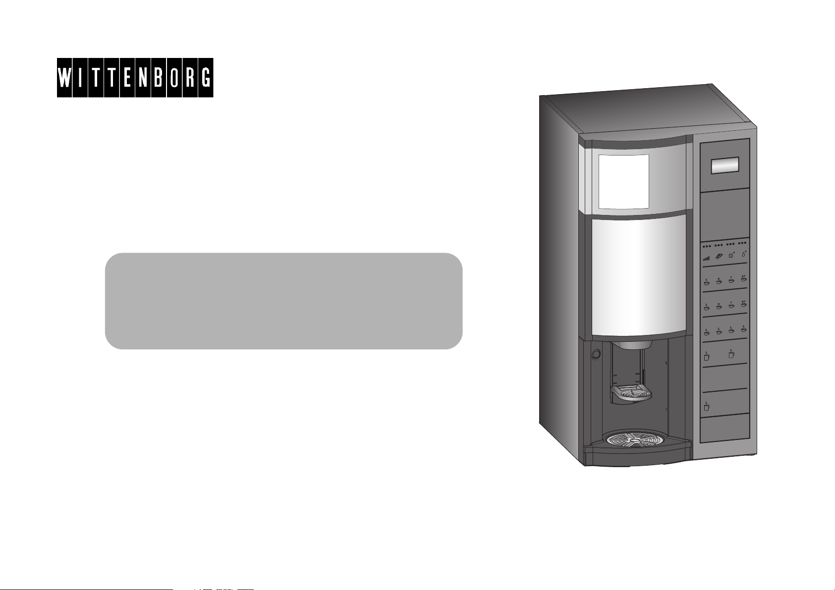
OPERATOR MANUAL
FB 7100 PLUS
Page 2
The symbol indicates that the machine may not be disposed of as ordinary waste; it must be disposed of in accordance with the
provisions of the European directive 2002/96/CE (Waste Electrical and Electronics Equipments - WEEE) and of any resulting national
laws, for preventing any possible adverse effects on the environment and on human health.
For correct disposal of the machine, contact the dealer from whom you have purchased the machine or our after sales service.
---------------------------------------------------------------------------------------------------------------------------------------------------------------------------------
---
All packing materials shall be disposed of in a manner which is safe for the environment.
Copyright © All rights reserved. This manual may not be translated or copied or reproduced in any form or by any means in whole or in part without the prior written consent
of N&W GLOBAL VENDING SpA.
N&W GLOBAL VENDING SpA issues no explanations or guarantees with regard to the contents of this publication and expressly disclaims all responsibility for any implied
guarantees. N&W GLOBAL VENDING SpA reserves the right to revise and change the contents of this manual without notice.
Original document.
Published by N&W GLOBAL VENDING SpA
Via Roma 24, 24030 Valbrembo (BG) - Italy.
Part No: H0402EN00
Published in 2011, week 41
Page 3

TABLE OF CONTENTS
Table of contents
Introduction................................................................................. 1
Safety........................................................................................... 2
Technical Data ............................................................................ 4
Product presentation
Vending machine components ..................................................... 6
- Machine front.............................................................................. 6
- Operating panel.......................................................................... 6
- Machine cabinet ......................................................................... 7
Operation
Pot panel (Multibrew).................................................................... 8
Discount lock ................................................................................ 9
Navigation buttons........................................................................ 10
- Settings buttons.......................................................................... 12
Overview of Operator and Technicians functions......................... 13
Short cuts ..................................................................................... 21
Additional Features....................................................................... 24
- Multi-vend................................................................................... 24
- Single-vend ................................................................................ 24
Cleaning and maintenance
General instructions...................................................................... 25
Maintenance routines ................................................................... 26
- Schedule for regular maintenance routines................................ 26
- Schedule for deep and occasional maintenance routines.......... 27
Regular cleaning
Opening and disconnecting machine ........................................... 29
Preparing for filling of canisters .................................................... 29
Filling the instant ingredient canisters .......................................... 29
Filling the freshbrew ingredient canister....................................... 30
Removing the solid waste container............................................. 31
Cleaning the cup carrier ............................................................... 32
Unlocking the drip tray.................................................................. 33
Cleaning the drip tray................................................................... 33
Cleaning inside and outside......................................................... 34
Mounting of cleaned parts ........................................................... 34
Rinsing machine .......................................................................... 35
Last check.................................................................................... 36
Deep cleaning
Hygiene kit ................................................................................... 37
Opening and disconnecting machine........................................... 37
Filling the instant ingredient canisters.......................................... 38
Filling the freshbrew ingredient canister ...................................... 39
Disconnecting machine................................................................ 39
Cleaning the ingredient waste tray .............................................. 40
Cleaning the instant ingredient dispensing system components . 40
Cleaning the powder trap............................................................. 41
Cleaning the diffuser.................................................................... 41
Cleaning the coffee mixer ............................................................ 41
Removing the dispense head ...................................................... 42
Removing the outlet hoses .......................................................... 42
Removing the coffee waste chute................................................ 42
Cleaning the freshbrew unit ......................................................... 43
Disassembling the freshbrew unit................................................ 44
Reassembling the freshbrew unit ................................................ 45
Emptying the solid waste container ............................................. 46
Cleaning the base tray................................................................. 46
Cleaning the cup carrier............................................................... 47
Cleaning the drip tray................................................................... 47
Cleaning inside and outside......................................................... 48
Mounting cleaned parts ............................................................... 48
Rinsing and last check................................................................. 49
Occasional routines
Cleaning the instant ingredient canisters..................................... 50
Cleaning the single chamber coffee canister............................... 52
Cleaning the dual chamber coffee canister ................................. 53
10.2011 FB 7100 PLUS i
Page 4

Table of contents
Replacing brewer filter and gasket............................................... 54
Rinsing / descaling the brewer ..................................................... 55
Additional routines
Calling and resetting counters...................................................... 56
Emptying the cash box................................................................. 67
Adding change manually.............................................................. 68
Changing prices ........................................................................... 69
Setting of free vend and key discount .......................................... 70
Time Discount .............................................................................. 71
Setting time discount.................................................................... 73
Energy saving periods.................................................................. 74
Setting energy saving periods...................................................... 75
Display messages and trouble shooting
Display messages ........................................................................ 77
Trouble shooting .......................................................................... 79
ii FB 7100 PLUS 10.2011
Page 5

INTRODUCTION
According to the requirements of the customer, the service technician can program different functions into the vending machine.
The machine dispenses
• hot freshbrew drinks
• hot instant drinks
• hot water.
or
• hot freshbrew drinks
• hot/cold instant drinks
• hot water.
Use only freshly ground coffee, ground tea or
instant products made for vending machines.
The machine is delivered with touch on icon
direct selection buttons. All communication
with the machine, such as drink selection,
rinsing functions, data retrieval and settings,
is carried out by using the direct selection
buttons.
All parts to be cleaned are designed in a light
blue colour (for regular cleaning) and in a
dark blue colour (for deep cleaning). All parts
of action are supplied in a green colour.
If the vending machine is not used according
to its purpose, the manufacturer cannot take
on any liability.
This operator manual is valid for several variants of the vending machine. Therefore, it is
possible that in this operator manual you may
find instructions for operating elements that
are not installed in your vending machine.
This technical documentation is part and parcel of the vending machine and must always
follow the machine in case it is moved or by
transfer of ownership.
Introduction
The machine can be used by children and by
people having reduced physical, sensorial or
mental skills under the supervision of people
responsible for their safety or specifically
trained on the use of the machine. Children
shall be prevented from playing with the machine by the people in charge of their supervision.
10.2011 FB 7100 PLUS 1
Page 6

Safety
SAFETY
• Before starting installation and using the
machine, it is first necessary to carefully
read and understand the instructions
contained in this manual, as they offer
important information on installation
safety, operating instructions and
maintenance.
• This manual describes the loading and
routine maintenance operations which are
carried out in areas of the machine
accessible with simple use of the door
key, without using any other tools.
• The vending machine may not be subject
to frost during operation, storage and
transport.
- If there is the risk of frost in the area of
the installation site of the machine,
voltage to the machine may not be
disconnected.
- If there is the danger of damage due to
frost, the service technician must check
and replace boiler, hoses and valves if
required prior to reconnecting the
vending machine and he should
additionally carry out a functional test.
• The vending machine may not be installed
outside.
• The vending machine should only be
installed and repaired by qualified
personnel, who are trained in the correct
use of the machine according to the
standards in force and who have the
specific knowledge of the machine
functioning from a point of view of
electrical safety and health regulations.
• Safety devices must not be bridged or put
out of function.
• The vending machine must be connected
to the drinking water line and to the
electric line in compliance with local
regulations.
• The vending machine has to be placed in
a horizontal position.
• The vending machine must be connected
to a secured electric circuit.
We recommend to install a fault current
safety switch. The connections must be
made using an earthed safety plug socket
complying with valid regulations.
• After the machine has been installed, the
power supply plug must be accessible.
Never touch the power supply plug
with wet hands nor plug it in if the
plug itself is wet.
The liquids dispensed by the vending machine are very hot! To prevent scalding, hands (and/or other
parts of the body) must be kept
away from the outlets while drinks
are being prepared and dispensed.
• If the power supply cable of the vending
machine is damaged it may only be
replaced by a service technician.
2 FB 7100 PLUS 10.2011
Page 7

Safety
• Do not attempt to fill several cups by
pressing the pot button. There is danger
of injuries.
• Only authorised and qualified personnel
may clean, fill up and set the vending
machine.
• The vending machine may not be cleaned
under a water jet and is not suitable for
installation on surfaces next to which
water jets are being used (e.g. for
cleaning).
• Use only original spare parts.
• Observe the local regulations!
• Regular cleaning of the vending machine
is necessary for functional and hygienic
reasons.
When cleaning, take care of sharp
edges. There is danger of injuries!
• To clean the cabinet only use cleaning
agents approved by the food industry.
• Clean the inside and outside of the
vending machine by using a damp cloth
and do not splash it.
• After cleaning, make sure that all
components are correctly reinstalled.
• Every machine is identified by its own
serial number indicated on the rating plate
attached at the rear of the vending
machine. This plate is the only one
acknowledged by the manufacturer as
identification of the machine. The
technical data of the vending machine are
given on the rating plate.
When the yellow special key is inserted in the slot of the door switch,
voltage is re-established to the
machine.
Door switch:
When the door is opened, a special
switch ensures that there is no access to energized or moving parts.
Any operation requiring the machine to be energized with the door
opened must be carried out exclu-
sively by qualified personnel informed about the specific risks of
such situation.
The machine may be energized by
qualified personnel by inserting a
special yellow key into the door
switch.
Before starting any maintenance or
repair of energized or moving parts,
the machine must always be
switched off.
The door can be closed only after
removing the key from the door
switch.
If power is turned on, be careful not
to touch moving parts and electrical
components.
10.2011 FB 7100 PLUS 3
Page 8

Technical data
TECHNICAL DATA
The technical data of the vending machine are given on the rating plate.
The vending machine is suitable for indoor use only.
Dimensions vending machine
Weight 64 kg (without ingredients)
Electric connection Power supply: 230V, 50 HZ
Water connection Water system connection: The vending machine must be connected with the potable water system according
Height: min. 850 mm (without levelling feet), max. 875 mm (with levelling feet)
Width: 450 mm
Depth: 378 mm (cabinet), 475 mm (cabinet+door)
Lines: Single line+neutral+earth (IEC-standard)
Brown = line
Blue = neutral
Yellow/green = earth
The vending machine must be earthed! In addition, it is recommended to
install a fault current safety switch.
Power consumption: 2000 - 2450W
Connecting cable: Approx. 1.8-3.5 m (varies, depending on local requirements).
Fuse: Transformer, primary: 2A
Transformer, secondary (on VMC): 8A
to the provisions in force in the place of installation of the equipment.
Min. back pressure without chiller: 0.8 bar (0.08 MPa)with chiller: 1.5 bar (0.15 MPa)
Max. pressure: without chiller: 10 bar (1.0 MPa)with chiller: 8 bar (0.8 MPa).
Hose connection: Connect the water network with the 3/4” gas union of the water inlet solenoid valve
by means of a tube that can support the network pressure and of a type suitable for
foodstuffs (min. inner diameter 6 mm.).
It is recommended to apply a water tap on the water network outside the machine in
an accessible position.
4 FB 7100 PLUS 10.2011
Page 9

Let water come out of the water network until it is clear and free of any trace of dirt.
Boiler capacity 3.2 l
Capacities Solid waste container: Approximately 9 l
Drip tray: Approximately 0.4 l
Standard Freshbrew
ingredient canister: Approximately 5.5 l
Dual Freshbrew ingredient
canister: Dual canister 1: 2.5 l (0.9 kg)
Dual canister 2: 2.0 l (0.7 kg)
Standard Instant
ingredient canister: Approximately 2.6 l
Technical data
Further system requirements
10.2011 FB 7100 PLUS 5
Ambient temperature. Min. 4°C - max. 36°C (-2/+0) at 80% RH
Acoustic emission: The A-weighted sound pressure level is below 70 dB.
Subject to changes.
Page 10
Product presentation
1
2
3
4
5
6
8
7
1
2
3
4
5
Vending machine components
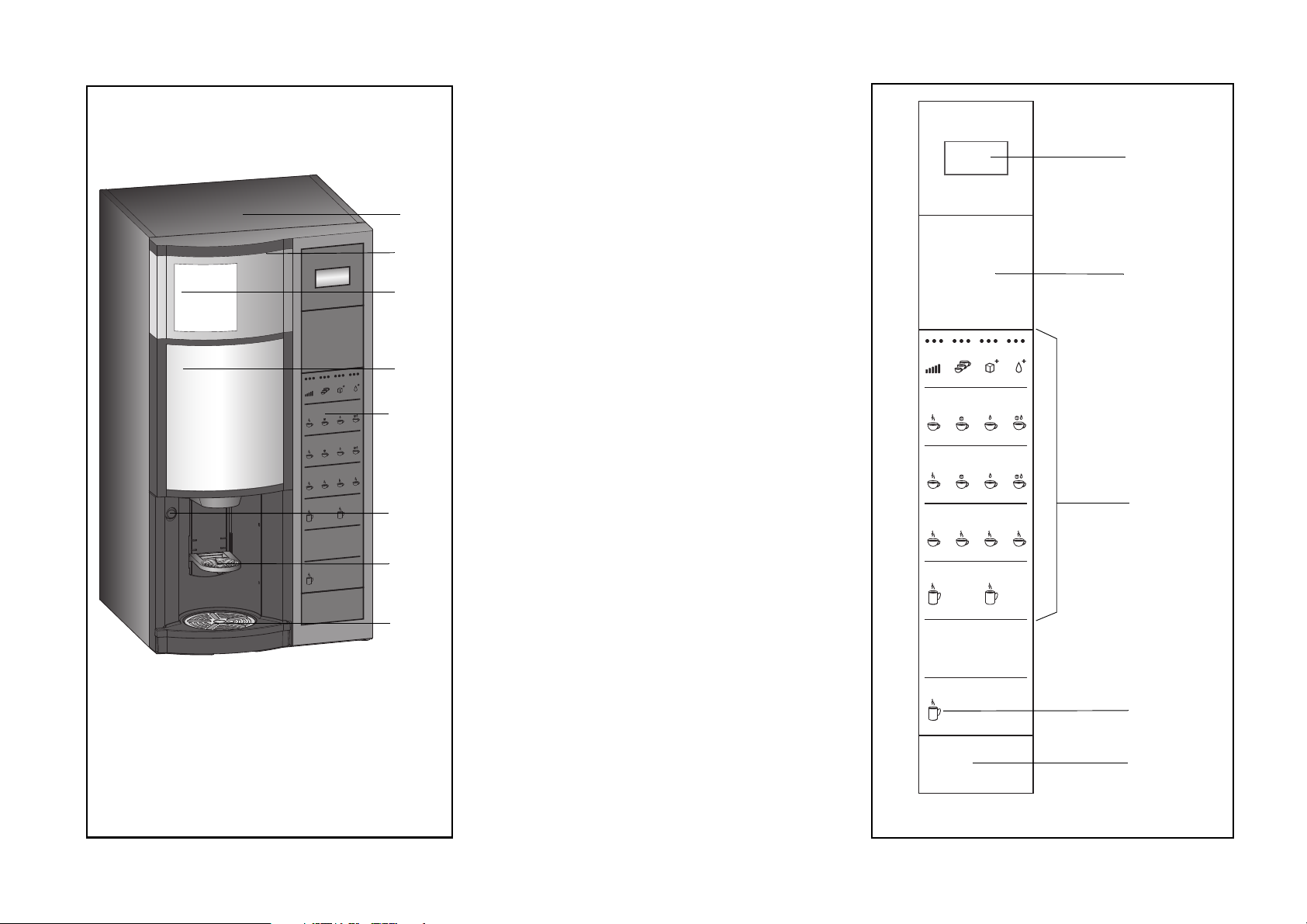
Machine front (fig 1.):
1 Cabinet
2 Door
3 Freshbrew ingredient canister
4 Advertising poster
5 Operating panel
6 Door lock
7 Cup carrier
8 Pot platform
Operating panel (fig.2):
1Display
2 Payment panel
3 Selection panel
4 Pot panel/Discount key
5 Optical interface
1
2
6 FB 7100 PLUS 10.2011
Page 11
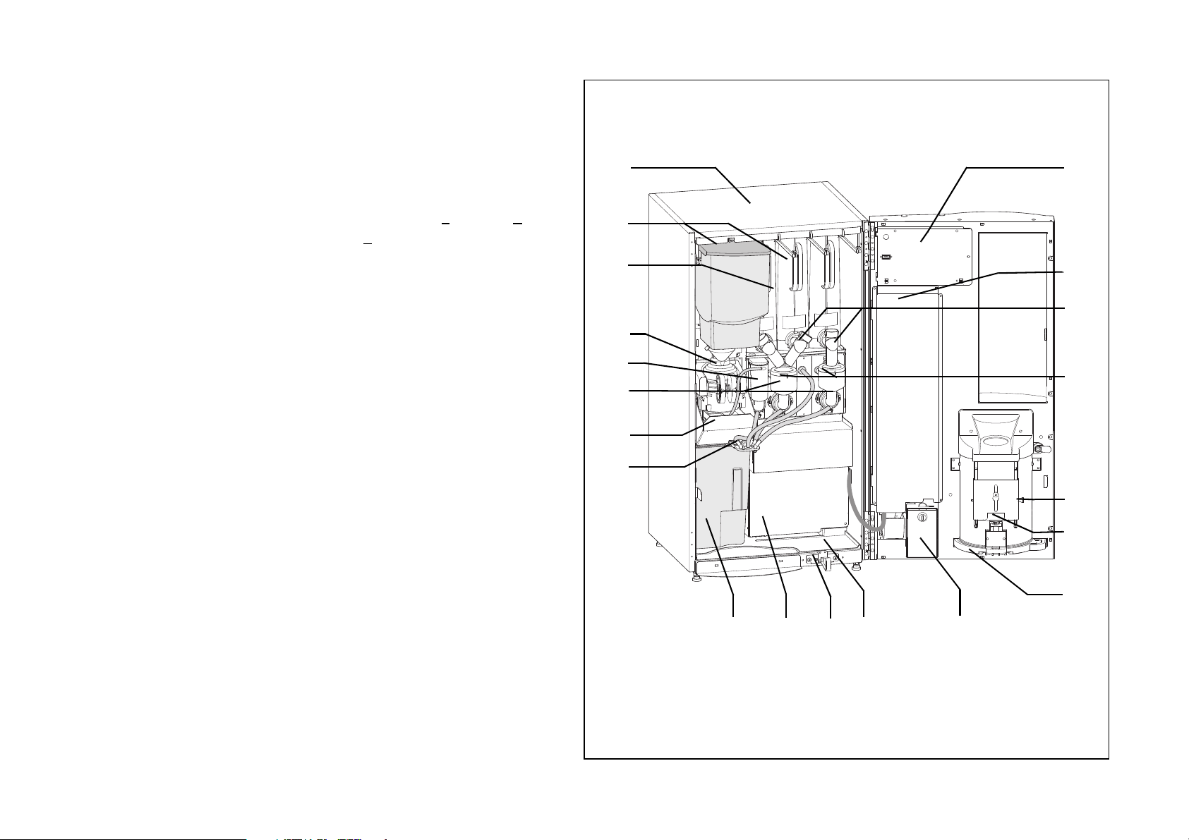
Machine cabinet (fig. 3):
1
2
4
5
6
3
10 1211
8
7
9
20
14
15
16
18
17
19
13
Product presentation
1 Cabinet
2 Ingredient canisters
3 Main switch
4Brewer
5 Diffuser / Coffee mixer
6 Mixing funnels with
whipper housings
7 Holder for dispense head /
chute for solid coffee
waste
8 Dispense head
9 Solid waste container
10 Cover for boiler
11 Door switch
12 Base tray
13 Cash box
14 Drip tray
17 Mixing funnel hood
18 Outlet spouts
19 Cover for payment system
/ cover for selection panel
circuit board (SPC)
20 Cover for CPU
15 Lock for drip tray
16 Retaining pin for cup
carrier
3
10.2011 FB 7100 PLUS 7
Page 12
Operation
----CASH ACTION---*Cash collected
Manual filling
^ v Sel Esc
----SALES AUDIT---*Total number
Total turnover
^ v Sel Esc
----SALES AUDIT---*Total number
Total turnover
^ v Sel Esc
----SALES AUDIT---*Total number
Total turnover
^ v Sel Esc
----SALES AUDIT---*Total number
Total turnover
^ v Sel Esc
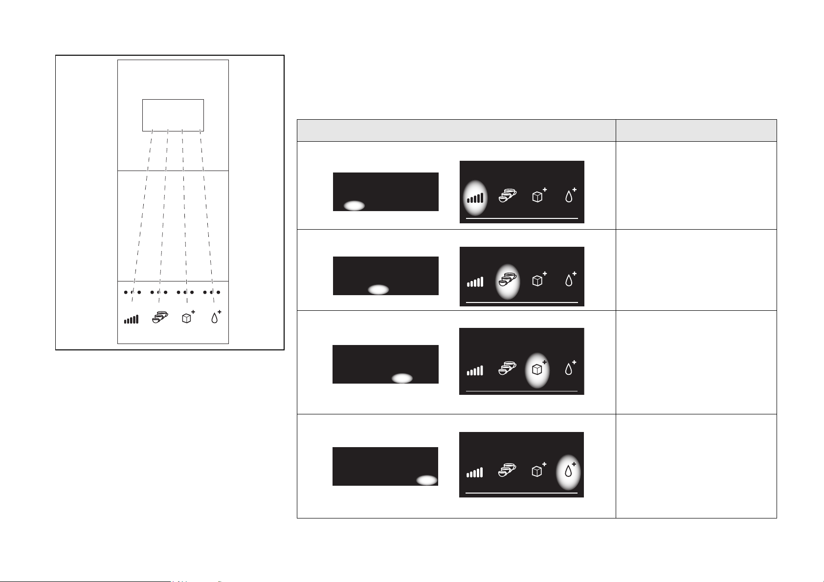
How to use the navigation buttons
This table describes how the four pre-selection buttons are used as navigation buttons.
Display Button Function
4
Navigation buttons
The four pre-selection buttons are used as
navigation buttons for retrieval of sales data,
settings, e.g. of prices, and activation of
service functions (fig. 4).
(See also diagram “SOverview of Operator
and Technicians functions” on page 13.)
‘Up’ button
Press this button to move
up one step at a time
‘Down’ button
Press this button to move
down one step at a time
‘Sel’ button’
Press this button to
• move one step to the
right
or
• activate a function, eg.
rinsing.
‘Esc’ button
Press this button to
• move one step to the left
or
• jump to the top of a row,
e.g. from “Turnover per
drink” to “Total turnover”.
8 FB 7100 PLUS 10.2011
Page 13
Operation
Reset cash audit
Continue?
*Reset counters
^ v Esc OK
Reset cash audit
Continue?
*Reset counters
^ v Esc OK
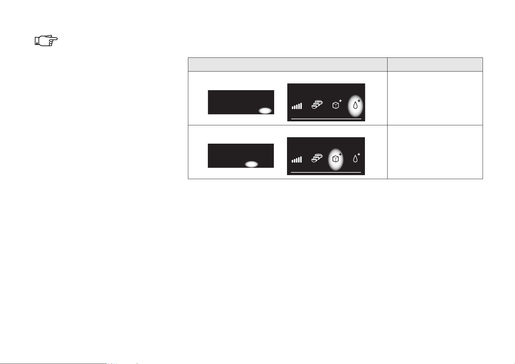
The functions of the buttons vary.
The ‘Sel’ button, for example, may
change to an ‘OK’ button to
confirm an action. The immediate
functions can always be read from
the bottom line of the display.
Alternative functions of the navigation keys:
Display Button Function
‘OK’ button
Press this button to
confirm an action, e.g.
resetting of counters.
‘Esc’ button
Press this button to exit a
function without activating
it, e.g. avoid resetting a
counter.
10.2011 FB 7100 PLUS 9
Page 14
Operation
Price: [Drink]
*Set price: xx.xx
(-) (+) -> OK
Price: [Drink]
*Set price: xx.xx
(-) (+) -> OK
Price: [Drink]
*Set price: xx.xx
(-) (+) -> OK
Price: [Drink]
*Set price: xx.xx
(-) (+) -> OK
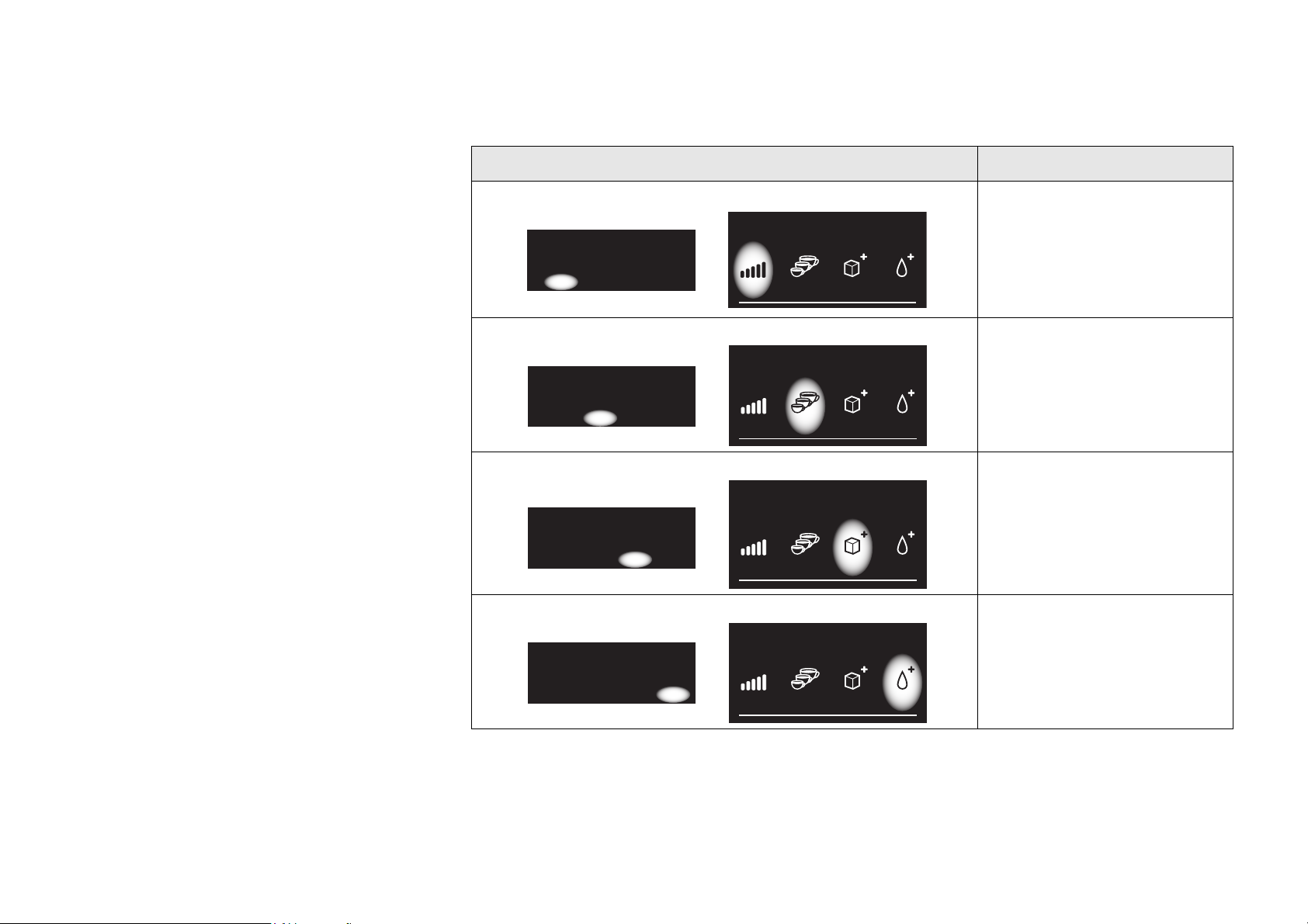
Settings buttons
In functions that require settings, for example
price settings, the functions of the four preselection buttons change accordingly.
This table describes how the four pre-selection buttons are used to enter or change numbers.
Display Button Function
‘Minus’ button
Press this button to
decrease a numeric value
in increments of one.
‘Plus’ button
Press this button to
increase a numeric value
in increments of one.
‘Next’ button
Press this button to
continue to the next digit,
e.g. in price setting
functions.
10 FB 7100 PLUS 10.2011
‘OK’ button
Press this button to save
changes to settings in the
system.
Page 15
Multibrew
Pot panel (Multibrew)
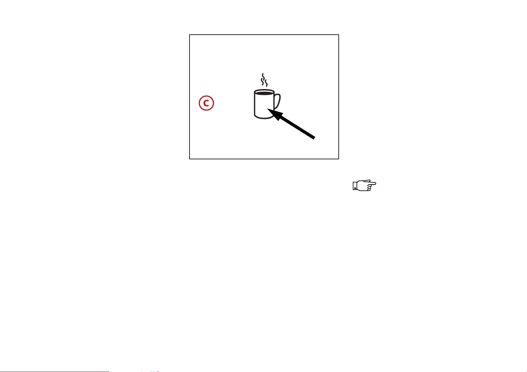
How to brew a pot: (fig. 5)
• Enter password
• Press multibrew button as many times as
the number of cups you want in the jug.
A predefined number, eg. ‘4’ is shown in
the display.
• Place a pot on the pot platform.
Operation
• Press the pot button once or more times
for the desired number of portions.
Pressing again will increase the displayed
counter by one, up to the maximum value
(15 or lower, set by the technician).
When the counter reaches the maximum
value and the pot button is pressed once
more, the counter restarts at the
predefined number.
5
• If the machine is not set to free vend,
insert a card with sufficient credit, or
insert an amount of coins corresponding
to the value of the number of drinks
selected or a value above.
• Press the selection button for the wanted
drink.
The display steps back one number each
time a portion is dispensed, or if
‘optimised multibrew’ is active a
progressive bar is shown.
• Remove the pot when the drinks have
been dispensed.
A pot brew in progress can be
stopped immediately, simply by
pressing the cancel button ©.
The pot sensor may not register a
pot of transparent material, eg.
glass.
10.2011 FB 7100 PLUS 11
Page 16
Operation
Multibrew
678
Discount lock
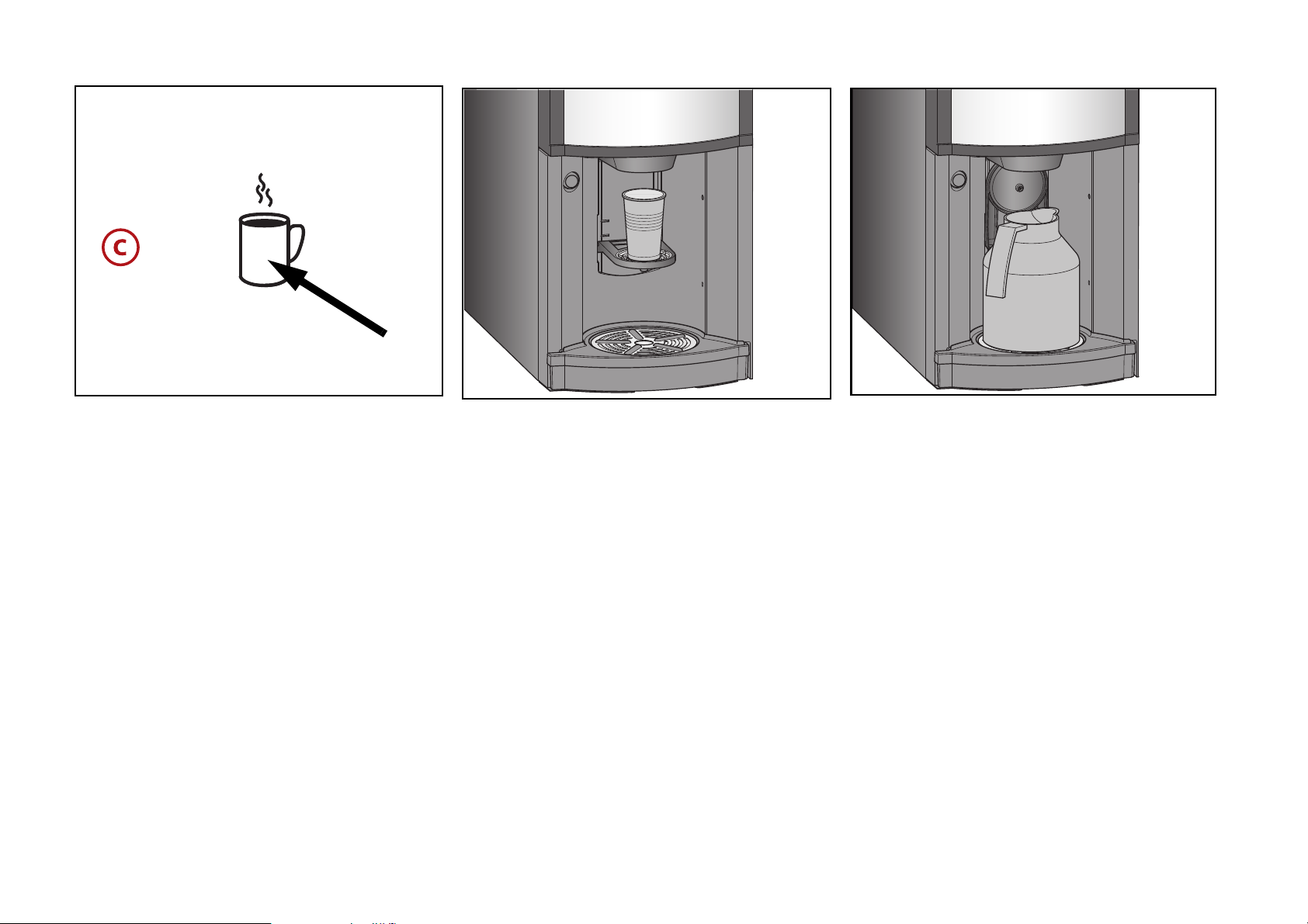
How to use discount lock: (fig. 6)
Drink to be dispensed in cup: (fig. 7)
When using the discount lock, drinks can be
dispensed at a preset discount. The discount
lock can be used for single drinks and for
pots.
If you want one or more drinks at a discount:
• Press the multibrew button and insert the
password needed to avoid free drink
dispensing.
12 FB 7100 PLUS 10.2011
• place a cup on the cup platform
• Press the selection button of the desired
drink.
• After dispensing, remove the cup.
•
Drink to be dispensed in pot: (fig. 8)
• place a pot on the pot platform and press
the pot button until the display shows the
desired number of dispensings.
• Press the selection button of the desired
drink
• After dispensing, remove the pot.
Page 17

SOverview of Operator and
Test
Complete selections
Operator
Filling/Clean
Rinse
Rinse Total Machine
Rinse With Stop FB1
Rinse Water
Counters
Sales Audit
Total number, nres
Total turnover,nres
Total number, res
Total turnover,res
No. per drink, nres
No. per drink, res
Turn. p. drink,nres
Turn. p. drink,res
MB per drink, nres
MB per drink, res
No. per group, nres
No. per group, res
Turn. p. group,nres
Turn. p. group,res
Card audi
t
No. per drink, nres
No. per drink, res
Turn. p. drink,nres
Turn. p. drink,res
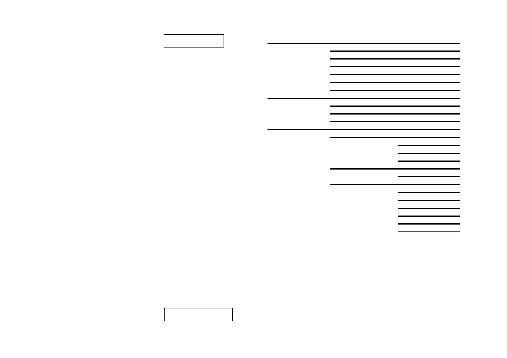
Operator menu - version 7.
4
Continued on next page
Technicians functions
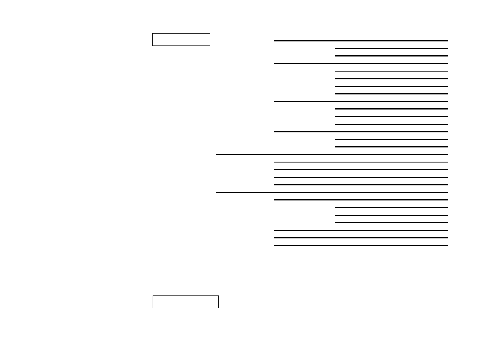
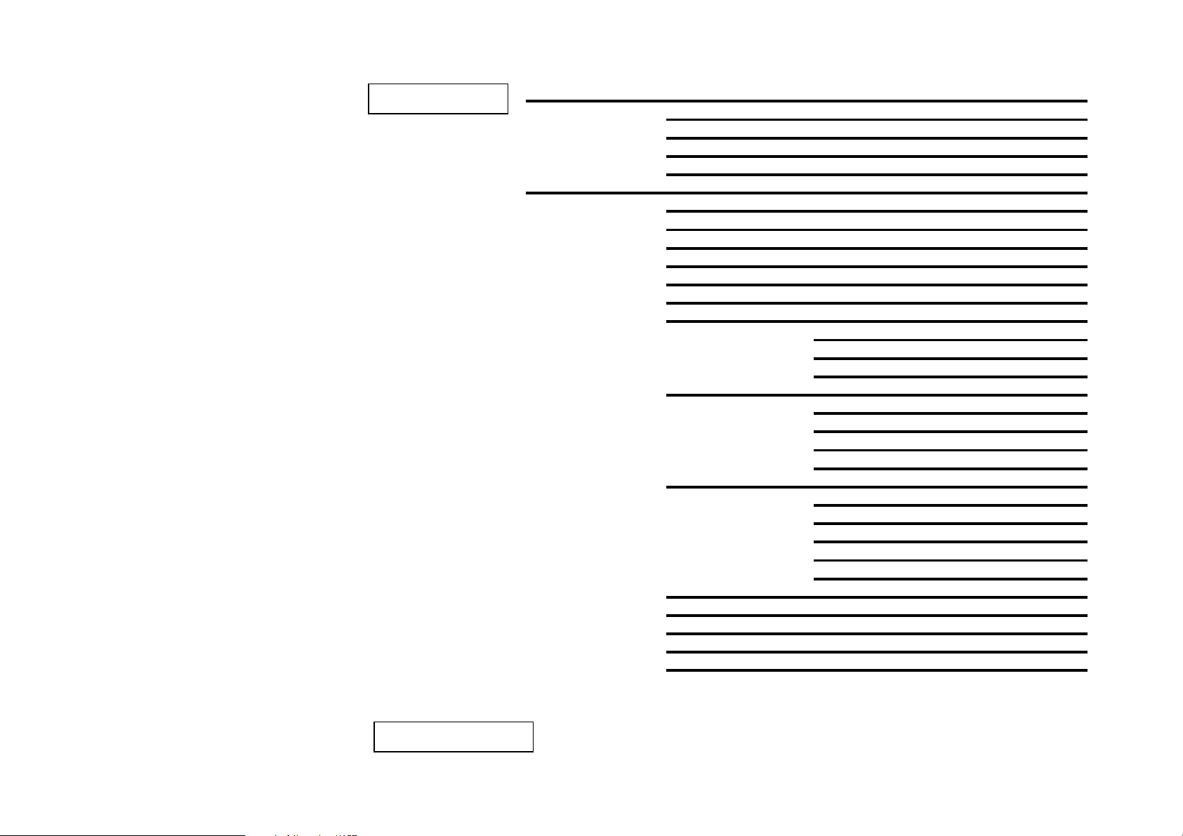
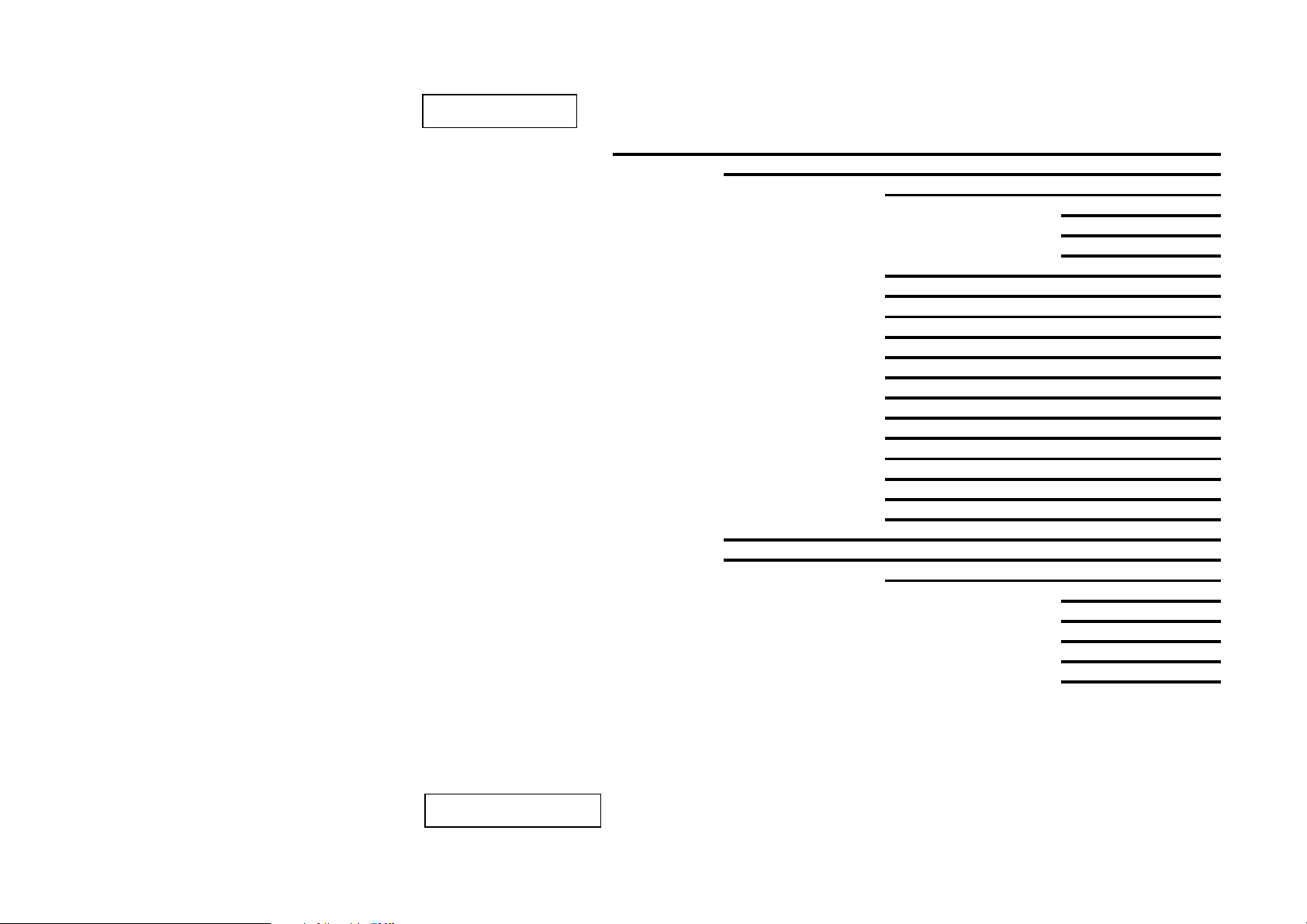
This diagram shows a total view of the
functions of the Operator and
technicians menu (version 7.4).
All functions are reached using the
four preselection buttons to navigate
through the menus.
The operator and/or the technicians
menus are password protected to
prevent unintentional and
unauthorized use.
As requested by the customer,
access through password is
requested either
- when entering the operator menus,
or
- when entering the technicians
menus.
(See explanation on previous pages).
Operation
10.2011 FB 7100 PLUS 13
Page 18

Operation
Cash Audi
t
Money to tube
s
Money to cash bo
x
Number of tokens
Collected mone
y
Manually filled
Manually delivere
Value overpa
y
Dispensed change
Cashless Audit
Revalued amount
Free vend audi
t
Total no. ,nres
Total no. ,res
No. per drink, nres
No. per drink, res
No. per group, nres
No. per group, res
MB. discount audi
t
MB. number, nres
MB. turnover, nres
MB. number, res
MB. turnover, res
Discount key audi
t
D.Key number ,nres
D.Key turnov. ,nre
s
D.Key number ,res
D.Key turnov. ,re
s
Time Discount audit
T.Disc number ,nres
T.Disc turnov.,nres
T.Disc number ,res
T.Disc turnov.,res
Continued on next page
Diagram continued
14 FB 7100 PLUS 10.2011
d
Page 19
Operation
Step prices audi
t
SP. turnover ,nres
SP. turnover ,res
Test Audit
Test no. ,nres
Test no. ,res
No. per group, nres
No. per group, res
Reset Counters
Reset sales audi
Reset cash audit
Reset Test audit
Printing
Not Resetable
Resetable
Cash action
Cash collected
Dispense coins
Manual filling
Reset tube contents
Basic operations
Change prices
Global price
Price per drink
Step prices
Change quantities
Drink On/Off
Change group
Continued on next page
Diagram continued
t
10.2011 FB 7100 PLUS 15
Page 20
Operation
Service information
Event log boo
k
Reset log book
Program versions
Show menufile ver.
Machine settings
Set Freevend,global
Set Beep mode
Clock on displa
y
Temp. on displa
y
Set date and time
Key discoun
t
Time discount
Set Time discount
Set Day(s)
Set Time
Machine Info
Machine Code
Operator Code
Show Install. Date
Set Install. Date
Energy saving
Save Energy On/Of
f
Set Day(s)
Set Time
Set Temperature
Set Doorligh
t
Set counters on/off
Selfcheck setting
Gr. counters on/off
100% discount mode
Use EVA-DTS events
Diagram continued
Continued on next page
16 FB 7100 PLUS 10.2011
Page 21
Operation
Technician
Adjust system
Calibration
Ingredient
Valve
Cold water
Temperatures
Lower cup sensor
Cup sensor status
Brewing profile
Pot Sensor On/Off
Cold water valve
Undosed water
Softener counter
Ex.WaterCirculation
Set Rinse Timeout
Brewer assembly chk
Clogged filter chk
Global dr. scaling
Reset relationship
Change Comm. route
Closed door
Serial XModem
Serial EDDCMP
IR XModem
IR EDDCMP
Back to terminal
Technician Menu - version 7.
4
Diagram continued
Continued on next page
10.2011 FB 7100 PLUS 17
Page 22

Operation
Opened doo
r
Terminal Mode
Configurator Mode
Set baud rate
Payment settings
Single/Multi vend
Set payment typ
e
Set max credit
Set max change
Obligation to bu
y
Coin inhibi
t
Low change inhibi
t
A
udit unit Ext/In
t
Exact change eq.
Exact change offset
Keyboard inhibi
t
Price mode
Price to inde
x
Zero vend mode
Zero vend inde
x
Revalue
Immediate change
Currency code(auto)
Currency code(man)
Coin validato
r
Decimal point pos.
Freevend count.mode
Delayed Paymentmod
e
Set Cash Sale
Sess. Complete Mode
A
utom Cashaudit Res
Pricelist Start Nr.
Diagram continued
Continued on next page
18 FB 7100 PLUS 10.2011
Page 23
Operation
Multibrew settings
Preset value
Min value
Max value
Means of action
MB Discount
Optimised multibrew
Change config files
Set language file
Set recipe file
Set menu file
Diagnostics/Test
Overall functions
Wittlink test
Full dispense tes
t
Test vend
Cup handling
Sensor test
User interface
Button/Key tes
t
Display tes
t
Pre. sel. led tes
t
Door light toggle
Test Init.text
Coin return motor
Diagram continued
Continued on next page
10.2011 FB 7100 PLUS 19
Page 24

Operation
Water/power/heat
Water sensors
Pump on/off
Heater on/off
Fan on/off
Test whipper no. X
Test all whippers
Test valve no. X
Test all IN valves
Test IN motor no.X
Test all IN motors
Sigma brewer 1
Brewer positions
Move piston forward
Move piston back
Change password
GSM settings
GSM On/Off
PIN Code
Pre-Alarms
Set GSM Thresholds
Reset Pre-Al. cnt
Bank ID's
Reset GSM relations
DaylightSavin
g
UP KEY Utilit
y
Setup files
Statistics files
Diagram continued
20 FB 7100 PLUS 10.2011
Page 25
Operation
If you want to .. then go to ..
Perform a rinse function Step 5
Read the counters Step 8
Proceed to the menu functions Step 9
Return to vend mode Step 6
If you want to .. then go to ..
Perform a rinse function Step 5
Perform a test vend Step 7
Read the counters Step 8
Proceed to the menu functions Step 9
Short cuts
Some functions can be reached through short
cuts.
A short cut is a one-step way to select often
used functions, which would otherwise
require several steps through the Operator
menu.
The following functions can be reached via
short cuts:
• Rinse function, see “Rinsing machine” on
page 35.
• Test function, see “Last check” on
page 361).
• Counters function, see “Calling and
resetting counters” on page 56.
• Menu, see “SOverview of Operator and
Technicians functions” on page 13.
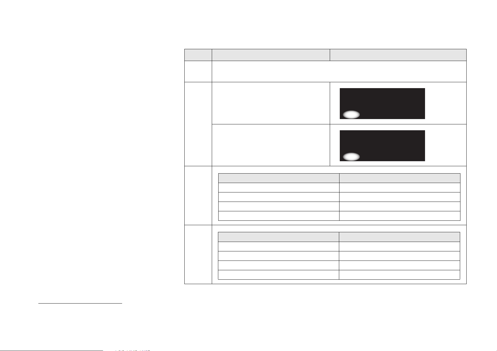
How to use the short cuts:
Step Action Display
1 • Open and close door.
• Wait and turn to the display.
2 • If the display shows the following
short cuts selection window, then go
to step 3.
• If the display shows the following
short cuts selection window, then go
to step 4
3
-----SHORTCUTS----*(1)=Rinse 3=Counter
(2)=Return 4=Menu
(1) (2) (3) (4)
-----SHORTCUTS----*(1)=Rinse 3=Counter
(2)=Test 4=Menu
(1) (2) (3) (4)
1. This short cut is not present in all machines.
10.2011 FB 7100 PLUS 21
4
Page 26
Operation
-------RINSE------*Rinse total machine
Rinse With Stop FB1
-----SHORTCUTS----*(1)=Rinse 3=Counter
(2)=Return 4=Menu
(1) (2) (3) (4)
-------TEST------*Complete selections
----SALES AUDIT--*Total number, nres
Total turnover,nres
Step Action Display
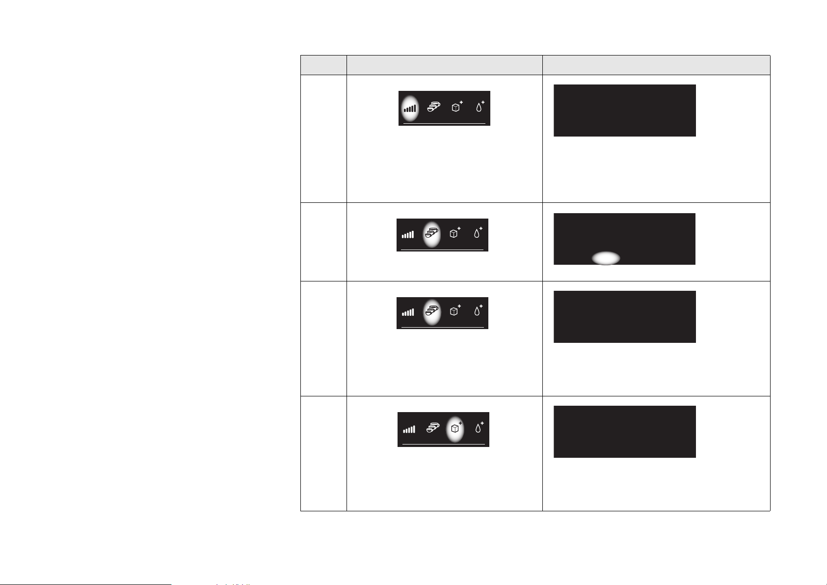
5
6
7
Press “1”
and, if open, close the door to go directly to
the rinse functions menu.
From here you can select one of the
available rinse functions.
Press “2”
With closed door, the machine returns to
vend mode.
Press “2”
and, if open, close the door to go directly to
the test vend functions.
From here you can select one of the
available test vend functions.
v Sel Esc^
v Sel Esc^
22 FB 7100 PLUS 10.2011
8
Press “3”
and, if open, close the door to go directly to
reading the counters.
From here you can select one of the
available counters.
v Sel Esc^
Page 27
Step Action Display
--MENU SELECTION-*Operator
Technician
Operation
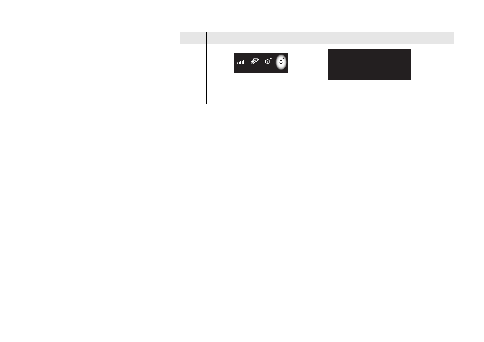
9
Press “4”
and, if open, close the door to go directly to
the menu selections.
From here you can select one of the menus
v Sel Esc^
10.2011 FB 7100 PLUS 23
Page 28

Operation
Additional Features
The machine can be set to either
multi-vend or single-vend.
Multi-vend
• The machine can be set to enable
selection of several drinks, one after the
other, from only one payment action by
coins or card.
Single-vend
• The machine can be set to return coins /
release payment card after each drink
selection.
24 FB 7100 PLUS 10.2011
Page 29

General instructions
Cleaning and maintenance
• All items of the schedules in this chapter
should be carried out at the following
intervals:
Regular cleaning: Every time replenishing
of ingredients is required
Deep cleaning: Once a week.
Occasional routines: Once a month.
• If the schedules hereafter are not carried
out as indicated, it will influence the
reliability of the machine, which will not be
covered by guarantee, and there might
arise HACCP risks, for which the
suppliers of machine and ingredients
cannot be held responsible.
• Read the corresponding sections in the
operator manual to enable you to exactly
perform the individual tasks.
Make sure that all components are
installed correctly after the cleaning procedure.
• Use only cleaning agents approved by the
food industry, or the supplier of the
vending machine.
• Do not use aggressive or abrasive
cleaning agents.
• As well as cleaning every week and/or
every 1,000 dispensings, a nylon brewer
filter or the gasket for a metallic filter must
be replaced after a certain amount of
selections, even if apparently still efficient:
Nylon filter for coffee: every 25,000
dispensings
Gasket for metal filter: every 50,000
dispensings.
Be sure to use correct nylon filter
for tea / coffee brewing:
- nylon tea filter has a red seal.
- nylon coffee filter has a neutral
white seal.
Clean the inside and outside of the
vending machine by using a clean
damp cloth, and do not splash it.
10.2011 FB 7100 PLUS 25
Page 30

Cleaning and maintenance
Maintenance routines
Schedule for regular maintenance routines
Interval Type of work / Check Tools / Materials for the job
Regular:
Every time replenishing
of ingredients is
required
Opening the door
Filling the ingredient canisters
Filling the freshbrew ingredient canister
Removing and emptying the solid waste container
Cleaning the cup carrier
Cleaning the drip tray
Cleaning the machine interior and exterior
Mounting the cleaned parts
Rinsing machine
Last check
1 bucket of hot water (60-80°C) with cleaning
agent.
1 bucket of clean warm (min. 40°C) water
Soft clean cloths or paper towels
Ingredients
26 FB 7100 PLUS 10.2011
Page 31

Schedule for deep and occasional maintenance routines
Interval Type of work / Check Exchange kit (hygiene kit)
Cleaning and maintenance
Deep:
Once a week.
Opening the door
Filling the instant ingredient canisters
Filling the freshbrew ingredient canister
Disconnecting the machine
Cleaning the ingredient waste tray and the instant
ingredient dispensing system components
Cleaning the powder traps
Cleaning the diffuser / coffee mixer
Removing the coffee waste chute
Removing the dispense head
Cleaning the freshbrewer parts
Removing and emptying the solid waste container
Cleaning the base tray
Cleaning the cup carrier
Cleaning the drip tray
Cleaning machine interior and exterior
Mounting cleaned parts
Mixing funnel hoods
Instant ingredient mixer units with whipper wheels
and sealing rings
Powder traps
Diffuser / coffee mixer (option)
Hood for diffuser
Whipper wheel for coffee mixer (option)
Dispense head with outlets and hoses
Brewer cylinder with mixing funnel, mixing funnel
hood and valve
Filter and support for filter
Scraper
Cup carrier.
-----------------
All the above mentioned parts together with the
solid waste container, the drip trays as well as the
instant ingredient canisters are dishwasher-proof.
(max. 30 minutes at 60°C, max. 30 seconds at
80°C).
Rinsing and last check
10.2011 FB 7100 PLUS 27
Page 32
Cleaning and maintenance
Interval Type of work / Check Exchange kit (hygiene kit)
Occasional
Once a month
Cleaning the instant ingredient canisters
Cleaning the freshbrew ingredient canister
Replacing the filter roll
Rinsing / descaling the brewer
28 FB 7100 PLUS 10.2011
Page 33
Regular cleaning
9 10
Opening and disconnecting machine
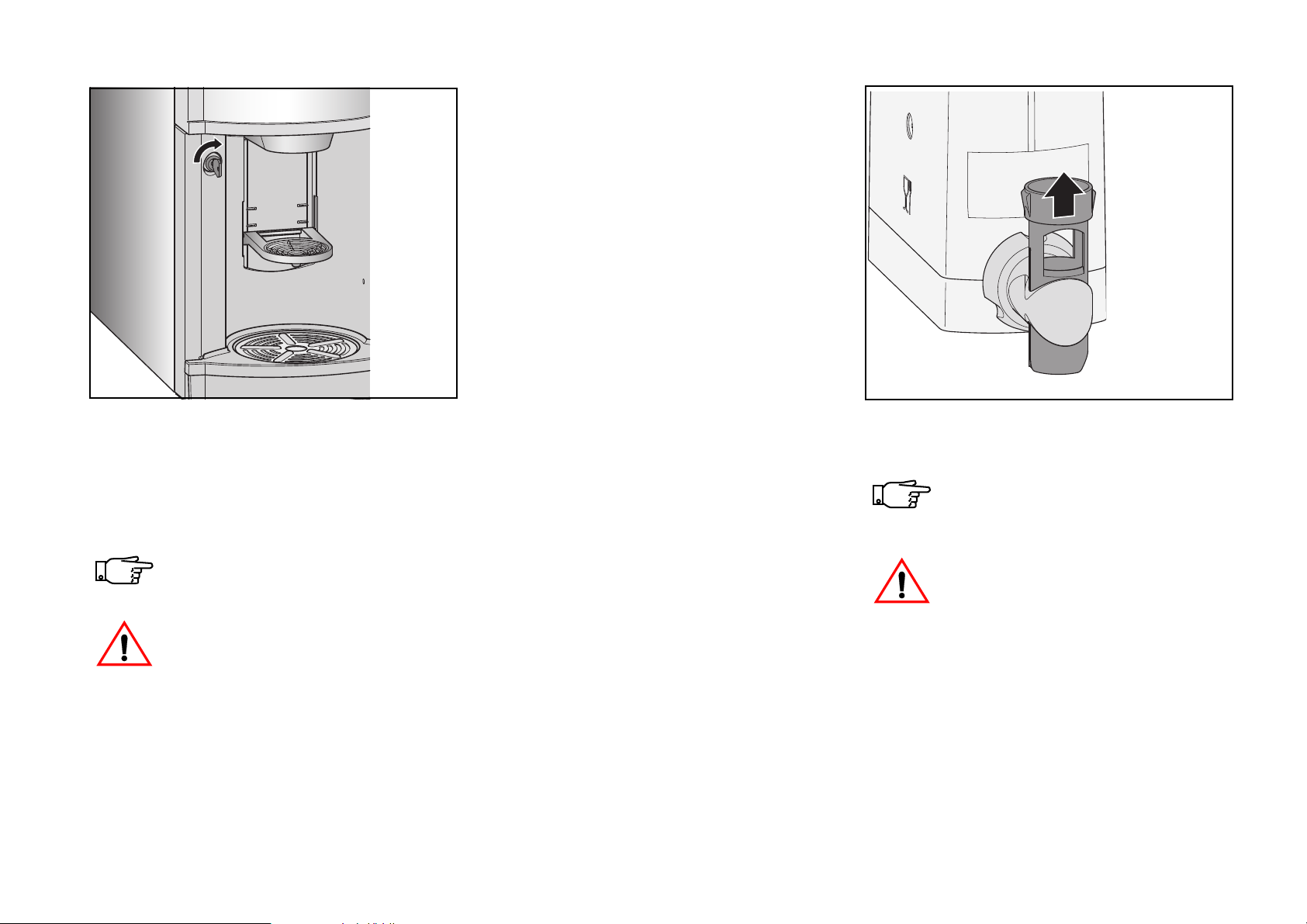
• Turn the door key clockwise in keyhole
(fig. 9) and open door.
The power to the brewer motor/s is
now disconnected.
If power is turned on, be careful not
to touch moving parts and electrical components!
10.2011 FB 7100 PLUS 29
Preparing for filling of canisters
• Pull forwards solid waste container.
• Pull base tray forwards.
Filling the instant ingredient canisters
Check ingredient level of instant ingredient canisters daily.
Replenish when necessary.
The instant ingredient canisters
should be labelled to avoid ingredients being poured into wrong canisters.
• Push the outlet tube upwards to close the
outlet spout of the wanted canister (fig.
10).
Page 34
Regular cleaning
11 12 13
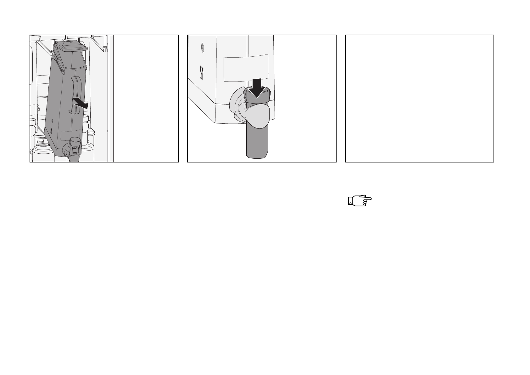
• Take the canister by the handle and pull it
forwards (fig. 11) until it is hanging freely
at its end stop in guiding rail. The lid is
automatically triggered open.
If required, lift the canister upwards and
pull forwards over the end stops in guiding
rail. Place canister on a plain, clean
surface.
• Push the outlet tube downwards to open
the outlet spout (fig. 12).
• Repeat procedure until the required
number of canisters have been filled.
• Push base tray back in place.
Filling the freshbrew ingredient canister
Fill according to use of ingredient.
• Pull forward the freshbrew ingredient
canister approximately 30 mm (fig. 13).
• Fill the canister with instant ingredient,
press lid slightly down and push back
canister in place.
30 FB 7100 PLUS 10.2011
Page 35
Regular cleaning
14 15
Removing the solid waste container
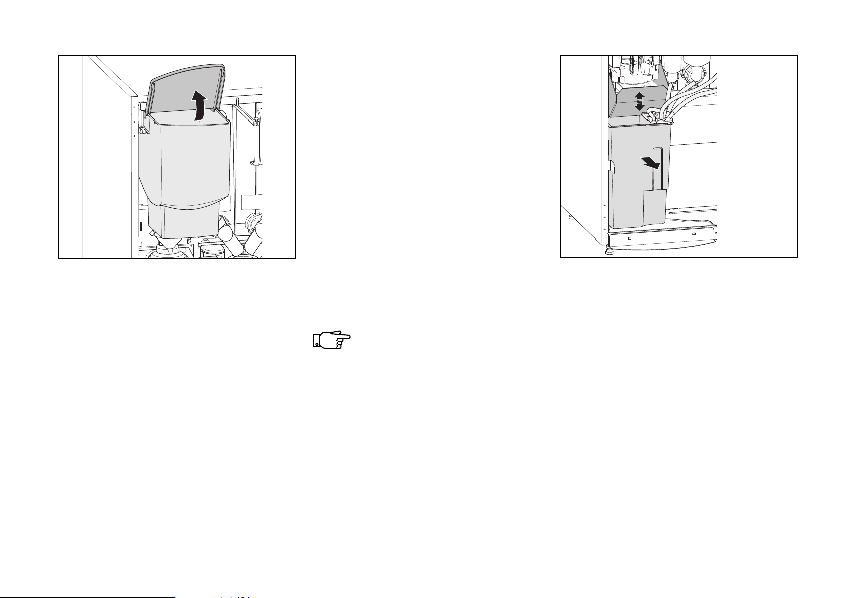
• Open the lid (fig. 14).
• Fill the canister with freshbrew product.
• Close the lid.
10.2011 FB 7100 PLUS 31
• Push back canister in place.
Check to make sure that the canister is locked in place.
• Shake the coffee chute up and down a
few times to release possible solid coffee
waste remnants into the waste container
(fig. 15.
• Take out the solid waste container
• Remove plastic bag from container, and
insert a new liner.
• Push base tray back in place.
• Wipe clean the area behind the solid
waste container.
Page 36
Regular cleaning
a
b
Cleaning the cup carrier
16 17
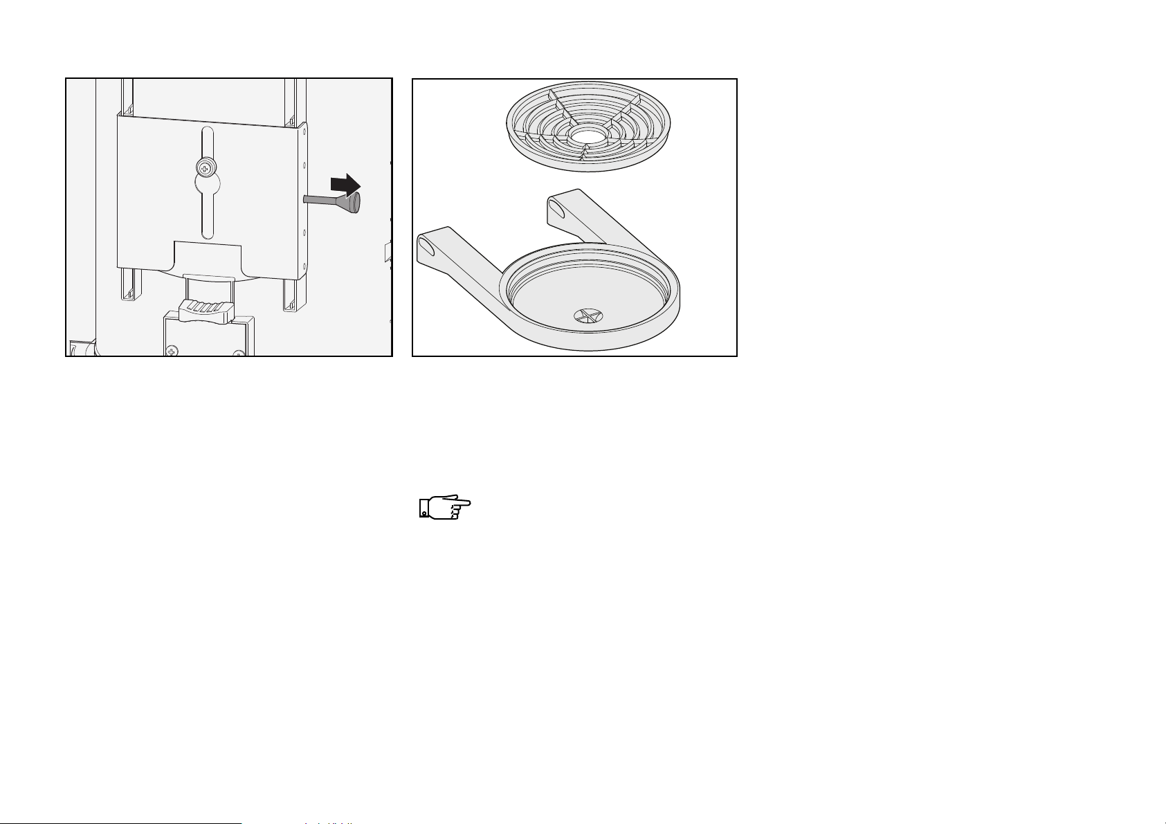
• Remove the cup carrier: Take hold of the
cup carrier with your right hand and with
your left hand remove the corresponding
retaining pin, situated on the rear side of
the cup station. (fig. 16).
32 FB 7100 PLUS 10.2011
• Disassemble cup carrier (fig. 17). Clean
the drip grid (a) and tray (b) in hot water
with cleaning agent and dry parts.
The complete cup carrier is dishwasher-proof.
• This machine could be delivered with an
anti-cross contamination system in order
to have the same outlet for coffee and
water and to avoid any spillage of coffee
into the hot water for tea.
Page 37
Regular cleaning
a
18 19 20
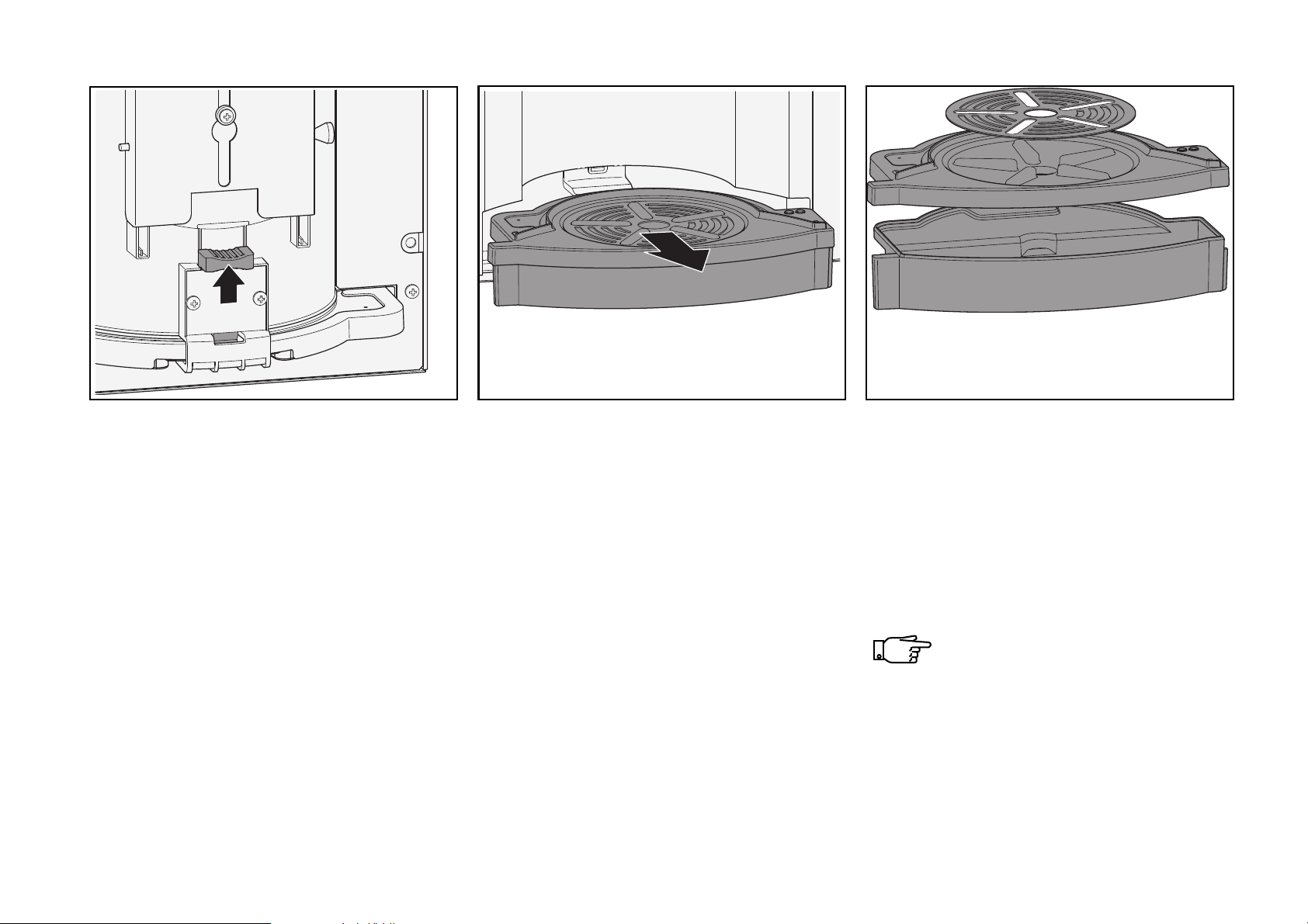
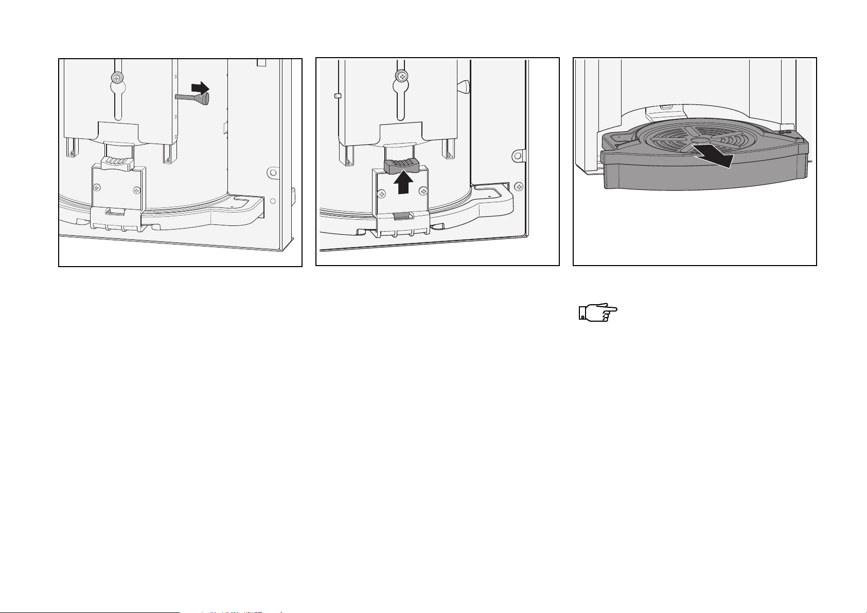
Unlocking the drip tray
• If locked, pull upwards lock for drip tray
(fig. 18), situated on the rear side of the
cup station.
10.2011 FB 7100 PLUS 33
Cleaning the drip tray
• Take hold of the drip tray with one hand
and pull it forwards in a gentle movement.
(fig. 19)
• Remove drip grid from lid.
• Remove the lid and empty the tray.
• Clean drip grid (a), lid and tray in hot
water with cleaning agent and wipe parts
dry (fig. 20).
Wipe sensor (fig. 20,a) in lid dry.
Page 38
Regular cleaning
21
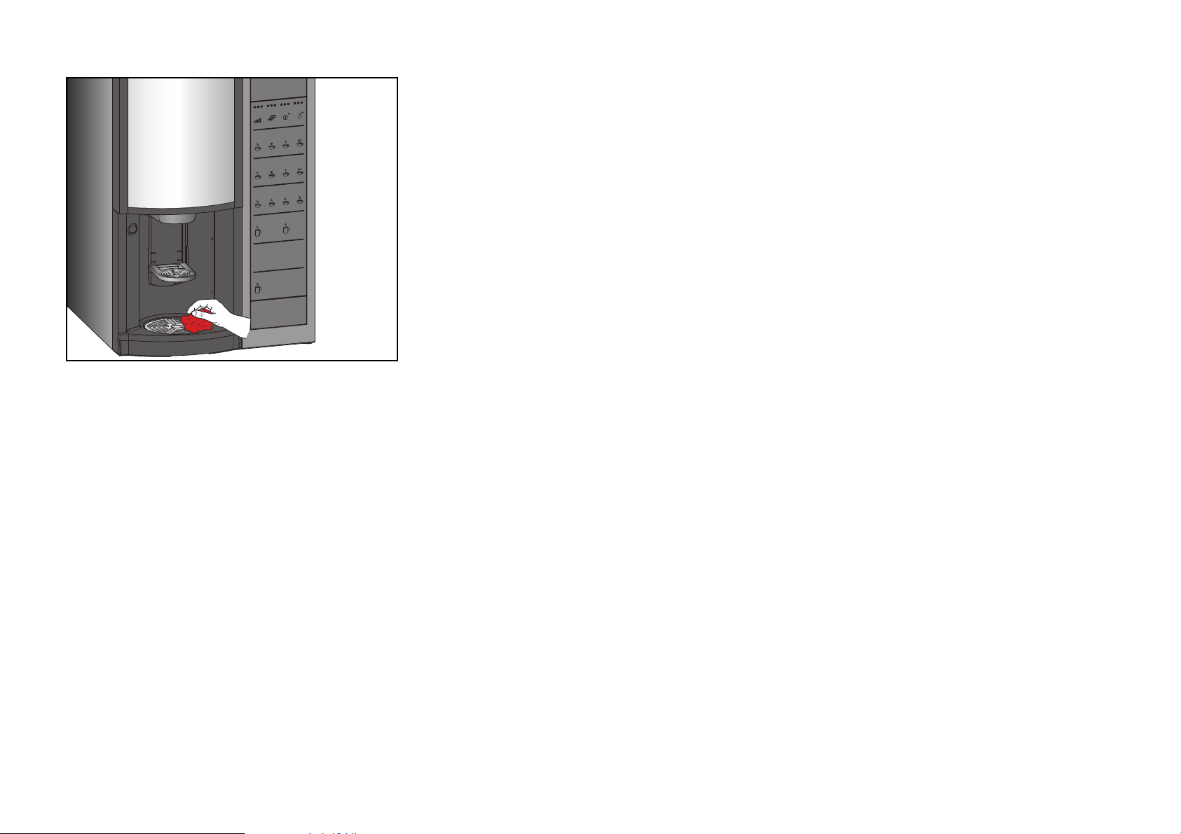
Cleaning inside and outside
• Clean the door and the housing inside
and outside, and finally the bottom with a
clean, damp cloth (fig. 21).
34 FB 7100 PLUS 10.2011
Mounting of cleaned parts
• Remount all parts.
Page 39
Regular cleaning
FB 7100
-----SHORTCUTS----*
(1) = Rinse
(2) = Test vend
Start
--MENU SELECTION--*Operator
Technician
^ v Sel ESC
Welcome
End
Rinse total machine
Sel
Esc
Wait until program has
finished.
Let the pot stay on
the platform and
repeat, min. one time.
1
Esc
--MENU SELECTION--*Operator
Technician
^ v Sel ESC
Navigation buttons
Up Down
Right
Left/Top
(1) (2) Menu
*Close door
*Place pot
on pot platform
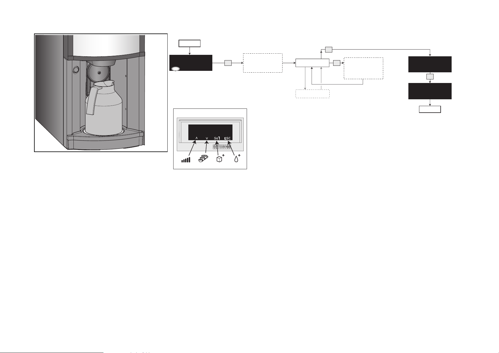
Rinsing machine
• Have an empty pot (min.1,5 l) ready
• Turn to the display and follow the
22
to place on the pot platform (fig. 22)
diagram to perform a machine rinse.
10.2011 FB 7100 PLUS 35
Page 40
Regular cleaning
Complete selections
DISPENSING TEST
Sel
Close door
Select a drink selection button, e.g.
'Wiener Melange'
After a complete
drink has been
dispensed,
remove cup
Open and close
door
--MENU SELECTION--*Test
Operator
^ v Sel ESC
End
Esc
Esc
* Select “Menu” -> “Enter Password” ->
“Test”
* Enter “Complete selections”
Esc
FB 7100
Last check
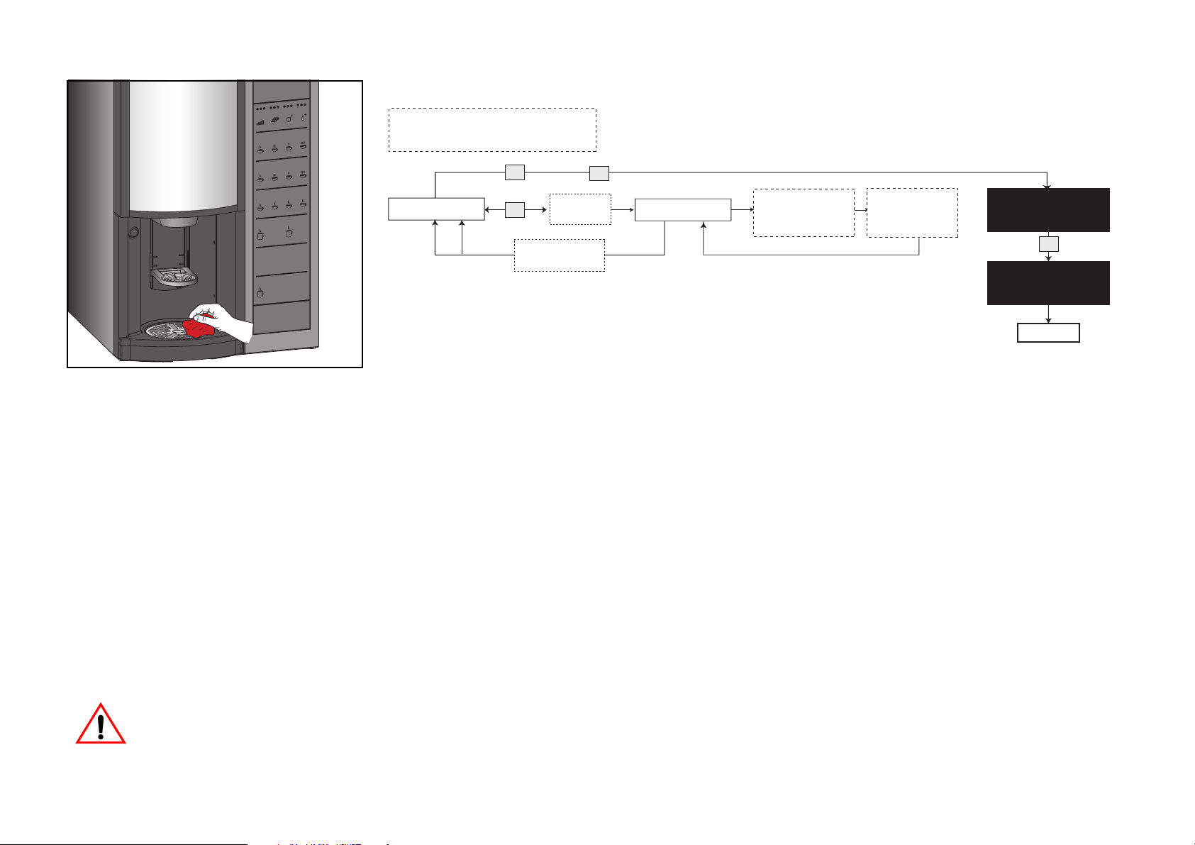
• Clean the machine with a damp
cloth on the outside (fig. 23).
• Perform a test dispensing by
pressing
- the selection button for coffee with
sugar or tea with sugar, or
- using the ‘Dispensing Test’ Option
in the operator menu (see
diagram above). In this case the
drink will not be included in the
Sales Audit counter ( See “Calling
and resetting counters” on
page 56.).
There is a risk of scalding
from hot water.
23
36 FB 7100 PLUS 10.2011
Page 41

24
Deep cleaning
SSHygiene kit
Opening and disconnecting machine
• In order to save time when cleaning and
filling it is recommended to have a
hygiene kit consisting of:
- mixing funnel hoods.
- instant ingredient mixer unit with whipper
wheels and sealing rings
- powder traps
- diffuser/coffee mixer (option)
- hood for diffuser
- whipper wheel for coffee mixer (option)
- dispense head with outlets and hoses
- brewer cylinder with mixing funnel,
mixing funnel hood and valve
- filter and support for filter
- scraper
- cup carrier.
10.2011 FB 7100 PLUS 37
• Turn the door key clockwise in keyhole
(fig. 24) and open the door.
The power to the brewer motor/s is
now disconnected.
If power is turned on, be careful not
to touch moving parts and electrical components!
Page 42
Deep cleaning
25 26 27
Filling the instant ingredient canisters
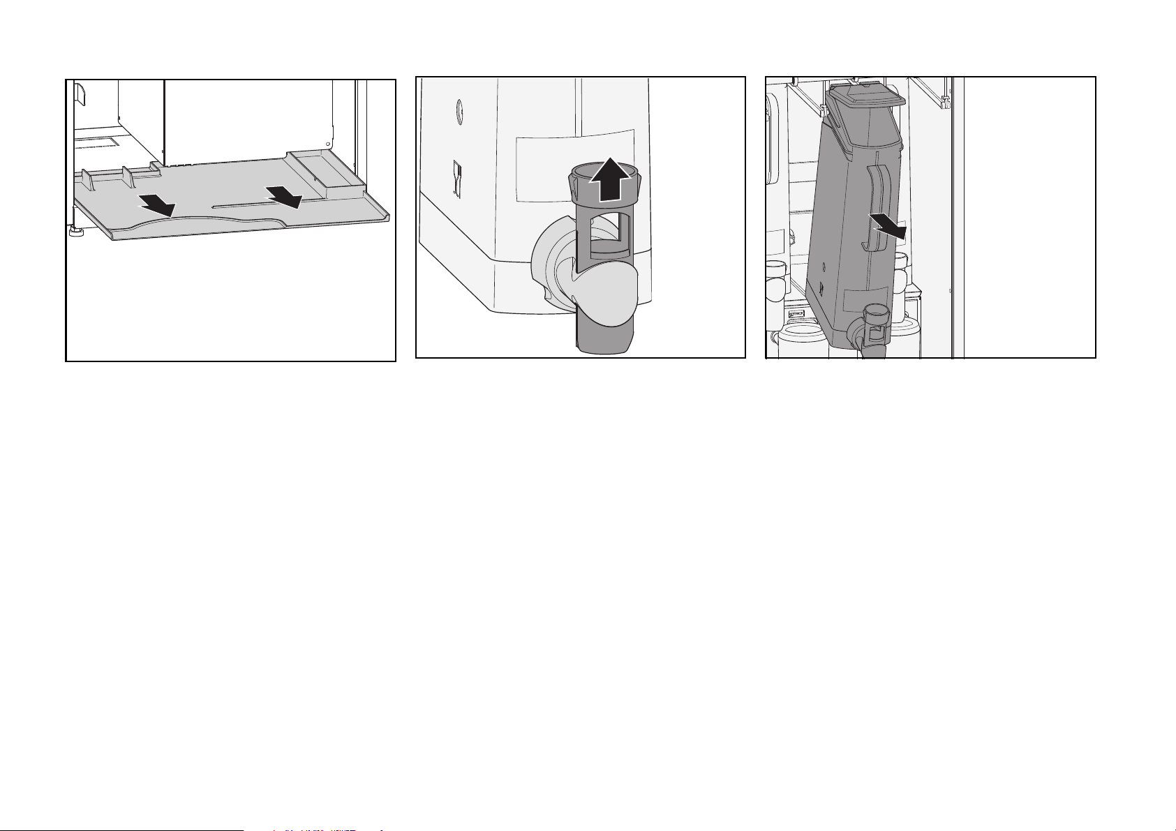
• Pull forwards the solid waste container.
• Pull forwards the base tray (fig. 25).
• Push the outlet tube upwards to close the
outlet spout of the wanted canister (fig.
26).
• Pull forwards and fill the instant ingredient
canisters one by one as described in
regular cleaning
(fig. 27).
• Leave the outlet spouts closed, and push
canisters back in place.
38 FB 7100 PLUS 10.2011
Page 43
Deep cleaning
28 29 30
Filling the freshbrew ingredient
Disconnecting machine
canister
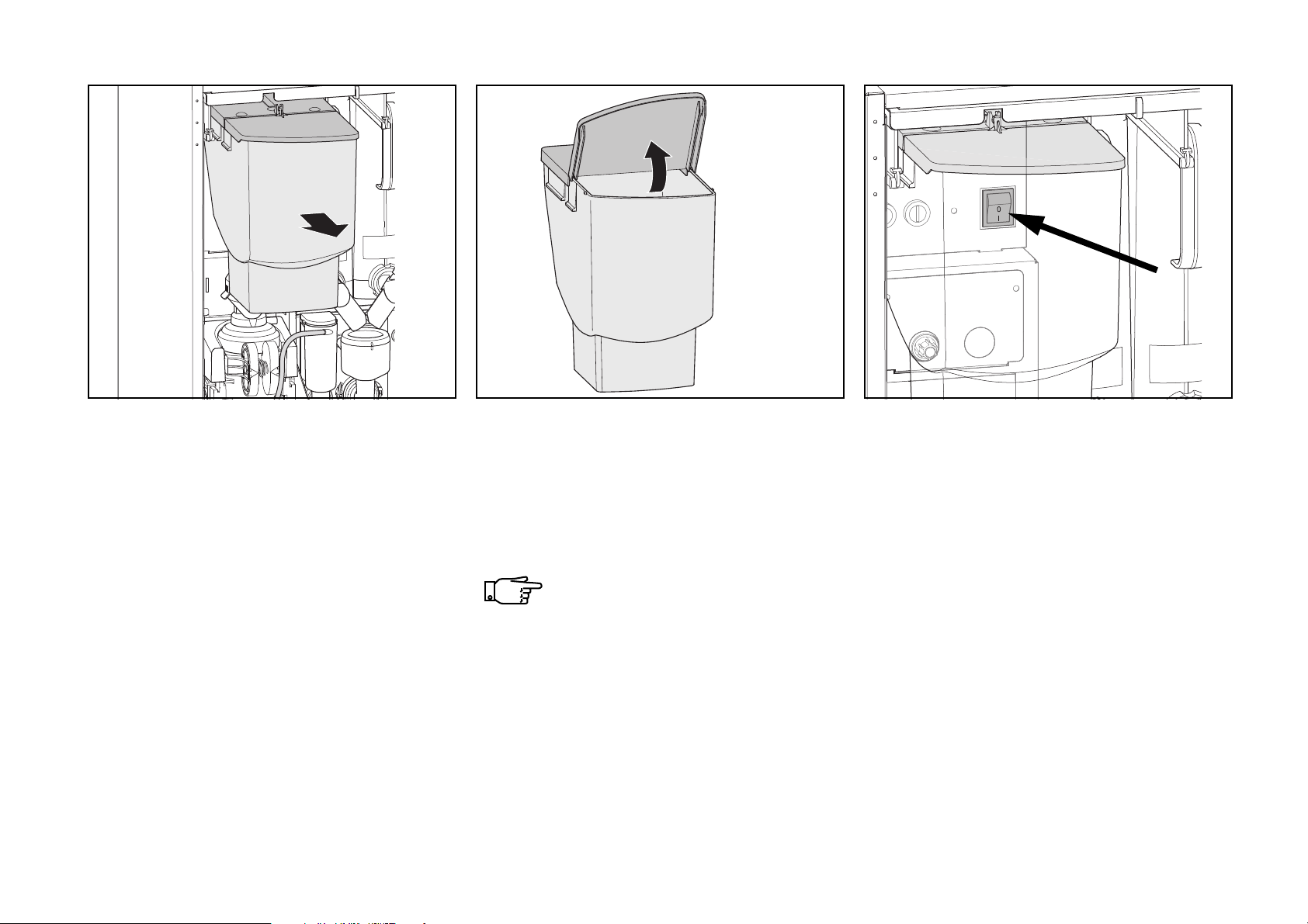
• Open the lid and fill the canister (fig. 29).
• Pull forward the freshbrew ingredient
canister approximately 30 mm (fig. 28).
10.2011 FB 7100 PLUS 39
• Close lid, and push the canister back in
place.
Check to ensure that the canister is
locked in place.
Do not use pressure to force more
coffee / tea into the canister as this
could damage the dosing system.
• Turn machine off with main switch located
behind the freshbrew ingredient canister
to the right side (fig. 30).
Page 44
Deep cleaning
31 32 33
Cleaning the ingredient waste tray
Cleaning the instant ingredient dispensing system components
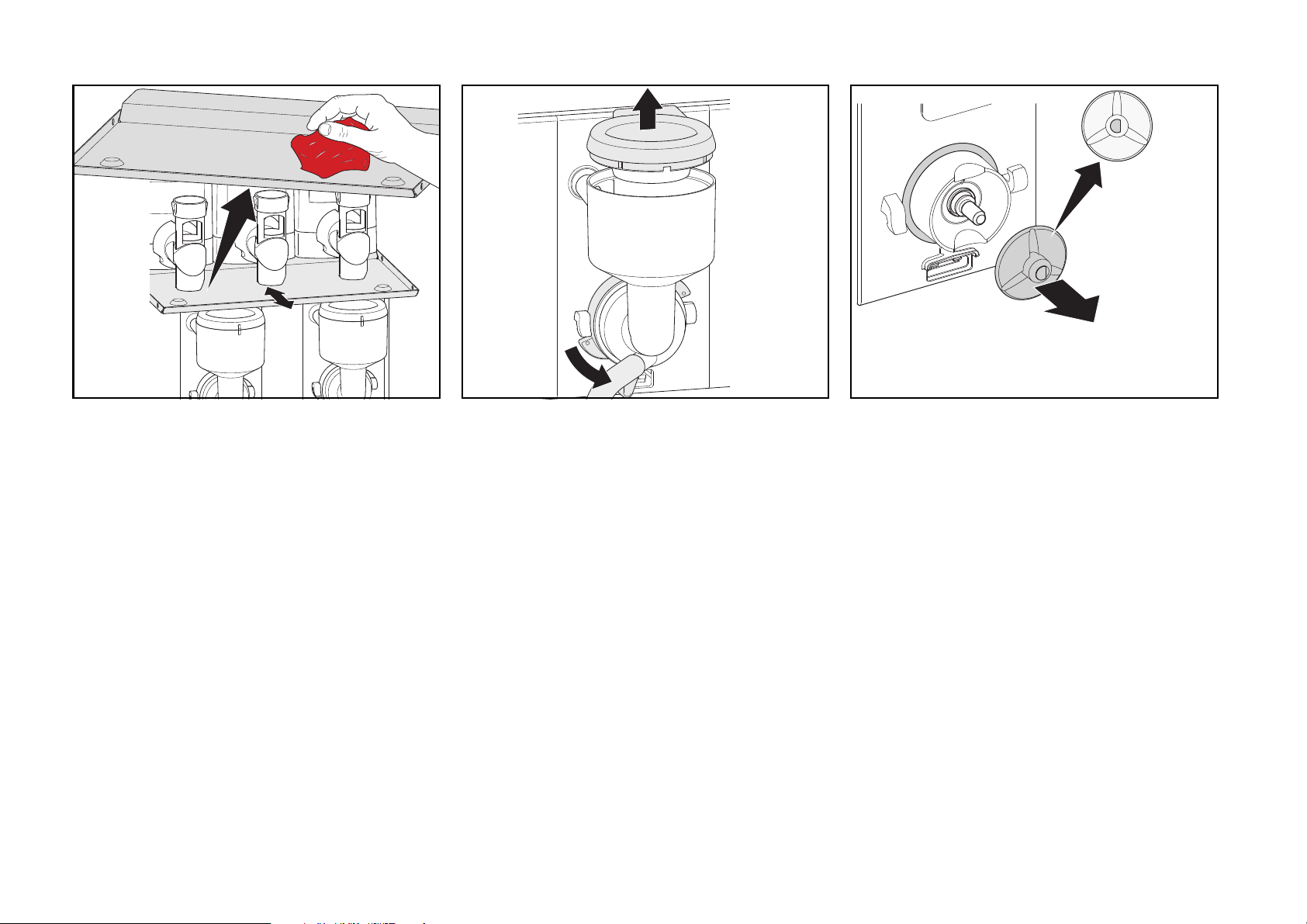
• Remove and wipe clean the ingredient
waste tray with a clean and moist cloth
(fig. 31).
• Relocate the ingredient waste tray.
40 FB 7100 PLUS 10.2011
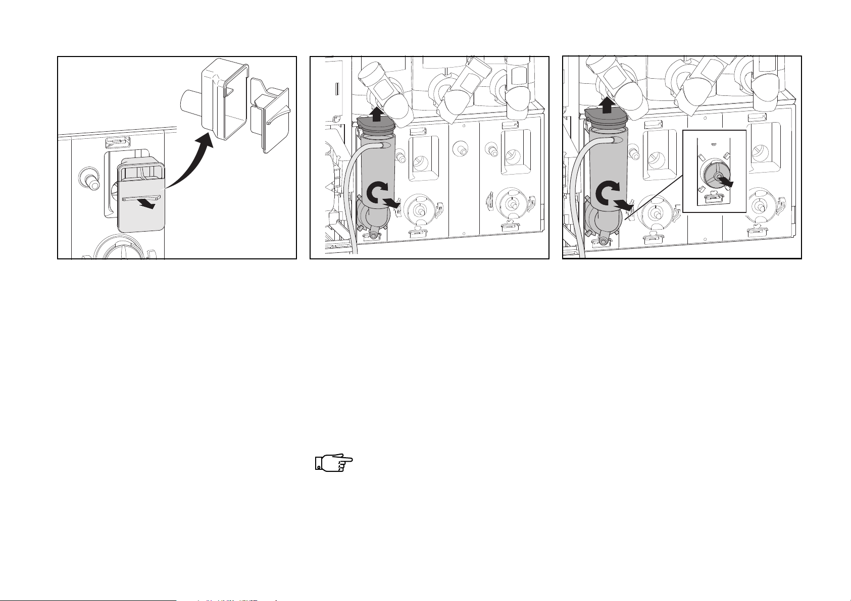
• Remove the mixing funnel hoods by lifting
off (fig. 32).
• Loosen locking rings of mixing funnels by
pressing release lever anti-clockwise and
pull out mixing funnel leaving hose back
on (fig. 32).
• Remove the sealing ring (fig. 33).
• Pull off the whipper wheel (fig. 33).
• Repeat procedure until all mixing funnels
have been removed.
Page 45
Deep cleaning
34 35 36
Cleaning the powder trap
• Take hold of the small handle on the
powder trap and pull out (fig. 34).
• Separate front and rear parts (fig. 34).
• Soak both powder trap components in hot
water with cleaning agent.
• Rinse parts in clean hot water, dry and
relocate items in reverse order.
10.2011 FB 7100 PLUS 41
Cleaning the diffuser
• Remove brewer hose from diffuser (fig.
35).
• Remove the hood for diffuser and the
upper sealing ring (fig. 35).
• Turn the diffuser clockwise and pull it off
leaving the outlet hose back on (fig. 35).
• Remove the lower sealing ring.
The machine is fitted with a diffuser or a coffee mixer.
Cleaning the coffee mixer
• Remove brewer hose from diffuser (fig.
36).
• Remove the hood for diffuser and the
upper sealing ring (fig. 36).
• Turn the diffuser clockwise and pull it off
leaving the outlet hose back on (fig. 36).
• Pull off the whipper wheel (fig. 36) and the
lower sealing ring.
• Soak all removed parts in hot water with
cleaning agent.
Page 46
Deep cleaning
37 38 39
Removing the dispense head
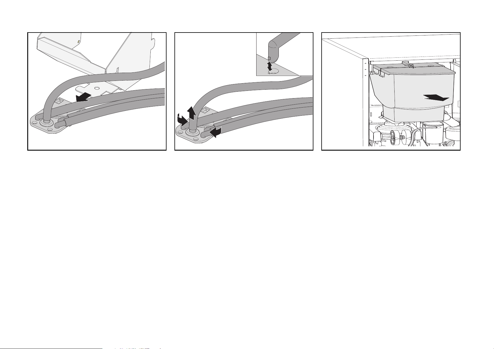
• Remove the dispense head by pulling it
forwards (fig. 37).
42 FB 7100 PLUS 10.2011
Removing the outlet hoses
• Remove hoses with spouts from dispense
head: turn each spout until its locking tab
can be released through the notch of the
hole in dispense head and lift off the spout
(fig. 39).
Removing the coffee waste chute
• Shake the coffee chute up and down a
few times to release possible solid coffee
waste remnants into the waste container.
Lift off and remove the coffee waste chute
(fig. 39).
Page 47
Cleaning the freshbrew unit
1
2
3
4
5
7
8
9
10
6
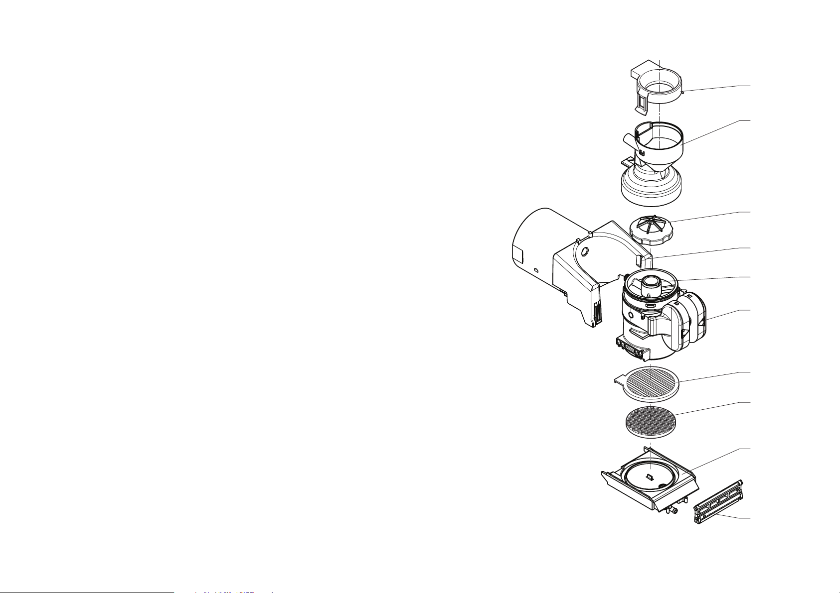
• Periodically, according to the operating
condition of the machine and in any case
at least weekly, it will be necessary to
clean all parts that come in contact with
the drink.
• Washing can be carried out in a
dishwasher (60°C max.) or using normal
dish detergent.
• The fresh-brewer consists in the following
parts, see illustration:
Deep cleaning
Note: Only clean the air cylinder, when
necessary!
Legend to illustration
1 - Mixing funnel hood
2 - Mixing funnel
3 - Upper valve
10.2011 FB 7100 PLUS 43
4 - Air cylinder
5 - Brewer cylinder
6 - Cylinder grip
7 - Filter
8 - Filter gasket
9 - Filter support spring
10 - Scraper
Page 48
Deep cleaning
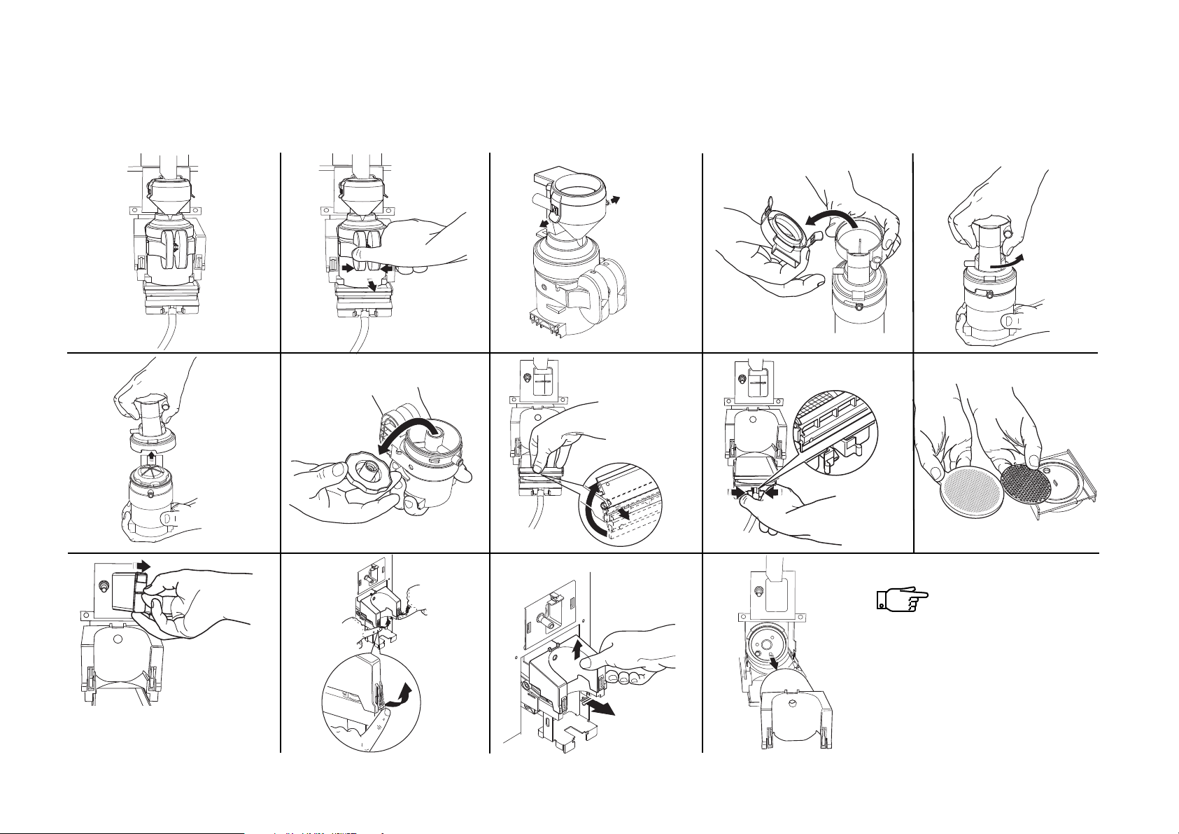
The illustrations to
be read row by row
1) from left to right,
and
2) from top to bottom.
1
23 4 5
6
78 9 10
11
12
13
14
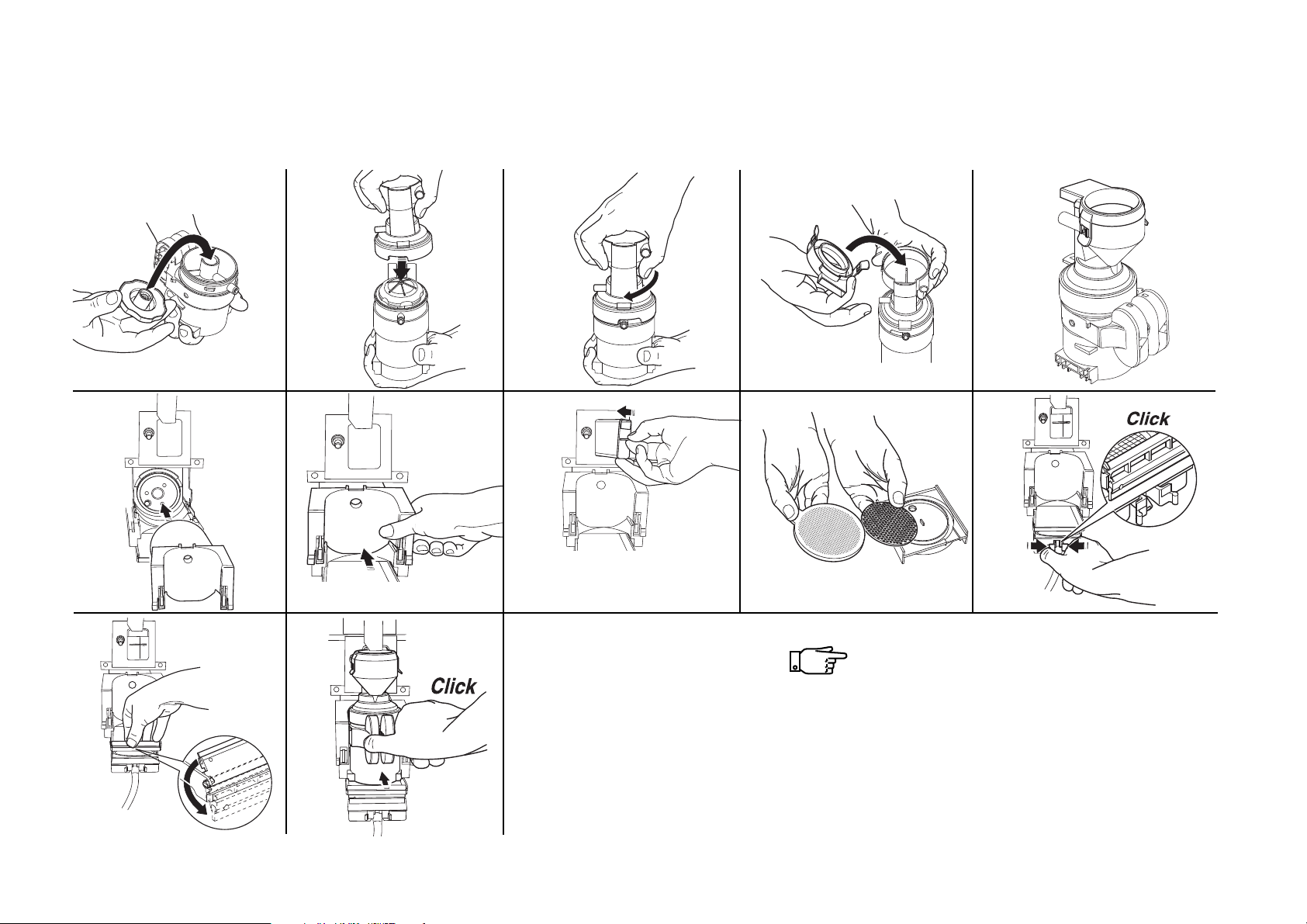
Disassembling the freshbrew unit
The parts to be cleaned are disassembled in the sequence indicated below:
44 FB 7100 PLUS 10.2011
Page 49
The illustrations to be read row by row
1) from left to right, and
2) from top to bottom.
1
23 4 5
6
7910
12
8
11
Reassembling the freshbrew unit
The parts of the freshbrew unit are reassembled in the sequence indicated below:
Deep cleaning
10.2011 FB 7100 PLUS 45
Page 50
Deep cleaning
40 41
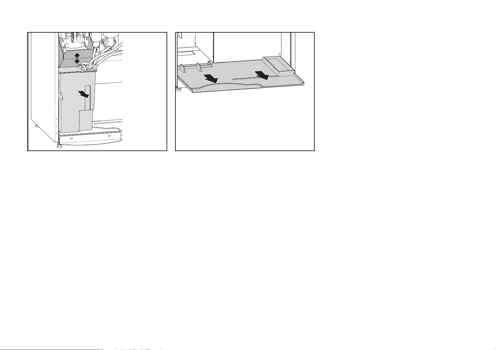
Emptying the solid waste container
• Take out the solid waste container, empty
it and insert a new liner (fig. 40).
46 FB 7100 PLUS 10.2011
Cleaning the base tray
• Remove and clean the base tray from
machine (fig. 41).
Page 51
Deep cleaning
42 43 44
Cleaning the cup carrier
• Remove the cup carrier (fig. 42) (see
regular cleaning).
• Clean the drip grid and tray (see regular
cleaning).
10.2011 FB 7100 PLUS 47
Cleaning the drip tray
• Take out and clean the drip tray and its
parts (fig. 43 and 44). (see regular
cleaning).
Always wipe sensor in lid dry
(fig.44).
Page 52
Deep cleaning
45 46
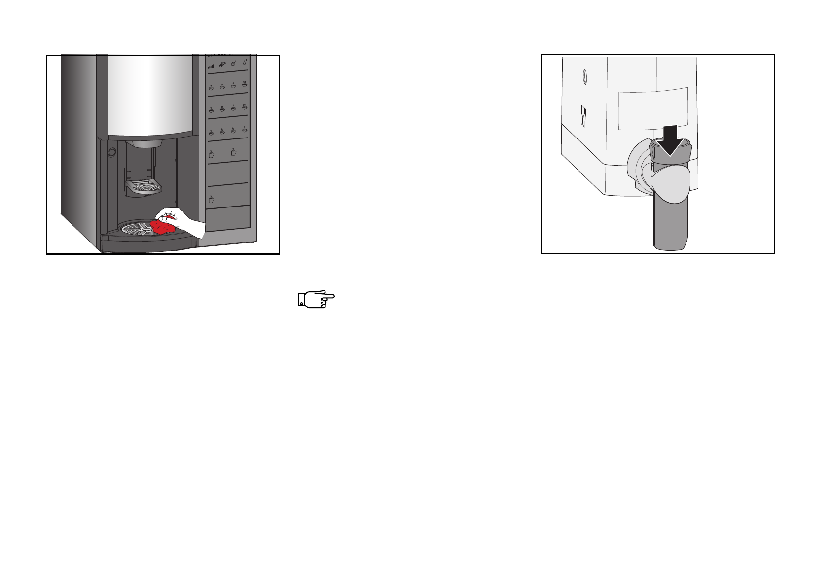
Cleaning inside and outside
• Clean the door and housing inside and
outside, and finally the bottom with a
clean, damp cloth (fig. 45).
• Flush all parts which have been soaking
thoroughly with clean and warm water.
• Dry all parts with a dry cloth.
48 FB 7100 PLUS 10.2011
Check that no dirt or cleaning
agent remains on the parts.
Mounting cleaned parts
• Remount all parts in reverse order.
• As to the freshbrew unit, see
“Reassembling the freshbrew unit” on
page 45
• Remount all canisters and push the outlet
tubes downwards to open the outlet
spouts of the canisters (fig. 46).
Page 53
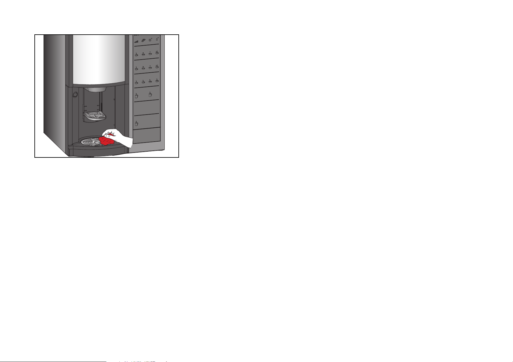
47
Rinsing and last check
• Turn on machine with the main switch.
Deep cleaning
• Rinse machine twice (see regular
cleaning).
• Clean outside of machine with a clean
damp cloth (fig. 46).
• Perform a test dispensing by pressing a
selection button e.g. coffee with milk and
sugar.
10.2011 FB 7100 PLUS 49
Page 54
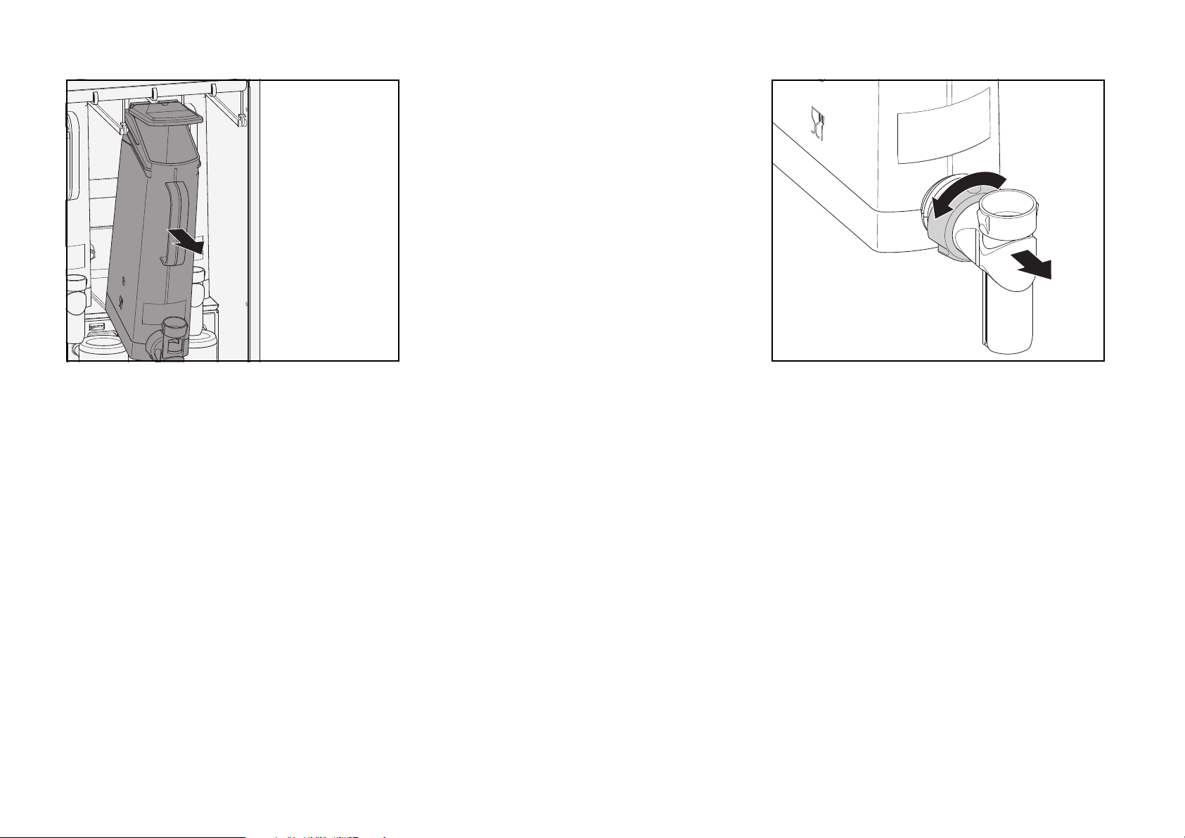
Occasional routines
48 49
Cleaning the instant ingredient canisters
• Push the outlet tube upwards to close the
outlet spout of the canister.
• Empty the ingredient of the canister into a
plastic bag or a clean container.
• Unscrew locking nut on front side of
canister and remove the outlet spout
(fig. 49).
• Take the canister by the handle and pull it
forwards (fig. 48) until end stops in
guiding rail. Lift the canister upwards and
pull forwards over the end stops. The lid is
automatically triggered open.
50 FB 7100 PLUS 10.2011
• Unscrew locking nut on back side of
canister and remove the dosing system.
Page 55
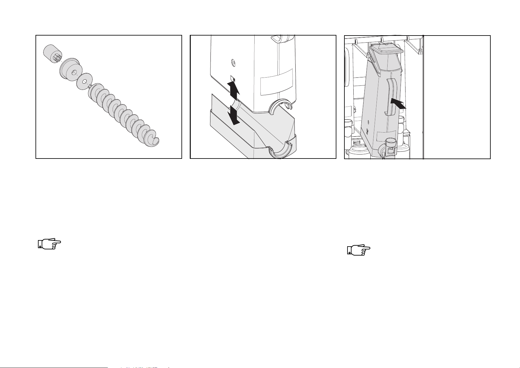
Occasional routines
50 51 52
• Separate dosing system (fig. 50):
- coupling
- sealing bushing
- auger
- felt disc
All parts of the instant ingredient
canisters are dishwasher-proof,
except the felt disc.
10.2011 FB 7100 PLUS 51
• Separate bottom part from canister part
(fig. 51).
• Soak all components in hot water with
cleaning agent, except felt disc.
• Rinse all items thoroughly in hot clean
water
• Let components dry completely
• Reassemble instant ingredient canister in
reverse order.
• Return canister to its former position
(fig. 52).
• Fill canister with instant ingredient.
• Repeat procedure for all canisters.
Ensure that the outlet tube points
the open end downwards.
The canisters must always be returned to their original position.
Page 56
Occasional routines
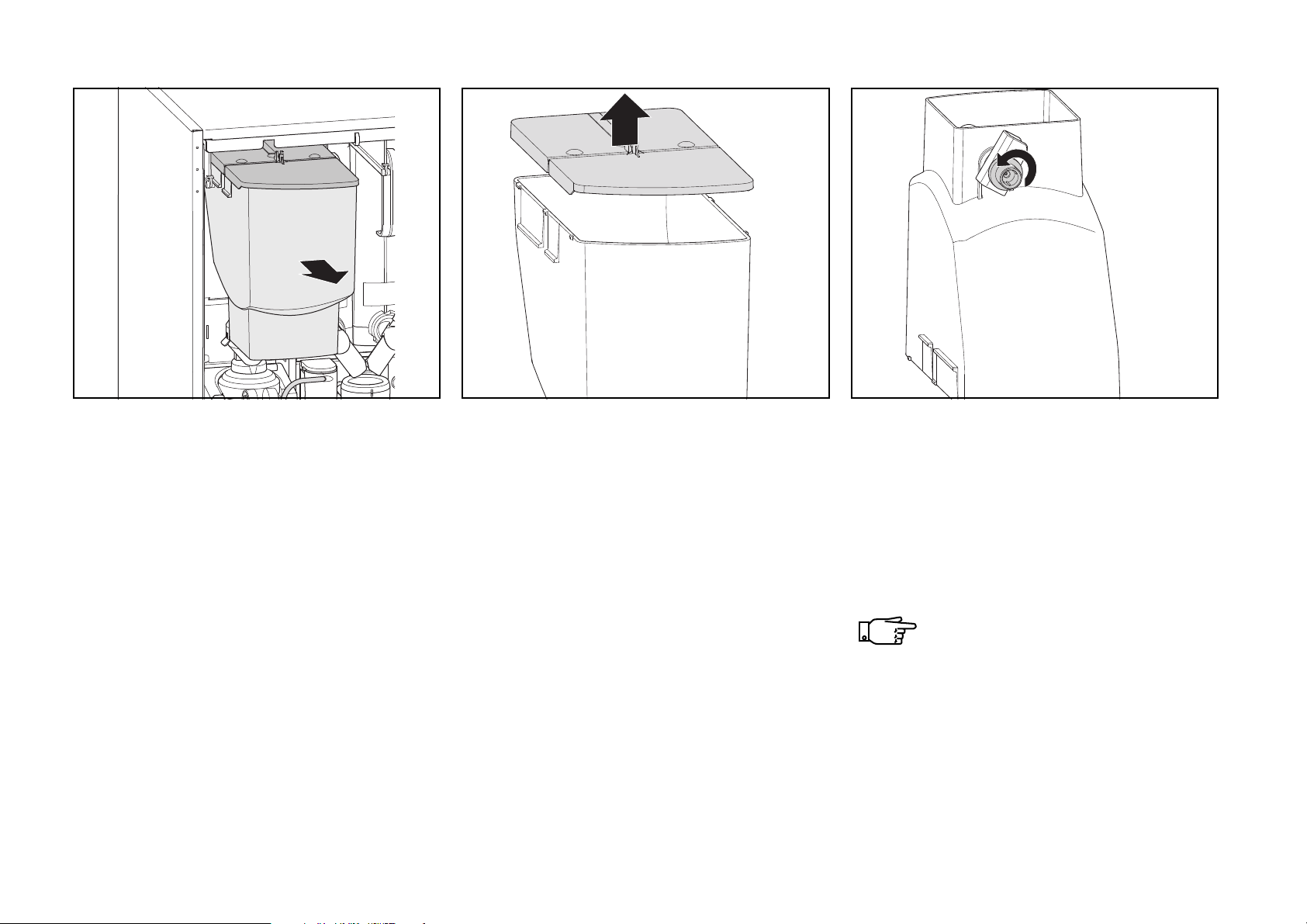
53 54 55
Cleaning the single chamber coffee canister
• Pull forwards and remove the freshbrew
ingredient canister from its suspensions
rails (fig. 53)
• Remove the lid and empty the canister
into a plastic bag or a clean container (fig.
54).
• Place the canister upside down on a
table.
• Loosen the remaining coffee by turning
the coupling (fig. 55) and by knocking on
the bottom of the dosing system.
• Wipe the inside of the canister with a soft,
clean and dry brush.
Take care not to damage the
mixing wire.
The canister and canister parts are
not dishwasher-proof.
52 FB 7100 PLUS 10.2011
Page 57
56
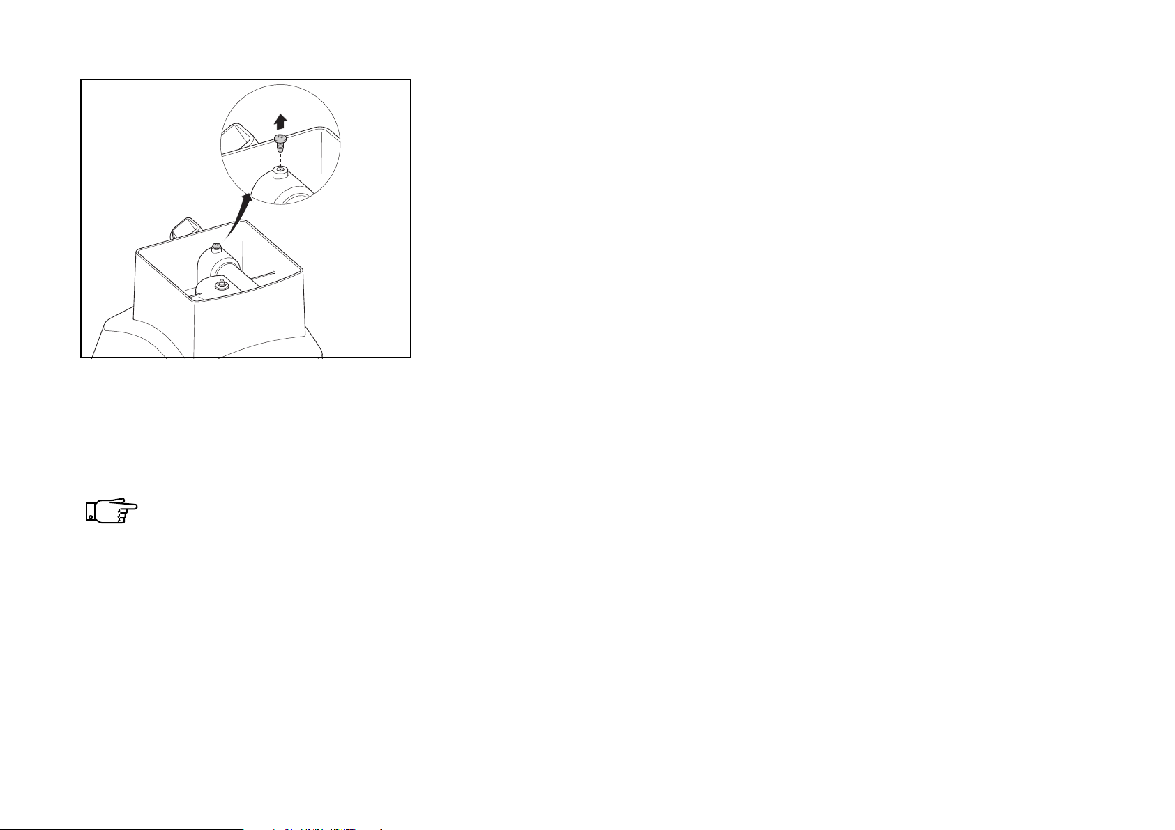
• For a heavily soiled canister loosen the
retaining screw of the auger (fig. 56) and
carefully remove the dosing system.
Take care not to damage the
mixing wire.
Do not use a brush.
• Dry the canister.
• Assemble canister and dosing system.
• Fill canister with freshbrew ingredient and
reinsert in machine.
Occasional routines
Cleaning the dual chamber coffee canister
A dual canister has two coffee chambers and
two dosing systems.
Each chamber and dosing system of the dual
chamber canister are disassembled and
cleaned in the same way as a canister with
one coffee chamber and one dosing system.
• Clean the canister in hot water.
10.2011 FB 7100 PLUS 53
Page 58

Occasional routines
Replacing brewer filter and gasket
• As well as cleaning every week and/or
every 1,000 selections, a nylon brewer
filter or the gasket for a metallic filter must
be replaced after a certain amount of
selections, even if apparently still efficient:
- Nylon filter for coffee: every 25.000
dispensings
- Gasket for metal filter: every 50.000
dispensings.
54 FB 7100 PLUS 10.2011
Be sure to use correct nylon filter
for tea / coffee brewing:
- nylon tea filter has a red seal.
- nylon coffee filter has a neutral
white seal.
Page 59
End
Rinse total machine
Rinse with stop
Rinse with stop
Rinsing-please wait!
Sel
*Open door
*Remove FB canister
*Add cleaning agent
*Close door
*Open door
*
Reposition FB canister
*Close door
*Empty pot
*Repeat if necessary
1
v
Wait until program
has finished
(1) (2) (3) (4)
-----SHORTCUTS-----
*
(1)=Rinse 3=Counter
(2)=Return 4=Menu
Start
*Close door
*Place pot
on pot platform
Sel
Add cleaning agent
and close door
FB 7100
PLUS
57
Occasional routines
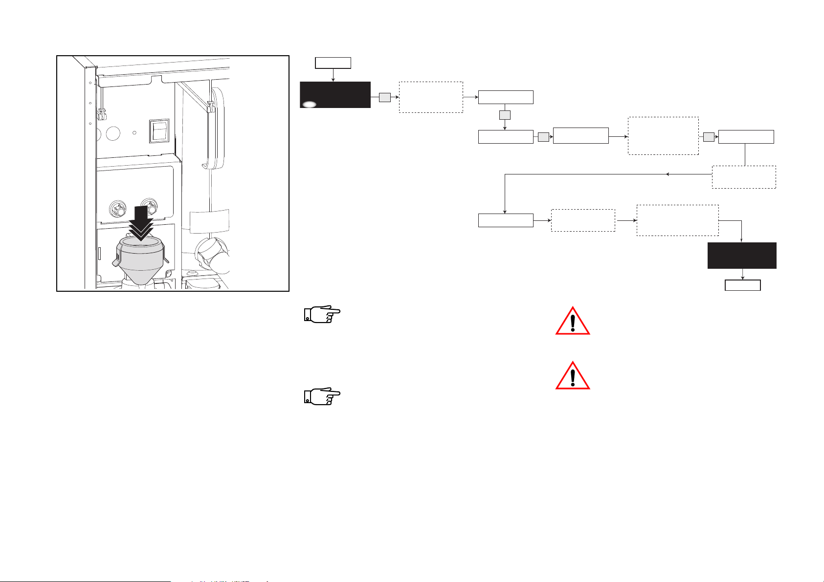
Rinsing / descaling the brewer
The brewer rinse procedure automatically
carries out four rinse cycles, one time with
cleaning agent and three times with clean
water (fig. 57).
• Have an empty pot (min. 1.5 l) and
• Open the door, remove the coffee canister,
10.2011 FB 7100 PLUS 55
cleaning or descaling agent ready.
turn to the display and follow the diagram
to perform a rinse of the brewer.
Do not stop the rinsing before the
full four cycles are completed as
otherwise residues of the cleaning
or descaling agent may remain in
the brewer and outlet hose.
Should the procedure be interrupted, e.g if the door is
accidentally opened too early, the
brewer must either be
disassembled and rinsed manually
or a new rinse procedure must be
performed.
There is a risk of scalding from hot
water.
Most descaling agents are caustic.
To protect your eyes and your skin
follow the manufacturer’s
instructions
Page 60
Additional routines
Continued on next page
FB 7100
PLUS
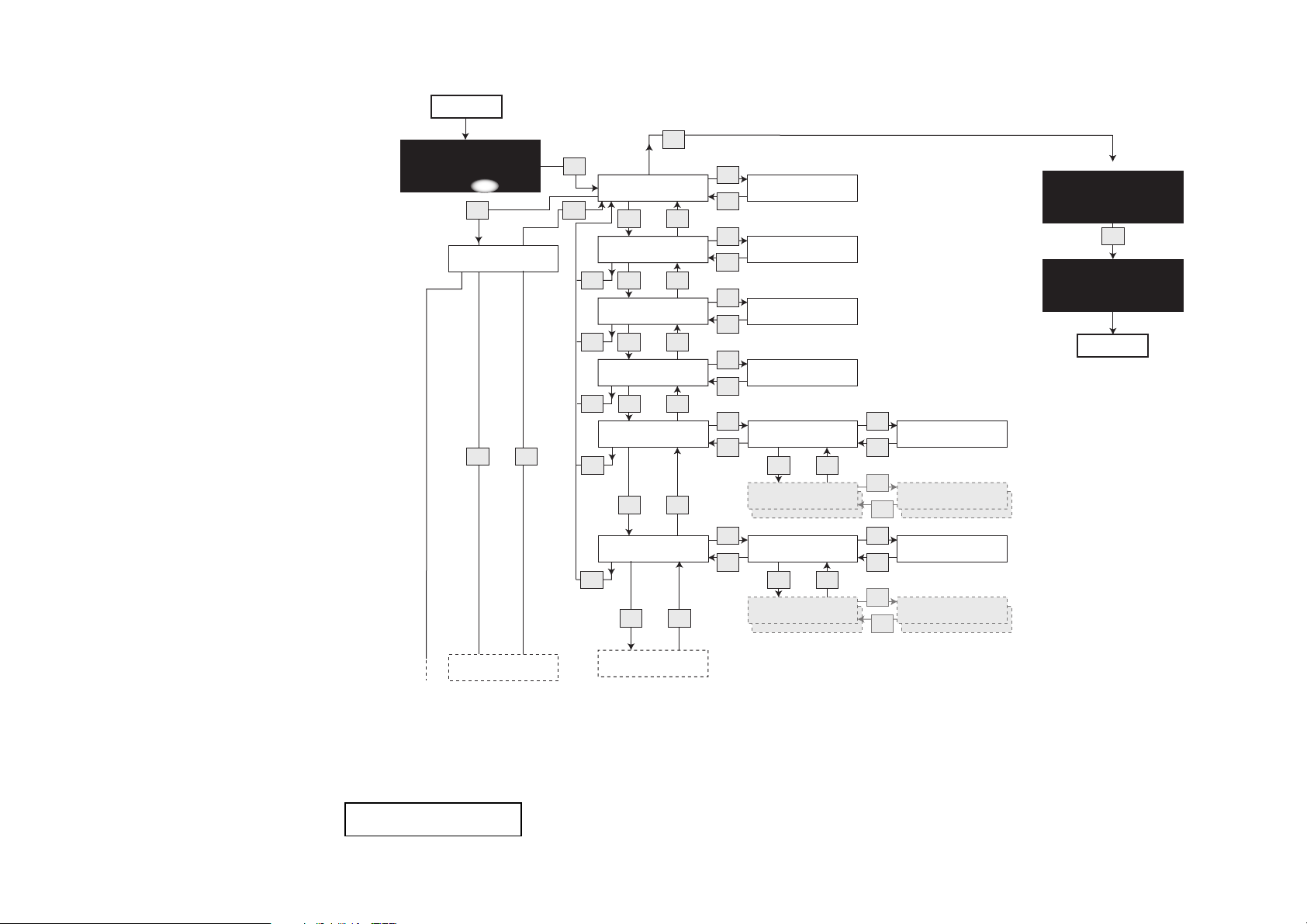
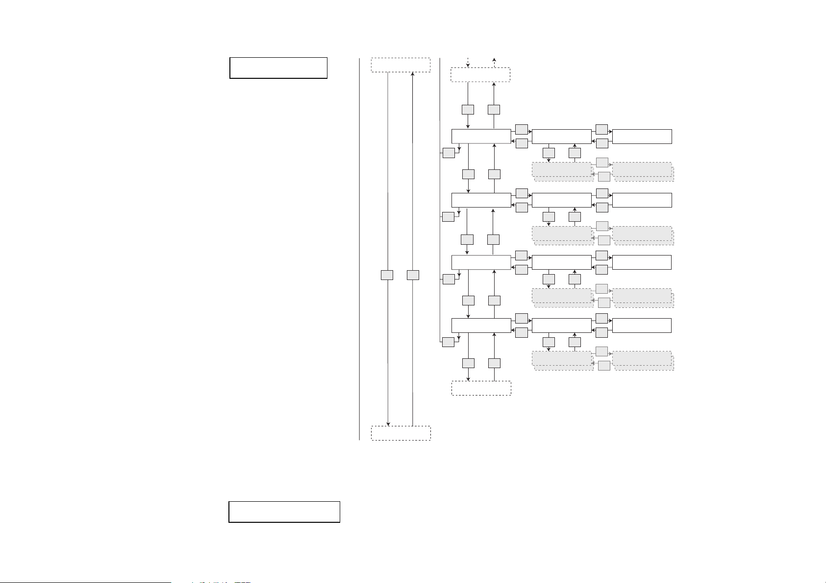
Calling and resetting counters
Follow this diagram to check
and reset counters.
Sales turnover and numbers
of items sold are available as
totals as well as by individual
types of drink selections.
------SHORTCUTS----*(1)=Rinse 3=Counter
(2)=Return 4=Menu
Start
(1) (2) (3) (4)
Esc
Sales Audit
v ^
3
Total number, nres
Sel
Total turnover, nres
Esc
Total number, res
Esc
Total turnover, res
Esc
No. per drink, nres
Esc
No. per drink, res
Esc
Esc
v
v
v
v
v ^
v ^
Sel
Total: xxxxxxx
OK
^
Sel
Total: 00000.00
OK
^
Sel
Total: xxxxxxx
OK
^
^
Sel
Total: 00000.00
OK
Sel
Coffee black
Esc
Coffee w sugar
Sel
Coffee black
Esc
Coffee w sugar
v ^
v
Sel
Total: xxxxxx
OK
Sel
Total: 000.00
OK
Sel
Total: xxxxxx
OK
^
Sel
Total: 000.00
OK
--MENU SELECTION--*Test
Operator
Esc
End
56 FB 7100 PLUS 10.2011
Cash audit
Turn. p. drink,nres
Page 61
Additional routines
Diagram continued
Continued on next page
Sales audit
v ^
No. per drink, res
v ^
Turn. p. drink,nres
Esc
v ^
Turn. p. drink,res
Esc
v ^
MB per drink, nres
Esc
v ^
MB per drink, res
Esc
v ^
Sel
Coffee black
Esc
Coffee w sugar
Sel
Coffee black
Esc
Coffee w sugar
Sel
Coffee black
Esc
Coffee w sugar
Sel
Coffee black
Esc
Coffee w sugar
v ^
v
v ^
v
Sel
Total: xxxxxx
OK
Sel
Total: 000.00
OK
Sel
Total: xxxxxx
OK
^
Sel
Total: 000.00
OK
Sel
Total: xxxxxx
OK
Sel
Total: 000.00
OK
Sel
Total: xxxxxx
OK
^
Sel
Total: 000.00
OK
10.2011 FB 7100 PLUS 57
No. per group, nres
Cash audit
Page 62
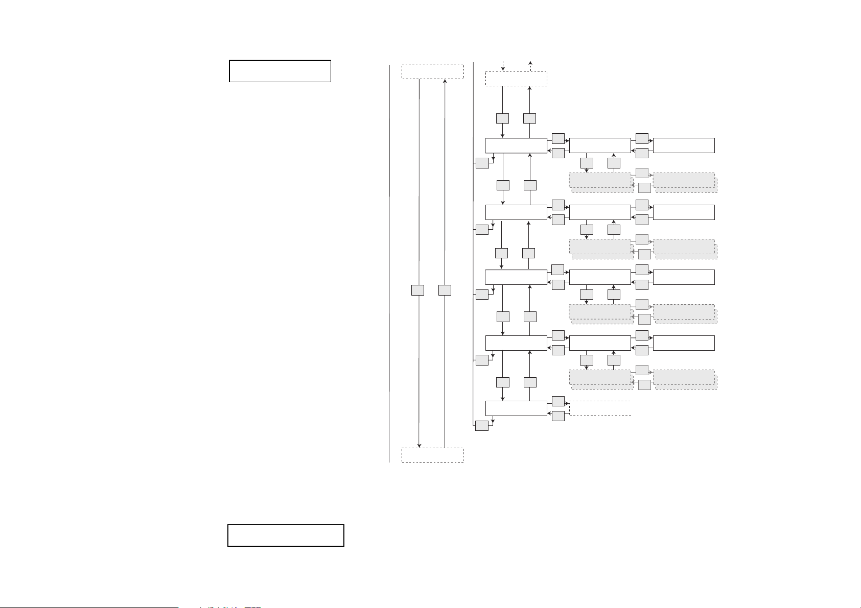
Additional routines
Diagram continued
Continued on next page
Sales audit
v ^
MB per drink, res
v ^
No. per group, nres
Esc
v ^
No. per group, res
Esc
v ^
Turn. p. group,nres
Esc
v ^
Turn. p. group,res
Esc
v ^
Card audit
Esc
Sel
Esc
Sel
Esc
Sel
Esc
Sel
Esc
Sel
Esc
Group 1
v ^
Group 2
Group 1
v
Group 2
Group 1
v ^
Group 2
Group 1
v
Group 2
Sel
Total: xxxxxx
OK
Sel
Total: 000.00
OK
Sel
Total: xxxxxx
OK
^
Sel
Total: 000.00
OK
Sel
Total: xxxxxx
OK
Sel
Total: 000.00
OK
Sel
Total: xxxxxx
OK
^
Sel
Total: 000.00
OK
58 FB 7100 PLUS 10.2011
Cash audit
Page 63
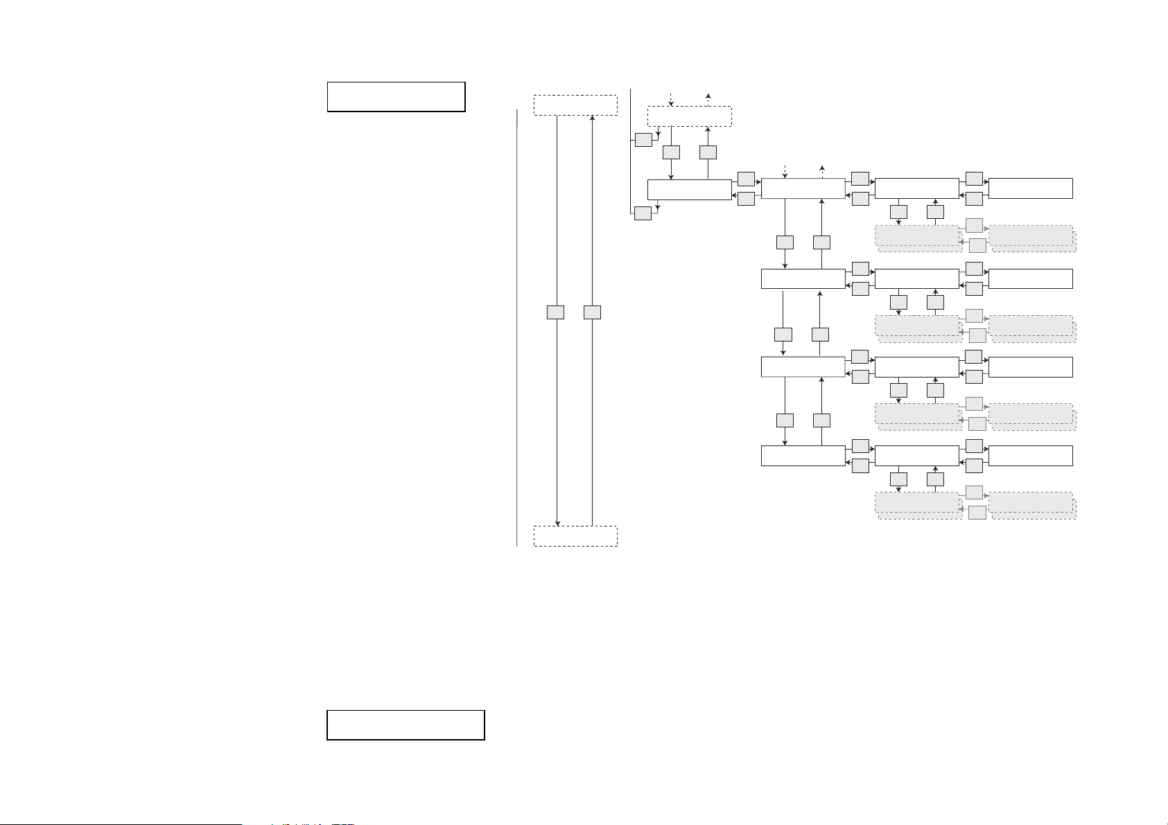
Additional routines
Diagram continued
Continued on next page
Sales audit
v ^
Turn. p. group,res
Esc
v ^
Card audit
Esc
Sel
No. per drink, nres
Esc
No. per drink, res
Turn. p. drink,nres
Turn. p. drink,res
v ^
v ^
v ^
Sel
Coffee
Esc
Coffee with milk
Sel
Coffee
Esc
Coffee with milk
Sel
Coffee
Esc
Coffee with milk
Sel
Coffee
Esc
Coffee with milk
v ^
v
v ^
v
Sel
Total: 0000000
OK
Sel
Total: 0000000
OK
Sel
Total: 0000000
OK
^
Sel
Total: 0000000
OK
Sel
Total: 0000000.00
OK
Sel
Total: 0000000.00
OK
Sel
Total: 0000000.00
OK
^
Sel
Total: 000.00
OK
10.2011 FB 7100 PLUS 59
Cash audit
Page 64
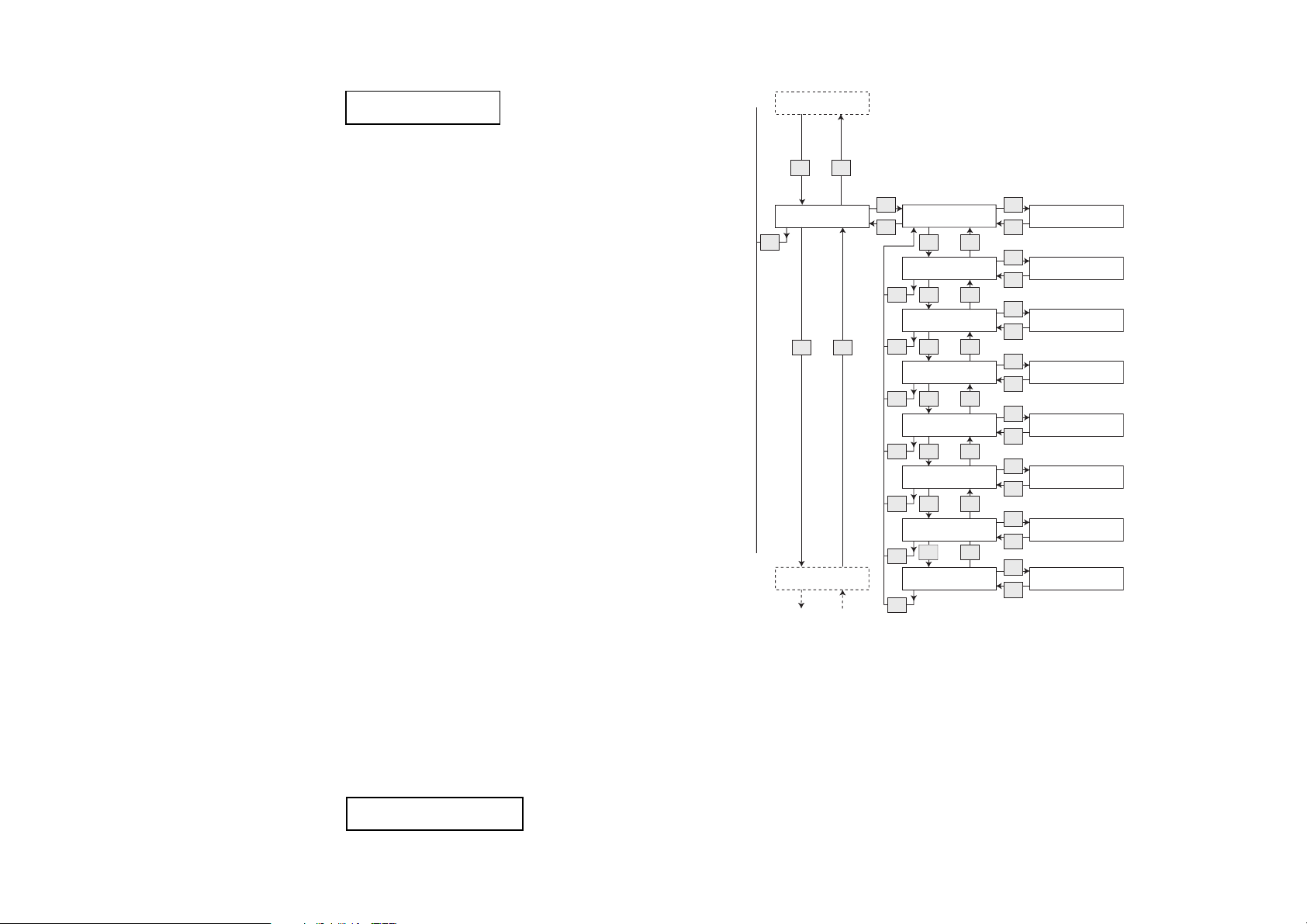
Additional routines
Cashless audit
Cash audit Amount: 00000.00
Sel
OK
Amount: 00000.00
Sel
OK
Amount: 00000.00
Sel
OK
Amount: 00000.00
Sel
OK
Money to tubes
Sel
Esc
Money to cash box
v ^
Collected money
v
^
Manually filled
*
v
^
v ^
Esc
Esc
Esc
Esc
Amount: 00000.00
Sel
OK
Manually delivered
v
^
Esc
Amount: 00000.00
Sel
OK
Value overpay
v
^
Esc
Amount: 00000.00
Sel
OK
Dispensed change
Esc
v
^
v ^
Sales audit
Number: 0000000
Sel
OK
Number of tokens
v
^
Esc
Diagram continued
Continued on next page
* Applicable only to BDV and MDB/
ICP coin mechanisms.
60 FB 7100 PLUS 10.2011
Page 65
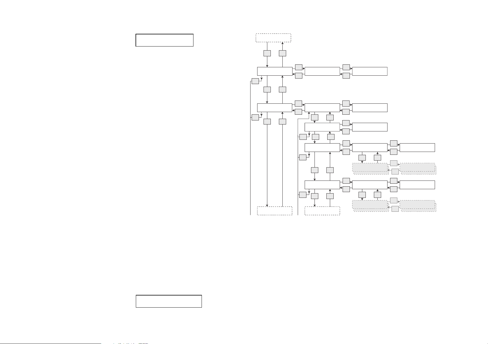
Number: xxxxx
Sel
OK
Number: xxxxx
Sel
OK
Revalued amount
Sel
Esc
Amount: 00000.00
Sel
Esc
Cashless audit
Esc
v ^
v ^
Total no. ,nres
Sel
Esc
Total no. ,res
v ^
Esc
Freevend audit
Esc
v
^
Cash audit
v ^
v ^
Coffee w sugar
Total: 000.00
Sel
OK
Coffee black
Sel
Esc
Total: xxxxxx
Sel
OK
v
^
Coffee w sugar
Total: 000.00
Sel
OK
Esc
No. per drink, res
Coffee black
Sel
Esc
Total: xxxxxx
Sel
OK
Esc
No. per drink, nres
v ^
MB. discount audit
v ^
No. per group, res
Diagram continued
Continued on next page
Additional routines
10.2011 FB 7100 PLUS 61
Page 66

Additional routines
Diagram continued
Continued on next page
Free vend audit
v ^
MB. discount audit
Esc
v ^
Discount key audit
Esc
v ^
No. per group, nres
Esc
v ^
No. per group, res
Esc
Sel
MB. number, nres
Esc
Sel
Esc
v ^
MB. turnover, nres
v
Esc
MB. number, res
v ^Esc
MB. turnover, res
Esc
D.Key number, nres
v ^
D.Key turnover, nres
v
Esc
D.Key number res
v ^Esc
D.Key turnover, res
Esc
Sel
Group 1
Esc
Sel
Esc
Sel
OK
Sel
OK
^
Sel
OK
Sel
OK
Sel
OK
Sel
OK
^
Sel
OK
Sel
OK
v ^
Group 2
Group 1
v
Group 2
Number: xxxxx
Amount: 00000.00
Number: xxxxx
Amount: 00000.00
Number: xxxxx
Amount: 00000.00
Number: xxxxx
Amount: 00000.00
Sel
Total: xxxxxx
OK
Sel
Total: 000.00
OK
Sel
Total: xxxxxx
OK
^
Sel
Total: 000.00
OK
62 FB 7100 PLUS 10.2011
Time Discount audit
Page 67
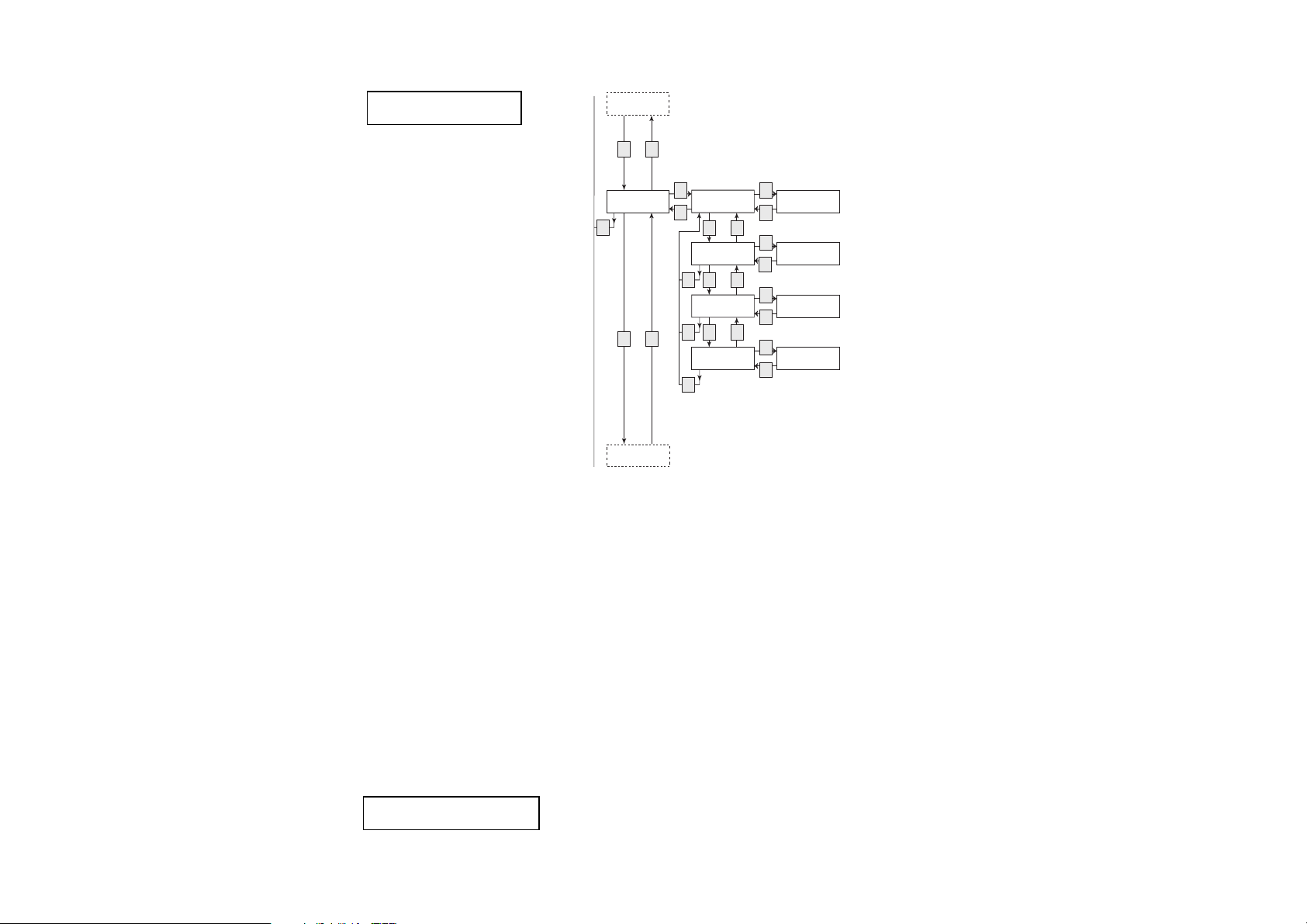
Discount key audit
Diagram continued
Continued on next page
v ^
Additional routines
Time Discount audit
Esc
v ^
Step price audit
Sel
T.Disc number ,nres
Esc
v
T.Disc turnov., nres
Esc
v
T.Disc number ,res
Esc
v
T.Disc turnov., res
Esc
^
^
^
Sel
Number xxxxxxx
OK
Sel
Number xxxxxxx
OK
Sel
Number xxxxxxx
OK
Sel
Number xxxxxxx
OK
10.2011 FB 7100 PLUS 63
Page 68
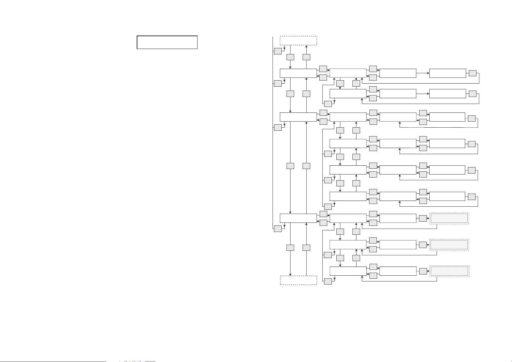
Additional routines
Diagram continued
Time Discount Audit
Esc
v ^
Step price audit
Sel
Sp. turnover, nres
Esc
Esc
v ^
Sp. turnover, res
Esc
Test audit Test no. , nres
Sel
Esc
Esc
Test no. , res
Esc
v ^
No. per group, nres
Esc
No. per group, res
Esc
Sel
Reset counters
Reset sales audit
Esc
Esc
v ^
Reset cash audit Continue ?
Esc
Reset test audit Continue ?
Printing
Esc
v ^
v ^
v ^
v ^
v ^
v ^
Sel
Step price, nres (+)
Amount: 000.00
Esc
Sel
Step price, res(+)
Amount: 000.00
Esc
Sel
AUDIT PER DRINK
[Drink]
Esc
Sel
AUDIT PER DRINK
[Drink]
Esc
Sel
AUDIT PER GROUP
[Group]
Esc
Sel
AUDIT PER GROUP
[Group]
Esc
Sel
Continue ?
Esc
Sel
Esc
Sel
Esc
Step price, nres (-)
Amount: 000.00
Step price, res(-)
Amount: 000.00
Sel
Number sold of [drink]
Total: 0000000
Esc
Sel
Number sold of [drink]
Total: 0000000
Esc
Sel
Number sold of [group]
Total: 0000000
Esc
Sel
Number sold of [group]
Total: 0000000
Esc
Reset of sales
OK
audit finished
Reset of cash
OK
audit finished
Reset of test
OK
audit finished
OK
OK
OK
OK
OK
OK
64 FB 7100 PLUS 10.2011
Page 69
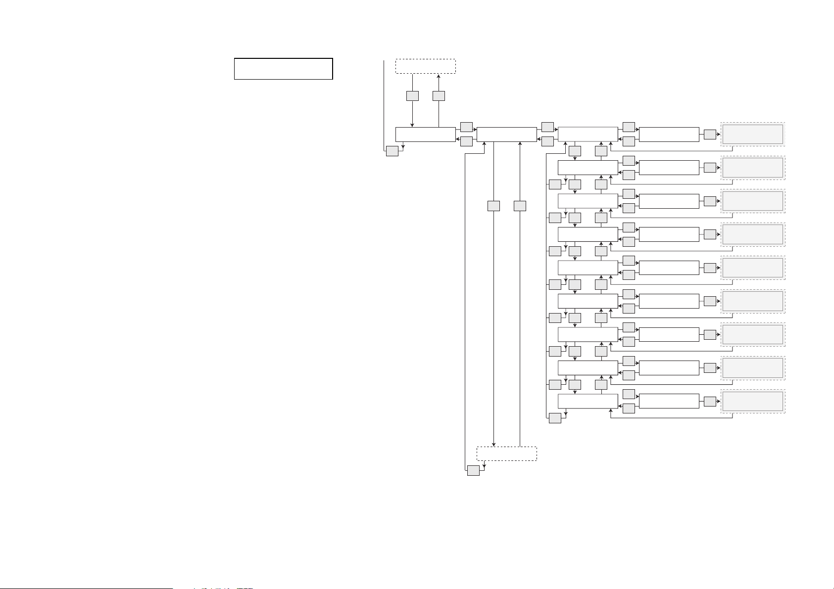
Reset counters
Diagram continued
v ^
Additional routines
Esc
Printing
Sel
Esc
Not resettable
v ^
Sel
Overall
Esc
v ^
Selections Counters
v
Esc
Time Bands
v ^Esc
Free Vend
v ^
Esc
Discounts
Esc
v ^
Errors
Esc
v ^
Cash Audit
Esc
v ^
Test Audit
Esc
v
Group Counters
Esc
Sel
Printing audit
?
Continue
OK
Sel
Printing audit
Continue
?
Continue
Continue
Continue
Continue
Continue
Continue
Continue
?
?
?
?
?
?
?
OK
^
Sel
Printing audit
OK
Sel
Printing audit
OK
Sel
Printing audit
OK
Sel
Printing audit
OK
Sel
Printing audit
OK
Sel
Printing audit
OK
^
Sel
Printing audit
OK
OK
OK
OK
OK
OK
OK
OK
OK
OK
Please wait
Printing
in progress
Please wait
Printing
in progress
Please wait
Printing
in progress
Please wait
Printing
in progress
Please wait
Printing
in progress
Please wait
Printing
in progress
Please wait
Printing
in progress
Please wait
Printing
in progress
Please wait
Printing
in progress
Resettable
Esc
10.2011 FB 7100 PLUS 65
Page 70
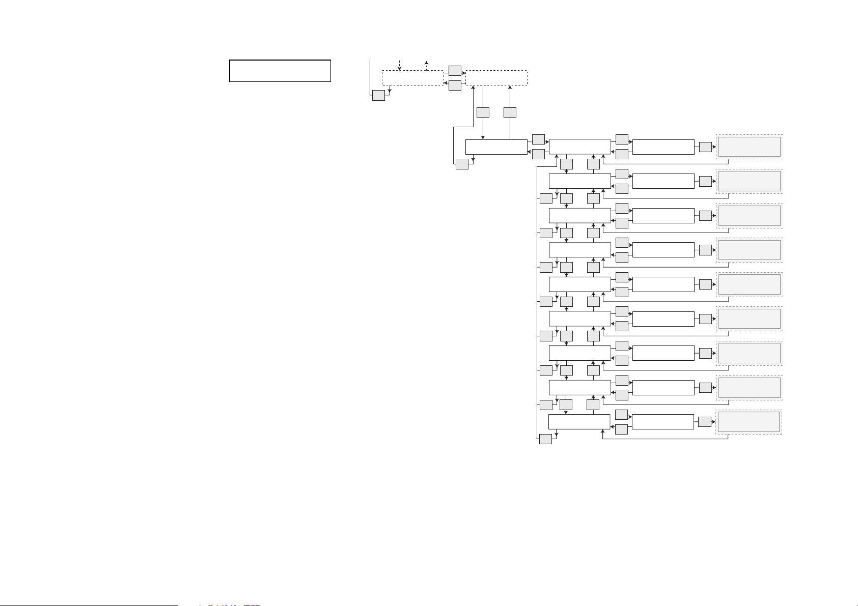
Additional routines
Diagram continued
Printing Not resettable
Esc
Sel
Esc
v ^
Resettable
Esc
Sel
Overall
Esc
v ^
Selections Counters
v
Esc
Time Bands
v ^Esc
Free Vend
Esc
v ^
Discounts
Esc
v ^
Errors
v ^
Esc
Cash Audit
Esc
v^
Test Audit
Esc
v
Group Counters
Esc
Sel
Printing audit
Continue
?
Continue
Continue
Continue
Continue
Continue
Continue
Continue
?
?
?
?
?
?
?
?
OK
Sel
Printing audit
OK
^
Sel
Printing audit
OK
Sel
Printing audit
OK
Sel
Printing audit
OK
Sel
Printing audit
OK
Sel
Printing audit
OK
Sel
Printing audit
OK
^
Sel
Printing audit
Continue
OK
OK
OK
OK
OK
OK
OK
OK
OK
OK
Please wait
Printing
in progress
Please wait
Printing
in progress
Please wait
Printing
in progress
Please wait
Printing
in progress
Please wait
Printing
in progress
Please wait
Printing
in progress
Please wait
Printing
in progress
Please wait
Printing
in progress
Please wait
Printing
in progress
66 FB 7100 PLUS 10.2011
Page 71
Filling / Clean
Counters
Cash action
--MENU SELECTION--*Test
Operator
^ v Sel ESC
End
Sel
Esc
Cash collected
Sel
Esc
OK
Esc
v
^
Press < OK> if
cash was collected
Cash audit is
now adjusted
Esc
Esc
Esc
Select “Menu” -> “Enter Password” -> “Test” -> “Operator” -> “Filling/Clean”
Esc
FB 7100
58
Additional routines
Emptying the cash box
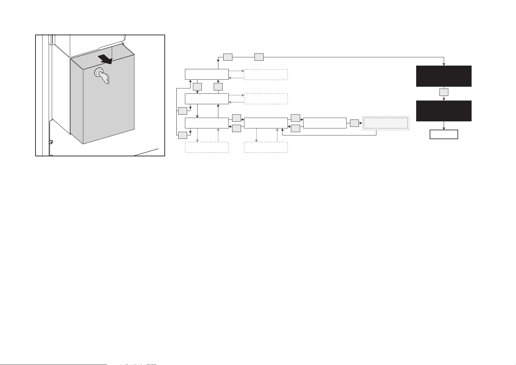
• Open the door of the vending
machine.
• Insert cash box key into keyhole and
turn it clockwise.
• Pull out the cash box and empty it.
(fig. 58)
• Turn to the display and follow the
diagram to register the removed
amount electronically.
The amount is registered under
“Collected money” (See “Calling and
resetting counters” on page 56).
10.2011 FB 7100 PLUS 67
Page 72
Additional routines
FB 7100
* Applicable only to BDV and MDB/
ICP coin mechanisms.
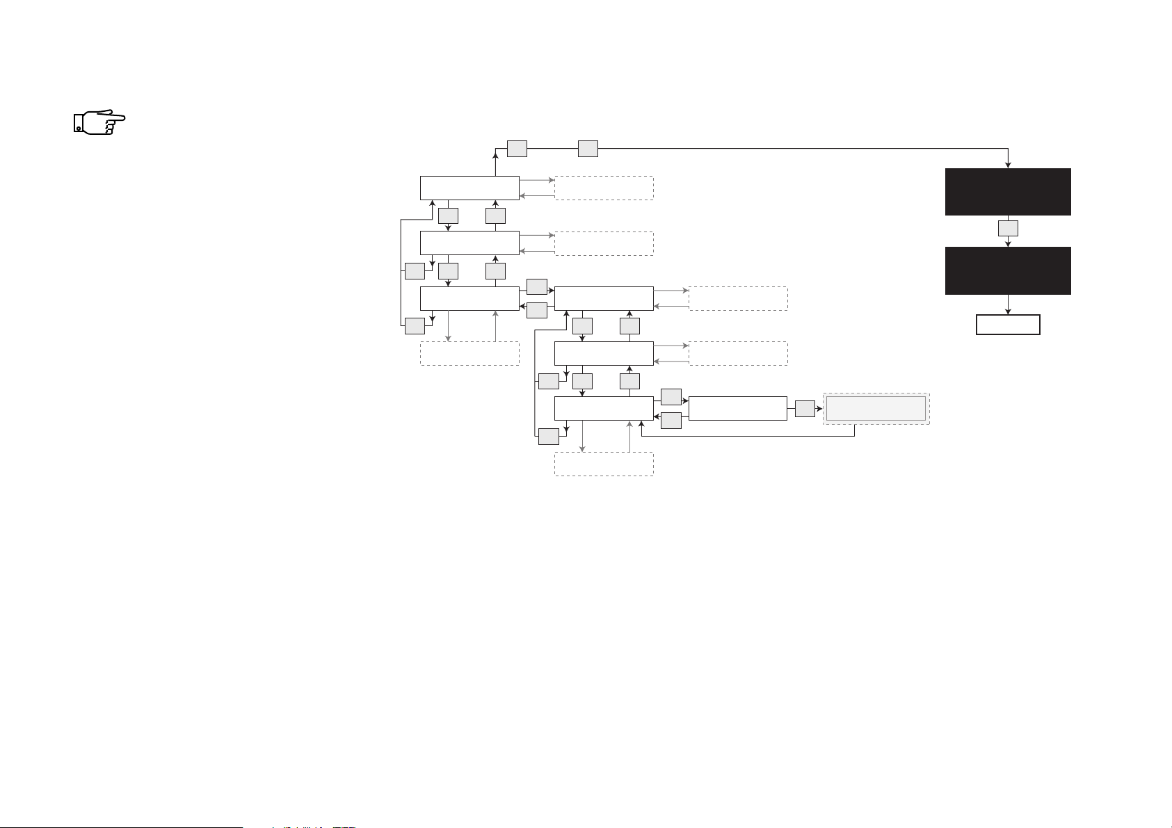
Adding change manually
This procedure is applicable
only to BDV and MDB/ICP
coin mechanisms.
Insert the change amount into the
machine through the coin slot.
Follow the diagram to electronically
register the inserted amount as
change.
The inserted amount is registered
under “Manually filled” (See “Calling
and resetting counters” on page 56)
Select “Menu” -> “Enter Password” -> “Test” -> “Operator” -> “Filling/Clean”
Filling / Clean
v
Counters
v ^
Esc
Cash action
Esc
Esc
^
Sel
Esc
Esc
Cash collected
v
Dispense coins
v
Esc
Manual filling
Esc
^
^
*
Sel
Esc
Press < OK> to
adjust audit
OK
Cash audit is
now adjusted
--MENU SELECTION--*Test
Operator
^ v Sel ESC
Esc
End
68 FB 7100 PLUS 10.2011
Page 73
Additional routines
FB 7100
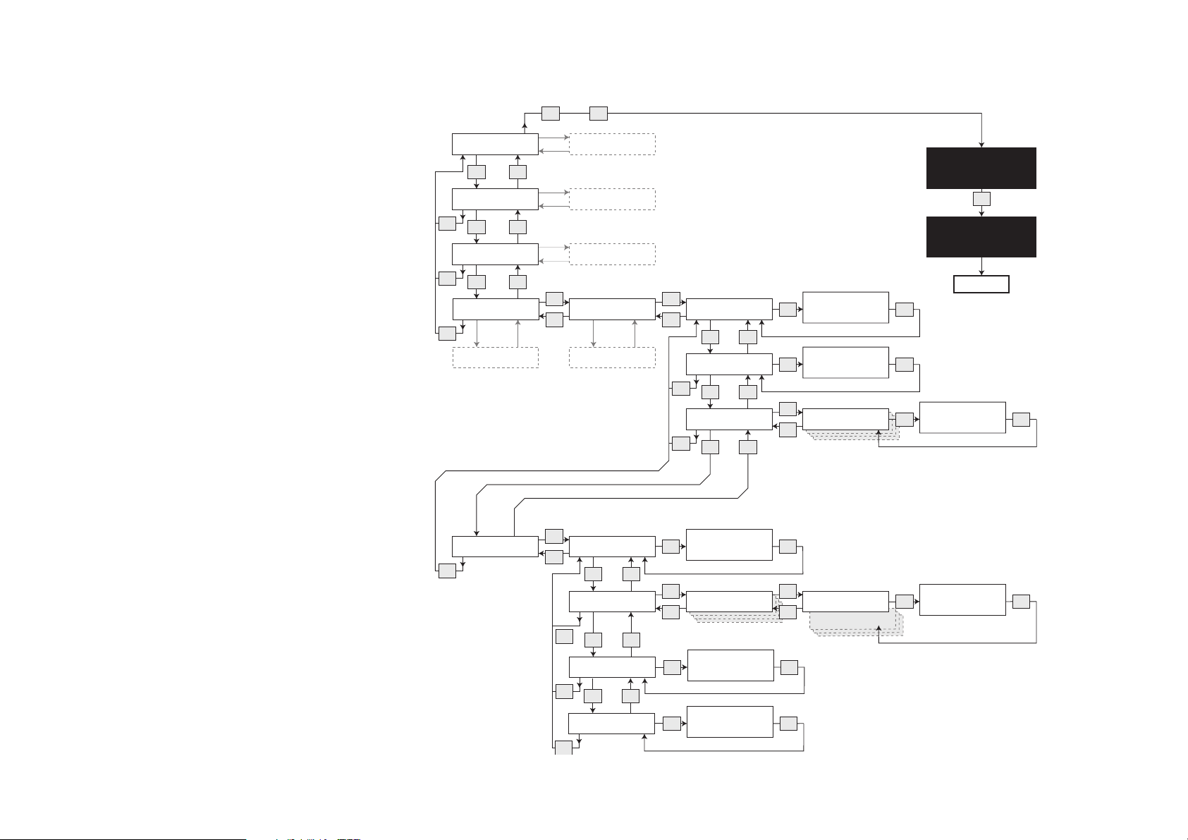
Changing prices
Follow this diagram to change the price
of a drink.
See the section Settings buttons on
page 10 for an explanation of how to
use the Plus (+), Minus (-), Next (->) and
Save (OK) buttons.
Select “Menu” -> “Enter Password” -> “Test” -> “Operator” -> “Filling/Clean”
Esc
Change prices
Sel
Global price
Esc
Price per cup
Esc
Price per drink
Esc
Sel
v ^
Sel
v ^
Sel
Esc
v ^
Filling/Clean
v ^
Counters
Esc
v ^
Cash action
Esc
v ^
Basic operations
Esc
Esc
Sel
Esc
Price per cup
Set value: 0000.00
(+) -> Esc OK
Price per cup
Set value: 0000.00
(-) (+) -> OK
Select drink
--MENU SELECTION--*Test
Operator
^ v Sel ESC
OK
OK
Price: Coffee black
Sel
Value: 0000.00
(-) (+) -> OK
Esc
End
OK
Step prices
Esc
Sel
Price On/Off
Esc
v ^
Set step price(s)
Esc
v ^
Global stepprice(+)
Esc
v ^
Global stepprice(-)
Esc
Step price(s)
Sel OK
(Off = 0, On = 1) : 0
(-) (+) Esc OK
Sel
Select drink
Esc
Global price (+)
Sel OK
Set value : 00.00
(-) (+) -> OK
Global price (-)
Sel OK
Set value : 00.00
(-) (+) -> OK
Sel
Esc
Preselection 1(+)
Preselection 1(-)
Set step price
Sel OK
Value : 00.00
(-) (+) -> OK
10.2011 FB 7100 PLUS 69
Page 74
Additional routines
--MENU SELECTION--*Operator
Technician
^ v Sel ESC
End
Machine settings
Basic operations
Esc
Esc
Set freevend, global
Service information
v
^
v ^
Cash action
v
^
Counter
v
^
Filling / Clean
v
^
Esc
Esc
Esc
Esc
Sel
Esc
(Off = 0, On = 1):1
Sel
Esc
Set percentage: 000
Sel
Esc
Key discount
v
^
Esc
Esc
Esc
OK
OK
v
^
Select “Menu” -> “Enter Password” -> “Test” -> “Operator” -> “Filling/Clean”
FB 7100
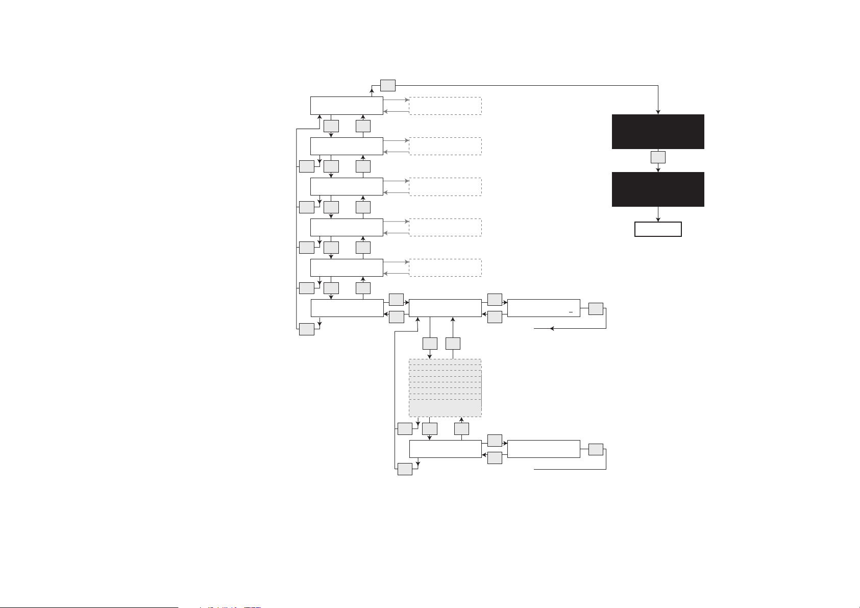
Setting of free vend and key discount
Follow this diagram to
• turn free vend on or off
or
• set or change key discount rates
70 FB 7100 PLUS 10.2011
Page 75

Time Discount
The Time discount option is used to set time periods during which
drinks are to be sold at a discount.
A percentage rate is given as a discount on all drinks during the set
periods.
Seven different discount periods can be programmed on a weekly
basis.
For each period a start day and time, and an end day and time must
be defined.
The start and end days are identified by progressive numbers:
(Monday=0, Tuesday=1, etc.) and all weekdays (ALL=7).
This means:
Additional routines
• A time discount period that crosses midnight requires two period
settings, see Example 1, periods 1 and 2.
• If a time discount is to apply within the same period of time every
day of the week, e.g. from 10 a.m. to 2 p.m. (10:00 to 14:00), one
period setting stating ALL as start and end day is sufficient. If a
time discount should apply only some of the days of a week, e.g.
Saturdays and Sundays, separate periods must be defined for
each of these days, see Example 2 next page.
• A period cannot have a ‘start time’ later than the ‘end time’, see
Non Example next page.
• The same time period cannot include days from different weeks,
i.e. a period cannot be set from Monday to Monday.
10.2011 FB 7100 PLUS 71
Page 76
Additional routines
Example 1:
• A time discount is to apply Monday to Friday from 10:00 p.m. to
06:00 a.m. Furthermore, time discount is to apply all day during
week-ends. Three period settings are required to define this
combination of time discounts:
Period 1
Set start day ALL=7 Set start time 22:00
Set end day ALL=7 Set end time 23:59
Result: Time discount is given between 10:00 p.m. and midnight of the same
day.
Period 2
Set start day ALL=7 Set start time 00:00
Set end day ALL=7 Set end time 06:00
Result:Time discount is given between midnight and 06:00 a.m. of the same
day.
Period 3
Set start day Sa=5 Set start time 06:00
Set end day Su=6 Set end time 23:59
Result: Time discount is given continuously all through the week-end.
Example 2:
Non example:
Period 1
Set start day All=7 Set start time 22:00
Set end day All=7 Set end time 06:00
Result: No time discount will be given as the end time cannot be earlier than the
start time for the same ‘day’ or ‘ALL’. In this case a time discount up till midnight
and another one from midnight and onwards should have been defined. (See
Example 1, Periods 1 and 2)
• A time discount is to apply Saturdays and Sundays between
10:00 a.m. and 2:00 p.m. Separate periods must be defined for
each of the two days:
Period 1
Set start day Sa=5 Set start time 10:00
Set end day Sa=5 Set end time 14:00
Period 2
Set start day Su=6 Set start time 10:00
Set end day Su=6 Set end time 14:00
Result: Time discount is given on Saturdays and Sundays between 10:00 a.m.
and 2:00 p.m.
72 FB 7100 PLUS 10.2011
Page 77
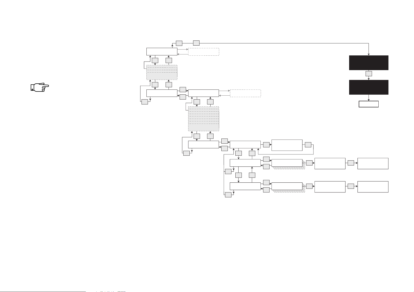
Additonal routines
FB 7100
Setting time discount
• Follow this diagram to set the
discount percentage rate and to
define one or more time periods (up
to seven periods) in which it is to
apply.
If the discount key is used
during an active Time
discount period, the higher of
the two discount rates will
apply.
Select “Menu” -> “Enter Password” -> “Test” -> “Operator” -> “Filling/Clean”
Esc
Sel
Set freevend, global
Esc
v
v
Time discount
Esc
^
^
Sel
Set Time discount
Esc
Set day(s)
Esc
Set time
Esc
v ^
v ^
Sel
Sel
Esc
Sel
Esc
Filling / Clean
v
v
Machine settings
Esc
Esc
^
^
Set Time discount
(0-100) :20
(-) (+) -> OK
Period 1
Period 1
OK
Set start day:
Sel
(Mo=0, Su=6, All=7):7
(-) (+) Esc OK
Set start time:
Sel
Time: 22:00
(-) (+) -> OK
--MENU SELECTION--*Test
Operator
^ v Sel ESC
Esc
End
Set end day:
OK
(Mo=0, Su=6, All=7):7
(-) (+) Esc OK
Set end time:
OK
Time: 23:59
(-) (+) Esc OK
10.2011 FB 7100 PLUS 73
Page 78
Additional routines
Example
The vending machine is to run Monday to Friday from 07:00 till
22:00. The remaining time of the week and during the weekend the
machine is set to energy saving. Three periods have to be set as
follows:
Non Example 1:
Non Example 2:
Period 1
Set start day ALL=7 Set start time 22:00
Set end day ALL=7 set end time 23:59
Result: The machine is ‘shut down’ every day from 22:00 till midnight the same
day.
Period 2
Set start day ALL=7 Set start time 00:00
Set end day ALL=7 set end time 07:00
Result: The machine is ‘shut down’ from midnight 00:00 till 07:00 in the morning
the same day.
Period 3
Set start day Fr=4 Set start time 22:00
Set end day Su=6 set end time 23:59
Result: The machine is shut down from Friday evening at 22:00 till Sunday
evening at 23:59.
Period 1
Set start day Mo=0 Set start time 22:00
Set end day Fr=4 set end time 07:00
Result: The machine is ‘shut down’ Monday at 22:00 till Friday at 07:00 which
was not the intention.
Period 1
Set start day All=7 Set start time 22:00
Set end day All=7 set end time 07:00
Result: The machine is not ‘shut down’ as the end time must not be earlier than
the start time for the same day or the setting ‘ALL’.
Energy saving periods
In order to save electric power when the machine is not in use, this
function is used to lower the water temperature in the boiler and to
switch off the door light.
The energy saving function is enabled / disabled in ‘Set state’.
7 energy saving periods can be programmed on a weekly basis.
For each period a start day and time, and an end day and time must
be defined. The start and end days are identified by progressive
numbers: (Monday=0, Tuesday=1, etc.) and all weekdays (ALL=7).
This means:
• An energy saving period that crosses midnight requires two
period settings, see Example, periods 1 and 2.
• If the periods are set overlapping, the machine will be shut
down as long as it is covered by one of these periods, see.
Example: Period 3.
• The same time period cannot include days from different weeks,
i.e. a period cannot be set from Monday to Monday.
• A period cannot have a ‘start time’ later than the ‘end time’, see
Non Example 2.
• Non Examples 1 and 2 illustrate settings which will give
unintended results.
The temperature during the energy saving period is set in ‘set
temperature’
74 FB 7100 PLUS 10.2011
Page 79

Switching off the door light during the energy saving mode is enabled
/ disabled in ‘set doorlight’.
If a selection button is activated during an energy saving
period, the machine leaves the energy saving mode and
returns to the vend mode. As soon as the temperature in
the water tank has reached the ‘nominal temperature’, the
machine is ready for dispensing, and the wanted drink can
be selected.
When the selection buttons have been left untouched for
more than 10 minutes after the last drinks dispensing, and
an energy saving period is still in force, the machine returns
to the energy saving mode.
Additional routines
10.2011 FB 7100 PLUS 75
Page 80
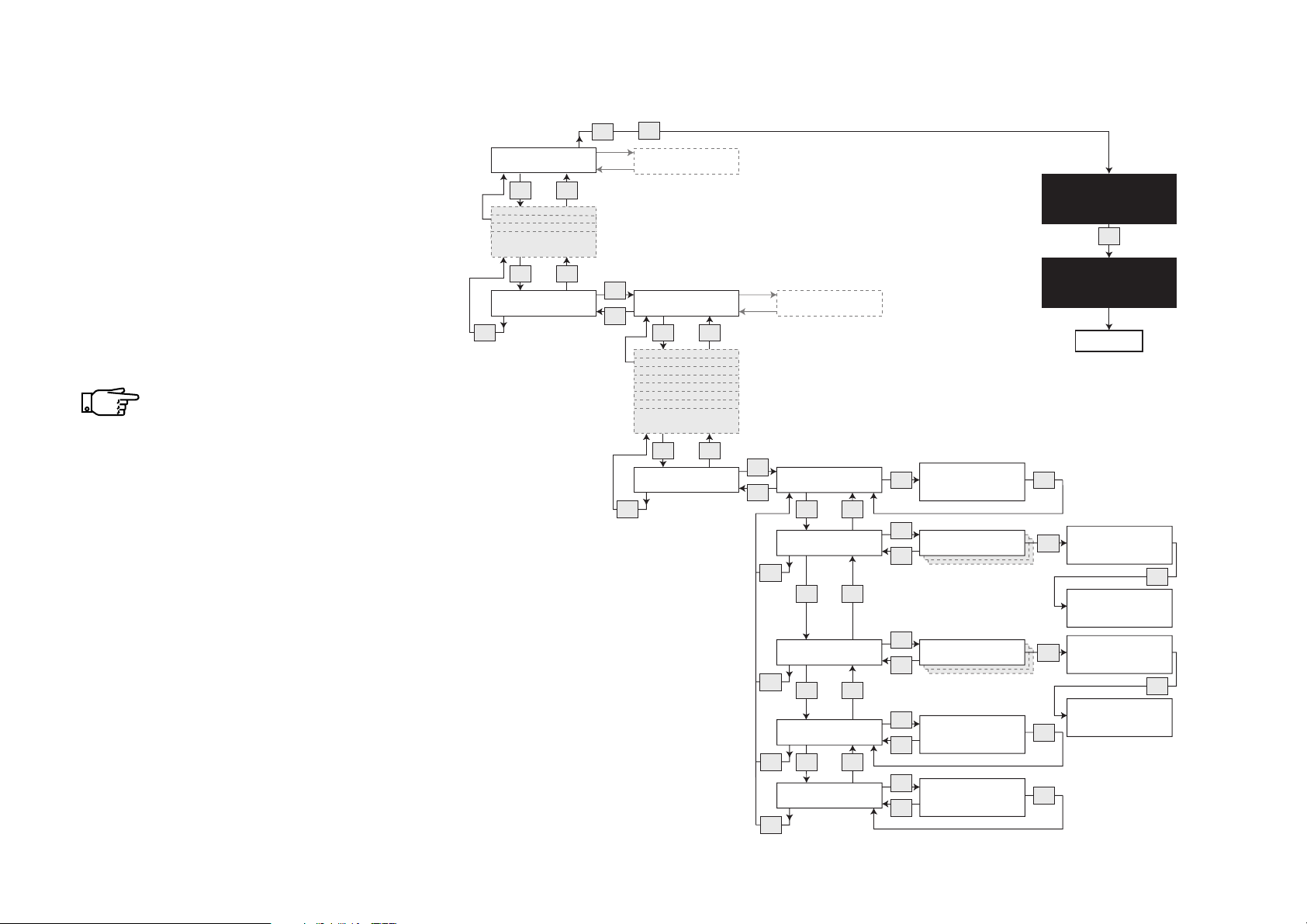
Additonal routines
FB 7100
PLU
Setting energy saving periods
• Follow this diagram to define one or
more energy saving periods (up to
seven periods).
• Setting a period means scheduling
the machine to reduce the
temperature for the boiler heating to
the temperature set in ‘Set
temperature’ and to switch off the
door light, if ‘Set doorlight’ is
enabled.
Temperature should never
be set below 65 °C.
Select “Menu” -> “Enter Password” -> “Test” -> “Operator” -> “Filling/Clean”
Esc
Esc
Filling / Clean
v
^
v
^
Machine settings
Esc
Sel
Set freevend, global
Esc
v
v
Energy saving
Esc
^
^
Sel
Save energy On/Off
Esc
v ^
Set day(s)
Esc
v ^
Set time
Esc
v ^
Set temperature
Esc
v ^
Set doorlight
Esc
Sel
Sel
Esc
Sel
Esc
Sel
Esc
Sel
Esc
Save energy
1=On / 0=Off_1
(-) (+) -> OK
Period 1
Period 1
Set temperature
Te mp .
: 000
(-) (+) -> OK
Set doorlight
1=On / 0=Off
(-) (+) -> OK
:
1
--MENU SELECTION--*Test
Operator
^ v Sel ESC
Esc
End
OK
Set start day:
Sel
(Mo=0, Su=6, All=7):1
(-) (+) Esc OK
Set end day:
(Mo=0, Su=6, All=7):1
(-) (+) Esc OK
Set start time:
Sel
Time: 00:00
(-) (+) -> OK
Set end time:
Time: 00:00
(-) (+) -> OK
OK
OK
OK
OK
76 FB 7100 PLUS 10.2011
Page 81

Display messages and trouble shooting
Display messages
If the vending machine shows one of the display messages mentioned below, please follow the suggestions for remedy under Corrective action. If the error remains, please call for service.
If a display message appears that is not mentioned here, please call for service.
Display message Corrective action
Cleaning required
Energy saving mode
Out of service
Rinse in progress...
Temperature low
Water level low
Base tray full
• The 'rinse time period' is exceeded. Clean the machine and
use one of the rinse functions, see “Rinsing machine” on
page 35
• Energy saving is active. At the press of a selection button, the
machine will return to vend mode. When the water is sufficiently heated, the machine is ready to dispense drinks.
• If the selection panel is left untouched for 10 minutes, the
machine will return to energy saving mode.
• Turn the machine off and on.
• Wait until machine has finished automatic rinse function.
• Wait until the water is heated sufficiently
(maximum 13 minutes)."
• Descale water inlet valve.
• Remove impurities from water filter. Replace if necessary.
• Remove impurities from water supply connection.
• Empty and clean base tray. Wipe it dry.
Drip tray full
Please remove cup
10.2011 FB 7100 PLUS 77
• Empty and clean drip tray. Wipe sensor dry.
• Remove cup from cup carrier.
Page 82

Display messages and trouble shooting
Display message Corrective action
Please remove pot
No SB1 (or 2) cyl. Pressure
SB Piston error
SB Scraper error
• Remove pot from pot platform.
• Remove blocking object from upper valve of brewing cylinder.
• Clean the brewer unit.
• Clean the brewer unit.
78 FB 7100 PLUS 10.2011
Page 83
Display messages and trouble shooting
Trouble shooting
If the vending machine does not function correctly and does not show a display message, check the following points before calling for service.
Fault Corrective action
Machine dispenses drinks for free
Flavour of drink is not satisfactory
Too little water or no water is dispensed
Only water is dispensed, no ingredient
• Check prices. Reset as necessary.
• Switch off free vend.
• Wrong ingredients. Use correct ingredients, i.e. correct whit-
ener for coffee and tea. Use only ingredients recommended
for vending machines.
• Check if components are clean. Replace and rinse thoroughly
as necessary.
• Ensure that canisters are located in their correct place.
• Ensure that hoses from ingredient canisters are located cor-
rectly in the dispense head.
• Ensure that water pipes are not blocked.
• Ensure that canister spout(s) is (are) open.
• Check if the ingredient canisters are empty. Refill as neces-
sary.
• Ensure that canisters are properly located.
• Ensure that canister coupling is fitted in canister.
• Check if the mixing funnels are blocked. Clean and relocate.
Ingredients are moist and become lumpy in canisters
10.2011 FB 7100 PLUS 79
• Remove dust from grid at rear of machine with a vacuum
cleaner from outside or take out fan and clean box from the
inside of the machine.
• Check for blockage around mixing funnels. Remove and reinstall components as necessary.
Page 84
Display messages and trouble shooting
Fault Corrective action
Mixing system overflows
Quantity of drink is inadequate or dispensing hose has a kink
Coins have difficulties being accepted
Machine is out of function
Liquid in bottom of machine
• Mixing funnel(s) blocked. Replace or clean blocked part(s).
Check if they are positioned correctly.
• Leak in mixing system. Check if the sealing ring is missing at
the mixing funnel.
• Replace or clean clogged components. Install hose of correct
length.
• Press the coin return button.
• Please confer with suppliers manual.
• Check the power supply cord and connect it correctly if
required.
• Check fuses outside of the machine, replace as necessary.
• Check if the drip tray or base tray is empty. Empty, wipe and
dry sensors.
• Ensure that the door is properly closed.
• One or more hoses of the dispense head are not in place.
• A whipper housing seal is missing.
The solid waste container is full with liquid or solid waste
Liquid escaping from machine
No drinks are delivered
Freshbrewer unit is malfunctioning
80 FB 7100 PLUS 10.2011
• Empty solid waste container.
• Ensure that solid waste container, trays, canisters, mixing fun-
nels and dispensing hoses are positioned correctly.
• Check if sensor for drip tray is soiled. Clean as necessary.
• Check if mixing funnels are blocked, and clean as necessary.
• Check the coffee/tea filter, and clean as necessary.
• Reassemble freshbrewer unit correctly.
Page 85

Page 86

Page 87

Page 88
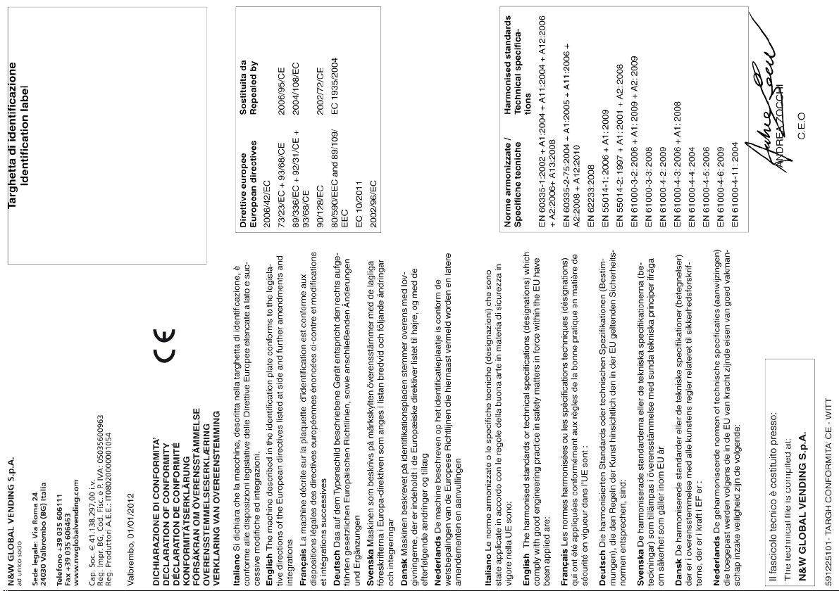
 Loading...