

Page 1

Operating instructions
Precision measuring device
Watch Expert
Read the instructions prior to performing any task!
Page 2

Witschi Electronic AG
Bahnhofstrasse 26
3294 Büren a.A.
Switzerland
T
elephone: +41 32 352 05 00
Fax: +41 32 351 32 92
Email: [email protected]
Internet: www.witschi.com
Translation of the original operating instructions
Wits-35286-CH, 3, en_GB
© 2016 Witschi Electronic AG
2
27.02.2018Precision measuring device Watch ...
Page 3
About this manual
Copyright
Customer service
This manual enables safe and efficient handling of the precision
measuring device (hereafter referred to as the “device” or “W
Expert”). The manual is part of the device and must be kept near
the device where it can be accessed by personnel at all times.
Personnel must have carefully read through and understood this
manual before starting work. The basic prerequisite for safe work is
compliance with all the safety, warning and procedural instructions
specified in this manual.
In addition, the local health and safety regulations and general
safety rules for the area in which the Watch Expert is used apply.
Illustrations in this manual are intended to aid basic understanding
and may deviate from the actual design.
The content of this manual is protected by copyright. It may be
used within the context of using the Watch Expert. No other use is
permitted without written approval from Witschi Electronic AG.
Your point of sale can provide you with technical information.
You can find your nearest point of sale on our website at “http://
www.witschi.com/de/firma/vertretungen”
We are also always interested in hearing from you about your
experiences of using the device and any information that could
help us improve our products.
atch
Customer service information
Address Witschi Electronic AG
Bahnhofstrasse 26
3294 Büren a.A.
Switzerland
Phone +41 32 352 05 00
Fax +41 32 351 32 92
e-mail [email protected]
Internet www.witschi.com
27.02.2018 Precision measuring device Watch ... 3
Page 4

Table of contents
Table of contents
1
Product description............................................................ 6
1.1 Watch Expert................................................................ 6
1.2 Microphone................................................................... 9
1.3 User interface............................................................. 10
1.4 Modes......................................................................... 12
1.5 Scope of delivery and accessories............................. 14
1.5.1 Scope of delivery..................................................... 14
1.5.2 Optional accessories............................................... 17
1.6 Technical data............................................................. 18
2 Safety................................................................................. 23
2.1 Symbols in this manual............................................... 23
2.2 Intended use............................................................... 24
2.3 Labels on the device................................................... 25
2.3.1 Labels on the power supply unit.............................. 25
2.3.2 Risk of material damage.......................................... 26
2.4 Owner’s responsibilities.............................................. 27
2.5 Personnel qualifications.............................................. 27
3 Storing the Watch Expert................................................. 29
3.1 Delivery and storage................................................... 29
3.2 Delivery....................................................................... 29
3.3 Transport inspection................................................... 29
3.4 Storage....................................................................... 30
4 Commissioning the Watch Expert................................... 31
4.1 Setting the inclination of the device............................ 31
4.2 Requirements for location........................................... 31
4.3 Connecting the power supply unit............................... 32
4.4 Connecting the microphone........................................ 33
4.5 Connecting the printer................................................ 33
4.6 Switching the Watch Expert on/off.............................. 34
5 Setting measuring parameters........................................ 36
5.1 Setting the beat number............................................. 36
5.2 Setting the lift angle.................................................... 39
5.3 Setting test mode........................................................ 42
5.4 Setting the integration time......................................... 43
5.5 Zooming in and out of the diagram............................. 44
5.6 Changing the display mode........................................ 44
6 Performing a measurement............................................. 45
6.1 Positioning the watch and starting a measurement
automatically
6.2 Monitoring the measured results................................ 47
6.3 Setting the signal strength.......................................... 49
6.4 Switching the speaker on/off....................................... 50
............................................................... 45
27.02.2018Precision measuring device Watch ...4
Page 5
Table of contents
6.5 Pausing and resuming the measuring procedure....... 50
6.6 Printing measured results........................................... 51
6.7 Generating screenshots.............................................. 52
6.8 Restarting a measuring procedure............................. 52
7 Configuring the user interface......................................... 53
7.1 Configuring touch buttons........................................... 55
7.2 Configuring the main display...................................... 56
7.3 Configuring microphone buttons................................. 58
7.4 Configuring a printer................................................... 61
7.5 Configuring system settings........................................ 62
7.6 Displaying device information..................................... 64
8 Servicing the Watch Expert............................................. 65
8.1 Safety during maintenance......................................... 65
8.2 Maintenance schedule................................................ 65
9 Performing firmware update............................................ 66
9.1 Registering Watch Expert........................................... 66
9.2 Updating firmware....................................................... 66
10 Troubleshooting................................................................ 68
10.1 Error messages on the touchscreen......................... 68
10.2 Troubleshooting........................................................ 68
11 Shutting down and disposing of the Watch Expert....... 69
Index................................................................................... 71
12
Appendix............................................................................ 74
A Declaration of conformity ............................................... 75
27.02.2018 Precision measuring device Watch ... 5
Page 6
Product description
Watch Expert
1 Product description
1.1
Watch Expert
Overview
Fig. 1: Watch Expert
No. Designation Function
1 Touchscreen
2 [Signal] LED display
3 Stand Adjustable stand for the Watch Expert (can be set to 6 incli-
n Displays for the numerical test results
n Displays for the graphical test results
n Displays for test progress
n Navigating through the menus
n Changing parameters
n LED flashes to the rhythm of the escapement noises.
nation angles)
27.02.2018Precision measuring device Watch ...6
Page 7
Product description
Watch Expert
Description
The Watch Expert is a precision measuring device for determining
the accuracy of mechanical watches.
The choice of parameters can be adjusted to suit the given requirements.
atch Expert automatically calculates measured values for
The W
rate deviation, amplitude and beat errors, and displays them
numerically.
With the aid of 4 different test modes, mechanical watches with the
following escapement types can be measured:
n Anchor escapement
n Duplex escapement
n Cylinder escapement
n Chronometer escapement
n Co-axial escapement
n AP escapement
in addition to watches with unusual beat noise.
The typical beat numbers of all common watches are recognised
automatically by the W
can be entered manually.
In addition to the “Diagram display mode” , which shows the measurement in the form of a diagram, the Watch Expert also features
the “VARIO display mode”, which shows rate accuracy and amplitude measurements and displays the smallest, largest and
resulting mean values, in each case.
With the aid of the pivoting microphone, a watch can be measured
in 12 different test position.
The switching screw on the rear side of the microphone ensures a
stable handling position for left and right-handed users.
Bluetooth functionality allows the device to be connected to a suitable printer so the measured results can be printed out. Bluetooth
functionality is possible using an optional dongle. Otherwise the
connection is via the serial interface.
atch Expert. Alternatively, the beat number
27.02.2018 Precision measuring device Watch ... 7
Page 8
Product description
Watch Expert
Connections and interfaces
Fig. 2: Rear
No.Designation Function
1 Rating plate
2 Microphone socket Connection socket for the microphone
3 Printer port
(RS232)/connection for calibration
4 Ethernet interface Connection for future applications
5 2x USB connec-
tions
6 Power supply Connection socket for the power supply
7 [I/O] switch Switches the Watch Expert on/off
8 Openings for the
stand
Identifying the device
n Connection for the thermal printer
Connections for USB sticks
unit
Openings for inserting the stand, in 6
dif
ferent positions
Ä
page 20
27.02.2018Precision measuring device Watch ...8
Page 9
1.2 Microphone
Microphone
Product description
Microphone
Fig. 3: Microphone
1 Pivoting microphone
2 Clamping jaws
The pivoting microphone (Fig. 3/1) provides 12 different test positions for measuring mechanical watches. The neoprene clamping
jaw (Fig. 3/2) can be adjusted in accordance with the size of the
watch. T
can be adjusted for left/right-hand users with the aid of the
switching screw (Fig. 3/3). The freely programmable keys (Fig. 3/4)
are used to navigate through the menu. Alternatively, the keys can
be assigned an individual function.
27.02.2018 Precision measuring device Watch ... 9
3 Switching screw for left/right-handed user
adjustment
4 Programmable keys
o ensure a stable hand resting position, the microphone
Page 10
Product description
User interface
1.3 User interface
Quick guide to the user interface
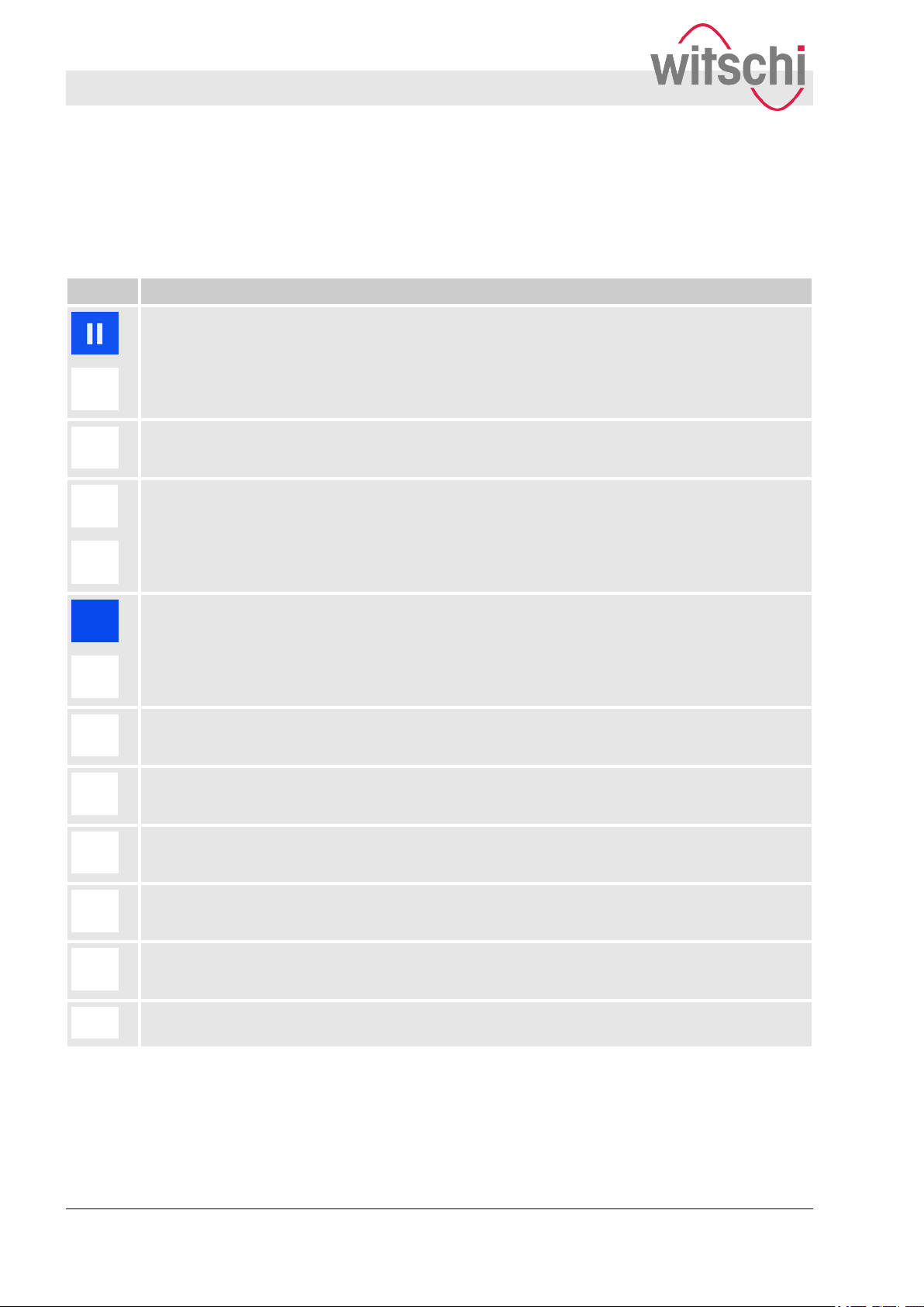
Symbol Function
Starting/pausing the measuring procedure.
Deleting the current measured values and restarting the measuring procedure.
Automatic recognition/manual control of the signal strength.
Switching the integrated speaker on/off.
The symbols and touch buttons on the software user interface
have the following functions:
Generating screenshots of the current view, where a USB stick is connected.
Sending the measuring results to a connected printer and printing them out.
1x, 2x, 4x, 8x and 16x enlargement of the diagram.
Adjustment of the integration time.
Opening the settings menu.
Opening the keypad for manual parameter entry.
27.02.2018Precision measuring device Watch ...10
Page 11
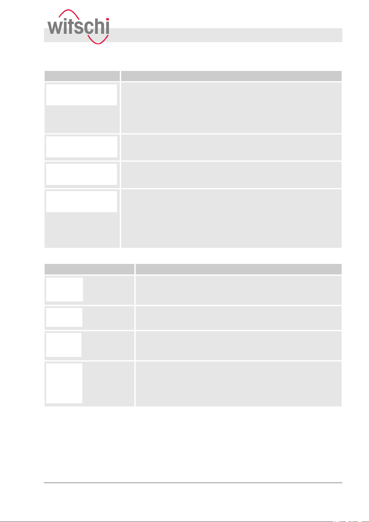
Touch button Function
Provides 3 different options for setting the beat number:
Product description
User interface
n Automatic: The beat number is recognised automatically
n Manual: The beat number (value between 3,600 b/h and 86,400 b/h) can
be entered manually.
n Frequency: The beat number is calculated automatically to obtain a rate
deviation of 0 s/d.
Provides the option of entering the beat time (value between 3,600 b/h and
86,400 b/h) manually
Provides the option of manually selecting/entering the lift angle (value between
10° and 90°).
Provides 4 different option for setting the test mode:
n Standard: Mode for watches with Swiss anchor escapement. T
the amplitude of the watch, the lift angle must be specified.
n Rate: Mode for rate measurement of watches with cylinder, duplex or chro-
nometer escapement, in addition to watches with unusual beat noise.
n Special 1 (co-axial):: Mode for watches with co-axial escapement.
n Special 2 (AP): Mode for watches with AP escapement.
Display element Function
.
.
o determine
Shows the rate deviation in s/d.
Shows the amplitude in °.
Shows the beat error (repère) in ms. If the zero-crossing is reached
during calibration (fine-tuning) the
beat error, e.g. Δ 0.9 ms.
Shows the currently-set test position of the watch. The flashing bars indicate that measured results are being received.
Δ symbol appears in addition to the
27.02.2018 Precision measuring device Watch ... 11
Page 12

Product description
Modes
Display element Function
Position window for the 6 main test positions. Shows, in diagram display
mode, which test position is currently being measured.
The following 12 test positions (designation of the main test position as
per NIHS 95-10/ISO 3158) are possible:
1.4 Modes
Overview of test modes
Selected parameters
The selected parameters are shown in green in the
main display and in the settings menu.
The Watch Expert provides 4 test modes that can be set in accordance with the escapement type of the watch to be tested.
27.02.2018Precision measuring device Watch ...12
Page 13
Product description
Modes
Test mode Additional information
Standard Mode for watches with Swiss anchor escapement.
o determine the amplitude of the watch, the lift
T
angle must be set.
Rate Mode for rate measurement of watches with cyl-
inder
, duplex or chronometer escapement, in addi-
tion to watches with unusual beat noise.
Special 1 (co-axial) Mode for watches with co-axial escapement.
Special 2 (AP) Mode for watches with AP escapement.
Determining the escapement type
ou can find out the escapement type of the watch
Y
that is to be tested by consulting the watch manufacturer.
Overview of display modes
Appearance Function
Diagram
VARIO
The Watch Expert provides two different display modes in which
various parameters are measured and displayed.
n Shows the rate deviation, the beat error and the
amplitude.
n During the measuring procedure, the measured
values are displayed as a diagram.
n It is possible to configure the diagram view
n The 6 position windows show the diagram as it
relates to the respective measuring position.
n If the measuring procedure has stopped, the meas-
ured values and the diagram can be shown in the
large display by tapping the small position windows.
Visualises the rate stability and amplitude over a longer
period.
During the measuring procedure, the current measured
values, including the mean, are shown over the entire
measuring period, in addition to the minimum and maximum rate and amplitude values.
.
27.02.2018 Precision measuring device Watch ... 13
Page 14
Product description
Scope of delivery and accessories > Scope of delivery
1.5 Scope of delivery and accessories
1.5.1
Scope of delivery
Fig. 4: Scope of delivery
No. Designation Function For details, see:
1 Watch Expert
2 Pilot microphone For signal transmission to the Watch Expert
3 Power supply unit (12 V
DC, 1.5 A)
4 Dust cover Protects the Watch Expert against build-up of dust
5 Stand For supporting the Watch Expert with 6 different
Connection to electricity supply
inclination angles.
Not shown in Fig. 4 but included in the scope of delivery:
n 1x manual
n 1x calibration certificate
n 1x warranty information
Ä
page 9
Ä
page 15
Ä
page 16
Ä
page 17
27.02.2018Precision measuring device Watch ...14
Page 15
Power supply unit
Product description
Scope of delivery and accessories > Scope of delivery
Fig. 5: Power supply unit
The power supply unit (Fig. 5) is used to connect the Watch Expert
to the power supply
.
Input values
Output values
n 100 – 240 V AC (inde-
pendent of the local mains
voltage)
n 50 – 60 Hz
n 18 V
n 12 V DC
n 1.5 A
A
27.02.2018 Precision measuring device Watch ... 15
Page 16

Product description
Scope of delivery and accessories > Scope of delivery
Dust cover
Fig. 6: Dust cover
The dust cover (Fig. 6) protects the Watch Expert against build-up
of dust when it is not being used.
27.02.2018Precision measuring device Watch ...16
Page 17
Stand
Product description
Scope of delivery and accessories > Optional accessories
Fig. 7: Stand
Using the stand (Fig. 7), the Watch Expert can be positioned at 6
ferent angles.
dif
Ordering contact
T
o order accessories or spare parts, contact your
Ä
point of sale (
You can find your nearest point of sale on our website at “http://www.witschi.com/de/firma/
vertretungen” .
page 3).
1.5.2 Optional accessories
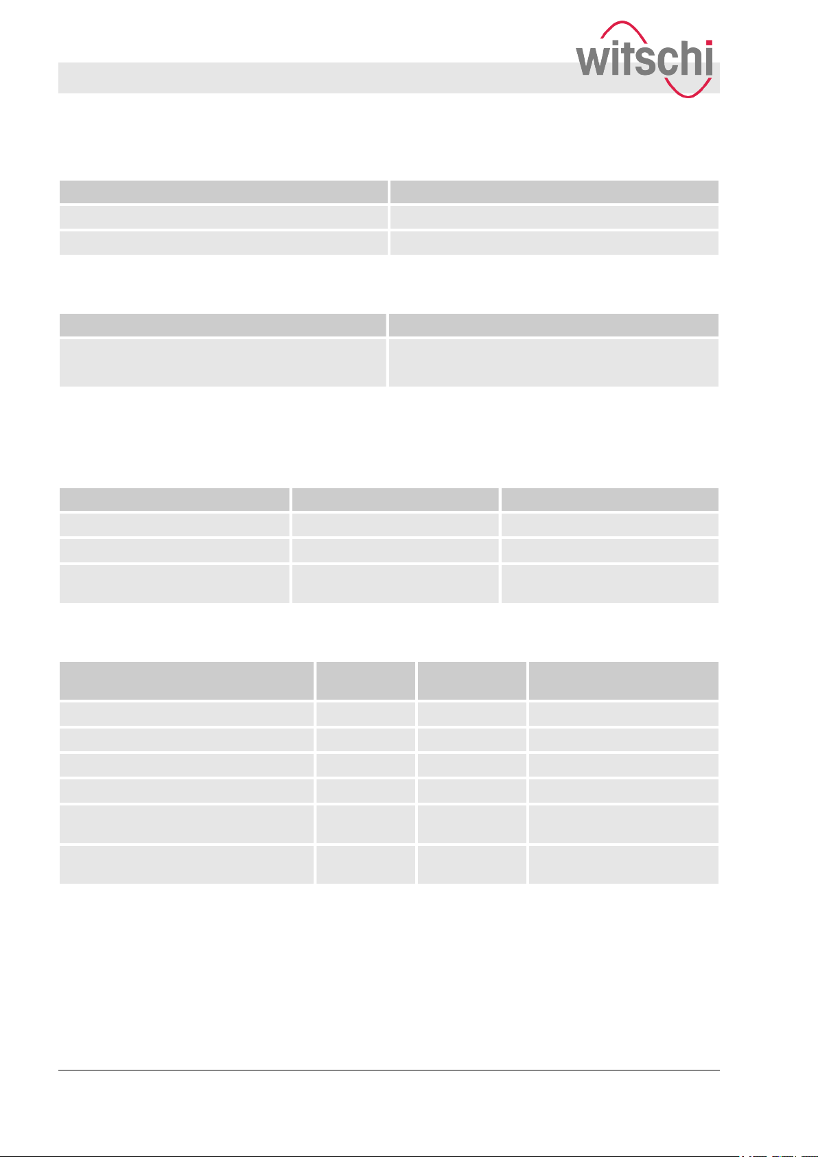
Printing
Item Item number
Thermal printer JB01-SLK-TE25-S
Thermal paper, roll for 740RS232 JB01-MM60-740RS
Bluetooth kit 95.1510
Bluetooth dongle JB15-BT900-US
Bluetooth module JB01-BT Module SLK-TE25
27.02.2018 Precision measuring device Watch ... 17
Page 18
Product description
Technical data
Sensor
Item Item number
Optoelectronic sensor for pendulum timepieces 13.1620
Stand for optoelectronic sensor 13.16.201
GPS receiver
Item Item number
Witschi GPS receiver 19.91PK1 (230 V~)
19.91PK2 (120 V~)
1.6 Technical data
Configuration
Device Type no. Notes
Watch Expert measuring device 11.2710
Pilot microphone signal sensor 13.1310
Portable power supply JA01-GT-41082-1812 Portable power supply, 100 – 240
V AC, 12 V DC, 18 W
Power supply
Parameters Nominal
value
Nominal voltage 230 V AC 100– 240 V
Mains frequency 50 / 60 Hz 45 – 65 Hz
Power consumption in operation 8 W
Standby with screen saver 4 W
Minimum warm-up period for measurement
Minimum warm-up period for adjustment 10 min No warm-up period from
none
Range Note
standby onwards
Measuring parameters
27.02.2018Precision measuring device Watch ...18
Page 19
Product description
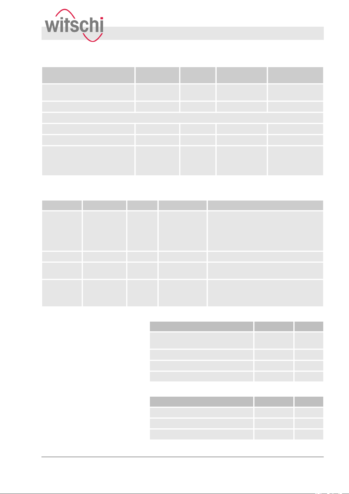
Technical data
Function Measuring
range
Time base in temperature range
10 – 50 ° C
Time base, 1st year ±0.03 s/d
Measurement of mechanical watches
Accuracy ±999 s/d 0.1 ±0.1 s/d
Beat error (repère) 9.9 ms 0.1 ms ±0.1 ms
Amplitude 70° - 360° 1° ±0.4° If the lift angle is
Communication interfaces
Designation Purpose Protocol Data rate Notes
USB Parameterisa-
tion, Print
Screen
Print via Bluetooth
±0.08 s/d TCXO
Resolution Accuracy Notes
incorrect, the amplitude value may
exceed 360°.
Ethernet for future applications
Printer / calibration
Printer Sewoo printer
Dimensions and weight
Mains supply connection values
Calibration PPS 1 pps ±90 ns Witschi CTB /GPS receiver
MARTEL 19200/8/none/1 Item no. JB01-SLK-TE25-S
MAR
TEL
printer
Data Value Unit
Weight (including pilot microphone
and mains adapter)
Width 197 mm
Height 164 mm
Depth 130 mm
Data Value Unit
Mains voltage 100 – 240 V AC
Mains frequency 50 – 60 Hz
Item no. JB01-740RS232
1.7 kg
Power consumption in operation 8 W
27.02.2018 Precision measuring device Watch ... 19
Page 20
Product description
Technical data
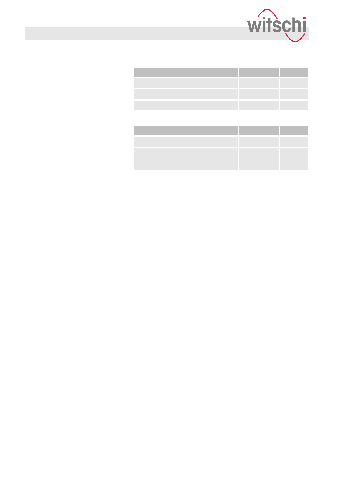
Power supply unit output values
Operating conditions
Watch Expert rating plate
Data Value Unit
Voltage 12 V DC
Current consumption, maximum 1.5 A
Power consumption, maximum 18 W
Data Value Unit
Temperature range 10 – 50 °C
Relative humidity, maximum 10 – 80 %, non-
condensing
The Watch Expert’s rating plate is located on the rear side of the
device and contains the following information:
n Manufacturer
n Device designation
ype
n T
n Serial number
n Year of manufacture
Fig. 8: Watch Expert rating plate
27.02.2018Precision measuring device Watch ...20
Page 21

Power supply unit rating plate
Product description
Technical data
The power supply unit’s rating plate contains the following information:
n Manufacturer
ype
n T
n Specification
Fig. 9: Power supply unit rating plate
27.02.2018 Precision measuring device Watch ... 21
Page 22

Product description
Technical data
27.02.2018Precision measuring device Watch ...22
Page 23
2 Safety
2.1
Symbols in this manual
Safety
Symbols in this manual
This section provides an overview of all the important safety
aspects that ensure personal protection and safe and trouble-free
operation. There are additional, task-specific warnings in the sections on the individual lifecycle phases.
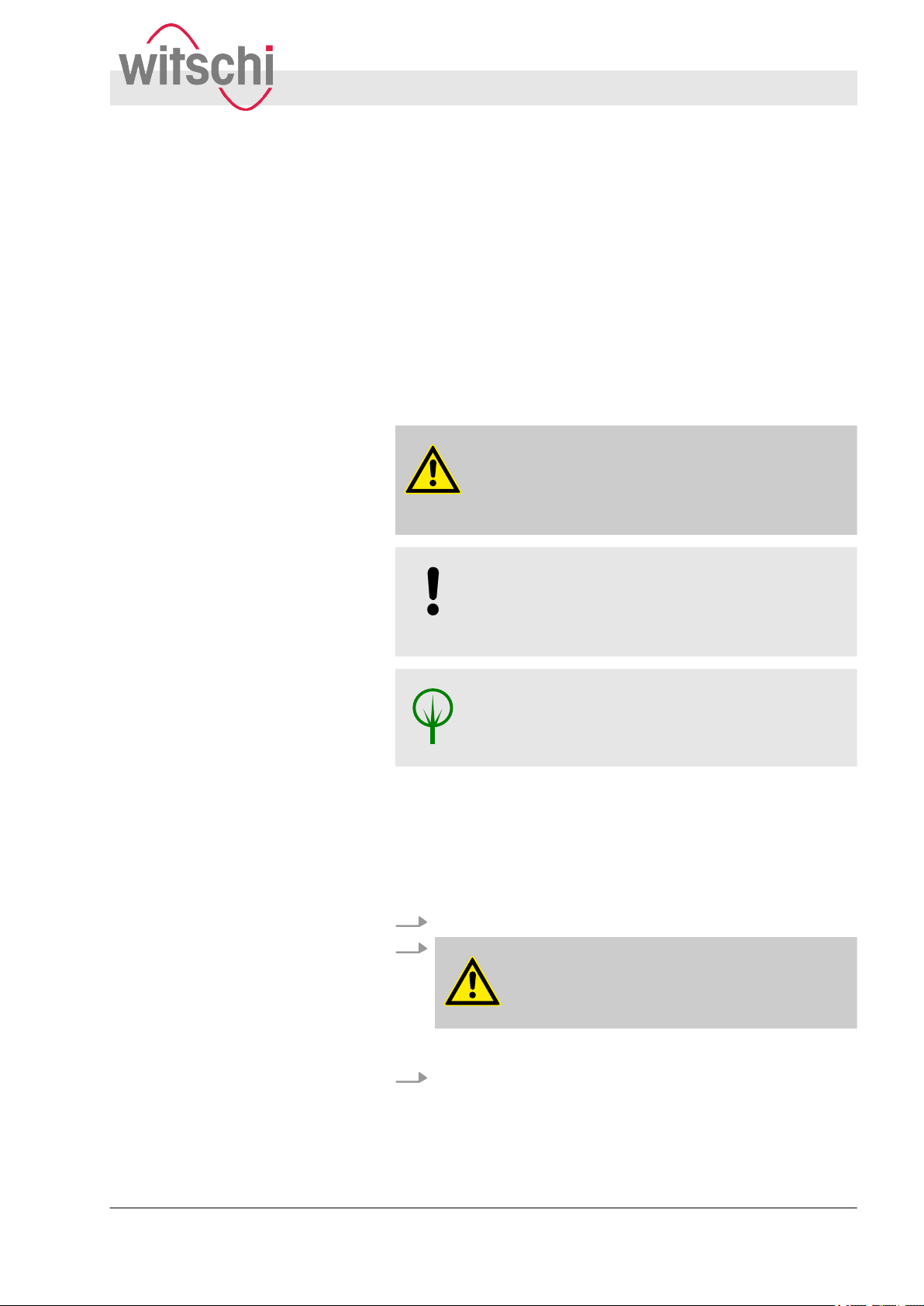
Safety indications and warnings
Warnings in instructions
Safety indications and warnings are identified by symbols in this
manual. The safety indications and warnings are introduced by
signal words that indicate the extent of the hazard.
CAUTION!
This combination of symbol and signal word indicates a potentially hazardous situation that can
entail minor injury if not avoided.
NOTICE!
This combination of symbol and signal word indicates a potentially hazardous situation that can
entail material damage if not avoided.
ENVIRONMENT!
This combination of symbol and signal word indicates possible hazards to the environment.
Warnings may relate to specific, individual instructions. Warnings
of this kind are embedded in the instruction so that they do not distract the reader
The signal words described above are used.
Example:
1. Loosen screw
2.
’s attention while performing the action in question.
.
CAUTION!
Risk of pinching on the cover!
Close the cover carefully.
3. T
27.02.2018 Precision measuring device Watch ... 23
ighten screw.
Page 24
Safety
Intended use
Tips and recommendations
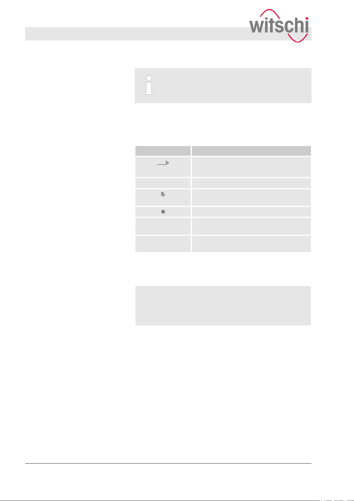
This symbol draws attention to useful tips and recommendations and to information that helps
ensure efficient and trouble-free operation.
Additional labels
2.2 Intended use
The following labels are used in this manual to draw attention to
instructions, results, lists, references and other elements:
Label Explanation
Step-by-step instructions
1., 2., 3. ...
ð
[Pushbutton] Control elements (e.g. buttons, switches),
“Touch button” Screen elements (e.g. names of windows,
The Watch Expert precision measuring device is intended solely
for measuring mechanical watches with the aid of a microphone
to determine rate deviation, amplitude and beat errors (repère).
With the aid of the clamping jaws on the microphone, the W
Expert is capable of testing mechanical wrist watches of all sizes.
Results of actions
References to sections of this manual and
other applicable documents
Lists without a fixed order
display elements (
touch buttons)
e.g. signal lamps)
atch
The intended use includes compliance with all the information in
this manual.
Any use beyond or other than the intended use shall be considered
misuse.
27.02.2018Precision measuring device Watch ...24
Page 25
Safety
Labels on the device > Labels on the power supply unit
NOTICE!
Danger in the event of misuse!
Misuse of the W
damage.
– Never clamp any objects other than watches
against the microphone.
– Only operate the device on a stable and hori-
zontal surface.
– Never set up or operate the Watch Expert in an
explosive atmosphere.
– Do not expose the device to direct sunlight or
extreme temperatures.
– Set up the device in a low-noise environment in
order to avoid distortion of the measured
values.
atch Expert can lead to material
2.3 Labels on the device
The following labels can be found on the device.
Calibration instruction
The calibration instruction on the underside of the device shows
when the device needs to be recalibrated. To ensure reliable measuring results, we recommend observing the proposed date for the
next calibration.
Electrical and electronic components
Electrical and electronic components in the device contain toxic
substances. The device must therefore be handed over to a municipal collection point for disposal or be disposed of by a specialist.
2.3.1 Labels on the power supply unit
The following labels can be found on the power supply unit.
27.02.2018 Precision measuring device Watch ... 25
Page 26
Safety
Labels on the device > Risk of material damage
Electrical and electronic components
The power supply unit must not be disposed of as household
waste, it must be handed over to a municipal collection point or be
disposed of by a specialist.
2.3.2
Short-circuit
Risk of material damage
NOTICE!
Material damage due to short-circuit!
Damage to the insulation on the power supply unit
cable or the power supply unit can result in a shortcircuit and damage to the W
– Only allow customer service to perform work
on the Watch Expert’s electronics.
– If the power supply unit cable or power supply
unit are damaged, disconnect the power supply
unit plug and have the unit repaired.
– Route the power supply unit cable so that it
cannot be damaged by external influences.
– Before any cleaning, maintenance or trouble-
shooting work, disconnect the power supply
unit plug.
– When disconnecting the power supply unit,
only pull on the plug itself, never pull on the
cable.
– Always keep access to the power socket clear.
– Keep moisture away from live parts. Moisture
can result in short-circuits.
– Never immerse the device in water.
atch Expert.
Opening the housing
NOTICE!
Material damage due to opening the housing!
Opening the housing causes a risk of damaging
components inside the device or damaging the
housing.
– Never open the device housing yourself.
In the event of malfunctions or problems that
–
cannot be solved with the help of this manual,
contact the manufacturer.
27.02.2018Precision measuring device Watch ...26
Page 27
2.4 Owner’s responsibilities
Safety
Personnel qualifications
Opening the housing results in a loss of warranty.
Owner’s obligations
The device is intended for commercial use. The owner of the
device is subject to the statutory obligations of occupational health
and safety
In addition to the safety indications and warnings in this manual,
you must comply with the safety, occupational health and safety
and environmental protection requirements that apply to the device’s area of application.
The following applies in particular:
n The owner must learn about the applicable occupational health
n Throughout the entire period that the device is in operation, the
n The owner shall ensure that all persons who handle the device
n The owner shall ensure that the service intervals described in
n The owner shall ensure that the service intervals for the com-
.
and safety requirements and perform a risk assessment to
identify additional hazards resulting from the specific working
conditions at the device’s site of operation. The owner shall use
this information to create operating instructions for the device.
owner shall check that the operating instructions created by the
owner comply with the current versions of regulations and must
adapt the instructions as necessary.
have read and understood this manual. In addition, the owner
shall train personnel at regular intervals and inform them of
potential risks.
this manual are complied with.
ponents are complied with.
2.5 Personnel qualifications
This manual stipulates the following qualifications for the operator:
Customer service
Certain work may only be performed by Customer Service. Customer Service has been trained extensively for all work performed
on measuring devices.
ork that is the specified task of Customer Service personnel may
W
not be performed by unauthorised personnel. Contact Customer
Service when this work is due.
27.02.2018 Precision measuring device Watch ... 27
Page 28

Safety
Personnel qualifications
Operator
The operator of the device has all the necessary knowledge and
training to handle watches. In addition, the operator has been
instructed by the owner about the tasks entrusted to him or her and
about possible hazards in the event of improper behaviour
operator may only perform tasks that go beyond normal operation
where this is provided for in the manual and the owner has specifically entrusted the operator with such tasks.
. The
27.02.2018Precision measuring device Watch ...28
Page 29
3 Storing the Watch Expert
3.1
Delivery and storage
Improper transport
Storing the Watch Expert
Transport inspection
CAUTION!
Risk of injury and material damage due to
improper transport!
In the event of improper transport, the device may
fall or topple. This can cause serious injuries or
major material damage.
– Always transport packages upright and never
throw them.
–
Only remove packaging immediately before
first use.
– Only transport the device when it is shut down
Ä
page 69).
(
– Always use both hands when transporting the
device.
3.2 Delivery
3.3 Transport inspection
The Watch Expert is delivered by a local logistics company. All the
components included in the scope of delivery are delivered
together in a single package.
Upon receipt of the delivery, check it immediately to ensure that it
is complete and undamaged.
If there is any visible external transport damage, proceed as follows:
n Do not accept the delivery
n Make a note of the scope of damage on the carrier’s delivery
note.
n Lodge a complaint.
Lodge a complaint for each defect as soon as it is
identified. Claims for damages can only be made
within the applicable claim periods.
.
27.02.2018 Precision measuring device Watch ... 29
Page 30

Storing the Watch Expert
Storage
3.4 Storage
Store the device and packages under the following conditions:
atch Expert is shut down (Ä page 69).
n W
n Do not store outdoors.
n Store in a dry and dust-free condition.
n Do not expose to any aggressive media.
n Protect against sunlight.
n Avoid mechanical shocks.
n Do not place anything on top of the device packaging.
n Storage temperature: -20 °C – +70 °C
n Relative humidity: 10 % – 80 %, no condensation.
27.02.2018Precision measuring device Watch ...30
Page 31
Commissioning the Watch Expert
4 Commissioning the Watch Expert
4.1
Setting the inclination of the device
The inclination of the display unit can be adjusted to the requirements and lighting conditions of the workplace.
Different inclinations can be set by inserting the adjustment stand
on the reverse side into the intended openings at different heights.
The stand can be rotated 180° to allow the display unit to be set up
with 6 possible inclinations.
4.2 Requirements for location
Distortion of results
NOTICE!
An unsuitable location may distort test results!
T
o achieve precise test results, the following
requirements must be fulfilled:
– Do not position the Watch Expert and test
object in the vicinity of radiators or open windows.
– Do not place the Watch Expert and test object
in direct sunlight.
– Operate the Watch Expert on a level, horizontal
surface.
– Set up the Watch Expert in a low-noise envi-
ronment.
Requirements for location
27.02.2018 Precision measuring device Watch ... 31
Page 32
Commissioning the Watch Expert
Connecting the power supply unit
4.3 Connecting the power supply unit
Use of a suitable power supply unit
NOTICE!
Risk of material damage if an unsuitable power
supply unit is used!
Using an unsuitable or damaged power supply unit
can result in a short-circuit. This can damage the
device.
– Only use the power supply unit provided.
–
Route the power supply unit cable so that it
cannot be damaged by external influences.
Checking the mains voltage
Fig. 10: Mains connection
Personnel:
1. Make sure that the local mains voltage is appropriate for the
power supply unit.
Input values
2. Insert the power supply unit adapter into the mains connection (Fig. 10/1).
3. Connect the power supply unit to the local mains supply
The power supply is now connected.
ð
n
Operator
n 100 – 240 V AC
n 50 – 60 Hz
n 18 V
A
.
27.02.2018Precision measuring device Watch ...32
Page 33
4.4 Connecting the microphone
Use of a suitable microphone
Commissioning the Watch Expert
Connecting the printer
NOTICE!
Risk of material damage if an unsuitable micro-
phone is used!
Using an unsuitable or damaged microphone can
result in a short-circuit. This can damage the
device.
– Only use the supplied microphone.
–
Place the microphone on an even surface.
Fig. 11: Microphone socket
4.5 Connecting the printer
Thermal printer
Personnel:
Insert the microphone cable into the microphone socket
(Fig. 1
1/1).
Observe the correct alignment of the
microphone cable
When connecting the microphone cable,
observe the notch on the socket and align
the cable accordingly
carefully and do not use force!
The microphone is connected to the W
ð
The thermal printer is used to print out test results. The thermal
printer is connected to the W
Ä
page 34).
(
The test results can be printed out in the following ways:
n Connect the Witschi thermal printer directly to the Watch
Expert and begin using it.
n
Operator
. Connect the cable
atch Expert.
atch Expert via the printer port
27.02.2018 Precision measuring device Watch ... 33
Page 34
Commissioning the Watch Expert
Switching the Watch Expert on/off
Only perform the following steps if you wish to use
a thermal printer
.
Personnel:
Materials:
1. Connect the printer cable to the thermal printer
2. Insert the printer cable into the printer port (
The thermal printer is now connected.
ð
Fig. 12: Printer port
4.6 Switching the Watch Expert on/off
Operator
n
Printer cable
n
.
Fig. 12/1).
Consult the manufacturer’s documentation before
using the thermal printer
Another possibility is to connect the Watch Expert
to the printer via a Bluetooth connection using a
Bluetooth kit (T
ype no. 95.1510).
.
Switching on the Watch Expert
Fig. 13: Switching on the Watch
Expert
Personnel:
Requirement:
n The W
atch Expert has been commissioned correctly (Ä page
31).
Switch on the Watch Expert by setting the [I/O] switch
(Fig. 13/1) to [I].
The welcome screen is displayed.
ð
If the wrong language is set, set the language
Ä
page 62).
(
n
Operator
27.02.2018Precision measuring device Watch ...34
Page 35
Switching off the Watch Expert
Personnel:
Commissioning the Watch Expert
Switching the Watch Expert on/off
Operator
n
Fig. 14: Switching off the Watch
Expert
1. Switch of
(Fig. 14/1) to [O].
2. Cover the W
f the Watch Expert by setting the [I/O] switch
If you are not planning to use the Watch Expert for
a longer period, shut it down (Ä page 69).
atch Expert with the dust cover.
27.02.2018 Precision measuring device Watch ... 35
Page 36
Setting measuring parameters
Setting the beat number
5 Setting measuring parameters
5.1
Setting the beat number
“Mode” touch button
In the main display, using the “Mode” touch button, it is possible to
determine whether the beat number is to be recognised automatically or entered manually
of a watch is determined for a rate deviation of 0 s/d.
Press the “Mode” touch button.
A submenu with 3 options is opened.
ð
The following modes are available:
Modus (Mode) Function
Automatic The most common beat num-
Manually If the “Manual” mode is
. In “Frequency” mode, the beat number
bers are pre-programmed into
atch Expert (between
the W
12,000 b/h and 72,000 b/h),
allowing for the beat number to
be recognised automatically as
soon as the watch is placed
against the microphone.
selected for the beat number
the beat numbers in the range
from 3,600 b/h to 86,400 b/h
can be selected or entered
manually. Information on the
beat number to be entered for
the test watch can be obtained
from the watch manufacturer or
downloaded from
http://www.witschi.com/assets/
files/sheets/Scope
Schlagzahlen def 2-3.pdf.
,
Frequency The Watch Expert determines
the beat number to obtain a
rate deviation of 0 s/d. Using
this function, reference values
for measurements and, with
that, a reference clock, can be
created. The determined beat
number can be entered as a
manual value for further measurements.
27.02.2018Precision measuring device Watch ...36
Page 37
Setting measuring parameters
Setting the beat number
Selecting a beat number in accordance with the
watch manufacturer
To find out the beat number to be entered for the
test watch, contact the watch manufacturer. Otherwise, a manufacturer list with parameter data can
be downloaded from
http://www.witschi.com/assets/files/sheets/Scope
Schlagzahlen def 2-3.pdf.
’s specifications
27.02.2018 Precision measuring device Watch ... 37
Page 38
Setting measuring parameters
Setting the beat number
Selecting a beat number manually
As an alternative to automatic recognition, the beat number can
also be selected manually from the touch button selection list.
Requirement:
n The “Manual” mode is set.
Adding a beat number to the selection list
Under “Settings > Parameters > Beat number”, it is
possible to set the beat numbers that are shown in
the main display under the “Beat number” touch
button. Beat numbers between 3,600 b/h and
86,400 b/h) can be selected.
1. Press the “Beat number” touch button.
A selection list of the available beat numbers is shown.
ð
Entering a beat number manually
Fig. 15: Selecting a beat number manually
2. Select the desired beat number from the list in accordance
with the watch manufacturer
The selected beat number is highlighted green. The
ð
selection window is closed.
1. Press the “123” touch button.
A keypad appears.
ð
’s specifications.
27.02.2018Precision measuring device Watch ...38
Page 39
Setting measuring parameters
Setting the lift angle
Fig. 16: Entering a beat number manually
2. Enter the desired beat number in accordance with the watch
manufacturer
3. Confirm by pressing the “Enter” touch button.
Measurements will then be carried out using the set beat
ð
number
’s specifications.
.
5.2 Setting the lift angle
Setting the lift angle
The “Lift angle” touch button provides a list of options for setting
the lift angle for escapement. The amplitude is calculated with the
aid of the lift angle and can be set in accordance with the watch
.
caliber
Selecting the lift angle in accordance with the
clockwork manufacturer
Incorrect setting of the lift angle leads to an incorrect amplitude value. To find out which lift angle
should be entered for the watch that is to be
tested, contact the clockwork manufacturer. Otherwise, a manufacturer list with parameter data can
be downloaded from the Witschi website at:
www.witschi.com/de/service/downloads/
technische-infos.html.
’s specifications
27.02.2018 Precision measuring device Watch ... 39
Page 40
Setting measuring parameters
Setting the lift angle
Selecting a lift angle manually
Adding a lift angle to the selection list
Under “Settings > Parameters > Lift angle”, it is
possible to set the lift angles that are shown in the
main display under the
Lifting angles between 10° and 90° can be
selected.
1. Press the “Lift angle” touch button.
A list of the selected lift angles is shown, along with the
ð
keypad symbol.
“Lift angle” touch button.
Entering a lift angle manually
Fig. 17: Selecting a lift angle manually
2. Select the desired lift angle in accordance with the watch
manufacturer
The selected lift angle is highlighted green.
ð
1. Press the “123” touch button.
A keypad appears.
ð
2. Enter the desired lift angle in accordance with the watch
manufacturer
’s specifications.
’s specifications.
Entering values with decimal places
It is also possible to enter lift angle values
with decimal places.
27.02.2018Precision measuring device Watch ...40
Page 41

Setting measuring parameters
Fig. 18: Entering a lift angle manually
3. Confirm by pressing the “Enter” touch button.
Measurements will then be carried out using the set lift
ð
angle.
Setting the lift angle
27.02.2018 Precision measuring device Watch ... 41
Page 42
Setting measuring parameters
Setting test mode
5.3 Setting test mode
est mode” touch button provides a list of options for setting
The “T
the type of escapement that is to be measured.
1. Press the “T
A submenu with four options appears (
ð
Fig. 19: Selecting test mode
2. Select a test mode in accordance with the watch manufactur-
’s specifications.
er
The selected program is highlighted green.
ð
est mode” touch button.
Ä
page 12).
Selecting a test mode in accordance with the
clockwork manufacturer
You can find out the escapement type of the watch
that is to be tested by consulting the watch manufacturer.
’s specifications
27.02.2018Precision measuring device Watch ...42
Page 43
5.4 Setting the integration time
The mean values of the measured results are calculated with the
aid of the integration time.
The integration time applies both to the Diagram view and the
V
1. Press the “Integration time” touch button.
ario view.
ð
Setting measuring parameters
Setting the integration time
Under “Settings > Parameters > Integration time” ,
it is possible to set the integration times that are
shown in the main display under the
time” touch button. The following integration times
can be selected: 4A, 2 s, 4 s, 6 s, 8 s, 10 s, 20 s,
30 s, 40 s, 60 s.
A selection list with the available integration times is
shown.
“Integration
Fig. 20: Selecting an integration time
2. Select the desired integration time.
The selected integration time is highlighted green. Meas-
ð
ured results are calculated and displayed for every four
half-vibrations.
Optimised representation of rate and amplitude
values
T
o display smaller oscillations in rate and amplitude values in greater detail, we recommend
selecting shorter integration times.
27.02.2018 Precision measuring device Watch ... 43
Page 44

Setting measuring parameters
Changing the display mode
5.5 Zooming in and out of the diagram
In order to better recognise irregularities in the diagram, the zoom
function can be used to increase the size of the diagram by up to
16 times. The larger the zoom factor (between 1x and 16x), the
greater the distance between the lines of the diagram.
Requirement: The diagram display mode is selected.
1. Press the “Zoom in” touch button.
A selection list is shown.
ð
Fig. 21: Changing the size of the diagram
2. Select the desired zoom factor
5.6 Changing the display mode
The Watch Expert provides two different display modes. Both show
the most current measured rate deviation, amplitude and beat error
(repère). The display modes differ in the following ways:
n In the diagram display mode, the rate deviation and beat error
n In the VARIO display mode, rate stability and amplitude are
To switch between diagram and VARIO display modes, proceed as
follows:
.
The selected zoom factor is highlighted green.
ð
(repère) are measured and shown in the form of a diagram
Ä
page 13).
(
measured over a longer time period. At the same time, the
smallest, largest and resulting mean values are shown
Ä
page 13).
(
Touch the main display.
The display mode is changed. The desired display is
ð
shown.
27.02.2018Precision measuring device Watch ...44
Page 45
Performing a measurement
Positioning the watch and starting a measurement automatically
6 Performing a measurement
6.1
Positioning the watch and starting a measurement automatically
Positioning the watch in the
clamping area
Personnel:
Requirement:
n The W
1. Pull the clamping jaw (Fig. 22/2) outwards.
atch Expert is switch on (Ä page 34 ).
Positioning the watch correctly
If the watch is not positioned correctly, the test
results may be distorted.
n
Operator
Fig. 22: Microphone clamping jaw
Clamping the entire watch/clockwork
Fig. 23: Entire watch clamped
2. Place the watch onto the clamping area so that the crown of
the watch is positioned against the signal sensor (
Carefully close the clamping jaw.
The LED light flashes to the rhythm of the watch beats.
ð
The measuring procedure is started.
Alternatively, the measurement can be
started via the button.
Fig. 22/1).
27.02.2018 Precision measuring device Watch ... 45
Page 46
Performing a measurement
Positioning the watch and starting a measurement automatically
Fig. 24: Clockwork clamped in cup
Clamping clockwork (without a
housing)
3. Place the clockwork onto the clamping area so that the plate
is positioned above the signal sensor (
close the clamping jaw.
ð
Fig. 25: Crown of clockwork positioned above the signal sensor
Fig. 22/1). Carefully
The LED light flashes to the rhythm of the watch beats.
The measuring procedure is started.
Alternatively, the measurement can be
started via the button.
27.02.2018Precision measuring device Watch ...46
Page 47
6.2 Monitoring the measured results
Diagram display mode
Fig. 26: Diagram display mode
In the diagram display mode, the rate deviation and the beat error
(repère) are shown in diagram form (
Rate (Fig. 26/1), beat error (repère) (Fig. 26/2) and amplitude
(Fig. 26/3) are illustrated numerically.
The flashing rectangles (Fig. 26/4) show that a measured value is
being received. The letters below indicate the test position of the
microphone.
In order to better recognise irregularities, the diagram can be
enlarged using the zoom function (Fig. 26/5).
The 6 position windows (Fig. 26/7) show the diagram in the respective measuring position. If the measuring procedure is stopped, the
measured values and the diagram can be shown in the large display by tapping the small position windows.
Performing a measurement
Monitoring the measured results
Fig. 26/6).
Printing measured results/generating screenshots
For the purposes of evaluating the measured
values, the current view can be printed or a
Ä
screenshot can be generated (
27.02.2018 Precision measuring device Watch ... 47
page 51).
Page 48

Performing a measurement
Monitoring the measured results
VARIO display mode
Fig. 27: VARIO display mode
In the VARIO display mode, the rate (Fig. 27/1), beat error (repère)
(Fig. 27/2) and amplitude (
The flashing rectangles (Fig. 27/4) show that a signal is being
received. The elapsed measuring time is displayed underneath
(Fig. 27/4).
During the measuring procedure, the smallest, largest and
resulting mean measured values are shown for rate stability
(Fig. 27/5) and amplitude (Fig. 27/6).
Fig. 27/3) are illustrated numerically.
Evaluation of rate quality and amplitude
– The difference between the smallest and
largest rate value (Fig. 27/5) is an indicator for
the rate quality of the watch. The smaller the
difference, the better the rate stability.
– The mean value is an indicator of the compar-
ison quality (control) of the clockwork.
27.02.2018Precision measuring device Watch ...48
Page 49
6.3 Setting the signal strength
Using the “Signal amplifier” touch button, the signal strength of the
microphone can be set.
If the signal strength is set to “Auto” , the W
cally recognises and controls the signal for most watches.
If the signal is too weak or too strong, an “unclean” diagram
appears in the diagram display mode. In such cases, it is possible
to control the signal sensitivity manually.
Automatic recognition of the signal
strength
In order to recognise the signal strength automatically, proceed as
follows:
1. Press the “Signal amplifier” touch button.
Performing a measurement
Setting the signal strength
atch Expert automati-
A signal controller appears in the main display
ð
.
Setting the signal strength manually
Amplifying the signal
Decreasing the signal
2. Press the “Auto” touch button on the signal controller
The signal strength is recognised automatically.
ð
3. Press the “Signal amplifier” touch button.
The signal strength is saved. The signal controller is
ð
hidden automatically after approx. 3 seconds.
In order to set the signal strength manually
1. Press the “Signal amplifier” touch button.
A signal controller appears in the main display
ð
2. T
3. T
o amplify the signal, push the control switch upwards.
Unclean diagram (signal too weak)
If the first signal in the signal package is too
weak, proper signal recognition can be made
possible by amplifying the signal. However
this increases the sensitivity of the microphone to unwanted background noise.
o decrease the signal strength, push the control switch
downwards.
, proceed as follows:
.
.
,
Unclean diagram (signal too strong)
Unclean diagrams can result from unwanted
background noise. By reducing the strength
of the signal, background noise can be eliminated.
4. Press the “Signal amplifier” touch button.
The signal strength is saved. The signal controller is
ð
hidden. The signal controller is hidden automatically after
approx. 3 seconds.
27.02.2018 Precision measuring device Watch ... 49
Page 50
Performing a measurement
Pausing and resuming the measuring procedure
6.4 Switching the speaker on/off
The speaker can be switched on and off by pressing the speaker
symbol. With the loudspeaker activated, watch irregularities can be
heard.
Speaker switched on
1. Press the “Speaker” touch button.
The speaker is switched on. The symbol is shown as fol-
ð
lows:
Speaker switched off
2. Press the “Speaker” touch button.
The speaker is switched of
ð
6.5 Pausing and resuming the measuring procedure
As soon as the watch is positioned and clamped with the clamping
Ä
jaw (
Using the pause function, the measuring procedure for the analysis
of the determined values can be paused.
page 45), the measuring procedure starts automatically.
f.
Pausing the measuring procedure
Resuming the measuring procedure
Avoidance of background noise
The measuring procedure can be paused to prevent the microphone recording background noise
when the test position is changed.
1. Press the “Play/Pause” touch button.
The measuring procedure is paused.
ð
Printing measured results
If the measuring procedure is paused,
the current view can be printed (
51).
2. Press the “Play/Pause” touch button.
The measuring procedure is resumed from the same
ð
point.
Ä
page
27.02.2018Precision measuring device Watch ...50
Page 51
6.6 Printing measured results
Performing a measurement
Printing measured results
For the purposes of printing measured results or generating
screenshots, a thermal printer can be connected to the W
Expert via Bluetooth or a printer cable.
Requirement:
atch
Printing measured results
n A printer is connected to the W
1. Press the “Play/Pause” touch button.
The measuring procedure is paused.
ð
2. Press the “Print” touch button.
The current display is sent to the printer
ð
printed.
Printing during the measuring procedure
If the “Print” touch button is pressed during the
measuring procedure, the currently displayed
numerical values for rate, amplitude and beat error
are printed.
Editing the header of the printout
Under “Settings > Printer > Printer Line (1-4)” individual lines of header text can be added to the
printouts, with 20 characters per line (Ä page
61 ).
atch Expert.
. The display is
27.02.2018 Precision measuring device Watch ... 51
Page 52
Performing a measurement
Restarting a measuring procedure
6.7 Generating screenshots
Screenshots of measured results
Using the screenshot function, images of the current view can be
generated.
Requirement:
n A USB stick is connected to the W
Press the “Print” touch button.
A screenshot of the current view is saved to the USB
ð
stick.
6.8 Restarting a measuring procedure
Using the restart function, the determined measured values can be
deleted and the measuring procedure can be restarted.
atch Expert
Accessing screenshots
The generated screenshots are saved to the USB
stick in PNG format. To access the screenshots,
remove the USB stick from the Watch Expert and
connect it to a computer.
Press the “Restart” touch button.
The measuring procedure is restarted. The previously
ð
determined measured values are deleted.
27.02.2018Precision measuring device Watch ...52
Page 53

7 Configuring the user interface
In the settings menu, you can configure the main display, touch
buttons, microphone buttons and printer
Opening the settings menu
Press the “Settings” touch button.
The settings menu is shown.
ð
Configuring the user interface
.
Exiting the settings menu
Fig. 28: Settings menu
Press the “Measurement” (Fig. 29/1) touch button.
The settings are saved. The main display is shown.
ð
Fig. 29: Exiting the settings menu
27.02.2018 Precision measuring device Watch ... 53
Page 54

Configuring the user interface
Saving settings
Settings are saved automatically and remain active
after a restart.
27.02.2018Precision measuring device Watch ...54
Page 55
7.1 Configuring touch buttons
Configuring the user interface
Configuring touch buttons
Adding parameters to the selection
list
Appearance Additional information
Beat number Beat numbers between 3,600 b/h and 86,400 b/h
Lift angle Lifting angles between 10° and 90° can be added to
Using the “Parameters” tab, it is possible to set which parameters
are to be displayed in the selection lists of the touch buttons in the
main display
The following touch buttons can be configured:
.
can be added to the touch button selection list.
the touch button selection list.
Integration time The following integration times can be added to the
touch button selection list:
n 4 A
n 2 s
n 4 s
n 6 s
n 8 s
n 10 s
n 20 s
n 30 s
n 40 s
n 60 s
27.02.2018 Precision measuring device Watch ... 55
Page 56

Configuring the user interface
Configuring the main display
7.2 Configuring the main display
Customising the appearance of the
main display
The main display can be configured using the “Screen” tab.
The following settings can be adjusted:
Result order
Highlighting parameters
The selected parameters are highlighted green
and displayed in the touch button selection lists in
the main display
.
Fig. 30: Setting the display sequence of the current measured
values
Two orders are available:
n Rate deviation/beat error (repère)/amplitude
n Rate deviation/amplitude/beat error (repère)
27.02.2018Precision measuring device Watch ...56
Page 57
Positions
Configuring the user interface
Configuring the main display
Fig. 31: Setting test position designation types
There are two test position designation types available
Watch position
n CH/CB/9H/6H/3H/12H
n ZO/ZU/KU/KL/KO/KR
Fig. 32: Setting the watch position
There are two watch positions available:
n CH (Dial side up)
n CB (Dial side down)
This function defines the position in which the watch has been
clamped so as to determined the correct positioning of the watch.
27.02.2018 Precision measuring device Watch ... 57
Page 58

Configuring the user interface
Configuring microphone buttons
Position windows
Line width
Fig. 33: Hiding/displaying the position windows of the measured
test positions in the main display (only in the diagram display
mode)
The position windows of the measured test positions can be displayed/hidden in the main display
hidden, the test positions do not appear on the printout.
. If the position windows are
7.3
Configuring microphone buttons
Configuring microphone buttons
Fig. 34: Determination of line thickness (only in Diagram display
mode)
The diagram line is shown with different thicknesses.
The following settings are available using the “Microphone” tab:
27.02.2018Precision measuring device Watch ...58
Page 59
Use as navigation buttons
Configuring the user interface
Configuring microphone buttons
n Use the microphone buttons as navigation buttons in the dis-
play mode.
n Assign a function to both left microphone buttons.
n Assign a function to both right microphone buttons.
n Switch of
f the microphone buttons.
Assigning functions to microphone
buttons
Fig. 35: Setting up navigation buttons
The two microphone buttons on the left can be used in the display
mode as arrow buttons (down/left and up/right). The two microphone buttons on the right can be used to change parameters and
modes, depending on the touch button in question.
Fig. 36: Assigning functions
The two microphone buttons on the left (1) and two microphone
buttons on the right (2) can be assigned fixed functions which can
be used to control the touch buttons.
27.02.2018 Precision measuring device Watch ... 59
Page 60

Configuring the user interface
Configuring microphone buttons
Switching off the microphone buttons
The following functions can be assigned to the microphone buttons:
n Beat no. -/+
n Lift angle -/+
n Integr
n Speaker On/Off
n Restart/Start/Pause
. time -/+
Fig. 37: Switching off the microphone buttons
If the microphone is held by hand during adjustment, then the
microphone buttons can be switched of
tional changes to the measurement parameters.
f. This prevents uninten-
27.02.2018Precision measuring device Watch ...60
Page 61
7.4 Configuring a printer
Editing headers for print logs
Adjusting printer settings
Configuring the user interface
Configuring a printer
The printer that is to be used can be selected using the “Printer”
tab. The printout with the measured results can be assigned a
header of up to 4 individual lines of text.
Fig. 38: Printer settings
The following settings can be adjusted:
Function Additional information
Displaying the connected printer. A printer that is connected to the Watch Expert via the printer port
(RS232) is displayed.
If a Bluetooth connection is selected, then all Witschi Bluetooth
printers within range are listed.
Enter the first line of the printout
header
Enter the second line of the printout
header
Enter the third line of the printout
header
Enter the fourth line of the printout
header
.
.
.
.
You can enter up to 20 characters.
You can enter up to 20 characters.
You can enter up to 20 characters.
You can enter up to 20 characters.
27.02.2018 Precision measuring device Watch ... 61
Page 62
Configuring the user interface
Configuring system settings
7.5 Configuring system settings
General system settings
Appearance Additional information
Language The following languages are available:
Date & Time
The following settings can be adjusted using the “System” tab:
n German
n English
n Spanish
n French
n Italian
n Russian
n Chinese (simplified)
n Chinese (traditional)
The date format is as follows:
DD.MM.YYYY
The time format is as follows:
HH:MM
Screen Saver The device can be set to automatically activate the
screen saver after 10, 20, 30 or 60 minutes. The screen
saver reduces the screen’
To deactivate the screen saver, press the “Off” touch
button.
s illumination.
27.02.2018Precision measuring device Watch ...62
Page 63
Configuring the user interface
Configuring system settings
Appearance Additional information
Brightness It is possible to adjust the brightness of the display
Configuration
Calibrate Recalibration and testing the Watch Expert. Calibration
Using a USB stick, settings can be imported/exported.
The settings can be reset to factory settings.
and testing can only be performed by Customer Service.
27.02.2018 Precision measuring device Watch ... 63
Page 64
Configuring the user interface
Displaying device information
7.6 Displaying device information
Device information display
System information
System information Additional information
Serial number Shows the serial number of the Watch Expert and the pilot microphone.
The following information can be called up using the “Info”
Fig. 39: Displaying system information
tab:
Firmware release Shows the current firmware software version:
Release display (GUI) // Measuring module // Microphone
Calibration Shows the most recent date of calibration
Saving usage data
A wide range of usage data is saved to the W
Expert (e.g. operating hours, number of printouts
etc.). This data is used only for the improvement of
our products and is used solely by the Witschi
company for internal purposes. No measured
results or user data are saved to the device.
atch
27.02.2018Precision measuring device Watch ...64
Page 65
8 Servicing the Watch Expert
8.1
Safety during maintenance
Short-circuit
NOTICE!
Material damage due to short-circuit!
Damage to the insulation on the power supply unit
cable or the power supply unit can result in a shortcircuit and damage to the W
– Only allow customer service to perform work
– If the power supply unit cable or power supply
– Route the power supply unit cable so that it
– Before any cleaning, maintenance or trouble-
– When disconnecting the power supply unit,
– Always keep access to the power socket clear.
– Keep moisture away from live parts. Moisture
– Never immerse the device in water.
Servicing the Watch Expert
Maintenance schedule
atch Expert.
on the Watch Expert’s electronics.
unit are damaged, disconnect the power supply
unit plug and have the unit repaired.
cannot be damaged by external influences.
shooting work, disconnect the power supply
unit plug.
only pull on the plug itself, never pull on the
cable.
can result in short-circuits.
8.2 Maintenance schedule
Interval Maintenance work Personnel
Daily
Calibration as per the calibration instructions on the
device
n Clean the device with a microfibre cloth.
n Clean the microphone with a microfibre cloth.
Have the Watch Expert recalibrated. To do so, contact your
Ä
point of sale (
page 3).
Operator
Customer
service
27.02.2018 Precision measuring device Watch ... 65
Page 66
Performing firmware update
Updating firmware
9 Performing firmware update
9.1
Registering Watch Expert
Registering the Watch Expert
T
o access Witschi Service and the most up-to-date
firmware release, register your Watch Expert at the
following address:
http://www.witschi.com “Support” “Create account”
After successful registration, the most up-to-date
firmware can be accessed under
“Product overview”.
9.2 Updating firmware
“Firmware”
The pilot microphone is connected to the W
1. The file “Update_WE4.zip” is downloaded from the Witschi
Support page onto an empty USB stick.
2. Unpack “Update_WE4.zip”.
3. Run the file “Update_xxx.exe”.
The files and directories are created on the USB stick.
ð
4. Switch of
5. Insert the USB stick into the USB port on the reverse side of
the W
6. Switch on the W
ð
7. T
o start the update, press the “Update” button. The process
lasts approx. 3 minutes.
f the Watch Expert.
atch Expert.
atch Expert.
The boot-up is started. Once the boot-up is complete, the
“Update Window” appears
NOTICE!
Potential damage and loss of data!
Switching of
supply can cause irreparable damage to the
Watch Expert or result in loss of data.
– Never switch off the Watch Expert during
an update.
– Never remove the Watch Expert from the
power supply during an update.
f or disconnecting the power
atch Expert.
The update is started.
ð
27.02.2018Precision measuring device Watch ...66
Page 67
Performing firmware update
Fig. 40: Firmware update
8. If the update has been completed successfully
“Firmware Update finished!” appears.
9. Switch of
10. Remove the USB stick.
ð
f the Watch Expert.
The update is complete. The most up-to-date firmware is
installed.
Updating firmware
, the message
Checking the firmware
The new firmware versions can be checked under
Parameters“Info”.
Retention of inventory data
The user parameters and calibration data are not
deleted as part of a firmware update.
27.02.2018 Precision measuring device Watch ... 67
Page 68
Troubleshooting
Troubleshooting
10 Troubleshooting
10.1
Display/reaction Description of error Cause Remedy
“No signal” Measured values are not
“Out of range” Measured values are not
Error messages on the touchscreen
Error messages appear when there is a malfunction in the device. The following table provides
information about possible causes of an error message and information about possible remedies.
atch positioned
n W
transferred to the W
Expert.
transferred to the W
Expert.
atch
atch
incorrectly.
n Watch not wound.
n Microphone cable
not connected.
n Beat number is not
set correctly
n Position the watch or
clockwork with its crown
against the signal sensor.
n Wind the watch.
n Connect the microphone
cable.
n Set the beat number in
.
accordance with the watch
specifications.
n Set mode to “Automatic” .
10.2 Troubleshooting
Description of malfunction Cause Remedy
Implausible test result The watch is not positioned cor-
.
rectly
Test results are not being
printed.
Unclean diagram Signal is too strong/weak. Adjust the signal strength using the
Printer out of paper. Insert a new roll of paper. See the
Reposition the watch (
manufacturer
“Signal amplifier” touch button
(Ä page 49 ).
’s documentation.
Ä
page 45).
27.02.2018Precision measuring device Watch ...68
Page 69
Shutting down and disposing of th...
11 Shutting down and disposing of the Watch Expert
Shutdown
1. Set the switch (Fig. 41/1) to the [O] position.
Fig. 41: Pressing the switch
2. Remove the microphone cable from the microphone socket
(Fig. 42/1).
Fig. 42: Removing the microphone
cable
3. Pull the power supply unit cable from the mains connection
(Fig. 43/1).
4. Disconnect the power supply unit plug from the local mains
network.
The W
ð
Fig. 43: Removing the power supply
unit cable
27.02.2018 Precision measuring device Watch ... 69
atch Expert is shut down.
Page 70
Shutting down and disposing of th...
Disposal
Electrical and electronic components
If no return or disposal agreement has been made, take the device
to a recycling facility
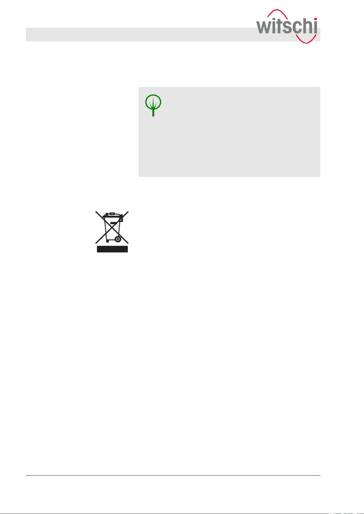
ENVIRONMENT!
Incorrect disposal poses an environmental
hazard!
Incorrect disposal may result in hazards to the
environment.
– Only have authorised specialists dispose of the
–
The device must not be disposed of as household waste, it must
be handed over to a municipal collection point or be disposed of by
a specialist.
.
device.
If in doubt about environmentally sound dis-
posal, contact your local authority or a specialist waste disposal company.
27.02.2018Precision measuring device Watch ...70
Page 71
12 Index
Index
A
Adjusting the screw ........................ 9
B
Beat number ............................ 36
manual entry ......................... 38
manual selection ...................... 38
Bluetooth ...............................34
C
Clamping jaws ............................9
Configuring a touch button
Beat number ......................... 55
Integration time ....................... 55
Lift angle ............................ 55
Connection values ........................19
Connections ............................. 8
Contact data ............................. 3
Contacts ................................ 3
Copyright ............................... 3
Creating a reference watch ................. 36
Customer service ......................... 3
Customising the main display
History .............................. 56
Positions ............................ 56
Result order .......................... 56
W
atch position ........................ 56
Displaying device information
Calibration ........................... 64
Firmware release ...................... 64
Serial number .........................64
Disposal ............................... 70
Dust cover ...........................14, 16
E
Editing a header ......................... 61
Electrical connection ...................... 15
Error messages ..........................68
Escapement ......................... 12, 42
Explanation of symbols .................... 10
I
Integration time .......................... 43
Intended use ............................ 24
Interfaces ............................... 8
K
Keys ................................... 9
L
LED display ..............................6
Lift angle ............................... 39
manual entry ......................... 40
manual selection ...................... 40
Location ............................... 31
D
Delivery ................................29
Diagram
zooming in ........................... 44
zooming out .......................... 44
Dimensions ............................. 19
Display elements .........................10
Display mode
changing ............................ 44
Diagram ............................. 13
VARIO .............................. 13
27.02.2018 Precision measuring device Watch ... 71
M
Maintenance ............................ 65
Malfunctions ............................ 68
Measured results
Diagram ............................. 47
ARIO .............................. 48
V
Measuring procedure
pausing ............................. 50
restarting ............................ 52
resuming ............................ 50
Page 72

Index
Microphone ........................... 9
Assigning functions .................... 58
connecting ........................... 33
Navigation buttons ..................... 58
Misuse ................................ 24
, 14
O
Operating conditions ...................... 20
Order numbers .......................... 17
Overview ................................6
Owner ................................. 27
P
Parameters ............................. 55
Beat number ......................... 36
Integration time ....................... 43
Lift angle ......................... 39, 40
Parts list ............................... 17
Pause ................................. 50
Play ...................................50
Positioning the watch in the clamping area ..... 45
Power supply
Connecting ...........................32
Power supply unit ......................15
Power supply unit ..................... 14, 15
Printer ................................. 33
configuring ........................... 61
connecting ........................... 34
printouts ............................. 51
selection .............................61
Protective cover ......................... 16
R
Rating plate
Power supply unit ......................21
Watch Expert ......................... 20
Rear ................................... 8
S
Scope of delivery .........................14
Screen Saver ........................... 62
Screen symbols ..........................10
Selection list ......................... 38, 55
Service ................................. 3
Settings
exiting .............................. 53
opening ............................. 53
Showing/hiding history .................... 56
Signal amplifier
amplifying ............................49
automatic recognition ................... 49
decreasing ........................... 49
setting manually ....................... 49
Spare parts ............................. 17
Speaker
Switching off ..........................50
Switching on ..........................50
Stand ................................. 17
Storage ................................ 30
Surroundings ............................20
Switching off ............................ 35
Switching on ............................ 34
Symbols
in this manual .........................23
on the power supply unit ................ 25
on the touchscreen .....................10
on the Watch Expert ....................25
System settings
Adjusting brightness ....................62
Calibration ........................... 62
Configuration ......................... 62
Date ................................ 62
Language ............................62
Screen Saver ......................... 62
Time ................................62
T
Taking a screenshot ...................... 51
Technical data ........................... 19
Test mode .............................. 10
Rate ................................ 12
27.02.2018Precision measuring device Watch ...72
Page 73
Index
Special 1 (co-axial) .....................12
Special 2 (AP) ........................ 12
Standard ............................ 12
Thermal printer
Connecting ...........................34
Overview ............................ 33
ouch button ............................ 10
T
Lift angle ............................ 40
Modus (Mode) ........................ 36
Test mode ........................... 42
Touchscreen .......................... 6, 10
Transport ...............................29
Transport inspection ...................... 29
U
Unclean diagram ......................... 49
Use ................................... 24
User interface ........................ 10, 53
W
Warnings ...............................68
Watch Expert
Commissioning ....................... 32
Maintenance ......................... 65
Overview ............................. 6
Storing .............................. 30
Switching off ..........................35
Switching on ..........................34
Watch noise ............................ 50
Weight .................................19
Z
Zoom function ........................... 44
27.02.2018 Precision measuring device Watch ... 73
Page 74

Appendix
Appendix
27.02.2018Precision measuring device Watch ...74
Page 75
A Declaration of conformity
Declaration of conformity
27.02.2018 Precision measuring device Watch ... 75
Page 76
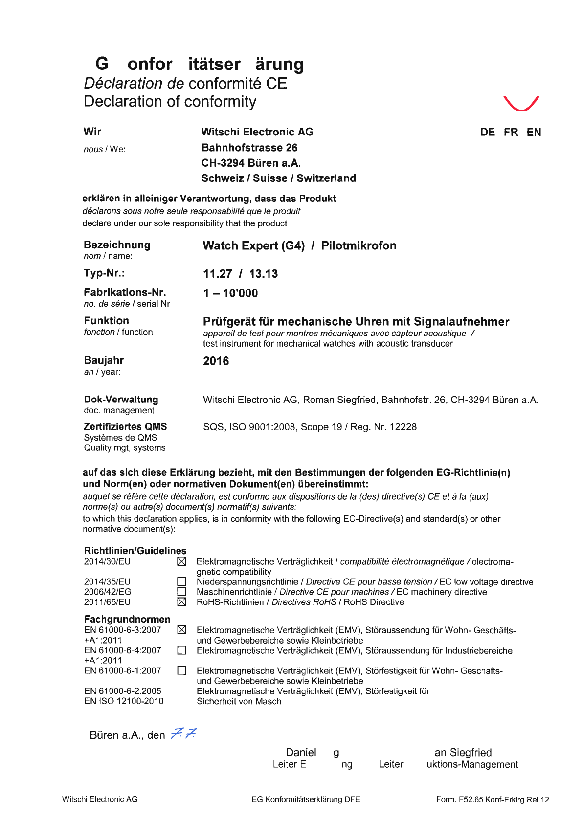
Page 77
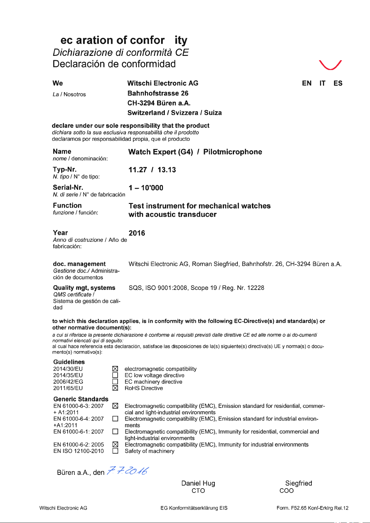
 Loading...