

Page 1
®
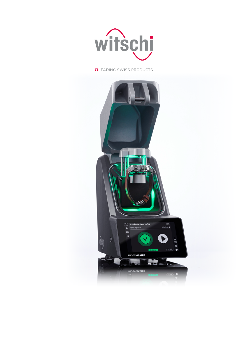
ProofMaster
Operating manual
®
Page 2
Characteristic data
Characteristic data
Document
Change log
Manufacturer
Product
Copyright
Type: Operating manual
Language: English
Version Date Author Description
Version 1.0 17.10.2019 RdT – BRY First edition.
Info
The original text of this manual is written in German.
Translations are made for information purposes only. In cases of doubt,
only the German version shall be decisive.
Witschi Electronic AG
Bahnhofstrasse 26
3294 Büren an der Aare
Switzerland
ProofMaster
Reproduction of this document in whole or in part is not permitted.
Without the prior written consent of Witschi Electronic AG, no section
may be copied, edited or electronically reproduced, transmitted or
recorded on magnetic media or in any other way.
All rights, in particular those of reproduction, distribution and translation
into other languages, as well as those of patent law and patent
application are reserved. The same copyright also applies to the
software supplied with the devices from Witschi Electronic AG.
© Copyright Witschi Electronic AG, 2019 – all rights reserved.
2 / 96 17.10.2019
Page 3

Table of contents
Table of contents
1 General information.............................................................................................................................................. 6
1.1 Technical support.................................................................................................................................................. 6
1.2 Definitions................................................................................................................................................................ 7
1.3 Versions.................................................................................................................................................................... 7
1.4 Guarantee ................................................................................................................................................................ 7
2 Safety ....................................................................................................................................................................... 8
2.1 General pictograms .............................................................................................................................................. 8
2.2 Proper use................................................................................................................................................................ 9
2.3 Safety sign............................................................................................................................................................... 9
2.3.1 Labels on the device......................................................................................................................... 10
2.3.2 Labels on the power supply unit.................................................................................................. 10
2.4 Residual risks.......................................................................................................................................................... 10
2.5 Owner's liability ..................................................................................................................................................... 14
2.6 Personnel qualifications...................................................................................................................................... 15
2.7 Personal protective equipment ........................................................................................................................ 15
2.8 Spare parts.............................................................................................................................................................. 16
2.9 Noise emissions ..................................................................................................................................................... 16
3 Initial operation ..................................................................................................................................................... 17
3.1 Moving the device ................................................................................................................................................. 17
3.2 Transport inspection ............................................................................................................................................ 18
3.3 Storage conditions................................................................................................................................................ 18
3.4 Space requirement................................................................................................................................................ 19
3.5 Requirements regarding the installation site .............................................................................................. 19
3.6 Working area of the operator........................................................................................................................... 20
3.7 List of equipment................................................................................................................................................... 21
3.8 Initial operation ...................................................................................................................................................... 22
3.8.1 Current................................................................................................................................................... 22
3.8.2 Compressed air .................................................................................................................................. 23
3.8.3 Thermal printer................................................................................................................................... 24
3.8.4 Network ................................................................................................................................................ 25
4 Description.............................................................................................................................................................. 26
4.1 Proofmaster............................................................................................................................................................. 26
4.2 Included accessories ............................................................................................................................................ 27
4.3 Required accessories ........................................................................................................................................... 29
17.10.2019 3 / 96
Page 4

Table of contents
4.4 Optional accessories............................................................................................................................................ 30
4.5 Procedure of a tightness test............................................................................................................................ 30
4.6 Definitions................................................................................................................................................................ 31
4.7 Reference to standard ISO22810 .................................................................................................................. 32
5 Use ............................................................................................................................................................................ 33
5.1 Safety during use .................................................................................................................................................. 33
5.2 Basic operation ...................................................................................................................................................... 34
5.2.1 Switching on the Proofmaster ...................................................................................................... 34
5.2.2 Enabling screen saver or standby ............................................................................................... 35
5.2.3 Switching off the device.................................................................................................................. 36
5.2.4 Determining test pressure values................................................................................................ 36
5.2.5 Programming a quick test .............................................................................................................. 38
5.2.6 Selecting the program ..................................................................................................................... 40
5.2.7 Starting the test ................................................................................................................................. 41
5.2.8 Cancelling the test............................................................................................................................. 42
5.2.9 Positioning the watch ...................................................................................................................... 42
5.2.10 Manually lowering/lifting the sensor .......................................................................................... 43
5.2.11 Identifying the tests .......................................................................................................................... 44
5.3 Measured results ................................................................................................................................................... 45
5.3.1 Displaying test results ..................................................................................................................... 45
5.3.2 Selecting the results display.......................................................................................................... 47
5.3.3 Access to results................................................................................................................................ 48
5.3.4 Sorting the results ............................................................................................................................. 49
5.3.5 Deleting measured results ............................................................................................................. 50
5.4 LeakFinder ............................................................................................................................................................... 51
5.5 Programming.......................................................................................................................................................... 55
5.5.1 Menus and operating buttons....................................................................................................... 55
5.5.2 Fixed test programs.......................................................................................................................... 56
5.5.3 Creating a program .......................................................................................................................... 57
5.5.4 Editing a program.............................................................................................................................. 59
5.5.5 Deleting a program........................................................................................................................... 60
5.5.6 Viewing a program ........................................................................................................................... 61
6 Maintenance ........................................................................................................................................................... 62
6.1 Safety during maintenance ............................................................................................................................... 62
6.2 Maintenance schedule......................................................................................................................................... 63
6.3 Cleaning the seal (O ring)................................................................................................................................... 64
6.4 Replacing the seal (O ring)................................................................................................................................. 64
6.5 Replacing the deformation sensor.................................................................................................................. 64
6.6 Software updates ................................................................................................................................................. 65
6.7 Accessories and spare parts............................................................................................................................. 66
7 Settings.................................................................................................................................................................... 67
4 / 96 17.10.2019
Page 5

7.1 Quick settings menu............................................................................................................................................. 67
7.2 Settings..................................................................................................................................................................... 68
7.3 System ...................................................................................................................................................................... 69
7.3.1 Language selection........................................................................................................................... 69
7.3.2 Screen saver........................................................................................................................................ 70
7.3.3 Display and audio settings ............................................................................................................ 71
7.3.4 Date & time.......................................................................................................................................... 72
7.4 Device........................................................................................................................................................................ 74
7.4.1 Opening speed of the bell cover................................................................................................... 74
7.4.2 Sensor lighting.................................................................................................................................... 74
7.4.3 Quiet pressure release..................................................................................................................... 75
7.4.4 Unit of leak rate.................................................................................................................................. 75
7.5 Import/export .......................................................................................................................................................... 76
7.5.1 Importing/exporting settings ......................................................................................................... 76
7.5.2 Importing/exporting programs...................................................................................................... 78
7.5.3 Resetting the device settings ........................................................................................................ 81
7.5.4 Restoring factory settings .............................................................................................................. 82
7.6 Printer........................................................................................................................................................................ 83
7.6.1 Configuring the printer .................................................................................................................... 83
7.6.2 Configuring the label........................................................................................................................ 84
7.7 Network .................................................................................................................................................................... 87
7.8 WiCoTRACE............................................................................................................................................................ 87
7.9 System information .............................................................................................................................................. 88
Table of contents
8 Troubleshooting..................................................................................................................................................... 89
8.1 Error messages ...................................................................................................................................................... 89
8.2 Malfunctions............................................................................................................................................................ 90
8.3 Opening the bell cover in an emergency....................................................................................................... 91
9 Decommissioning and disposal......................................................................................................................... 92
10 Technical data........................................................................................................................................................ 93
17.10.2019 5 / 96
Page 6
General information
1 General information
Purpose of the documentation
Liability
Conformity with standards
and guidelines
This documentation contains the necessary information for the proper
operation of the device.
This allows the user to perform operating or maintenance procedures
efficiently.
For reasons of safety and environmental protection, the service
instructions must be followed. In any case, the documentation should be
consulted.
Witschi Electronic AG assumes no liability for errors or omissions.
The "CE" marking confirms that this product complies with the
European requirements regarding safety, health, environmental and
user protection.
See also the declaration of conformity supplied with the machine.
Proper use
General information
The instructions in this document must be observed, in particular the
safety precautions.
This document has been prepared on the basis of the information
available at the time of its publication.
This manual enables safe and efficient handling of the ProofMaster leak
tightness testing device (referred to in the following as "device" or
"ProofMaster"). The manual is an integral part of the device and must
be kept near the device so that it can be accessed by personnel at all
times.
Personnel must have carefully read through and understood this
manual before starting work. To ensure safe working, the safety
indications, warnings and instructions in this manual must be followed.
In addition, the local health and safety regulations as well as the
general safety rules for operation of the ProofMaster must be observed.
Illustrations contained in this manual are intended for illustration
purposes only and may deviate from the model sold.
1.1 Technical support
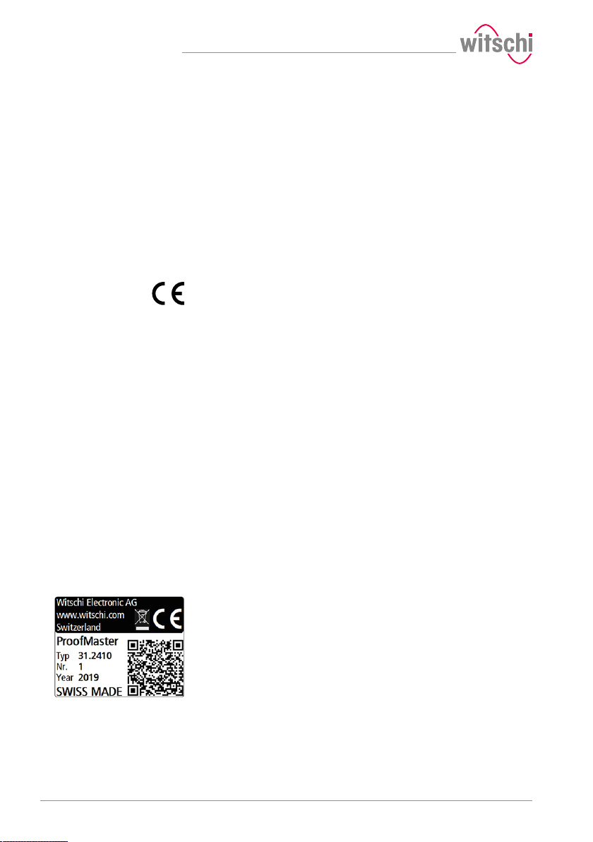
Rating plate
The rating plate of the ProofMaster is located on the reverse of the
device and contains the following information:
• Manufacturer
• Device name
• Type
• Serial number
• Year of manufacture
6 / 96 17.10.2019
Page 7

General information
Technical support inquiries
Customer service
1.2 Definitions
User
Operator
Technical personnel
Device
To request technical support from Witschi Electronic AG, proceed as
follows:
a) Observe the specifications on the machine's rating plate.
b) Try to clearly identify the error that occurred.
c) Contact the customer service of Witschi Electronic AG.
The point of sale can provide you with technical information.
The nearest point of sale can be found on the Witschi Electronic AG
website www.witschi.com.
Witschi Electronic AG would also be pleased to receive information and
feedback, which can be helpful for the improvement of the products.
Information on customer service
Address: Witschi Electronic AG
Bahnhofstrasse 26
3294 Büren an der Aare
Switzerland
Telephone: +41 32 352 05 00
Fax: +41 32 351 32 92
Internet: www.witschi.com
E-mail: [email protected]
The user is the owner of a device which he or she uses as the owner or
which he or she gives to third parties for use.
The operator is the person who carries out production or operating
processes with the device.
Technical personnel are defined as all persons whose training and
qualifications entitle them to carry out installation and maintenance
work on the device. Any work on the electrical and mechanical
components of the device must be carried out by Witschi Electronic AG.
A device is defined as the entirety of the ProofMaster.
1.3 Versions
The ProofMaster is available with the PRO software version. All
functions in this manual refer to the PRO version.
1.4 Guarantee
Witschi Electronic AG grants two years warranty on the new
ProofMaster. Further information can be found in the Warranty
information document supplied with the ProofMaster.
17.10.2019 7 / 96
Page 8
Safety
2 Safety
This section provides an overview of all the important safety aspects
that ensure personal protection and safe and trouble-free operation.
The relevant sections contain additional warnings on the various tasks.
Mandatory
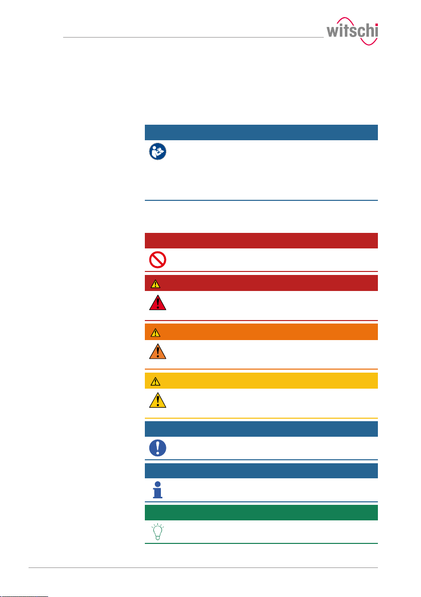
2.1 General pictograms
Prohibition
All safety and protection regulations described here must
be read and observed in order to avoid damage to
equipment, persons and the environment.
The legal regulations, accident prevention and environmental protection
measures as well as the relevant technical regulations for safe working
methods in the country of use and at the place of installation of the
device must also be observed.
Mandatory advice to follow.
DANGER
This combination of symbol and keyword indicates an
imminently hazardous situation that will result in serious
or fatal injury if not avoided.
WARNING
This combination of symbol and keyword indicates a
potentially hazardous situation that can result in serious
or fatal injury if not avoided.
CAUTION
This combination of symbol and keyword indicates a
potentially hazardous situation that can result in minimal
or minor injury if not avoided.
Mandatory
Applicable guideline, measure.
Info
Informative comment.
Tip
Recommendation or advice.
8 / 96 17.10.2019
Page 9
85 mm
30 mm70 mm
2.2 Proper use
2.3 Safety sign
Safety
The "ProofMaster" leak tightness testing device is used exclusively for
testing the water resistance of watches by means of positive and
negative pressure.
The ProofMaster can be used to check the water resistance of both
digital watches and analogue or pocket watches in accordance with the
watch manufacturer's specifications.
You can also use the ProofMaster to build up positive pressure in the
case of a leaky watch to then find the leak by testing it in water.
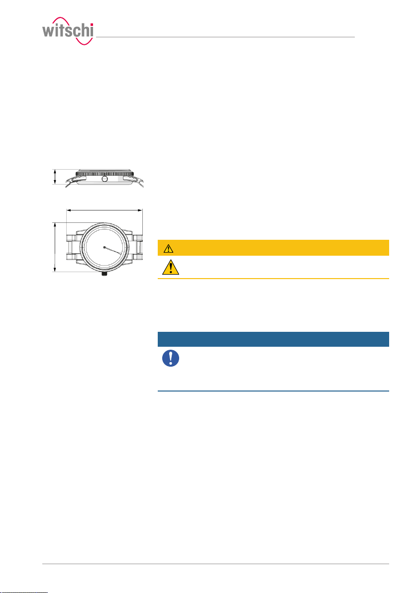
The device is intended for watches with the following maximum
dimensions:
• Diameter: 70 mm
• Thickness: 30 mm
• Width: 85 mm
Proper use also includes observing all the information in the manual.
Any use that deviates from the proper use is considered improper use.
CAUTION
Risk of injury if the device is used improperly!
Improper use of the ProofMaster can result in hazardous situations.
The parts of the device which represent a danger are marked with a
safety label.
Mandatory
Make sure that the safety labels on the device are clearly
legible and clean!
If the labels become dirty or illegible over time, so that hazards can no
longer be identified or service instructions can no longer be followed,
they must be replaced with new ones and affixed to the same place.
17.10.2019 9 / 96
Page 10
Safety
2.3.1 Labels on the device
The stickers listed below are affixed to the ProofMaster.
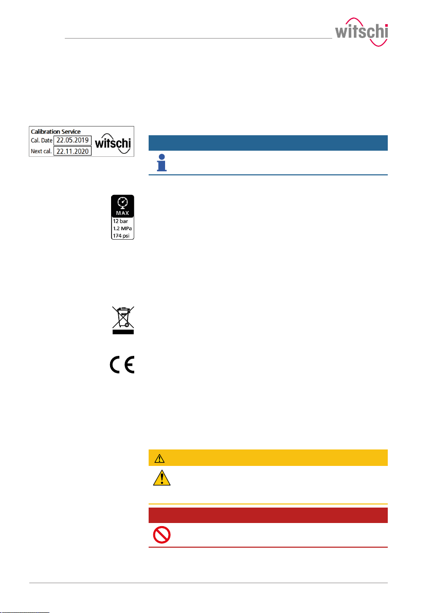
Calibration of the ProofMaster
Maximum supply pressure
The calibration instruction on the underside of the device shows when
the device needs to be recalibrated. For a reliable measurement result,
the specified date for the next calibration must be observed.
Info
The reliability of the measurement results is guaranteed by
regular calibration of the ProofMaster.
This sticker is located next to the connection point of the compressed air
supply. The maximum supply pressure must not exceed 12bar.
2.3.2 Labels on the power supply unit
The labels below are affixed to the power supply unit.
Electrical and electronic
components
The electrical and electronic components in the device contain toxic
substances. The device must therefore be disposed of in a recycling
depot or by a specialised company.
CE conformity
The "CE" marking confirms that this product complies with the
European requirements regarding safety, health, environmental and
user protection.
2.4 Residual risks
Compressed air
10 / 96 17.10.2019
The compressed air devices can be dangerous if they are disconnected
when compressed air is present. A pressurised line that is disconnected
can cause the air to escape extremely quickly as a result of the escaping
pressure, thus posing a danger, especially to the eyes and face.
CAUTION
Risk of injury from compressed air!
If compressed air escapes uncontrolled, there is a risk of injury.
• Take care when working on the compressor or the compressed air
hoses.
Prohibition
Do not exceed the maximum supply pressure of 12bar!
Device components could otherwise burst.
Page 11
Contaminated compressed
air
Prohibition
Never force the device cover to open when the device is
under pressure!
Otherwise parts could be ejected.
Mandatory
Follow the obligations set out below:
Check the compressed air hose before each use!
The integrity of the hose is crucial for safety.
Make sure that the compressed air hose is not subjected to any
external mechanical loads!
The compressed air hose must therefore not come into contact with
sources of heat, oils or greases, and must not be crushed, kinked,
pinched or subjected to excessive tensile loads.
Before the unit is put out of operation, the compressed air supply
must be completely disconnected!
To reduce the risk of damage from residual pressure in the unit.
Mandatory
Observe the documentation of the compressor
manufacturer!
To avoid operating errors that can lead to damage.
Caution - material
Material damage due to the use of contaminated
compressed air!
The use of contaminated compressed air can damage the device.
• Observe the following list of prohibitions and obligations.
Mandatory
Follow the obligations set out below:
Only use oil-free, dry and dust-free air!
Ensures that no condensation water can enter into the device via the
compressed air.
Service the compressor regularly as specified in the manufacturer's
documentation!
Ensures operation with clean compressed air.
Safety
Cracked glass
CAUTION
Risk of injury from cracked glass!
The positive pressure can penetrate into leaking watches during the test.
If this is the case, the interior of the watches will be under pressure after
the test. The glass in the watch can then splinter or crack. It can cause
serious eye injuries and even blindness.
Mandatory
Observe the instructions for wearing safety goggles in this
Operating manual!
If it is necessary to wear safety glasses, make sure that other people in
the room are at an appropriate distance from the device.
17.10.2019 11 / 96
Page 12
Safety
Moving parts
Risk of crushing
Current
CAUTION
Risk of injury from moving parts!
Moving parts inside the device can cause serious injuries including loss
of limbs.
• Observe the following list of prohibitions and obligations.
Prohibition
Never open the device housing manually!
The housing may close again, trapping an object or part of the body.
Mandatory
Return a defective device to the manufacturer
immediately!
To avoid damage of any kind.
CAUTION
Risk of crushing when closing the bell cover!
There is a risk of crushing between the bell cover and the housing of the
device when closing the bell cover.
• Before closing the bell cover, make sure that no body parts or
objects are inside the closing area.
Caution - material
Material damage due to short circuit!
Damage to the insulation on the power cord or the power supply unit
can result in a short circuit and damage the ProofMaster.
Prohibition
Never immerse the device in water!
It is not designed for immersion.
Mandatory
Follow the obligations set out below:
Work on electronic components of the ProofMaster must only be
carried out by customer service!
Failure to do so could void the warranty.
Always disconnect the mains plug before cleaning, maintenance or
repair work!
To avoid electric shock.
To disconnect the power supply unit from the power supply, only pull
on the plug itself, never pull on the cable.
To avoid damage to the cable.
Observe the following recommendations to avoid short circuits:
• If the power cord or power supply unit is damaged, disconnect the
mains plug and have the power supply unit repaired.
• Place the power cord so that it cannot be damaged by external
influences.
• Ensure that access to the power supply is always guaranteed.
• Protect live parts from moisture.
12 / 96 17.10.2019
Page 13
Safety
Opening the housing
Test pressure
Caution - material
Material damage due to opening the housing!
When opening the housing, there is a risk that internal components of
the device or the housing may be damaged.
• Observe the following list of prohibitions and obligations.
Prohibition
Never open the housing yourself!
Opening the housing will void the warranty and Witschi Electronic AG
will not be liable for any accident occurring after the housing has been
opened by an unqualified person.
Mandatory
In the event of malfunctions or problems that cannot be
solved with the help of this manual, contact the
manufacturer!
Failure to do so could void the warranty.
Caution - material
Material damage due to excessive test pressure!
Applying excessive test pressure can damage the watch being tested
and/or the ProofMaster.
• Observe the following list of prohibitions and obligations.
Prohibition
Do not exceed the maximum supply pressure of 12bar!
Device components could otherwise burst.
Mandatory
Follow the obligations set out below:
Make sure that the watch can withstand the pressure!
To avoid damaging the watch.
Only check watches for which a maximum water depth is specified,
without exceeding the limit value!
Observe the following rule: 10m water depth = 1 bar test pressure.
Observe the test pressure values!
See section Determining test pressure values [}Page 36].
Check watches without special information at a maximum pressure of
2bar!
To avoid damaging the watch.
Water ingress
Caution - material
Damage to the watch being tested due to water ingress!
The watch will only remain sealed in the water as long as there is a
positive pressure in the housing, and, if the leak in the watch is too large,
there is a risk of water penetrating the interior of the watch during the
water test.
17.10.2019 13 / 96
Page 14
Safety
Mandatory
Follow the obligations set out below:
Only perform the water test once the "Leak Finder"program has been
executed and the watch can be submerged in water without any risk!
Perform the test in the water immediately after the "Leak Finder"
program has ended!
The watch can only be safely immersed in water for as long as there is
positive pressure in the housing.
Witschi Electronic AG accepts no liability for watches that are
penetrated by water.
If the display is red, remove the watch from the water!
The positive pressure in the watch is too low and water can penetrate.
Touchscreen
2.5 Owner's liability
Caution - material
Material damage due to operating the touchscreen with
sharp objects!
The touchscreen can be damaged if it is operated with sharp objects (for
example with ballpoint pens).
• Operate the touchscreen with the stylus provided for the purpose
or with your fingers.
The device is intended for commercial use. The user is therefore subject
to the statutory obligations of occupational health and safety.
In addition to the safety instructions and warnings in this manual, the
applicable regulations regarding safety, occupational health and safety
and environmental protection for the operation of the device must also
be observed.
The following must be taken into account:
• The user must learn about the applicable occupational health and
safety requirements and identify additional hazards as part of an
assessment of the existing risks, depending on the specific working
conditions at the device's site of operation. The user shall take account
of this assessment to create operating instructions for the use of the
device.
• Throughout the service life of the device, the user must ensure that the
operating instructions which he or she has drawn up comply with
current regulations and, if necessary, adapt them.
• The user must ensure that all persons who use the device have read
and understood these instructions. In addition, the user must also
ensure that personnel are regularly trained and informed of the
hazards.
• The user must provide personnel with the required protective
equipment and ensure that the required protective equipment is worn,
see Personal protective equipment [}Page 15].
• The owner must ensure that the service intervals specified in the
instructions are complied with.
• The owner must ensure that the service intervals for the components
(especially the compressor) are complied with.
14 / 96 17.10.2019
Page 15
2.6 Personnel qualifications
CAUTION
Risk of injury in the event of inadequate personnel
qualifications!
If unqualified personnel carry out work on the device or stay in the
device's danger zone, there is a risk of injury and significant material
damage.
• Observe the following list of prohibitions and obligations.
Mandatory
Follow the obligations set out below:
All activities may only be carried out by qualified personnel!
To avoid operating errors.
The operator of the device must have the appropriate knowledge and
have completed the necessary training for the correct handling of
watches!
In addition, during training, the operator must be informed by the user of
the tasks assigned to him or her and of possible hazards in the event of
improper behaviour. The operator may only carry out tasks that go
beyond the scope of use in normal operation where this is specified
during training and the user has specifically entrusted the operator to do
so.
Unauthorised persons must keep a safe distance from the device!
To avoid unnecessary dangers.
2.7 Personal protective equipment
Personal protective equipment is a device or means worn or held by a
person to protect him or her from one or more risks which could
threaten his or her safety or health.
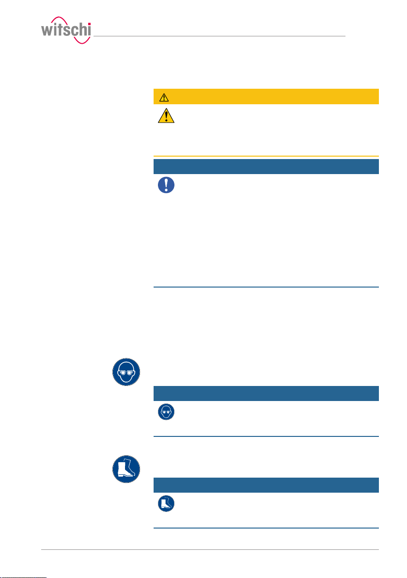
Safety goggles
Safety goggles protect the eyes from flying splinters of glass.
Safety goggles must be worn for the following activities, in particular:
• When removing the watch after a completed test.
• When preparing and carrying out the water test.
Safety
Mandatory
Observe the instructions for wearing safety goggles in this
Operating manual!
If it is necessary to wear safety glasses, make sure that other people in
the room are at an appropriate distance from the device.
Safety shoes
Safety shoes protect the feet from falling objects.
Safety shoes must be worn for the following activities, in particular:
• When accepting theProofMaster.
• When moving the ProofMaster.
Mandatory
Observe the instructions for wearing safety shoes in this
Operating manual!
If it is necessary to wear safety shoes, ensure that other people in the
room also have safety shoes.
17.10.2019 15 / 96
Page 16
Safety
2.8 Spare parts
2.9 Noise emissions
CAUTION
Risk of injury if incorrect spare parts are used!
The use of incorrect or defective spare parts can lead to hazards for
personnel, material damage, malfunctions or even complete failure of
the device.
• If unclear, contact customer service, see Technical support [}Page
7].
Mandatory
Only use original parts from Witschi Electronic AG or parts
approved by Witschi Electronic AG.
To ensure proper operation of the ProofMaster.
Info
For a list of spare parts, see Accessories and spare parts [}
Page 66].
The noise emissions from the ProofMaster are below 80dB and have
been measured according to the guidelines ENISO3740:2001-03 and
ENISO11200:2014-10.
16 / 96 17.10.2019
Page 17
3 Initial operation
3.1 Moving the device
Prohibition
Mandatory
Mandatory
Caution - material
Initial operation
CAUTION
Risk of injury and material damage due to improper
transport!
In the event of improper transport, the device may fall or tip over. This
may cause personal injury or serious damage to property.
• Observe the following list of prohibitions and obligations.
Never transport the ProofMaster when it is connected or
switched on!
Handling may be severely impaired and components of the device may
be damaged.
Follow the obligations set out below:
Always transport the packages vertically and never throw them!
Observe the markings on the packaging!
Do not remove the ProofMaster from its packaging until shortly before
commissioning!
The packaging protects the ProofMaster from external damage.
Always carry the ProofMaster by the carrying handle or with both
hands!
Falling over is prevented.
Only technical personnel are authorised to install the
ProofMaster!
The technical personnel are trained for proper installation.
Risk of material damage in the event of impact!
Avoid impacts when moving the ProofMaster.
17.10.2019 17 / 96
Page 18
Initial operation
3.2 Transport inspection
When accepting the device, check all components and make sure that
no parts have been damaged during transport.
Additionally, check whether the device is complete.
Proceed as follows if there is visible transport-related damage:
a) Refuse delivery.
b) Make a note of the extent of the damage on the transport
company's delivery note.
c) Write a complaint.
Mandatory
3.3 Storage conditions
Store the device and package under the following conditions:
• Storage temperature -20°C to +70°C.
• Relative humidity maximum 80%, no condensation.
• Do not store outdoors.
• Store in a dry and dust-free condition.
• Do not expose to any aggressive media.
• Protect against sunlight.
• Protect against mechanical impact.
• Do not place anything on top of the device packaging.
Report damage or missing parts to Witschi Electronic AG
immediately!
Claims for damages can only be made within the applicable claim
periods.
18 / 96 17.10.2019
Page 19
305 mm
243 mm
370 mm
149 mm
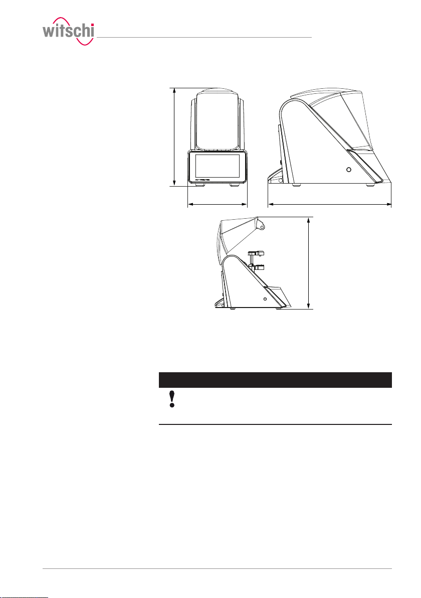
3.4 Space requirement
Initial operation
3.5 Requirements regarding the installation site
The ProofMaster is designed for use on a worktable in as dry and dustfree an environment as possible. The ProofMaster is not suitable for
outdoor use.
Caution - material
The results of the tests may be incorrect in the case of an
unsuitable installation location!
To achieve precise results, the ProofMaster and the test object must be
at room temperature.
The following instructions must be observed for reliable measurements:
• Do not position the ProofMaster and test object in the vicinity of
radiators or open windows.
• Do not expose the ProofMaster or the test object to direct sunlight.
• Use the ProofMaster on an even and horizontal surface.
• The installation site must be vibration-free.
17.10.2019 19 / 96
Page 20
Initial operation
50 cm 50 cm
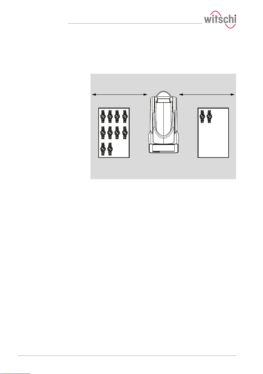
3.6 Working area of the operator
In order for the operator to work comfortably, we recommend leaving at
least 50 cm space on each side of the ProofMaster in order to place the
watch shop there.
20 / 96 17.10.2019
Page 21
1
2
3
4
5
6
8
9
7
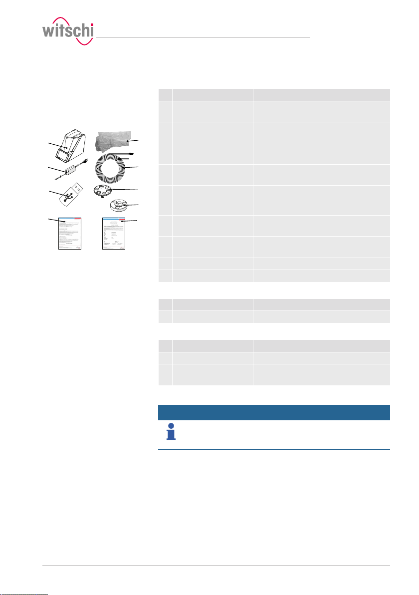
3.7 List of equipment
Initial operation
Equipment included in the
scope of delivery of the
ProofMaster
Additional equipment required for operation of the
ProofMaster
Optional additional equipment
No. Description Function
1 ProofMaster Measurement of the leak tightness of
2 Protective cover Protection of the ProofMaster from dust
3 Compressed air hose Compressed air transfer from the
4 Power supply unit
(12VDC, 3A)
5 USB stick with
WiCoTRACE 3 software
6 Watch underlay Stabilisation of watches < 20mm during the
7 Scratch Protect Lowerable watch support for efficient
8 Warranty information Information about the warranty conditions.
9 Calibration certificate
No. Description Function
1 Compressor Compressed air supply for the ProofMaster.
No. Description Function
1 Thermal printer Print test results without a PC.
2 WiCoTRACE 3 software Recording of test results and management
watches.
deposits.
compressor to the ProofMaster.
Power supply for the ProofMaster.
WiCoTRACE enables simple traceability of
test results and measured values in a
networked database-driven system.
leak tightness test.
protection against unwanted scratches
of programs with a PC.
Info
To order accessories or spare parts, please contact the
points of sale.
Find your nearest point of sale on the website www.witschi.com.
17.10.2019 21 / 96
Page 22
Initial operation
1
2
3
3.8 Initial operation
3.8.1 Current
Required equipment
Connecting
Initial operation of the ProofMaster includes connecting the power and
compressed air supply and making all other connections for smooth
operation (printer, network, etc.).
Caution - material
Risk of material damage if an unsuitable power supply
unit is used!
Using an unsuitable or damaged power supply unit can result in a short
circuit. This may damage the device.
• Only use the power supply unit supplied with the device.
• Position the power cord so that it cannot be damaged by external
influences.
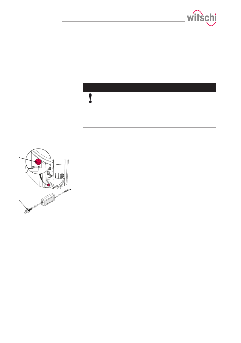
• One ProofMaster
• One power supply unit
a) Make sure that the voltage of the local power supply is suitable for
the power supply unit.
ð 115/230V, 50Hz, 16A.
b) Connect the power supply unit connection 2 to the power supply
connection of the ProofMaster 1.
c) Connect the power supply unit connection 3 to the local power
supply.
ð The power supply is now connected.
Disconnecting
22 / 96 17.10.2019
a) Switch off the ProofMaster.
b) Disconnect the power supply unit connection 3 from the local
mains network.
c) Disconnect the power supply unit connection 2 from the power
supply connection of the ProofMaster 1.
ð The power supply is now disconnected.
Page 23
1
2
3
4
2
4
3.8.2 Compressed air
Recommended compressor
Required equipment
Connecting
Initial operation
CAUTION
Risk of injury due to uncontrolled release of compressed
air!
If compressed air escapes uncontrolled, there is a risk of injury.
• Do not exceed a supply pressure of 12bar.
• Make sure that the compressor is suitable for operation with the
ProofMaster.
• Observe the instructions from the compressor manufacturer.
Mandatory
Read and follow the instructions supplied with the
compressor.
Only qualified persons who are trained in the operation of the
compressor and familiar with the associated instructions may work on
the compressor.
• See section Accessories and spare parts [}Page 66].
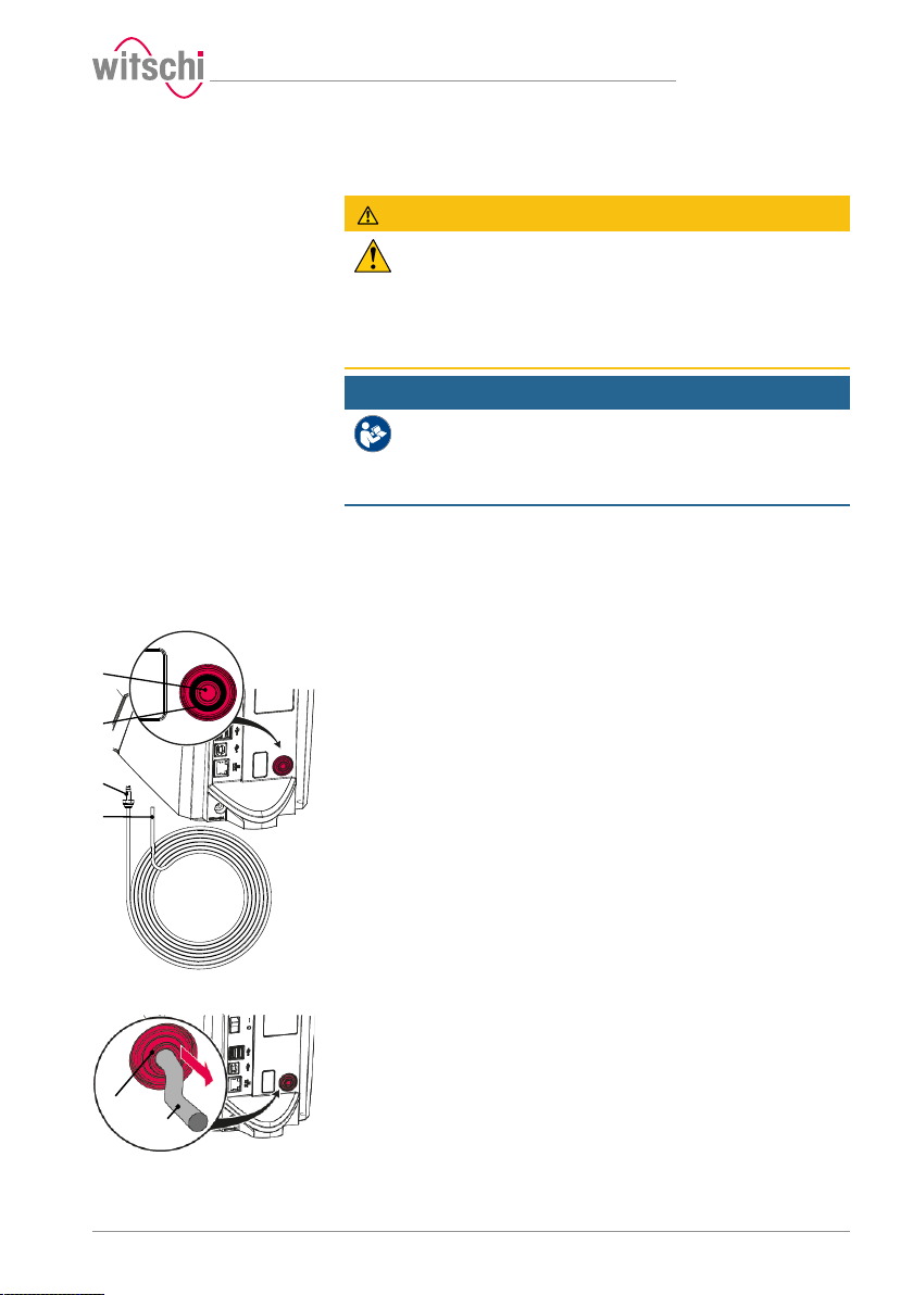
• ProofMaster
• Compressed air hose
• Compressor (not included in the scope of delivery of ProofMaster)
a) Put the compressor into operation as specified in the
manufacturer's instructions.
b) Make sure that the compressor is switched off and the outlet valve
is closed.
c) Connect the coupling of the compressed air hose 3 to the
compressor.
d) Insert the open end of the compressed air hose 4 into the
compressed air plug connection of the ProofMaster 1.
e) Check whether the compressed air hose 4 is properly fastened by
gently pulling it.
f) Open the outlet valve of the compressor.
ð The compressed air supply is now connected.
Disconnecting
17.10.2019 23 / 96
a) Close the outlet valve of the compressor.
b) Drain the air from the hose.
c) Press the ring 2 and pull the compressed air hose 4 out of the
corresponding plug connection 1.
d) Remove the coupling of the compressed air hose 3 from the
compressor.
ð The compressed air supply is now disconnected.
Page 24
Initial operation
1
2
1
2
3.8.3 Thermal printer
Recommended printer
Required equipment
Connection with USB cable
The following steps are only necessary when using a thermal printer.
Info
Read and follow the instructions supplied with the thermal
printer.
• See section Accessories and spare parts [}Page 66].
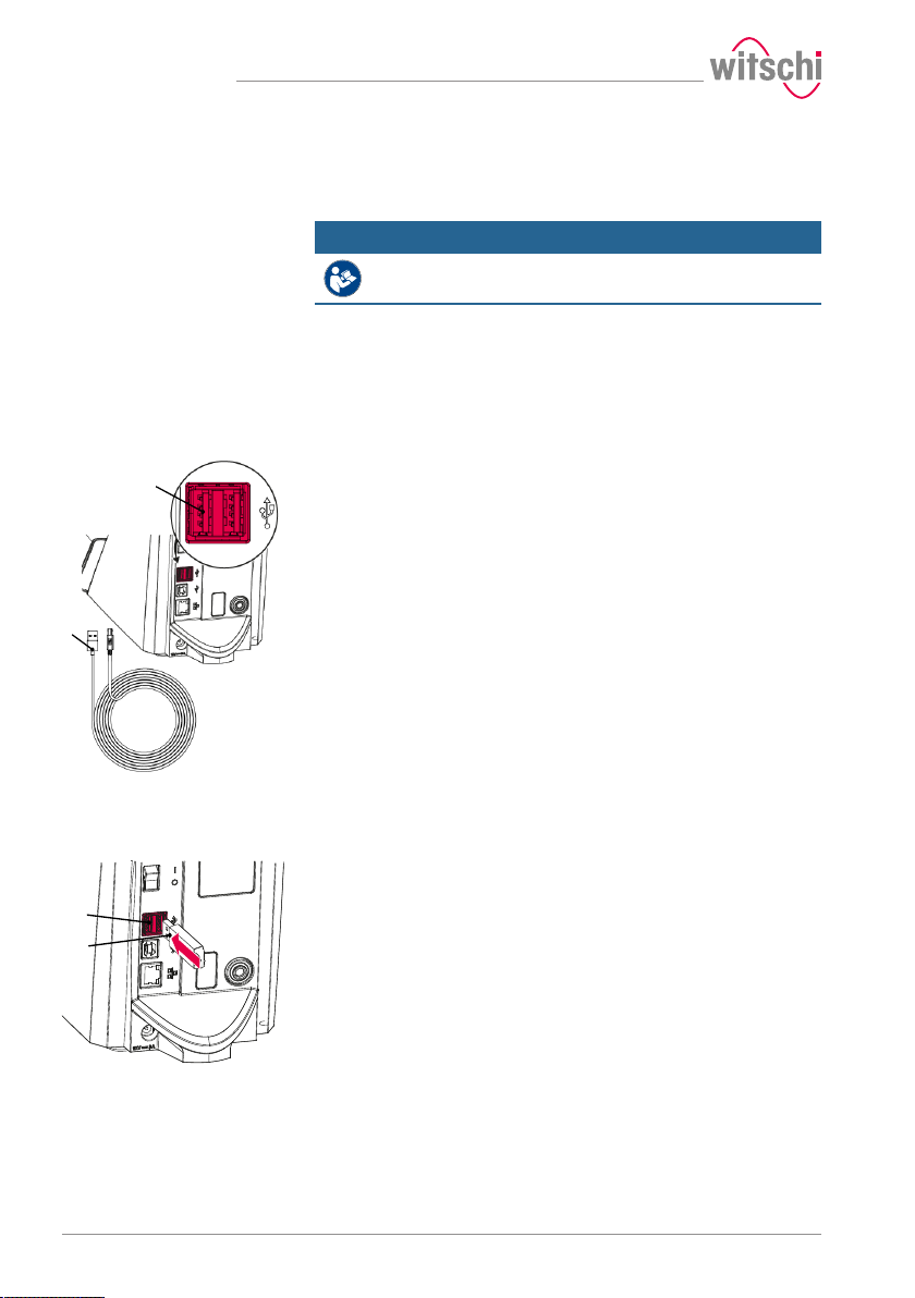
• ProofMaster
• Thermal printer (not included in the scope of delivery of ProofMaster)
• Standard USB cable typeA–B or a Bluetooth set II (not included in the
scope of delivery of the ProofMaster). See Accessories and spare parts
[}Page 66].
a) Put the thermal printer into operation as specified in the
manufacturer's instructions.
b) Ensure that the thermal printer and the ProofMaster are switched
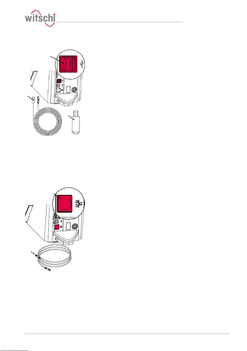
off.
c) Connect the USB cable 2 to the thermal printer USB type B inputs.
d) Connect the USB cable 2 to one of the two USB type A inputs on
the ProofMaster 1.
ð The ProofMaster is now connected to the thermal printer.
e) Switch on the ProofMaster and configure the thermal printer.
ð See Configuring the printer [}Page 83].
Connection via Bluetooth
dongle
24 / 96 17.10.2019
a) Start the thermal printer incl. Bluetooth plug-in unit as specified in
the manufacturer's instructions.
b) Ensure that the thermal printer and the ProofMaster are switched
off.
c) Plug the USB adapter 2 into one of the two USB type A inputs of
the ProofMaster 1.
ð The Bluetooth dongle is automatically recognised by the
ProofMaster.
ð Switch on the ProofMaster and configure the thermal printer.
ð See Configuring the printer [}Page 83].
Page 25
1
2
3
1
2
Initial operation
Disconnecting
3.8.4 Network
Required equipment
Connecting
a) Ensure that the thermal printer and the ProofMaster are switched
off.
b) When connecting using a USB cable, disconnect it from the
thermal printer.
c) Disconnect the USB cable 2 or the Bluetooth dongle 3 from the
ProofMaster 1.
ð The ProofMaster is now no longer connected to the thermal
printer.
ð Configure the ProofMaster again without the thermal printer. See
Configuring the printer [}Page 83].
The following steps are necessary when using a PC within a network.
• ProofMaster
• Ethernet cable (not included in the scope of delivery of ProofMaster)
• PC incl. network environment (not included in the scope of delivery of
ProofMaster)
a) Ensure that the ProofMaster is switched off.
b) Connect the Ethernet cable 2 to the network.
c) Connect the Ethernet cable 2 to the network connection 1 of the
ProofMaster and switch on the ProofMaster.
ð The ProofMaster is now connected to the network.
ð For the configuration of the network, see the Network settings [}
Page 87] section.
Disconnecting
17.10.2019 25 / 96
a) Ensure that the ProofMaster is switched off.
b) Disconnect the Ethernet cable 2 from the network.
c) Disconnect the Ethernet cable 3 from the ProofMaster.
ð The ProofMaster is now no longer connected to the network.
Page 26
Description
1
2
3
4
5
6
1
2
3
4
5
6
1
2
3
4 Description
4.1 Proofmaster
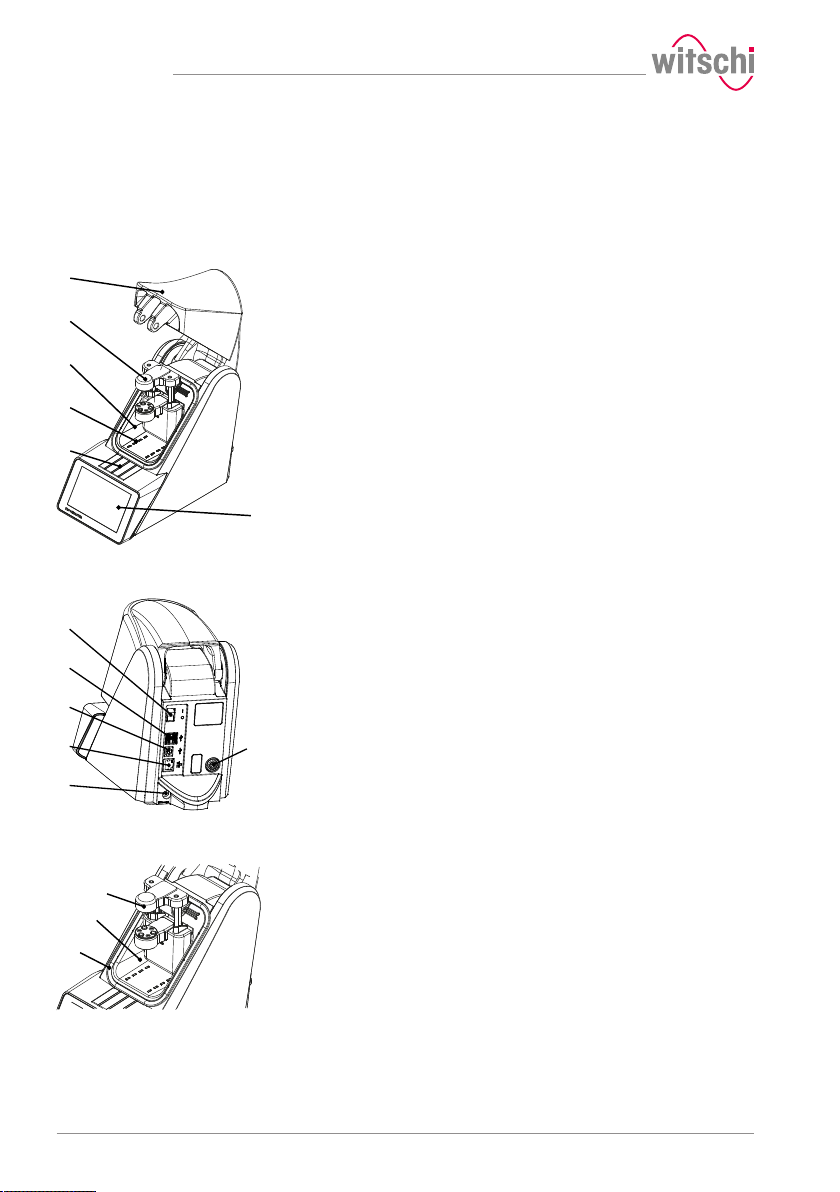
Front view
Rear view
1 Bell cover
2 Deformation sensor
3 Test chamber
4 Compressed air inlet and outlet
5 Flap over catch
6 Touchscreen
The bell cover covers the test chamber. During testing, the bell cover 1
is closed and locked by the catch under flap 5.
The bell cover opens and closes automatically before and after testing a
watch.
1 Main switch
2 2x USB type A ports
3 USB type B port
4 Network connection
5 Electrical connection
6 Compressed air plug connection
Test chamber
26 / 96 17.10.2019
1 Deformation sensor
2 Test chamber
3 Seal (O ring)
The tightness test is performed in the test chamber 2. The deformation
sensor 1 and watch support are located inside the test chamber. When
the test procedure is started, the bell cover closes so that it rests
against the seal 3. This ensures that the test chamber is sealed. The
pressure required for the test can now be built up and maintained in the
test chamber.
The pressure is built up by means of a compressor connected to the
device inside the test chamber 2. The vacuum is generated by a Venturi
valve integrated in the device and the connected compressor.
Page 27
1
2
3
4
6
7
5
1
1
2
3
Description
Deformation sensor
Control and display element
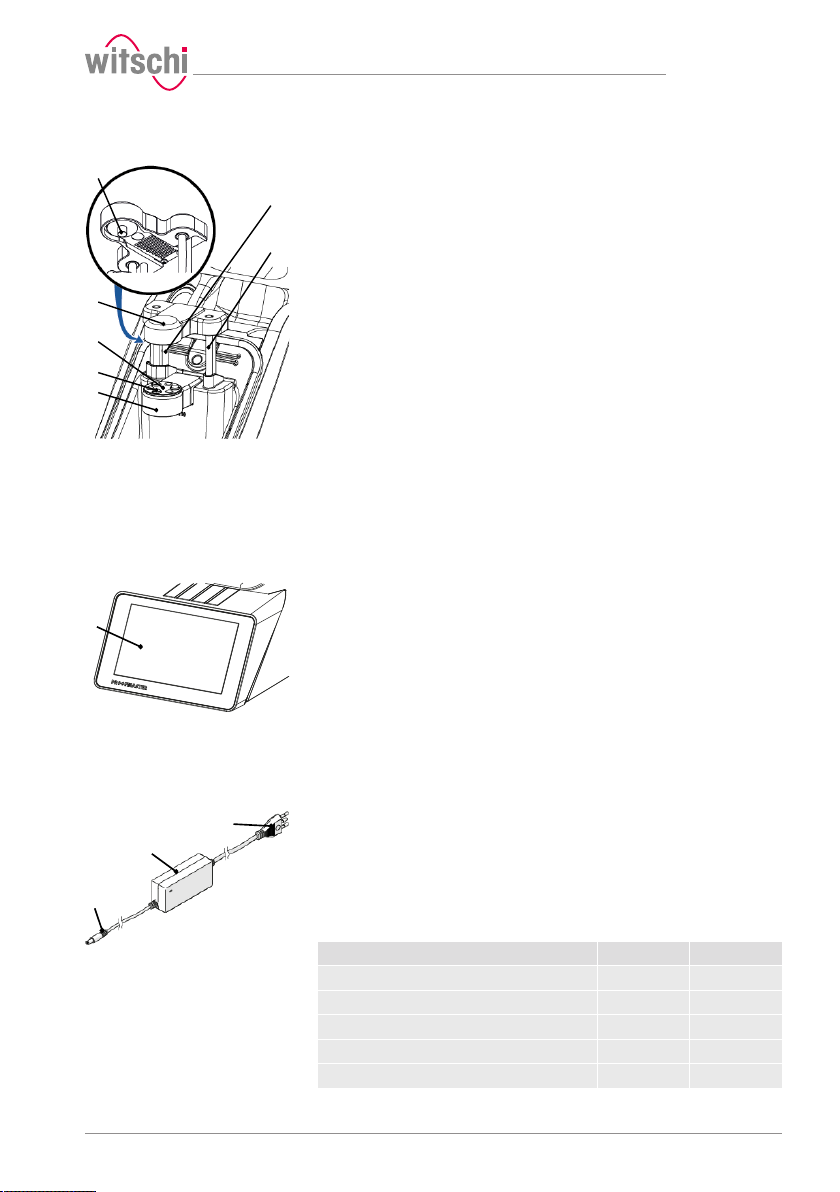
1 Measuring probe
2 Sensor head
3 Scratch Protect
4 Support points
5 Support table
6 Sensor guides
7 Driving rods
The deformation sensor makes it possible to measure the deformation
of the watch. During the test, the watch is stabilised by the three
support points 4 that are integrated in the support table 5. If a small
watch is being tested, the Scratch Protect 3 can be removed and the
watch support can be placed on it. The sensor head 2 with the
measuring probe 1 is located on the watch glass during the test and
can thus measure how strongly the watch housing expands or
contracts.
The sensor head 2 is raised or lowered automatically to the watch by
the drive rods 7 when the bell cover opens or closes.
1 Touchscreen
Using the touchscreen, it is possible to navigate through the menus and
edit the test settings. It also shows the progress and results of the test.
4.2 Included accessories
Power supply unit
17.10.2019 27 / 96
1 Power cable (country-specific)
2 Transformer
3 Electrical connection (device side)
Item no.: JA01-PSD40E120K3
The ProofMaster is connected to the mains via the power supply unit
with the following characteristic data:
Description Unit Value
Input voltage VAC 100 to 240
Input current A 1.0
Input frequency Hz 50 to 60
Output voltage VDC 12
Output current A 3.0
Page 28
Description
1
2
3
1
2
Compressed air hose
Watch underlay
Protective cover
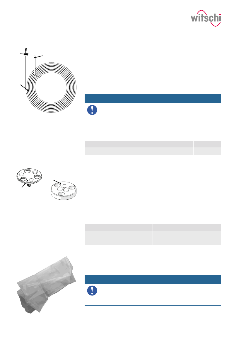
1 ARO 210 plug nipple (compressor side)
2 Open end (device side)
3 Compressed air hose
Item no.: 31.10.311
The compressed air hose is used to supply the ProofMaster with
compressed air. The open end 2 is connected to the compressed air
supply of the ProofMaster and the coupling 3 on the compressor.
Mandatory
The compressor connection must be compatible with the
coupling of the compressed air hose!
• If necessary, replace the coupling supplied with the ProofMaster
with a coupling compatible with the compressor.
The coupling supplied with the ProofMaster has the following
characteristics:
Description Type
Plug nipple ARO 210
1 Scratch Protect
2 Watch support
Item no.: 31.24.702 (watch support) and 31.24.71.40 (Scratch Protect)
The standard support points are suitable for all watches >20 mm. The
Scratch Protect can also be used with these. This scratch protection
only lowers the watch once the sensor head is moved to the support
points. This prevents scratches when placing the watch.
Scratch Protect cannot be used on small watches because the danger
of falling is too great.
Diameter of the watch glass Watch underlay
Ø
<20mm Watch support 1
Glass
Ø
>20mm Scratch Protect 2
Glass
Item no.: 31.24.04.30.001
The dust cover covers the ProofMaster when not in use to protect it
from dust deposits.
Mandatory
When not in use, always cover the ProofMaster with the
corresponding dust cover.
This prevents the test chamber from leaking due to dust and dirt
penetrating between the seal and bell cover.
28 / 96 17.10.2019
Page 29
4.3 Required accessories
Compressor
In order to use the ProofMaster, it must be connected to a compressor.
The compressor must have the following characteristics:
Description Unit Value
ARO 210 coupling - -
Maximum outlet pressure bar 12
Nominal outlet pressure for full operation of
the ProofMaster
Capacity of the compressed air tank litres Min. 4
Compressed air quality - Dry and clean
Tip
Description
bar 11
(air filter)
Witschi Electronic AG has a compressor that is optimally
suited for the. ProofMaster.
JunAir 6–10 compressor 10l, item no. 97.91.103 (230VAC) and
97.91.104 (110VAC).
• For further information, please contact a point of sale.
17.10.2019 29 / 96
Page 30
Description
4.4 Optional accessories
Thermal printer
WiCoTRACE 3 software
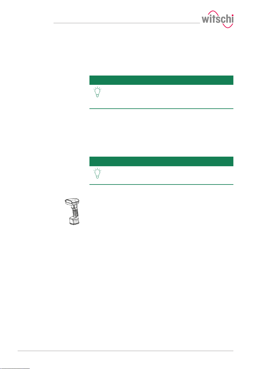
Bar code reader
The test results can be printed out on the thermal printer. The thermal
printer can be connected directly to the ProofMaster via the USB cable
typeA–B or the USB Bluetooth adapter. See Thermal printer [}Page 24].
Tip
With the WiCoTRACE 3 software, any ProofMaster connected to a
network can be synchronised via a PC. In the software, all programs for
the devices are combined and all measurement results from the
connected devices are stored in the WiCoTRACE database. With the
Universal Editor, programs can be created globally and used on any
connected ProofMaster. Connecting to WiCoTRACE, see WiCoTRACE [}
Page 87].
Tip
The bar code reader can be used in conjunction with the WiCoTRACE
software. The software can be used to create bar codes for the various
production orders. When the operator then scans a bar code, the
program and the identification codes are automatically loaded into the
ProofMaster.
Witschi Electronic AG provides the following components:
Thermal printer, item no. JB01-SLK-TE25-S.
Bluetooth adapter, item no. 95.1510.
• For further information, please contact a point of sale.
The WiCoTRACE 3 software can be downloaded free of
charge.
www.witschi.com
4.5 Procedure of a tightness test
A test may consist of several tests
If a test is performed with multiple tests, the following procedure is
repeated.
Determining the initial value
After starting the test, the sensor head is moved into position and the
starting value of the deformation is set to zero.
Build up pressure and record the deformation behaviour of
the watch housing
The test pressure is built up in the test chamber. In order to compensate
for pressure losses caused by the heating of the air, the test pressure is
continuously regulated during the measurement.
30 / 96 17.10.2019
Page 31
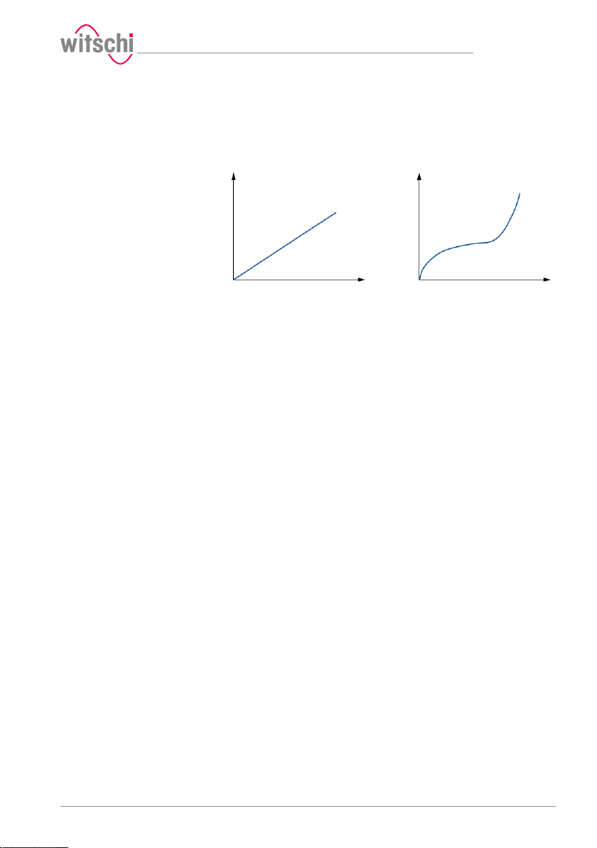
Deformation Deformation
Test pressure Test pressure
Linear deformation behaviour Non-linear deformation
behaviour
The deformation behaviour of the watch is continuously recorded
during pressure build-up and automatically included in the evaluation
algorithm.
Automatic measuring time
The ProofMaster has a new evaluation algorithm which detects elastic
deformation of watches and automatically compensates them.
In the standard setting, the ProofMaster automatically determines the
required measuring time for each measurement. The software continues
the measurement until a meaningful result is obtained.
The measurement time for a simple OK/not OK statement is shorter
than the output of a precise leak rate. It should also be noted that
smaller limits lead to longer measurement times. The maximum time per
test pressure is limited to 300 seconds with automatic measuring time.
For best results in terms of precision and test duration, we recommend
the use of the automatic measurement time.
Description
4.6 Definitions
Deformation measurement
17.10.2019 31 / 96
The measuring method of the ProofMaster is based on the principle of
deformation. The watch is subjected to positive pressure to compress
the watch housing, or a vacuum to expand it. The faster the
deformation is compensated, the larger the leak in the watch case. The
deformation of the case within a certain time serves as the basis for the
measurement to determine whether the watch is leakproof or not.
Leak-tight watch
Under constant pressure, the deformation of the watch housing remains
constant.
Leaky watch
Under constant pressure, the deformation of the watch housing is
reduced.
The difference between the pressure in the test chamber and the
pressure in the watch housing is being compensated at a rate which is
above the limits of the leak rate.
Page 32
Description
Limit
The limit is the maximum permissible leak rate. If the leak rate exceeds
the predefined limit, the watch being tested is classified as non-leaktight.
Relative to the diameter of the watch housing, the following standard
values apply:
Diameter of the watch glass Volume Limit
Ø
<20mm 1000mm
Glass
20mm<Ø
<40mm 2100mm
Glass
40mm<Ø
Glass
Info
The lower the leak tightness limit, the longer the
measurement takes.
This must to be taken into account when planning production.
Leak rate
The ISO 2281 standard specifies the leak rate in µg/min and defines
50µg/min as the limit value for leak tightness at a test pressure of 2
bar. The ProofMaster is configured by default according to these
standard specifications.
To calculate the leak rate, the measuring algorithm needs the exact air
volume in the watch case. The watch sizes suggested in the measuring
program are suitable for a qualitative consideration – we recommend
determining the inner volume of the watch beforehand.
4.7 Reference to standard ISO22810
Leak-tight watch in accordance with standardISO 22810
Relationship between
volume and deformation
Interpretation of ISO 22810
Standard ISO 22810 defines that a watch shall be classified as leaktight if less than 50 µg of air penetrates the watch per minute at a test
pressure of 2 bar.
The ISO 22810 standard does not take into account the volume of the
watch. This means that the leak rate of 50 µg per minute applies to all
watches, regardless of their size.
When testing according to the principle of deformation, the reduction
depends on the free volume in the watch. In a watch with a small
volume, the reduction in deformation is more pronounced with the same
amount of penetrating air. The free volume must be programmed in the
watch for a standard-compliant test.
The standard is based on a pressure of 2bar or 0.5bar. No limit value is
specified for other pressures. It is therefore assumed that the limit of
50 µg per minute applies for all test pressures.
4000mm
3
50µg/min
3
3
32 / 96 17.10.2019
Page 33
5 Use
5.1 Safety during use
Use
Cracked glass
Compressed air
CAUTION
Risk of injury from cracked glass!
The positive pressure can penetrate into leaking watches during the test.
If this is the case, the interior of the watches will be under pressure after
the test. The glass in the watch can then splinter or crack. It can cause
serious eye injuries and even blindness.
Mandatory
Observe the instructions for wearing safety goggles in this
Operating manual!
If it is necessary to wear safety glasses, make sure that other people in
the room are at an appropriate distance from the device.
The compressed air devices can be dangerous if they are disconnected
when compressed air is present. A pressurised line that is disconnected
can cause the air to escape extremely quickly as a result of the escaping
pressure, thus posing a danger, especially to the eyes and face.
CAUTION
Risk of injury from compressed air!
If compressed air escapes uncontrolled, there is a risk of injury.
• Take care when working on the compressor or the compressed air
hoses.
Prohibition
Do not exceed the maximum supply pressure of 12bar!
Device components could otherwise burst.
Prohibition
Never force the device cover to open when the device is
under pressure!
Otherwise parts could be ejected.
Mandatory
Follow the obligations set out below:
Check the compressed air hose before each use!
The integrity of the hose is crucial for safety.
Make sure that the compressed air hose is not subjected to any
external mechanical loads!
The compressed air hose must therefore not come into contact with
sources of heat, oils or greases, and must not be crushed, kinked,
pinched or subjected to excessive tensile loads.
Before the unit is put out of operation, the compressed air supply
must be completely disconnected!
To reduce the risk of damage from residual pressure in the unit.
17.10.2019 33 / 96
Page 34
1
Use
Mandatory
Observe the documentation of the compressor
manufacturer!
To avoid operating errors that can lead to damage.
Contaminated compressed
air
Caution - material
Material damage due to the use of contaminated
compressed air!
The use of contaminated compressed air can damage the device.
• Observe the following list of prohibitions and obligations.
Mandatory
Follow the obligations set out below:
Only use oil-free, dry and dust-free air!
Ensures that no condensation water can enter into the device via the
compressed air.
Service the compressor regularly as specified in the manufacturer's
documentation!
Ensures operation with clean compressed air.
Risk of crushing
5.2 Basic operation
5.2.1 Switching on the Proofmaster
CAUTION
Risk of crushing when closing the bell cover!
There is a risk of crushing between the bell cover and the housing of the
device when closing the bell cover.
• Before closing the bell cover, make sure that no body parts or
objects are inside the closing area.
ü The ProofMaster has been commissioned correctly, see Initial
operation [}Page 22].
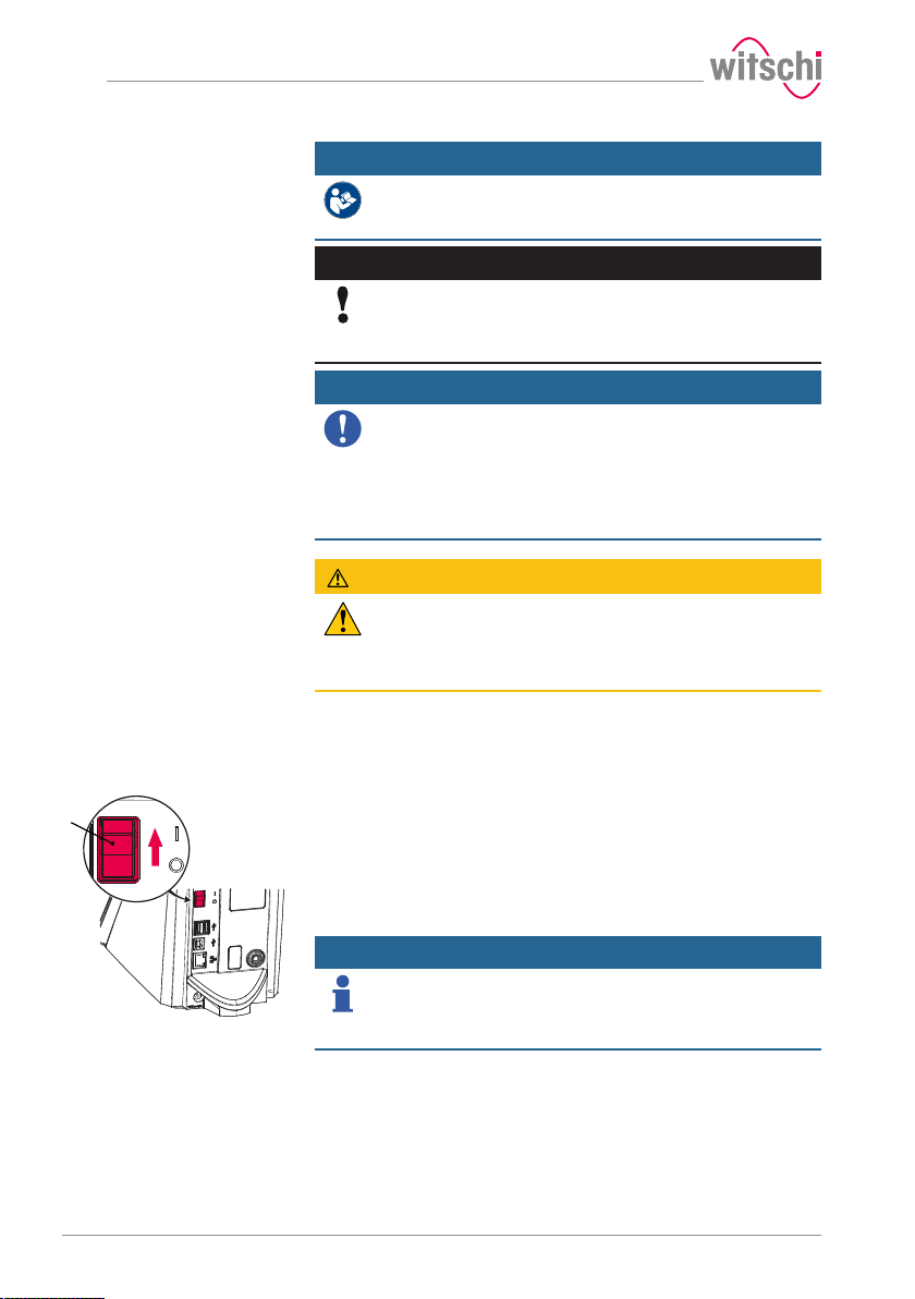
a) Switch on the ProofMaster by pressing the switch 1 in the
direction of the arrow.
ð The home screen appears.
ð The bell cover opens.
Info
When the ProofMaster is switched on for the first time, the
display language can be selected on the displayed screen.
The display language can be changed at any time, see Language
selection [}Page 69].
ð The "Programs" screen appears.
b) Make sure that the pressure reducing valve of the compressor is
set to a maximum of 11bar, but at least 1bar higher than the
desired test pressure.
c) Switch on the compressor as specified in the manufacturer's
documentation.
ð The Proofmaster is ready for operation.
34 / 96 17.10.2019
Page 35
1
b
1
5.2.2 Enabling screen saver or standby
Switching to screen saver
or standby
ü The ProofMaster is switched on, see Switching on the
Proofmaster [}Page 34].
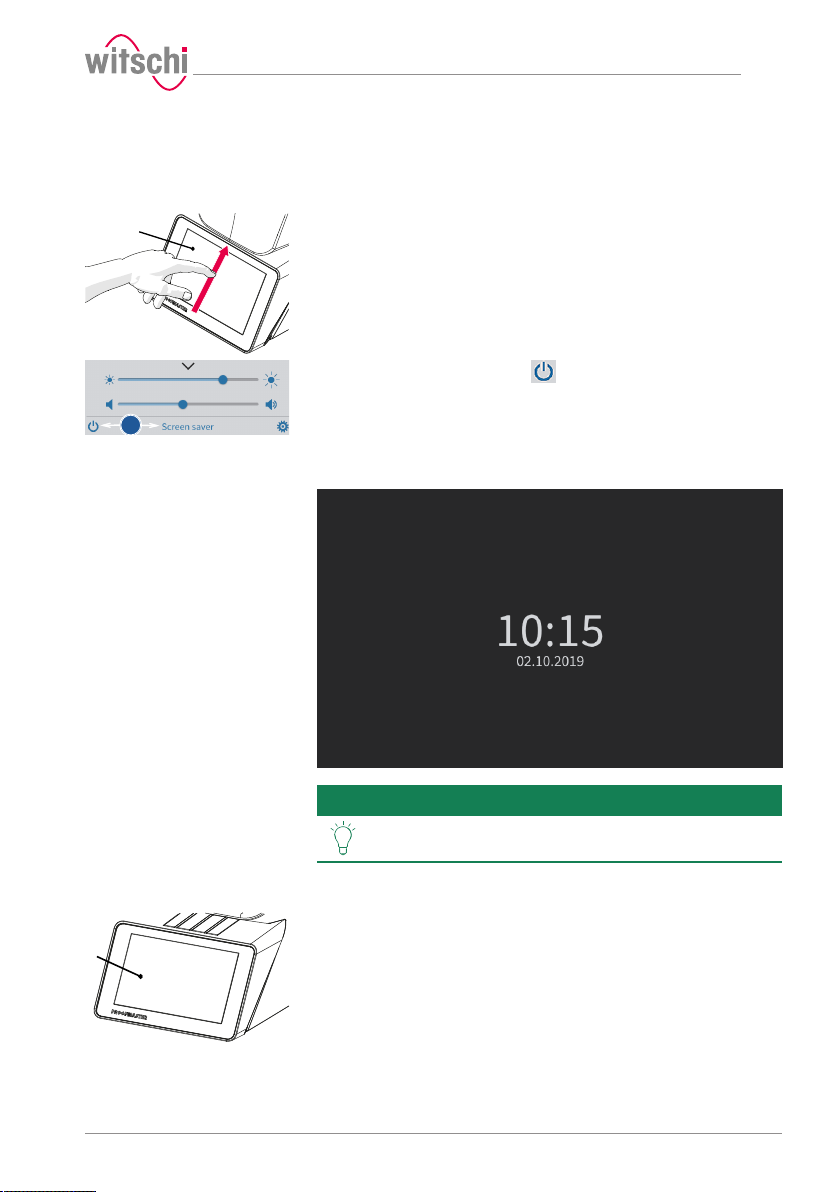
a) Swipe the touchscreen 1 with your finger in the direction of the
arrow.
ð The quick setup menu appears.
b) Press "Screen saver" or tap to switch the ProofMaster to
standby.
ð The bell cover closes and is locked.
ð The ProofMaster is in standby or screen saver mode (standby
screen is always black).
ð The screen saver is displayed (date and time in this example).
Use
Tip
The screen saver is configurable.
See Screen saver [}Page 70].
Exiting screen saver/
ü The ProofMaster is in standby.
standby
a) Touch the touchscreen 1 to exit "Standby" or "Screen saver" mode.
17.10.2019 35 / 96
Page 36
1
Use
ð The bell cover opens.
ð The screen returns to the display that was active before switching
to standby.
5.2.3 Switching off the device
Tip
If the device is not used for a short period of time, enable
standby mode.
See Enabling screen saver or standby [}Page 35].
a) If necessary, remove the watch from the test chamber.
b) Switch off the compressor as specified in the manufacturer's
documentation.
c) Enable the mode, see Enabling screen saver or standby [}
Page 35].
ð The bell cover closes and is locked.
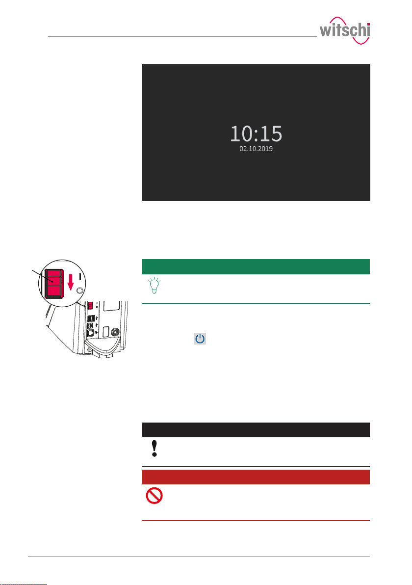
d) Switch off the ProofMaster by pressing the switch 1 in the
direction of the arrow.
e) Cover the ProofMaster with the corresponding dust cover.
5.2.4 Determining test pressure values
Improper test pressure
value settings
36 / 96 17.10.2019
Caution - material
Risk of damaging the watch due to improper test pressure
value settings!
Observe the following list of prohibitions and obligations.
Prohibition
Do not subject jewellery watches or thin watches to a
pressure below -0.3bar!
If jewellery watches or thin watches are subjected to an excessively
strong vacuum, the base or glass of the watch may burst.
Page 37
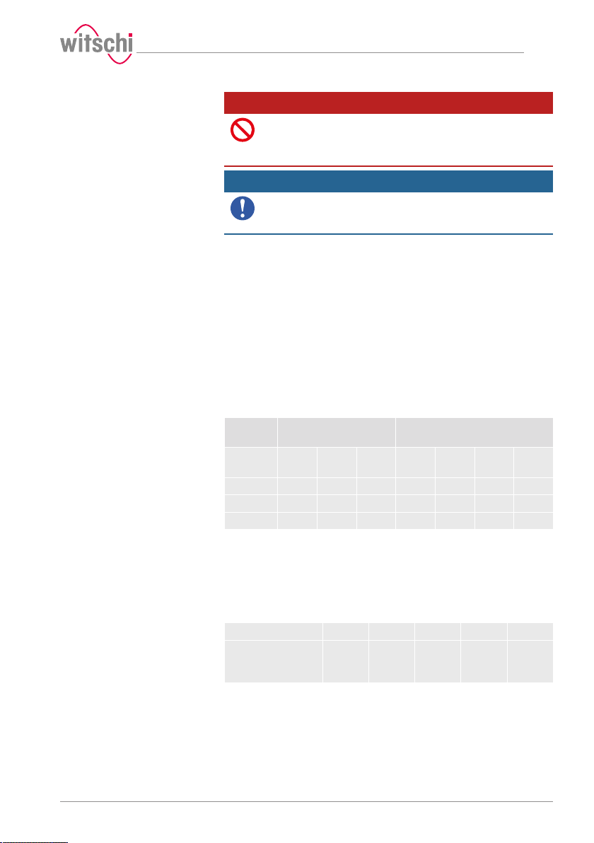
Effect of force on the
watch
Vacuum
Use
Prohibition
Never check a watch with a pressure greater than that
specified in the specifications!
The force exerted may damage the watch and, in the case of flexible
housings, even the movement.
Mandatory
Observe the table for the effect of force on the watch in
order not to apply too high a pressure!
See Effect of force on the watch [}Page 37].
Specifications for test pressure value settings
Observe the following points to achieve optimum results:
• The pressure of the subsequent tests must always be greater than that
of the previous test.
• Perform the vacuum test first. The vacuum test can be used to identify
defects that cannot be detected by an overpressure test:
– Insufficient leak tightness of the housing base.
– Insufficient pressure of the battery cover on the seal.
• Only check watches for which a maximum water depth is specified, and
do not exceed this limit value. Observe the following rule: 10m water
depth=1bar.
• Check wristwatches without special information at a maximum
pressure of 2bar.
Watch
size
(Dia. in
mm)
< 20 5.9N 12.7N 21.6N 31.4N 61.8N 154.0N 307.9N
< 28 11.8N 24.5N 42.4N 60.8N 120.6N 302.0N 604.1N
< 36 19.6N 40.2N 69.6N 100.0N 200.1N 499.2N 998.3N
The ProofMaster can generate a maximum vacuum of 85% compared
to the ambient pressure. The maximum vacuum that can be generated
therefore varies depending on the height at which the ProofMaster is
operated.
The following table shows the maximum vacuum that can be generated
depending on the altitude:
Altitude (m) 0 500 1000 1500 2000
Maximum vacuum
that can be
generated (bar)
Vacuum (bar) Pressure (bar)
-0.2 -0.4 -0.7 1.0 2.0 5.0 10.0
-0.85 -0.81 -0.76 -0.72 -0.68
17.10.2019 37 / 96
Page 38
a
b
e
g
Use
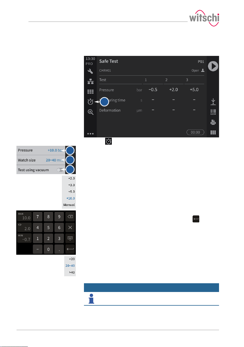
5.2.5 Programming a quick test
Test pressure
ü The ProofMaster shows the home screen.
a) Press .
ð The Quick Select screen appears.
b) Tap Pressure.
ð The selection of the test pressure values appears.
c) Press the desired test pressure or press Manual.
ð The test pressure is programmed or a number field appears
when Manual is selected.
d) For an individual test pressure, enter the desired test pressure
value between -0.7 bar and 10.0 bar and then press to
confirm the entry.
ð The individual test pressure is programmed.
e) Press Watch size to program the size of the watch.
ð The selection of the watch sizes appears.
f) Press the value corresponding to the size of the watch.
g) If necessary, press Vacuum test to perform a vacuum test before
the pressure test.
Info
The pressure for the vacuum test is fixed.
The pressure for the vacuum test is -0.3 bar and cannot be changed.
ð The Vacuum test button is displayed in blue.
38 / 96 17.10.2019
Page 39
1
2
Use
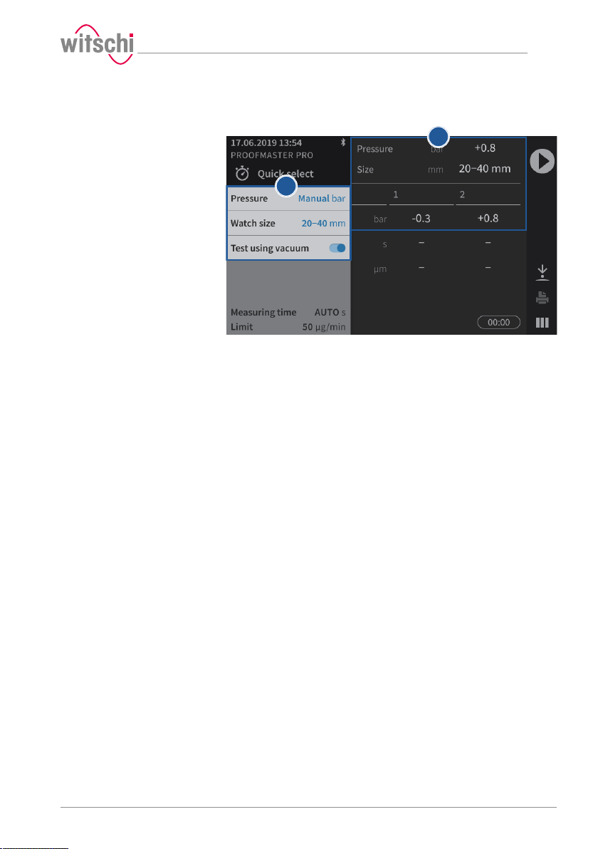
Quick test programmed
The programmed values 1 are displayed 2 and the ProofMaster is ready
for a test.
17.10.2019 39 / 96
Page 40
a
a
Use
5.2.6 Selecting the program
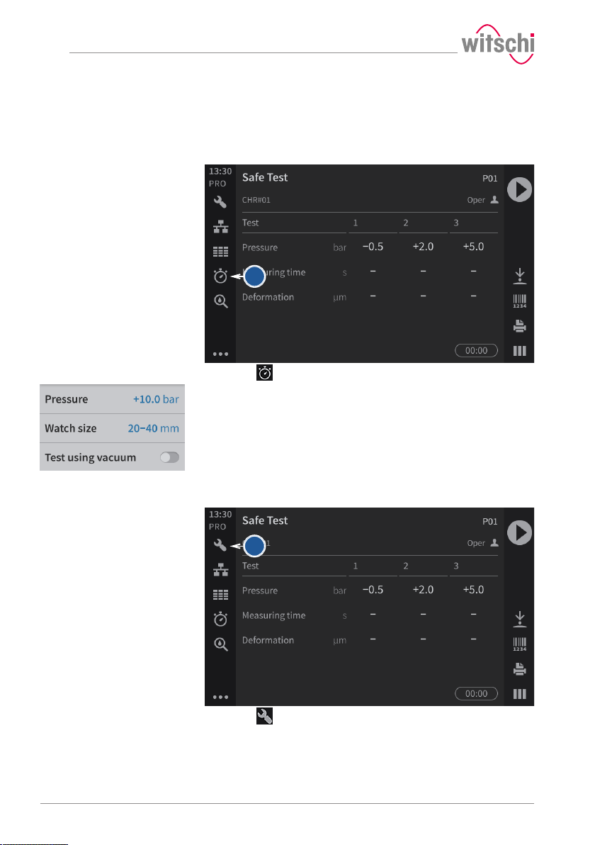
Quick select
The Quick Select is used for single tests or for a single watch.
Essentially, the Quick Select is intended for a watchmaker who, for
example, wants to check a watch before or after a repair.
a) Press .
ð The Quick Select screen appears.
b) Program the test.
ð See Programming a quick test [}Page 38].
Programs
The programs are usually used in production to perform measurements
on a series of identical watches.
a) Press .
ð The program selection screen appears.
40 / 96 17.10.2019
Page 41
b
1
2
5.2.7 Starting the test
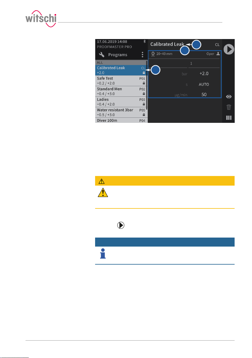
b) Press the desired program in the list.
ð The program is selected and its name1 and parameters2
are displayed.
a) Select the program.
ð See Selecting the program [}Page 40] and/or Programming a
quick test [}Page 38].
CAUTION
Observe all safety regulations for the test pressures in
order to avoid accidents and damage to the watch or the
ProofMaster!
See Safety regulations [}Page 13].
b) Positioning a watch on the support.
ð See Positioning the watch [}Page 42].
c) Press to start the test.
ð The bell cover closes and the test begins.
Info
If one of the test steps fails, the entire test is considered a
failure and is aborted immediately.
The bell cover opens.
d) Follow the test procedure.
ð See Displaying test results [}Page 45].
e) Wait until the bell cover is open.
ð The bell cover opens automatically at the end of the test.
f) Read the test result.
ð See Displaying test results [}Page 45].
Use
17.10.2019 41 / 96
Page 42
1
Use
Prohibition
Do not test a leaky watch twice in a row!
Due to the residual pressure inside the watch, the results would be
distorted.
Open the watch before the second test to allow the positive pressure to
escape.
g) Remove the watch from the ProofMaster.
5.2.8 Cancelling the test
a) Press to stop the test.
ð The test is stopped, the pressure is released and the bell
cover opens.
5.2.9 Positioning the watch
Mandatory
All instructions in this section must be observed!
For the most accurate results possible.
Temperature
Positioning the watch
Mandatory
The watch must be exposed to the same ambient
temperature as the ProofMaster during the test.
Temperature fluctuations in the housing during testing may affect the
test result.
• Keep the watch next to the ProofMaster before testing.
• If the watch has come directly from the user, wait until it has
reached the ambient temperature.
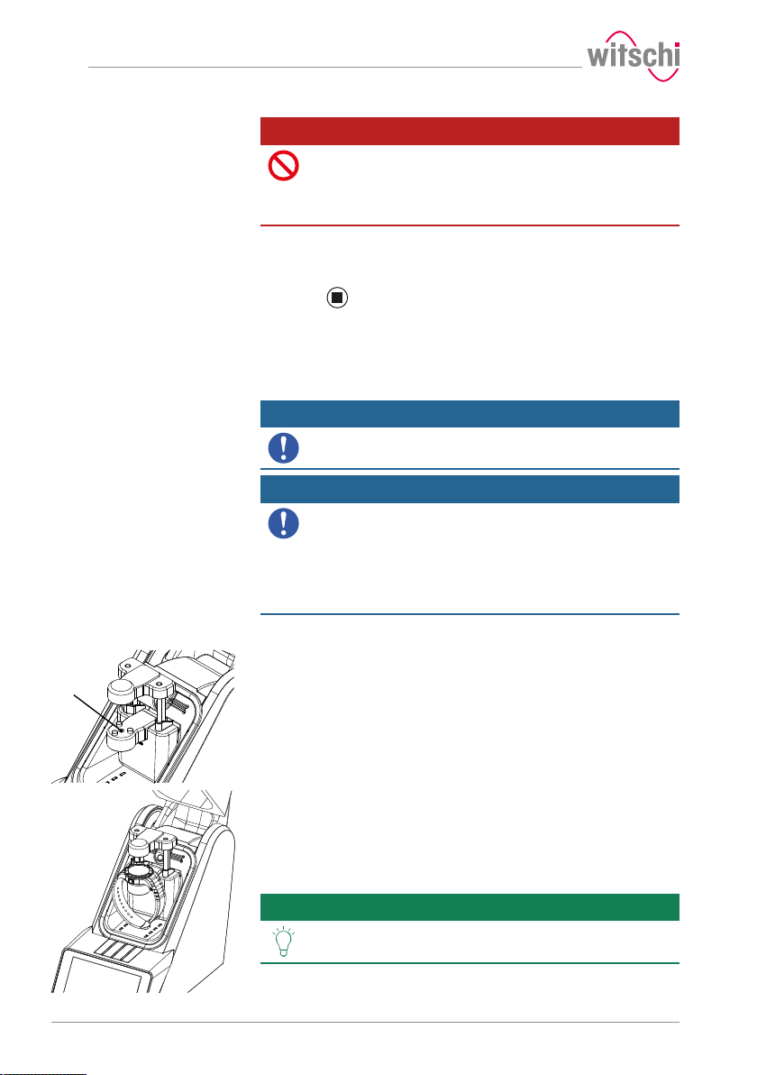
a) Insert the appropriate watch underlay into the opening 1 provided
for this purpose.
ð See Included accessories [}Page 28].
b) Remove the protective sticker or label from the housing.
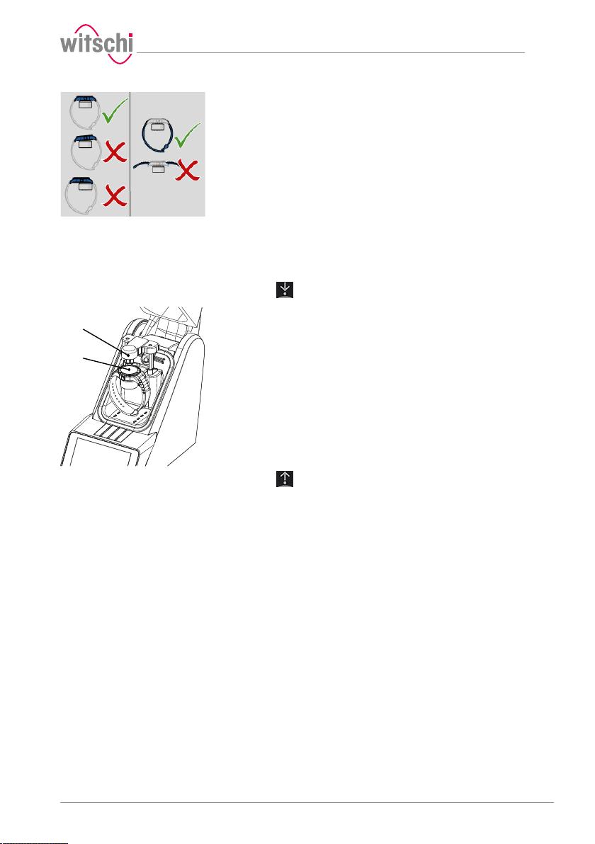
c) Mount the watch on the watch underlay and pay attention to the
following points.
d) If the watch back is not flat, turn the watch over and place the
glass side on the watch underlay.
e) Position the watch so that the measuring probe can be lowered
onto the centre of the watch.
Tip
It is possible to lower and lift the sensor manually.
See Manually lowering/lifting the sensor [}Page 43].
42 / 96 17.10.2019
Page 43
1
2
a) Position the watch strap so that the watch is lying securely on the
watch underlay. If necessary, remove the watch strap.
b) Make sure that the watch strap does not come into contact with
any parts of the device.
ð The watch is positioned horizontally on the three support
points.
5.2.10 Manually lowering/lifting the sensor
Depending on the selected menu, it is possible to lower and lift the
sensor manually.
Lowering the sensor
a) Press to lower the sensor head 1 onto the watch 2.
Use
Lifting the sensor
17.10.2019 43 / 96
a) Press to lift the sensor head 1.
Page 44
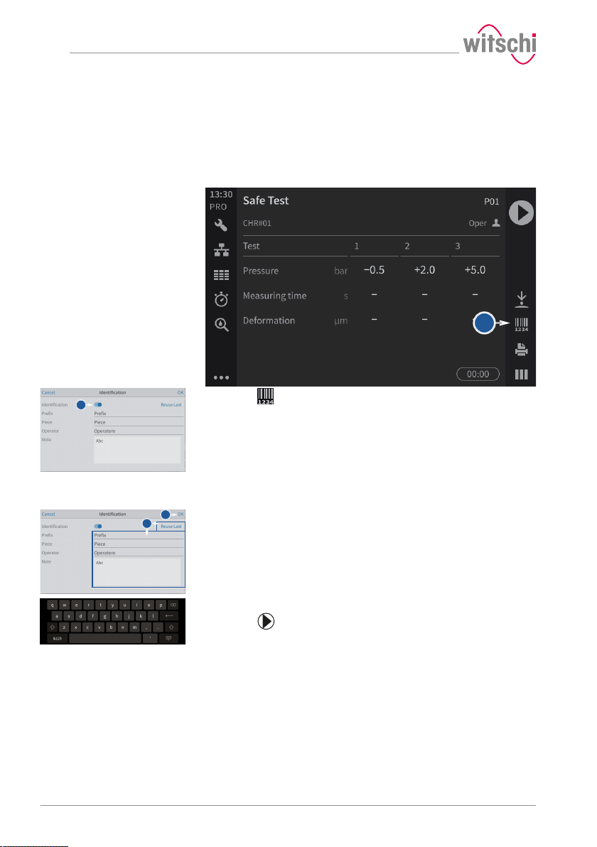
a
1
a
c
Use
5.2.11 Identifying the tests
All measurements are identified by the measured test specimen
(model). It is possible to add further identification elements:
• Prefix (for example, part number)
• User
• Comment (4lines with maximum 32characters)
Enabling identification
a) Press to open the identification window.
b) Enable the identification.
ð The button 1 is blue when the function is enabled and grey
when it is not.
ð The identification parameters entered are saved with the
measurement result and also printed on the label.
Entering the identification
settings
ü The program is selected, Identification is enabled and the
Identification menu is displayed.
a) Press Apply last entries to fill in the input fields with the settings
from the last measurement, or press one of the input fields to open
the alphanumeric keypad.
b) If necessary, enter the desired settings.
ð Use the alphanumeric keypad.
c) Press OK to confirm the entry.
d) Press to perform the measurement.
44 / 96 17.10.2019
Page 45
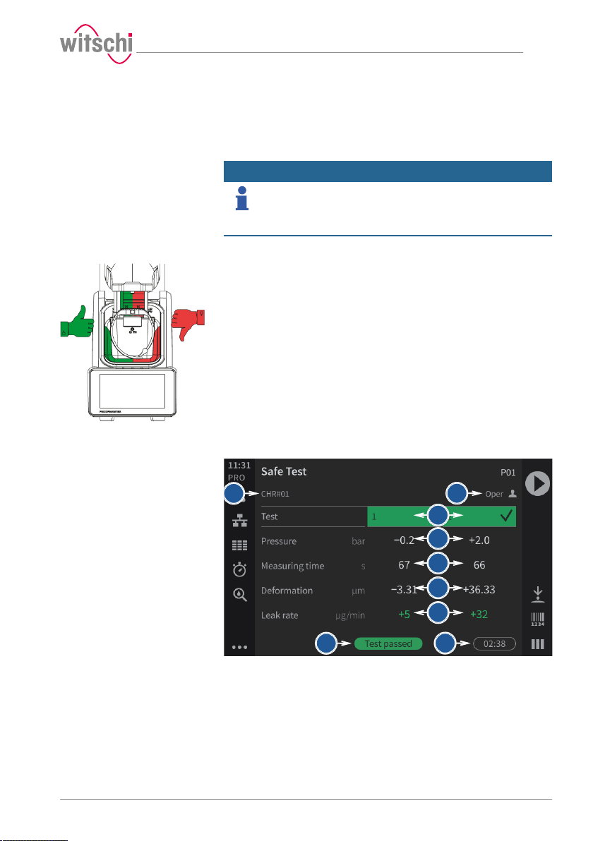
1
2
8
9
6
5
7
4
3
5.3 Measured results
5.3.1 Displaying test results
Info
Test area
When the bell cover is opened after a leak tightness test, the test area
is illuminated green if the test result is good and red if the test result is
bad.
Use
As a result of a leak tightness test, only whether the test is
good or bad is indicated. However, it is also possible to
enable leak rate measurement.
See Creating a program [}Page 57].
Display
Numerical display
Two display types are available for the test result. See Selecting the
results display [}Page 47].
The numeric display provides the following information:
1 Prefix.test specimen
2 Name of the operator (only with enabled identification, in the example
above Opera)
3 Progress and result of each test step
4 Pressure values of each test
5 Measuring times of each test
17.10.2019 45 / 96
Page 46
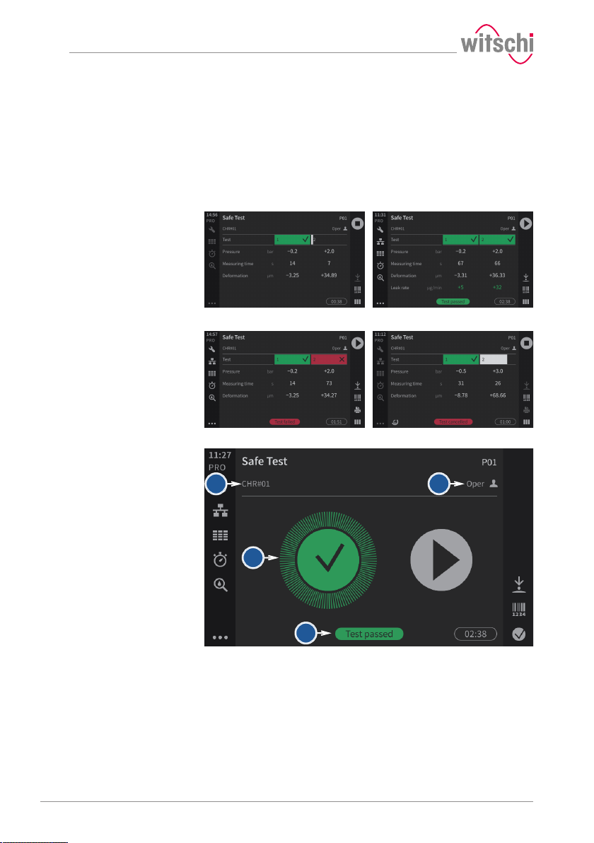
Test running Test OK
Test rejected Test manually aborted
1
2
3
4
Use
6 Measured deformations for each test
7 Leak rate (only in Precise mode)
8 End result of the test
9 Total testing period
The following examples show possible display phases.
Reduced display
The numeric display provides the following information:
1 Prefix.test specimen
2 Name of the operator (only with enabled identification, in the example
above Opera)
3 Progress and result of each step
4 End result of the test
46 / 96 17.10.2019
Page 47
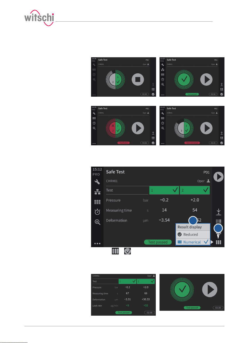
Test running Test OK
Test rejected Test manually aborted
a
b
Numeric Reduced
In the examples below, the first test is running, the second test result is
OK and the third test result is not OK.
5.3.2 Selecting the results display
The results can be displayed in numeric or reduced form.
Use
a) Press or (at the bottom right of the screen) to open the
display selection window. The icon changes according to the
selected display.
17.10.2019 47 / 96
Page 48
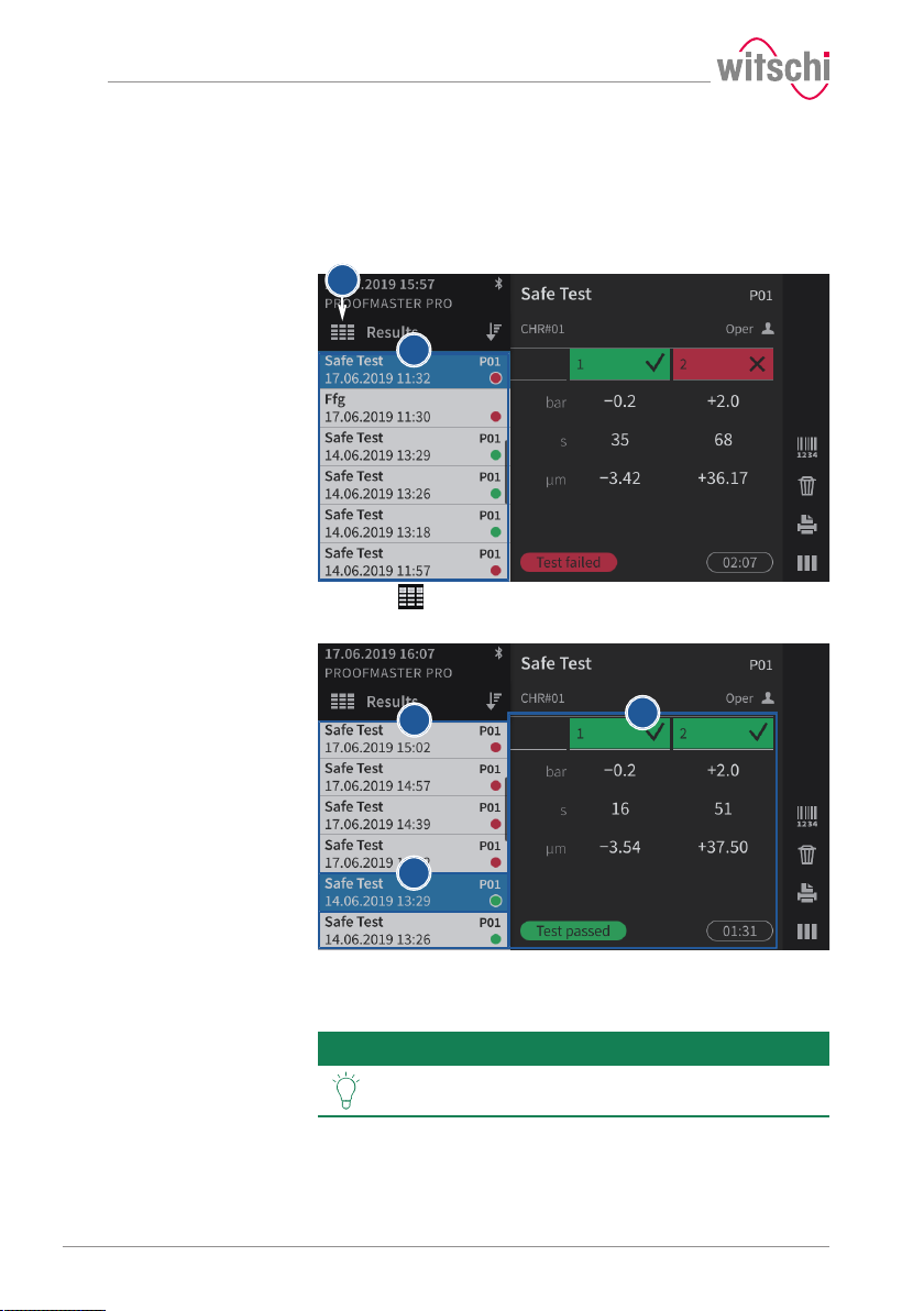
a
1
2
b
3
Use
b) In the Display result window, choose between Reduced or
Numeric.
5.3.3 Access to results
The ProofMaster keeps the last 100 test results in memory.
a) Press to access old results.
ð The window with the results appears 1.
b) Press the desired result in the list.
ð The result selected from the list is highlighted in blue 2 and
Tip
the results of the selected test are displayed 3.
It is possible to sort the measurement results.
See Sorting the results [}Page 49].
48 / 96 17.10.2019
Page 49
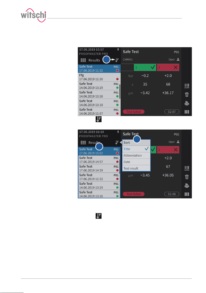
a
b
c
5.3.4 Sorting the results
Use
ü Display in the Results menu.
a) Press to select the sort type.
ð The selection window for the sort type appears.
b) Press the desired sort type in the list (in the above example, Title).
ð The results are sorted according to the selection of the
sorting (in the above example, Title).
c) Press to close the sort type selection window.
17.10.2019 49 / 96
Page 50
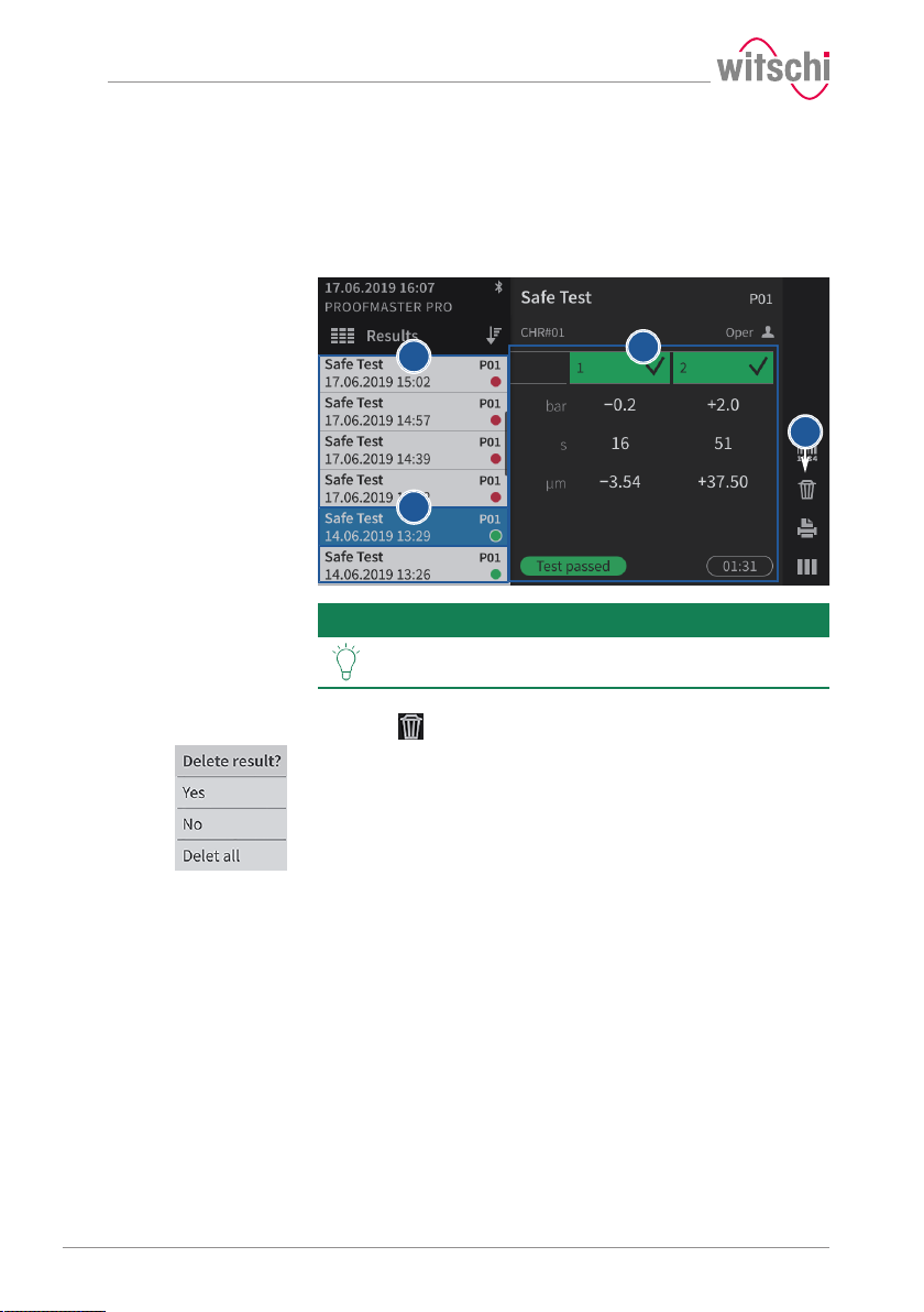
b
a
c
1
Use
5.3.5 Deleting measured results
a) Call up a result that you want to delete.
ð See Access to results [}Page 48].
b) In the list, press the result that is to be deleted.
ð The result selected from the list is highlighted in blue.
Tip
It is possible to sort the measurement results.
See Sorting the results [}Page 49].
ð The results of the selected test are displayed 1.
c) Press to select the deletion type.
ð The selection window for the deletion type appears.
d) Press Yes to delete the selected result, No to cancel the deletion
and Delete all to delete all results of the ProofMaster.
50 / 96 17.10.2019
Page 51
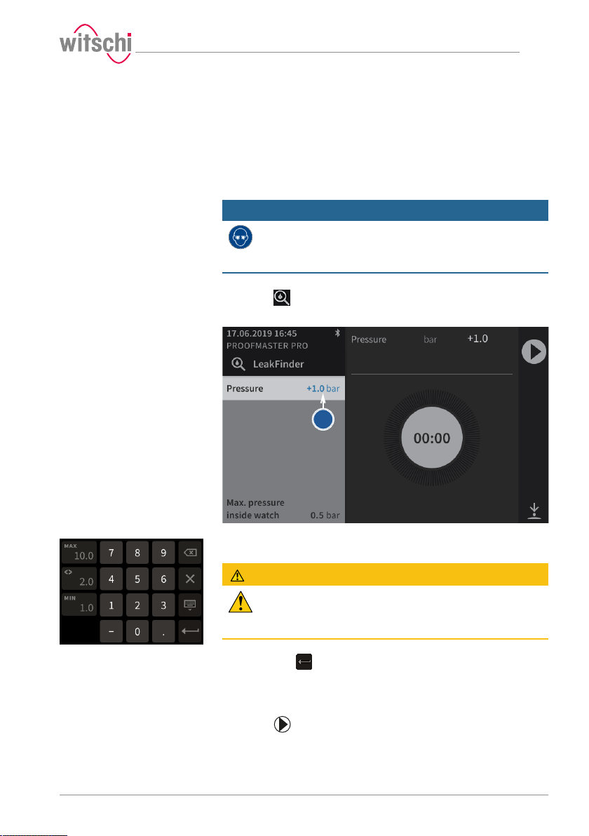
b
5.4 LeakFinder
Pressurising the watch
Use
To locate a leak, the ProofMaster uses the LeakFinder. This program
creates a positive pressure inside the watch case. When the watch is
then placed in a container filled with water, the rising bubbles indicate
the point of leakage.
The LeakFinder program can also be used without a previous leak test.
Mandatory
Wear safety goggles during the entire leak detection
process!
Pressure is applied to the inside of the watch. This can cause the watch
glass to burst.
ü The result of the leak test of a watch was "not OK".
a) Press to enter LeakFinder mode.
ð The LeakFinder window appears.
b) To define the test pressure, press on the pressure value (blue).
ð A number field appears.
CAUTION
Observe all safety regulations for the test pressures in
order to avoid accidents and damage to the watch or the
ProofMaster!
See Safety regulations [}Page 13].
c) Enter the desired test pressure between 1.0bar and 10.0bar and
then press to confirm the entry.
ð The test pressure is programmed.
d) Place the watch you want to test in the ProofMaster.
ð See Positioning the watch [}Page 42].
17.10.2019 51 / 96
e) Press to pressurise the watch..
ð The bell cover closes.
Page 52
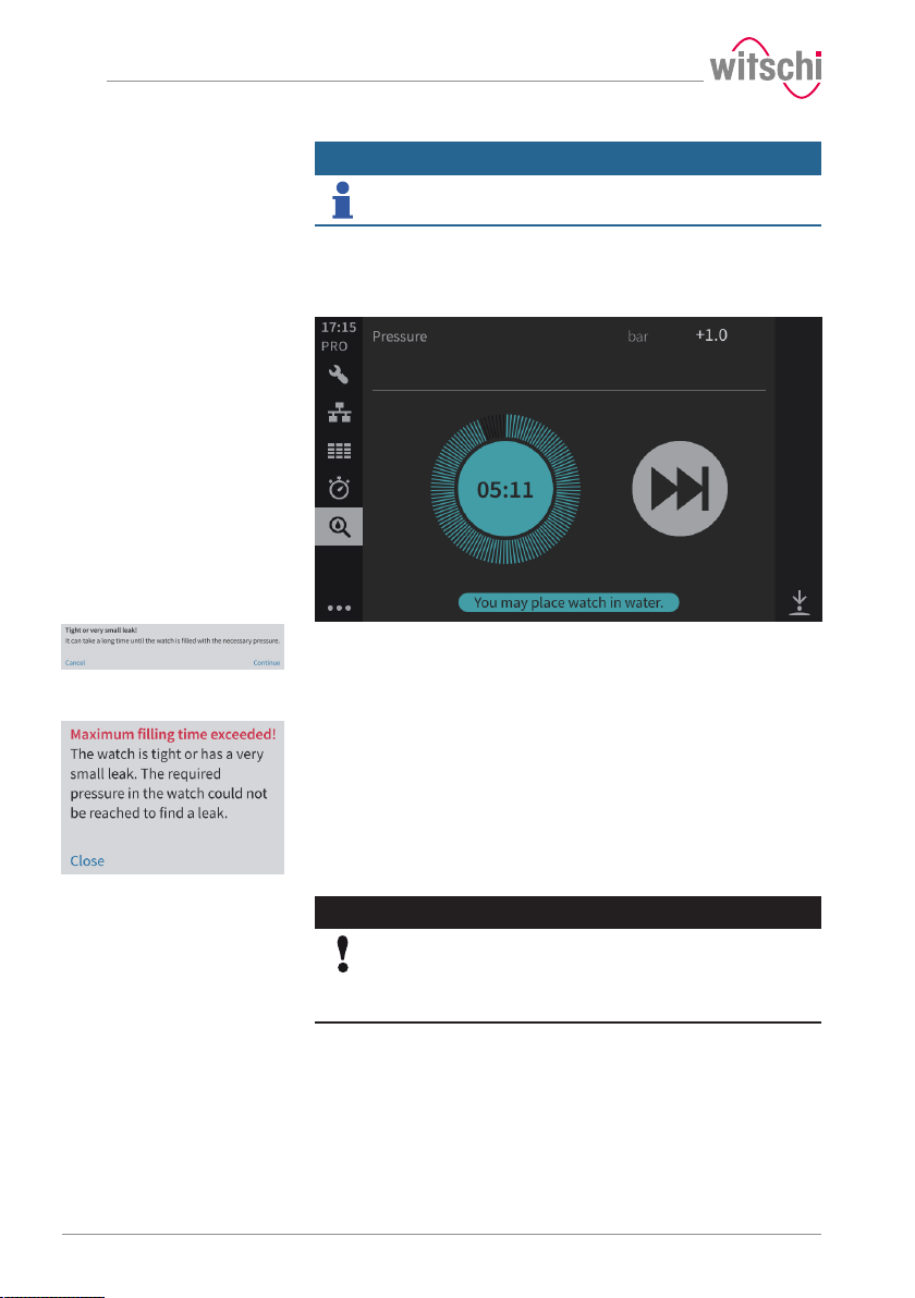
Use
Info
The process can last up to 10minutes.
f) Wait until the bell cover opens.
ð The time shown in blue is the time available to place the
watch in distilled water and search for the leak without the
risk of water penetrating the watch.
ð When this message is displayed, the leak is very small. The
ProofMaster asks whether it should continue with to build up
pressure, which can take a long time, or cancel the process
and resume it at a later time. Press Cancel to cancel pressure
build-up or press Continue to continue.
ð When this message is displayed, the leak is so small that the
watch is considered to be tight or leak detection is not
possible. The ProofMaster releases the pressure from the bell
cover and the bell cover opens.
g) Remove the watch and locate the leak.
Locating the leak
52 / 96 17.10.2019
Caution - material
Damage to the watch being tested due to water ingress!
The watch will only remain sealed in the water as long as there is a
positive pressure in the housing, and, if the leak in the watch is too large,
there is a risk of water penetrating the interior of the watch during the
water test.
Page 53
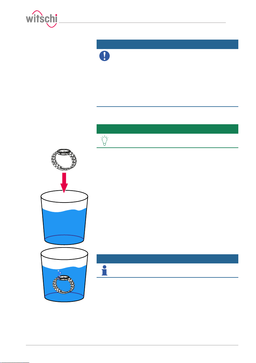
Mandatory
Follow the obligations set out below:
Only perform the water test once the "Leak Finder"program has been
executed and the watch can be submerged in water without any risk!
Perform the test in the water immediately after the "Leak Finder"
program has ended!
The watch can only be safely immersed in water for as long as there is
positive pressure in the housing.
Witschi Electronic AG accepts no liability for watches that are
penetrated by water.
If the display is red, remove the watch from the water!
The positive pressure in the watch is too low and water can penetrate.
ü The watch has been pressurised.
a) Fill a transparent container with water.
Tip
Use distilled water to avoid limescale deposits on the
watch.
b) Place the watch in the container.
Use
c) Observe the formation of bubbles to locate the leak.
Info
If the leak is very small, the formation of bubbles takes a
few minutes.
ð The time shown in blue is the time available to locate the leak
without the risk of water penetrating the watch.
17.10.2019 53 / 96
Page 54
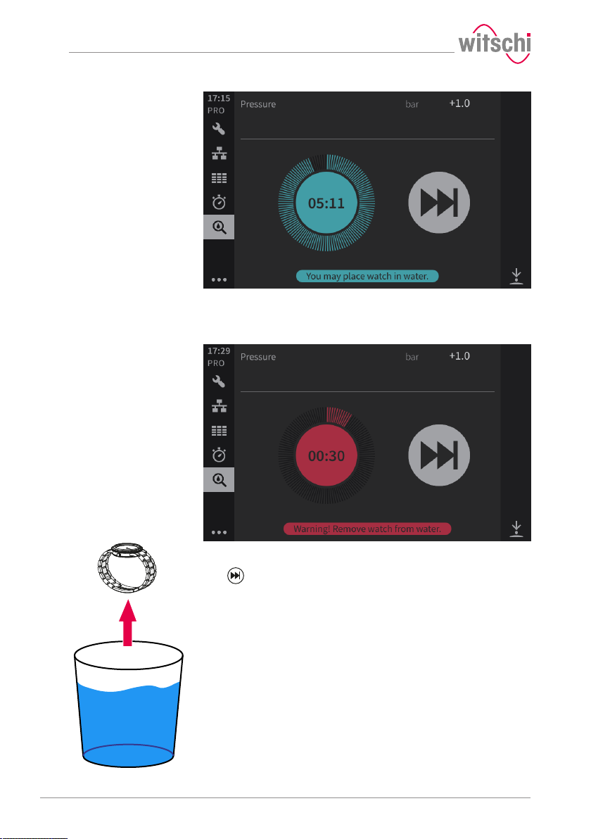
Use
ð When the remaining time is 30seconds or less, the time
display will turn red, indicating that the watch must be
removed from the water to avoid the risk of water
penetrating the watch.
d) Once the leak is located, the number of bubbles decreases or
30seconds remain, remove the watch from the water and press
to end the countdown on the ProofMaster.
54 / 96 17.10.2019
Page 55
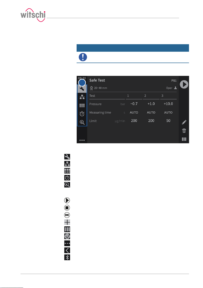
1
5.5 Programming
Mandatory
Programming is always done without running a test
sequence.
5.5.1 Menus and operating buttons
The various function menus can be accessed by pressing the
corresponding button1:
Programs menu
WiCo menu (appears only when WiCoTRACE is enabled)
Measured results menu
Quick Select menu
Leak test menu
Functions of the buttons
Start a test sequence
Use
Stop a test sequence
End the countdown
Create a new user program
17.10.2019 55 / 96
Numerical display
Reduced display
Expand the menus
Reduce the menus
Bluetooth connection
Page 56
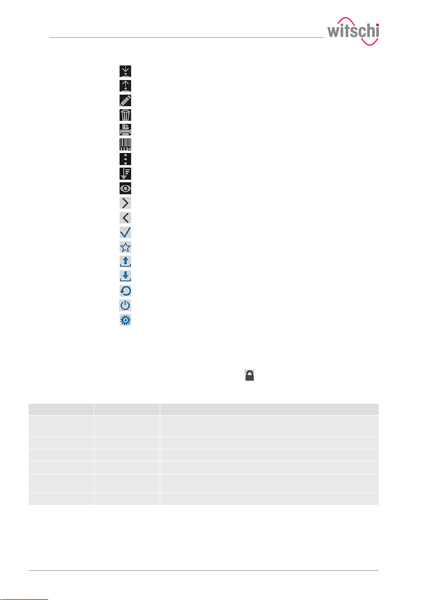
Use
Lower the sensor
Lift the sensor
Edit a program
Delete
Print a label
Identification options
Programs menu options
Sorting options
Display settings of the current program
Select
Back
Selected option
Favourites
Export
Import
Reset
Screen saver
Settings
5.5.2 Fixed test programs
The ProofMaster offers two types of programs:
• Preset programs: Programs predefined by the manufacturer.
These are marked with the symbol.
• Customer programs: Free definition of all parameters.
Each newly created program is therefore a customer program
Abbreviation Program name Info on program
CL Calibrated Leak This program is for checking the ProofMaster using Calibrated Leak.
P01 Safe test Suitable for all watches, except watches with unstable housing.
P02 Standard Men For all types of men's watches (plastic, metal or ceramic housing).
P03 Ladies For ladies' watches.
P04 Jewelery
P05 Diver 100 m For diving watches classified as waterproof to a depth of 100 m.
Parameters for the preset
programs
56 / 96 17.10.2019
This program displays the measured leak rate.
• For jewellery watches.
• For watches with an unstable housing.
Page 57
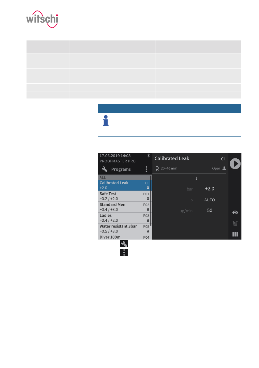
Use
Abbreviation Program name Pressure values
(bar)
CL Calibrated Leak 2.0 50 20–40
P01 Safe test -0.2/2.0 200/200/50 20–40
P02 Standard Men -0.4/3.0 200/50 20–40
P03 Ladies -0.4/2.0 200/50 < 20
P04 Jewelery -0.2/1.0 200/50 < 20
P05 Diver 100 m -0.7/1.0/10.0 200/200/50 20–40
Info
The 50 µg/min limit is only applied at the highest test
pressure of a program, as per ISO 22810. The previous test
pressures are tested for the preliminary test with a limit of
200 µg/min.
Limit values
(µg/min)
5.5.3 Creating a program
Creating a program
Watch size
(mm)
a) Press to display the program menu options.
b) Press to open the program menu options.
17.10.2019 57 / 96
Page 58
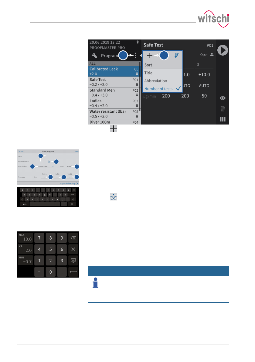
b
c
c
b
1
a
f
e
d
Use
c) Press to create a new program and open the basic
programming window.
Basic programming
a) Give the new program a name and, if necessary, a short name.
ð An alphanumeric keypad appears for entering the names.
b) Press to mark the program as a Favourite.
ð The star is filled in if the option is enabled and empty if the
option is disabled.
c) Select the watch size from the list.
ð The volume used as the basis for the test is displayed 1.
d) Enter the pressure for the first test.
ð A number field appears for the input of the pressure.
e) If necessary, enter the pressure for the second test.
ð A number field appears for the input of the pressure.
f) If necessary, enter the pressure for the third test.
ð A number field appears for the input of the pressure.
Info
To guarantee test results, the pressure of a test must
always be greater than that of the previous test.
58 / 96 17.10.2019
When saving the program, the ProofMaster arranges the test sequence
starting with the test with the lowest pressure value and ending with the
test with the highest pressure value.
g) Press Advanced parameters to enter the advanced programming
screen or Save to save the program.
Page 59
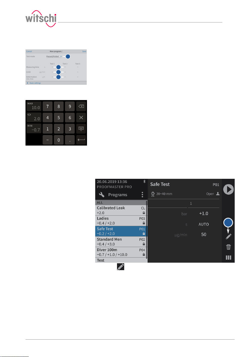
a
b
c
d
b
Use
Advanced programming
5.5.4 Editing a program
a) In test mode, select Precise to enable leak rate measurement.
ð In addition to the result of the leak test (OK or not OK), the
leak rate is displayed.
ð Displaying a leak rate in "Precise" test mode requires more
time for the measurement.
b) If necessary, set a test time for each test.
ð Entering a manually set measuring time may mean that the
measurement algorithm cannot identify enough measuring
points to produce a reliable measurement result. The user
must therefore ensure that the selected measuring time
enables the required test accuracy to be met.
ð A number field appears for entering the times.
c) If necessary, set a maximum leak rate test in µg/min for each test.
ð A number field appears for entering the leak rates.
d) If necessary, set the minimum and maximum deformation limit in
µm for each test.
ð A number field appears for entering the minimum and
maximum deformation.
e) Press Basic settings to enter the basic programming screen or
Save to save the program.
a) Select the user program to be edited.
ð See Selecting the program [}Page 40].
b) Press to display the user program configuration window.
c) Change and save the desired settings.
ð See the Basic programming and Advanced programming
sections of the Creating a program [}Page 57] procedure.
17.10.2019 59 / 96
Page 60
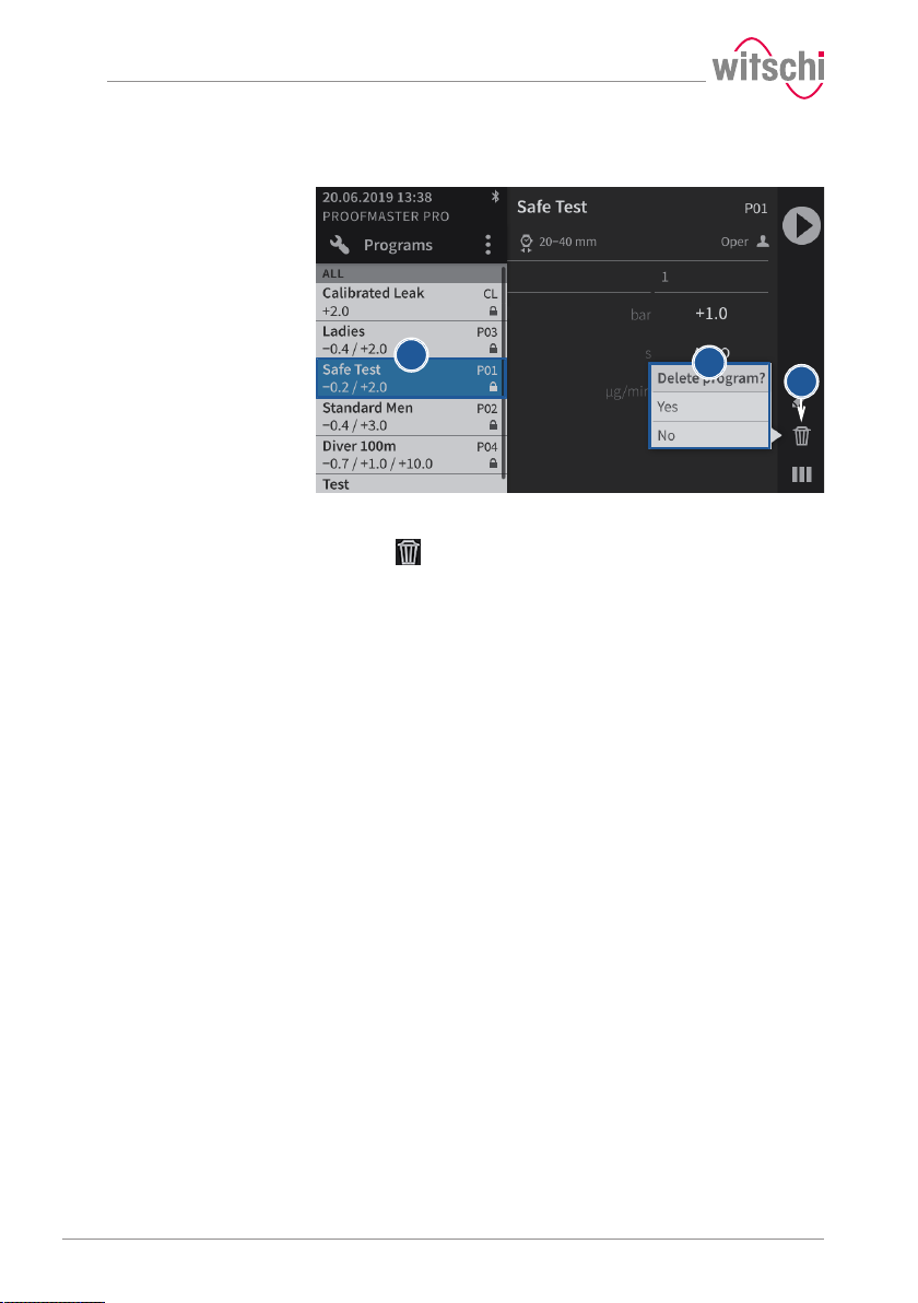
a
b
c
Use
5.5.5 Deleting a program
a) Select the user program to be deleted.
ð See Selecting the program [}Page 40].
b) Press to display the confirmation window for deleting the user
program.
c) Press Yes to delete the selected program and press No to cancel
the operation.
ð The deleted program disappears from the program list of the
ProofMaster.
60 / 96 17.10.2019
Page 61
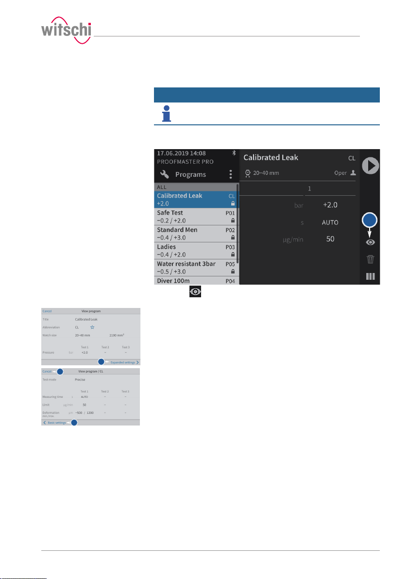
b
c
d
e
5.5.6 Viewing a program
Use
Info
The basic programs cannot be edited.
The settings can only be viewed.
a) Select the basic program.
ð See Selecting the program [}Page 40].
b) Press to display the basic configuration settings of the
program.
c) Press Advanced parameters to display the advanced settings of
the program.
d) Press Basic settings to return to the basic settings of the program.
e) Press Cancel to exit the settings display.
17.10.2019 61 / 96
Page 62
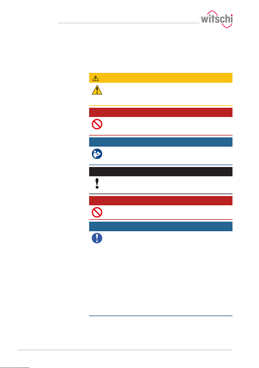
Maintenance
6 Maintenance
6.1 Safety during maintenance
Improper maintenance
Short circuit
CAUTION
Risk of injury from compressed air!
If compressed air escapes uncontrolled, there is a risk of injury.
• Take care when working on the compressor or the compressed air
hoses.
Prohibition
Never force the device cover to open when the device is
under pressure!
Otherwise parts could be ejected.
Mandatory
Observe the documentation of the compressor
manufacturer!
To avoid operating errors that can lead to damage.
Caution - material
Danger of material damage due to short circuit!
Damage to the insulation on the power cord or the power supply unit
can result in a short circuit and damage the ProofMaster.
Prohibition
Never immerse the ProofMaster in water!
This will destroy the device.
Mandatory
Follow the obligations set out below:
Work on electronic components of the ProofMaster must only be
carried outby the customer service of Witschi Electronic AG!
Failure to comply with this requirement will void the warranty.
Place the power cord so that it cannot be damaged by external
influences.
This avoids the risk of damaging the power cord or power supply unit.
If any of the components are damaged, disconnect the mains plug and
have the power supply unit repaired.
Always disconnect the mains plug before cleaning, maintenance or
repair work!
Ensure that access to the power supply is always guaranteed.
To disconnect the power supply unit from the power supply, only pull on
the plug itself, never pull on the cable.
Protect live parts from moisture!
Moisture can cause a short circuit.
62 / 96 17.10.2019
Page 63
Maintenance
6.2 Maintenance schedule
Caution - material
Risk of damage to the ProofMaster due to insufficient
servicing of the compressor!
Failure to service the compressor may result in contamination of the
compressed air by oils harmful to the ProofMaster.
• Service the compressor as specified in the manufacturer's
documentation.
• Make sure to comply with the maintenance cycles specified in the
following maintenance schedule.
ð Non-compliance will void the warranty.
Info
The following maintenance schedule is intended for the
operator of the ProofMaster.
Maintenance of the ProofMaster does not require a specialist technician.
Interval Maintenance task Personnel
Daily Clean the seal with a dry microfibre cloth. Operator
Check that the compressed air hose is secure and in good condition.
Make sure that the bell cover is closed at the end of the day. See
Switching off the device [}Page 36].
Calibration as per the
calibration
instructions on the
device
After 200,000tests or
every 8 years, at the
latest
Have the ProofMaster recalibrated. To do so, contact the point of
sale. See Technical support [}Page 7].
The deformation sensor can be sent individually or installed with the
ProofMaster. See Replacing the deformation sensor [}Page 64].
An inspection must be carried out on the ProofMaster. The message
"Inspection required. Call Witschi service" appears when starting the
ProofMaster. To do so, contact the point of sale. See Technical
support [}Page 7].
Comment
The number of tests since initial commissioning can be found in the
menu Settings > Info > Operating information.
Customer service
Customer service
17.10.2019 63 / 96
Page 64
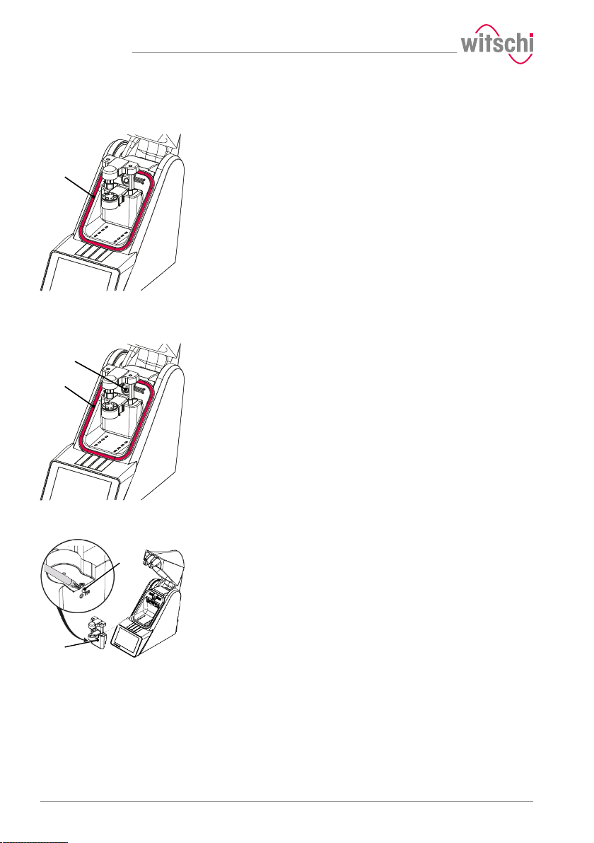
Maintenance
1
2
1
2
1
6.3 Cleaning the seal (O ring)
ü The ProofMaster is switched off and the bell cover is open.
a) Clean the seal 1 with a microfibre cloth.
6.4 Replacing the seal (O ring)
ü The ProofMaster is switched off and the bell cover is open.
a) Lift the seal 2 with the push button 1 and remove by hand.
b) Remove dust particles and other deposits from the seal groove 2.
c) Insert a new seal 2.
6.5 Replacing the deformation sensor
ü The ProofMaster is switched off and the bell cover is open.
a) Unscrew screw 1 with a T10 Torx screwdriver.
b) Remove the deformation sensor 2.
c) Hook in the new deformation sensor 2.
d) Tighten screw 1.
64 / 96 17.10.2019
Page 65
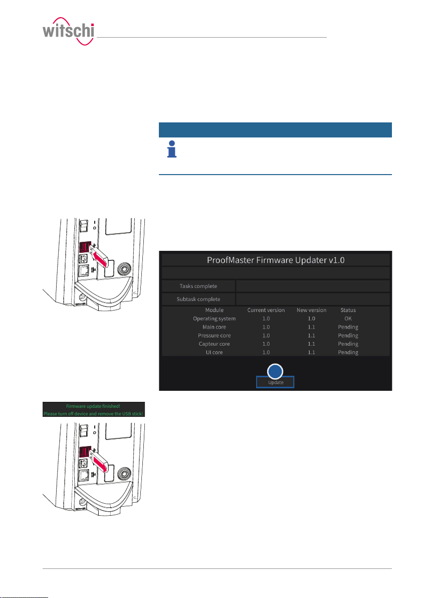
e
6.6 Software updates
With the further development of the ProofMaster, the software may
also be improved under certain circumstances. In certain cases, Witschi
Electronic AG may offer a new version of the software to be installed.
Info
The software for the ProofMaster can be installed as follows:
ü The ProofMaster is switched off.
a) If necessary, unzip the update files for ProofMaster.
b) Save the unzipped files on a USB stick.
c) Insert the USB stick with the update files for the ProofMaster.
d) Switch on the ProofMaster.
Maintenance
Information on how to download the updates can be found
on our website at www.witschi.com.
When you register your ProofMaster on our website, we will personally
notify you of important updates.
ð See Switching on the Proofmaster [}Page 34].
e) Press Update.
f) Wait until the screen with the following messages appears.
g) Switch off the ProofMaster.
h) Remove the USB stick.
ð The ProofMaster update has been installed successfully.
17.10.2019 65 / 96
Page 66
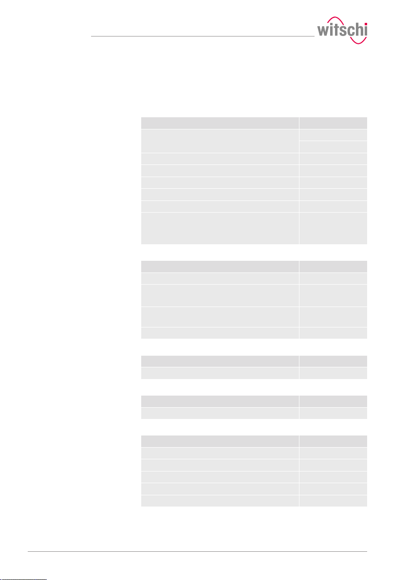
Maintenance
6.7 Accessories and spare parts
Ordering spare parts
Compressed air
To order accessories or spare parts, please contact Technical support [}
Page 7].
Find your nearest point of sale on our website www.witschi.com.
JunAir 6–10 compressor, 10 l with automatic
drainage
Compressed air connection with hose (2metres) 31.10.311
Compressed air hose (by the metre) KA05-1100P06-01
JUN-AIR special oil 0.5litres PA04-SJ27-OIL
T-compressed air connection KA03-3104-06-00
Exhaust air kit (without silencer) 31.24.050
Silencer incl. exhaust air kit
Noise reduction up to 40 dB(A)
Connection for up to 4 ProofMaster
Accessories Item no.
97.91.103 (230 V~)
97.91.104 (120V~)
31.24.051
Printing
Software
Power supply unit
Accessories
Accessories Item no.
Thermal printer JB01-SLK-TE25-S
Bluetooth Set II to Printer
(Plug-in unit + dongle)
USB Bluetooth dongle (for additional ProofMaster
devices)
Spare thermal paper roll for JB01-SLK-TE25-S JB01-MM60-740RS
Accessories Item no.
WiCoTRACE 3 enterprise
Accessories Item no.
Power supply unit 100–240VAC/12VDC/36W JA01-PSD40E120K3
Accessories Item no.
Seal (O ring) of the bell cover NA04-OR138x05
Support for small watches 31.24.702
Protective cover 31.24.04.30
USB cable, 1.8metres JB15-GD4520-BKK15
Bar code reader
95.15101
JB15-BT851-US
66 / 96 17.10.2019
Page 67
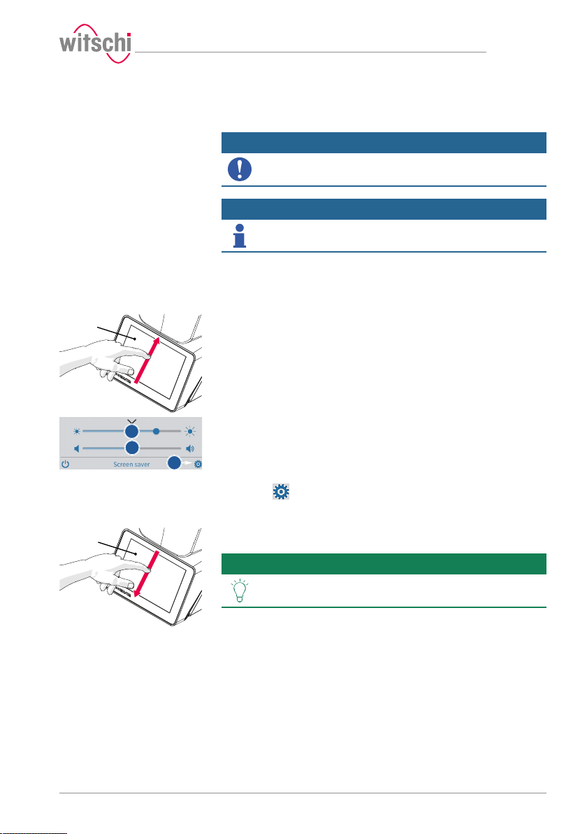
1
b
c
d
1
7 Settings
Mandatory
Info
7.1 Quick settings menu
Opening the quick settings
Closing the quick settings
ü The ProofMaster is switched on, see Switching on the
Proofmaster [}Page 34].
a) Swipe the touchscreen 1 with your finger in the direction of the
arrow.
b) Move the cursor left to decrease the brightness and right to
increase the brightness.
c) Move the cursor left to decrease the volume and right to increase
the volume.
d) Press to open the Settings menu.
a) Swipe the touchscreen 1 with your finger in the direction of the
arrow.
Settings
Programming is always done without running a test
sequence.
All procedures in this section start with displaying the
Settings menu.
ð The quick settings appear.
ð The settings window is closed.
Tip
Additional display and audio settings can be made.
See Display and audio settings [}Page 71].
17.10.2019 67 / 96
Page 68
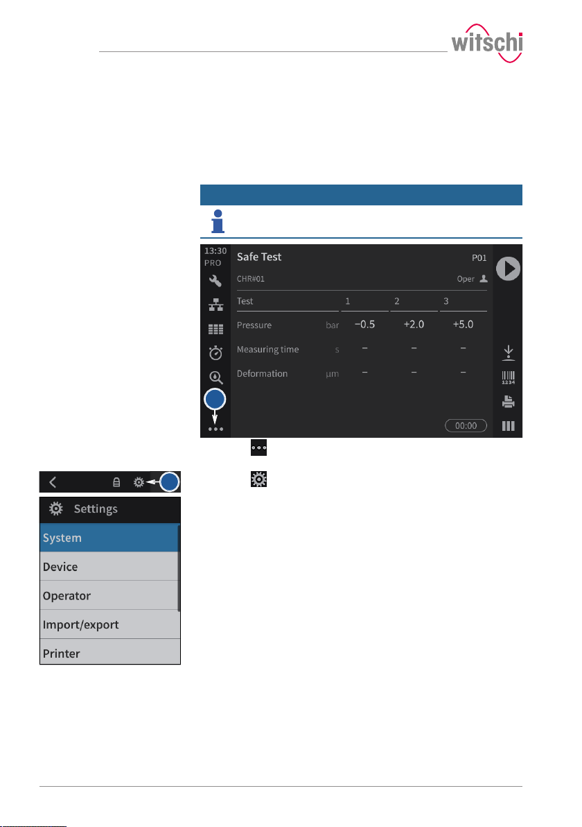
Settings
a
b
7.2 Settings
The settings of the ProofMaster can be changed in the settings. Proceed
as follows to recall the settings:
The ProofMaster offers quick access – see the Quick settings menu [}
Page 67] – and conventional access to the configuration menu settings.
Info
The functions of the keys are described in the Menus and
operating buttons [}Page 55] section.
a) Press (at the bottom left of the screen) to display the
expanded menu.
b) Press to access the configuration menus.
ð The configuration menus are displayed.
68 / 96 17.10.2019
Page 69
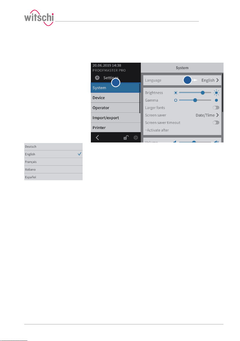
a
b
7.3 System
7.3.1 Language selection
Settings
a) Select System from the list.
ð System is highlighted in blue and the right window displays
the system options.
b) Tap the display language to open the selection window.
c) Select the desired display language from the list.
17.10.2019 69 / 96
Page 70
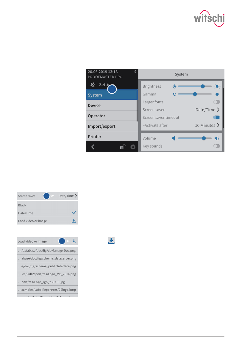
Settings
a
a
b
7.3.2 Screen saver
Selecting the screen saver
If the automatic screen saver function of the ProofMaster is activated,
the bell cover closes after the "Enable after" time set on the ProofMaster
and the screen saver is displayed.
a) Select System from the list.
ð System is highlighted in blue and the right window displays
the system options.
b) Configure the automatic screen saver according to your needs.
ð See the details below for the settings of each option.
a) Open the screen saver selection by tapping the current selection.
b) Choose between a black screen saver and a screen saver with
date and time. Alternatively, it is possible to import a screen saver.
Importing a screen saver
a) Insert a USB stick with the desired screen saver into the
ProofMaster.
b) Press to display the pictures and videos on the USB stick.
c) Select the desired picture or video from the list.
ð The display returns to the screen saver selection screen.
ð The selected image or video appears in the screen saver
selection list.
70 / 96 17.10.2019
Page 71
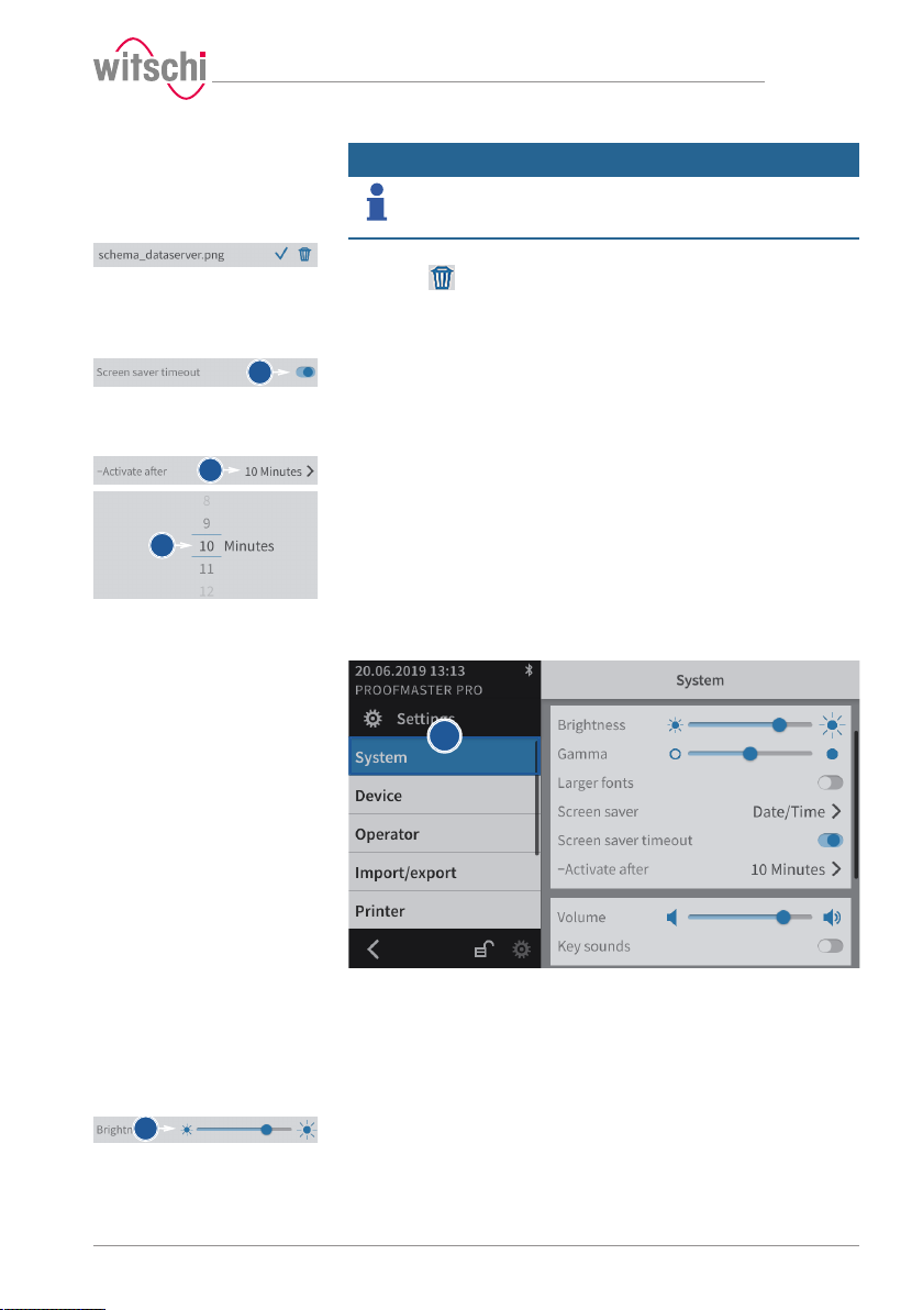
a
a
b
a
a
Settings
Deleting a screen saver
Enabling automatic
standby of the ProofMaster
Setting the automatic
standby activation time
Info
Only imported screen savers can be deleted.
The black screen saver and the screen saver with date and time are
system configurations.
a) Select the imported screen saver to be deleted.
b) Press to delete the desired imported screen saver.
a) Enable or disable the screen saver display.
ð The button is blue when the function is enabled and grey
a) Open the time selection for switching to standby by tapping the
current selection.
b) Select the desired time.
7.3.3 Display and audio settings
when it is not.
a) Select System from the list.
ð System is highlighted in blue and the right window displays
the system options.
b) Configure the display and audio settings as needed.
Brightness
17.10.2019 71 / 96
ð See the details below for the settings of each option.
a) Move the cursor left to decrease the brightness and right to
increase the brightness.
Page 72
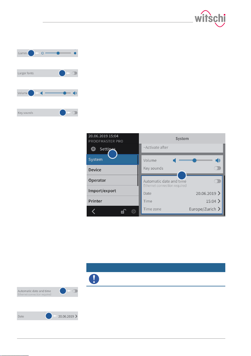
Settings
a
a
a
a
a
b
a
a
Contrast
Font sizes
Volume level
Enabling the button sound
7.3.4 Date & time
a) Move the cursor left to decrease the contrast and right to increase
the contrast.
a) Enable or disable the large font display.
ð The button is blue when the function is enabled and grey
when it is not.
a) Move the cursor left to decrease the volume level and right to
increase the volume level.
a) Enable or disable the button sound.
ð The button is blue when the function is enabled and grey
when it is not.
a) Select System from the list.
ð System is highlighted in blue and the right window displays
the system options.
b) Set the date and time.
ð See the details below for the settings of each option.
Automatically setting the
date and time
Setting the date manually
72 / 96 17.10.2019
When this function is enabled, the date and time of the unit are set
automatically.
Mandatory
The ProofMaster must have an Internet connection!
a) Enable or disable the automatic setting of the date and time.
ð The button is blue when the function is enabled and grey
when it is not.
ü The automatic setting of the date and time is disabled.
a) Open the date selection by tapping the displayed date.
Page 73
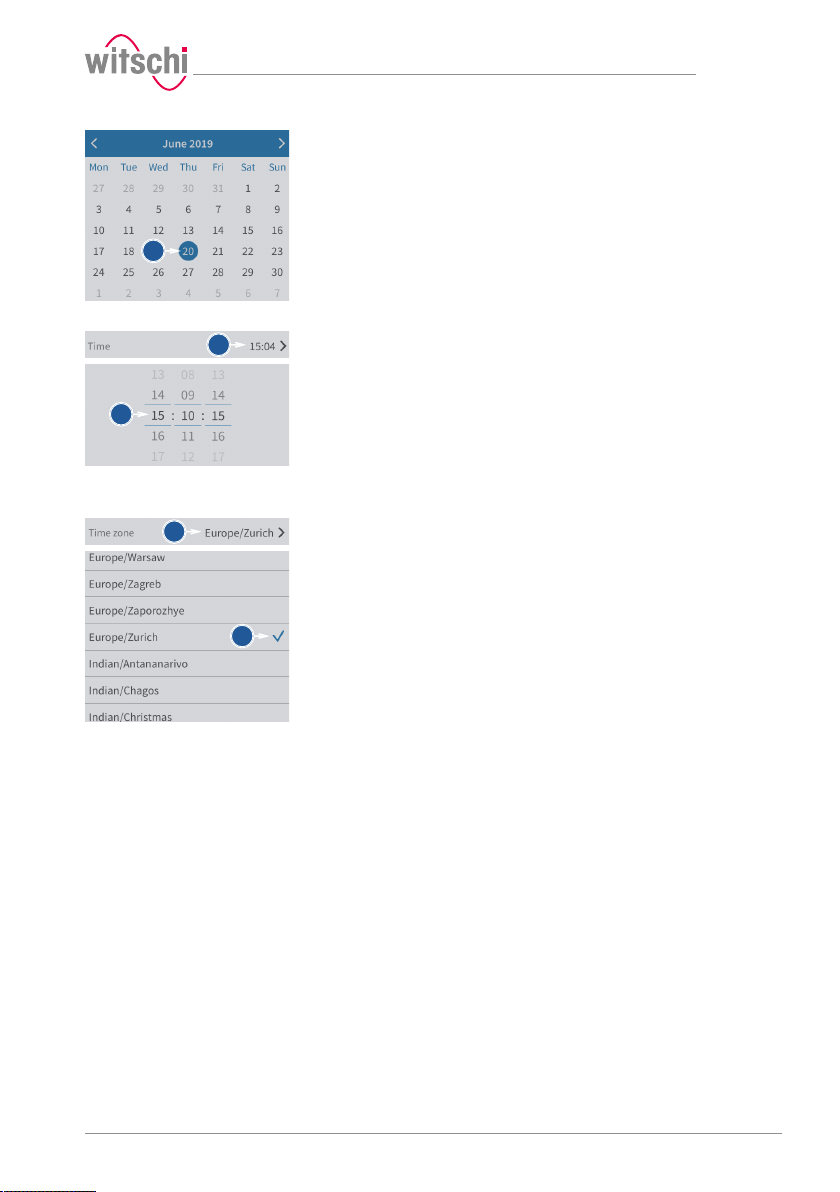
b
a
b
a
b
b) Select the desired date in the calendar.
Settings
Setting the time manually
Setting the time zone
manually
ü The automatic setting of the date and time is disabled.
a) Open the time selection by tapping the displayed time.
b) Select the desired time.
ü The automatic setting of the date and time is disabled.
a) Open the time zone selection by tapping the displayed time zone.
b) Select the desired time zone.
17.10.2019 73 / 96
Page 74
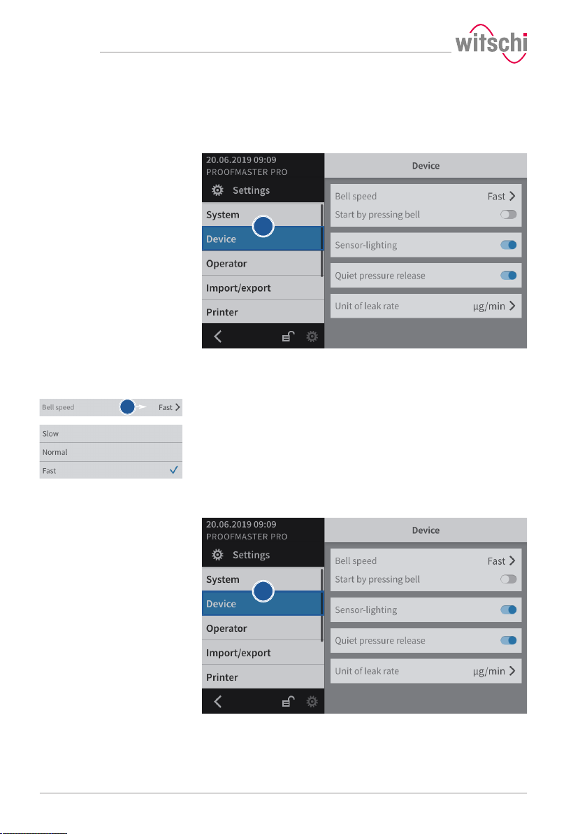
Settings
a
b
a
7.4 Device
7.4.1 Opening speed of the bell cover
a) Select Device from the list.
ð Device is highlighted in blue and the right window displays
the device options.
b) Open the bell cover speed selection by tapping the current
selection.
c) Select the desired bell cover speed.
7.4.2 Sensor lighting
a) Select Device from the list.
ð Device is highlighted in blue and the right window displays
the device options.
74 / 96 17.10.2019
Page 75
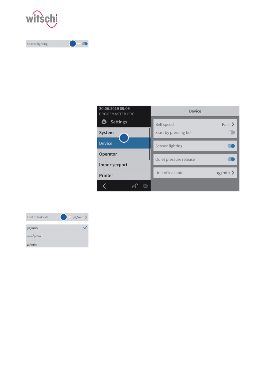
b
a
b
b) Enable or disable the sensor lighting.
7.4.3 Quiet pressure release
This setting allows the test pressure to be released more slowly from
the test chamber.
This reduces the noise emission but increases the test time.
7.4.4 Unit of leak rate
Settings
ð The button is blue when the function is enabled and grey
when it is not.
a) Select Device from the list.
ð Device is highlighted in blue and the right window displays
the device options.
b) Open the unit selection for the leak rate by tapping the current
selection.
c) Select the desired leak rate unit.
17.10.2019 75 / 96
Page 76
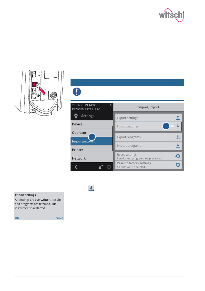
Settings
b
c
7.5 Import/export
7.5.1 Importing/exporting settings
The ProofMaster allows you to import and export these settings using a
USB stick.
Importing
a) Insert a USB stick with the settings into the ProofMaster.
Mandatory
The settings to be imported must be combined in a file
with the file name config.json.
Otherwise the ProofMaster will not find the settings to import.
b) Select Import/export from the list.
ð Import/export is highlighted in blue and the right window
displays the import/export options.
c) Press Import settings.
ð An information and confirmation window appears.
d) Press OK to confirm.
76 / 96 17.10.2019
Page 77
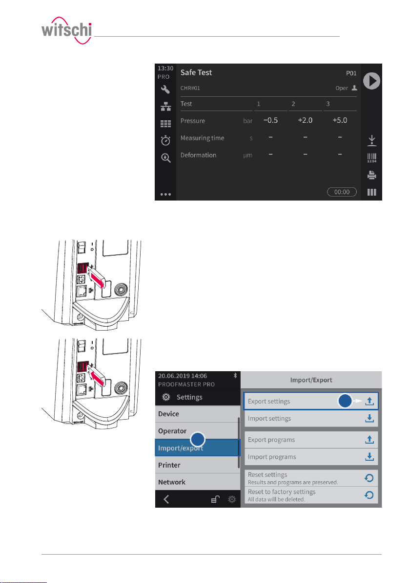
b
c
ð The home page is shown.
ð The settings of the ProofMaster have been replaced by the
settings imported from the USB stick.
ð The ProofMaster restarts.
e) Remove the USB stick.
Settings
Exporting
a) Insert the USB stick on which the settings are to be stored in the
ProofMaster.
17.10.2019 77 / 96
b) Select Import/export from the list.
ð Import/export is highlighted in blue and the right window
displays the import/export options.
Page 78
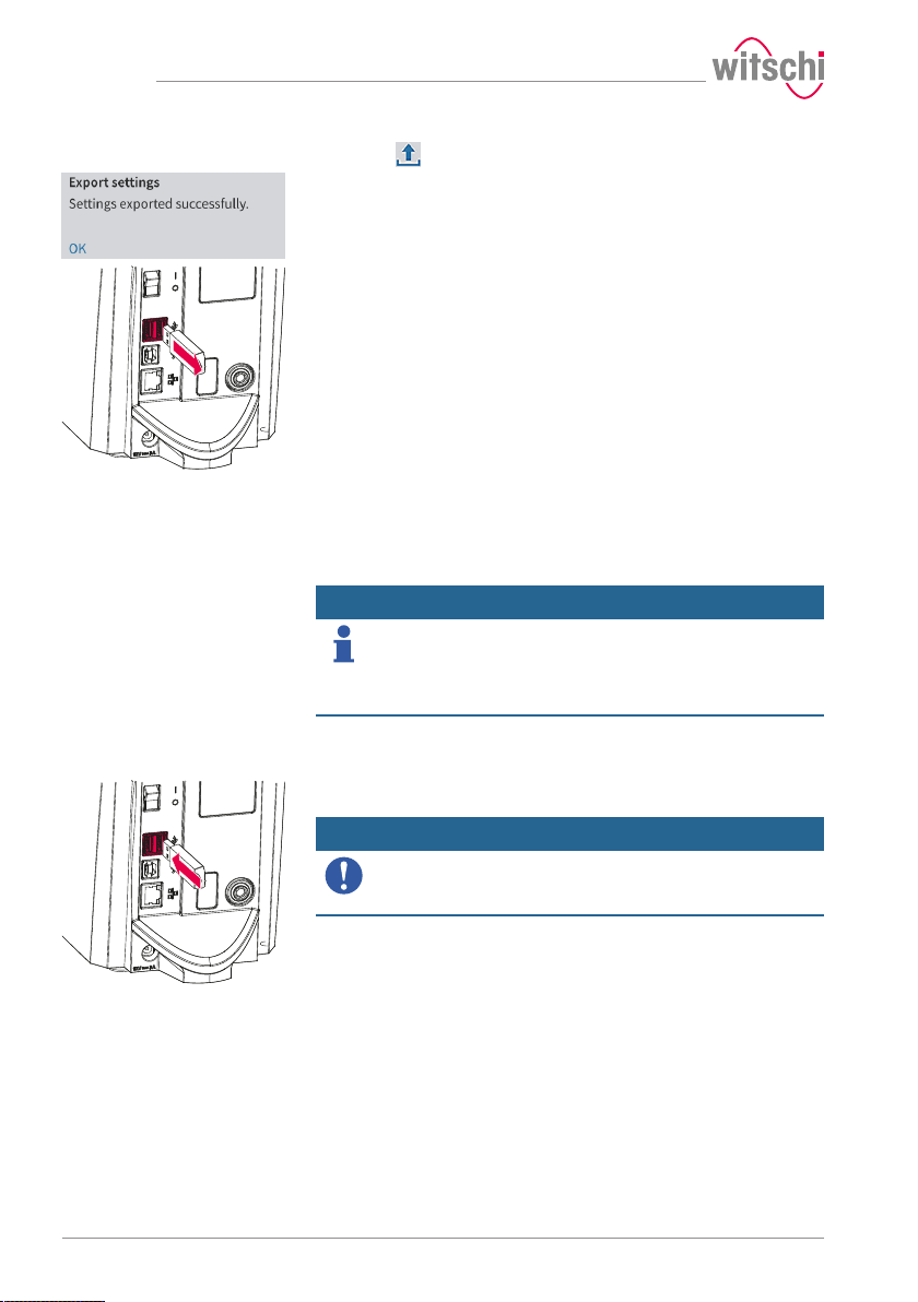
Settings
c) Press Export settings.
ð A window appears confirming the successful completion of
the settings export.
ð The settings of the ProofMaster were exported to the USB
stick in the config.json file.
d) Remove the USB stick.
7.5.2 Importing/exporting programs
The ProofMaster allows the import and export of programs within the
network or using a USB stick.
Importing/exporting programs over the network
Importing/exporting programs via USB stick
Info
The import and export of programs over the network takes
place automatically.
The WiCoTRACE XML_Server software updates its database and the
programs of all connected ProofMaster devices whenever a change is
made to a connected device or database.
Importing
a) Insert a USB stick with the programs into the ProofMaster.
Mandatory
The programs to be imported must be combined in a file
with the file name programs.json.
Otherwise the ProofMaster will not find the files to import.
78 / 96 17.10.2019
Page 79
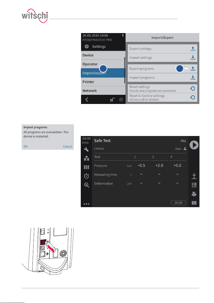
b
c
b) Select Import/export from the list.
ð Import/export is highlighted in blue and the right window
displays the import/export options.
c) Press Import programs.
ð An information and confirmation window appears.
d) Press OK to confirm.
Settings
ð The home page is shown.
ð The programs of the ProofMaster have been replaced by the
programs imported from the USB stick.
ð The ProofMaster restarts.
e) Remove the USB stick from the ProofMaster.
17.10.2019 79 / 96
Page 80
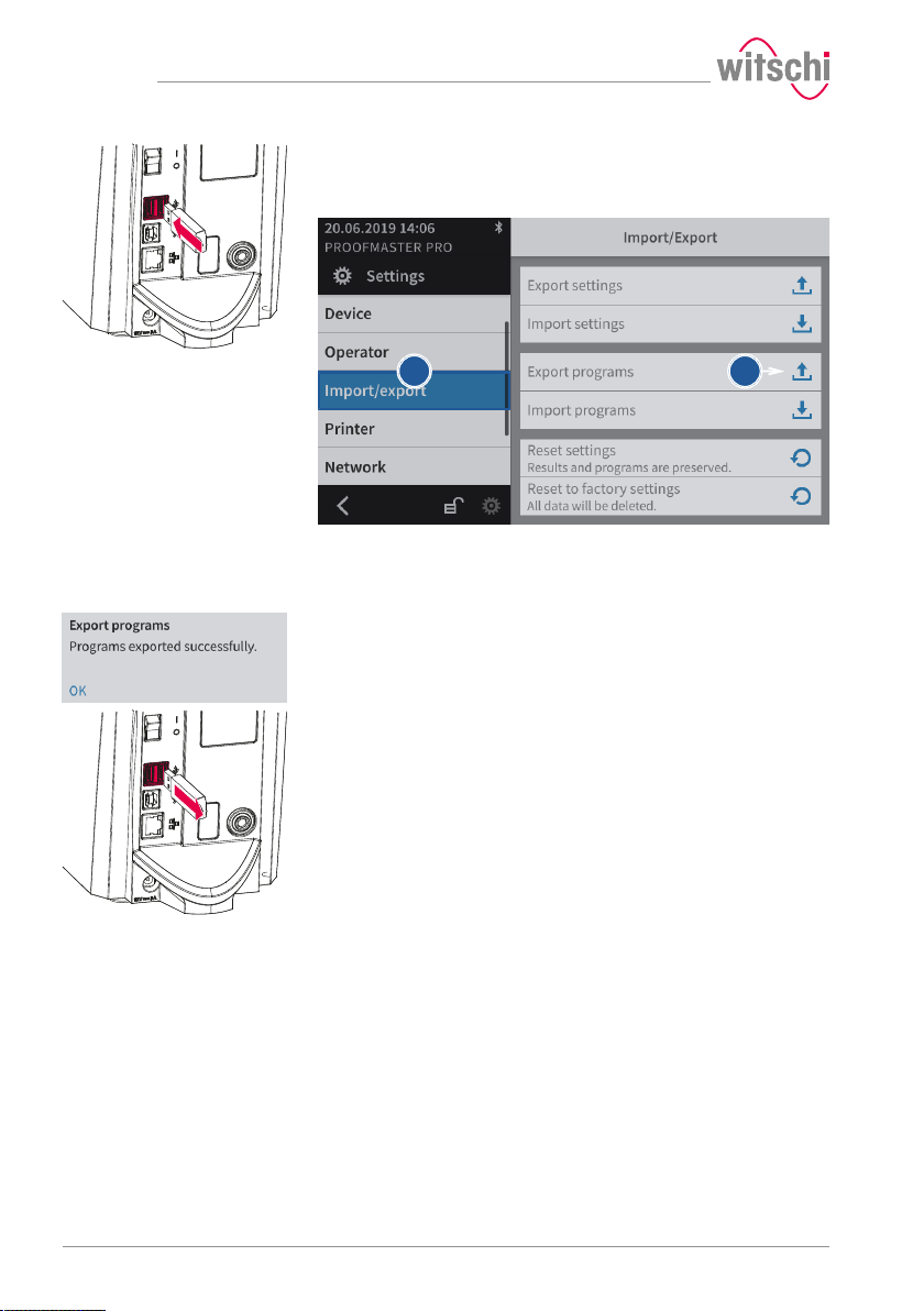
Settings
b
c
Exporting
a) Insert the USB stick on which the programs are to be stored in the
ProofMaster.
b) Select Import/export from the list.
ð Import/export is highlighted in blue and the right window
displays the import/export options.
c) Press Export programs.
ð A window appears confirming the successful completion of
the programs export.
ð The programs of the ProofMaster were exported to the USB
stick in the programs.json file.
d) Remove the USB stick from the ProofMaster.
80 / 96 17.10.2019
Page 81
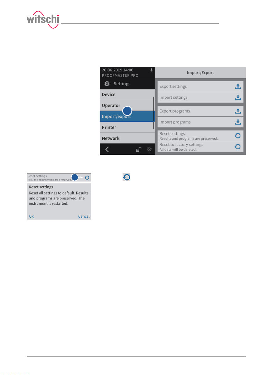
a
b
7.5.3 Resetting the device settings
This process restores the factory settings of the ProofMaster. The
programs and test results are retained.
a) Select Import/export from the list.
ð Import/export is highlighted in blue and the right window
displays the import, export and recovery options.
b) Press to reset the settings of the ProofMaster.
ð A confirmation window appears.
c) Press OK to confirm.
ð The ProofMaster restarts.
Settings
17.10.2019 81 / 96
Page 82
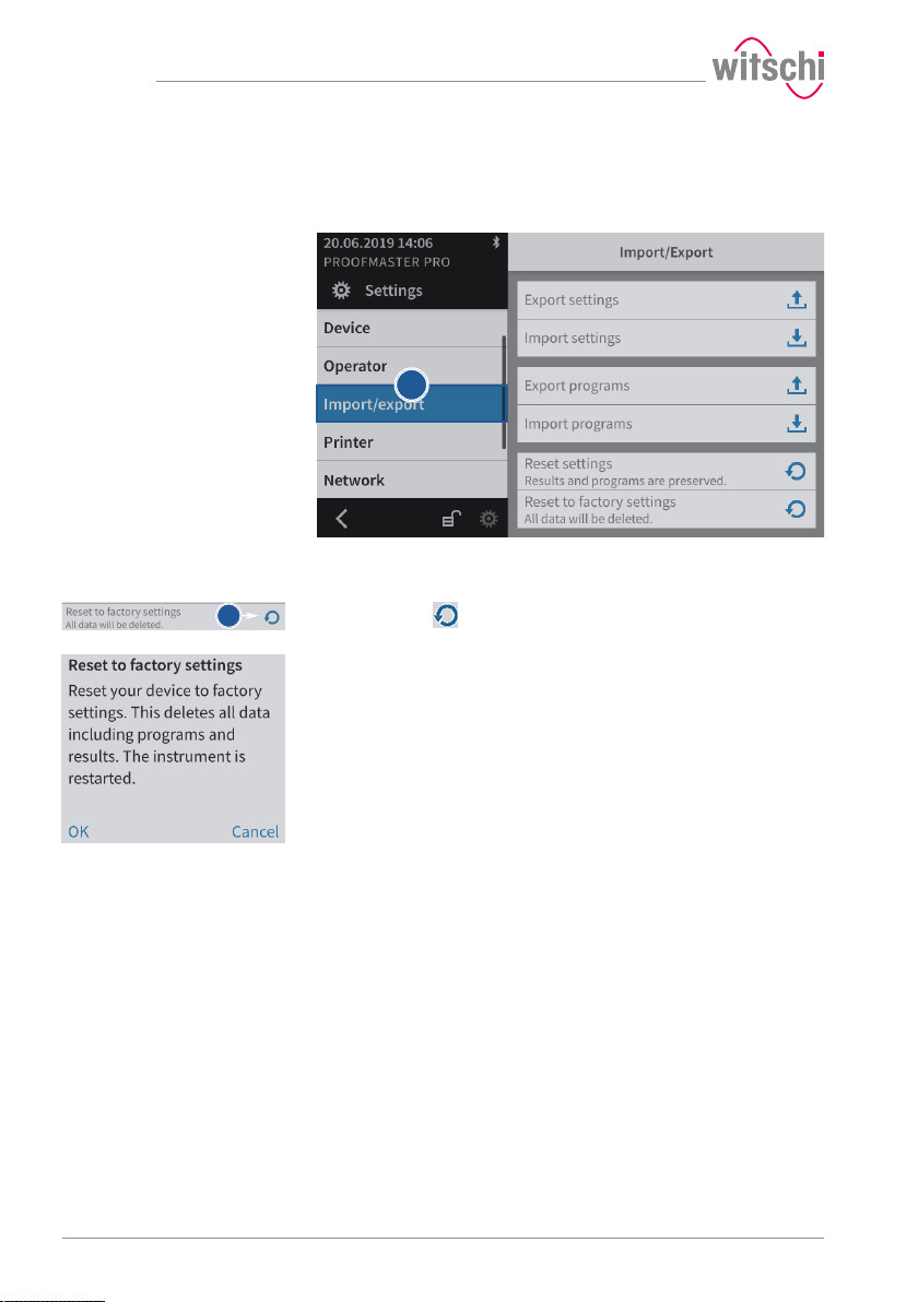
Settings
a
b
7.5.4 Restoring factory settings
This process restores the factory settings of the ProofMaster and
deletes all program data, measurement results, etc. on the device.
a) Select Import/export from the list.
ð Import/export is highlighted in blue and the right window
ð Press to restore the factory settings of the ProofMaster.
ð A confirmation window appears.
b) Press OK to confirm.
ð The ProofMaster restarts.
displays the import, export and recovery options.
82 / 96 17.10.2019
Page 83
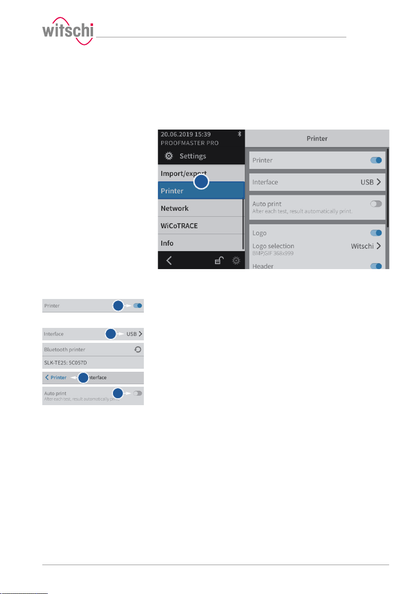
a
b
b
e
e
f
7.6 Printer
7.6.1 Configuring the printer
The configuration of the thermal printer is carried out on the
ProofMaster.
a) Select Printer from the list.
b) Enable the printer.
c) Open the user interface display by tapping the current selection.
d) Select the connection type.
Settings
ð Printer is highlighted in blue and the right window displays
the device options.
ð The button is blue when the function is enabled and grey
when it is not.
ð In the following example, Bluetooth.
e) Press < Printer to save and return to the previous screen.
f) If necessary, enable automatic printing.
ð The button is blue when the function is enabled and grey
when it is not.
g) If necessary, configure the label.
ð See Configuring the label [}Page 84].
17.10.2019 83 / 96
Page 84
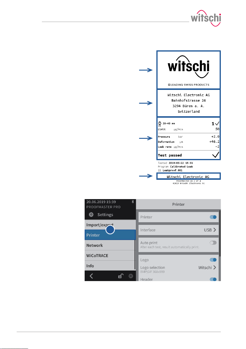
Settings
Logo
Header
Results
Footer
a
7.6.2 Configuring the label
Configurable areas
The figure above shows the different configurable areas of the label.
ü Printer configured.
a) Select Printer from the list.
ð Printer is highlighted in blue and the right window displays
84 / 96 17.10.2019
the printer options.
b) Configure the label as required.
ð See the details below for the settings of each option.
Page 85
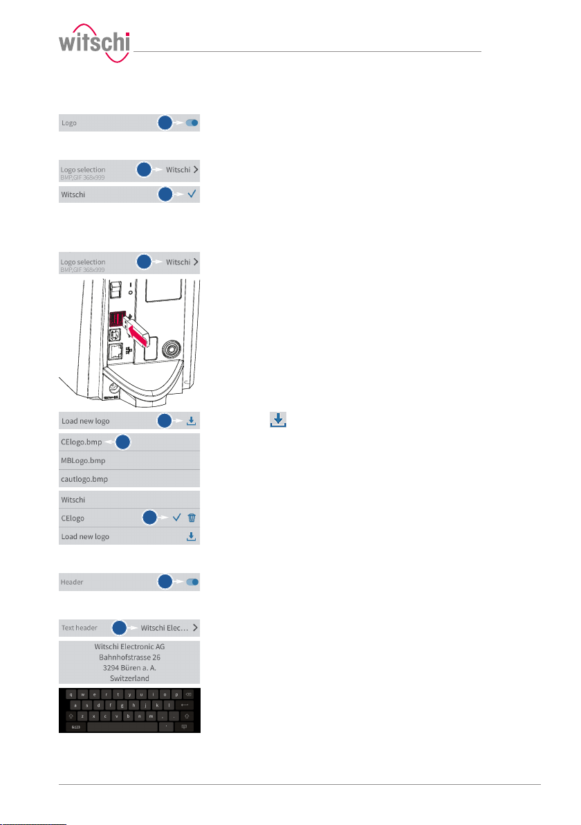
a
a
b
a
c
d
e
a
a
Settings
Printing the logo
Selecting the logo
Importing the logo
a) Enable or disable the printing of the logo.
ð The button is blue when the function is enabled and grey
when it is not.
a) Open the logo selection by tapping the name of the displayed logo.
b) Select the desired logo from the list.
ð In the above example, Witschi.
ð The Witschi logo is printed on the label.
a) Open the logo selection by tapping the name of the displayed logo.
b) Insert a USB stick with the desired logo into the ProofMaster.
c) Press Load new logo.
d) Select the desired logo from the list.
ð All image files (png, jpg, bmp, tec etc.) on the USB stick
appear in the list.
ð In the above example, selection of CElogo.
ð The CElogo is now in the list and selected.
ð The CElogo logo is printed on the label.
Printing the header
Configuring the header
a) Enable or disable the printing of the header.
ð The button is blue when the function is enabled and grey
when it is not.
a) Open the header configuration by tapping the beginning of the
displayed header.
b) Tap on the text area to open the alphanumeric keypad.
c) Enter the header using the alphanumeric keypad.
ð 4lines with maximum 30characters.
ð The entered header is printed on the label.
17.10.2019 85 / 96
Page 86
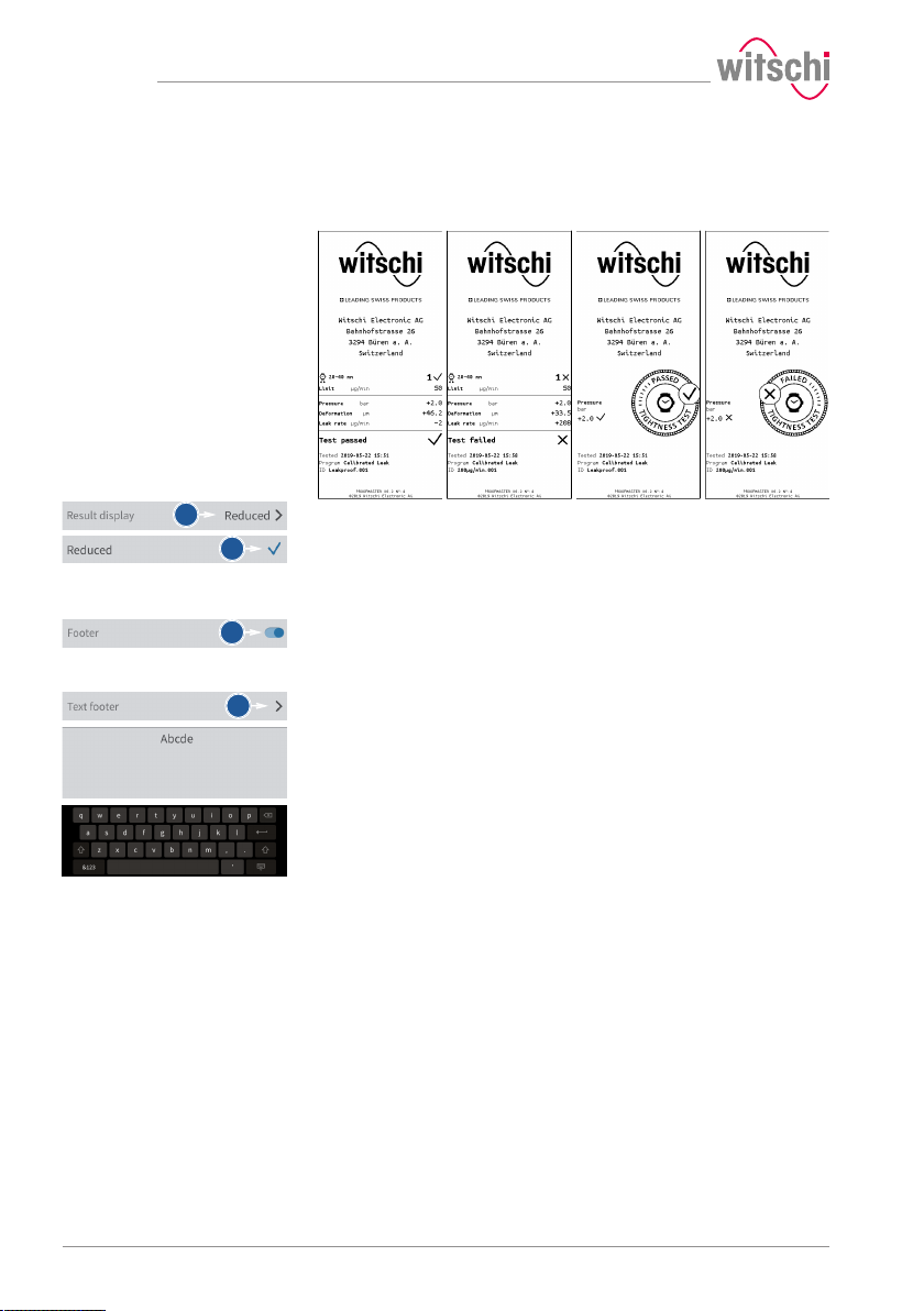
Settings
Numeric format Reduced format
OK Not OK OK Not OK
a
b
a
a
Selecting the results display
Printing the footer
Configuring the footer
The measurement result can be displayed in numeric or reduced form.
See examples below.
a) Open the results display by tapping the displayed selection.
b) Select the desired display type.
ð In the above example, Reduced.
a) Enable or disable the printing of the footer.
ð The button is blue when the function is enabled and grey
when it is not.
a) Open the footer configuration by tapping the beginning of the
displayed footer.
ð In the following example, no text is entered in the footer.
b) Tap on the text area to open the alphanumeric keypad.
c) Enter the footer using the alphanumeric keypad.
ð 4lines with maximum 30characters.
ð The entered footer is printed on the label.
86 / 96 17.10.2019
Page 87
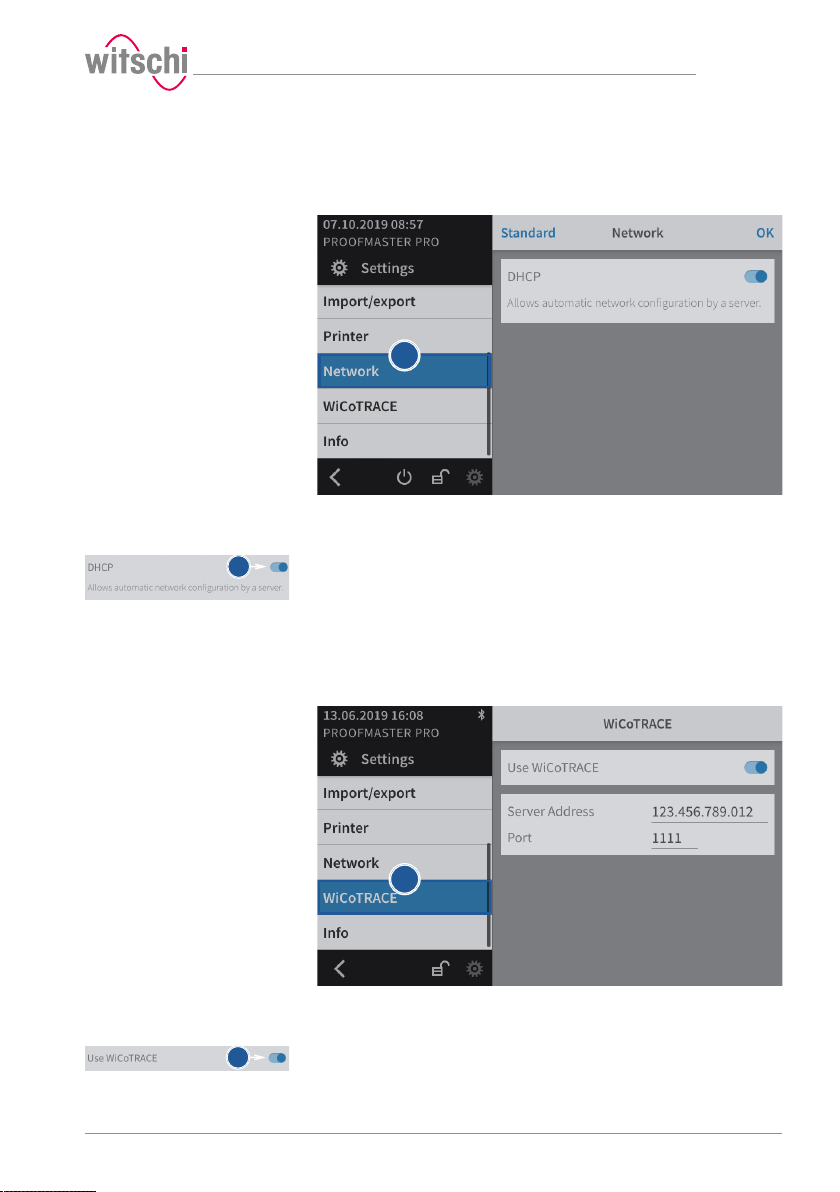
a
b
a
b
7.7 Network
7.8 WiCoTRACE
Settings
The connection option allows automatic configuration of the
ProofMaster with the help of a server.
a) Select Network from the list.
ð Network is highlighted in blue and the right window displays
the network options.
b) Enable or disable the network.
ð The button is blue when the function is enabled and grey
when it is not.
The ProofMaster must be configured for use with the WiCoTRACE
software.
a) Select WiCoTRACE from the list.
ð WiCoTRACE is highlighted in blue and the right window
17.10.2019 87 / 96
displays the options for WiCoTRACE.
b) Enable or disable the use of WiCoTRACE.
ð The button is blue when the function is enabled and grey
when it is not.
Page 88
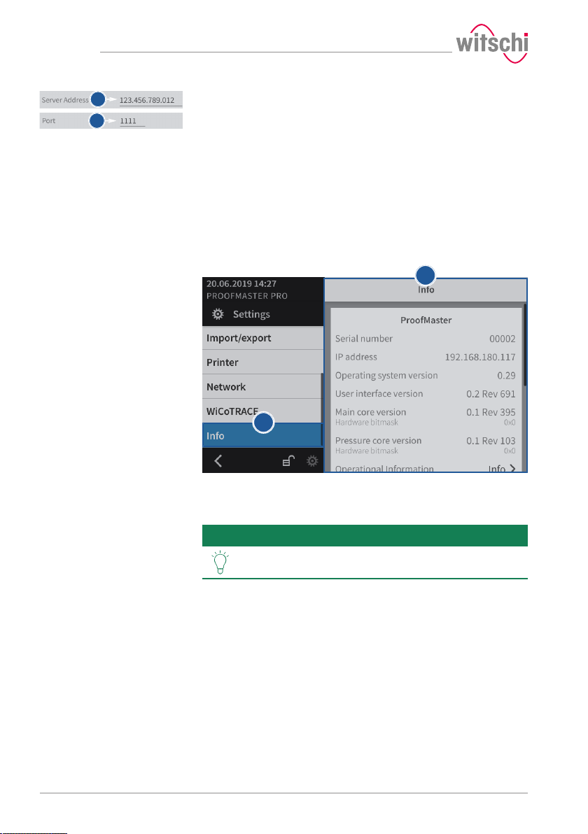
Settings
c
d
a
1
c) Enter the IP address of the server where WiCoTRACE is located.
d) Enter the port of the server where WiCoTRACE is located.
7.9 System information
This menu displays the following information:
• Serial numbers
• IP address
• Versions of the different systems and programs
• Information on device operation (cycle counter, measuring counter, etc.)
• Last calibration
• Legal information (licenses)
ð The ProofMaster is connected to the WiCoTRACE software.
a) Select Info from the list.
ð Info is highlighted in blue and the right window displays the
system information 1.
Tip
Use the scroll bar on the right side of the window to
display non-visible information.
88 / 96 17.10.2019
Page 89
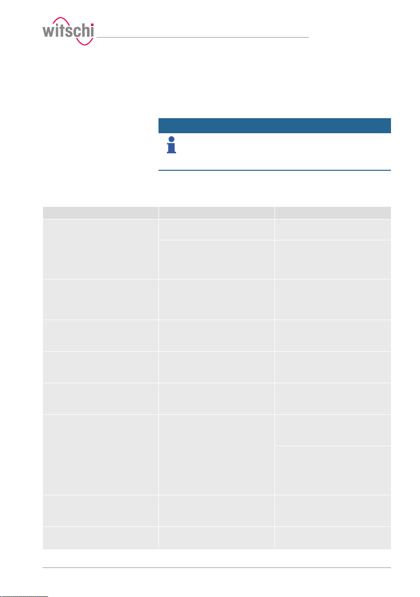
8 Troubleshooting
8.1 Error messages
Info
Error messages appear in the event of a malfunction in the
device.
The following table provides information about the possible causes of an
error message and information on how to correct it.
The most important faults are described below. Contact customer
service if the fault persists after all possible repair options have been
carried out.
Error message Cause Remedy
No or too low inlet pressure
available!
Test pressure cannot be reached.
No test specimen detected!
Deformation sensor has reached
lower limit. It is likely that no test
specimen has been inserted.
Bell cover blocked!
Please check if free movement is
possible.
Hook blocked!
Please check if free movement is
possible.
Deformation sensor blocked!
Please check if free movement is
possible.
Positive or negative pressure in test
chamber!
Chamber cannot be opened or
closed.
Communication error!
Check whether the deformation
sensor is fitted.
No printer found!
Check printer and USB port.
Inlet pressure is too low. Check the compressor's output
The maximum vacuum that can be
generated depends on the current air
pressure (location, altitude above sea
level).
No test specimen was inserted. Insert test specimen.
Object jammed. Remove object.
Object jammed. Remove object.
Object jammed. Remove object.
Pressure could not be released from
the chamber.
Deformation sensor was not correctly
fitted.
Deformation sensor was not correctly
fitted.
Printer not switched on. Check printer and USB cable.
pressure.
The output pressure must be at least
1 bar higher than the chosen test
pressure.
If bell cover is open:
Check whether the deformation
sensor is correctly fitted.
If bell cover is closed:
Release the pressure manually and
open the bell cover (See Opening the
bell cover in an emergency [}Page
91]).
Check whether the deformation
sensor has been correctly fitted.
Troubleshooting
17.10.2019 89 / 96
Page 90
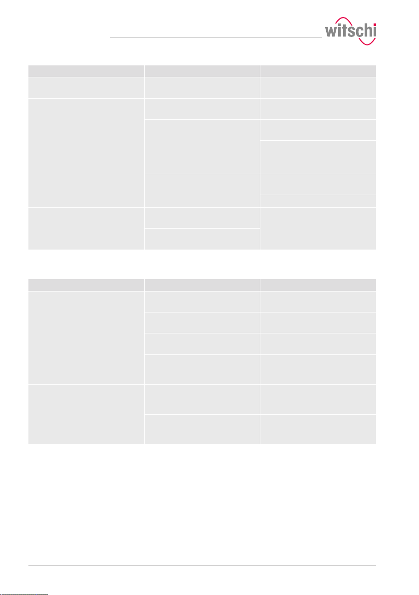
Troubleshooting
Error message Cause Remedy
WiCoTRACE (SMX service) error!
No connection to the SMX service
could be established.
WiCoTRACE (SMX service) error!
No response received from SMX
service.
Vibration detected
The measurement result is unreliable.
Resume measurement?
USB cable defective or not correctly
connected.
Ethernet cable defective or not
correctly connected.
WICoTRACE configuration not set up
correctly.
Ethernet cable defective or not
correctly connected.
WICoTRACE configuration not set up
correctly.
A vibration was detected during the
test.
Vibrations could distort the
measurement result.
Check Ethernet cable.
Check if the SMX service is started
correctly by WiCoTRACE.
Check WiCoTRACE configuration.
Check Ethernet cable.
Check if the SMX service is started
correctly by WiCoTRACE.
Check WiCoTRACE configuration.
Install the test device at a suitable,
vibration-free location.
8.2 Malfunctions
Description of malfunction Cause Solution
Incorrect test result The watch is not positioned correctly. Reposition the watch. See
Adhesive or protective foil on the
watch case.
The watch is not at ambient
temperature.
More and more incorrect test results
occur. The device is not properly
calibrated.
Test results are not being printed There is no more paper in the printer. Insert a new paper roll. Please refer
Automatic printing of test results is
not enabled.
Positioning the watch [}Page 42].
Remove the adhesive or protective
foil.
Wait until the watch has warmed up
or cooled down. Repeat the test.
Have the device calibrated by
customer service. See Technical
support [}Page 7].
to the manufacturer's documentation
for more information.
Enable automatic printing of test
results. See Configuring the printer [}
Page 83].
90 / 96 17.10.2019
Page 91
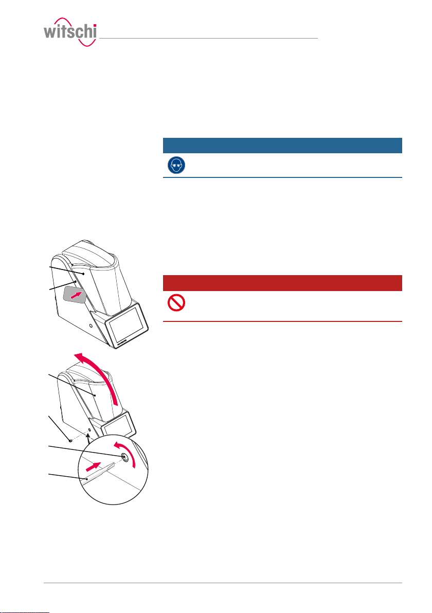
1
2
3
4
5
1
8.3 Opening the bell cover in an emergency
The bell cover can be opened manually in the following cases:
• The test was cancelled. The watch has to be removed from the test
chamber.
• The test chamber does not open automatically, for example after a
power failure.
Mandatory
Wear safety goggles during the entire bell cover opening
process!
a) Switch off the compressor as specified in the manufacturer's
documentation.
b) Release the air from the compressed air hose of the compressor.
c) Switch off the ProofMaster.
ð The remaining pressure in the test chamber escapes.
ð See Switching off the device [}Page 36].
d) If the residual pressure does not escape from the test chamber,
carefully insert a thin, rounded object between the bell cover 1 and
the bottom 2.
Prohibition
Do not use a pointed object to open the bell cover!
Pointed objects can lead to material damage (seal) or scratches.
• Use objects with rounded corners, eg. playing cards.
ð The pressure is released.
e) Wait until the pressure has completely dissipated.
Troubleshooting
f) Remove the cap 3.
g) Insert a size 4 or 5 5 screwdriver into hole 4 and turn clockwise to
release the bell cover 1.
h) Open the bell cover 1.
17.10.2019 91 / 96
Page 92
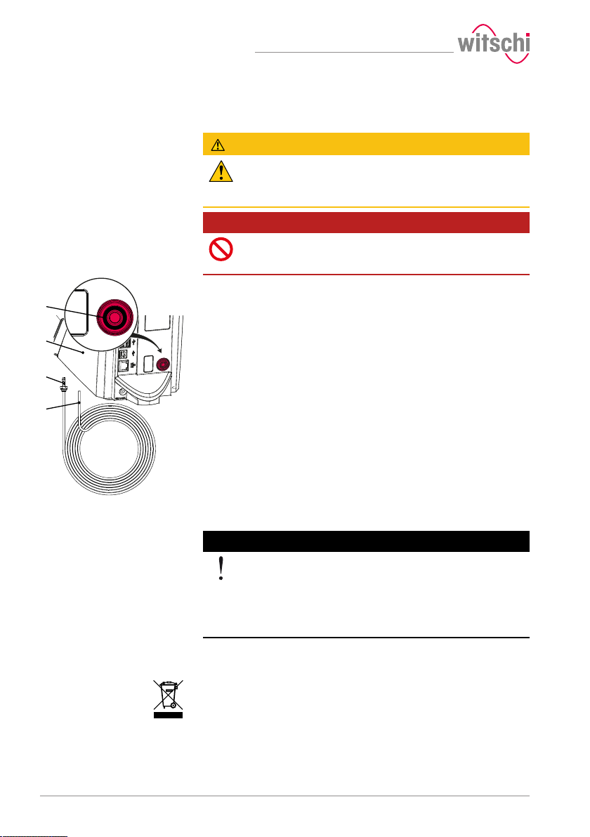
Decommissioning and disposal
1
2
3
4
9 Decommissioning and disposal
Decommissioning
Disposal
Electrical and electronic
components
CAUTION
Risk of injury from compressed air!
If compressed air escapes uncontrolled, there is a risk of injury.
• Take care when working on the compressor or the compressed air
hoses.
Prohibition
Never force the device cover to open when the device is
under pressure!
Otherwise parts could be ejected.
ü The ProofMaster is switched off.
a) Switch off the compressor as specified in the manufacturer's
documentation.
b) Disconnect the compressor from the compressed air hose as
specified in the manufacturer's documentation.
c) Press the ring 1 and disconnect the compressed air hose 2 from
the ProofMaster 3.
d) Switch off the other used accessories properly.
e) Pull out all cables (USB/Ethernet).
f) Disconnect the power supply unit connection from the local mains
network.
g) Disconnect the power supply unit connection from the power
supply connection of the ProofMaster 4.
ð The ProofMaster is non-operational.
If no return or disposal agreement has been made, return the device to
a recycling point.
Caution - environmental
Improper disposal poses an environmental hazard!
Improper disposal can result in environmental pollution.
• Always contact a specially approved body for disposal of the
device.
• If there is any uncertainty, contact the local government or a
company specialising in waste management to find out about the
conditions for environmentally sound disposal.
Electrical and electronic components must not be disposed of with
household waste, but must be disposed of at a recycling centre or a
specialised company.
92 / 96 17.10.2019
Page 93
10 Technical data
Technical data
Mass and weight
Performance data
Mains supply connection
values
Power supply unit output
values
Compressed air connection
Designation Value Unit
Weight 5.8 kg
Width 149 mm
Height when bell cover is closed 243 mm
Height when bell cover is opened 370 mm
Depth 305 mm
Designation Value Unit
Vacuum range -0.1 to -0.8 bar
Pressure range 0.1 to 10 bar
Accuracy of test pressure ± 80 mbar
Designation Value Unit
Mains voltage 100 to 240 VAC
Mains frequency 50/60 Hz
Designation Value Unit
Voltage 12 VDC
Maximum current consumption 3.0 A
Maximum power consumption 36 W
Designation Value Unit
Maximum supply pressure 12 bar
Supply pressure for operation of the device
with maximum
power
Compressed air consumption per pressure
test
Compressed air consumption per vacuum
test
Compressed air quality Dry and dust-
11 bar
10 l/test
40 l/test
free
Measuring characteristics
17.10.2019 93 / 96
Designation Value Unit
Measuring time 20 to 600 s
Leak tightness limit
(Unit selectable: µg/min, mm3/min, µl/min)
10 to 999 µg/min
Page 94
Technical data
Designation Value Unit
Measurement resolution 0.01 µm
Ambient conditions
Emissions
Designation Value Unit
Temperature 15 to 35 °C
Relative humidity (non-condensing) Max. 80 %
Designation Value Unit
Noise emissions < 80 dB(A)
Noise emission with "Quiet pressure release"
See Quiet pressure release [}Page 75].
< 70 dB(A)
94 / 96 17.10.2019
Page 95

Notes
17.10.2019 95 / 96
Page 96

Witschi Electronic AG
Bahnhofstrasse 26
3294 Büren an der Aare
Switzerland
+41 32 352 05 00
www.witschi.com
 Loading...