

Page 1
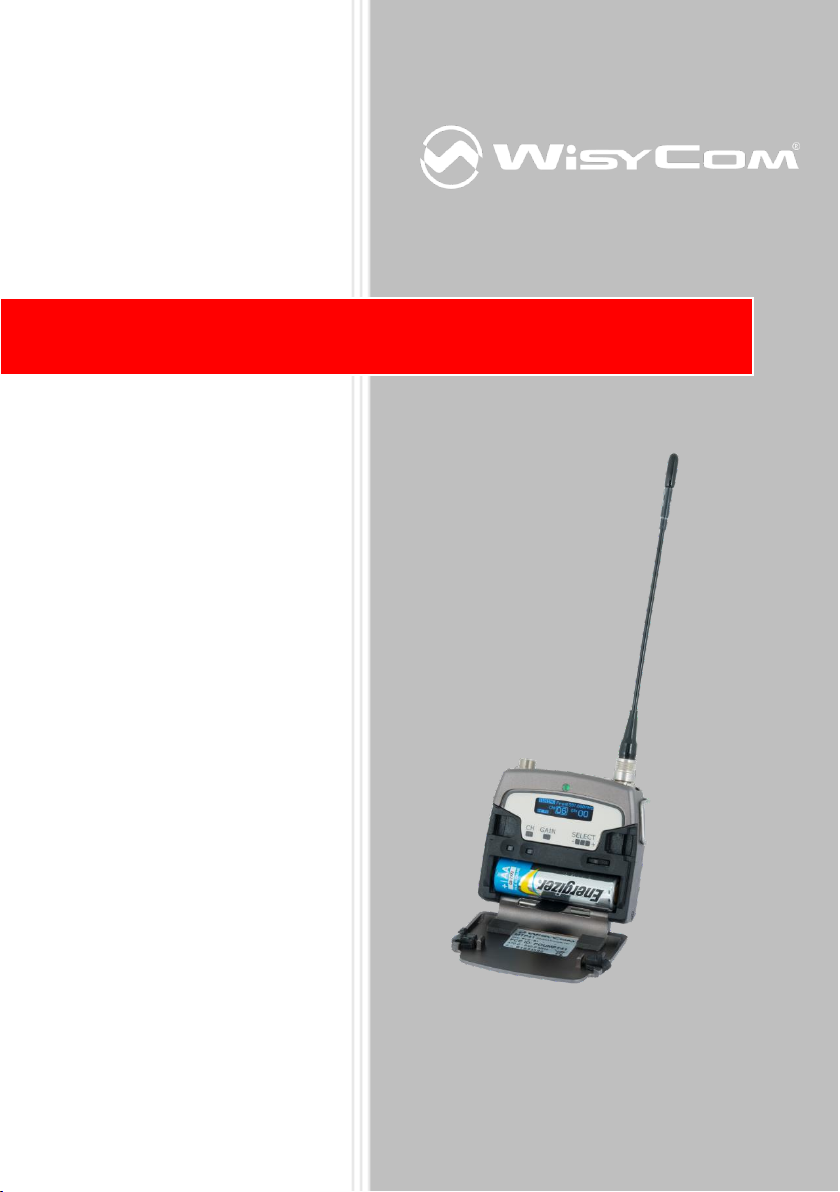
MTP41 User Manual
Wideband Wireless
Professional Pocket
Transmitter
SN: ________________
Rev.01 (rif. FW 1.11_0D)
Date: 10 October 2013
MTP40
Page 2
INTRODUCTION
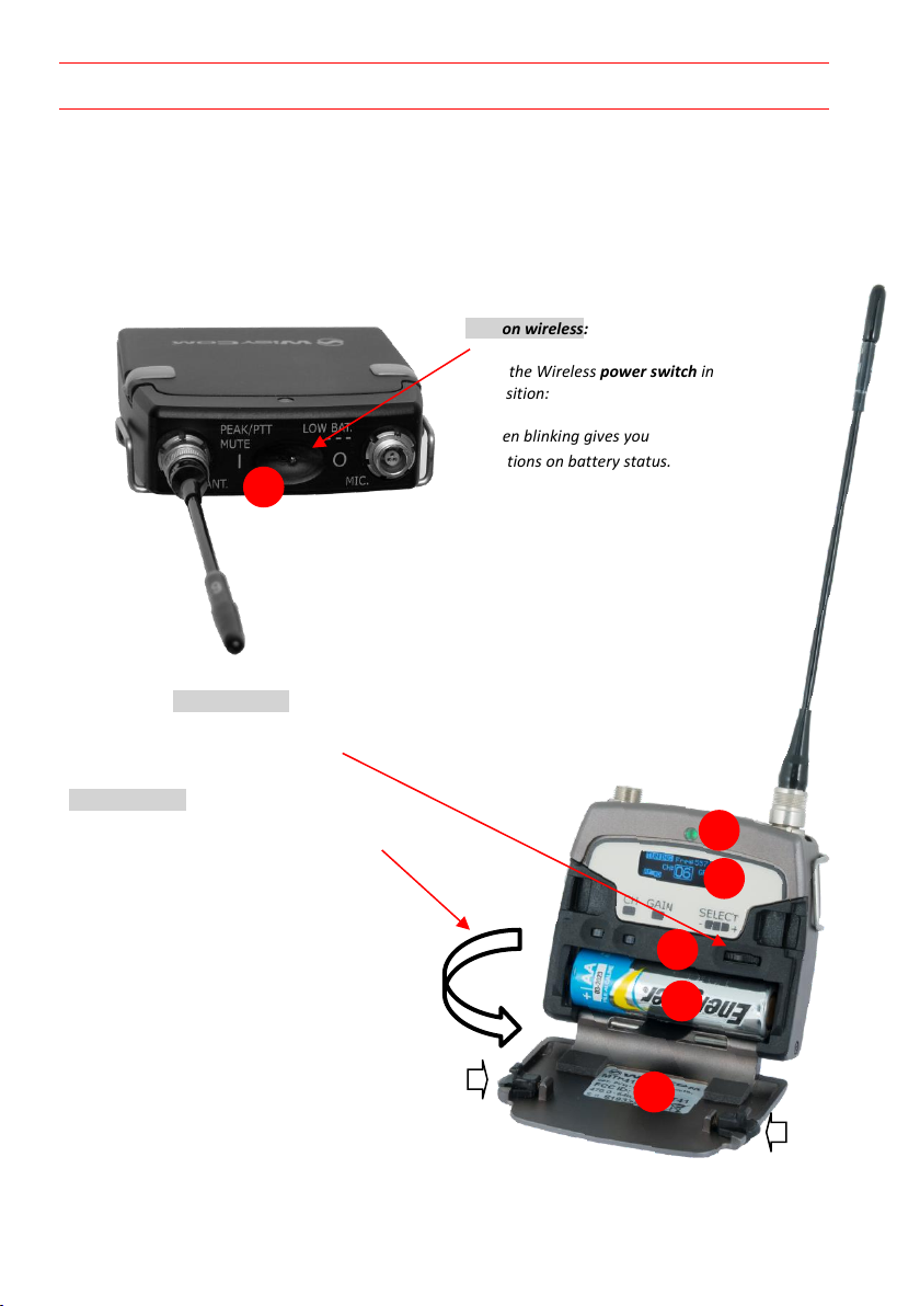
❶
Switch to enable wireless transmission it
also indicates the battery status and
peak/mute operation (with PTT)
❷
LED to show information on RF
transmission/battery status/modulation
peek/PTT status
❸
Oled display for transmitter setup
❹
<ch>, <gain> and 3 positions <selector>
❺
Battery holder
❻
Cover (to open push side buttons)
Turn on wireless:
Move the Wireless power switch in
“I” position:
A green blinking gives you
indications on battery status.
1
Open MIC Body:
Push the side buttons and flip down the cover, to access
internal setup controls and batteries.
Turn on display:
Push <select switch> and hold it.
2
3
5 6 4
“MTP41 is an extremely small and light pocket transmitter especially designed for
professional wireless microphone applications”
Very easy and quick to use thanks to OLED display, dedicated buttons and a joggle selector.
MTP41 benefits also of the latest Wisycom RF technology along with an enhanced
robustness against noise and inter-modulation.
Fig. 1
1.
Fig. 2
Page 3

SAFETY INSTRUCTION
Read this safety instruction and the manual first
Follow all instructions and information.
Do not lose this manual.
Do not use this apparatus under the rain or near the water.
Do not install the apparatus near heaters or in hot environments, do not use outside the
operating temperature range.
Do not open the apparatus, only qualified service technician are enabled to operate on it.
The apparatus needs servicing when it is not properly working or is damaged by liquids,
moisture or other objects are fallen in the apparatus.
Use only accessories or replacement parts authorized or specified by the manufacturer.
Clean the apparatus only with dry cloths, do not use liquids.
Report the serial number and the purchasing date in front of the manual. It is needed to
have proper replacement parts or accessories from the manufacturer.
When replacement parts are needed, use only replacement parts authorized from the
manufacturer. Substitution with not authorized parts could result in electric shock,
hazards or fire.
Keep attention on all the labels with warnings or hazards on the apparatus.
MTP41 TRANSMITTER FEATURES
Led indications
Led indication with bi-colour led (red & green) on front ❷:
- Wireless transmission status: green when RF transmission power is on.
- Battery status: green steady, slowly blinking (< 25%), quickly blinking (<12%).
- Modulation peak (if activated): red.
- PTT status: red if active (push to talk “pushed”).
Batteries
MTP41 is working with 1 AA alkaline or NiMH or Lithium battery (select correct type on setup
controls). Battery status can be checked on internal OLED display or looking to LED status on
front ❷.
BATTERY SUBSTITUTION
Open transmitter cover and insert the battery following polarity indicated.
Page 4
A
B C D
Antennas
Band
Range
(MHz)
Code
1 470-640 MHz
470-547
507
547-640
590
2 566-798 MHz
566-672
616
672-798
732
3 510-698 MHz
510-595
552
595-698
646
+
-
CLICK
Antenna Code label
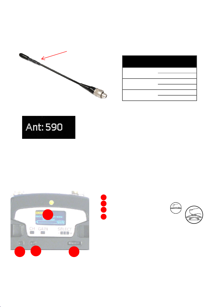
MTP41 is supplied with a couple of antennas. According to the working band, different
antenna models can be supplied. All the models have black cap and a black label with code in
white colour. For more details see the
below table.
In order to help the user to connect the correct antenna,
the display shows the antenna code during the switch on of
the transmitter and during the tuning selection after a
change of frequency range. (ex. if the user changes the
frequency from 566 to 672 MHz, the display shows Ant. 732)
Powering up
Move the wireless power switch (see Fig. 1) in “I” position to activate wireless transmission:
the front green LED ❷ lights up (blinking when battery is low!)
Setup control
Open transmitter Body to access the “display and controls” area (Fig. 3):
A. Graphics Display (OLED)
B. Channel selection buttons (ch)
C. MIC gain setup buttons (gain)
D. 3 position selector (up / down / click)
Fig. 3
Page 5
+
-
CLICK
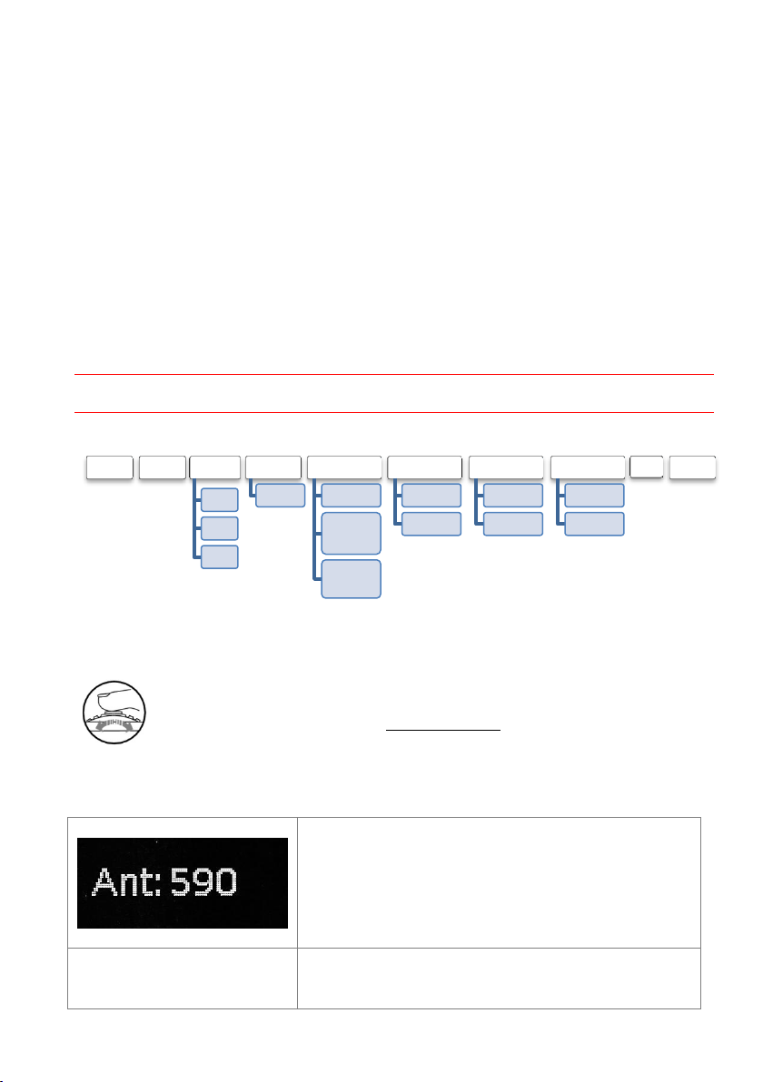
OLED Power UP (OLED IS IN OFF CONDITION)
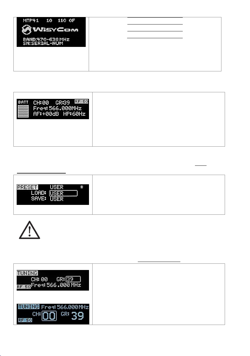
First one gives information of antenna to be used. The
number displayed is the center-band of the antenna to
be used.
The second menu gives indication on product:
- product id (MTP41),
- a number which identify the working band
STATUS PRESET TUNING
CH
GR
Freq
AUDIO
AF Gain
AUDIO
Phase
Noise
Reduction
High Pass
Filter
RF/BATTERY
RF Power
Battery
LED
Led Light
Led Mode
MIC
Mode
PTT Mode
IRDA
Lock
Pushing down selector (click), oled turns on. A first menu with Serial Number and brand logo is
displayed, then <status> menu enters automatically.
Turn on the transmitter pushing and holding selector (click) > 2 sec, Serial Number menu is
displayed till (-/+) is selected.
OLED Power DOWN (OLED IS IN ON CONDITION)
Pushing and holding selector (click) > 2 sec, display is turned off.
Display turns off automatically after 15 sec, unless in <IRDA> menu or in <AUDIO> menu (with
audio level < 5% from nominal).
MENU NAVIGATION
Setup menu are accessed in sequence:
Using <+/-> selector all menus can be accessed in sequence, push <click> to enter edit mode:
<+/-> to setup field
<click> again to confirm changes and exit.
exit without confirmation if no button is pressed after a few seconds time out.
<START UP> menu
These menus are displayed during power up for few seconds.
Page 6
1
470-640
2
566-798
3
510-698
- a number which identify the hardware version
- the firmware release (ex. 110.0F),
- the band in extended format and
- the serial number.
Keep selector pushed to hold this menu!
<STATUS> menu
Major info are displayed:
- Current channel/group (i.e. CH:00 GR:39)
- Current frequency (i.e. 566.000 MHz)
- Mic gain (i.e. AF: +00dB) and high pass filter (i.e.
HP:60 Hz)
- “RF 50” or “RF 10” on top right if RF transmission
is on at high or low power respectively
- On left side, the battery bar is displayed
MTP41 can recall configuration presets. “FACTORY”
recalls the Wisycom factory configuration. “USER” recalls
the user configuration (the transmitter configuration is
copied into the USER using the “save to” submenu). All
“USER” menus are not locked by default,
thus this is quick way to unlock features!
In this menu current channel/group and frequencies can
be setup. Use the selector to change values (<+/->) and
<click> to confirm.
Sync group is a quick self-settable channel synchronized
by receiver.
Using quick channel setup buttons (<CH>), it is possible to
enter quickly in the tuning menu. Note that the menu has
a different layout (see the side image)
This is the first menu displayed after power up.
<PRESET> menu
This menu can be entered by scrolling selector, or pushing at the same time both quick
channel setup buttons (<ch> & <gain>).
The other 8 configuration presets are user programmable thru the infrared and the
PC interface (using the programmer UPK 300 or the receiver MRK950/MRK960).
All parameters can be “left unchanged”, “changed” or “changed and lock”,
allowing a very flexible way to pre-program MTP41 configuration.
<TUNING> menu
This menu can be entered by scrolling selector or using quick channel setup buttons (<ch>).
Page 7
<AUDIO> menu
This menu can be entered by scrolling selector.
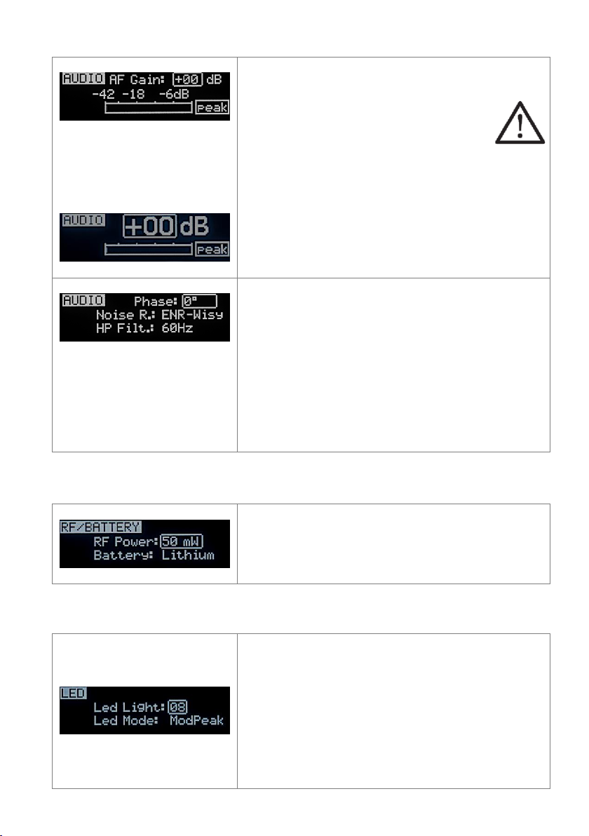
“AF Gain” setup to tune audio input sensitivity:
To help proper audio gain setting, an audio
bar is supplied with peak hold bar)
indicating the headroom to audio peak
(0 dB).
AF gain is shown with 2 different unit of
measurements dB (gain in dB of MTP41 amplifiers) or
in dBu peak.
Using quick gain setup buttons (<GAIN>), it is possible to
enter quickly in the audio gain menu. Note that the menu
has a different layout (see the side image)
The second <AUDIO> menu allows to set:
- audio phase (0° or 180°)
-Noise reduction:
ENR: designed for maximum noise reduction
ENC: designed for maximum audio fidelity (use
this in case of special vocal application or to
remote instruments)
-High Pass Filter: applies different audio HP filter:
Flat /60Hz /80Hz/120Hz /170Hz /250Hz /400Hz.
Use the selector to change values (<+/->) and <click> to
confirm.
RF power can be setup to 50 mW or 10 mW.
Use the Battery menu to select the type of battery used.
MTP41 support Alkaline/NiMH/Lithium battery type.
Use the selector to change values (<+/->) and <click> to
confirm.
Led Light allows to change the brightness of the front led
(0÷16) .
Led Mode:
- ModPeak: allows to enable modulation peak LED on
front led (become RED when audio get close to
saturation)
- none: allows to disable modulation peak LED on front
led
- PTT: allows to enable RED color on front led when PTT
button is pushed.
<RF/BATTERY> menu
This menu can be entered by scrolling selector.
<LED> menu
This menu can be entered by scrolling selector.
Page 8
<MIC> menu
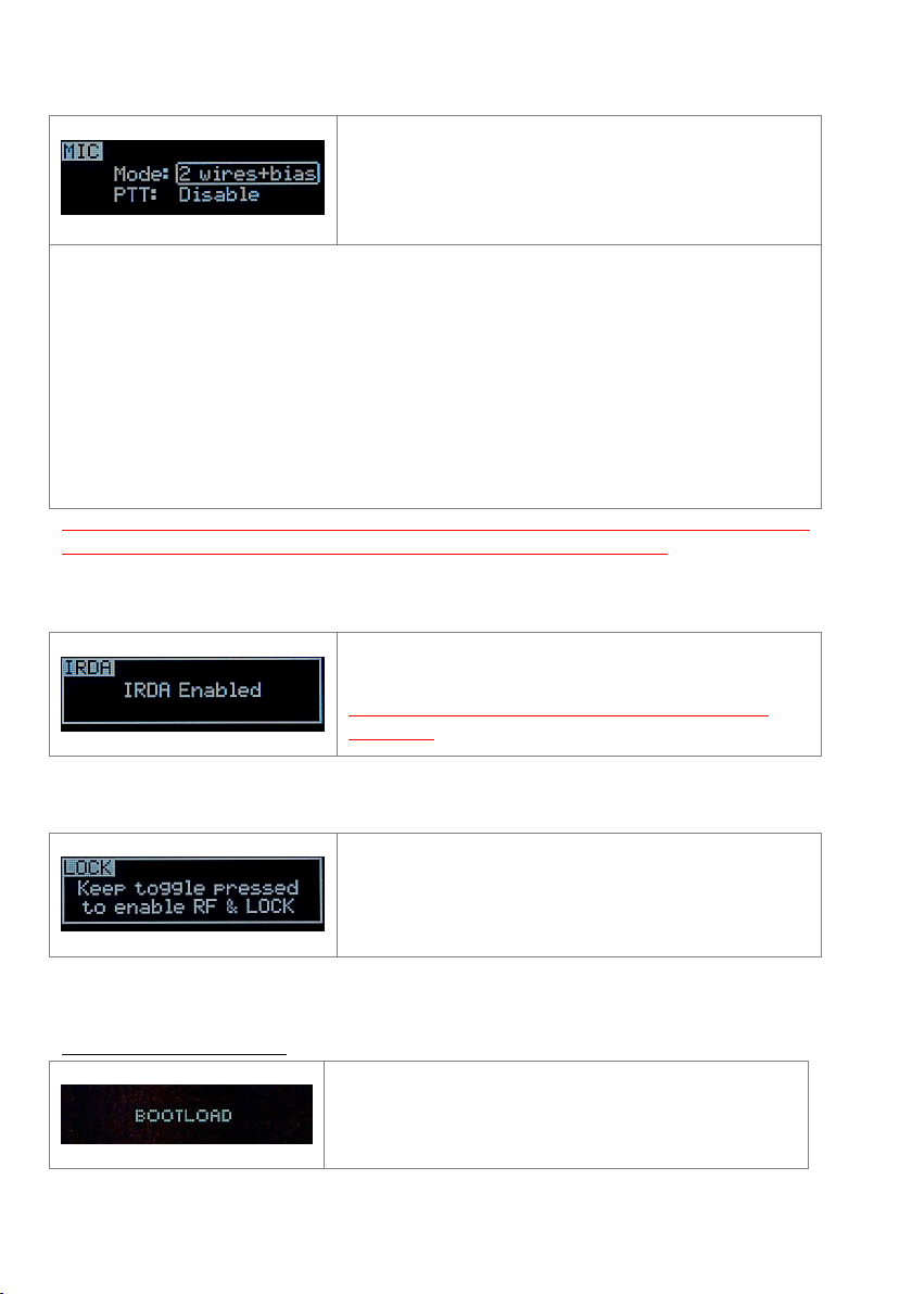
Mode: Following Mic mode can be setup (for LEMO
option)
-2 wires: (PTT is possible) for external audio input
-2 wires + bias: (PTT is possible) for most 2 wires MIC
-3 wires: (no PTT) for most 3 wires MIC
PTT setting defines how and what information the transmitter has to send in normal use or
when the PTT button is pushed.
- Disable: when the PTT button is pushed, nothing happen. (the transmitter sends AF+Tone
squelch)
- Normal: when the PTT button is pushed, the transmitter send a different RF signal.
According to the receiver configuration the audio can be enabled/disable on LINE (and/or
COM).
- Muting: the transmitter doesn’t send the audio. The voice is cut, it doesn’t enter to the
microphone
- No Data: the transmitter sends neither tone squelch nor battery data.
Use the selector to change values (<+/->) and <click> to confirm.
While is this menu MIC can be connected to IRDA for
setup or firmware upgrades.
NOTE: while in this menu display is not automatically
turned off.
Long pressing (2 sec.) selector button (click) it locks
MTP41 in transmission mode.
To unlock, long pressing (2 sec.) selector button again.
Device is forced in bootloader mode to allow FIRMWARE
UPDATE.
This menu can be entered by scrolling selector.
NOTE: For DPA option (2 pin microdot audio connector), even if the MIC mode menu allows to
set one of the 5 MIC modes, only 2 wires or 2 wires+bias mode are possible.
<IRDA> menu
This menu can be entered by scrolling selector.
<LOCK> menu
This menu can be entered by scrolling selector.
<BOOTLOAD> menu
This menu can be entered only turning on the transmitter while pushing at the same time both
quick channel setup buttons (<ch> & <gain>).
Page 9
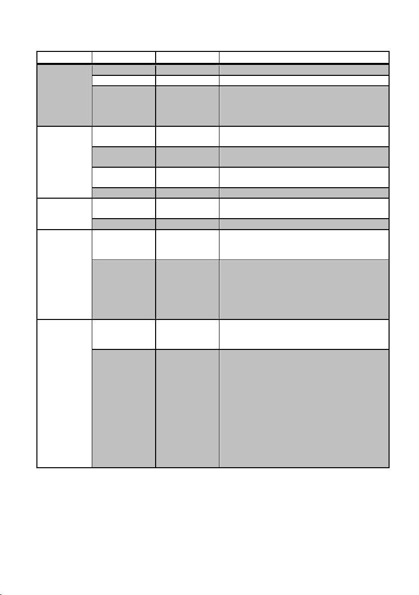
The following table sums up which parameters can be set and the related range settings.
MENU
PARAMETER
MEANING
RANGE SETTINGS
TUNING
CH
Channel
0 ÷ 59
GR
Group
0 ÷ 39 + SYNC GROUP
Freq
Frequency
depends on the MTP41 Model:
1 470-640
2 566-798
3 510-698
AUDIO
AF In Gain
Gain of the
audio signal
-60dB ÷ 40dB step of 1 dB
Phase
Audio signal
phase
0° or 180°
Noise R.
Noise reduction
ENR: Wisycom Extended-NR,noise optimized
ENC: Wisycom Extended-NC,voice optimized
HP Filt.
High Pass filter
Flat/60/80/120/170/250/400 Hz
RF/BATTERY
RF Power
RF Power
50 mW or
10 mW
Battery
Battery type
Alkaline / NiMH / Lithium
LED
Led Light
Power switch
green
brightness
0 ÷ 16
Led Mode
It defines when
the power
switch led (see
Fig. 3) has to
become RED
None: never
ModPeak: when audio get close to saturation
PTT: when the PTT button is pushed
MIC
Mode
MIC type
’2 wires’
‘2 wires + bias’
‘3 wires’
PTT Mode
It defines how
and what
information the
transmitter has
to send
Disable:when the PTT button is pushed, nothing
happen. (the transmitter sends AF+Tone
squelch)
Normal: when the PTT button is pushed, the
transmitter send a different RF signal. According
to the receiver configuration the audio can be
enabled/disable on LINE (and/or COM).
Muting: the transmitter doesn’t send the audio.
The voice is cut, it doesn’t enter to the
microphone
No Data: the transmitter sends neither tone
squelch nor battery data.
Page 10
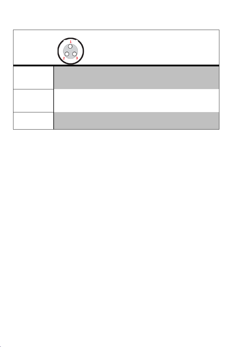
MIC Mode setting (only for LEMO option):
MIC Mode:
Pin out
Gain
PTT
Led Mode
’2 wires’:
1=GND
3=AF
-60/40 dB
Disable
Normal
Muting
No data
None
Mod. Peak
PTT
‘2 wires + bias’:
1=GND
3=AF+5.5V
-60/40 dB
Disable
Normal
Muting
No data
None
Mod. peak
PTT
‘3 wires’:
1=GND
2=5.5V
3=AF
-60/40 dB
Disable
No data
None
Mod. peak
Page 11
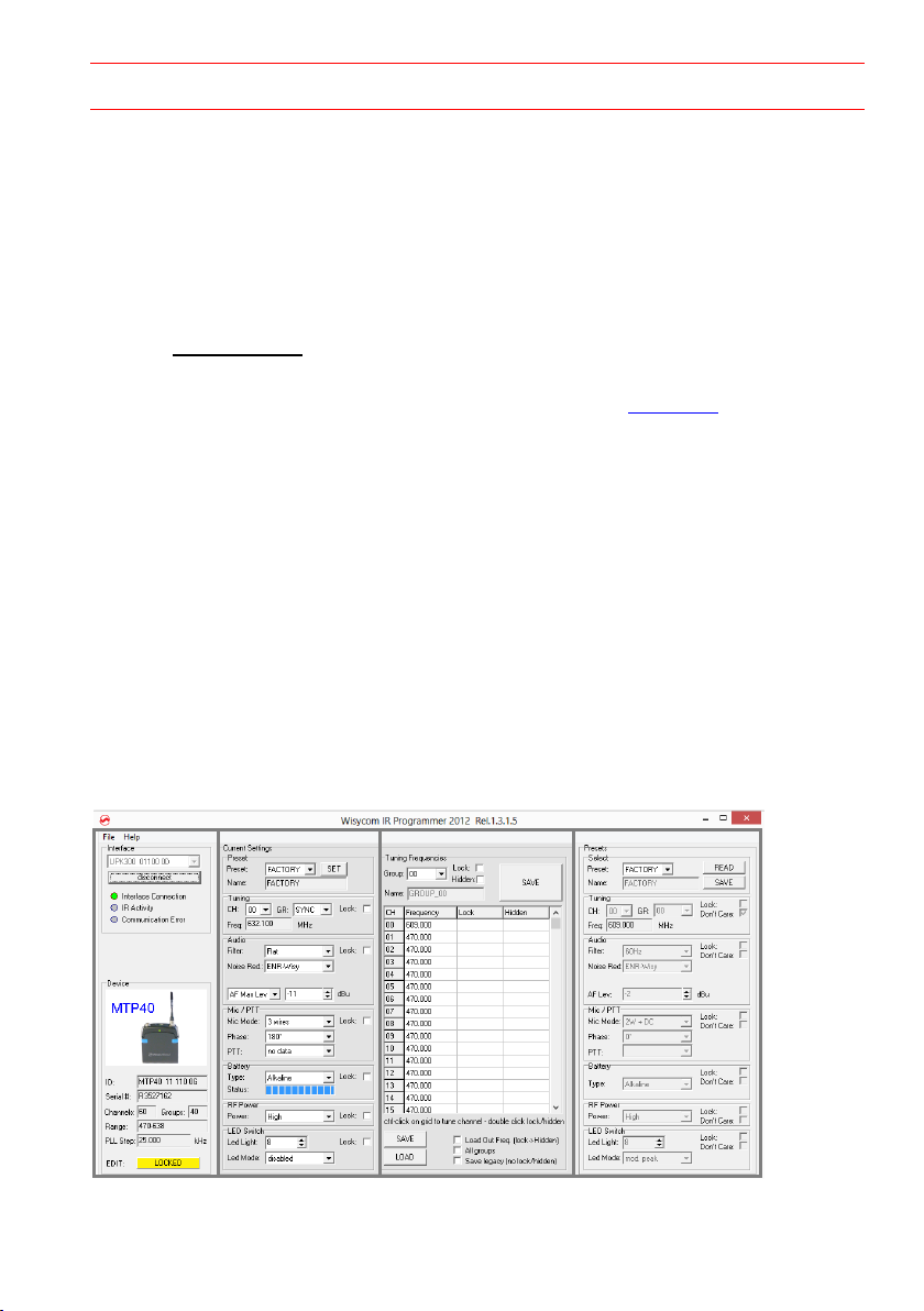
WISYCOM IR PROGRAMMER (VER. 1.3.2.0 AND ABOVE)
❶
❷
❸
❹
Wisycom IR Programmer allows to read, modify and update the MTP41 device configuration.
It is necessary to
install Wisycom IR Programmer (version 1.3.2.0 or above)
WARNING: If it is the first installation and Wisycom USB driver has not already
installed in the PC, install the USB driver (run C:\Program Files
(x86)\Wisycom\MTP&MTH Infrared Programmer (TX)\Drivers\ DriverInstaller.exe)
connected the programmer UPK300 or the receiver MRK950/MRK960 to the PC thru
USB connection
run the program
enable the IRDA communication on the transmitter (see IRDA menu)
NOTE: Wisycom IR Programmer doesn’t work whit MRK950/MRK960 if it is connected to the
PC using an ethernet cable.
The Wisycom IR Programmer’s window is divided in 4 parts (see Fig. 5):
❶Interface and Device panel contains all the major information of the connected device
❷Current Settings panel shows the current configuration. Thanks the PRESET panel, a
previous saved configuration can be chosen and loaded like current setting.
❸Tuning Frequencies panel allows to handle Groups, Channels and Frequencies
❹Presets panel allows to read, change and save different configurations
Figure 5: Wisycom IR Programmer’s window
Page 12

10 different configurations are available:
• FACTORY configuration is a locked configuration: no parameter can be changed.
USER configuration is the only configuration that can be saved using the OLED display (see
<PRESET> menu). Note: It is not possible to change the name of this configuration.
Other 8 configurations where the user can change both the name and the values of all
parameters.
INTERFACE AND DEVICE PANEL
At the beginning, the program checks which IR devices are detected and they appears on the
Interface panel.
The user has to select the device and push <connect> button in order to open the
communication with the IR device. A picture on the top in the Interface panel help the user in
this selection showing the type of devices detected. During this process the “IR activity” led
blinks to indicate that the program wait connection’s answer from the IR device.
A successful connection is signaled with the “interface connection” green led, while a failed
connection is signaled with the “communication error” led.
Once a supported device is found, the software automatically reads all the data related to the
remote configuration, as well as the frequencies that are pre-programmed.
Firstly, in order to avoid unwanted operation, no parameters can be changes and the EDIT
button, presents on the bottom of Device panel, is yellow and set to LOCKED state. Pushing
the EDIT button, it becomes grey and sets to UNLOCKED state to indicate that the
configurations can be modified.
CURRENT SETTINGS PANEL
In the Current Settings panel the user can
with Preset panel → load one of the 10 available configurations
with other panels → modify all the configuration’s parameters (the same that are
changeable in the OLED display). Each parameter can be locked clicking the related
lock button, so the set value can not be changed next using the OLED display.
ATTENTION: All the modifies applied to the Current Settings panel are instantaneous: they are
applied directly to the device and save in its memory but no saved in the preset configuration.
Page 13
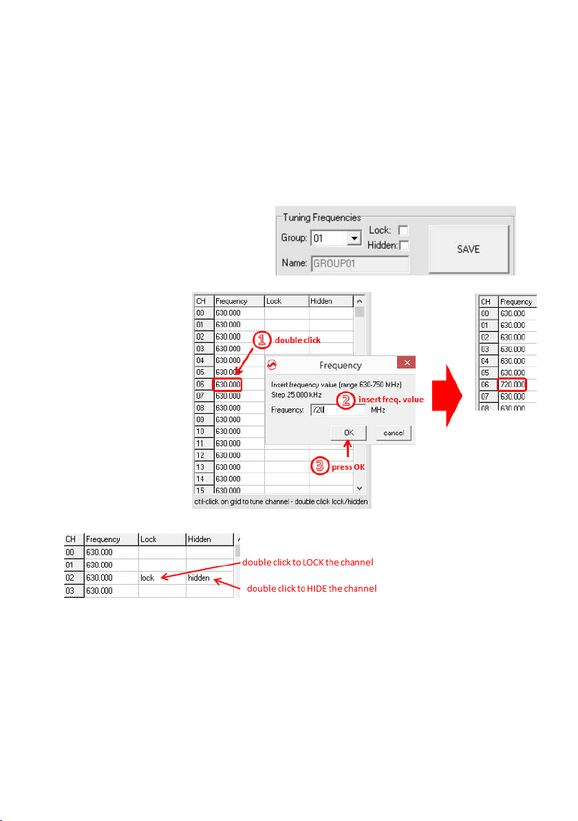
TUNING FREQUENCIES PANEL
With the Tuning Frequencies panel the user can select a frequencies group (0÷39) and for each
one execute the following operations:
- modify the Group’s Name
- lock and/or hidden the group
- for each channel (0 ÷59) of the selected group: change the frequency value and the
related status (locked/hidden) (in the center grid frequency)
The SAVE button, at the top of the
panel, save the changes of the group
selected (name group, lock/hidden
group).
To change a frequency
value for a specific
channel: double click
on the grid frequency
panel (row=channel’s
number), insert the
new frequency value
and press OK button.
To lock/hide a specific
channel, double click on the
grid frequency panel.
NOTE: keeping pressed the CTRL button on the keyboard and clicking the wanted
channel/group shown on the frequencies grid, the tuning process is executed. It is equivalent
to configure the Tuning in the Current Settings panel but it is easier. The device is re-tuned
immediately, so be sure that the RF power is turned off while changing frequencies with other
RF systems in use around you!
If the currently tuned channel is on the same group that is listed on the grid, the background
color of the related cell (channel) on the grid becomes yellow.
Page 14
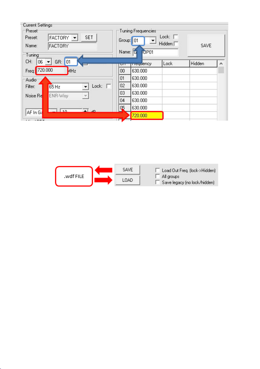
Using the LOAD/SAVE button, at the bottom of the panel, it is possible to load/save the
frequencies for the selected group from/to a .wdf file. To save the frequencies of all the groups
click to the related button above. The legacy option save the channels without the hidden/lock
info.
Page 15
PRESETS PANEL
PRESETS:
NAME*
LOCK/DON’T CARE
PARAMETERS
VALUE
FACTORY
USER
√
OTHERS √ √
√
The Preset panel allows to manage all the 10s available configurations.
For each configuration it is possible to set the name and all the parameters value except for
FACTORY and USER configurations (see table below).
√=change is allowed
* Be careful to write a meaningful name for the preset because the name will appear on the
settings list of the device menu! Please, avoid empty names.
If a parameter is “locked”, it cannot be modified by device menu (using OLED display), while if
“don’t care” propriety is active, when the user load the configuration, the parameter’s value
doesn’t changed.
ATTENTION: Changes are applied only after a “save” action.
NOTE: “a trick” In case of the user have a locked parameter and he is in great need for modify
it, he can save the configuration to USER configuration by OLED (see PRESET menu) and then
load the USER configuration (in this way all the parameters have the lock propriety disable and
the user can modify all the parameters).
FILE MENU
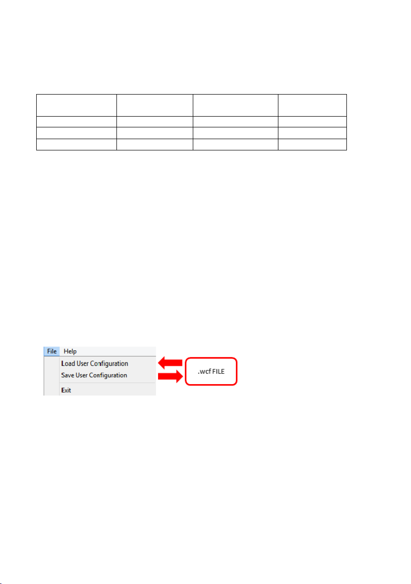
Save a .wcf file
With an infrared device correctly connected, select File->Save User Configuration and select
the destination file.
Load a .wcf file
To load a user configuration select File->Load User Configuration and select a previously saved
data file; a form will be shown, where it's possible to select which data has to be restored and
which skipped. This allow the user to load a particular configuration while keeping other data.
Using a file menu at the top left of
the panel it is possible to load/save
all the configuration values of the
device to/from a .wcf file (Wisycom
Configuration File).
Page 16

TECHNICAL SPECIFICATIONS
Switchable
channels
2400 allocated by 40 groups of 60 channels (in specific frequency range), quickly
selectable with dedicated buttons
Switching
window
Up to 90 MHz, depending on band (see below code table)
Frequencies
Quartz PLL frequency synthesizer circuit (25 kHz step)
Frequency
stability
▪ ± 2,5 ppm (in the rated temperature range)
▪ ± 2.5 kHz (in the rated temperature range)
Temp.range
-10 ÷ +55 °C
Max RF power
▪ 50 mW (ERP) when high power selected
▪ 10 mW (ERP) when low power selected
Spurious
emissions
< 2 nW
Modulation
wideband FM with pre-emphasis
Nominal
deviation
±40 kHz (Peak deviation = ±56 kHz)
Telemetry
feature
MTP41 transmits also a digitally modulated sub-carrier, suitable for:
▪tone-squelch operating
▪ remote battery monitoring
▪ optional PTT (push to talk) operation
AF input
connector
LEMO option
Configurable on ‘mic’ display menu in 3 options:
▪ ’2 wires’:
▪ ‘2 wires + bias’:
▪ ‘3 wires:
gain selectable -60 ÷ +40 (-54 dBu ÷ +26 dBu peak), no bias voltage
gain selectable -60 ÷ +40 (-54 dBu ÷ +6 dBu peak), 5.5 V on 4k7 bias supply
gain selectable -60 ÷ +40 (-54 dBu ÷ +26 dBu peak)
AF input level
100 dB adjustable range from -60 dBu (775 uV) to 26 dBu (15.5 V) at peak deviation (1
kHz), adjustable in 1 dB steps
Max. input level
+26 dBu (15.5 V) at clipping, +20 dBu (7.75 V) at nominal level
Noise-Reduction
ENR (Wisycom Extended-NR), with independent Attack- and Recovery-time, noise
optimized
ENC (Wisycom Extended-NC), with independent Attack- and Recovery-time, voice
optimized & with reduced pre-emphasys
AF bandwidth
▪ 45 Hz ÷ 21 KHz (3dB)
▪ 55 Hz ÷ 20 KHz (1dB)
Distortion
< 0.3 % (0.15 % typ.)
Signal-to-noise
ratio
▪ typ. 115 dB (A)
rms
with 40 kHz deviation
▪ typ. 121 dB (A)
rms
with 56 kHz deviation
Led
Led indication with bicolor led (red & green) on wireless power switch:
▪ Wireless transmission status:
GREEN on/off
▪ Battery lifetime status: GREEN - steady (> 25%)
- slowly blinking (< 25%) - quickly blinking (<12%)
▪ Modulation peek (if activated): RED
▪ Ptt status: RED if active
Display
High contrast OLED (Organic light-emitting diode) bicolor display (96 x 36 pixels)
8 step battery lifetime indication: 7 bars (100%-87%-75%-63-50%-38%-25%) and “empty
bar” quickly blinking (12% remaining)
PTT function
Pin 3 of the AF connector can be setup to an external push button
Power supply
1 AA size batteries (Alkaline, rechargeable NiMH, Lithium)
MTP41 Battery
life
▪ approx. 11 hours @ 50mW continuous working Lithium
▪ approx. 8 hours @ 50mW continuous working with NiMH
▪ approx. 4.5 hours @ 50mW continuous working with Alkaline
Page 17
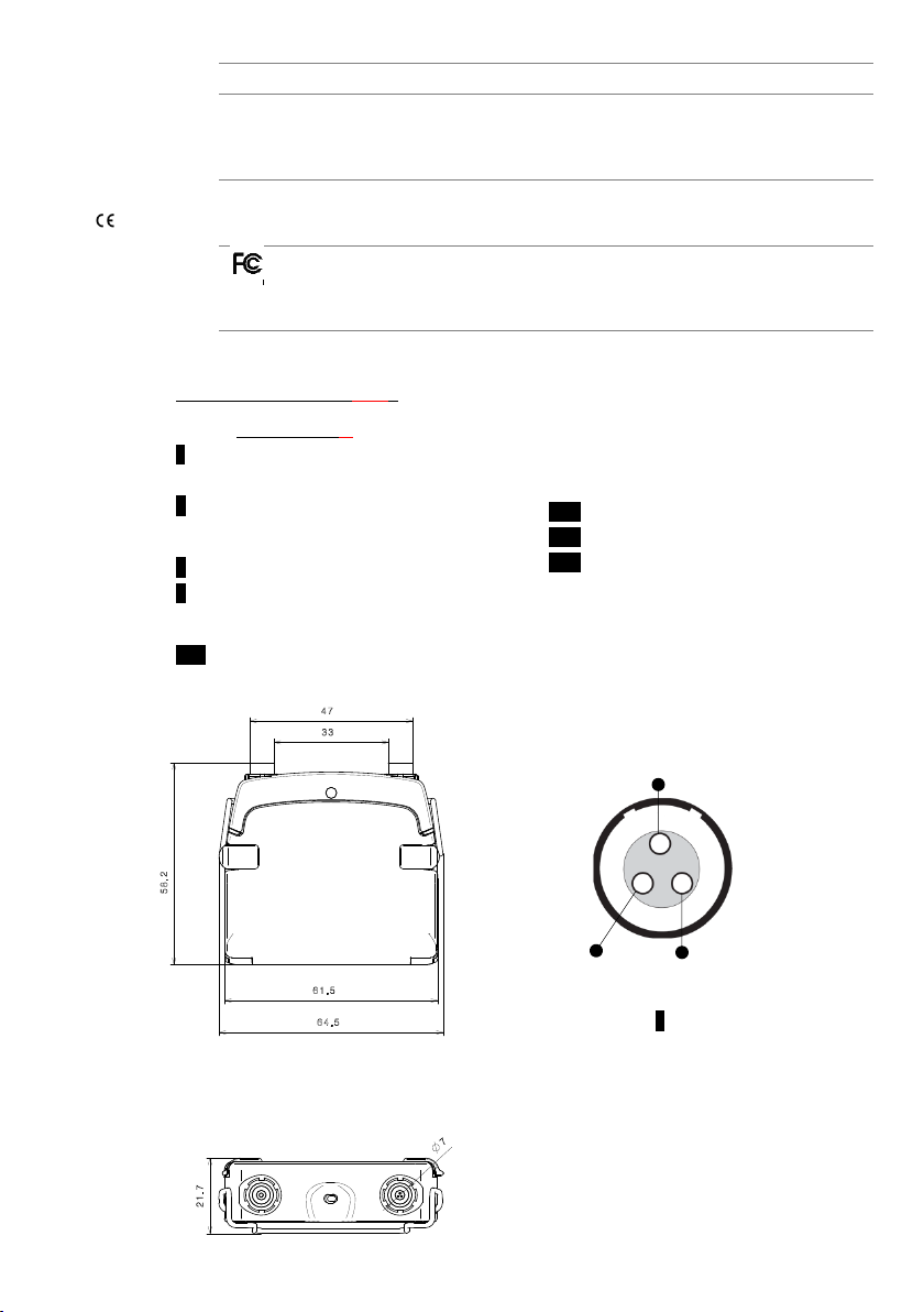
Dimensions
58.2 x 64.5 x 21.7 mm (Height-Width-Depth)
Weight
Approx. 80 g. without batteries (120g with batt.)
In compliance with
Europe
EMC: EN 301489-1/-9
Radio: EN 300422-1/-2
Safety: EN 600065
USA
PART 74
FCC-ID: POUMTP41
Limited to 698 MHz
Note: MTP41 transmitter complies with ETS 300 422
▪ FREQUENCY RANGE (-Z)
1 470-640 MHz
2 566-798 MHz
3 510-698 MHz
GND
5.5V
AF
AF + 5.5V (2 wires)
Option L Lemo Conn.
OPTION CODE MTP41-X-YZ :
▪ AUDIO CONNECTOR (-X)
L 3 PIN LEMO CONNECTOR
(use FVB.00.003.NLN on Mic)
D 2 PIN MICRODOT CONNECTOR
▪ COLOR (-Y)
B body color "matt black"
P body color “titanium gray” (ceramic coating)
▪ OTHER OPTIONS (-O)
ADT Compatible with dummy batt. pack
Ex. MTP41-L-B1 is 3 pins LEMO connector , matt black color and 470-640 Mhz frequency range
(3 wires)
Page 18

MANUFACTURER DECLARATIONS
In compliance with the following requirements
RoHS Directive (2002/95/EC)
WEEE Directive (2002/96/EC)
Please dispose of the diversity transmitter at the end of its operational
lifetime by taking it to your local collection point or recycling center for
such equipment
Battery Directive (2006/66/EC)
The supplier batteries or rechargeable batteries can be recycled. Please
dispose of them as special waste or return them to your specialist dealer. In
order to protect the environment, only dispose of exhausted batteries.
FCC Conformity
This device complies with Part 74 of the FCC Rules. Operation is subject to the following two
conditions:
(1) This device may not cause harmful interference, and
(2) This device must accept any interference received, including interference that may cause
undesired operations.
Changes or modification not expressly approved by the party responsible for compliance could
void the user’s authority to operate the equipment.
FCC ID can be found inside the battery compartment.
FCC ID: POUMTP41
Page 19
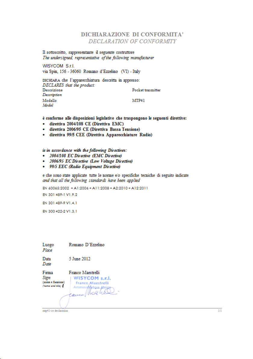
EC Declaration of Conformity
Page 20
ITALY ONLY
Obblighi di informazione agli utilizzatori
ai sensi dell’art. 13 del Decreto Legislativo 25 luglio 2005, n. 151 “Attuazione delle Direttive 2002/95/CE,
2002/96/CE e 2003/108/CE, relative alla riduzione dell’uso di sostanze pericolose nelle apparecchiature
elettriche ed elettroniche, nonché allo smaltimento dei rifiuti”
Smaltimento di apparecchiature elettriche ed elettroniche di tipo professionale
Il simbolo del cassonetto barrato riportato sull’apparecchiatura o sulla sua confezione
indica che il prodotto alla fine della propria vita utile deve essere raccolto separatamente
dagli altri rifiuti.
La raccolta differenziata della presente apparecchiatura giunta a fine vita è organizzata e
gestita dal produttore. L’utente che vorrà disfarsi della presente apparecchiatura dovrà
quindi contattare il produttore e seguire il sistema che questo ha adottato per consentire
la raccolta separata dell’apparecchiatura giunta a fine vita.
L’adeguata raccolta differenziata per l’avvio successivo dell’apparecchiatura dismessa al riciclaggio, al
trattamento e allo smaltimento ambientalmente compatibile contribuisce ad evitare possibili effetti
negativi sull’ambiente e sulla salute e favorisce il reimpiego e/o riciclo dei materiali di cui è composta
l’apparecchiatura.
Lo smaltimento abusivo del prodotto da parte del detentore comporta l’applicazione delle sanzioni am-
ministrative previste dalla normativa vigente.
Smaltimento batterie usate
Questo prodotto può contenere batterie. Questo simbolo apposto sulle batterie significa
che non possono essere smaltite insieme a normali rifiuti domestici, bensì devono essere
depositate negli appositi punti di raccolta delle batterie.
Iscrizione al Registro A.E.E. n. IT09100000006319
.
WISYCOM srl
Via Spin 156 I-36060 Romano d’Ezzelino Italy
Tel. +39 -0424 -382605 Fax +39 - 0424 - 382733
www.wisycom.com e-mail: [email protected]
 Loading...