

Page 1
ADFA
Ultra-Wideband Active Antenna
with remote controlled filter bank
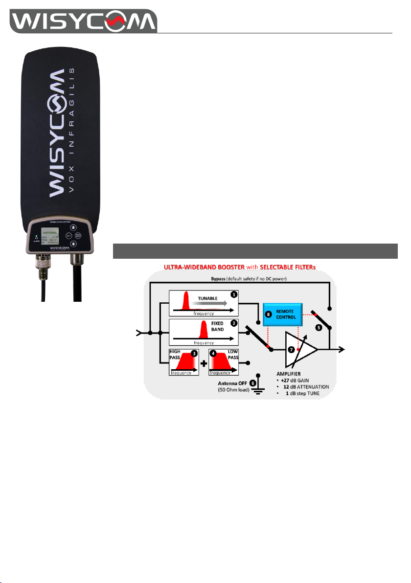
❶ Tunable filter 410-730 (40 MHz wide)
❷ Fixed band saw filter: 940-960 MHz (Usa) or 1240-1260 (Japan) or 470-700MHz &
960-1160MHz (4G-STOP)
❸ ❹ High pass filter (410/470/510 MHz) and low pass filter (600/700/810 MHz)
CASCADE (9 bandpass combinations)
❺ Bypass line for full band reception (active mode if no DC power for safety)
❻ Antenna off for zone control
❼ Gain control from -12 dB to 27 dB
❽ Remote control with a data link running on coaxial cable
ADFA is an omnidirectional antenna with a unique design to achieve
an ultra-wideband of 430 -1160 MHz.
ADFA integrate a unique bank of filters along with a low noise
amplifier.
Filters and gain can be easily setup locally thru a 4 key navigation
buttons and a TFT display or remotely with a data connection on the
same RF coaxial cable.
Using the latest Wisycom filter technology, ADFA gives a full control of
RF zones and allows to build flexible and remote controllable antenna
systems.
The feeding line is integrated on the PCB (for mechanical robustness)
and all the electronic and mounting base are made by solid metal with
waterproof gasketing.
BLOCK DIAGR A M
pg. 1
Page 2
ADFA
Ultra-Wideband Active Antenna
with remote controlled filter bank
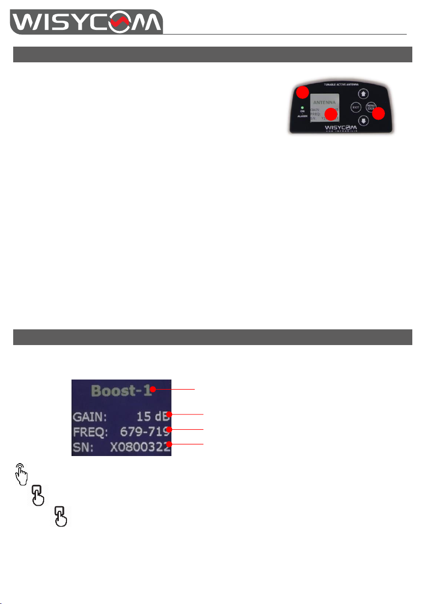
NAME of ANTENNA
Gain
Frequency range
Serial Number
2 1 3
SETUP CONT RO L
1) Simple operation with 4 buttons to quickly monitor
and setup the antenna booster and filters through
the user menu.
2) Signaling LED multicolor:
o White: when the unit is in bootloader
mode during the firmware upgrade
o Orange: booster bypassed, antenna becomes passive
o Green: active booster with gain between -12 ÷ 14 dB (low consumption
approx. 65mA@12V)
o Blue: active booster with gain between 15 ÷ 27 dB
(consumption approx. 110mA@12V)
o Red: fast blinking (when blinking function is activated by Manager or by
MAT/SPL for easily recognizing of antenna)
o Red: fixed, alarm (type of alarm is shown on the display)
o OFF: antenna OFF mode or LED disable by settings
3) TFT – transflective (176 x 176 pixels, RGB)
ME NU STRUCT U R E AND NAVIGA T ION
STATUS menu This is the first menu displayed after power up and provides access to submenus and
displays a summary of antenna settings.
Push MENU/SAVE to enter in the menu
Use the arrows to navigate the menu and edit the parameters
Keep pushing MENU/SAVE for 2 seconds to save
Confirm the new setup value within 5 sec. by pressing one more time on the MENU/SAVE
button. Without any confirmation within 5 sec. the modification is cancelled.
pg. 2
Page 3

ADFA
Ultra-Wideband Active Antenna
with remote controlled filter bank
MENU
SUBMENU
SETTINGS
example
Gain
OFF/ Bypass/ -12dB to 27dB
2dB
Filter
4G-STOP
(only F6 version)
470-1160MHz
470-700 & 960-1160MHz
WB (Wide Band)
(F1/F2 version)
High pass filter (i.e.410/470/510 MHz) and
Low pass filter (i.e.600/700/810 MHz)
470-600 MHz
NB (Narrow Band)
940-960 MHz (Usa) or
823-832 MHz
940-960 MHz
Tunable
410 ÷ 730 MHz (40MHz) @1MHz step
410-450 MHz
Freq
Frequency range of selected filter
Settings
Display
Timeout
from 5s to 240s
20s
Brightless
from 1 to 10
5
Color
white/black
white Rotate
0/180
0
Led
ON/OFF
ON
Boost
ON/OFF
Data
ON /OFF
Info Model
Model of antenna
ADFA-B-F6
Name
Name of antenna (max 8 characters)
ANT-A Z1
SN
Serial number
X1300045
FW
Firmware/Application/Boot Ver
HW
Option
B
Main rev.
1
Filter rev.
1
Supply
12.0 V
Typical attenuation of most common coaxial cable (30m / 100 ft.)
Cable type
Diameter mm (in)
Attenuation @ 400 MHz
Attenuation @ 900 MHz
RG 58 C/U
4.95 (1.9)
9.6 dB
10.4 dB
RG 213 /U
10.3 (4)
3.9 dB
6.6 dB
RG 218 /U
22.1 (8.6)
2.1 dB
4.2 dB
Cellflex - ¼” foam
8.8 (3.4)
2.5 dB
3.9 dB
Configure filter setting according to the frequency range in use.
Configure gain setting according to the loss of the cable used (see below typical attenuation
table).
When GAIN is set to OFF (by pass mode) internal filter is disabled and the antenna is working in
430÷1160 MHz range.
For more details about antenna settings see the below menu:
pg. 3
Page 4
ADFA
Ultra-Wideband Active Antenna
with remote controlled filter bank
ADFA-<Connector>-<FilterOption>
<Connector>
B BNC female
N N female
<FilterOption>: Tunable Filter Selectable Filter Fixed Filter:
F1 TUN:410-730MHz HP: 410/470/510 MHz + LP: 600/700/810 MHz 940 ÷ 960 MHz (Europe/Usa)
F2 TUN:410-730MHz HP: 470/520/550 MHz + LP: 617/663/698 MHz 940 ÷ 960 MHz (Europe/Usa)
F6 TUN:410-730MHz Narrow Band 823-832MHz 470-700 & 960-1160MHz (4G-STOP)
Wisycom Srl - Via Tiepolo, 7/E - 35019 Tombolo (PD) - Italy
tel. +39 0424 382605 fax. +39 0424 382733 - www.wisycom.com - e-mail: [email protected]
SPECIFICATI O NS
ANTENNA
• Gain: 3dBi typical
• Bandwidth: 430÷1160 MHz
• Polarization: vertical
BOOS TER
• Control: display menu or remote thru coaxial cable (thru MAT244/MAT288/SPL2208/SPL2216)
• Gain: -12÷27 dB typical (1 dB step selection)
• Bandwidth: from 430MHz up to 1160 MHz (depending on the variants)
• Gain flatness: +/-1 dB
• Powering: +12 Vdc/65mA (green led, up to about 15dB of gain),
+12 Vdc/110mA (blue led, more than about 15dB of gain)
• Full bandwidth Bypass (0.8dB attenuation) and RF OFF function
FILTE R
• Tunable: 410* ÷ 730 MHz (UHF), 40MHz of BW
• Fixed:
o 940 ÷ 960 MHz (for USA) or
o 470-700MHz & 960-1160MHz (4G-STOP)
• Selectable band pass filter: HP 410/470/510 MHz, LP 600/700/810 MHz (other see filter option)
MECHA NICAL
• Connectors: BNC-F (LFA-B), N-F (LFA-N)
• Display: TFT – transflective (176 x 176 pixels, RGB)
• Body Material: Epoxy fiberglass with skeletal design
• Finishing: Black matte textured weather resistance coating
• Mounting: 5/4" & 3/8“ thread (metal support and mounting base)
• Weight: 315 g (BNC), 365 g (N)
• Size: 305 x 111 x 28 mm (H x W x D)
VA RIANTS
pg. 4
 Loading...