

Page 1
43
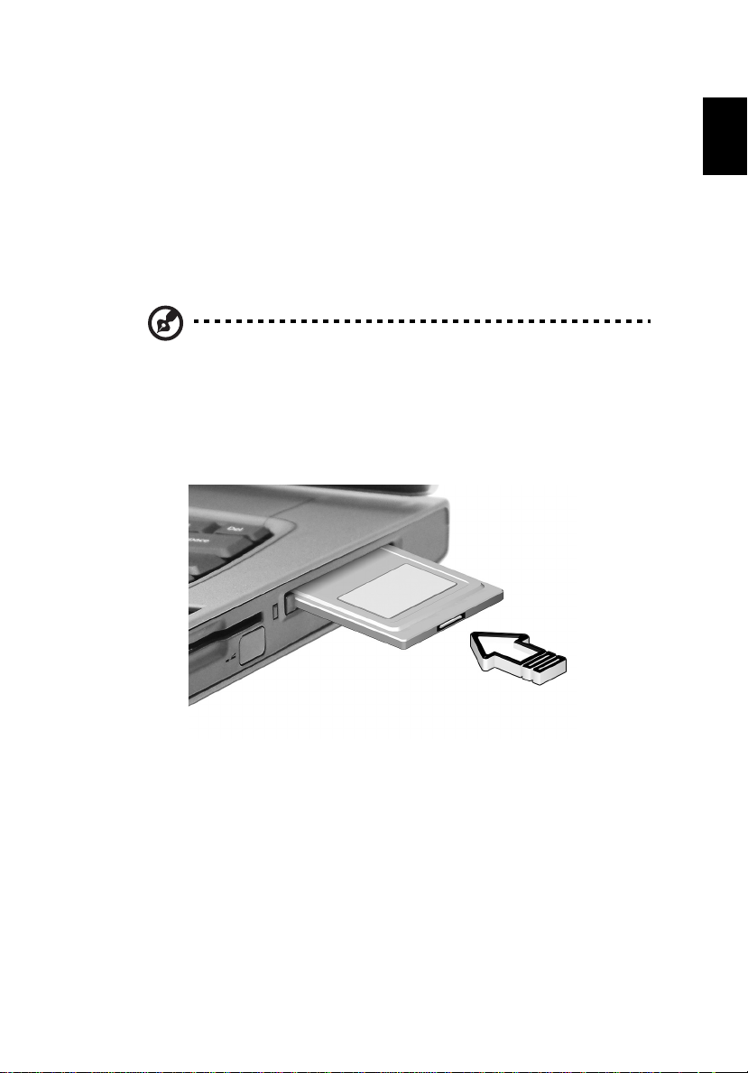
PC Card slot
The Type II CardBus PC Card slot found on the right side of the
computer accepts credit-card-sized cards that enhance the usability
and expandability of the co mpute r. T hese c ards sho uld hav e a PC Ca rd
logo on them.
PC Cards (formerly PCMCIA) are add-on cards for portable computers,
giving you expansion possibilities long afforded by desktop PCs.
CardBus improves on the 16-bit PC card technology by expanding the
bandwidth to 32 bits.
Note: Refer to your card’s manual for details on how to install
and use the card and its functions.
Inserting a PC Card
Insert the card into the lower slot and make the proper connections
(e.g., network cable), if necessary. See your card manual for details.
English
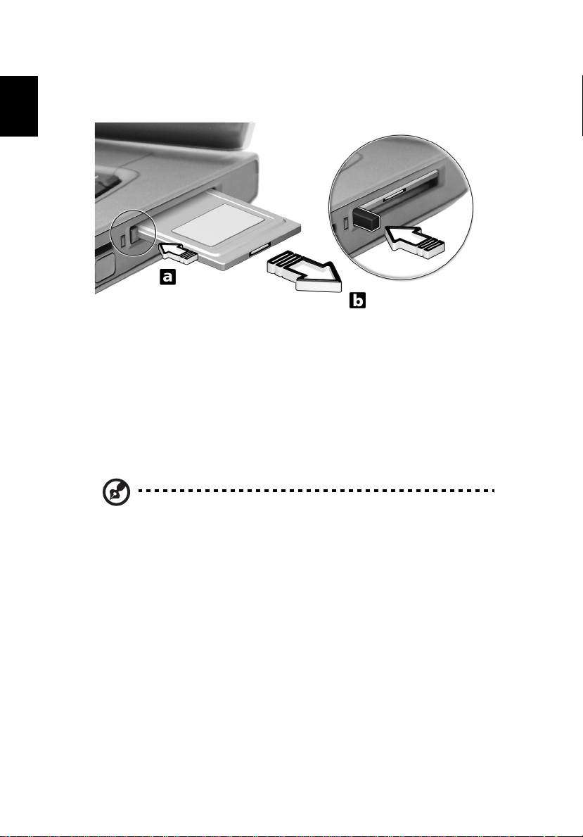
Ejecting a PC Card
Before ejecting a PC Card:
1 Exit the application using the card.
2 Left-click on the Safely Remove Hardware icon on the taskbar and
click on the PC Card item. Click OK to confirm.
Page 2
2 Customizing my computer44
3 Press the slot eject button (1) to pop out the eject button; then
press it again (1) to eject the card (2).
English
Upgrade options
Your computer delivers superior power and performance. However,
some users and the applications they use may demand more. This
computer allows you to upgrade key components when you need
increased performance.
Note: Contact your authorized dealer if you decide t o pe r f or m a
key component upgrade.
Memory upgrade
Memory is expandable t o 2 GB, emp loying 2 56M B/512MB /1GB SDRA M
modules. Two DDR DIMM slots. The computer supports shadow RAM.
There are two memory slots on your computer, one of which is
occupied by standard memory. You can upgrade memory by installing
a memory module into the available slot, or replacing the standard
memory with a higher-capacity memory module.
Page 3
45
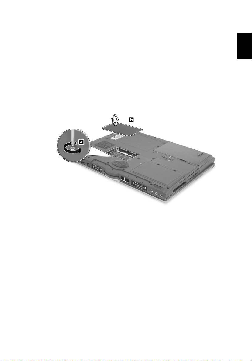
Installing memory
Follow these steps to install memory:
1 Turn off the computer, unplug the AC adapter (if connected) and
remove the battery pack. Then turn the computer over to access
its base.
2 Remove the screw from the memory cover (a); then lift up and
remove the memory cover (b).
English
Page 4
2 Customizing my computer46
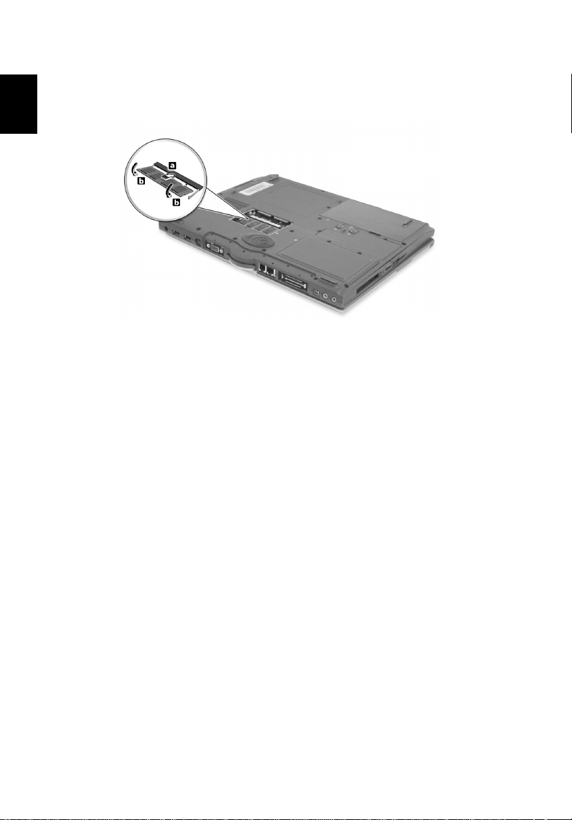
3 Insert the memory module d iago nall y into the slo t (1), the n ge ntly
press it down until it clicks into place (2).
English
4 Replace the memory cover and secure it with the screw.
The computer automatically detects and reconfigures the total
memory size.
Page 5
47
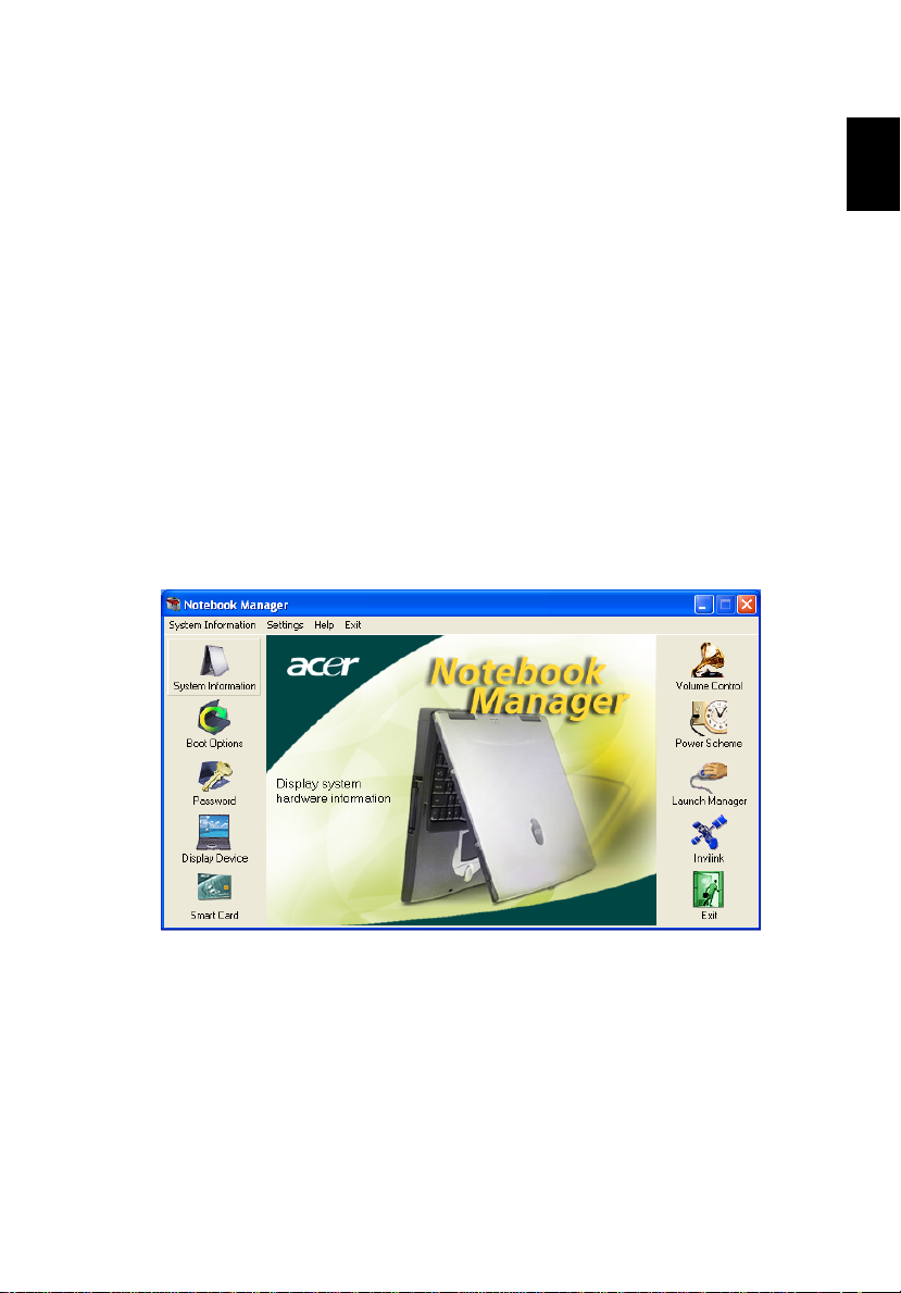
Using system utilities
Notebook Manager
The computer has a built-in system setup program called Notebook
Manager. The Windows-based Notebook Manager allows you to set
passwords, the startup sequence of the drives, and power
management settings. It also shows current hardware configurations.
To start the Notebook Manager, press Fn-F2 or follow these steps:
1 Click on Start, All Programs, then Notebook Manager.
2 Select the Notebook Manager application to run the program.
Click on Help for more information.
English
Page 6
2 Customizing my computer48
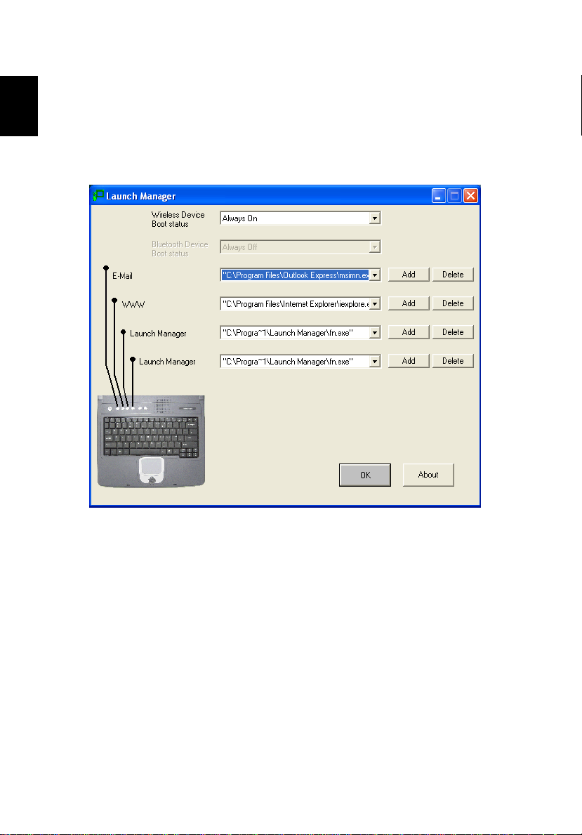
Launch Manager
There are six Launch Keys located above the keyboard. The Wireless
English
button is not programmable. Launch Manager only allows you to set
the other five Launch Keys. See “Launch Keys” on page 23 for more
information.
You can access the Launch Manager by clicking on Start, All
Programs, and then Launch Manager to start the application.
Page 7
49
BIOS Utility
The BIOS Utility is a hardware configuration program built into your
computer’s BIOS (basic input/output system).
Your computer is already properly configured and optimized, and you
do not need to run this utility. However, if you encounter
configuration problems, you may need to run it.
T o activa te the BIOS Utility, press F2 during the POST (power-on selftest) while the TravelMate logo is being displayed.
English
Navigating the BIOS Utility
These are the menu options: Information, Main, Advanced, Security,
Boot and Exit.
To enter a menu, highlight the item using the ← → keys.
Within a menu, navigate through the BIOS Utility by following these
instructions:
• Press the cursor up/down keys (↑↓) to select item.
• Press the -/+ to change the value of a parameter.
• Press Enter to go to sub-menu.
• Press Esc while you are in any of the menu options to return to the
main menu
Page 8
2 Customizing my computer50
Note: You can change the value of a parameter if it is enclosed in
English
square brackets. Navigation keys for a particular menu are shown
on the bottom of the screen.
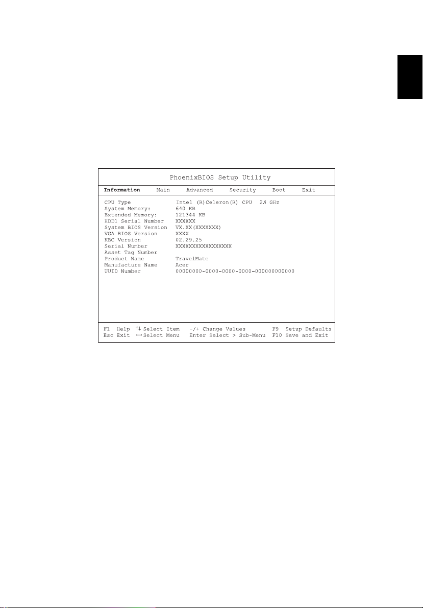
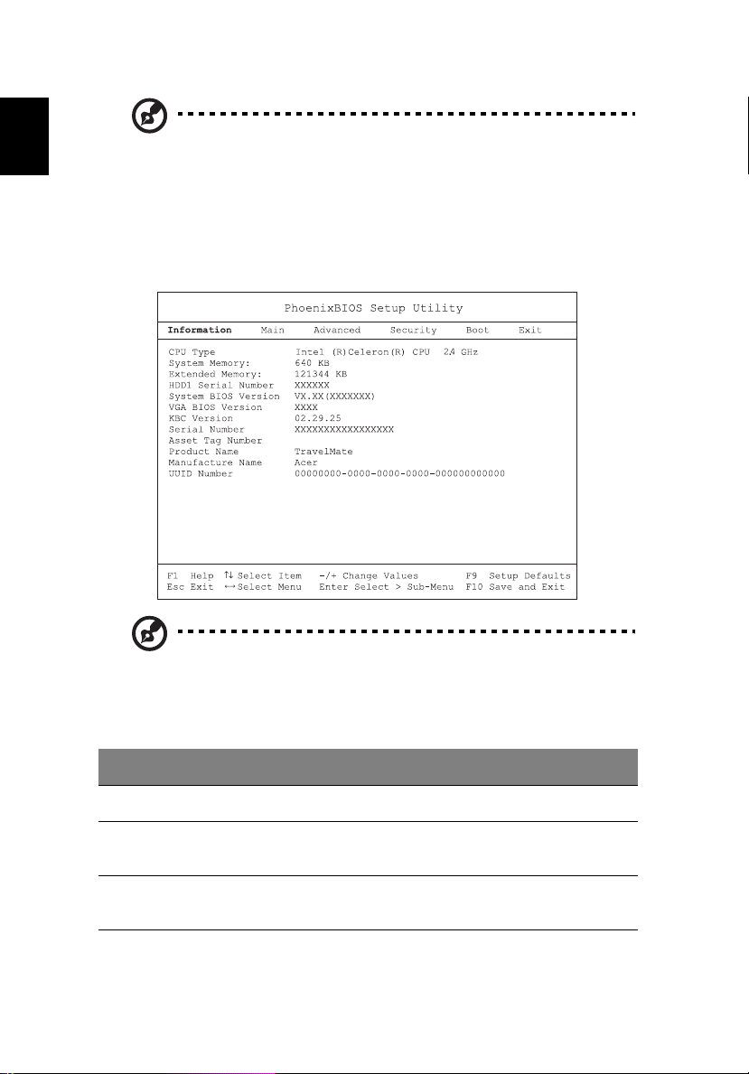
Information
The Information screen displays a summary of your computer hardware
information.
Note: The screen above is for reference only. Actual values may
differ.
The table below describes the parameters in this screen.
Parameter Description
CPU Type Describes the type of CPU installed in the system.
System Memory
(KB)
Extended
Memory (MB)
Shows the system memory size.
Shows the extended memory size.
Page 9
51
Parameter Description
HDD1 Serial
Number
System BIOS
Version
VGA BIOS
Version
KBC Version Shows the current keyboard controller (KBC) version
Serial Number Shows the system serial number.
Asset Tag
Number
Product Name Shows the official name of the product.
Manufacturer
Name
UUID Shows the universally unique identifier number.
Shows the primary master hard disk drive serial number.
Shows the system BIOS version.
Shows the video graphics accelerator BIOS version.
Shows the asset tag number.
Shows the name of the manufacturer.
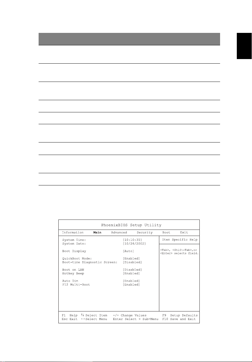
Main
The Main menu screen allows you to set basic settings about your
computer such as date and time and boot settings.
English
Page 10

2 Customizing my computer52
The table below describes the parameters in the screen.
English
Parameter Description
System
Time
System
Date
Boot
Display
QuickBoot
Mode
Boot-time
Diagnostic
Screen
Boot on
LAN
Hotkey
Beep
Auto Dim When enabled, the system will automatically dim the LCD
Sets the system time.
Format: HH:MM:SS (hour:minute:second)
Sets the system date.
Format: MMM DD YYYY (month day year )
Sets the display device when the computer starts up.
Options: Both or Auto
Quick Boot allows your computer to skip certain tests at startup to speed-up the boot process.
Options: Enabled or Disabled
Shows the logo during boot up.
Options: Enabled or Disabled
When enabled, allows your computer to boot up via the
network
Options: Enabled or Disabled
Enables or disables a beep when a hotkey is pressed.
Options: Enabled or Disabled
screen when system is running on battery power.
Options: Enabled or Disabled
F12 MultiBoot
When enabled, the “Fn-F12 for multi-boot” message will be
displayed during POST.
Options: Enabled or Disabled
Page 11
53
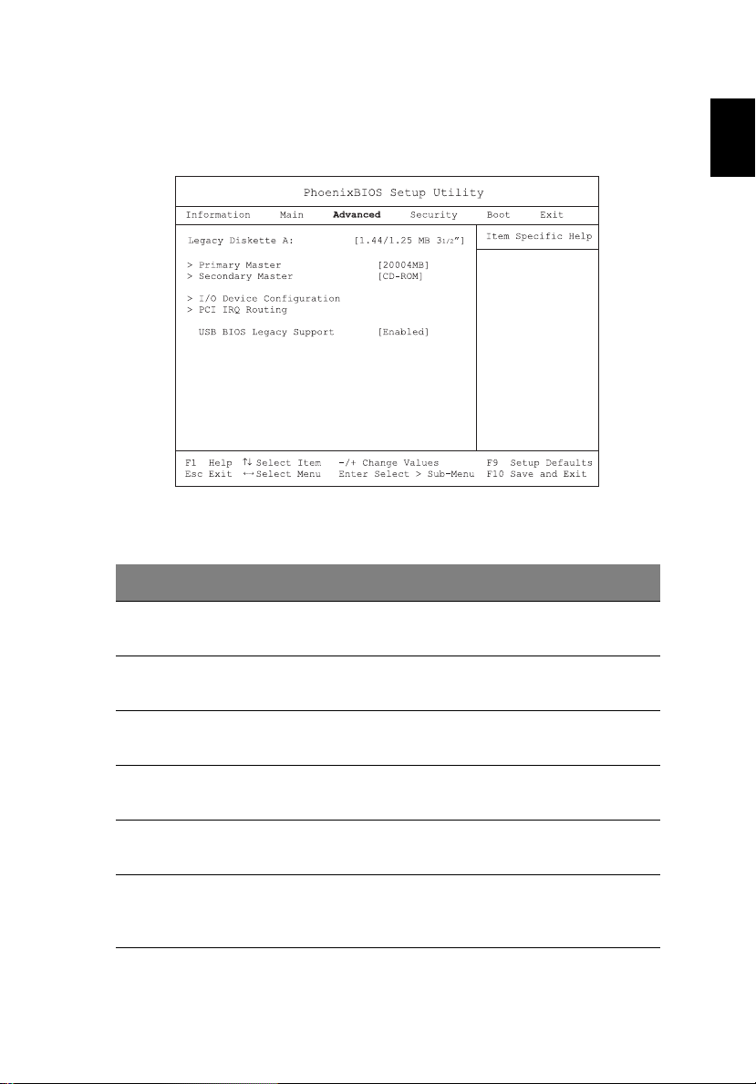
Advanced
The Advanced screen contains parameters values that define ho w your
computer behaves on startup.
The table below describes the parameters in this screen. Settings in
boldface are the default and suggested parameter settings.
Parameter Description
Legacy
Diskette A:
Shows the floppy drive information.
English
Primary
Master
Secondary
Master
I/O Device
Configuration
PCI IRQ
Routing
USB BIOS
Legacy
Support
Shows the hard disk information. Press Enter to access the
sub-menu.
Shows the optical drive information. Press Enter to access
the sub-menu.
Press Enter to access and set the I/O Device Configuration
sub-menu.
Press Enter to acces s and set th e PCI IR Q Rout ing s ub- menu.
Enables or disables t he USB BIOS Legacy Support.
Options: Enabled or Disabled
Page 12
2 Customizing my computer54
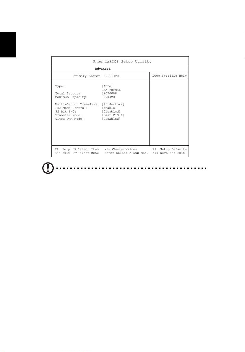
Primary Master
The Primary Master sub-menu contains parameters related to the hard
English
disk installed in your computer.
Caution: The parameters in this screen are for advanced uses only.
Typically, you do not need to change the values in this screen. The
default setting of Auto optimizes all the settings in your hard disk
drive.
Page 13
55
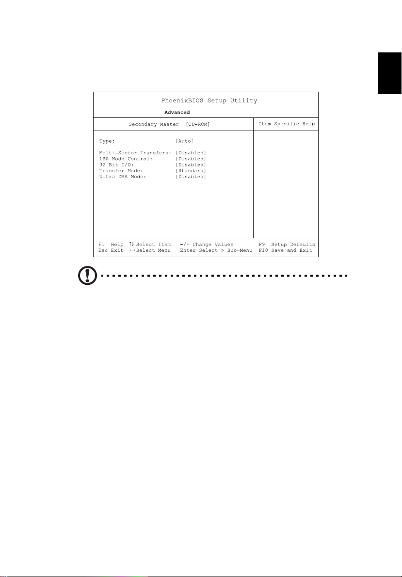
Secondary Master
The Secondary Master sub-menu contains parameters related to the
optical drive installed in your computer.
Caution: The parameters in this screen are for advanced uses only.
Typically, you do not need to change the values in this screen. The
default setting of Auto optimizes all the settings in your hard disk
drive.
English
Page 14
2 Customizing my computer56
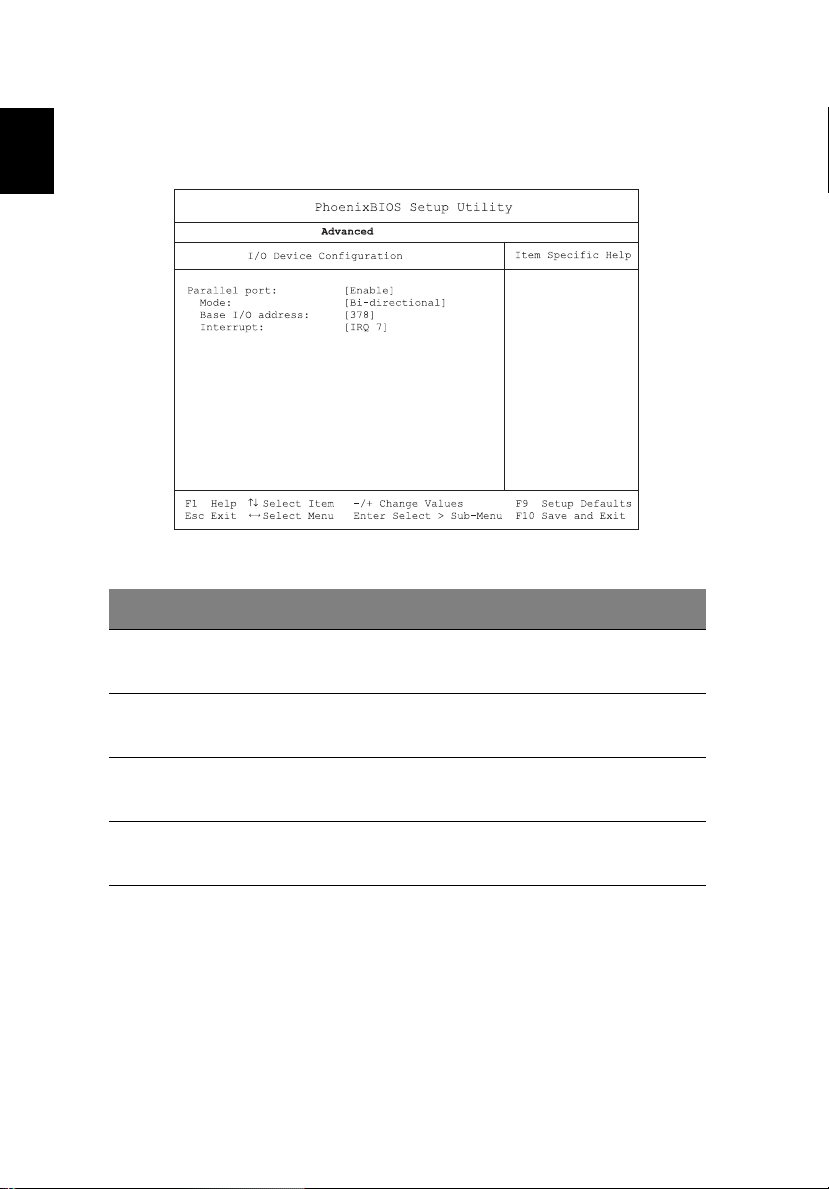
I/O Device Configuration
The I/O Device Configuration sub-menu contains parameters that are
English
related to your computer hardware.
Parameter Description
Parallel Port Enables or disables the parallel port.
Options: Enabled or Disabled
Mode Sets the operation mode of the parallel port.
Options: Output only, Bi-direction, EPP, or ECP
Base I/O Address Sets the I/O address of the parallel port.
Options: 3BC, 378h, or 278h
Interrupt Sets the interrupt request of the parallel port.
Options: IRQ 5 or IRQ 7
Page 15
57
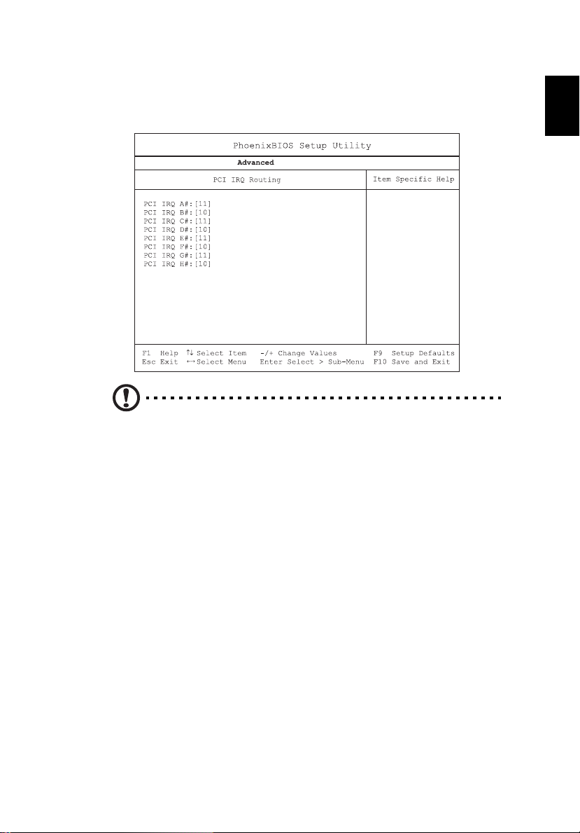
PCI IRQ Routing
The PCI IRQ Routing sub-menu allows you to set the IRQs for PCI
devices.
Caution: The parameters in this screen are for advanced users
only . T ypic ally, you do not need to change the values in this screen
because these values are already optimized.
English
Page 16

2 Customizing my computer58
Security
The Security screen contains parameters that help safeguard and
English
protect your comput er from unauthorized u se.
The table below describes the parameters in this screen. Settings in
boldface are the default and suggested parameter settings.
Parameter Description
Set Supervisor
Password
Set User Password When set, this password protects the computer from
Password on Boot When enabled, a pass word is requested when the
Set Primary Hard
Disk Password
When set, this password protects the BIOS Utility from
unauthorized entry.
Press Enter to set this password.
unauthorized entry during boot-up or resume from
Hibernation mode.
Press Enter to set this password.
system boots up.
Options: Enabled or Disabled
When set, this password prevents the primary hard
disk from unauthorized access. It consists of 8
alphanumeric characters.
Press Enter to set this password.
Page 17

59
Boot
The Boot menu contains parameter valu es that determine in what
order the bootable devices in your computer start-up.
Setting the Boot drive sequence
Use the cursor up/down keys to select a boot device, then press ↑ or ↓
to change its order. Items with a “+” sign can be further expanded.
English
Page 18

2 Customizing my computer60
Exit
This menu contains the exit options.
English
Parameter Description
Exit Saving
Changes
Exit Discarding
Changes
Load Setup
Defaults
Discard Changes Discards your changes.
Save Changes Saves your changes.
Saves your changes and exits the BIOS Utility.
Discards your changes and exits the BIOS Utility.
Loads default settings for all setup parameters.
Page 19

3 Troubleshooting
my computer
Page 20

This chapter instructs you on how to deal
with common system problems. Read it
before calling a technician if a problem
occurs. Solutions to more serious problems
require opening up the computer. Do not
attempt to open the computer by yourself.
Contact your dealer or an authorized
service center for assistance.
Page 21

63
Frequently-asked questions
The following is a list of possible situations that may arise during the
use of your computer. Easy answers and solutions are provided for
each one.
I pressed the power switch and opened the display, but the computer
does not start or boot-up.
Look at the Power indicator:
• If it is not lit, no power is being applied to the computer. Check
the following:
• If you are running on battery power, it may be low and unable
to power the computer. Connect the AC adapter to recharge
the battery pack.
• Make sure that the AC adapter is plugged in properly to the
computer and to the power outlet.
• If it is lit, check the following:
• If the Sleep indicator is lit, the computer is in Sleep mode.
Press any key or tap on the touchpad to resume.
• Is a non-bootable (non-system) diskette in the floppy drive?
Remove or replace it with a system diskette and press Ctrl-Alt-
Del to restart the system.
• The operating system files may be damaged or missing. Insert the
startup disk you created during Windows setup into the floppy
drive and press Ctrl-Alt-Del to restart the system. This will
diagnose your system and make necessary fixes.
English
Nothing appears on the screen.
The computer’s power management system automatically blanks the
screen to save power. Press any key to turn the display back on.
If pressing a key does not turn the display back on, two things might
be the cause:
• The brightness level might be too low. Press Fn-→ to increase the
brightness level.
• The display device might be set to an external monitor. Press the
display toggle hot key Fn-F5 to toggle the display back to the
computer.
Page 22

3 Troubleshooting my computer64
Image is not full-screen.
Make sure that the resolution is set to 1024x768. This is the native
English
resolution of your computer display. Right-click on your Windows
desktop and select Properties to bring up the Display Properties
dialog box. Then click on the Settings tab to make sure that the
resolution is set to the appropriate resolution. Resolutions lower than
the specified resolution are not full-screen on the computer or on an
external monitor.
No audio is heard from the computer.
Check the following:
• The volume may be muted. In Windows, look at the volume
control (speaker) icon on the taskbar. If it is crossed-out, click on
the icon and deselect the Mute option.
• The speakers may be turned off. Press Fn-F8 to turn the speakers
on (this hot key also turns the speakers off).
• The volume level may b e too low. In Windows, look at the volume
control icon on the taskbar.
• If headphones, earphones or external speakers are connected to
the line-out port, the internal speakers automatically turn off.
I want to eject the CD or DVD tray without turning on the power. I
cannot eject the CD or DVD tray.
There is a mechanical ej ect butt on on the CD-ROM or DVD-ROM driv e.
Simply insert the tip of a pen or paperclip and push to eject the tray.
Page 23

65
The floppy drive cannot access a diskette.
Check the following:
• Make sure the diskette is properly inserted in the floppy drive.
• Make sure the diskette is formatted.
• If the diskette is not the cause of the problem, the floppy drive
may be dirty. Clean it using a drive cleaning kit. Follow the
instructions included with the kit.
The CD or DVD drive cannot access a disc.
Check the following:
• Make sure the disc is supported by the drive. If your computer has
a CD-ROM drive, it can read CDs but cannot read DVDs. If your
computer has a DVD drive, it can read DVDs in addition to CDs.
• When placing the CD or DVD in the drive tray, make sure it is
secure in the spindle on the drive tray.
• Make sure the CD or DVD is free from scratches or smudges. If the
CD or DVD is dirty, clean it using a disc cleaning kit. Remember to
follow the instructions included with the kit.
• If the problem does not lie with the disc, your CD or DVD drive
may be dirty. Clean it using a drive cleaning kit. Follow the
instructions included with the kit.
English
The keyboard does not respond.
Try attaching an external keyboard to the USB connector on the
computer’s rear. If it works, contact your dealer or an authorized
service center as the internal keyboard cable may be loose.
The serial mouse does not work.
Check the following:
• Make sure that the serial cable is plugged securely into the serial
port.
• During the POST, press F2 to access the BIOS Utility and verify that
the serial port is enabled. See “BIOS Utility” on page 49 for more
details.
The printer does not work.
Check the following:
Page 24

3 Troubleshooting my computer66
• Make sure that the prin ter is connected to a pow er outlet and that
it is turned on.
English
• Depending on your connection (USB or parallel), make sure that
the printer cable is connected securely to the appropriate port on
your computer and the corresponding port on the printer.
• During POST, press F2 to access the BIOS Utility and verify that the
parallel port is enabled if you use a parallel printer.
I want to set up my location to use the internal modem.
To properly use your communications software, you need to set up
your location:
1 Click on Start, Control Panel.
2 Double-click on Phone and Modem Options.
3 Click on the Dialing Rules tab and begin setting up your loc atio n.
Refer to Windows Help and Support.
Page 25

67
Requesting service
International Travelers Warranty (ITW)
Your computer is backed by an International Traveler’s Warranty (ITW)
that gives you security and peace of mind when traveling. Our
worldwide network of service centers are there to give you a helping
hand.
An ITW passport comes with your computer. This passport contains all
you need to know about the ITW program. A list of available,
authorized service centers is in this handy booklet. Read this passport
thoroughly.
Always have your ITW passport on hand, especially when you travel to
receive the benefits from our support centers. Place your proof-ofpurchase in the flap located inside the front cover of the ITW passport.
If the country you are traveling in does not have an Acer-authorized
ITW service site, you can still get in contact with our offices worldwide.
Please consult www.acersupport.com
English
Before you call
Please have the follow ing inf ormat ion a vailabl e whe n you call Acer for
online service, and please be at your computer when you call. With
your support, we can reduce the amount of time a call takes and help
solve your problems efficiently .
If there are error messages or beeps reported by your computer, write
them down as they appear on the sc reen (or the num ber and sequenc e
in the case of beeps).
Page 26

3 Troubleshooting my computer68
You are required to provide the following information:
Name:________________________________________
English
Address:______________________________________
______________________________________________
Telephone number:____________________________
Machine and model type:_______________________
Serial number:_________________________________
Date of purchase:_____________________________ _
Page 27

Appendix A
SoftDial
Page 28

This appendix introduces the Acer Tablet PC
SoftDial, a unique new tool to increase the
ease of use of your Tablet PC.
Page 29

71
The Acer Tablet PC SoftDial?
Acer’s Tablet PC SoftDial is a radial device that manages program icons, system
settings/utilities, file folders and network locations. (INSERT IMAGE)
Surrounding the central Acer brand name logo are three levels of functionality
(level 1, level 2, and level 3) numbered from inner to outer.
You will notice, when the EMR stylus is moved near the SoftDial, that the Acer
brand name fades and is repl a ce d by a number of arrows. (INSERT TWO
IMAGES)
• The center arrow lets you drag the SoftDial wherever you
want it on the the screen. Simply press and hold the EMR
stylus to the (INSERT IMAGE) and drag it.
• The top arrow (12 o’clock position) vertically flips the display
output 180 degrees. This means what was at the top of the
screen, will now be at the bottom. Simply press the (INSERT
IMAGE).
• The left arrow (9 o’clock position) rotates the display output
90 degrees counter-clockwise. This changes the output from
landscape to portrait or vice versa. Simply press the (INSERT
IMAGE).
• The right arrow (3 o’clock position) rotates the display output
90 degrees clockwise. This changes the output from landscape
to portrait or vice versa. Simply press the (INSERT IMAGE).
English
Page 30

Appendix A SoftDial72
English
Page 31

Appendix B
Specifications
Page 32

This appendix lists the general specif ications
of your computer.
Page 33

75
Microprocessor
• Intel® Pentium® M processor with 1 MB L2 cache
Memory
• Main memory expandable to 2 GB
• Two DDR SDRAM DIMM slots
• Supports 256MB, 512MB, 1GB DDR SDRAM modules
• 512 KB Flash ROM BIOS; Shadow RAM support
Data storage
• One high-capacity, Enhanced-IDE hard disk
• One 5.25-inch internal CD-ROM, DVD-ROM, DVD/CD-RW combo,
DVD-RW, or DVD dual drive
Display and video
• 14.1" Thin-Film Transistor (TFT) liquid crystal-display (LCD)
supporting pen-based input, with 32-bit true-color at 1024x768
eXtended Graphics Array (XGA) resolution
or
• 14.1" Thin-Film Transistor (TFT) liquid crystal-display (LCD)
supporting pen-based input, with 32-bit true-color at 1400x1050
Super eXtended Graphics Array (SXGA) resolution
• Integrated VGA controller with Dynamic Vide o Memory Allocation
technology up to 64 M B
• Simultaneous LCD and external display support
• Dual view support
English
Audio
• 16-bit AC’97 stereo audio
• Dual stereo speakers
• Windows Sound System-compatible
• Separate audio ports for line-out, line-in devices
• Built-in internal microphone
Keyboard and pointing device
• 87/88/90-key Windows keyboard with 101/102 key emulation
Page 34

Appendix B Specificat ions76
• Ergonomically-centered touchpad pointing device with two
buttons and 4-way scroll button
English
I/O ports
• One Card bus type II card slot
• One smart-card slot
• One RJ-11 phone jack (V.90/V.92, 56Kbps modem)
• One RJ-45 network jack (Gigabit Ethernet)
• One DC-in jack (AC adapter)
• One external monitor (VGA) port
• One S-video TV out port
• One 100-pin port replicator connector
• One line-out (headphone) jack (3.5mm minijack)
• One line-in (microphone) jack (3.5mm minijack)
• Two USB 2.0 ports
• One 4-pin IEEE 1394 port
• One infrared (FIR) port
Weight and dimensions
• 2.83 kg (6.23 lbs) for 14.1" TFT model
• 326 (W) x 272 (D) x 33.4~35.9 (H) mm
Environment
• Temperature
• Operating: 5°C ~ 35°C
• Non-operating: -10°C ~ 60°C
• Humidity (non-condensing)
• Operating: 20% ~ 85% RH
• Non-operating: 20% ~ 85% RH
System
• Microsoft Windows XP Pro Tablet edition SP1
• ACPI compliant BIOS
• Phoenix BIOS
Page 35

77
• Suspend to RAM/Disk
Power
• Battery pack
• 8 cell Li-Ion battery pack
• 5.5 hours operating time with Battery mark 4.0
• AC adapter
•65-Watt
• Auto sensing 100~240V AC, 50~60Hz
Wireless Communications
• Optional Intel PRO/Wireless 2100 or 2100A module
• Optional MDC Bluetooth module (includes built-in antenna)
• Third party 802.11 a+g ready
Options
• 256MB/512MB/1GB memory upgrade module
• Additional AC adapter, Battery, or Weight-saver
• Hot-swapable optical drive
• 24x CD-ROM module
• 8x DVD module
• DVD/CD-RW combo module
•DVD+RW module
• Additional HDD module
English
Page 36

Appendix B Specificat ions78
English
Page 37

Appendix C
Notices
Page 38

This appendix lists the general notices of
your computer.
Page 39

81
FCC notice
This device has been tested and found to comply with the limits for a Class B
digital device pursuant to Part 15 of the FCC Rules. These limits are designed to
provide reasonable protection against harmful interference in a residential
installation. This device generates, uses, and can radiate radio frequency
energy and, if not installed and used in accordance with the instructions, may
cause harmful interference to radio communications.
However , there is no guarantee that interference will not occur in a particular
installation. If this device does cause harmful interference to radio or televisio n
reception, which can be determined by turning the device off and on, the user
is encouraged to try to correct the interference by one or more of the foll owing
measures:
• Reorient or relocate the receiving antenna
• Increase the separation between the device and receiver
• Connect the device into an outlet on a circuit different from that to which
the receiver is connected
• Consult the dealer or an experienced radio/television technician for help
Notice: Shielded cables
All connections to other computing devices must be made using shielded cables
to maintain compliance with FCC regulations.
Notice: Peripheral devices
Only peripherals (input/output devices, terminals, printers, etc.) certified to
comply with the Class B limits may be attached to this equipment. Operation
with non-certified peripherals is likely to result in interference to radio and TV
reception.
English
Caution
Changes or modifications not expressly approved by the manufacturer could
void the user’s authority, which is granted by the Federal Communications
Commission, to operate this computer.
Use conditions
This part complies with Part 15 of the FCC Rules. Operation is subject to the
following two conditions: (1) this device may not cause harmful interference,
and (2) this device must accept any interference received, including interference
that may cause undesired operation.
Page 40

Appendix C Notices82
Notice: Canadian users
This Class B digital apparatus meets all requirements of the Canadian
English
Interference-Ca us ing Equipment Regulatio ns .
Remarque à l’intention des utilisateurs canadiens
Cet appareil numérique de la classe B respected toutes les exigences du
Règlement sur le matériel brouilleur du Canada.
Modem notices
FCC
This equipment complies with Part 68 of the FCC rules. Located on the bottom
side of the modem is a label that contains, among other inform a t ion, the FCC
Registration Number and Ringer Equivalence Number (REN) for this equipment.
Upon request, you must provide this information to your telephone company.
If your telephone equipment causes harm to the telephone network, the
telephone company may discontinue your service temporarily. If possible, they
will notify you in adva nce. But, if advance notice is not pr a ctical, you will be
notified as soon as possible. You will also be informed of your right to file a
complaint with the FCC.
Your telephone company may make changes in its facilities, equipment,
operations, or procedures that could affect the proper functioning of your
equipment. If they do, you will be notified in advance to give you an
opportunity to maintain uninterrupted telephone service.
If this equipment should fail to operate properly, disconnect the equipment
from the phone line to determine if it is causing the problem. If the problem is
with the equipment, discontinue use and contact your dealer or vendor.
TBR 21
This equipment has been approved [Council Decision 98/482/EC - “TBR 21”] for
pan-European singl e ter m inal connection to the Public Switched Telephone
Network (PSTN). However, due to differences between the individual PSTNs
provided in different countries, the approval does not, of itself, give an
unconditional assurance of successful operation on every PSTN termination
point. In the event of problems, you should contact your equipment supplier in
the first instance.
Page 41

83
Important safety instructions
Read these instructions carefully. Save these instructions for future reference.
1 Follow all warnings and instructions marked on the product.
2 Unplug this product from the wall outlet before cleaning. Do not use
liquid cleaners or aerosol cleaners. Use a damp cloth for cleaning.
3 Do not use this product near water.
4 Do not place this pro duc t on an u nsta ble cart, st and, or ta ble . Th e produ ct
may fall, causing serious damage to the product.
5 Slots and openings in the cabinet and the back or bottom are provided for
ventilation; to ensure reliable operation of the product and to protect it
from overheating, these openings must not be blocked or covered. The
openings should never be blocked by placing the product on a bed, sofa,
rug, or other similar s ur f ace. This product should neve r be pla ced near or
over a radiator or heat reg is t e r, or in a built-in installation unless proper
ventilation is provided.
6 This product should be oper a t ed from the type of power indicated on the
marking label. If you are not sure of the type of power available, consult
your dealer or local power company.
7 Do not allow anything to rest on the power cord. Do not locate this
product where persons will walk on the cord.
8 If an extension cord is used with this product, make sure that the total
ampere rating of the equipment plu gge d into the extension cord does not
exceed the extension cord ampere rating. Also, make sure that the total
rating of all product s plugg ed int o the wall o utlet doe s not exceed the fu se
rating.
9 Never push objects of any kind into this product through cabinet slots as
they may touch dangerous voltage points or short out parts that could
result in a fire or electric shock. Never spill liquid of any kind on the
product.
10 Do not attempt to service this product yourself, as opening or removing
covers may expose you to dangerous voltage points or other risks. Refer all
servicing to qualified service personnel.
11 Unplug this product from the wall outlet and refer servicing to qualified
service personnel unde r t he f ollowing conditions:
a When the power cord or plug is damaged or frayed
b If liquid has been spilled into the product
c If the product has been exposed to rain or water
English
Page 42

Appendix C Notices84
d If the product does not operate normally when the operating
instructions are followed. Adjust only those controls that are covered
by the operating instructions since improper adjustment of other
English
controls may result in damage and will often require extensive work
by a qualified technician to restore the product to normal condition.
e If the product has been dropped or the cabinet has been damaged
f If the product exhibits a distinct change in performance, indicating a
need for service.
12 Replace the battery with the same type as the product's battery we
recommend. Use of another bat tery may present a risk of fi re or expl osion.
Refer battery replacement to a qualified serviceman.
13 Warning! Batteries may explode if not handled properly. Do not
disassemble or dispose of them in fire. Keep them away from children and
dispose of used batteries promptly.
14 Use only the proper type of p ower supply cord set (provid e d in your
accessories box) for this unit. It should be a detachable type: UL listed/C SA
certified, type SPT-2, rated 7A 125V minimum, VDE approved or its
equivalent. Maximum length is 15 feet (4.6 meters).
Laser compliance statement
The CD or DVD drive used with this comput er is a las er produc t. The CD or DVD
drive’s classification label (shown below) is located on the drive.
CLASS 1 LASER PRODUCT
CAUTION: VISIBLE AND INVISIBLE LASER RADIATION WHEN OPEN. AVOID
EXPOSURE TO BEAM.
APPAREIL A LASER DE CLASSE 1 PRODUIT
LASERATTENTION: RADIATION DU FAISCEAU LASER INVISIBLE EN CAS
D’OUVERTURE. EVITTER TOUTE EXPOSITION AUX RAYONS.
LUOKAN 1 LASERLAITE LASE R KL A SSE 1
VORSICHT: UNSICHTBARE LASERSTRAHLUNG, WENN ABDECKUNG GEÖFFNET
NICHT DEM STRAHLL AUSSETZEN
PRODUCTO LÁSER DE LA CLASE I
ADVERTENCIA: RADIACIÓN LÁSER INVISIBLE AL SER ABIERTO. EVITE
EXPONERSE A LOS RAYOS.
ADVARSEL: LASERSTRÅLING VEDÅBNING SE IKKE IND I STRÅLEN.
VARO! LAVATTAESSA OLET ALTTINA LASERSÅTEILYLLE.
VARNING: LASERSTRÅLNING NÅR DENNA DEL ÅR ÖPPNAD ÅLÅ TUIJOTA
SÅTEESEENSTIRRA EJ IN I STRÅLEN
Page 43

85
VARNING: LASERSTRÅLNING NAR DENNA DEL ÅR ÖPPNADSTIRRA EJ IN I
STRÅLEN
ADVARSEL: LASERSTRÅLING NAR DEKSEL ÅPNESSTIRR IKKE INN I STRÅLEN
Lithium battery statement
The TravelMate 240P/250P series uses the lithium battery, models BTP58A1, BTP-59A1 and BTP-60A1 only.
CAUTION
Danger of explosion if battery is incorrectly replaced. Replace only with the
same or equivalent type recommended by the manufacturer. Discard used
batteries according to the manufacturer’s instructions.
ADVARSEL!
Lithiumbatteri - Eksplosionsfare ved fejlagtig håndtering. Udskiftning må kun
ske med batteri af samme fabrikat og type. Léver det brugte batteri tilbage til
leverandøren.
ADVARSEL
Eksplosjonsfare ved feilaktig skifte av batteri. Benytt samme batteritype eller
en tilsvarende type anbefalt av apparatfabrikanten. Brukte batterier kasseres i
henhold til fabrikantens instruksjoner.
VARNING
Explosionsfara vid felaktigt batteribyte. Anvãnd samma batterityp eller en
ekvivalent typ som rekommenderas av apparattillverkaren. Kassera anvãnt
batteri enligt fabrikantens instruktion.
VAROITUS
Päristo voi räjähtää, jos se on virheellisesti asennettu. Vaihda paristo
ainoastaan laitevalmistajan suosittelemaan tyyppiin. Hävitä käytetty paristo
valmistajan ohjeiden mukaisesti.
VORSICHT!
Explosionsgefahr bei unsachgemäßen Austausch der Batterie Ersatz nur durch
denselben oder einem vom Hersteller empfohlenem ähnlichen Typ. Entsorgung
gebrauchter Batterien nach Angaben des Herstellers.
English
LCD pixel statement
The LCD unit is produced with high-precision manufacturing techniques.
Nevertheless, some pixels may occasionally misfire or appear as black or colored
dots. This has no effect on the recorded image and does not constitute a
malfunction.
Page 44

Appendix C Notices86
Macrovision copyright protection notice
English
This product incorp or a t e s copyright protection technology that is protected by
method claims of certain U.S. patents and other intellectual property rights
owned by Macrovision Corporation and other rights owners. Use of this
copyright protect ion technology must be authori zed by Macrovision
Corporation, and is int ended for home and other limi t e d viewing uses only
unless otherwise authorized by Macrovision Cor por ation. Reverse enginee ring
or disassembly is prohibited.
Apparatus Claims of U.S. Patent Nos. 4,631,603, 4,577,216, 4,819,098, and
4,907,093 licensed for limited viewing uses only.
A-Tick notice
For safety reasons, only connect headsets with a telecommunications
compliance label. This includes customer equipment previously labelled
permitted or certified. The unit shall be connected to Telecommunication
Network through a line cord which meets the requirements of ACA Technical
Standard TS008. Australian approved mains cord set shall be used with the
equipment.
Note: Below regulatory information is for models with wireless
LAN and/or Bluetooth only.
Regulatory Information
The Wireless module must be installed and used in strict accordance with the
manufacturer’s instructions. This device complies with the following radio
frequency and safety standards.
Canada - Industry Canada (IC)
• This device complies with RSS 210 of Industry Canada.
Europe - EU Declaration of Conformity
This device complies with the standards listed below, following the provisions
of the EMC Directive 89/336/EEC:
• ETSI EN 301 489-1/17
• ETSI EN 300 328-2
• EN 300 328 V1.4.1.
Page 45

87
USA - Federal Communications Commission (FCC)
This device complies with Part 15 of FCC Rules. Operation of the devices in an
Wireless LAN System is subject to the following two conditions:
• This device may not cause harmful interference.
• This device must accept any interference that may cause undesired
operation.
Exposure to Radio Frequency Radiation
The radiated output power of the Wireless module is far below the FCC radio
frequency exposure limits. Nevertheless, the Wireless module shall be used in
such a manner that the potential for human contact during normal operation is
minimized.
The transmitter and the antenna are permanently installed inside the
notebook, and are specific for this model (not for generic computer). The
antenna of this device is installed on the top of the LCD display.
This transmitter must not be co-located or operating in conjunction with any
other antenna or transmitter.
-This equipment has been tested and found to comply with the limits for a Class
B digital device, pursuant to Part 15 of the FCC Rules. These limits are designed
to provide reasonable protection against harmful interference in a residential
installation. This equipment generates, uses a nd ca n r a diate radio frequency
energy and, if not installed and used in accordance with the instructions, may
cause harmful interference to radio communications. However, there is no
guarantee that interference will not occur in a particular installation. If this
equipment does cause harmful interference to radio or television reception,
which can be determined by t ur ning the equipment off and on, the user is
encouraged to try to correct the interference by one of the following measures:
• Reorient or relocate the receiving antenna.
• Increase the separation between the equipment and receiver.
• Connect the equipment into an outlet on a circuit different from that to
which the receiver is connected.
• Consult the dealer or an experienced radio/TV technician for help.
English
FCC Caution: To ass ure con tinu ed c ompli anc e, an y chan ges or modi fic ation s no t
expressly approved by the party responsible for compliance could void the
user's authority to operate this equipment (exa mple - us e only shielded
interface cables when connecting to computer or peripheral devices).
Page 46

Appendix C Notices88
This device complies with Part 15 of the FCC Rules. Operation is subject to the
following two conditions: (1) This device may not cause harmful interference,
and (2) this device must accept any interference received, including interference
English
that may cause undesired operation.
Page 47

89
Index
A
AC adapter
caring for v
audio 28
troubleshooting 64
B
battery pack
caring for v
charging indicator 15
BIOS Utility 49– 60
Advanced menu
i/o device configurat ion 56
pci irq routing 57
primary master 54
secondary master 55
advanced menu 53
boot menu 59
exit menu 60
main menu 51
navigating 49
security menu 58
BIOS utility 49
brightness
hotkeys 21
C
caps lock 17
on indicator 15
care
AC adapter v
battery pack v
computer iv
CD
troubleshooting 65
CD-ROM
ejecting 26
ejecting manually 64
troubleshooting 64
cleaning
computer v
computer
bringing to meetings 32
caring for iv
cleaning v
disconnecting 31
features 3, 12
indicators 14
keyboards 17
moving around 31
on indicator 14
performance 12
security 36
setting up a home office 33
taking home 32
traveling internationally 34
traveling on local trips 34
troubleshooting 62
turning off iv
CPU 50
D
date
setting in BIOS Utility 52
display
hotkeys 21
troubleshooting 63, 64
DVD 27
troubleshooting 65
DVD movies
playing 27
DVD RW drive 12
E
Ethernet 42
Euro 21, 22
F
FAQ. See frequently-asked questions
floppy drive
troubleshooting 65
frequently-asked questions 63
front view 3
H
hard disk 26
help
online services 67
Hibernation mode
hotkey 20
hotkeys 20
English
Page 48

90
I
indicator lights 14
ITW. See warranty
English
K
keyboard 17
embedded numeric keypad 18
hotkeys 20
lock keys 17
troubleshooting 65
Windows keys 19
L
LEDs 14
M
media access
on indicator 14
memory
installing 45 – 46
upgrading 44
modem 41
mouse
troubleshooting 65
N
network 42
Notebook Manager 47
hotkey 20
notice
DVD copyright protection 86
num lock 17
on indicator 15
numeric keypad
embedded 18
num lock 18
O
online services 67
optical drive 26
options
memory upgrade 44
P
parallel por t
setting in BIOS Utility 56
PC Card 43
ejecting 43
inserting 43
ports 41
POST (power-on self-test) 49
printer
troubleshooting 65
problems 63
CD 65
CD-ROM 64
diskette 65
display 63, 64
DVD 65
floppy drive 65
keyboard 65
printer 65
serial mouse 65
startup 63
troubleshooting 62
Q
questions
setting location for modem use
66
S
safety
CD-ROM 84
FCC notice 81
general instructions 83
modem notices 82
scroll lock 17
security
keylock 36
service
when to call vi
speakers
hotkey 21
troubleshooting 64
specifications 70, 74
Standby mode
hotkey 20
status indicator 14
status indicators 14
storage 26
CD, DVD, or DVD/CD-RW combo
drive 26
hard disk 26
support
information 67
Page 49

91
T
time
setting in BIOS Utility 52
touchpad 24
hotkey 21
using 24– 25
travel
international flights 34
local trips 34
troubleshooting 62
U
universal serial bus 42
Using computer in tablet mode 9
utility
BIOS Setup 49– 60
V
view
front 4
left 4
rear 6
right 5
W
warranty
International Traveler’s Warran-
ty 67
Windows keys 19
English
Page 50

92
English
 Loading...