


SRB-160S
NETWORK STORAGE
User Manual

Copyright
©2017
Hanwha Techwin
Co., Ltd. All rights rese rved.
Trademark
Each of trademarks herein is registered. The name of this product and other trademarks mentioned in this manual are the registered
trademark of their respective company.
Restriction
Copyright of this document is reserved. Under no circumstances, this document shall be reproduced, distributed or changed, partially or
wholly, without formal authorization.
Disclaimer
Hanwha Techwin
makes the best to verify the integrity and correctness of the contents in this document, but no formal guarantee
shall be provided. Use of this document and the subsequent results shall be entirely on the user’s own responsibility.
Hanwha Techwin
reserves the right to change the contents of this document without prior notice.
Design and specifications are subject to change without prior notice.
NETWORK STORAGE
User Manual

English - 3
● OVERVIEW
IMPORTANT SAFETY INSTRUCTIONS
Read these operating instructions carefully before using the unit. Follow all the safety instructions
listed below. Keep these operating instructions handy for future reference.
1) Read these instructions.
2) Keep these instructions.
3) Heed all warnings.
4) Follow all instructions.
5) Do not use this apparatus near water.
6) Clean the contaminated area on the product surface with a soft, dry cloth or a damp cloth.
(Do not use a detergent or cosmetic products that contain alcohol, solvents or surfactants
or oil constituents as they may deform or cause damage to the product.)
7) Do not block any ventilation openings, Install in accordance with the manufacturer’s
instructions.
8) Do not install near any heat sources such as radiators, heat registers, stoves, or other
apparatus (including amplifiers) that produce heat.
9) Do not defeat the safety purpose of the polarized or grounding- type plug. A polarized plug
has two blades with one wider than the other. A grounding type plug has two blades and a
third grounding prong. The wide blade or the third prong are provided for your safety. if the
provided plug does not fit into your outlet, consult an electrician for replacement of the
obsolete outlet.
10) Protect the power cord from being walked on or pinched particularly at plugs, convenience
receptacles, and the point where they exit from the apparatus.
11) Only use attachments/accessories specified by the manufacturer.
12) Use only with the cart, stand, tripod, bracket, or table specified by
the manufacturer, or sold with the apparatus. When a cart is used,
use caution when moving the cart/apparatus combination to avoid
injury from tip-over.
13) Unplug this apparatus during lightning storms or when unused for
long periods of time.
14) Refer all servicing to qualified service personnel. Servicing is required when the apparatus
has been damaged in any way, such as power-supply cord or plug is damaged, liquid has
been spilled or objects have fallen into the apparatus, the apparatus has been exposed to
rain or moisture, does not operate normally, or has been dropped.
Battery
Batteries(battery pack or batteries installed) shall not be exposed to excessive heat such as
sunshine, fire or the like.
Caution
Risk of Explosion if Battery is replaced by an Incorrect Type. Dispose of Used Batteries According
to the Instructions.
overview

overview
4_
overview
BEFORE START
This manual provides operational information necessary for using the product and contains a
description about each component part and its function as well as menu or network settings.
You have to keep in mind the following notices :
• Hanwha Techwin retains the copyright on this manual.
• This manual cannot be copied without Hanwha Techwin’s prior written approval.
• We are not liable for any or all losses to the product incurred by your use of non-standard
product or violation of instructions mentioned in this manual.
• Prior to opening the case, please consult a qualified technician first. Whenever this is needed
power must be removed from the unit.
• Before installing additional HDD to this product, check if it is compatible with the product.

English - 5
● OVERVIEW
CONTENTS
OVERVIEW
3
3 Important Safety Instructions
4 Before Start
5 Contents
7 Features
9 Part Names and Functions (Front)
11 Part Names and Functions (Rear)
INSTALLATION
12
12 Installing HDD
14 Turn on the System
15 Connecting the iSCSI
16 Starting the system
18 Setting the administrator’s Initial password
WEB VIEWER PROGRAM
19
19 Recommended System Specifications
19 Major Features
20 Execute
20 Access
20 Shutdown/Reboot
21 Storage
25 Network
28 System
REMOTE MANAGER UTILITY
31
31 System Requirements
31 Main Features
32 REMOTE MANAGER Installation
34 Composition and Menu of the REMOTE
MANAGER
35 Network Settings
36 Storage Settings
37 Disks Information
38 Update Firmware

overview
6_
overview
USING THE DEVICE AS AN ISCSI
STORAGE
41
41 Using an iSCSI storage on Windows OS
43 Using an iSCSI storage on LINUX
TROUBLE SHOOTING
45
45 RAID Level and Status Message on LCD
46 ONE-TOUCH button setup error
47 Internet Explorer authentication failure
48 Windows iSCSI initiator connection failure
48 Firmware update failure in Safari browser on
Mac
SPECIFICATION
49
49 Specification
ONE-TOUCH BUTTON SETUP
39
39 What is the ONE-TOUCH BUTTON SETUP?
40 Starting the ONE-TOUCH BUTTON SETUP

English - 7
● OVERVIEW
FEATURES
•
Large capacity network storage
•
Compatible NVR : SSM-RS, PRN-4011, XRN-1610/1610S, XRN-2010/2011
•
Throughput
Classification Performance
Enterprise HDD
Group 1 400Mbps
800Mbps
Group 2 400Mbps
Surveillance HDD
Group 1 300Mbps
600Mbps
Group 2 300Mbps
※ Use only enterprise HDDs for SSM-RS.
•
16 Hot-swappable HDD (Max. 128TB with 8TB HDDs)
•
RAID Mode : 0/10/5/6, RAID5+Hotstandby
•
ONE-TOUCH settings : Create a RAID volume and an iSCSI target by pushing the one-touch button.
•
Up to 8 virtual storage volumes can be set, and NVR can be allocated for each volume.
(A single storage can be shareable by up to eight NVRs.)
•
Network Bonding: Network fail-over, load balancing and link-aggregation
•
Remote management with a web viewer and a client application.
•
4 Giga-bit network ports
•
3U Rackmount, Front cover with a key lock
•
Redundant power supply

overview
8_
overview
Package Contents
Please unwrap the product, and place the product on a flat place or in the place to be installed.
Please check the following contents are included in addition to the main unit.
M
`
The appearance of the components may differ from the image shown.
`
Accessory category and quantity may differ depending on sales region.
Main Frame Network Cable Power Cable
Rack Mount Kit
HDD door lock key /
HDD Screws (1 bag) /
Rack Mount Screws (1 bag)
User Manual /
Remote Manager software
English - 9
● OVERVIEW
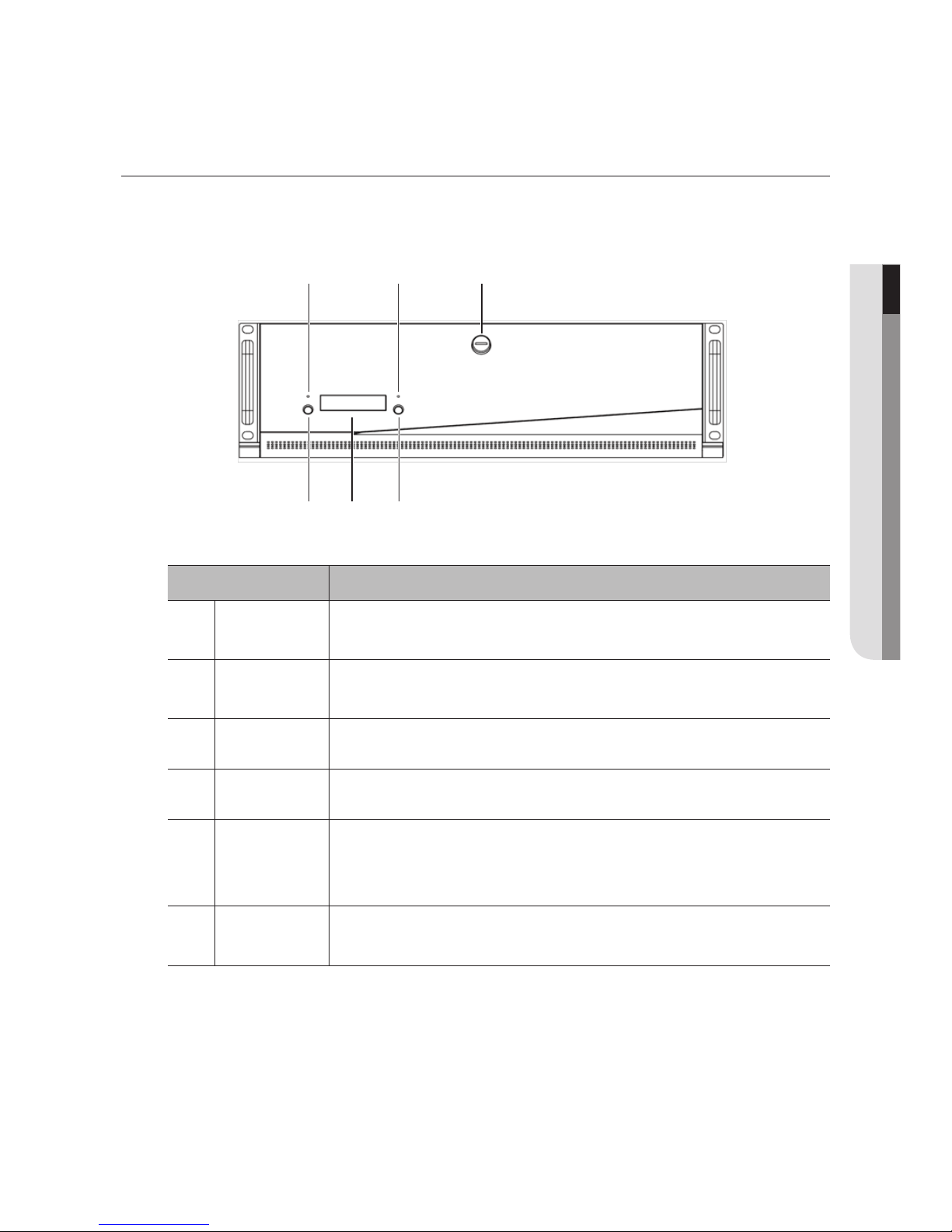
Part Names Functions
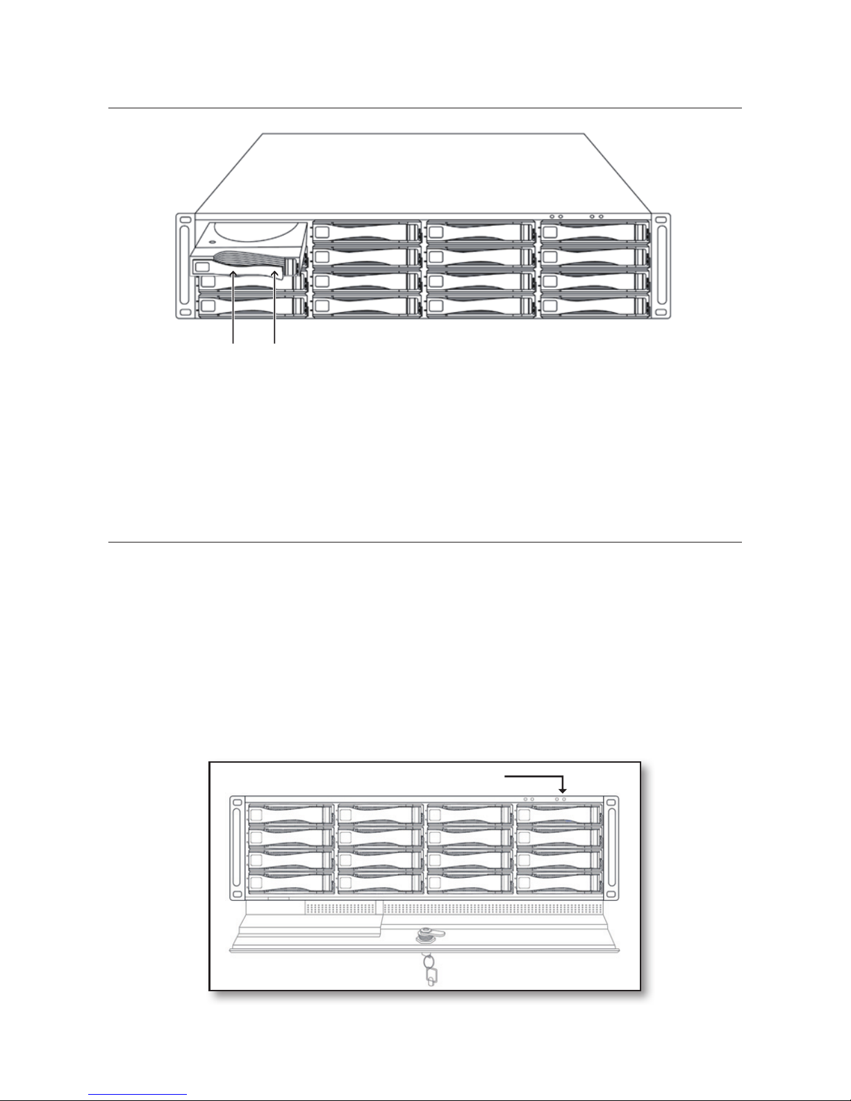
a
ERROR LED
(Red)
Lights on when an error occurs.
b
Network LED
(White)
Lights on when RAID rebuilding is in progress or the data is transferring.
c
Door-Lock Key
Locks or unlocks the door of the front panel with using the enclosed door-lock key.
d
Front LCD Displays the status of the device.
e
Button 1
It’s used when the ONE-TOUCH Button is performed and when the power off is
performed.
(Please refer to the ONE-TOUCH BUTTON SETUP section. (pages 39~40)
f
Button 2
It’s used when the status displayed on the front LCD is changed and when
the ONE-TOUCH Button setup and the power off are canceled.
PART NAMES AND FUNCTIONS (FRONT)
Front I
a
e fd
b c
overview
10_
overview
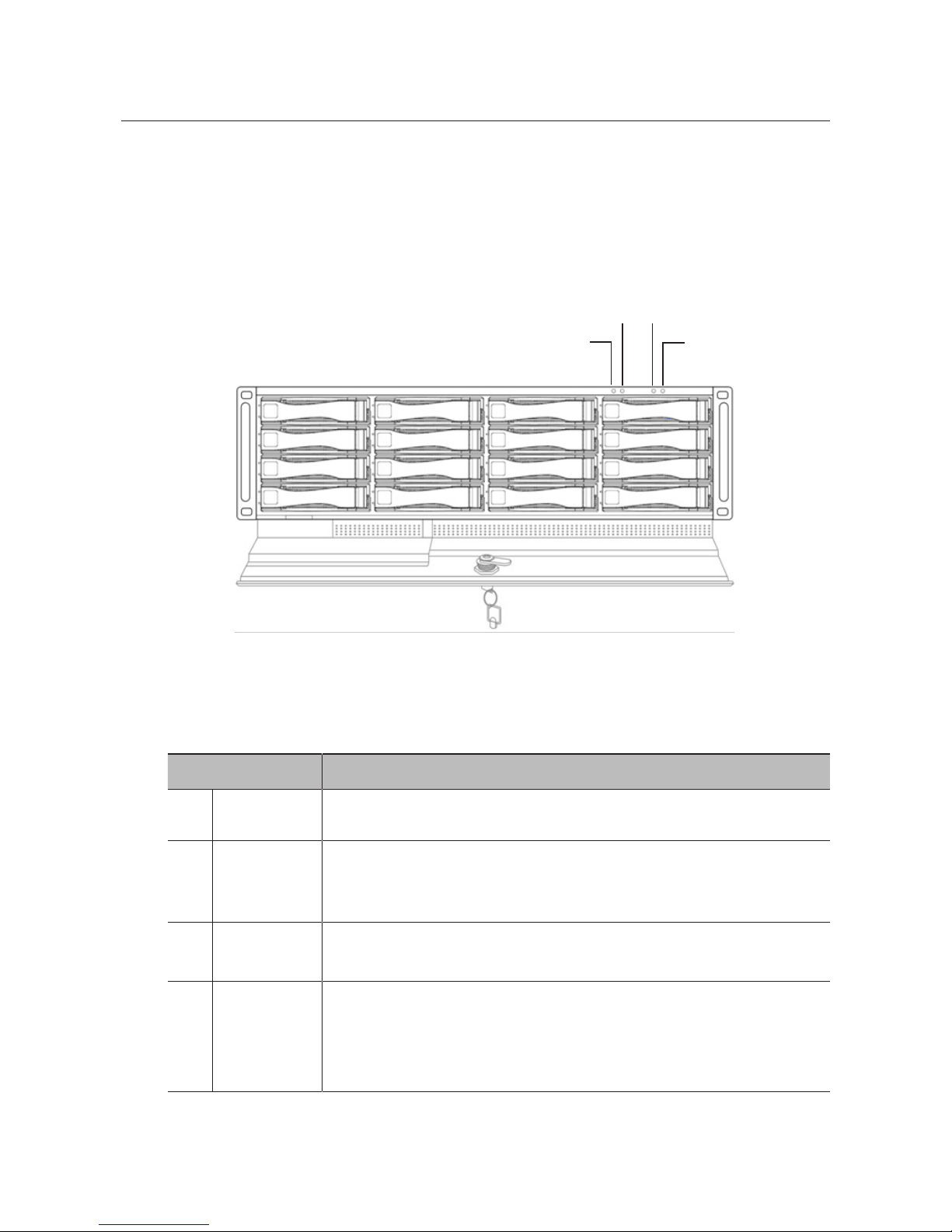
Part Names Functions
a
Mute LED (Red)
Lights on when the mute function is operated.
b
Mute Switch
This switch can be used to mute the beep that is sounded when a problem occurs from
the device. Press and hold it for 1 or 2 seconds, and then a red LED will turn on to notify
you that the device is muted.
c
Power LED
(Blue)
Lights on when the system turns on.
d
Power Switch
Turns on or off the system.
`
Press the power switch at least 2 seconds to turn on the system.
`
To turn off the system, press the power switch at least 2 seconds and press the Button
1 located at Front I. (Please refer to the Part Names and Functions (Front I). page 9)
Front II
a
b
c
d
English - 11
● OVERVIEW
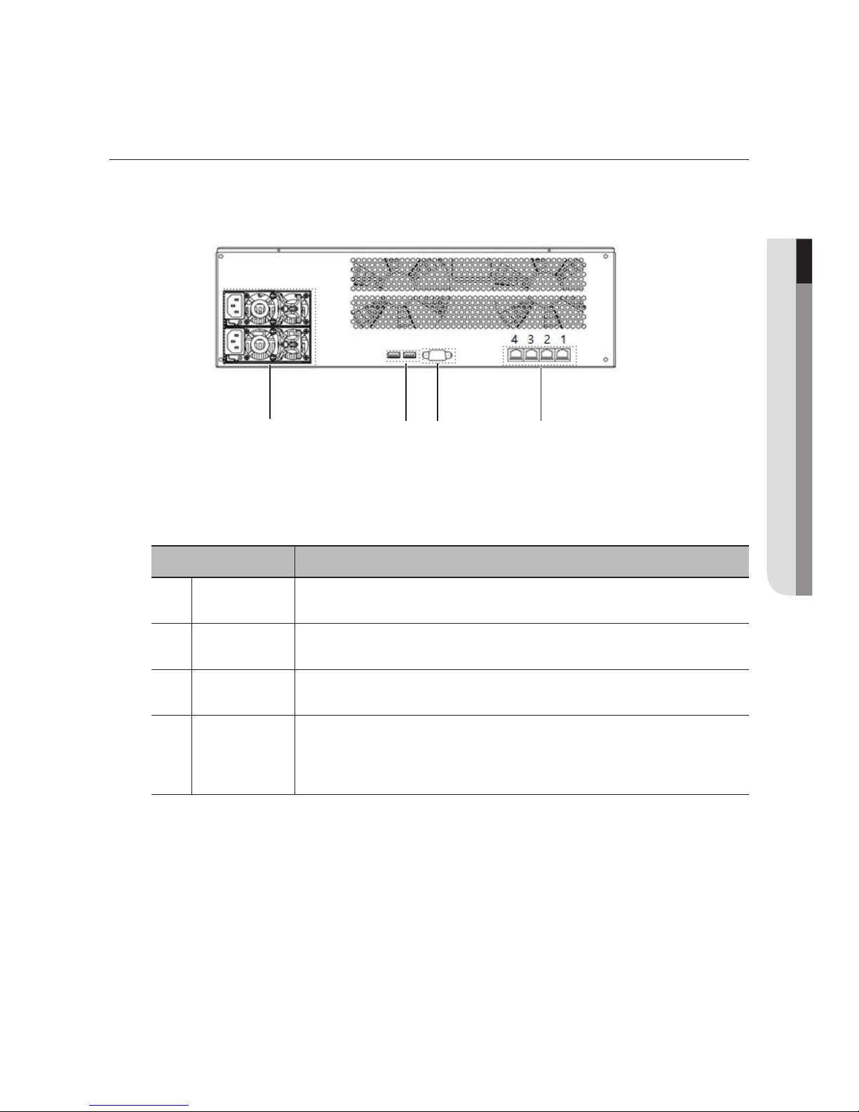
Part Names Functions
a
Power Supply
Outputs Max. 300W (Redundant)
b
USB port Connects the USB devices.
c
Console port
Used for the system setting in the factory.
d
Network port
Port 1: Connects the device with a network switch for data transferring.
Port 2,3,4: Connects the device with a network switch together the Port 1 for Network
Bonding.
PART NAMES AND FUNCTIONS (REAR)
a
b c d

12_
installation
installation
Please take note of the followings before using this product.
•
Do not use the product outdoor.
•
Do not spill water or liquid in the connection part of the product.
•
Do not impose the system to excessive shock or force.
•
Do not pull out the power plug forcefully.
•
Do not disassemble the product on your own.
•
Do not exceed the rated input/output range.
•
Use a certified power cord only.
•
For the product with an input ground, use a grounded power plug.
•
Mount at least 1 internal HDD in the NVR to connect, and then connect this product.
•
It is recommended to install a rack to ensure stable operation. At this time, the rack must be installed on the
shelf or be fixed with a rack mounting kit.
INSTALLING HDD
Make sure to unplug the power cord from the wall outlet to prevent possible electric shock, injury or product
damage.
Please consult your provider for further information on HDD installation since improper installation or
settings may damage the product.
`
Make sure to unplug the power cord from the wall outlet before proceeding with the installation.
J
`
Cautions for data loss (HDD care)
Please pay attention so that the data inside the HDD is not damaged.
Before adding a HDD, please check the compatibility with this product.
HDD is vulnerable to malfunction due to its sensitive nature especially against shock when
operating.
Please ensure that the HDD is free from such shock.
We are not liable for any damage to the HDD incurred by user’s carelessness or miss use.
`
Cases might cause damage to HDD or recorded data
To minimize the risk of data loss from a damaged HDD, please backup data as often as possible.
If exposed to shock when disassembling or installing, data stored in the hard disk may be
damaged.
A sudden power failure or turning off the product while in HDD operation may damage the
hard disk drive.
HDD or files stored inside may be damaged if the main body is moved or impacted during the
HDD operation.
English - 13
● INSTALLATION
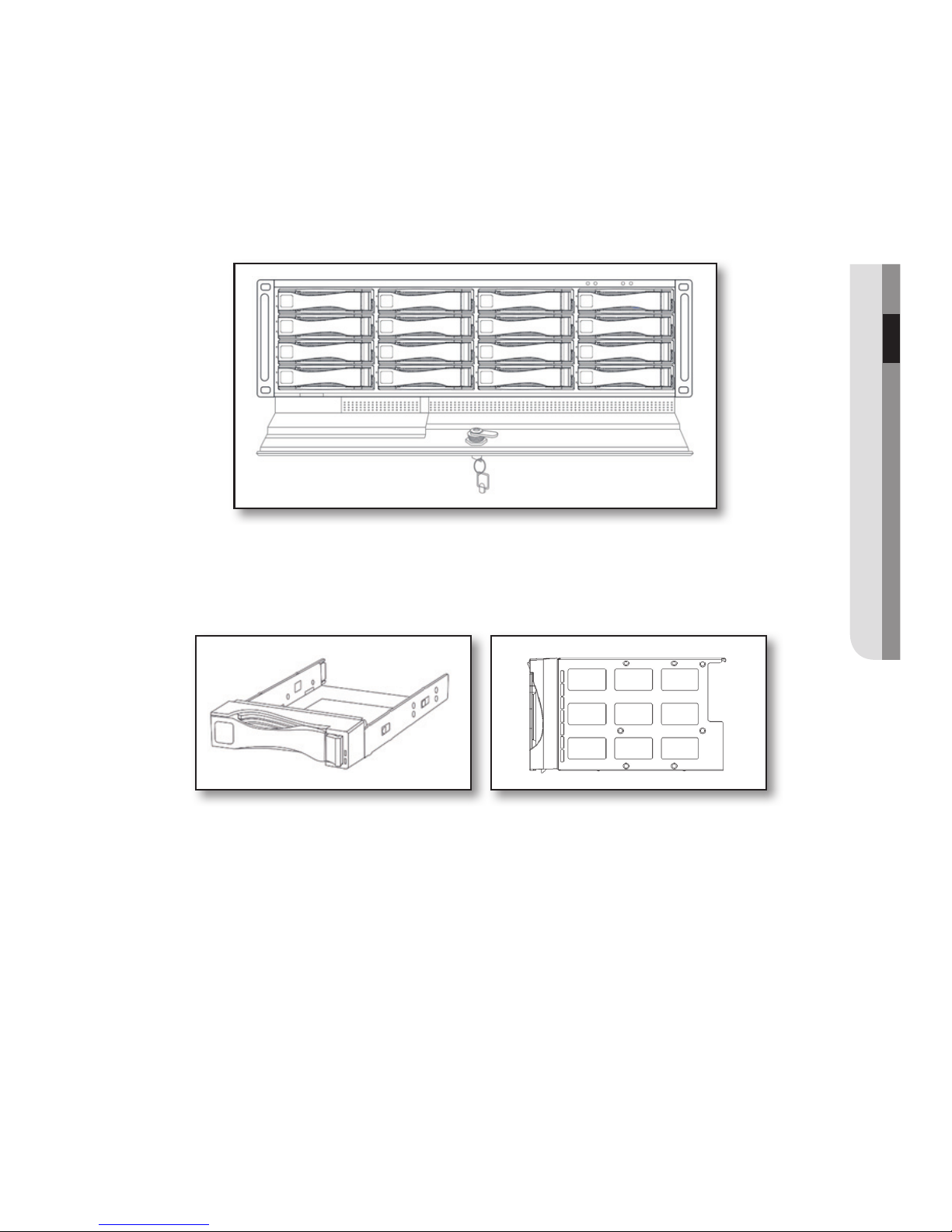
Install the SATA HDD (maximum 16) following the instruction.
1. Open the door of the front.
2. Open the door of the front panel by using the enclosed door-lock key.
3. Remove the 16 hot-swap drive bays by pulling the handles toward you.
4. Secure 16 SATA HDD to the hot-swap drive bays using the enclosed screws.
5. Insert the hot-swap drive bay into the back of the main frame.
6. Gently push the drive bay until it reaches the end of the main frame, and then secure it to the
frame using the handle.
7. Repeat the procedure to insert SATA HDD to the other 15 hot-swap drive bays.
installation
14_
installation
ox
J
`
The HDDs to be installed should be the same model and capacity.
`
When you insert a hot-swap drive bay, push the end of the drive handle.
Turn on The SySTem
1. Connect the power cable of the device to the wall outlet.
2. Connect the network cable to the Network Port 1 on the rear panel of the device and the network
port of the gigabit switch.
3. Press the power switch on the front panel for at least 2 seconds.
4. If the device is turned on, it activates a beeping sound and the system booting will be started.
Power Switch
English - 15
● INSTALLATION
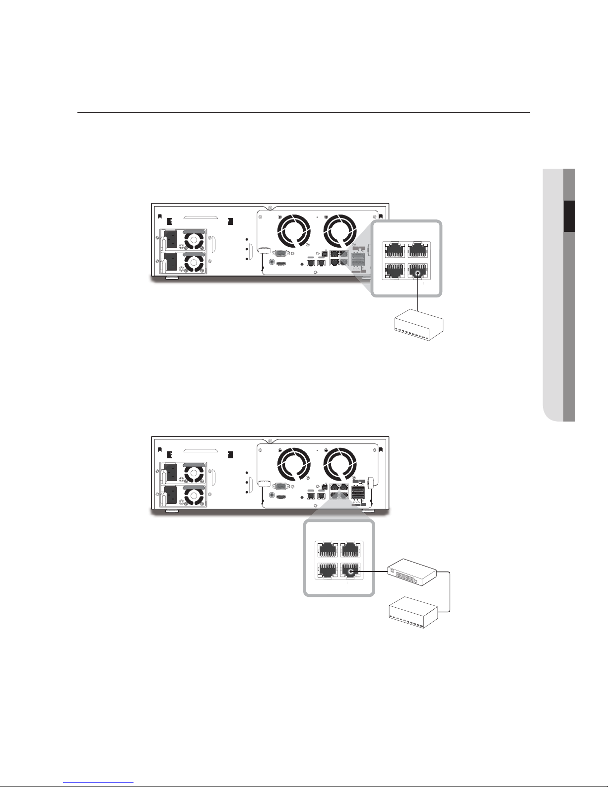
CONNECTING THE iSCSI
VGA
L.FAN R.FAN
HDMI
AUDIO OUT
CONSOLE
NETWORK 1
NETWORK 1 NETWORK 3
NETWORK 2 iSCSI
NETWORK 2
OPTICAL OPTICAL
Tx
RS-232
RxG
1
NO
COMCOM COM
NO NO
1
2 3 4
ALARM
RESET
432
NO
COM
NC
G
G
ALARM
OUT
ALARM
IN
ALARM OUT
NETWORK
2
iSCS
I
ALARM
NETWORK 1 NETWORK 3
NETWORK 2 iSCSI
NETWORK
2
iS
NETW
O
RK
3RK1
NETW
PPPoE
모뎀
스위치
네트워크
카메라
Phone
(PPPoE)
Line
네트워크
스위치
Windows
네트워크 뷰어
VGA
L.FAN R.FAN
HDMI
AUDIO OUT
CONSOLE
NETWORK 1
NETWORK 1 NETWORK 3
NETWORK 2 iSCSI
NETWORK 2
OPTICAL OPTICAL
Tx
RS-232
RxG
1
NO
COMCOM COM
NO NO
1
2 3 4
ALARM
RESET
432
NO
COM
NC
G
G
ALARM
OUT
ALARM
IN
ALARM OUT
K 3
N
O
COMCOMCO
M
NON
O
1
3
ALARM
RESE
T
432
NO
COM
NC
G
G
ALARM
OUT
ALARM
IN
ALARM OUT
NETWORK 1 NETWORK 3
NETWORK 2 iSCSI
ORK 2 iSCSI
VGA
L.FAN R.FAN
HDMI
AUDIO OUT
CONSOLE
NETWORK 1
NETWORK 1 NETWORK 3
NETWORK 2 iSCSI
NETWORK 2
OPTICAL OPTICAL
Tx
RS-232
RxG
1
NO
COMCOM COM
NO NO
1
2 3 4
ALARM
RESET
432
NO
COM
NC
G
G
ALARM
OUT
ALARM
IN
ALARM OUT
NETWORK
2
iSCS
I
2
ALARM
NETWORK 1 NETWORK 3
NETWORK 2 iSCSI
NETWORK
2
iS
NETW
O
RK
3RK1
NETW
PPPoE
모뎀
스위치
네트워크
카메라
Phone
(PPPoE)
Line
네트워크
스위치
Windows
네트워크 뷰어
VGA
L.FAN R.FAN
HDMI
AUDIO OUT
CONSOLE
NETWORK 1
NETWORK 1 NETWORK 3
NETWORK 2 iSCSI
NETWORK 2
OPTICAL OPTICAL
Tx
RS-232
RxG
1
NO
COMCOM COM
NO NO
1
2 3 4
ALARM
RESET
432
NO
COM
NC
G
G
ALARM
OUT
ALARM
IN
ALARM OUT
K 3
N
O
COMCOMCO
M
NON
O
3
RESE
T
3
N
O
COM
N
C
G
G
ALARM
OUT
IN
ALARM
OUT
NETWORK 1 NETWORK 3
NETWORK 2 iSCSI
ORK2iSCSI
VGA
L.FAN R.FAN
HDMI
AUDIO OUT
CONSOLE
NETWORK 1
NETWORK 1 NETWORK 3
NETWORK 2 iSCSI
NETWORK 2
OPTICAL OPTICAL
Tx
RS-232
RxG
1
NO
COMCOM COM
NO NO
1
2 3 4
ALARM
RESET
432
NO
COM
NC
G
G
ALARM
OUT
ALARM
IN
ALARM OUT
NETWORK 2 iSCSI
ALARM
NETWORK 1 NETWORK 3
NETWORK 2 iSCSI
RK 2i
SCS
I
Directly connecting to the NVR
A switch can be used for connection
iSCSI
❖
Use only switches that are designed
exclusively for iSCSI.
Switch
iSCSI

installation
16_
installation
STARTING THE SYSTEM
When booting the system, the below messages is displayed in order.
IP Storage
Powering Up
IP Storage
Loading System
SRB-160S
STARTING iSCSI..
When the device is fully booted, the following information will be displayed on the front LCD through button
operation. You can configure the device settings through the REMOTE MANAGER (refer to the REMOTE MANAGER
program on page 31).
LCD Information LCD Display Details
RAID Status
`
If RAID is not configured
RAID GROUP1
NO INFORMATION
`
If RAID is rebuilding
RAID GROUP1
R5 REBUILD 88%
`
If RAID configuration is completed
RAID GROUP1
RAID5 OK
Displays the RAID Level and the RAID
Status.
(Please refer to the Trouble Shooting
section for the details. (page 45))
HDD Status
`
If HDDs is not secured
RAID GROUP1
HDD1-8 :XXXXXXXX
` If HDDs is secured andnot used in RAID
volumes
RAID GROUP1
HDD1-8 :UUUUUUUU
`
If HDDs is used
RAID GROUP1
HDD1-8 :OOOOOOOO
Displays RAID Level and HDD Status
• U: Not used
• O: Used
• S: Spare
• X: Not secured
• F: Failed
• R: Rebuilding
 Loading...