

Page 1
BA00061S/04/EN/20.16
Version 2.40.xx
71339586
Products Solutions Services
Operating Instructions
WirelessHART adapter SWA70
Smart wireless module
with power supply for field devices
Page 2

Page 3

WirelessHART adapter SWA70 Table of contents
Table of contents
Table of contents . . . . . . . . . . . . . . . . . . . . . . . . 3
Revision history . . . . . . . . . . . . . . . . . . . . . . . . . 5
Registered trademarks . . . . . . . . . . . . . . . . . . . 6
1 Safety instructions . . . . . . . . . . . . . . . . . . 7
1.1 Designated use . . . . . . . . . . . . . . . . . . . . . . . . . . . . 7
1.2 Installation, commissioning and operation . . . . . 7
1.3 Operational safety . . . . . . . . . . . . . . . . . . . . . . . . . . 7
1.4 Declaration of Conformity . . . . . . . . . . . . . . . . . . . 9
1.5 Technical improvement . . . . . . . . . . . . . . . . . . . . . 9
1.6 Conventions used in this manual . . . . . . . . . . . . 10
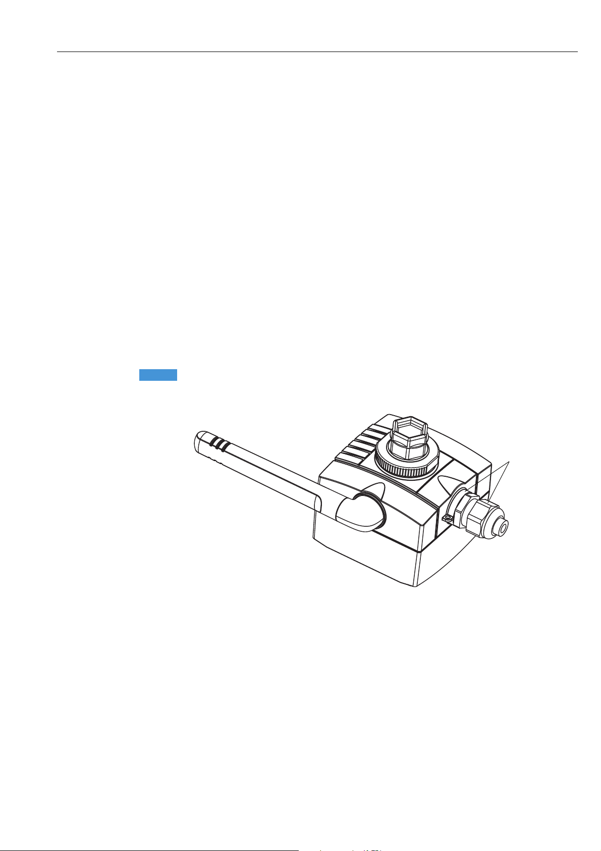
2 Identification . . . . . . . . . . . . . . . . . . . . .11
2.1 Unpacking the product . . . . . . . . . . . . . . . . . . . . . 11
2.1.1 Visual inspection . . . . . . . . . . . . . . . . . . . 11
2.1.2 Scope of delivery . . . . . . . . . . . . . . . . . . . . 11
2.1.3 Storage and transportation . . . . . . . . . . . 12
2.2 Nameplate . . . . . . . . . . . . . . . . . . . . . . . . . . . . . . . 12
2.3 Ordering information . . . . . . . . . . . . . . . . . . . . . . 13
3 Function and system design. . . . . . . . . 14
4 Installation . . . . . . . . . . . . . . . . . . . . . . . 15
4.1 Overview . . . . . . . . . . . . . . . . . . . . . . . . . . . . . . . . . 15
4.2 Installation conditions . . . . . . . . . . . . . . . . . . . . . 15
4.3 Positioning the SWA70 . . . . . . . . . . . . . . . . . . . . 15
4.4 Protection against lightning . . . . . . . . . . . . . . . . 16
4.5 Design . . . . . . . . . . . . . . . . . . . . . . . . . . . . . . . . . . . 16
4.6 Mounting on the field device . . . . . . . . . . . . . . . . 17
4.7 Remote mounting . . . . . . . . . . . . . . . . . . . . . . . . . 18
4.7.1 Wall mounting . . . . . . . . . . . . . . . . . . . . . 18
4.7.2 Pipe mounting . . . . . . . . . . . . . . . . . . . . . 20
4.8 Post-installation check . . . . . . . . . . . . . . . . . . . . . 21
5 Electrical installation of SWA70 with
battery unit . . . . . . . . . . . . . . . . . . . . . . .22
5.1 Power supply via battery unit . . . . . . . . . . . . . . . 22
5.2 Connecting the field device . . . . . . . . . . . . . . . . . 23
5.3 SWA70 terminals . . . . . . . . . . . . . . . . . . . . . . . . . 24
5.4 Wiring diagrams for battery unit . . . . . . . . . . . . 25
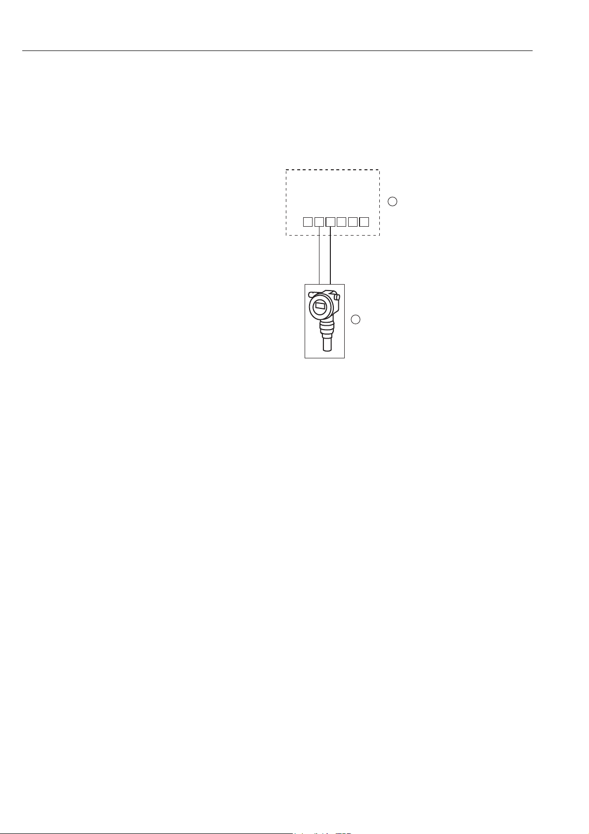
5.4.1 Two-wire field device with power
supplied by the adapter . . . . . . . . . . . . . . 25
5.4.2 Four-wire field device . . . . . . . . . . . . . . . 26
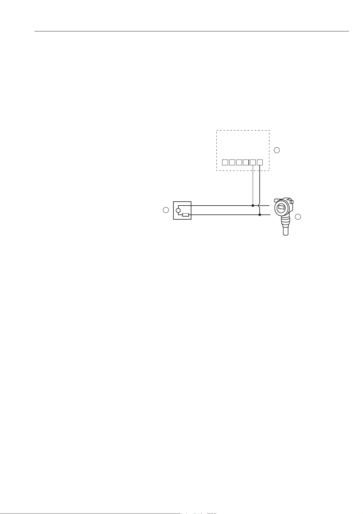
5.4.3 Field device in a closed-control loop
with a communication resistor . . . . . . . . 27
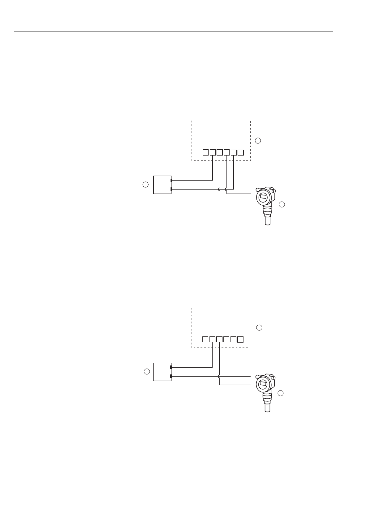
5.4.4 Field device in a closed-control loop
without a communication resistor . . . . . 28
5.5 Post-connection check . . . . . . . . . . . . . . . . . . . . . 29
6 Electrical installation of SWA70 with
wide range power unit . . . . . . . . . . . . . 30
6.1 Power supply via wide range power unit . . . . . . 30
6.2 Connecting the M12 socket . . . . . . . . . . . . . . . . . 32
6.3 Connecting the field device . . . . . . . . . . . . . . . . . 33
6.3.1 Cable specification . . . . . . . . . . . . . . . . . . 33
6.3.2 Wiring . . . . . . . . . . . . . . . . . . . . . . . . . . . . 33
6.4 SWA70 terminals . . . . . . . . . . . . . . . . . . . . . . . . . 34
6.5 Wiring diagrams for wide range power unit . . . 35
6.5.1 Two-wire field device with power supplied
by internal power supply system . . . . . . 35
6.5.2 Field device in a closed-control loop
with a communication resistor . . . . . . . . 36
6.5.3 Field device in a closed-control loop
without a communication resistor . . . . . 37
6.5.4 Four-wire field device . . . . . . . . . . . . . . . 38
6.5.5 Field devices in multidrop . . . . . . . . . . . . 39
6.6 Post-connection check . . . . . . . . . . . . . . . . . . . . . 39
7 Electrical installation of SWA70
with DC power unit . . . . . . . . . . . . . . . . 40
7.1 Power supply via DC power unit . . . . . . . . . . . . . 40
7.2 Connecting the M12 socket . . . . . . . . . . . . . . . . . 41
7.3 Connecting the field device . . . . . . . . . . . . . . . . . 42
7.3.1 Cable specification . . . . . . . . . . . . . . . . . . 42
7.3.2 Wiring . . . . . . . . . . . . . . . . . . . . . . . . . . . . 42
7.4 SWA70 terminals . . . . . . . . . . . . . . . . . . . . . . . . . 43
7.5 Wiring diagrams for DC power unit . . . . . . . . . . 44
7.5.1 Two-wire field device with power
supplied by adapter . . . . . . . . . . . . . . . . . 44
7.5.2 Four-wire field device . . . . . . . . . . . . . . . 45
7.5.3 Field device in a closed-control loop
with a communication resistor . . . . . . . . 46
7.5.4 Field device in a closed-control loop
without a communication resistor . . . . . 47
7.6 Post-connection check . . . . . . . . . . . . . . . . . . . . . 47
8 Operation . . . . . . . . . . . . . . . . . . . . . . . . 48
8.1 Display and operating elements – main PCB . . 48
8.1.1 Push button . . . . . . . . . . . . . . . . . . . . . . . 49
8.1.2 Display . . . . . . . . . . . . . . . . . . . . . . . . . . . . 49
8.2 Operating and display elements –
electronically controlled power supply units . . . 50
8.2.1 Push button . . . . . . . . . . . . . . . . . . . . . . . 50
8.2.2 Light emitting diodes . . . . . . . . . . . . . . . 51
8.3 Operating the field device . . . . . . . . . . . . . . . . . . 51
8.4 Local configuration and remote configuration . 51
Endress + Hauser 3
Page 4

WirelessHART adapter SWA70 Table of contents
9 Commissioning . . . . . . . . . . . . . . . . . . . 52
9.1 Connected HART field devices . . . . . . . . . . . . . . . 52
9.2 Inserting and connecting the battery unit . . . . . 53
9.3 Checks during commissioning . . . . . . . . . . . . . . . 54
10 Configuration and online
parameterization. . . . . . . . . . . . . . . . . . 55
10.1 Identification . . . . . . . . . . . . . . . . . . . . . . . . . . . . . 55
10.2 Wireless communication . . . . . . . . . . . . . . . . . . . 57
10.3 Wired communication . . . . . . . . . . . . . . . . . . . . . 59
10.4 Device variable mapping . . . . . . . . . . . . . . . . . . . 61
10.5 4-20 mA (application setting) . . . . . . . . . . . . . . 62
10.6 Burst mode (application setting) . . . . . . . . . . . . 64
10.7 Event notification (application setting) . . . . . . . 69
10.8 Field device power . . . . . . . . . . . . . . . . . . . . . . . . 74
10.9 Power option . . . . . . . . . . . . . . . . . . . . . . . . . . . . . 76
11 Additional DTM functions . . . . . . . . . . 78
11.1 Invoking the diagnostic parameters . . . . . . . . . . 78
11.1.1 Identification . . . . . . . . . . . . . . . . . . . . . . . 78
11.1.2 Wireless communication . . . . . . . . . . . . . 79
11.1.3 Wired communication . . . . . . . . . . . . . . . 80
11.1.4 Instrument health . . . . . . . . . . . . . . . . . . 80
11.1.5 Power Option . . . . . . . . . . . . . . . . . . . . . . 82
11.2 Simulation . . . . . . . . . . . . . . . . . . . . . . . . . . . . . . . 83
11.3 Access control . . . . . . . . . . . . . . . . . . . . . . . . . . . . 84
11.4 Updating the firmware . . . . . . . . . . . . . . . . . . . . . 85
11.5 Device DTM information . . . . . . . . . . . . . . . . . . . 86
11.6 Self-test . . . . . . . . . . . . . . . . . . . . . . . . . . . . . . . . . 86
12 Maintenance and repair. . . . . . . . . . . . 87
12.1 Replacing the battery unit . . . . . . . . . . . . . . . . . . 87
12.2 Return . . . . . . . . . . . . . . . . . . . . . . . . . . . . . . . . . . . 88
12.3 Disposal . . . . . . . . . . . . . . . . . . . . . . . . . . . . . . . . . 88
12.3.1 WirelessHART adapter . . . . . . . . . . . . . . 88
12.3.2 Battery unit . . . . . . . . . . . . . . . . . . . . . . . . 88
12.4 Contact addresses at Endress+Hauser . . . . . . . . 88
12.5 Accessories and spare parts . . . . . . . . . . . . . . . . . 89
13 Troubleshooting . . . . . . . . . . . . . . . . . . 90
14 Technical data . . . . . . . . . . . . . . . . . . . . 92
Index . . . . . . . . . . . . . . . . . . . . . . . . . . . . . . . . . 93
4 Endress + Hauser
Page 5

WirelessHART adapter SWA70 Revision history
Revision history
Product
version
1.00.xx BA061S/04/en/03.09 Original –
1.01.xx BA061S/04/en/11.09 All sections Amendments
1.02.xx BA061S/04/en/07.10 Section 8 Graphic with overview of burst
1.02.xx BA00061S/04/en/13.10 Section 2.2 Order number: approval
Manual Changes Remarks
Section 2 Storage
Section 4 Pipe mounting
Section 5 Terminal assignment,
2 additional wiring diagrams
Section 7 Connected HART field devices,
connection of the HART modem
and installation of the modem
driver, installation of the adapter
DTM, FieldCare DTM catalog
update
Section 8 Setting the burst mode
Section 9 Completely new
Section 10 Disposal
Section 11 Troubleshooting
Section 12 Technical data
mode
Section 8 Graphic with overview of event
notification
Table for device-specific event
screen
Section 11 Troubleshooting: Problem 3
amended
General Updated screenshots, minor
editorial changes
Section 8.4.3 Device-specific event mask: byte 6,
bit 0
Section 12.6 Fig. 12-1: Housing dimensions of
SWA70
1.02.xx BA00061S/04/en/14.11 Section 1.3 Hazardous area
Section 1.5, 12.5, 12.8 Additional telecommunication
approvals
Section 2.2 Amendments, Fig. 2-1: Nameplate
Section 2.3 New
Section 4.5.1 Reworked incl. Fig. 4-4
Section 4.5.2 Fig. 4-5
Section 5.2.2 Direct mounting, remote mounting
Section 7.3 Changed
2.00.xx BA00061S/04/en/15.12 All sections reworked New power supply units: "wide
range power unit", "intrinsically safe
power unit" and "solar module
connection".
Section 2.4 New radio approvals: "Brazilian
ANATEL radio approval" and
"Mexican COFETEL radio approval"
Section 5 New
Section 6.2 New
Sections 7 to 9 New DTM version SWA70 V2.xx.
Endress + Hauser 5
Page 6

Registered trademarks WirelessHART adapter SWA70
Product
version
2.00.xx BA00061S/04/en/16.13 General Updated screenshots, editorial
2.00.xx BA00061S/04/en/17.13 Section 2.2 Fig. 2-1 updated
2.00.xx BA00061S/04/en/18.14 General
2.30.xx BA00061S/04/en/19.15 General Simplified document structure.
2.40.xx BA00061S/04/en/20.16 General
Manual Changes Remarks
changes
Section 2.1.2 Scope of delivery
Section 5.1.1 Warning
Section 5.1.6 Connecting the M12 socket
Section 5.3.2, 5.3.3, 5.3.5 Note
Section 6.2.2 LED
Section 8.3.1 Order Code parameter
Section 8.3.3 Wake-up Detection parameter
Section 8.3.6 Setting the burst mode
Section 12.3 Cable specification
Section 2.3 Housing AISI 316L
Section 5.1 Warning notice and note
Section 5.1.2 Warning notice and Fig. 5-2
updated
Section 11 Troubleshooting: Problem 3
amended
Section 12.3 Power supply: current consumption
and power consumption
Section 12.6 Mechanical construction: weight
and degree of protection
Editorial changes
Section 12.5
Section 4.3
Telecommunication approval
"Technical data" section included in
Technical Information (TI).
Editorial changes
New Section: Positioning the
SWA70
NOTE
Note!
• For the valid connection data for the Ex versions, see the separate document "Safety
instructions (XA)". For the valid XA, see the nameplate.
Registered trademarks
HART®, WirelessHART
Registered trademarks of the HART Communication Foundation, Austin, USA
All other brand and product names are trademarks or registered trademarks of the
individual companies and organizations in question.
®
6 Endress + Hauser
Page 7

WirelessHART adapter SWA70 Safety instructions
1 Safety instructions
1.1 Designated use
The WirelessHART adapter SWA70 is a smart wireless module designed for the wireless
transmission of 4 to 20 mA HART signals from connected field devices to a WirelessHART
Fieldgate SWG70.
Information about the designated use of the connected field devices and the Fieldgate is
provided in the devices' individual operating manuals.
1.2 Installation, commissioning and operation
The WirelessHART adapter can be operated safely in compliance with the current technical
safety standards and the applicable EU guidelines. Field devices connected to the
WirelessHART adapter must also be operated in accordance with the current technical safety
standards and the applicable EU guidelines.
The WirelessHART adapter can be a source of danger if it is not installed correctly or if it is
used in applications for which it is not intended.
The WirelessHART adapter may only be installed, connected to the electricity supply,
commissioned, operated and maintained by trained, qualified specialists authorized to
perform such work by the facility's owner-operator. The specialist staff must have read and
understood these Operating Instructions and must follow the instructions they contain. The
devices may not be modified or repaired in any way.
These specifications also apply for the battery unit.
Note!
NOTE
Changes or modifications to the WirelessHART adapter that have not been expressly
approved by Endress+Hauser will render invalid the user’s right to operate the equipment.
1.3 Operational safety
Applications The WirelessHART adapter meets the requirements of the EU guidelines for the various
range of applications envisaged for the device. The permitted operating conditions must be
observed. See the Technical Information document for "WirelessHART Adapter SWA70"
(TI00026S).
Hazardous area A hazardous-area version (Ex version) of the WirelessHART adapter is available for use in
hazardous areas.
• The non-hazardous area version (non-Ex version) of the WirelessHART adapter is only
suitable for use outside hazardous areas.
• Depending on the particular approval, the intrinsically-safe and dust ignition-proof
versions of the device can be deployed in the corresponding hazardous areas.
The field devices that are connected to the hazardous-area versions of the WirelessHART
adapter must also be suitable for use in hazardous areas.
• If a WirelessHART adapter has been used in a non-Ex system it may no longer be installed
in an Ex system. This is because of the risk that the protective circuits might have become
overloaded accidentally and then not work correctly in the Ex system.
Endress + Hauser 7
Page 8

Safety instructions WirelessHART adapter SWA70
Please note the following if you use components in hazardous areas:
• Make sure that the operating staff in charge of installing and maintaining the device are
suitably trained and qualified.
• Ensure that all the system components have the appropriate safety certificates.
• Heed information provided in the device safety certificates, and comply with local and
national regulations.
Battery unit The WirelessHART adapter is designed to power a field device. In the battery version, power
is supplied via a high-power lithium-thionyl chloride battery unit. This has implications for
operational safety and storage. Please refer to the hazardous materials regulations described
in the Safety Data Sheet (www.endress.com).
Operation Caution!
A distance of at least 20 cm must be maintained at all times between the device antenna and
the body of the user or any other person in the vicinity irrespective of the application or use.
Maintenance
Warning!
• The housing of the WirelessHART adapter may not be opened in hazardous areas if dust
is present. The battery unit can only be replaced in a dusty atmosphere if adequate
ventilation ensures the environment is free of dust.
• Any tampering with the antenna, electronics or battery unit invalidates Endress+Hauser’s
warranty along with the telecommunications approval and hazardous area approval.
The housing of the hazardous-area version may be opened in the presence of gases in
hazardous areas for the purpose of commissioning the device and replacing the power
supply unit.
The housing may be opened outside hazardous areas for the purpose of commissioning the
device and replacing the power supply unit.
WirelessHART adapters with an electronically controlled power supply unit do not require
any maintenance. In the case of WirelessHART adapters with a battery unit, the battery unit
is the only component that may be replaced. The WirelessHART adapter may not be
repaired.
If the device is faulty or malfunctions, return the device to Endress+Hauser. Follow the
instructions outlined in “Return” on page 88. In the case of devices with a battery unit, the
battery unit must be removed before the device is returned.
8 Endress + Hauser
Page 9

WirelessHART adapter SWA70 Safety instructions
1.4 Declaration of Conformity
All the Declarations of Conformity can be found on www.endress.com
CE mark The WirelessHART adapter SWA70 meets the legal requirements of the relevant
EC guidelines. Endress+Hauser confirms that the WirelessHART adapter SWA70 has been
successfully tested by affixing to it the CE mark. An EC Declaration of Conformity has been
issued for the hazardous area versions and non-hazardous area versions.
1.5 Technical improvement
Endress+Hauser reserves the right to make technical improvements to the hardware and
software anytime without prior notice. Such improvements are not documented if they do
not affect the operation of the device. A new version of the Operating Instructions is created
if the improvements affect operation.
Endress + Hauser 9
Page 10
Safety instructions WirelessHART adapter SWA70
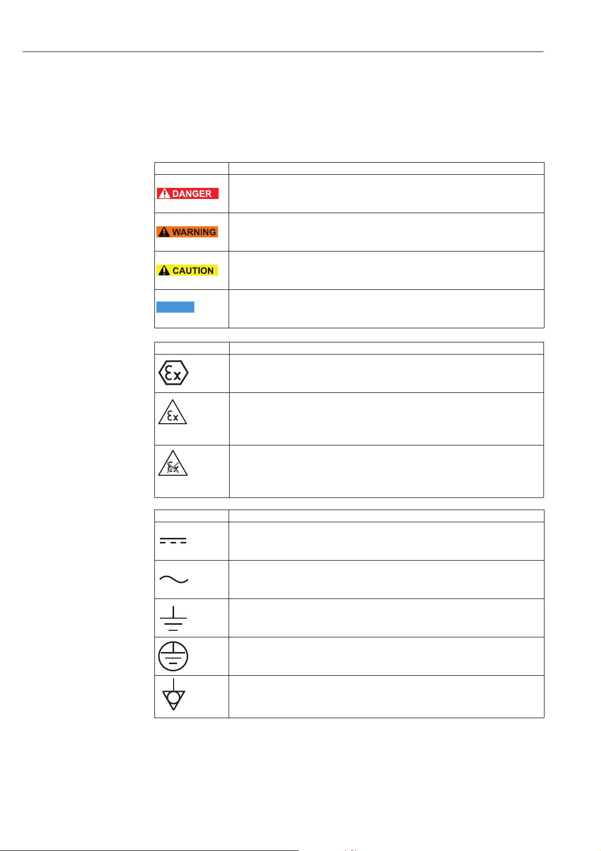
1.6 Conventions used in this manual
Typographical emphasis and special symbols have been used to provide a clear structure to
the contents of these Operating Instructions and to highlight important information.
Pay particular attention to the safety conventions and icons used in these Operating
Instructions.
Safety instructions
Type of protection
Symbol Meaning
Danger!
This symbol alerts you to dangerous situations. Failure to heed the instructions will result
in a serious or fatal injury.
Warning!
This symbol alerts you to dangerous situations. Failure to heed the instructions can result in
a serious or fatal injury.
Caution!
This symbol alerts you to dangerous situations. Failure to heed the instructions can result in
a mild to medium injury.
Note!
NOTE
Symbol Meaning
This symbol refers you to procedural information and other facts that do not result in
physical injury.
Explosion-protected, type-examined equipment
If the device has this symbol embossed on its nameplate, it can be used in a hazardous area
or a non-hazardous area, depending on the approval.
Hazardous area
This symbol is used in the drawings of these Operating Instructions to indicate hazardous
areas.
– Devices located in hazardous areas, or cables for such devices, must have appropriate
explosion protection.
Safe area (non-hazardous area)
This symbol is used in the drawings of these Operating Instructions to indicate nonhazardous areas.
– Devices in the non-hazardous area also have to be certified if connecting cables lead into
the hazardous area.
Electrical symbols
Symbol Meaning
Direct current
A terminal to which DC voltage is applied or through which direct current flows.
Alternating current
A terminal to which alternating voltage (sine-wave) is applied or through which
alternating current flows.
Ground connection
A grounded terminal which, as far as the operator is concerned, is already grounded via a
grounding system.
Protective ground connection
A terminal which must be connected to ground prior to connecting any other terminals.
Equipotential connection
A connection that has to be connected to the plant grounding system: This may be a
potential equalization line or a star grounding system depending on national practice or
company codes of practice.
10 Endress + Hauser
Page 11

WirelessHART adapter SWA70 Identification
2 Identification
2.1 Unpacking the product
2.1.1 Visual inspection
When unpacking the product:
• Check the packaging for visible signs of damage in transit.
• Remove the packaging carefully in order to prevent any damage.
• Keep the original packaging in case you need to transport the WirelessHART adapter
another time.
• Keep the documentation supplied with the adapter in a safe place.
2.1.2 Scope of delivery
Check that the delivery is undamaged and that nothing is missing before you start
commissioning.
The delivery comprises:
• WirelessHART adapter
• For versions "prepared for battery unit": battery unit for WirelessHART adapter
• For versions with electronically controlled power supply unit: M12 socket, ferrite sleeve
• Quick Guide
Optional:
• Wall/pipe mounting bracket
• Cable for electrically connecting the WirelessHART adapter to a field device
• Double-threaded connection adapter: M20 or G 1/2 with two seals, NPT 1/2 or NPT 3/4
with one seal
• Cable gland with one seal
• FieldCare Device Setup DVD
• Folder containing important documents (including safety documents)
Warning!
• If you discover that the battery unit is damaged, proceed as described in the Safety Data
Sheet.
• If you discover that the WirelessHART adapter is damaged, the device may not be put into
operation.
In this case, contact your Endress+Hauser sales partner. Where possible, return the device
to Endress+Hauser in its original packaging.
Endress + Hauser 11
Page 12
Identification WirelessHART adapter SWA70
2.1.3 Storage and transportation
While the WirelessHART adapter is a robust device, appropriate precautions must be taken
to ensure proper storage and transportation:
Storage Comply with permitted storage temperature range. See the Technical Information document
for "WirelessHART Adapter SWA70" (TI00026S).
WirelessHART adapter with battery unit: store the WirelessHART adapter with the battery
unit disconnected.
Store the WirelessHART adapter and/or battery unit as follows:
• Store in a cool, aerated and dry environment
• Do not store near sources of heat, naked flames, food and beverages.
Transportation When transporting the WirelessHART adapter it must be protected against strong
vibrations or shock.
Warning!
• High-power lithium-thionyl chloride batteries are classified as a Class 9 hazardous
material (HAZMAT Class 9: Miscellaneous). Please refer to the hazardous materials
regulations provided in the Safety Data Sheet.
2.2 Nameplate
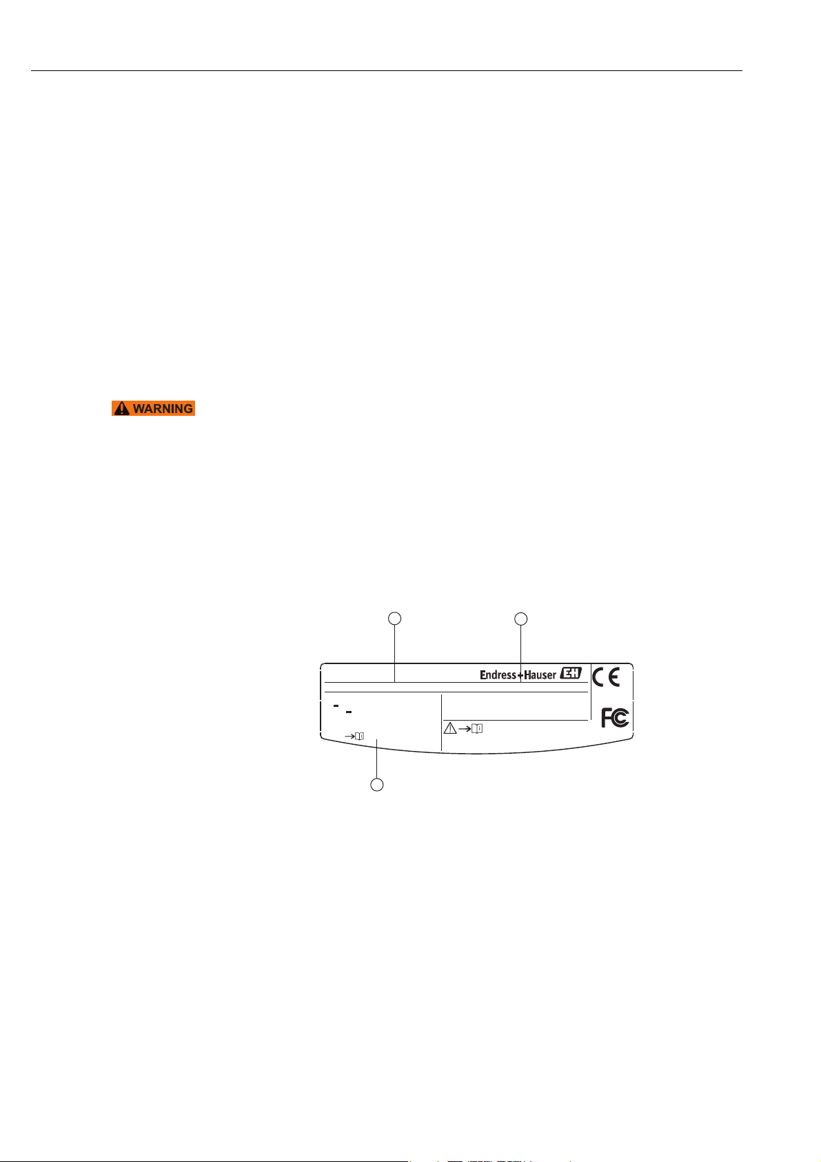
The nameplate is located on the side of the WirelessHART adapter, and contains all the
important information such as the order code, serial number and radio approvals. Additional
information about the radio approval is provided on a separate adhesive label.
See figure 2-2 on page13.
1
Made in Germany, D-79689 Maulburg
WirelessHART Adapter SWA70
Order Code
U: ~ 24-230 V, P: ≤ 12 VA 50/60 Hz
U: 24-230 V, P: ≤ 7 W
Uout 30 V≤
-40°C
1 Order number
2 Serial number
3 Radio and approval information
SWA70-AA1A2A1+Z1
≤ Tamb ≤ +80°C
Contains: FCC ID: SJC - M1240
IC: 5853A-M2140
3
2.4 GHz
Fig. 2-1: Nameplate (example)
Dat.: 2013-05
2
Ser.: XXXXXXXXXXX
IP65/ IP 66
Type4 Encl.
12 Endress + Hauser
Page 13

WirelessHART adapter SWA70 Identification
Radio approvals
R
202WW09117711
CMMIT ID 2011DJ5309
Fig. 2-2: Position of adhesive label containing radio approval information (example)
2.3 Ordering information
Detailed information about the product structure is available:
• In the Product Configurator on the Endress+Hauser website: www.endress.com
Select country Products System components & recorders
Wireless communication WirelessHART adapter SWA70
Product page function: Configure this product
• From your Endress+Hauser Sales Center: www.addresses.endress.com
Endress + Hauser 13
Page 14
Function and system design WirelessHART adapter SWA70
3 Function and system design
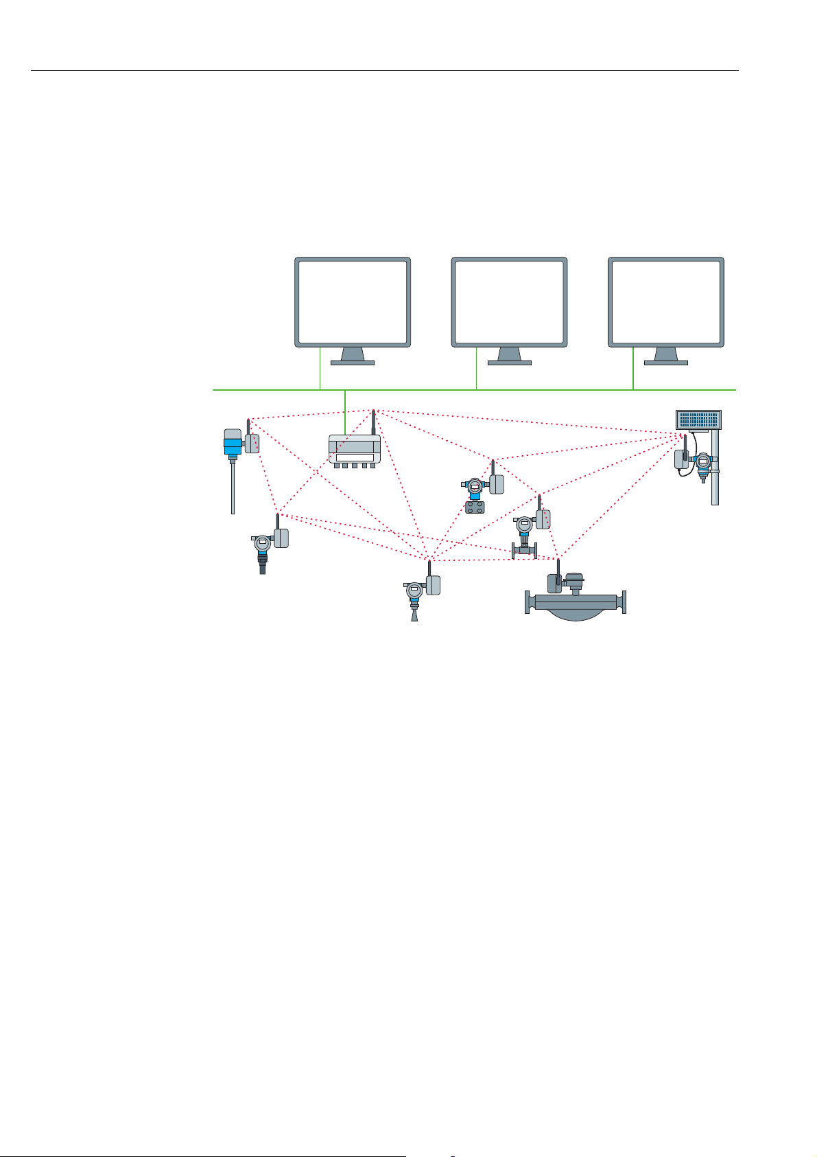
The WirelessHART adapter is a smart wireless module that connects HART and 4 to 20 mA
field devices to a WirelessHART network. The WirelessHART adapter sends the
measurement and diagnostics information acquired from the field device to the
WirelessHART Fieldgate in the form of radio signals. The Fieldgate receives this information
and makes it available in the system network.
1
2
4
4
4
4
Fig. 3-1: WirelessHART network
3 WirelessHART Fieldgate
4 Field devices with wireless
4
4
1 Host applications
2 Ethernet
Ethernet
3
The WirelessHART network is self-organizing. After installation and configuration, every
WirelessHART adapter is able to recognize its neighbors. It detects the strength of the radio
signal, receives frequency, timing and path information, and then establishes a connection
to neighbors in the wireless network. In this way, the network is organized without the need
for the user to make any settings.
The standard version of the WirelessHART adapter has a plastic housing, and the
hazardous-area version (Ex version) is available with either an aluminum housing, steel
316L or plastic housing. If a field device is connected to an Ex version, it too must have an
appropriate approval for use in hazardous areas (Ex approval).
The WirelessHART adapter can be powered in one of three ways: with a battery unit, a wide
range power unit, or a DC power unit. The field device can be powered either via the power
supply of the WirelessHART adapter or via a separate DC voltage power unit or remote I/O.
Two-wire and four-wire field devices can be connected.
The WirelessHART adapter can also be used as a repeater. In this case, the adapter does not
supply power to any field device.
14 Endress + Hauser
Page 15

WirelessHART adapter SWA70 Installation
4 Installation
4.1 Overview
The WirelessHART adapter can be installed mechanically in three different ways:
• Directly on the field device
• At a distance from the field device, but connected by a cable (remote mounting)
• As a repeater, i.e. without a field device
Various replaceable connection adapters can be screwed onto the cable entry of the
WirelessHART adapter depending on the use and the field device connection.
Depending on the order, the following installation accessories may be supplied with the
WirelessHART adapter:
• Connection adapter for mounting on a field device with M20 connection
• Connection adapter for mounting on a field device with G 1/2 connection
• Connection adapter for mounting on a field device with NPT 1/2 connection
• Connection adapter for mounting on a field device with NPT 3/4 connection
• Cable gland for remote mounting with a cable
• Mounting bracket as an accessory for mounting on a wall or pipe
NOTE
4.2 Installation conditions
The WirelessHART adapter is approved for use in locations exposed to weather conditions.
See the Technical Information document for "WirelessHART Adapter SWA70" (TI00026S).
Note!
In order to avoid attenuation of the electromagnetic waves and any resulting impairment in
the operation of the WirelessHART adapter, the following must be observed when mounting
the adapter:
• When mounting the adapter at a distance from the field device (remote mounting), the
antenna must be at least 6 cm away from a wall or post.
• The antenna of the WirelessHART adapter should never be located between a wall/post
and the housing.
• There must be a distance of at least 6 cm between the antenna and any metal material
running parallel to it.
• Align the antenna so that it is completely vertical.
• If multiple WirelessHART adapters are used, ideally there should not be any walls or
similar constructs between the adapters in order to guarantee an optimum wireless
network.
4.3 Positioning the SWA70
Install the WirelessHART gateway first, before installing other WirelessHART devices. This
way you can check for proper operation of new devices as they are installed. Nevertheless,
consider the location of future WirelessHART devices that will be routed through the
WirelessHART gateway to ensure good connectivity.
Guidelines for Planning a WirelessHART Network
• A line-of-sight between communication partners always is desirable. If a line-of-sight is
not possible, the obstacles should not be massive and the partners should be more to the
edge of an obstacle to allow the wave to "bend" around it (diffraction effect).
• Install wireless devices at least 1m above the ground.
• Make sure that the device's antenna is aligned vertically for best results.
• Make sure that a minimum of 2 other WirelessHART devices are well within the antenna
range of the device.
Endress + Hauser 15
Page 16
Installation WirelessHART adapter SWA70
• Do not position WirelessHART devices directly below or above each other. They would be
outside each other's antenna range.
• Install WirelessHART devices at least 1 m away from each other.
• Antennas must be at least 6 cm away from any wall or any metallic material running
parallel to it.
• Position the device as far away as possible from metal surfaces or walls containing metal.
There should be as little metal close to the device as possible.
• Do not position other 2.4 GHz devices like cordless phone bases or WLAN routers near
WirelessHART devices. Keep in mind other wireless networks using the same frequency
spectrum (WLAN, Bluetooth, etc.). Wireless technologies used in an industrial
environment must be able to coexist without disrupting each other.
4.4 Protection against lightning
Take the following measures to protect the WirelessHART adapter from a lightning strike:
• Do not mount the WirelessHART Adapter at the highest point in the plant.
• WirelessHART Adapter with metal housing: connect protective ground to protective
ground connection of the housing. The protective ground connection is located on the
inside and outside of the housing. Protective ground in 2.5 mm2.
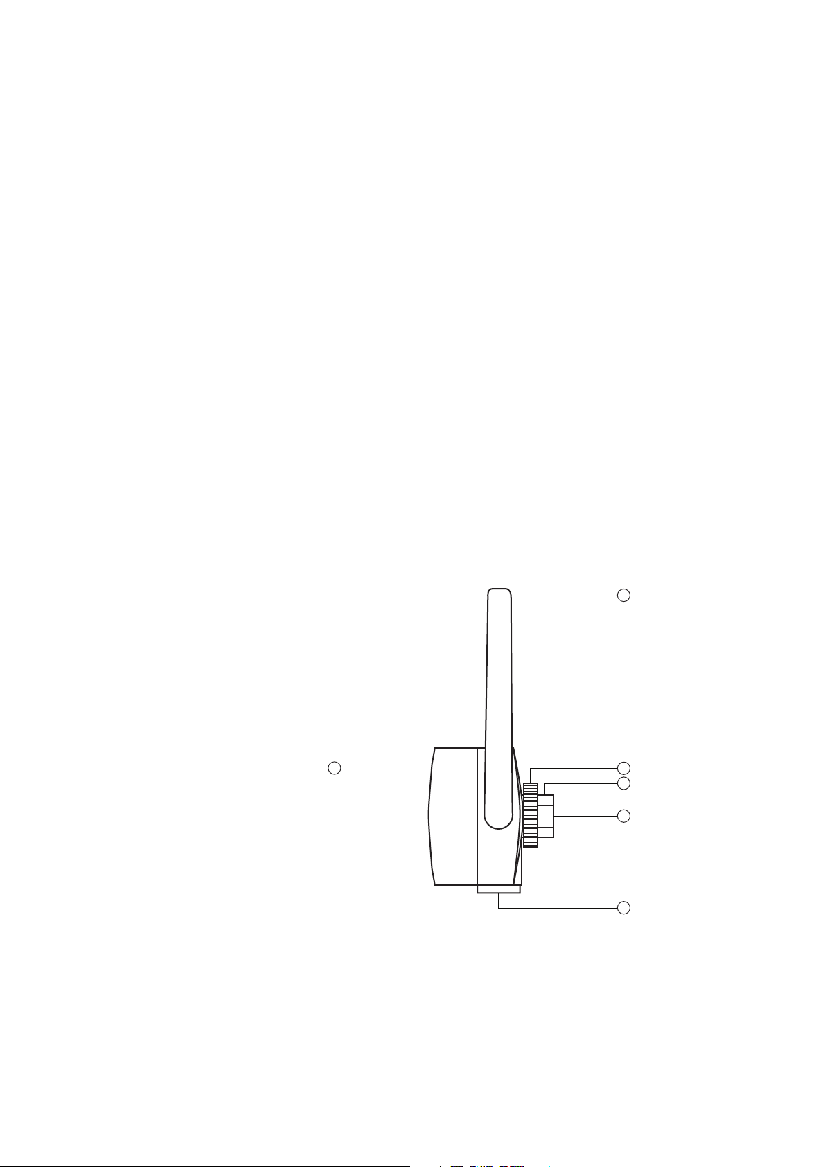
4.5 Design
For housing dimensions, see the Technical Information document for "WirelessHART
Adapter SWA70" (TI00026S).
1
6
2
3
4
5
Fig. 4-1: Side view of the housing
1 Antenna
2 Fixing nut
3 Cable entry
4 Primary cable entry for installation on field device,
internal thread M20x1.5
5 Secondary cable entry for remote mounting or for
WirelessHART adapters with controlled power
supply units for external power supply, internal
thread M20x1.5
6 Cover of adapter with battery compartment
16 Endress + Hauser
Page 17

WirelessHART adapter SWA70 Installation
4.6 Mounting on the field device
You require the following tools to mount the WirelessHART adapter on the field device:
• Wrench 24 mm across flats
• Wrench 42 mm across flats
1
zu
zu
auf
auf
NOTE
2
3
Fig. 4-2: Mounting on the device
1 Double-threaded connection adapter
2 Fixing nut
3 Cable entry
Note!
• By loosening the fixing nut you can rotate the cable entry without having to turn the
housing of the WirelessHART adapter.
Proceed as follows to mount the WirelessHART adapter on the field device:
1. Remove the sealing cap on the cable entry.
2. Fit a seal on either side of the double-threaded connection adapter as far as the end of
the thread.
3. Using the 24mm wrench, screw the connection adapter into the field device coupling
(torque 5 Nm).
4. Release the fixing nut of the WirelessHART adapter.
5. Fit the cable entry of the WirelessHART adapter onto the connection adapter screwed
into the field device and tighten the cable entry using the 24mm wrench (torque 5 Nm).
6. Align the adapter if necessary.
7. While holding the cable entry with the 24mm wrench, tighten the fixing nut using the
42mm wrench (torque 7 Nm).
Endress + Hauser 17
Page 18
Installation WirelessHART adapter SWA70
4.7 Remote mounting
Remote mounting - where the field device and adapter are mounted at a distance from one
another - can be required in various situations, such as when:
• There is not enough space to mount the adapter on the field device.
• Signal reception at the field device is too weak for correct operation.
• The field device is subject to vibration above the recommended limit.
The WirelessHART adapter can be mounted on a wall, post or other object using the "wall/
pipe mounting bracket". In this case, the WirelessHART adapter and the field device are
connected via a connecting cable and cable glands.
The "wall/pipe mounting bracket" and the cable glands are accessories. The connecting cable
is not included in the scope of delivery.
4.7.1 Wall mounting
You require the following tools to mount the WirelessHART adapter on the wall:
• Wrench 24 mm across flats
• Wrench 42 mm across flats
• Wrench 8 mm across flats
• Size 4 Allen screw
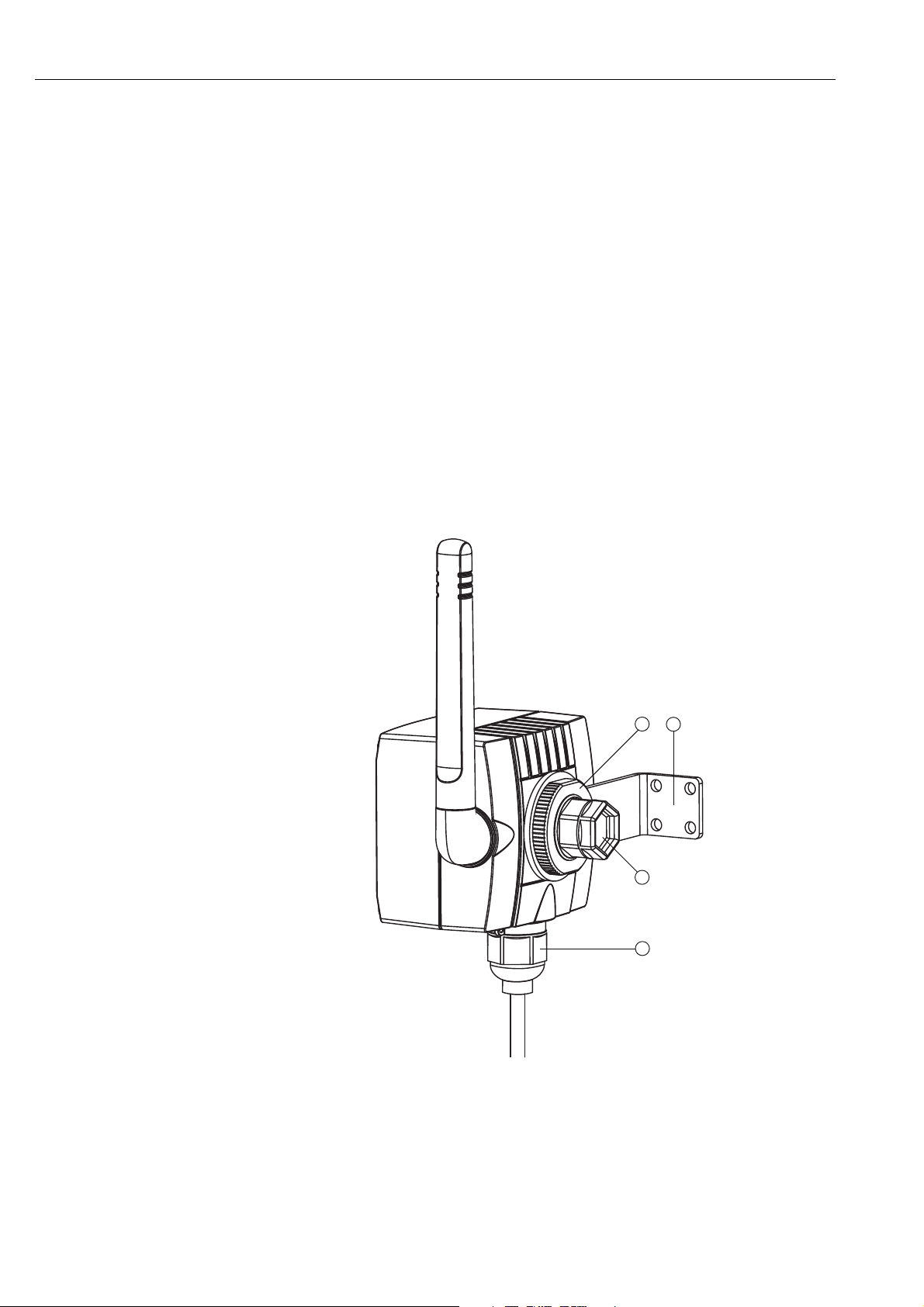
1 Fixing nut
2 Angle bracket
1
2
3
4
Fig. 4-3: Remote mounting with angle bracket for wall mounting
3 Sealing cap on cable entry (primary cable outlet).
4 Cable gland on secondary cable outlet for remote mounting or
for WirelessHART adapters with controlled power supply
units for external power supply
18 Endress + Hauser
Page 19

WirelessHART adapter SWA70 Installation
Proceed as follows to mount the WirelessHART adapter on a wall:
1. Screw the angle bracket onto the wall at a suitable point.
2. Unscrew the fixing nut in a counterclockwise direction.
3. Guide the cable entry of the WirelessHART adapter through the opening of the angle
bracket in such a way that the antenna is as far away from the wall as possible.
4. Fit the fixing nut on the cable entry and tighten the fixing nut in a clockwise direction so
that the WirelessHART adapter sits loosely.
5. Align the adapter in such a way that the antenna is vertical at the end of the mounting
procedure.
6. Hold the cable entry in position with a wrench and tighten the fixing nut.
7. Preferably use the secondary cable outlet to connect to the field device.
Endress + Hauser 19
Page 20
Installation WirelessHART adapter SWA70
4.7.2 Pipe mounting
You require the following tools to mount the WirelessHART adapter on a pipe:
• Wrench 42 mm across flats
• Wrench 24 mm across flats
• Wrench 10 mm across flats
• Wrench 8 mm across flats
• Size 4 Allen screw
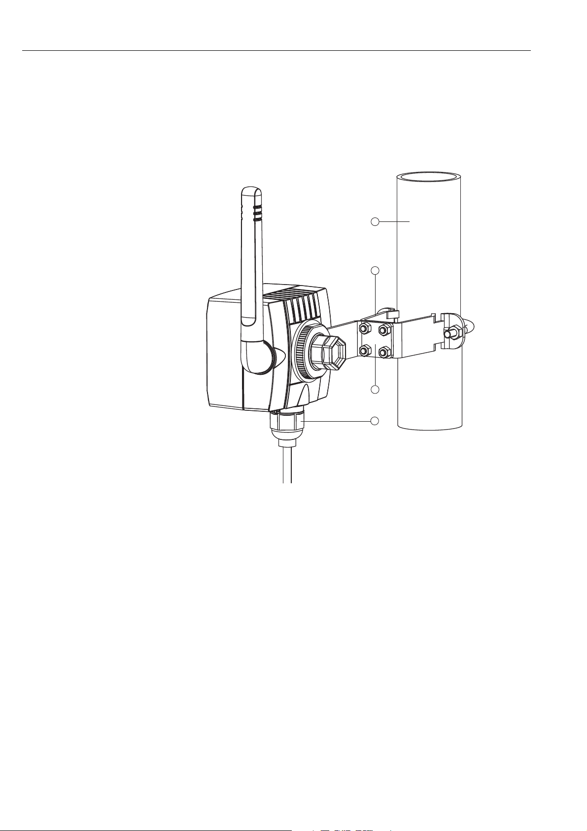
1
2
3
4
Fig. 4-4: Remote mounting on a pipe with a mounting bracket
1 Pipe with a maximum diameter of 65mm
2 Fixing bracket
3 Angle bracket
4 Cable gland on secondary cable outlet for remote
mounting or for WirelessHART adapters with
controlled power supply units for external power
supply
Proceed as follows to mount the WirelessHART adapter on a pipe using the "wall/pipe
mounting bracket":
1. Screw the fixing bracket onto the pipe at a suitable point and tighten the nuts
(minimum torque 5 Nm).
2. Screw the angle bracket onto the fixing bracket with the four Allen screws supplied
(torque 4 Nm).
3. Fasten the WirelessHART adapter on the angle bracket. See “Wall mounting” on
page 18.
20 Endress + Hauser
Page 21

WirelessHART adapter SWA70 Installation
4.8 Post-installation check
After mounting the WirelessHART adapter, perform the following final checks:
• Is the WirelessHART adapter damaged (visual inspection)?
• Does the WirelessHART adapter meet the specifications for the place of operation,
including the ambient temperature, relative humidity etc.?
• WirelessHART adapter with metal housing: has the WirelessHART been correctly
grounded?
• Is the antenna correctly aligned?
• Has the WirelessHART adapter been mounted at a sufficient distance from a wall, pipe or
post?
• Has the wall/pipe mounting bracket been correctly mounted?
• Are the cable entry and fixing nut securely tightened?
• Have the lightning protection measures indicated in chapter 4.3 been taken into
consideration?
Endress + Hauser 21
Page 22
Electrical installation of SWA70 with battery unit WirelessHART adapter SWA70
5 Electrical installation of SWA70 with battery
unit
For the technical data, such as the cable specification, see the Technical Information
document for "WirelessHART Adapter SWA70" (TI00026S).
5.1 Power supply via battery unit
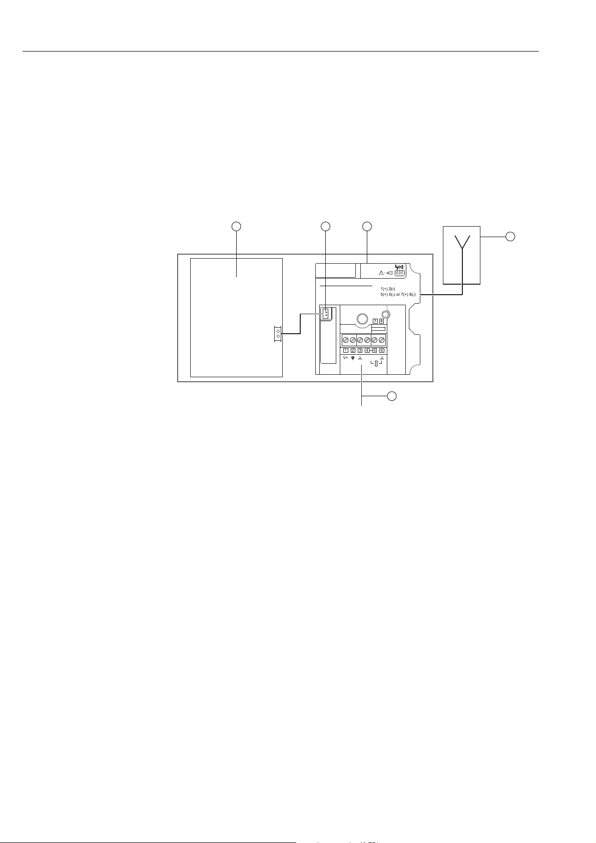
The WirelessHART adapter with the battery unit is powered by the internal battery.
3
Fig. 5-1: Block circuit diagram of power supply via battery unit
1 Antenna
2 Field device connection, see chapter "Connecting the
field device" on page23.
4
Common types of connection:
2-wire device, adapter powered
HART modem/Handheld
Please see manual for more types
power
5
1
2
3 Battery unit
4 Internal DC power supply
5 WirelessHART adapter main PCB
22 Endress + Hauser
Page 23
WirelessHART adapter SWA70 Electrical installation of SWA70 with battery unit
5.2 Connecting the field device
You can mount the WirelessHART adapter either directly on the field device or at a distance
from the field device on a wall or post using a bracket.See “Wall mounting” on page 18.
See “Pipe mounting” on page 20.
Mounted directly on the
Proceed as follows to mount directly on the field device:
field device
1. Open the housing of the WirelessHART adapter.
2. Guide the cable through the cable entry.
3. Wire the cable with the appropriate terminals of the WirelessHART adapter.
See “Wiring diagrams for battery unit” on page 25.
4. Wire the field device as described in the operating manual for the field device in
question.
5. If the field device is not put into operation immediately after wiring, close the housing of
the WirelessHART adapter and the connection compartment of the field device. Tighten
the housing screws of the WirelessHART adapter with a torque of 0.6 Nm.
Remote mounting For WirelessHART adapters with a battery unit, we recommend you perform the wiring
between the WirelessHART adapter and the field device via the secondary cable entry. The
secondary cable entry is located on the bottom of the WirelessHART adapter.
Note!
NOTE
• If the primary cable entry must be used, make sure that the water does not flow along the
cable and enter the housing.
Secondary cable entry
with cable gland
M20x1.5
Fig. 5-2: Cable insertion through the secondary cable entry
Proceed as follows to insert a cable into the housing through the secondary cable entry:
1. Remove the sealing cap from the secondary cable entry of the WirelessHART adapter.
2. Screw the M20x1.5 cable gland into the thread of the cable entry (torque 3.25 Nm).
3. Turn the coupling nut slightly in the counterclockwise direction to release the tension
on the cable gland.
Endress + Hauser 23
Page 24

Electrical installation of SWA70 with battery unit WirelessHART adapter SWA70
4. Open the housing of the WirelessHART adapter.
5. Guide the cable through the cable gland and into the housing.
6. Wire the cable with the appropriate terminals of the WirelessHART adapter.
See “Post-connection check” on page 47.
7. Tighten the coupling nut of the cable gland (torque 3.5 Nm).
8. If the field device is not put into operation immediately after wiring, close the housing of
the WirelessHART adapter and the connection compartment of the field device. Tighten
the housing screws of the WirelessHART adapter with a torque of 0.6 Nm.
5.3 SWA70 terminals
For the permitted connection data, see the Technical Information document for
"WirelessHART Adapter SWA70" (TI00026S).
Note!
NOTE
• On account of the internal communication resistor, the power supply of the field device
varies depending on the set current and terminal voltage.
For connection purposes, the WirelessHART adapter contains a terminal block with screw
terminals 1-6 and the 2 terminals 7 and 8.
Loop current
measurement
and HART
communication
123 4
Fig. 5-3: Assignment of terminals
Terminals Description
1 and 2 • Field device power supply
• 4 to 20 mA/HART input
2 and 3 4 to 20 mA/HART input
4 or 5 High-impedance HART input/output terminals
3 or 6 High-impedance HART input/output terminals and ground
7 and 8 HART modem connection
HART
communication
7
8
5
6
Loop current
measurement
1 – 2
Loop current
measurement
2 – 3
24 Endress + Hauser
Page 25

WirelessHART adapter SWA70 Electrical installation of SWA70 with battery unit
5.4 Wiring diagrams for battery unit
For the WirelessHART adapter with a battery unit, the following options are available to
electrically connect a field device as a:
• Two-wire field device with power supplied by the adapter: see page 25.
• Four-wire field device: see page 26.
• Field device in a closed-control loop with a communication resistor: see page 27.
• Field device in a closed-control loop without a communication resistor: see page 28.
5.4.1 Two-wire field device with power supplied by the adapter
The following functions are possible with this connection version:
• Power supply to the field device
• Current measurement in the 4 to 20 mA range
• Digital HART communication if this is supported by the field device.
Connect the WirelessHART adapter as illustrated below:
.
NOTE
1
1 2 3 4
+
Fig. 5-4: WirelessHART adapter with battery unit –
connection of a two-wire field device with power supplied by the adapter
1 WirelessHART adapter terminals 2 Field device
5
6
–
2
Note!
To extend the battery life, we recommend you operate the HART field device in the
multidrop mode. For this purpose, set the address of the field device to 1.
Endress + Hauser 25
Page 26
Electrical installation of SWA70 with battery unit WirelessHART adapter SWA70
5.4.2 Four-wire field device
The following functions are possible with this connection version:
• Current measurement in the 4 to 20 mA range
• Digital HART communication if this is supported by the field device.
Connect the WirelessHART adapter as illustrated below:
1
1 2 3 4
+
Fig. 5-5: WirelessHART adapter with battery unit –
connection of a four-wire field device
1 WirelessHART adapter terminals 2 Four-wire field device
5
6
–
2
26 Endress + Hauser
Page 27
WirelessHART adapter SWA70 Electrical installation of SWA70 with battery unit
5.4.3 Field device in a closed-control loop with a communication resistor
The WirelessHART adapter can be connected to an existing installation comprising a HART
field device and a power supply system that includes a communication resistor.
The following functions are possible with this connection version:
• Digital HART communication in multidrop mode
Connect the WirelessHART adapter as illustrated below:
1
3
Fig. 5-6: WirelessHART adapter with battery unit –
connection of a field device in a closed-control loop with a communication resistor
1 WirelessHART adapter terminals
2 Field device
1 2 3 4
+
––
5
6
+
2
3 PLC, remote I/O or DC voltage power unit with a
communication resistor
Endress + Hauser 27
Page 28
Electrical installation of SWA70 with battery unit WirelessHART adapter SWA70
5.4.4 Field device in a closed-control loop without a communication resistor
The following functions are possible with this connection version:
• Current measurement in the 4 to 20 mA range
• Digital HART communication if this is supported by the field device.
The following connection version is recommended if installing with a two-wire cable:
1
1 2 3 4
5
6
+
3
–
Fig. 5-7: WirelessHART adapter with battery unit – connection of a field device
in a closed-control loop without a communication resistor, with a two-wire cable
1 WirelessHART adapter terminals
2 Field device
If installing with just one signal cable (e.g. common ground for return cable), connect the
WirelessHART adapter as illustrated below:
3 PLC, remote I/O or DC voltage power unit without
a communication resistor
–
+
1
2
1 2 3 4
5
6
+
3
–
–
+
Fig. 5-8: WirelessHART adapter with battery unit –
connection of a field device in a closed-control loop without a communication resistor, with one signal cable
1 WirelessHART adapter terminals
2 Field device
28 Endress + Hauser
3 PLC, remote I/O or DC voltage power unit without
a communication resistor
2
Page 29

WirelessHART adapter SWA70 Electrical installation of SWA70 with battery unit
Note!
NOTE
• The connection is established via the internal 270 resistor.
• The connection circuits in fig. 5-7 and fig. 5-8 are electrically identical as terminal 4 is
connected internally to terminal 5.
5.5 Post-connection check
After wiring the WirelessHART adapter, perform the following final checks:
• Is the assignment of the terminals correct?
• Is the cable gland sealed tightly?
Endress + Hauser 29
Page 30

Electrical installation of SWA70 with wide range power unit WirelessHART adapter SWA70
6 Electrical installation of SWA70 with wide
range power unit
For the technical data, such as the cable specification, see the Technical Information
document for "WirelessHART Adapter SWA70" (TI00026S).
6.1 Power supply via wide range power unit
Danger!
Risk of electric shock! Any contact with live parts presents a potentially life-threatening
hazard.
• Work must only be performed by certified electrical technicians.
• Before opening the WirelessHART adapter, switch off the power supply and prevent it
from being switched on again. Check that the unit is not live.
• Do not wire the WirelessHART adapter if it is live.
• Ground the WirelessHART adapter with the metal housing. For this, connect the 2.5 mm
protective conductor to the protective ground connection. The protective ground
connection is located on the inside and outside of the housing.
2
NOTE
Warning!
• The WirelessHART adapter must be protected at the customer's site by an external 1A
slow-blow backup fuse, designed for min. 250 V AC, and approved for the particular
application.
Note!
• Guide the power supply cable through the ferrite sleeve supplied. Fix the ferrite sleeve at
a distance of 5 cm to 30 cm to the adapter.
• If EMC emissions Class B are required for the operation in the country of destination,
a line filter must be added.
30 Endress + Hauser
Page 31

WirelessHART adapter SWA70 Electrical installation of SWA70 with wide range power unit
The WirelessHART adapter with the wide range power unit is connected to the power supply
via the M12 connector. See “Connecting the M12 socket” on page 32.
5
Main board
supply
Power
Charge
Ready
LED on
+
–
Common types of connection:
2-wire device, adapter powered
HART modem/Handheld
Please see manual for more types
power
Field device
supply output
UNPS
Wide-range power supply
Serial number
abxxxx24yyy
Date: JJJJ-MM
4
3
Fig. 6-1: Block circuit diagram of power supply via wide range power unit
1 Antenna
2 Alternative connection via Pin 2 and Pin 3, see
figure 6-7 on page37 or Pin 5 and Pin 6, see
figure 6-6 on page36.
3 Suitable back-up fuse, provided by the customer
onsite
4 Connection for power supply of wide range power
unit
6
7
2
5 Preferred connection for field devices, up to four
field devices possible in multidrop.
See figure 6-9 on page39.
6 Internal DC power supply
7 WirelessHART adapter main PCB
1
Endress + Hauser 31
Page 32
Electrical installation of SWA70 with wide range power unit WirelessHART adapter SWA70
6.2 Connecting the M12 socket
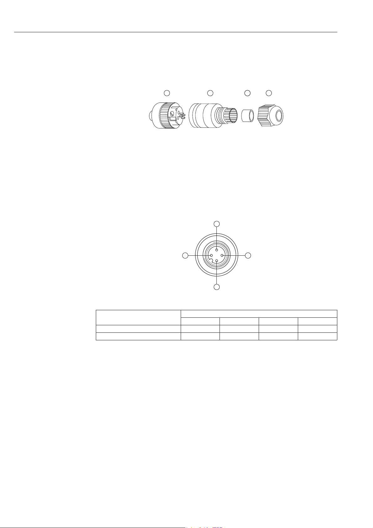
A WirelessHART adapter with the wide range power unit is connected to the power supply
via the M12 connector. An M12 socket is included in the delivery.
Disassembly and assembly
PIN assignment
of M12 socket
1
Fig. 6-2: Disassembling and assembling the M12 socket
1 Socket insert with terminals
2 Coupling sleeve
2
3 Seal
4 Coupling nut
343
1. Insert the seal into the narrower of the two openings of the coupling sleeve.
2. Guide the cable through the coupling nut and coupling sleeve.
3. Connect the cable in accordance with the PIN assignment. Tighten the screws in the
socket insert.
3
2
4
1
Fig. 6-3: PIN assignment of M12 socket
Power supply version PIN assignment
1234
Wide range power unit 24-230 V AC L n.c. N n.c.
Wide range power unit 24-230 V DC + n.c. – n.c.
4. Screw together the socket insert and the coupling sleeve. For this purpose turn the
knurled head screw while holding the coupling sleeve steady.
5. Screw down the coupling nut.
32 Endress + Hauser
Page 33

WirelessHART adapter SWA70 Electrical installation of SWA70 with wide range power unit
6.3 Connecting the field device
You require the following tools for the electrical installation of the WirelessHART adapter:
• Torx T10 for the housing screws
• Flat-blade screwdriver with a blade width of 2.5 mm for the screws on the terminal block
• Wrench 25 mm across flats for the cable entry
6.3.1 Cable specification
Note!
NOTE
• When mounting the adapter directly on the field device, use the twin-core cable included
in the delivery. You can use a commercially available instrument cable for remote
mounting. If severe electromagnetic interference can be expected from machines or
wireless devices, for instance, we recommend the use of a shielded cable.
• Connect the shielding in accordance with local regulations. With regard to the shielding
connection, no special requirements must be met for the WirelessHART adapter.
6.3.2 Wiring
You can mount the WirelessHART adapter either directly on the field device or at a distance
from the field device on a wall or post using a bracket. See “Wall mounting” on page 18. See
“Pipe mounting” on page 20.
NOTE
As the secondary cable entry is always used for the power supply on WirelessHART adapters
with a wide range power unit, the primary cable entry must always be used for wiring
between the WirelessHART adapter and the field device.
Note!
• For the primary cable entry make sure that the water does not flow along the cable and
enter the housing.
Proceed as follows to mount directly on the field device:
1. Open the housing of the WirelessHART adapter.
2. Guide the cable through the cable entry.
3. Wire the cable with the appropriate terminals of the WirelessHART adapter.
See “Wiring diagrams for wide range power unit” on page 35.
4. Wire the field device as described in the operating manual for the field device in
question.
5. If the field device is not put into operation immediately after wiring, close the housing of
the WirelessHART adapter and the connection compartment of the field device. Tighten
the housing screws of the WirelessHART adapter with a torque of 0.6 Nm.
Endress + Hauser 33
Page 34

Electrical installation of SWA70 with wide range power unit WirelessHART adapter SWA70
6.4 SWA70 terminals
For the permitted connection data, see the Technical Information document for
"WirelessHART Adapter SWA70" (TI00026S).
Note!
NOTE
• On account of the internal communication resistor, the power supply of the field device
varies depending on the set current and terminal voltage.
For connection purposes, the WirelessHART adapter contains a terminal block with screw
terminals 1-6 and the 2 terminals 7 and 8.
Loop current
measurement
and HART
communication
HART
communication
7
8
123 4
Fig. 6-4: Assignment of terminals
Terminals Description
1 and 2 • Field device power supply
• 4 to 20 mA/HART input
2 and 3 4 to 20 mA/HART input
4 or 5 High-impedance HART input/output terminals
3 or 6 High-impedance HART input/output terminals and ground
7 and 8 HART modem connection
5
6
Loop current
measurement
1 – 2
Loop current
measurement
2 – 3
34 Endress + Hauser
Page 35

WirelessHART adapter SWA70 Electrical installation of SWA70 with wide range power unit
6.5 Wiring diagrams for wide range power unit
For the WirelessHART adapter with a wide range power unit, the following options are
available to electrically connect a field device as a:
• Two-wire field device with power supplied by internal power supply system: see page 35.
• Field device in a closed-control loop with a communication resistor: see page 36.
• Field device in a closed-control loop without a communication resistor: see page 37.
• Four-wire field device: see page 38.
• Field devices in multidrop: see page 39.
6.5.1 Two-wire field device with power supplied by internal power supply system
The following functions are possible with this connection version:
• Power supply to the field device
• Current measurement in the 4 to 20 mA range
• Digital HART communication if this is supported by the field device.
Note!
NOTE
• To make the installation easy, the wide range power unit can be removed from the housing
to connect it to the power supply.
Connect the WirelessHART adapter as illustrated below:
24 –
230 V
AC / DC
Fig. 6-5: WirelessHART adapter with wide range power unit –
connection of a two-wire field device with power supplied by an internal power supply system
1 WirelessHART adapter terminals 2 Field device
24 V
–
+
1 2 3 4
5
1
6
–
+
2
Endress + Hauser 35
Page 36
Electrical installation of SWA70 with wide range power unit WirelessHART adapter SWA70
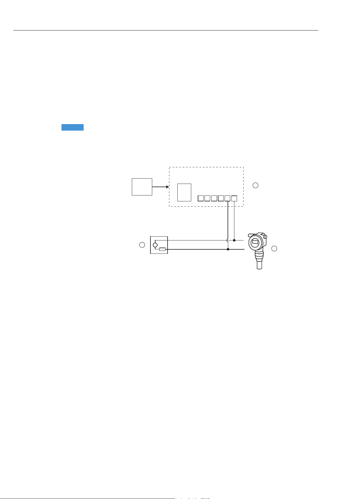
6.5.2 Field device in a closed-control loop with a communication resistor
The following functions are possible with this connection version:
• Digital HART communication if this is supported by the field device.
The WirelessHART adapter can be connected to an existing installation comprising a HART
field device and a power supply system that includes a communication resistor. Digital HART
communication is possible.
Note!
NOTE
• The terminals for listening to the communication can be defined or restricted in the Wake-
up Detection parameter (page 60). By restricting the terminal it is possible to prevent the
WirelessHART adapter from entering the configuration mode.
Connect the WirelessHART adapter as illustrated below:
24 –
230 V
AC / DC
3
connection of a field device in a closed-control loop with a communication resistor
1 WirelessHART adapter terminals
2 Field device
24 V
1 2 3 4
+
–
5
6
+
1
+
2
––
Fig. 6-6: WirelessHART adapter –
3 PLC, remote I/O or DC voltage power unit with a
communication resistor
36 Endress + Hauser
Page 37
WirelessHART adapter SWA70 Electrical installation of SWA70 with wide range power unit
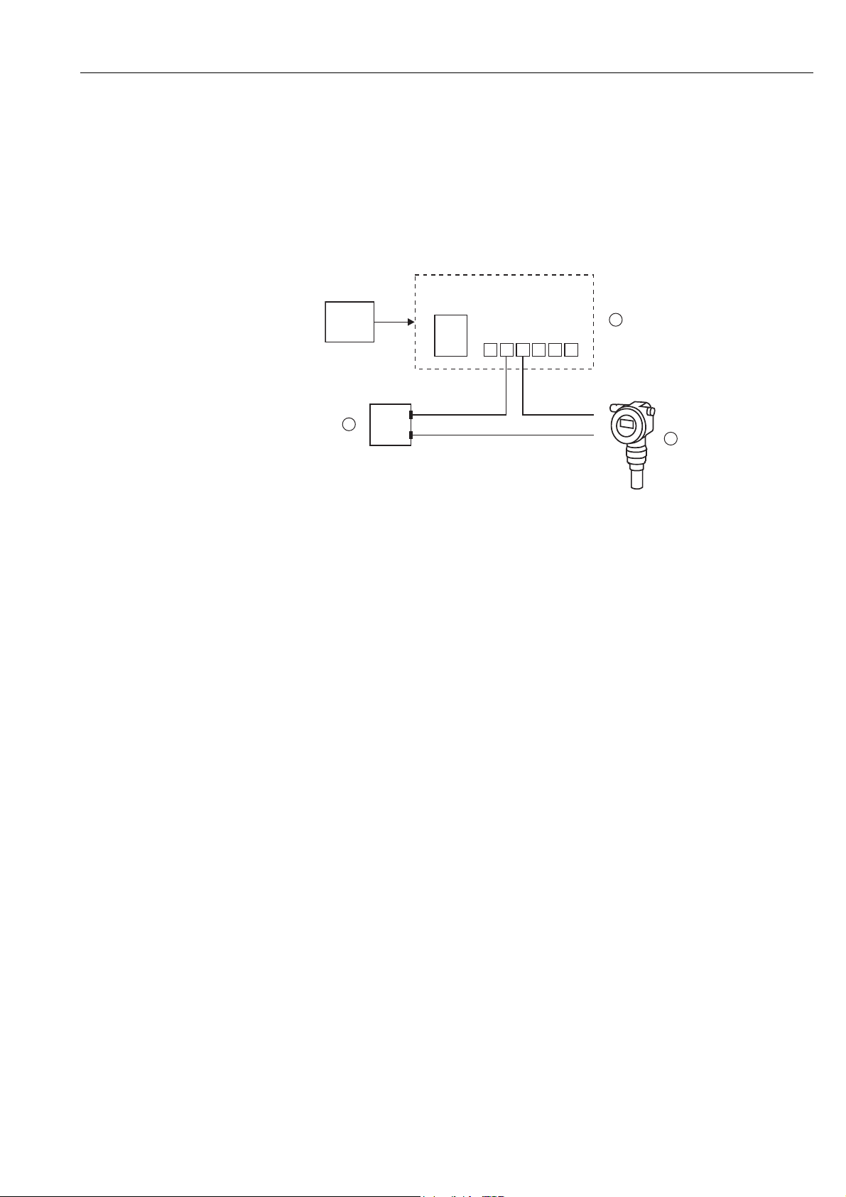
6.5.3 Field device in a closed-control loop without a communication resistor
The following functions are possible with this connection version:
• Current measurement in the 4 to 20 mA range
• Digital HART communication if this is supported by the field device.
Connect the WirelessHART adapter as illustrated below:
24 –
230 V
AC / DC
–
++
3
––
Fig. 6-7: WirelessHART adapter with wide range power unit –
connection of a field device in a closed-control loop without a communication resistor
1 WirelessHART adapter terminals
2 Field device
24 V
+
1 2 3 4
1
5
6
2
3 PLC, remote I/O or DC voltage power unit
without a communication resistor
Endress + Hauser 37
Page 38
Electrical installation of SWA70 with wide range power unit WirelessHART adapter SWA70
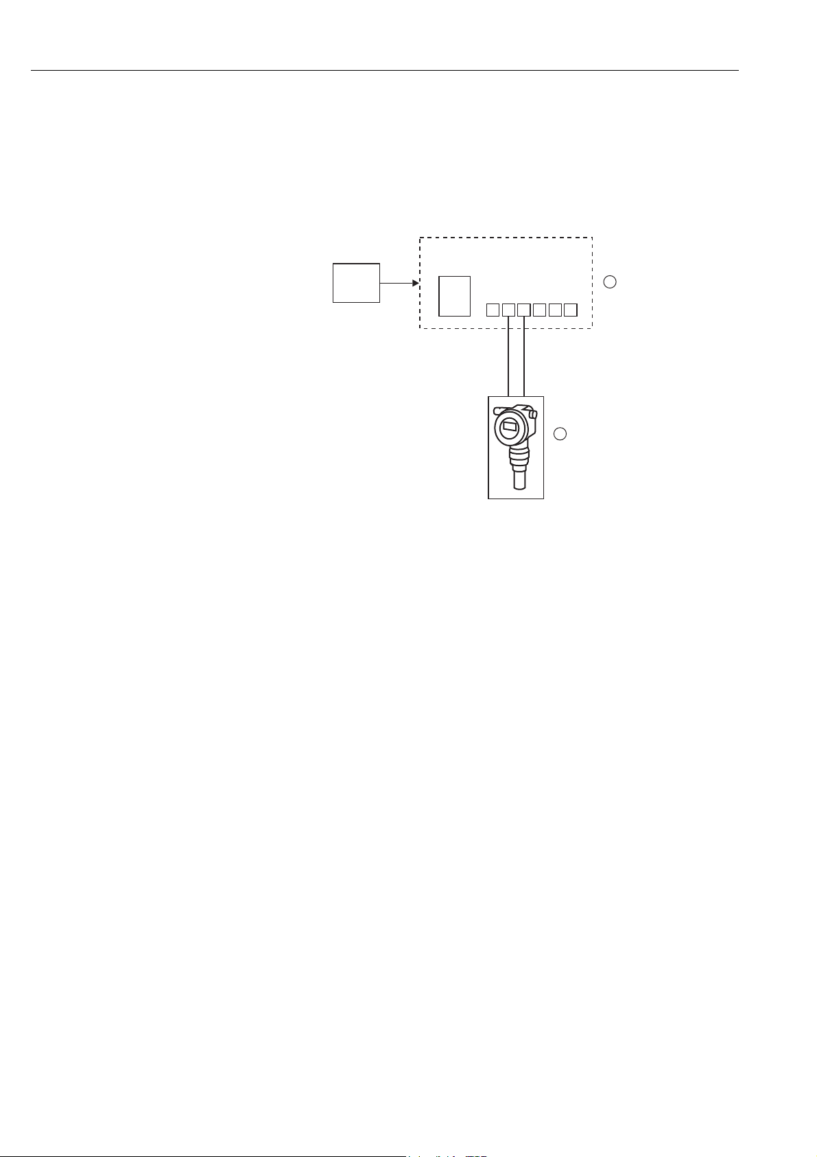
6.5.4 Four-wire field device
The following functions are possible with this connection version:
• Current measurement in the 4 to 20 mA range
• Digital HART communication if this is supported by the field device.
Connect the WirelessHART adapter as illustrated below:
24 –
230 V
AC / DC
24 V
–
+
1 2 3 4
+
5
–
2
1
6
Fig. 6-8: WirelessHART adapter with wide range power unit –
connection of a four-wire field device
1 WirelessHART adapter terminals 1 to 6 2 Four-wire field device
38 Endress + Hauser
Page 39

WirelessHART adapter SWA70 Electrical installation of SWA70 with wide range power unit
6.5.5 Field devices in multidrop
The following functions are possible with this connection version:
• Digital HART communication in multidrop mode
Note!
NOTE
• To make the installation easy, the wide range power unit can be removed from the housing
to connect it to the power supply.
If you want to operate field devices in the HART multidrop mode, connect the field devices
as illustrated below. You can connect up to 4 field devices.
24 –
230 V
AC / DC
1 WirelessHART adapter terminals 2 Field devices
24 V
–
2
Fig. 6-9: WirelessHART adapter with wide range power unit –
multidrop connection via internal power supply
+
+
1 2 3 4
–
5
+
1
6
–
+
–
+
–
6.6 Post-connection check
After wiring the WirelessHART adapter, perform the following final checks:
• Is the assignment of the terminals correct?
• Is the cable gland sealed tightly?
Endress + Hauser 39
Page 40
Electrical installation of SWA70 with DC power unit WirelessHART adapter SWA70
7 Electrical installation of SWA70
with DC power unit
For the technical data, such as the cable specification, see the Technical Information
document for "WirelessHART Adapter SWA70" (TI00026S).
7.1 Power supply via DC power unit
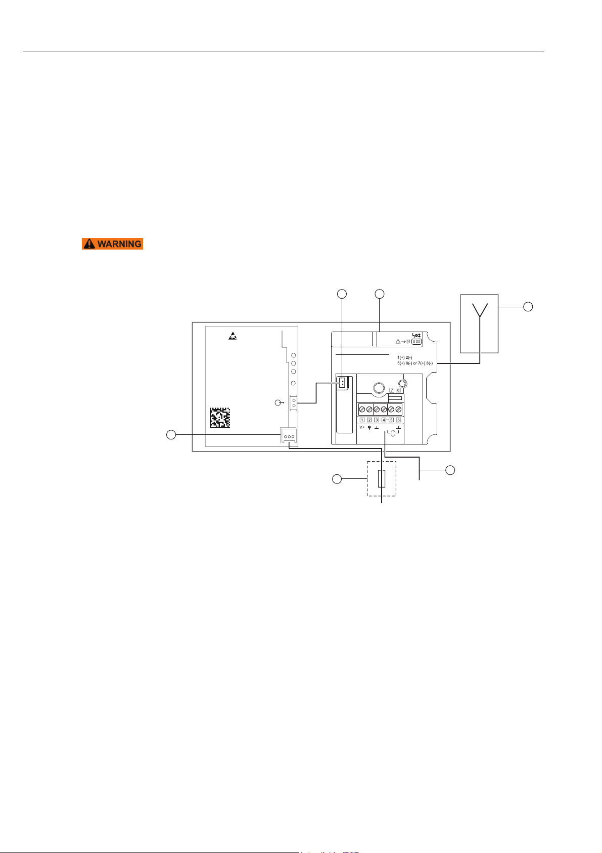
The WirelessHART adapter with the DC power unit is connected to the power supply via the
M12 connector. See “Connecting the M12 socket” on page 41.
Warning!
• The WirelessHART adapter must be protected at the customer's site by an external 1A
slow-blow backup fuse, designed for min. 250 V AC, and approved for the particular
application.
Power
Charge
Ready
LED on
DCPS
Solar module power supply
Serial number
abxxxx24yyy
Date: JJJJ-MM
Main board
supply
4
Fig. 7-1: Block circuit diagram of power supply via DC power unit
1 Antenna
2 Field device connection, see chapter "Wiring
diagrams for DC power unit" on page44.
5
Common types of connection:
2-wire device, adapter powered
HART modem/Handheld
Please see manual for more types
power
3
6
2
3 Suitable back-up fuse, provided by the customer
onsite
4 Connection for power supply of solar module
5 Internal DC power supply
6 WirelessHART adapter main PCB
1
40 Endress + Hauser
Page 41

WirelessHART adapter SWA70 Electrical installation of SWA70 with DC power unit
7.2 Connecting the M12 socket
A WirelessHART adapter with the DC power unit is connected to the power supply via the
M12 connector. An M12 socket is included in the delivery.
Disassembly and assembly
PIN assignment
of M12 socket
1
Fig. 7-2: Disassembling and assembling the M12 socket
1 Socket insert with terminals
2 Coupling sleeve
2
3 Seal
4 Coupling nut
343
1. Insert the seal into the narrower of the two openings of the coupling sleeve.
2. Guide the cable through the coupling nut and coupling sleeve.
3. Connect the cable in accordance with the PIN assignment. Tighten the screws in the
socket insert.
3
2
4
1
Fig. 7-3: PIN assignment of M12 socket
Power supply version PIN assignment
1234
DC power unit, 8-50 V DC n.c. n.c. – +
4. Screw together the socket insert and the coupling sleeve. For this purpose turn the
knurled head screw while holding the coupling sleeve steady.
5. Screw down the coupling nut.
Endress + Hauser 41
Page 42

Electrical installation of SWA70 with DC power unit WirelessHART adapter SWA70
7.3 Connecting the field device
You require the following tools for the electrical installation of the WirelessHART adapter:
• Torx T10 for the housing screws
• Flat-blade screwdriver with a blade width of 2.5 mm for the screws on the terminal block
• Wrench 25 mm across flats for the cable entry
7.3.1 Cable specification
Note!
NOTE
• When mounting the adapter directly on the field device, use the twin-core cable included
in the delivery. You can use a commercially available instrument cable for remote
mounting. If severe electromagnetic interference can be expected from machines or
wireless devices, for instance, we recommend the use of a shielded cable.
• Connect the shielding in accordance with local regulations. With regard to the shielding
connection, no special requirements must be met for the WirelessHART adapter .
7.3.2 Wiring
You can mount the WirelessHART adapter either directly on the field device or at a distance
from the field device on a wall or post using a bracket.See “Wall mounting” on page 18.
See “Pipe mounting” on page 20.
NOTE
As the secondary cable entry is always used for the power supply on WirelessHART adapters
with a DC power unit, the primary cable entry must always be used for wiring between the
WirelessHART adapter and the field device.
Note!
• For the primary cable entry make sure that the water does not flow along the cable and
enter the housing.
Proceed as follows to mount directly on the field device:
1. Open the housing of the WirelessHART adapter.
2. Guide the cable through the cable entry.
3. Wire the cable with the appropriate terminals of the WirelessHART adapter.
See “Wiring diagrams for DC power unit” on page 44.
4. Wire the field device as described in the operating manual for the field device in
question.
5. If the field device is not put into operation immediately after wiring, close the housing of
the WirelessHART adapter and the connection compartment of the field device. Tighten
the housing screws of the WirelessHART adapter with a torque of 0.6 Nm.
42 Endress + Hauser
Page 43
WirelessHART adapter SWA70 Electrical installation of SWA70 with DC power unit
7.4 SWA70 terminals
For the permitted connection data, see the Technical Information document for
"WirelessHART Adapter SWA70" (TI00026S).
Note!
NOTE
• On account of the internal communication resistor, the power supply of the field device
varies depending on the set current and terminal voltage.
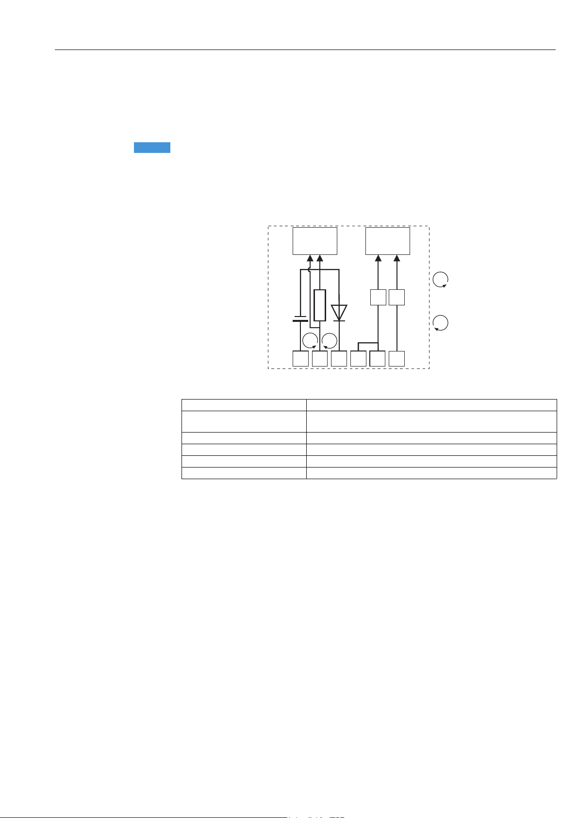
For connection purposes, the WirelessHART adapter contains a terminal block with screw
terminals 1-6 and the 2 terminals 7 and 8.
Loop current
measurement
and HART
communication
HART
communication
7
8
123 4
Fig. 7-4: Assignment of terminals
Terminals Description
1 and 2 • Field device power supply
• 4 to 20 mA/HART input
2 and 3 4 to 20 mA/HART input
4 or 5 High-impedance HART input/output terminals
3 or 6 High-impedance HART input/output terminals and ground
7 and 8 HART modem connection
5
6
Loop current
measurement
1 – 2
Loop current
measurement
2 – 3
Endress + Hauser 43
Page 44

Electrical installation of SWA70 with DC power unit WirelessHART adapter SWA70
7.5 Wiring diagrams for DC power unit
For the WirelessHART adapter with a DC power unit, the following options are available to
electrically connect a field device as a:
• Two-wire field device with power supplied by adapter: see page 44.
• Four-wire field device: see page 45.
• Field device in a closed-control loop with a communication resistor: see page 46.
• Field device in a closed-control loop without a communication resistor: see page 47.
Note!
NOTE
• To ensure smooth, unhindered operation, the solar module and field device must either be
powered by different sources or powered by the same source with two galvanically isolated
outputs.
7.5.1 Two-wire field device with power supplied by adapter
The following functions are possible with this connection version:
• Power supply to the field device
• Current measurement in the 4 to 20 mA range
• Digital HART communication if this is supported by the field device.
Connect the WirelessHART adapter as illustrated below:
8 –
25 V DC
1 2 3 4
+
Fig. 7-5: WirelessHART adapter with DC power unit –
connection of a two-wire field device with power supplied by the adapter
1 WirelessHART adapter terminals 2 Field device
5
–
2
1
6
44 Endress + Hauser
Page 45
WirelessHART adapter SWA70 Electrical installation of SWA70 with DC power unit
7.5.2 Four-wire field device
The following functions are possible with this connection version:
• Current measurement in the 4 to 20 mA range
• Digital HART communication if this is supported by the field device.
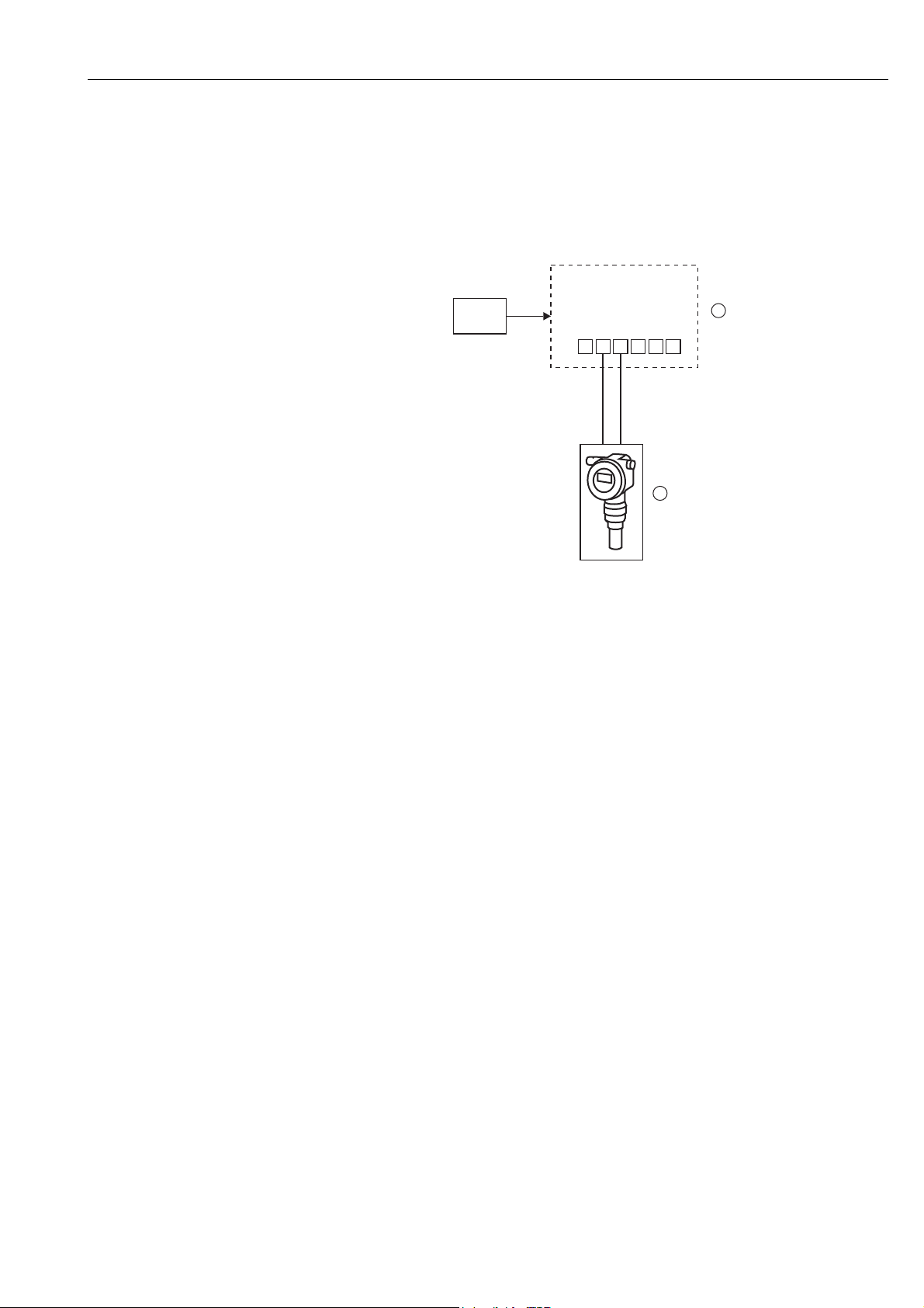
Connect the WirelessHART adapter as illustrated below:
8 –
25 V DC
1 2 3 4
+
Fig. 7-6: WirelessHART adapter with DC power unit –
connection of a four-wire field device
1 WirelessHART adapter terminals 2 Four-wire field device with galvanic isolation
5
–
2
1
6
Endress + Hauser 45
Page 46

Electrical installation of SWA70 with DC power unit WirelessHART adapter SWA70
7.5.3 Field device in a closed-control loop with a communication
resistor
The WirelessHART adapter can be connected to an existing installation comprising a HART
field device and a power supply system that includes a communication resistor.
The following functions are possible with this connection version:
• Digital HART communication if this is supported by the field device.
Connect the WirelessHART adapter as illustrated below:
8 –
25 V DC
3
Fig. 7-7: WirelessHART adapter with DC power unit –
connection of a field device in a closed-control loop with a communication resistor
1 WirelessHART adapter terminals
2 Field device
1
1 2 3 4
+
––
5
6
+
2
3 PLC, remote I/O or DC voltage power unit with a
communication resistor
46 Endress + Hauser
Page 47
WirelessHART adapter SWA70 Electrical installation of SWA70 with DC power unit
7.5.4 Field device in a closed-control loop without a communication resistor
The following functions are possible with this connection version:
• Current measurement in the 4 to 20 mA range
• Digital HART communication if this is supported by the field device.
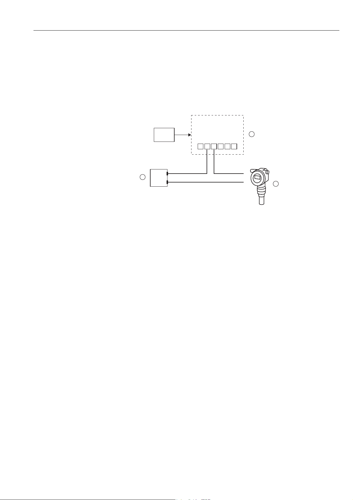
Connect the WirelessHART adapter as illustrated below:
8 –
25 V DC
1 2 3 4
5
1
6
++
3
––
Fig. 7-8: WirelessHART adapter with DC power unit –
connection of a field device in a closed-control loop without a communication resistor
1 WirelessHART adapter terminals
2 Field devices
3 PLC, remote I/O or DC voltage power unit without
a communication resistor
2
7.6 Post-connection check
After wiring the WirelessHART adapter, perform the following final checks:
• Is the assignment of the terminals correct?
• Is the cable gland sealed tightly?
Endress + Hauser 47
Page 48
Operation WirelessHART adapter SWA70
8 Operation
8.1 Display and operating elements – main PCB
Warning!
• The housing of the WirelessHART adapter may not be opened in hazardous areas if dust
is present. The housing may only be opened in a dusty atmosphere if adequate ventilation
ensures the environment is free of dust. See “Operational safety” on page 7.
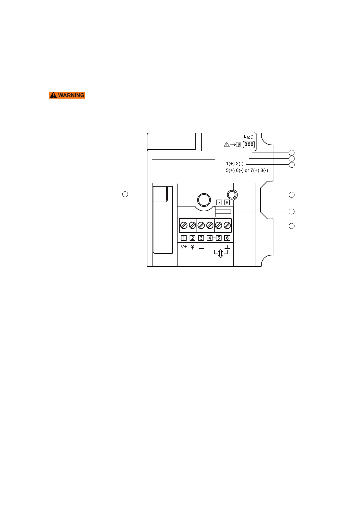
The following display and operating elements are visible inside the WirelessHART adapter:
Common types of connection:
2-wire device, adapter powered
HART modem/Handheld
Please see manual for more types
7
power
Fig. 8-1: Display and operating elements on the PCB cover
1 Yellow light emitting diode: communication status
2 Green light emitting diode: battery status
3 Red light emitting diode: active communication,
error messages
4 Push button
1
2
3
4
5
6
5 Terminals for HART modem
6 Terminals 1 to 6
7 Socket for connector of the electronically controlled
power supply unit or the battery unit
48 Endress + Hauser
Page 49
WirelessHART adapter SWA70 Operation
8.1.1 Push button
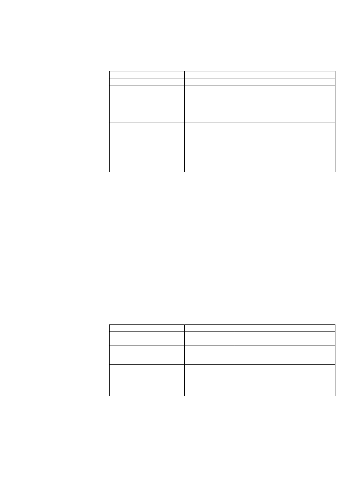
Pressing the push button executes a range of functions depending on how long the button is
actually pressed. A power supply unit must be connected.
When operating with
connected power supply
unit
Time pressed Function
0.2 s No function
> 0.2 to 5 s LEDs light up to indicate the status of the adapter (see chap. 8.1.2)
– When the adapter attempts to join the network, the LEDs continue to
indicate the status until the connection has been made.
5 to 10 s Joins the adapter to the wireless network
– Once the button has been pressed for 5 seconds, the yellow light
emitting diode flashes at 3 Hz
10 to 15 s Activates the mode for configuring the connected field device
– Once the button has been pressed for 10 seconds, the red light emitting
diode flashes at 3 Hz
– If HART communication does not take place in the configurable time
frame (e.g. 300 seconds), or if the push button is pressed again for 10 to
15 s, the user quits the mode for configuring the connected field device.
The red light emitting diode goes out.
> 15 s No function
Resetting the
configuration to the
default settings
Resetting the
configuration and
firmware to the default
settings
Yellow light emitting
diode:
communication status
Prerequisite: The power supply unit must be disconnected.
1. Press the push button.
2. Press and hold the push button and reconnect the power supply unit. The red LED is lit.
3. Press and hold the push button for 10 to 15 seconds. The red LED flashes at 2.5 Hz. The
configuration is reset to the manufacturer's default settings.
Prerequisite: The power supply unit must be disconnected.
1. Press the push button.
2. Press and hold the push button and reconnect the power supply unit. The red LED is lit/
flashes at 2.5 Hz/is lit.
3. Press and hold the push button for 20 to 25 seconds. The red LED flashes at 1.25 Hz.
The firmware and configuration are reset to the factory settings.
8.1.2 Display
If the push button is pressed briefly, the three light emitting diodes indicate the current
status.
Yellow light emitting diode Communication status Meaning
Lit Connected, alternative
Flashes at 1 Hz Connected, no
Flashes at 3 Hz Joining Currently attempting to join the network,
Off Not connected The device has not joined the network
1) Alternative communication path: information is sent by a neighboring adapter.
1)
path
alternative path
Adapter is connected to the network
– An alternative communication path exists
Adapter is connected to the network
1)
– An alternative communication path does not
exist
e.g. for 40 min once the battery unit is connected
– The length of the joining period can be
configured.
Endress + Hauser 49
Page 50
Operation WirelessHART adapter SWA70
Green light emitting
diode: battery status
Red light emitting diode:
active communication,
error message
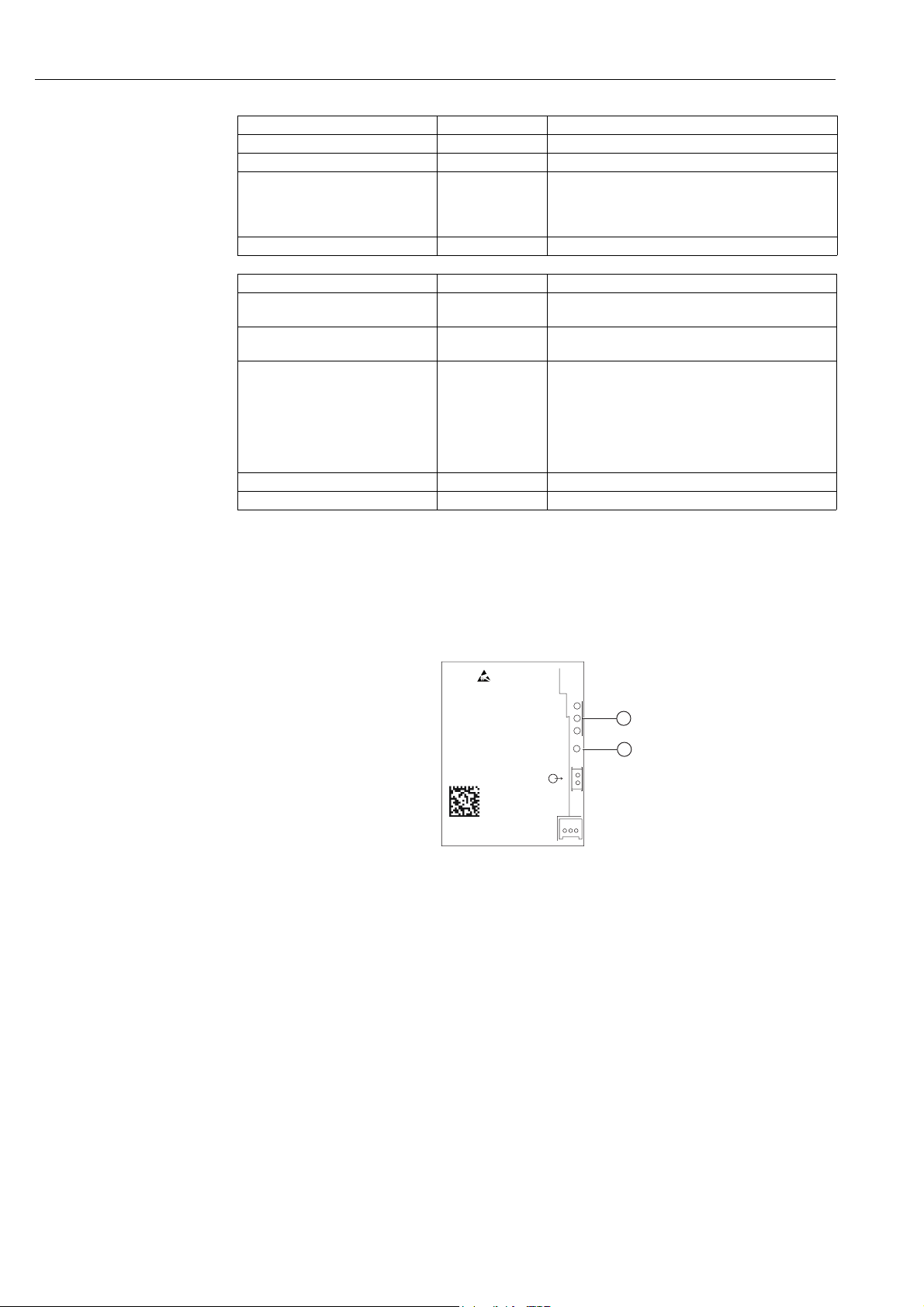
Green LED Battery status Meaning
Lit Normal The battery unit will last for at least one more month
Flashes at 1 Hz Warning The battery unit will last for less than one month
Flashes at 3 Hz Alarm Measurement at the field device has been stopped
– A connection is not guaranteed
– The WirelessHART adapter can still be operated but
it is no longer possible to power the field device
Off Empty battery Battery unit is empty or not connected
Red light emitting diode Status Meaning
Flashes: 50 ms on, 950 ms off Communication
mode active
It is possible to communicate with the WirelessHART
adapter
Lit Internal fault Fault caused by the device.
– It cannot be corrected by the user.
Flashes at 1 Hz External fault It might be possible for the user to correct the fault.
– External faults can be viewed in the diagnostics
function of the DTM or DD
– Examples:
a) Temperature is outside the specified range
b) Measured value is outside the configured range
e.g. 4 to 20 mA
Flashes at 3 Hz Short-circuit Short-circuit at terminals 1 and 2
Off No fault
8.2 Operating and display elements – electronically controlled power supply units
One push button and three light emitting diodes can be found on the electronically
controlled power supply unit.
Power
Serial number
abxxxx24yyy
Date: JJJJ-MM
Uo ≤ DC V
Io ≤ mA
Po ≤ mW
Charge
Ready
LED on
1
2
Fig. 8-2: Operating and display elements, electronically controlled power supply units
1 Light emitting diodes 2 Push button
8.2.1 Push button
When you press the push button, the appropriate LEDs light up depending on the output
voltage currently present.
50 Endress + Hauser
Page 51
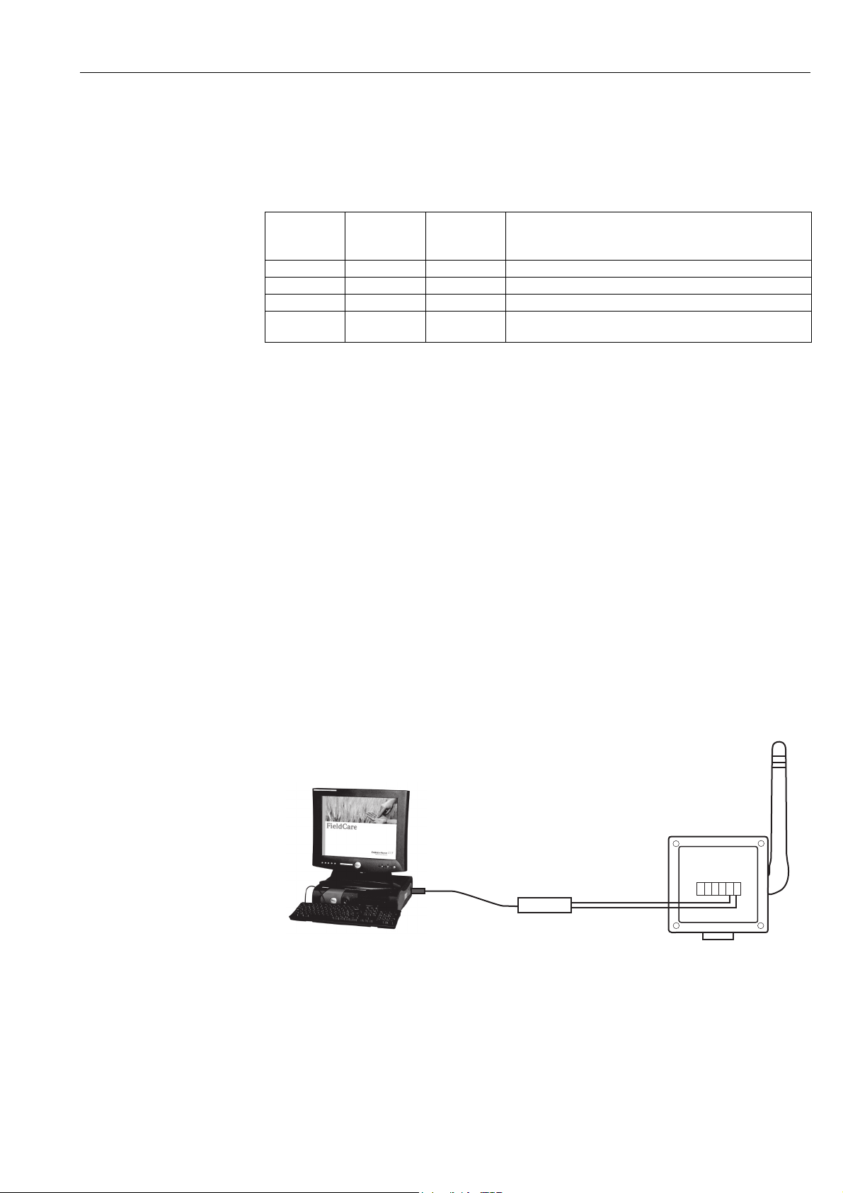
WirelessHART adapter SWA70 Operation
8.2.2 Light emitting diodes
The light emitting diodes indicate the level of power that is available for the field device, for
instance. The level of the power supply changes after the power supply has been switched
on or returns.
LED 1
(green)
Ready Charge Power
ON OFF ON Normal operating mode
OFF OFF OFF No external power supply.
ON ON OFF Buffer has been partially charged.
ON ON ON 70% of the buffer has been charged. LED 2 switches off as
LED 2
(yellow)
LED 3
(green)
Meaning
soon as the buffer is fully charged (100 %).
8.3 Operating the field device
Operate your field devices as specified in the operating manual for the devices in question.
8.4 Local configuration and remote configuration
The WirelessHART adapter is configured externally. There are various ways of doing this:
• Local configuration with FieldCare or DeviceCare via modem and DTM for SWA70
• Local operation with FieldXpert also in the hazardous area
• Remote configuration with FieldCare via WirelessHART Fieldgate SWG70 and DTM for
SWA70 and SWG70
• Remote configuration with a software and a gateway based on the device description
(DTM or DD)
For more information see chapter "Configuration and online parameterization" on page55.
When commissioning for the first time, the WirelessHART adapter must be configured via
a point-to-point connection using a HART modem, e.g. with FieldCare and a HART modem.
Connect the HART modem to terminals 5 and 6 or to terminals 7 and 8 of the WirelessHART
adapter.
Computer with FieldCare,
FieldXpert or DeviceCare
Serial port
e.g. USB or RS-232
HART modem
Fig. 8-3: Connecting a WirelessHART adapter to a computer via a modem
WirelessHART
adapter
Term inals
7 and 8
Endress + Hauser 51
Page 52

Commissioning WirelessHART adapter SWA70
9 Commissioning
9.1 Connected HART field devices
We recommend you commission the connected HART field device before commissioning the
WirelessHART adapter. In addition to configuring the field device, the following parameters
must also be configured:
• HART address = 1
The field device is set to the multidrop mode and the current signal is frozen at 4 mA for
the "two-wire field device with power supplied by the WirelessHART adapter"
configuration.
If more than one field device is connected to the WirelessHART adapter, each field device
must be assigned its own individual address between 1 and 14, such as 1, 2, 3, 4 for
instance. Up to four connected field devices are allowed to operate in the multidrop mode
with an external power supply.
• Device Tag: This is used to identify the measuring point.
• Long Tag: This is used to identify the field device in the network.
The Long Tag parameter is available with HART Version 6.0 and higher. In older versions,
the Message parameter is used for this purpose.
Start commissioning as indicated below for the "two-wire field device with power supplied by
the WirelessHART adapter" configuration. You can perform commissioning via the display,
Field Xpert or FieldCare.
NOTE
1. Keep pressing the push button on the WirelessHART adapter until the red light emitting
diode flashes.
2. Power is supplied to the field device for 5 minutes. You can specify the length of time in
the Configuration Time parameter in the SWA70 DTM.
See “Field device power” on page 74.
Note!
• You may not change the address if the field device is connected in a circuit with a PLC or a
remote I/O. This address is 0 in most instances.
• It is not necessary to assign different HART addresses to different WirelessHART adapters.
The address that is used in the wireless network contains the serial number of the
WirelessHART adapter and is therefore unique.
• 4 to 20 mA field devices do not require preconfiguration. Scaling and linearization are
configured in the SWA70 DTM.
52 Endress + Hauser
Page 53
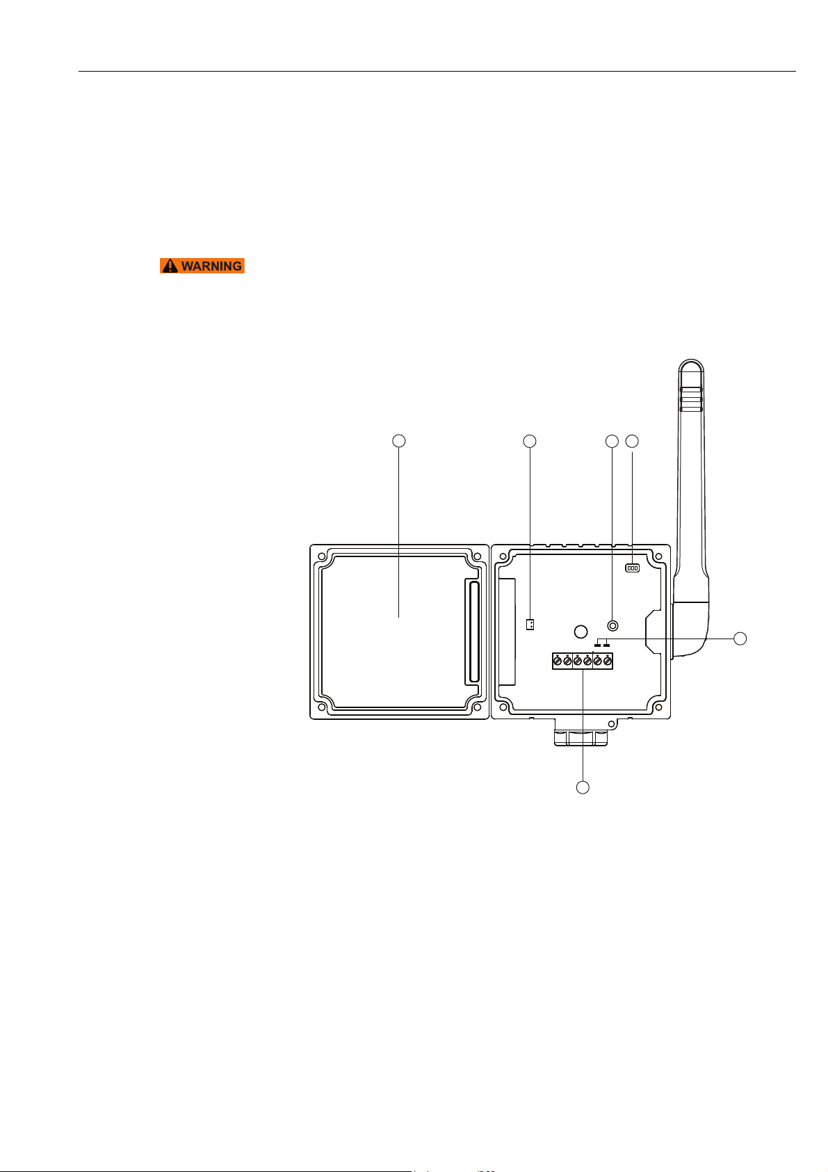
WirelessHART adapter SWA70 Commissioning
9.2 Inserting and connecting the battery unit
You must first open the housing to insert the battery unit. Please pay attention to the
operational safety instructions. See “Operational safety” on page 7.
The battery unit only needs to be inserted for the "WirelessHART adapter with battery unit"
device version. The other versions are fully assembled when delivered.
Warning!
• The housing of the WirelessHART adapter may not be opened in hazardous areas if dust
is present. The housing may only be opened in a dusty atmosphere if adequate ventilation
ensures the environment is free of dust.
You require a Torx T10 to open the housing.
4
Fig. 9-1: Battery compartment with housing open
3
5
1
2
6
1 Light emitting diodes
2 Push button
3 Socket for battery connector
4 Battery compartment
5 Terminals 1 to 6
6 Terminals for HART modem
Proceed as follows to connect the battery unit:
1. Insert the battery unit into the battery compartment, making sure that the battery unit
engages with a click.
2. Insert the battery connector into the socket on the PCB cover.
Once voltage is supplied to the WirelessHART adapter, the adapter's operating software
starts up. A WirelessHART adapter self-test is performed to check whether the assignment
of the terminals has been modified. If the device is being commissioned for the first time, the
assignment of the terminals is determined.
Endress + Hauser 53
Page 54

Commissioning WirelessHART adapter SWA70
9.3 Checks during commissioning
When commissioning the WirelessHART adapter, perform the following checks:
• Has the battery unit or the electronically controlled power supply unit been inserted
correctly?
• Is the connecting cable plugged in correctly?
• Is the device ready for operation and do the light emitting diodes light up when the push
button is pressed briefly?
If the field device is not put into operation immediately after commissioning, close the
housing of the WirelessHART adapter and the connection compartment of the field device.
Tighten the housing screws of the WirelessHART adapter with a torque of 0.6 Nm.
54 Endress + Hauser
Page 55
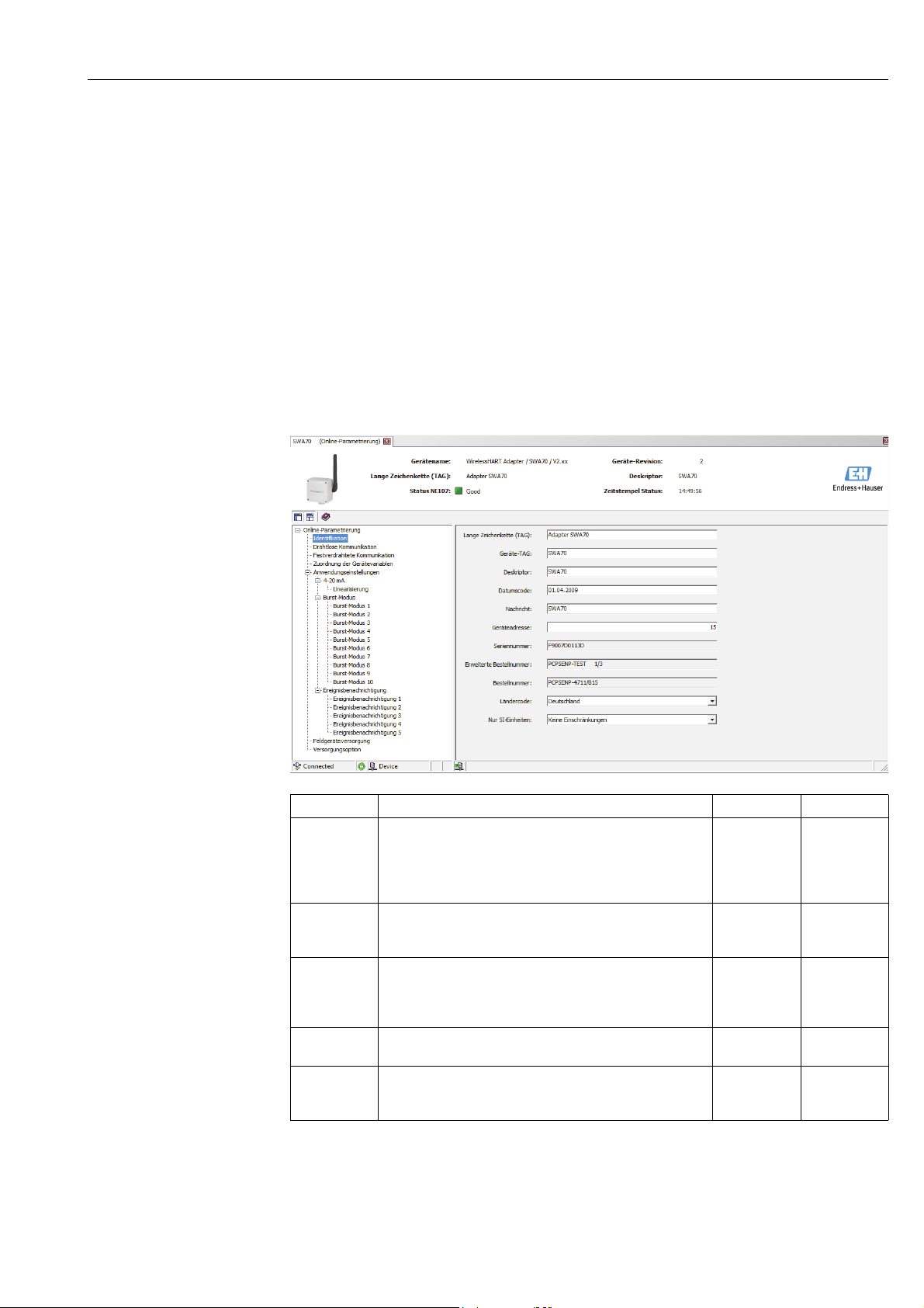
WirelessHART adapter SWA70 Configuration and online parameterization
10 Configuration and online parameterization
The configuration and parameterization are described using the example of
Endress+Hauser's "FieldCare" asset management tool.
10.1 Identification
The parameters that are required to identify the WirelessHART adapter can be configured
in the SWA70 DTM. The default settings appear in the individual input boxes.
1. Click Identification in the DTM navigation tree.
– You can enter text in the white fields. Press Enter to save your changes.
– The gray fields are read-only.
– An explanation of the individual parameters is provided in the "Identification
parameters" table below. Mandatory fields are highlighted in bold.
Identification parameters
Parameter Meaning Example Default
Long Tag For devices with HART version 6.0 and higher: unique
identification of the WirelessHART adapter in the network
and the plant. The parameter is used to configure the burst
mode and event notification.
– Max. 32 characters, ISO-Latin-1 string
Device Tag For reasons of compatibility, we recommend entering similar
information for the Device Tag and the Long Tag.
– Max. 8 characters, Packed-ASCII string*
Descriptor String comprising a maximum of 16 characters which the user
can use to describe the function or the location of the
WirelessHART adapter, for example.
– Packed-ASCII string with maximum 16 characters*
Date Code Date in dd.mm.yyyy format
– The date of the last change can be entered, for example
Message Max. 32-character message that can be used randomly as
required.
– Max. 16 characters, Packed-ASCII string*
WA001
WA001
Area 2 Tank 3
10.03.2009 01.04.2009
Endress + Hauser 55
Page 56

Configuration and online parameterization WirelessHART adapter SWA70
Parameter Meaning Example Default
Device
address
Serial number Serial number of the WirelessHART adapter
Ext. Order Code Extended order number
Order number Compact notation of the WirelessHART adapter order code
Country Code Code for the country in which the WirelessHART adapter is
SI Units Only Set of options for all the unit parameters of the WirelessHART
*Valid character set: @ A B C D E F G H I J K L M N O P Q R S T U V W X Y Z [ \ ] ^ _ SP ! " # $ % & ' ( ) * + , - . / 0 1
2 3 4 5 6 7 8 9 : ; < = > ?
HART address of the WirelessHART adapter on the wired
interface
– Range: 0-63
The "Long Tag" and the "MAC Address" are used to identify the
WirelessHART adapter in the wireless network. Therefore, it is
not necessary to assign different "polling addresses" to
different WirelessHART adapters.
operated.
– Controls the signal strength; if the WirelessHART adapter is
not already connected to a network, the signal strength is
set to 0 dBm in accordance with national restrictions.
– Controls the setting of the SI unit: The "SI Units Only"
parameter is set in accordance with national restrictions.
adapter
– Unit codes limited to the SI Units only: only SI units are
displayed.
– No restrictions: metric and US units are displayed.
15 15
United States Germany
Unit codes
limited to the
SI Units only.
No restrictions
56 Endress + Hauser
Page 57
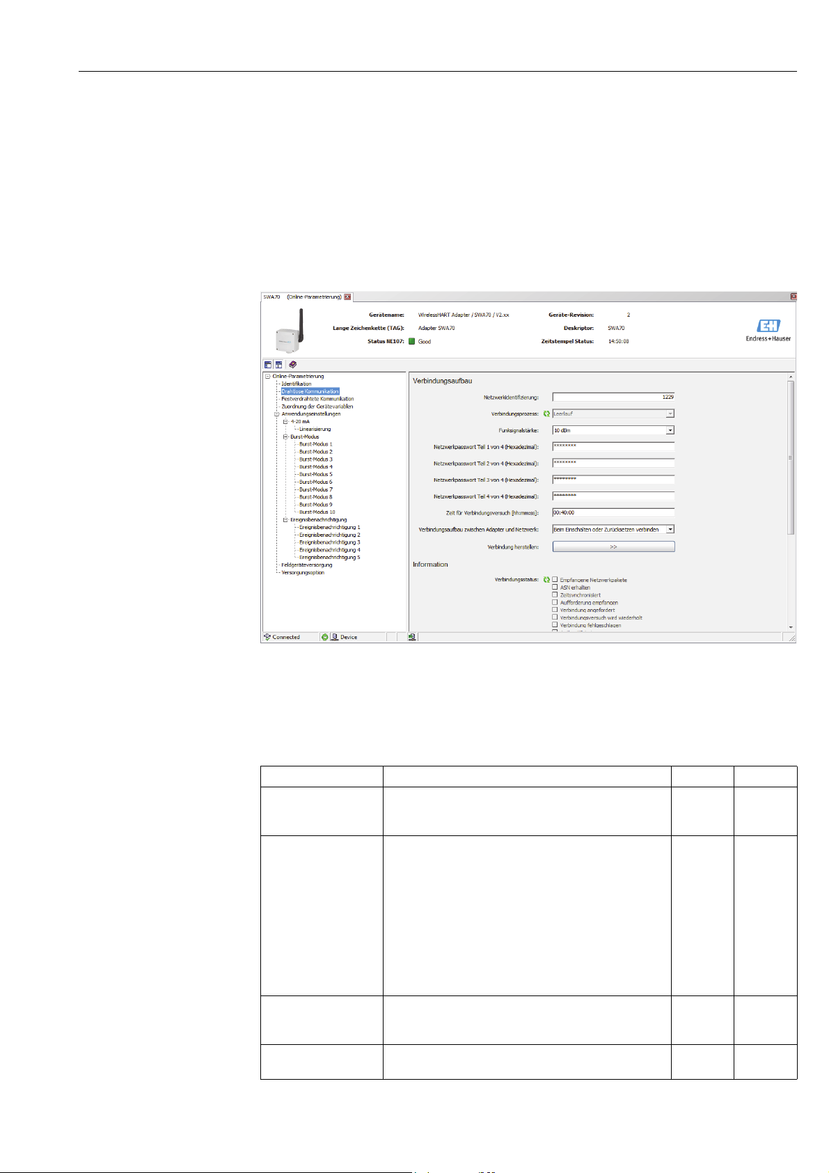
WirelessHART adapter SWA70 Configuration and online parameterization
10.2 Wireless communication
The parameters that are required to integrate the WirelessHART adapter into a wireless
network can be configured in the SWA70 DTM.
1. Click Wireless Communication in the DTM navigation tree.
– You can enter text in the white fields. Press Enter to save your changes.
– The gray fields are read-only.
– An explanation of the individual parameters is provided in the "Wireless
communication parameters" table below. Mandatory fields are highlighted in bold.
Wireless communication
parameters
2. Configure the parameters Network Identification, Radio Power, Join Key Part 1 of 4
to Join Key Part 4 of 4, Join Shed Time, Join Mode.
3. Press the Execute Join button to download the network settings and save them in the
WirelessHART adapter.
– The joining status can be tracked in the Join Status parameter.
Parameter Meaning Example Default
Network Identification Identification number of the network the WirelessHART
adapter is joining
– Range: 0 to 65535
Wireless Operation
Mode
Radio Power RF power level
Join Key
Part 1 of 4
Indicates the operation mode of the WirelessHART adapter
• Idle: waiting
• Active Search: searching for neighbors
• Negotiating: connection parameters are being exchanged
with the network manager
• Quarantined: network manager has denied connection.
Adapter temporarily excluded from the network
• Operational: adapter is connected
• Suspended: permanently excluded from the network
• Deep sleep/Ultra-Low Power/Passive Search: adapter is
inactive
– 0 or 10 dBm
– National restriction to 0 dBm is possible (e.g. in Japan)
Network password, 8 character hexadecimal, Part 1 of 4 33333333 456E6472
43 1447
10 dBm 10 dBm
Endress + Hauser 57
Page 58
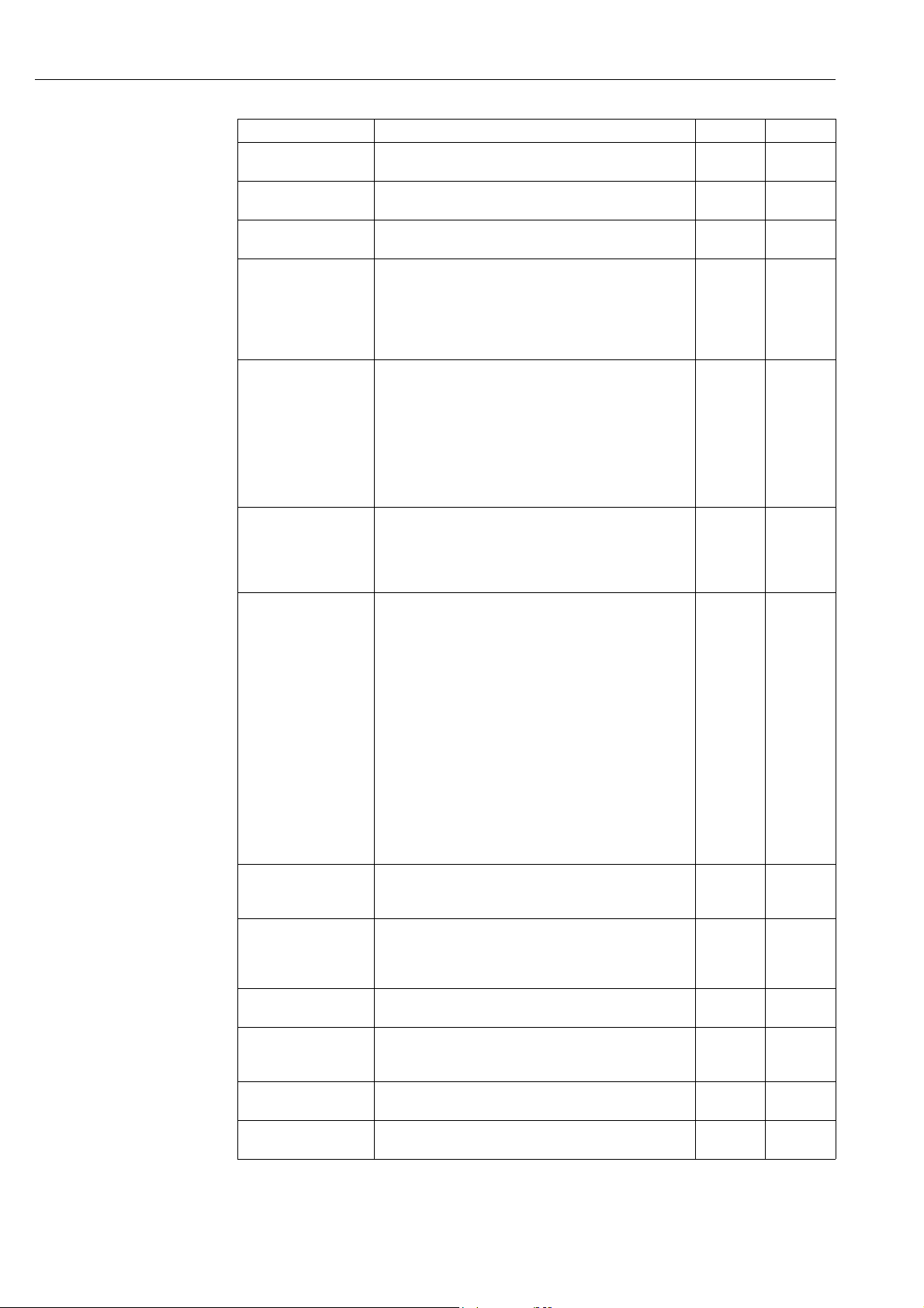
Configuration and online parameterization WirelessHART adapter SWA70
Parameter Meaning Example Default
Join Key
Part 2 of 4
Join Key
Part 3 of 4
Join Key
Part 4 of 4
Join Shed Time
[hh.mm.ss]
Join Mode Way in which the WirelessHART adapter joins the network:
Execute Join Pressing this button writes the parameters configured
Join Status Provides information about the current status when the
Total Number of
Neighbors
Number of Advertising
Packets Received
Number of Join
Attempts
Active Advertising Shed
Time [hh.mm.ss]
Request Active
Advertising
Number of Neighbors
Advertising
Network password, 8 character hexadecimal, Part 2 of 4 33333333 65737320
Network password, 8 character hexadecimal, Part 3 of 4 33333333 2B204861
Network password, 8 character hexadecimal, Part 4 of 4 33333333 75736572
Time in hh.mm.ss that the adapter is given to attempt to
join the network after the "Join Key" and "Network
Identification" information has been entered correctly.
– When this time elapses, the WirelessHART adapter
continues its attempt to join the network but with less
intensity.
• Do not attempt to join: do not join the network. The
parameters are saved.
• Join now: join the network now. Once the WirelessHART
adapter has successfully joined the network, it
automatically switches to "Attempt to join immediately
on power-up or reset".
• Attempt to join immediately on power-up or reset: join as
soon as the device is restarted.
above to the WirelessHART adapter. These parameters are
then used.
– If the "Join Mode" parameter is set to "Join now", the
WirelessHART adapter attempts to join the network.
adapter is attempting to join the network.
• Network Packets Heard: network packets received.
• ASN Acquired: "Absolute Slot Number (ASN)" has been
received.
• Synchronized to Slot Time: synchronized with the
network.
• Advertisement Heard: received advertising packets to
send data.
• Join Requested: requested to join network.
• Join Retrying: retry joining the network.
• Join Failed: attempt to join network has failed.
• Authenticated: authenticated
• Network Joined: adapter has joined the network
• Negotiating Network Properties: exchanging network
parameters
• Normal Operation Commencing: fully connected
Indicates the number of WirelessHART devices in the
vicinity of the adapter to which a connection has been
made.
When the adapter joins the network, indicates the number
of advertising packets which were sent by the neighboring
devices and/or network managers and received by the
WirelessHART adapter.
Indicates the number of attempts the WirelessHART
adapter made to join the network
Time in hh.mm.ss during which the WirelessHART adapter
attempts to allow other adapters to join the network more
quickly.
Pressing this button activates the "Active Advertising Shed
Time" in the WirelessHART adapter.
Indicates the number of neighbors that transmit advertising
packets to send data.
00:40:00 00:40:00
Join now Attempt to
join
immediatel
y on powerup or reset
00:40:00 00:00:00
58 Endress + Hauser
Page 59
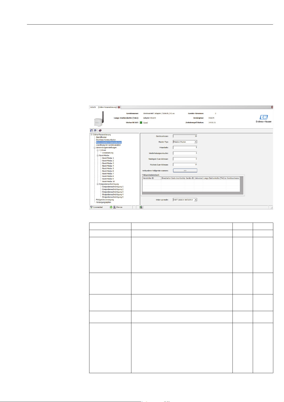
WirelessHART adapter SWA70 Configuration and online parameterization
10.3 Wired communication
The parameters that are required to set up wired HART communication between the
WirelessHART adapter and one or more HART field devices can be configured in the
SWA70 DTM.
1. Click Wired Communication in the DTM navigation tree.
– You can enter text in the white fields. Press Enter to save your changes.
– The gray fields are read-only.
– An explanation of the individual parameters is provided in the "Wired communication
parameters" table below. Mandatory fields are highlighted in bold.
Wired communication
parameters
Parameter Meaning Example Default
Device address HART address of the WirelessHART adapter 63
Master Type In a current loop, different HART master types must be
assigned, for instance, to a device configurator - such as the
Field Xpert - and the WirelessHART adapter.
– Primary Master is the default setting.
– There is a Primary Master and a Secondary Master
– If a device configurator or another master/host is
connected, it must be set to the Secondary Master.
Preambles Number of preambles sent at start of the HART frame to
synchronize wired communication.
– Range: 5 to 20
– All connected devices require this setting
Retries Number of times the WirelessHART adapter tries to establish
communication with the connected field device before it
reports a communication error.
Lowest
Scan Address
Highest Scan Address Address up to which the WirelessHART adapter scans for
Address as of which the WirelessHART adapter starts
scanning for connected field devices.
connected field devices.
– A HART device providing a 4 to 20 mA output in a control
loop will have the address 0.
– Normally a single HART field device that is powered by the
WirelessHART adapter will have the address 1. This
ensures it works in multidrop mode. The current signal of
each user is frozen at 4 mA.
– Enter the highest address if several field devices (max. 4)
are connected in the multidrop mode.
Primary
Master
55
33
00
11
Primary
Master
Endress + Hauser 59
Page 60

Configuration and online parameterization WirelessHART adapter SWA70
Parameter Meaning Example Default
Scan Subdevices Pressing this button starts the search for connected field
devices.
– The field devices found are displayed in the SWA70 DTM.
– If the terminal assignment of the WirelessHART adapter
changes during operation, scanning must be performed
again.
– Please note that scanning is performed as soon as power is
supplied to the WirelessHART adapter. The table is then
populated automatically.
Field Device Database List of the field devices that are connected and recognized.
Wake-up Detection Specify the terminals that listen to the communication. By
restricting the terminal it is possible to prevent unnecessary
execution of the configuration mode and save energy.
– Terminals 1 to 4
– Terminals 5 to 8
– Terminals 1 to 8
This parameter is only relevant for the "Field device in a
closed-control loop" version.
60 Endress + Hauser
Page 61
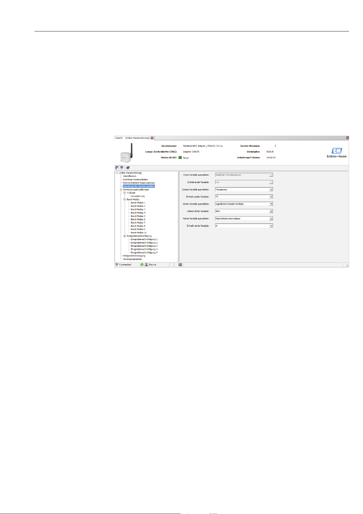
WirelessHART adapter SWA70 Configuration and online parameterization
10.4 Device variable mapping
The WirelessHART adapter can output the value and the status of different variables.
Four variables can be shown in the network. They can be displayed and configured in the
SWA70 DTM.
1. Click Device Variable Mapping in the DTM navigation tree.
– You can enter text in the white fields. Press Enter to save your changes.
– The gray fields are read-only.
– An explanation of the individual parameters is provided in the "Device variable
mapping parameters" table below. Mandatory fields are highlighted in bold.
2. The primary variable is permanently linked to the scaled loop current. The scaling and
unit can be changed in the DTM navigation tree in the Application Settings/4-20 mA
menu.
The following variables can be selected as the secondary, tertiary and quaternary
variable:
– Battery Voltage: current battery voltage
– Battery Voltage With Load: battery voltage with a load
– Battery Voltage Without Load During Battery Test
– Consumed Energy: energy drawn from the battery
– Estimated Lifetime: estimated lifetime in days
– Normalized Consumed Energy: energy consumed under normalized conditions
– RSL of Best Neighbor: signal strength of the "best" neighbor
– RSL of Second Best Neighbor: signal strength of the "second-best" neighbor
– Temperature: current temperature
– Temperature Min: minimum temperature that has been measured by the
WirelessHART adapter. The value can be reset.
– Temperature Max: maximum temperature that has been measured by the
WirelessHART adapter. The value can be reset.
The choice of unit matches the set variable.
Endress + Hauser 61
Page 62

Configuration and online parameterization WirelessHART adapter SWA70
Device variable mapping
parameters
Parameter Meaning Example Default
Select Primary Variable Primary variable
– The primary variable is permanently linked
to the loop current.
Primary Variable Unit Unit of the primary variable mbar mA
Select Secondary
Variable
Secondary Variable Unit Unit of the secondary variable °C °C
Select Tertiary Variable Tertiary variable RSL of Best
Tertiary Variable Unit Unit of the tertiary variable dB dB
Select Quaternary
Variable
Quaternary Variable
Unit
Secondary variable Temperature Temperature
Quaternary variable Estimated
Unit of the quaternary variable d d
Scaled Loop
Current
Neighbor
Lifetime
Scaled Loop
Current
RSL of Best
Neighbor
Estimated
Lifetime
10.5 4-20 mA (application setting)
When a HART device is connected to the WirelessHART adapter, all the parameters are read
via the digital signal. However, it is also possible to connect a 4–20 mA device to the
WirelessHART adapter. The WirelessHART adapter then measures the loop current and can
transmit it digitally. It is possible to adjust the 4 to 20 signal in the SWA70 DTM and perform
linearization if necessary. In addition, you can enter limit values that specify the proportional
value range and the alarm signals. If the values entered are exceeded or undershot, the
WirelessHART adapter issues a warning or an alarm, and an event notification where
warranted. See “Event notification (application setting)” on page 69.
1. Click Application Settings/4-20 mA in the DTM navigation tree to display the
appropriate parameters.
– You can enter text in the white fields. Press Enter to save your changes.
– The gray fields are read-only.
– An explanation of the individual parameters is provided in the "4-20 mA parameters"
table below. Mandatory fields are highlighted in bold.
62 Endress + Hauser
Page 63
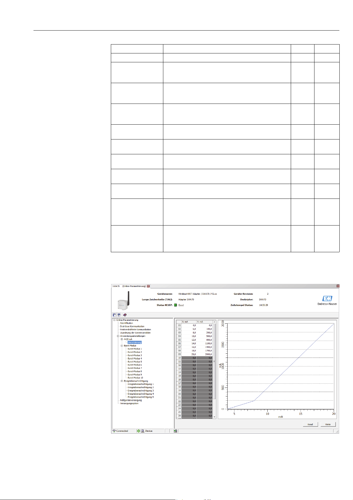
WirelessHART adapter SWA70 Configuration and online parameterization
4-20 mA parameters
Parameter Meaning Example Default
Primary Variable Unit The unit of the primary variable °C mA
Linearization Mode Determines how the value of the input current is converted
• Linear: proportional scaling over the set range
• Special Curve: scaling according to the "Linearization" table
Primary Variable
Upper Range Value
(20 mA)
Primary Variable
Lower Range Value
(4 mA)
Input Damping Damping factor of the input current (0-255 s)
Upper Fault-Current
Value
Upper Limit of
Proportional Range
Lower Limit of
Proportional Range
Lower Fault-Current
Value
Trim Loop Current Zero Pressing the button calls up a method for adjusting the
Trim Loop Current Gain Pressing the button calls up a method for adjusting the
Upper range value of the input current which corresponds to
the 20 mA value
Lower range value of the input current which corresponds to
the 4 mA value
– Damping is disabled if the setting is 0 s.
A fault is reported if this value is exceeded. 22 mA 22 mA
A warning is issued if this value is exceeded. 20.5 mA 20.5 mA
A warning is issued if this value is undershot. 3.8 mA 3.8 mA
A fault is reported if this value is undershot 3.6 mA 3.6 mA
4 mA value.
– For this purpose you must simulate 4 mA in the connected
field device or set a 4 mA current in some other way.
20 mA value.
– For this purpose you must simulate 20 mA in the connected
field device or set a 20 mA current in some other way.
Special
Curve
100 °C 20 mA
-20 °C 4 mA
00
Linear
Linearization If the Special Curve option is selected in the Linearization Mode parameter, you must make
additional settings in the Linearization window.
Endress + Hauser 63
Page 64

Configuration and online parameterization WirelessHART adapter SWA70
Comply with the following rules:
• You can enter between 2 and 32 value pairs.
• The X values must rise monotonically. The Y values must rise or fall monotonically. Red
fields indicate an error.
• The full scale values of the value range must correspond to those in the 4-20 mA window.
A graphic shows the linearization curve.
Parameter Meaning Example
X1 to X32 Input value X1 to X32 for linearization in mA
Y1 to Y32 Output values Y1 to Y32 for linearization in the selected unit
for the "Primary Variable Unit" parameter
Read Press the button to read values from the WirelessHART
adapter and transfer them to the linearization table.
Write Press the button to write the values from the linearization
table to the WirelessHART adapter.
10.6 Burst mode (application setting)
NOTE
With the burst mode, slave devices can periodically send information, such as process values,
without being prompted to do so by the master. The WirelessHART adapter is responsible
for requesting this information from a field device that is connected to the WirelessHART
adapter and forwarding this information to the Fieldgate. In addition, the WirelessHART
adapter is also able to send its own process values - i.e. the device variables - to the
Fieldgate.See “Device variable mapping” on page 61.
Note!
• If FieldCare or another configuration tool is communicating with the WirelessHART
adapter via a modem, the transmission of burst information is interrupted, as is the
measurement of the loop current.
• Some HART field devices are also able to send burst information. In this case, the burst
mode should only be enabled in the WirelessHART adapter since the adapter burst setting
cannot be synchronized with the burst setting of the field device.
1. Click Application Settings/Burst Mode in the DTM navigation tree. An overview
indicates which burst modes are configured.
– You can define up to 10 different burst mode messages via the Burst Mode 1 to Burst
Mode 10 windows.
2. Click Burst Mode 1 to display the corresponding parameters.
– You can enter text in the white fields. Press Enter to accept your changes.
–Press Apply to save the changes in the WirelessHART adapter.
– The gray fields are read-only.
– An explanation of the individual parameters is provided in the "Burst mode" table
below. Mandatory fields are highlighted in bold.
64 Endress + Hauser
Page 65
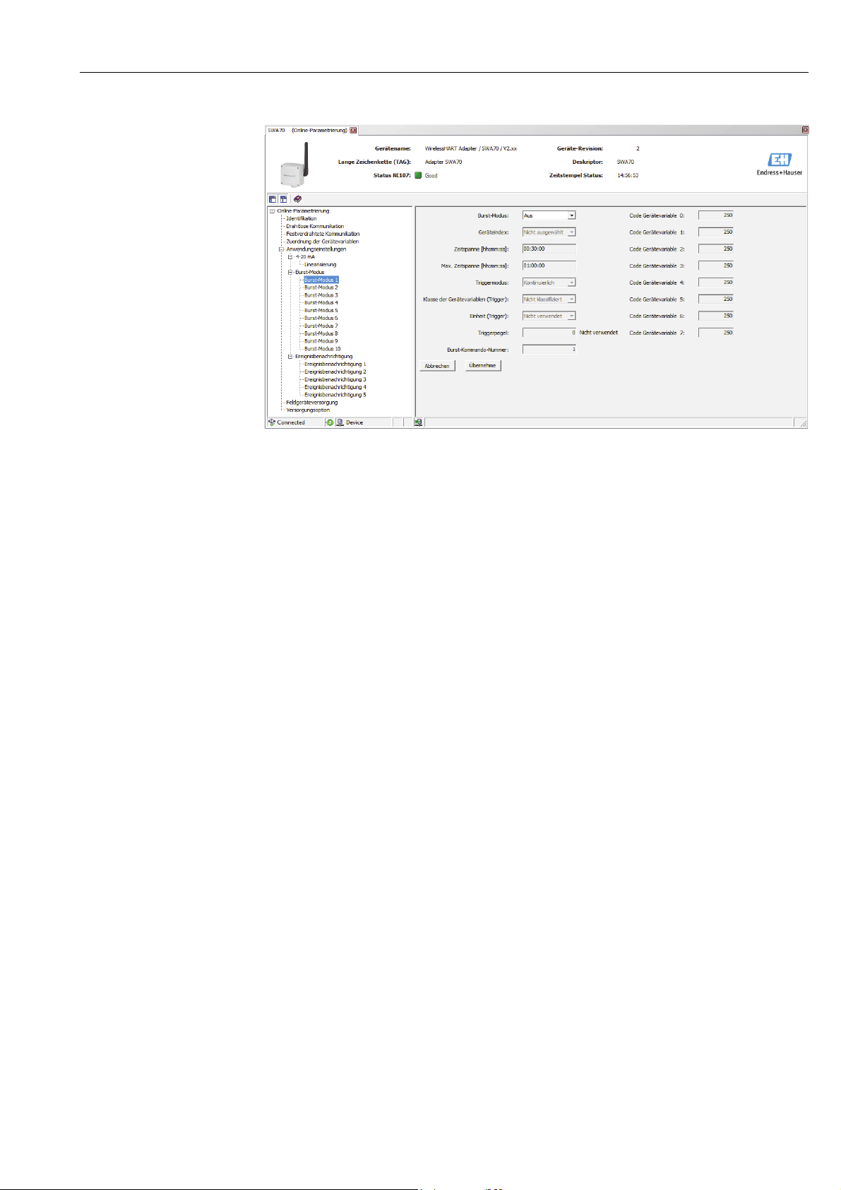
WirelessHART adapter SWA70 Configuration and online parameterization
In a typical configuration, the Primary Variable, Secondary Variable, Tertiary Variable
and Quaternary Variable process values are sent by the connected HART field device to the
Fieldgate at regular intervals. You can use burst command no. 3 and 48 for this purpose. We
recommend you set the same time frame for both commands.
The WirelessHART adapter "wakes" the field device, accepts the measured values and sends
them at the set interval.
We recommend configuring a second burst set for the adapter so that the information of the
WirelessHART adapter is also available for host applications in the Fieldgate. The Primary
Variable, Secondary Variable, Tertiary Variable and Quaternary Variable device
variables are configured in the "Device Variable Mapping" window. See “Device variable
mapping” on page 61.
Setting the burst mode Proceed as follows to set the burst mode:
1. Open the Burst Mode 1 window, for example.
2. Via the Burst Mode parameter select the Wireless option.
– The gray fields become white. It is possible to enter data.
3. Under Device Index select the connected field device from the list.
– If the field device is not listed, press the Scan Subdevices button in the Wired
Communication window.
4. Select the Trigger Mode. The Continuous default setting is a typical setting.
– Additional trigger fields turn white if a setting other than Continuous is selected. It
is possible to enter data. An example of this can be found in the "Process monitoring
parameters" table.
– For Period it is possible to enter a period after which a burst message is triggered in
an event, e.g. 2 minutes for a temperature alarm or 2 hours for the defined remaining
operating life of the battery unit.
– The value entered in the Max. Period field determines the maximum time that can
elapse between two burst messages if the trigger condition is not met.
Endress + Hauser 65
Page 66

Configuration and online parameterization WirelessHART adapter SWA70
5. For Period enter the interval (hh:mm:ss) at which the WirelessHART adapter should
send the process values.
– Please note that the shorter the interval, the more battery power is consumed.
6. Accept the default setting of 1 hour for Max. Period.
7. Enter the Burst Command Number. Command 3 is a typical setting. Here the primary
variable, secondary variable, tertiary variable and quaternary variable are sent.
– If you select command 9 or 33, the Device Variable Code 0-7 fields are enabled.
Further information can be found in the "Process monitoring parameters" table.
– If you select command 48, the device status is sent periodically.
8. Press Apply to save the settings in the WirelessHART adapter.
–Press OK to confirm.
– The burst mode takes effect immediately if the WirelessHART adapter is connected
to the network.
– If the WirelessHART adapter is not connected to the network, a message appears to
this effect. Press OK to confirm. The burst mode takes effect when the WirelessHART
adapter joins the network. This means that you can also configure the burst mode
offline.
Burst mode parameters
Parameter Meaning Example Default
Burst mode Specifies whether the burst mode is active.
• Off: the burst mode is not active, the input boxes are
grayed out and write-protected.
• Wireless: the burst mode is active, data can be entered in
the input boxes.
• The process monitoring parameters are written to the
WirelessHART adapter when the "Apply" button is
pressed.
Device Index Specifies the field device or WirelessHART adapter for
which the process monitoring parameters apply.
• The "Long Tag" entry is used for field devices with version
HART6 and higher.
• "Message" is used for field devices with HART 5 as these
devices do not support the "Long Tag" entry.
Period (hh:mm:ss) If the "Trigger Mode" is set to "Continuous" this parameter
specifies the length of time that elapses between two burst
messages. If another option was selected for the "Trigger
Mode" this period is used to specify the fastest rate. Refer to
fig. 10-1 and fig. 10-2.
Max. Period (hh:mm:ss) If the "Trigger Mode" is set to a value other than
"Continuous", this function is used to set the maximum
period in seconds that can elapse between two burst
messages if the condition ("Trigger Level") is not met.
Refer to fig. 10-1 and fig. 10-2.
Wireless Off
Tank 5
00:10:00 00:30:00
01:00:00 01:00:00
66 Endress + Hauser
Page 67

WirelessHART adapter SWA70 Configuration and online parameterization
Parameter Meaning Example Default
Trigger Mode Determines the event that triggers a burst message from
the device.
Options:
• Continuous: a burst message is sent continuously at
intervals. The interval is set via the "Period" parameter.
• Window: a burst message is sent after the set "Period" if
the process value deviates from the last communicated
value by more than the specified trigger level. In the case
of smaller deviations, the process value is sent at the set
"Max. Period". See figure 10-1 on page68.
• Rising: a burst message is sent after the set "Period" if the
process value rises above the specified trigger level. If the
process value remains below the trigger level, it is sent
after the set "Max. Period". See figure 10-2 on page69.
• Falling: a burst message is sent after the set "Period" if the
process value falls below the specified trigger level. If the
process value remains above the trigger level, it is sent
after the set "Max. Period".
• On Change: a burst message is sent after the set "Period" if
a value of the HART command changes.
Examples
• Example 1:
Setting: Trigger Mode: Continuous, Period: 00:10:00,
Burst Command Number: 3
Result: a field device sends all the measured values every
ten minutes.
• Example 2:
Settings: Trigger Mode: Falling, Period: 00:05:00, Max.
Period: 01:00:00, Device Variable Class (Trigger):
Volume, Unit Code (Trigger): l for liter, Trigger Level:
200, Burst Command Number: 3
Prerequisite (configured at field device): "Primary
Variable Unit" is "l" for liter
Result: a burst message is triggered once an hour as long
as the value is above 200 liters. If the value is below
200 liters, a burst message is triggered every 5 minutes.
Device Variable Class
(Trigger)
Unit Code (Trigger) Unit of the measured value l Not
Trigger Level Specifies the threshold for switching from "Period" to the
Burst Command
Number
Specifies the classification of the measurement.
This field is triggered either via the setting for "Period" or the
"Max. Period".
"Max. Period", i.e. from the fast to the slow setting.
– The switching mode is specified in the "Trigger Mode" .
Burst Command Number; more detailed information is
provided in the HART Specification.
• 1: transmits the value of the "Primary Variable" and the
unit
• 2: transmits the value of the 4 to 20 mA signal and the
corresponding value as a percentage
• 3: transmits the value of the 4 to 20 mA signal and up to
4 predefined process variables ("Primary Variable",
"Secondary Variable", "Tertiary Variable", "Quaternary
Variable") and the associated unit
• 9: transmits the value, unit and status of up to 8 field
device variables
• 33: transmits the value and unit of up to 4 field device
variables
• 48: transmits the complete device status
Continuous Continuous
Volume Not
Classified
Classified
200 0
31
Note:
• You can set any commands you want for connected field
devices. Please refer to the specific operating manual for
the commands.
• If in doubt, use commands 3 and 48.
• If command 48 is used only the "Continuous" trigger mode
can be used.
Endress + Hauser 67
Page 68
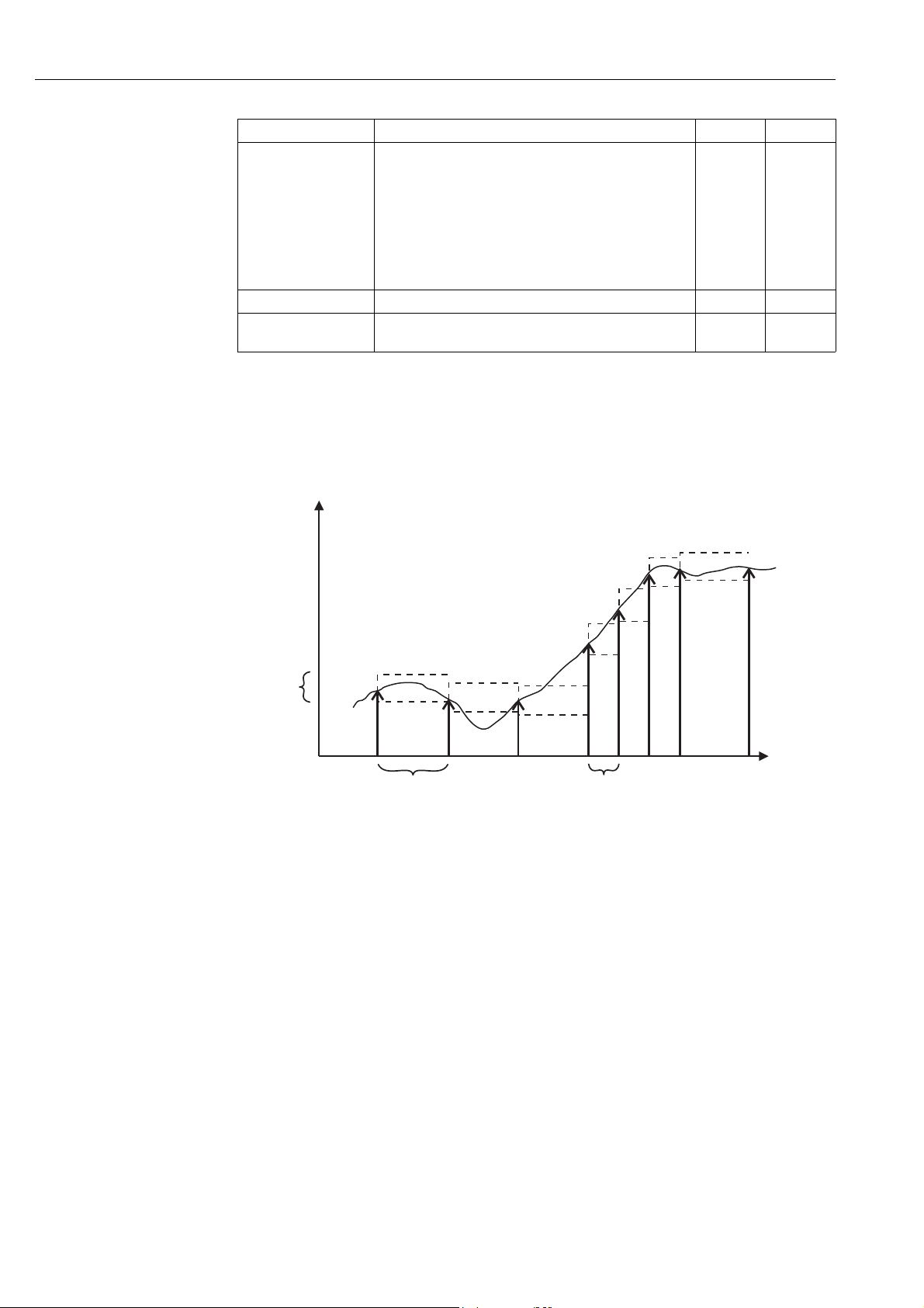
Configuration and online parameterization WirelessHART adapter SWA70
Parameter Meaning Example Default
Device Variable
Code 0-7
Cancel Press the button to reset the values to the default settings.
Apply Press the button to write the values to the WirelessHART
For selecting the device variables to be transmitted in the
burst message if command 9 or 33 have been selected as
the burst command number.
• Select the field device variable that is to be transmitted.
This is only possible for the WirelessHART adapter.
• If you want to set the burst mode for a connected field
device, refer to the operating manual of the field device
for information about the assignment of the device
variables.
adapter.
The graphic below illustrates how burst messages are sent for the "Window" trigger mode.
A burst message is sent after the set "Period" if the process value deviates from the last
communicated value by more than the defined "trigger window". In the case of smaller
deviations, the process value is sent at the set "Max. Period".
Trigger
window
Process
value
t
PeriodMax. period
Fig. 10-1: Transmission of burst messages for the "Window" trigger mode
68 Endress + Hauser
Page 69
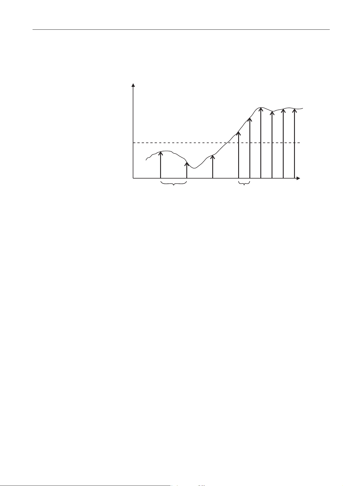
WirelessHART adapter SWA70 Configuration and online parameterization
The graphic below illustrates how burst messages are sent for the "Rising" trigger mode.
A burst message is sent after the set "Period" if the process value rises above the specified
trigger level. If the process value remains below the trigger level, it is sent after the set
"Max. Period".
Process
value
Trigger
window
t
PeriodMax. period
Fig. 10-2: Transmission of burst messages for the "Rising" trigger mode
10.7 Event notification (application setting)
Event notification is a special application similar to the burst mode. An event notification is
sent if there are changes in the device configuration or device status, regardless of whether
data are already being sent by burst mode commands. The status included in the device
status byte, the extended device status byte and in command 48 can be used for event
notification. It is possible to specify a specific number of bits that will trigger event
notification. Event notifications have a low priority, but carry a time stamp in order to record
the first time when notification was triggered. Up to 5 different event notifications can be
defined in the Event Notification 1 to Event Notification 5 windows.
1. Click Application Settings/Event Notification in the DTM navigation tree to display
the window with an overview of the event notifications.
– Wireless indicates that the specific event notification has already been configured.
– Off indicates that the specific event notification has not been configured.
Endress + Hauser 69
Page 70
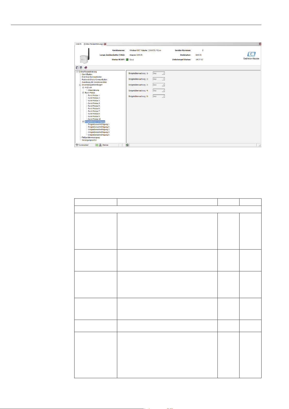
Configuration and online parameterization WirelessHART adapter SWA70
2. Click Application Settings/Event Notification in the DTM navigation tree and then select
Event Notification 1.
– You can enter text in the white fields. Press Enter to save your changes.
– The gray fields are read-only.
– An explanation of the parameters is provided in the following "Event notification
parameters" table. Mandatory fields are highlighted in bold.
Event notification
parameters
Parameter Meaning Example Default
"Event" tab
Event Notification
Control Code
Device Index Specifies the field device or WirelessHART adapter for
Event Notification
Retry Time
Maximum Update
Time
Event Debounce
Interval
Event Status Indicates whether event notification has been sent and not
Specifies whether the event notification mode is active.
• Off: the event notification mode is not active. The input
boxes are grayed out and write-protected.
• Wireless: the event notification mode is active. It is
possible to enter data in the input boxes.
The event notification parameters are written to the
WirelessHART adapter when the "Apply" button is pressed.
which the event notification parameters apply.
• "Long Tag"
• For field devices with HART 5 version: message
Period in hh:mm:ss between the transmission of event
notifications that have not been acknowledged.
– The system continues to transmit the event notifications
until the WirelessHART adapter gets confirmation of
receipt.
Maximum time in hh:mm:ss that is used if no event change
occurs
– If no event occurs, the WirelessHART adapter sends event
notification after this length of time.
The amount of time in hh:mm:ss that an event must last
before the event notification is sent out.
yet acknowledged.
• "Configuration Changed" event is pending: the
"Configuration Changed" event has not yet been
acknowledged.
• "Device Status" event is pending: the "Device Status" event
has not yet been acknowledged.
• "More Status Available" event is pending: the "More Status
Available" event has not yet been acknowledged.
Wireless Off
Tank 5
00:10:00 00:30:00
01:00:00 00:30:00
00:10:00 00:30:00
70 Endress + Hauser
Page 71

WirelessHART adapter SWA70 Configuration and online parameterization
Parameter Meaning Example Default
"Event" tab
First unACK Time Indicates (in hh:mm:ss) how long the event notification
shown under "Event Status" has been pending
"Standard Event Mask" tab
Tick the appropriate check boxes to activate the desired
event notification.
– The event notifications indicated on this tab are
standardized.
"Device-Specific Event Mask" tab
Byte, bit This tab contains the device-specific, non-standardized
event notifications
– They are described in the operating manual for the
particular field device and can be enabled accordingly.
3. Configure the event notification parameters in the Event tab.
Endress + Hauser 71
Page 72
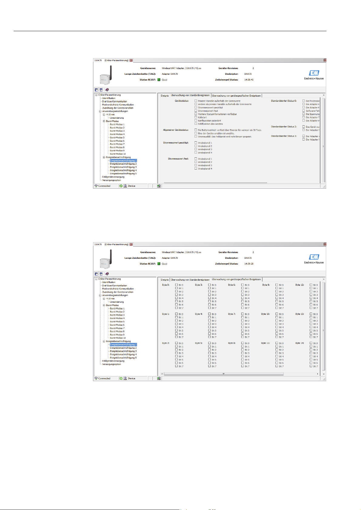
Configuration and online parameterization WirelessHART adapter SWA70
4. In the Standard Event Mask tab, click the standard events that you want to monitor.
5. Select the Device-Specific Event Mask tab to monitor the device-specific events of the
connected field device or the WirelessHART adapter.
– Check the operating manual of the connected field device before you select check
boxes on the Device-Specific Event Mask tab.
– An explanation of the parameters is provided in the following "Parameters for
monitoring device-specific events" table. Mandatory fields are highlighted in bold.
6. Press Apply to save the settings in the WirelessHART adapter.
–Press OK to confirm.
– The event is monitored immediately if the WirelessHART adapter is connected to the
network.
– If the WirelessHART adapter is not connected to the network, a message appears to
this effect. Press OK to confirm. The event takes effect when the WirelessHART
adapter joins the network.
– If the WirelessHART adapter is not connected to the network, you can also configure
event notification in the offline mode.
72 Endress + Hauser
Page 73
WirelessHART adapter SWA70 Configuration and online parameterization
Device-specific event
mask parameters
Byte Bit Meaning
0 0 No join attempt started so far.
1 The WirelessHART adapter is not connected to a WirelessHART network.
2 No alternative path to a neighbor.
3 The WirelessHART adapter does not have a join key.
4 The WirelessHART adapter could not connect to the WirelessHART network.
1 0 The WirelessHART adapter could not communicate with a field device.
1 The loop current is less than 2 mA.
2 The loop current exceeds the upper current limit value.
3 Startup voltage was not provided.
4 Operating voltage was not provided.
5 The WirelessHART adapter is in the configuration mode.
6 The WirelessHART adapter scans for connected devices.
7 The WirelessHART adapter has found more than four field devices.
2 0 The hardware of the WirelessHART adapter is defective.
1 The WirelessHART adapter is performing a self-test.
2 The temperature of the WirelessHART adapter is outside the specified range.
3 The hardware of the WirelessHART adapter is defective.
4 Number of write attempts to FLASH at a critical level.
6 Not used
5 Number of write attempts to FLASH at a maximum level.
7 The hardware of the WirelessHART adapter is defective.
3 0 The loop current has reached the configured lower warning level.
1 The loop current has reached the configured upper warning level.
2 The loop current has reached the configured lower alarm level.
3 The loop current has reached the configured upper alarm level.
4 Memory (lower part) contains no valid firmware update.
5 Memory (upper part) contains no valid firmware update.
6 There is an entry in the burst table or under event notification without an associated field
device.
4 0 First wired device has additional status information.
1 First wired device is not working correctly.
2 Second wired device has additional status information.
3 Second wired device is not working correctly.
4 Third wired device has additional status information.
5 Third wired device is not working correctly.
6 Fourth wired device has additional status information.
7 Fourth wired device is not working correctly.
5 0 - 7 Not used
6 0 Set: the battery unit has energy for less than 30 days and should be changed.
Reset: the battery unit has energy for more than 33 days.
1 One of the device variables is not valid.
2 Failure of power supply unit: field device is no longer powered.
7 0 - 7 Not used
8 0 Process values are simulated.
1 The hardware of the WirelessHART adapter is defective.
2 The hardware of the WirelessHART adapter is defective.
3 Software error: unexpected conditions.
4 The voltage of the WirelessHART adapter or the field device is too low.
5 Not used
6 The hardware of the WirelessHART adapter is defective.
9 0 - 7 Not used
10 0 - 7 Analog output is saturated.
11 0 A device was added to or removed from the list of field devices.
1 The WirelessHART adapter has discovered another master of same type.
Endress + Hauser 73
Page 74

Configuration and online parameterization WirelessHART adapter SWA70
Byte Bit Meaning
12 0 The WirelessHART adapter was unable to get the required bandwidth.
1 Not used
2 The WirelessHART adapter asked for bandwidth and is awaiting a response.
3 Firmware update in progress.
10.8 Field device power
The life of the battery unit can be optimized by aligning the power supply of the
WirelessHART adapter with the energy requirements of the connected device. Knowledge of
the energy requirements makes it possible to more reliably predict the battery service life.
The power supply parameters for the field device must be taken from the field device
operating manual. For some Endress+Hauser field devices the optimum power supply
parameters are provided in a database supplied with the DTM.
Note!
NOTE
To minimize power consumption, we recommend HART communication between the field
device and the WirelessHART adapter with a fixed analog current value of 4 mA in multidrop
mode.
1. Click Field Device Power in the DTM navigation tree to display the appropriate
parameters.
– You can enter text in the white fields. Press Enter to save your changes.
– The gray fields are read-only.
– The meaning of the individual parameters is illustrated in "fig. 10-3" and explained in
the "Field device power" table.
74 Endress + Hauser
Page 75
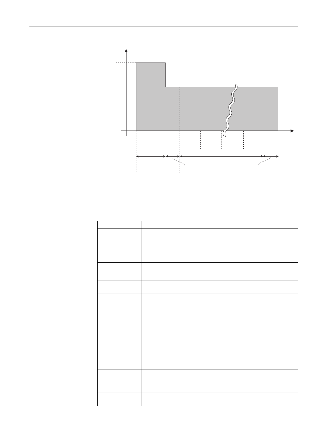
WirelessHART adapter SWA70 Configuration and online parameterization
V
Start-up
Voltage
Operating
Voltage
Parameters: field device
power
Power-On
External
t x
Time
after
Trigger
t off
t 0
Start-up
Voltage Time
Device
initializes
t 1
Lead
Command 1
Time
HART synchronization
t 2
Command 2
HART communication
Penultimate
command
Last
command
Additional
configuration time
Fig. 10-3: Field device power parameters
If the WirelessHART adapter powers the field device as described in the section entitled
"Two-wire field device with power supplied by the adapter", the mandatory fields highlighted
in bold must be filled in.
Parameter Meaning Example Default
Auto Power Setting This is a read-only parameter.
• Not in Use: this option is displayed if the connected field
device does not support this function or if several field
devices are connected.
In Use: the optimum settings for the power supply of the
connected field device are detected automatically.
Start-Up Voltage Terminal voltage required by the connected field device on
start up, in the range from 8 to 23 V, in increments of 0.1 V
(see figure 10-3 on page75).
Start-Up Time Time in seconds during which the field device needs the "Start-
Up Voltage".
Start-Up Current Current in milliampere that is used by the field device for the
duration of the "Start-Up Time".
Operating Voltage Terminal voltage in Volts which the field device requires
during normal operation after the "Start-Up Time".
Lead Time Time in seconds which the field device requires after the "Start-
Up Time" to provide valid measured values.
Power-On Time after
External Trigger
Time in seconds that the field device remains powered after
communication.
– Only applies for the "Automatic" event mode.
Configuration Time Time in seconds that the field device is powered for
configuration, e.g. via a display.
– Only applies for the "Configuration" event mode.
Field Device Database For field devices whose parameters are known from a
database provided: refer to the tables for the values you need
for the "Start-up Voltage", "Start-Up Time", "Start-Up Current",
"Operating Voltage" and "Lead Time" parameters.
Use Value from
Database
Press this button to write the parameters to the WirelessHART
adapter.
Not in Use
14 V 16 V
5 s 5 s
14 mA 14 mA
12 V 16 V
10 s 10 s
1 s 30 s
300 s 300 s
–
t
Endress + Hauser 75
Page 76
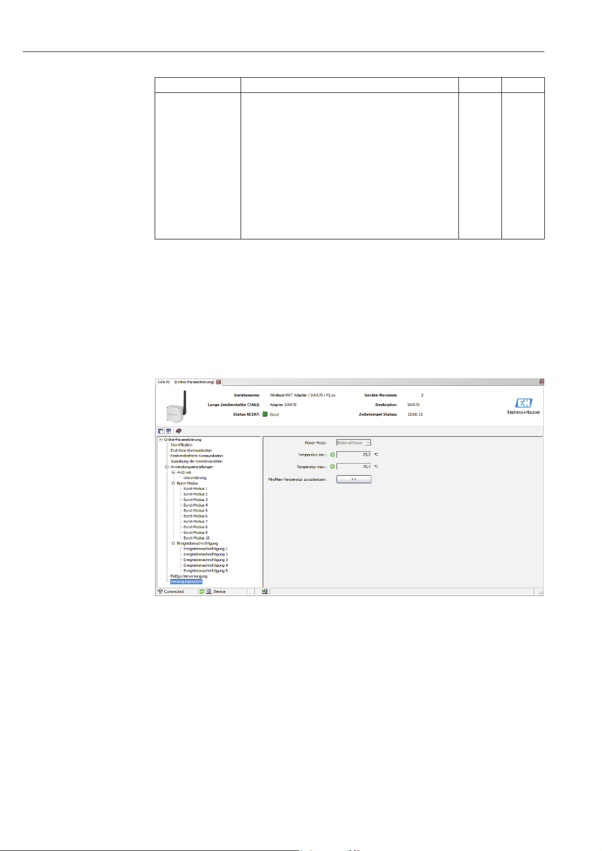
Configuration and online parameterization WirelessHART adapter SWA70
Parameter Meaning Example Default
Field Device Power
Mode
Specifies the power mode.
• Off: no communication takes place with any connected field
device. The WirelessHART adapter acts as a router between
other WirelessHART devices.
• Automatic: if commands are sent via wireless to the
connected field device, it receives power after each
communication as defined in the "Power-On Time after
External Trigger". This process prevents the power from
being constantly switched on and off.
• Configuration: if "Configuration" is selected, the connected
field device is powered for the "Configuration Time" and
afterwards returns to the "Automatic" mode. The same thing
happens when the push button on the WirelessHART
adapter is pressed for 10-15 seconds.
Automatic
10.9 Power option
The power options provide information about the power supply unit connected.
1. Click Power Option in the DTM navigation tree to display the appropriate parameters.
– You can enter text in the white fields. Press Enter to save your changes.
– The gray fields are read-only.
– An explanation of the individual parameters is provided in the "Power option" table.
76 Endress + Hauser
Page 77

WirelessHART adapter SWA70 Configuration and online parameterization
Parameters: power option
Parameter Meaning Example Default
Power Mode Indicates whether the adapter is powered by a battery or
externally.
Battery Changed This parameter only appears for battery-powered devices.
When the battery unit is replaced, this button must be pressed
so that the date for the "Last Battery Change" in the
WirelessHART adapter is set to the present date and the
expected lifetime calculation is reset.
Last Battery Change This parameter only appears for battery-powered devices.
Displays the date when the "Battery Changed" button was last
pressed.
– If the WirelessHART adapter is not connected to the
network during initial commissioning, the date is set to
01.01.1970.
– The date is updated when the adapter connects to the
network manager for the first time.
Temperature Min Lowest temperature in degrees Celsius to which the
WirelessHART adapter has been exposed. The value can be
reset.
Temperature Max Highest temperature in degrees Celsius to which the
WirelessHART adapter has been exposed. The value can be
reset.
Reset Temp Min/Max Press this button to reset the minimum and maximum
temperature values.
-10 °C
50 °C
Endress + Hauser 77
Page 78
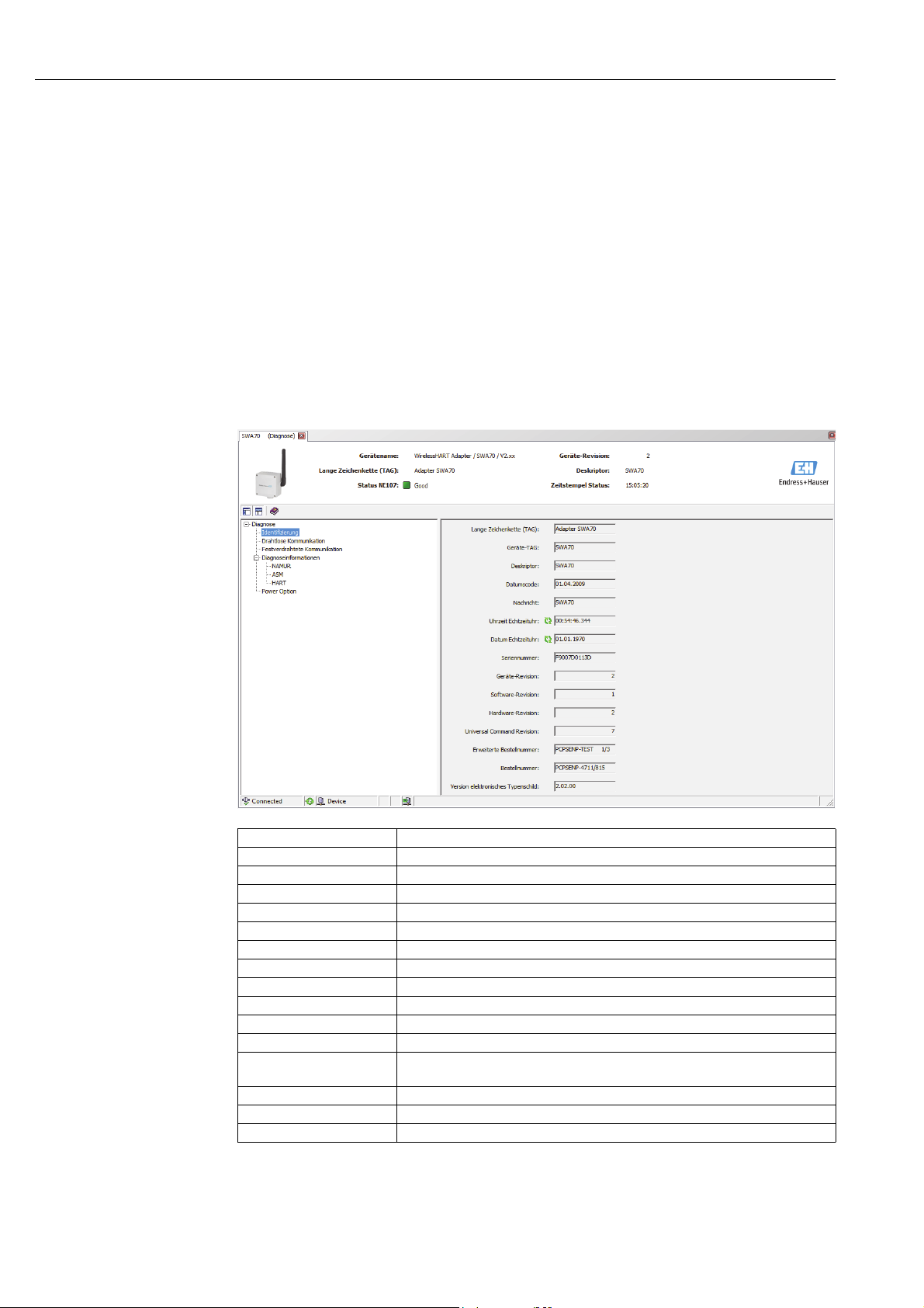
Additional DTM functions WirelessHART adapter SWA70
11 Additional DTM functions
11.1 Invoking the diagnostic parameters
For the purpose of diagnostics various parameters can be called up with the Diagnosis
function.
In the network view right-click the WirelessHART adapter and select Diagnosis in the
context menu. The Diagnosis window opens.
11.1.1 Identification
The Identification window contains information about the hardware and software of the
WirelessHART adapter. An explanation of the individual parameters is provided in the
"Identification parameters" table below.
Identification parameters
Parameter Meaning
Long Tag This is used to identify the WirelessHART adapter in the network and the plant
Device Tag This is used to identify the WirelessHART adapter in the network and the plant
Descriptor Helps the user describe the function or location of the WirelessHART adapter
Date Code Date in dd.mm.yyyy, indicating the date of the last change, for instance
Message Message that can be used as required
Real Time Clock Time Network system time
Real Time Clock Date Network system date
Serial Number Serial number of the WirelessHART adapter
Device Revision Device version of the WirelessHART adapter
Software Revision Software version of the WirelessHART adapter
Hardware Revision Hardware version of the WirelessHART adapter
Universal Command
Revision
Order Code Order code of the WirelessHART adapter
Ext. Order Code Extended order code
ENP Version Version of the electronic nameplate of the WirelessHART adapter
Version of the HART protocol that is supported by the WirelessHART adapter
78 Endress + Hauser
Page 79

WirelessHART adapter SWA70 Additional DTM functions
11.1.2 Wireless communication
The Wireless Communication window contains information about the operation of the
WirelessHART adapter. This information is updated every five minutes. An explanation of
the individual parameters is provided in the "Wireless communication parameters" table
below.
Wireless communication
parameters
Parameter Meaning
Network Identification Identification number of the network the WirelessHART adapter is joining
MAC Media Access Control (MAC) address
Nickname Nickname of the WirelessHART adapter for internal use in the network
Total Number of Neighbors Number of WirelessHART devices that were found in the vicinity of the
WirelessHART adapter and to which a connection has been made.
Wireless Health Status Key parameters for network communication
• Index: ID of the neighboring device
• Nickname: nickname of the neighboring device
• Mean RSL dBm: mean signal strength of the neighbor since the time when the
WirelessHART adapter joined the network
• Packets Transmitted: number of packets that have been sent by the
WirelessHART adapter since the adapter joined the network
• Failed Transmits: number of packets that have been sent by the WirelessHART
adapter and did not reach their intended destination (after retries) since the
adapter joined the network
• Packets Received: number of packets which the WirelessHART adapter has
received since the adapter joined the network
Endress + Hauser 79
Page 80
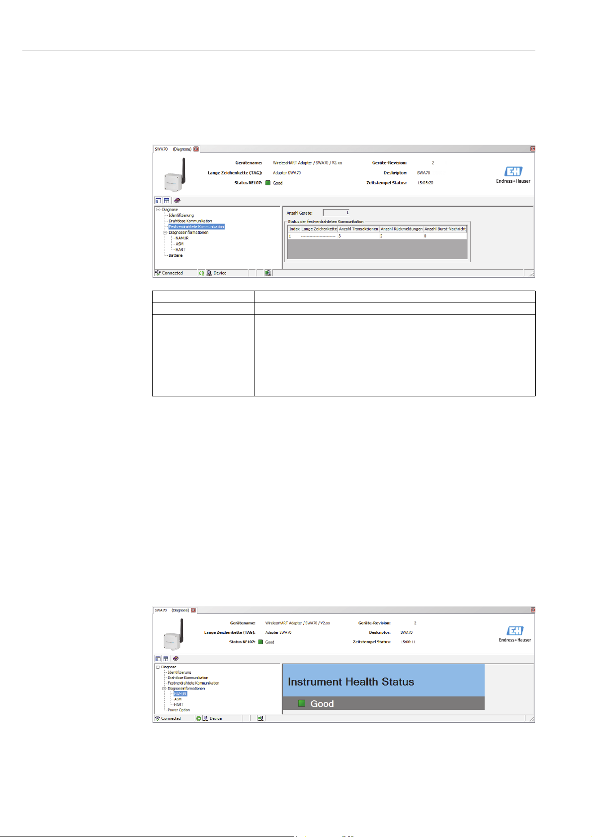
Additional DTM functions WirelessHART adapter SWA70
11.1.3 Wired communication
The Wired Communication window contains information about the HART field device that
is connected to the WirelessHART adapter. An explanation of the individual parameters is
provided in the "Wired communication parameters" table below.
Wired communication
parameters
Parameter Meaning
Number of Devices Number of HART field devices that are connected to the WirelessHART adapter
Wired Communication
Status
Key parameters for network communication
• Index: ID of the neighboring device
• Long Tag or Message: long tag of the neighboring device
• STX Count: number of data transmissions that have been triggered by the
WirelessHART adapter
• ACK Count: number of feedback messages which the WirelessHART adapter has
received from HART devices
• BACK Count: number of burst messages
11.1.4 Instrument health
The Health Status window contains information about the health of the device. This
information is displayed in three different ways in accordance with the following guidelines:
• NAMUR guideline NE 107
• ASM guidelines
• HART Specification
NAMUR NE 107 Open the NAMUR window to see the current device health status classified according to the
following scheme:
• Good
• Failure (F)
• Maintenance required (M)
• Out of Specification (S)
• Function Check (C)
80 Endress + Hauser
Page 81
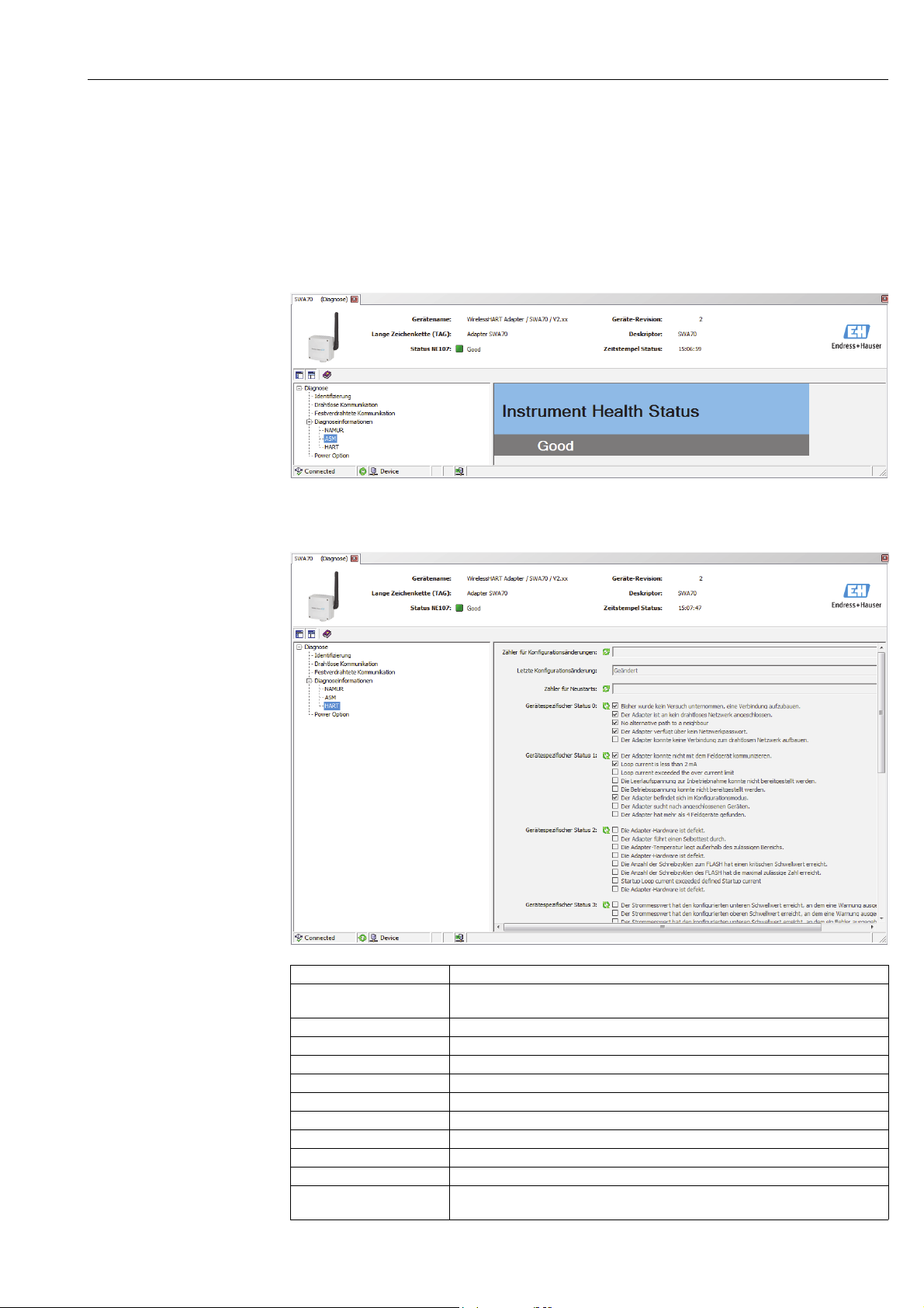
WirelessHART adapter SWA70 Additional DTM functions
ASM Open the ASM window to see the current device health status classified according to the
following scheme:
• Good
• Faults in the sensor or actuator element
• Faults in the electronics
• Installation faults, fault during start-up
• Faults due to process influence, faults due to non-compliance with specified operating
conditions
HART Open the HART window to see the current device health status classified according to the
"HART diagnosis parameters" table. Ticked check boxes indicate active conditions:
HART diagnosis
parameters
Parameter Meaning
Configuration Change
Counter
Configuration Changed Flag Flags a change in the configuration since the last communication
Reboot counter Counts the number of reboots
Device-Specific Status 0 Displays the network status
Device-Specific Status 1 Displays the status for wired communication
Device-Specific Status 2 Displays the status for internal wireless communication
Device-Specific Status 3 Displays the status of the current signal for the connected field device
Device-Specific Status 4 Indicates a malfunction in the field device
Extended Device Status Indicates the general status of the field device
Standardized Status 0 Indicates the status of the WirelessHART adapter
Analog Channel Saturated Indicates that the current signal for the connected field device exceeds the end of
Counts the changes in the configuration
range value for the input current
Endress + Hauser 81
Page 82
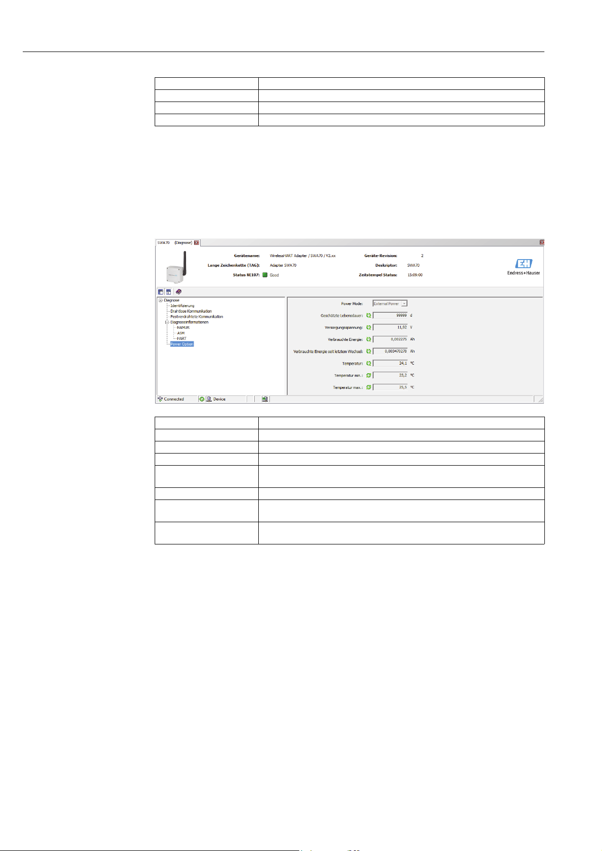
Additional DTM functions WirelessHART adapter SWA70
Parameter Meaning
Standardized Status 2 Displays the standardized status for the wired HART connection
Standardized Status 3 Displays the standardized status of the network
Real Time Clock Time Displays the time
Refer also to the table "Device-specific event mask parameters" on page73.
11.1.5 Power Option
The Power Option window contains information about the battery unit of the
WirelessHART adapter. An explanation of the individual parameters is provided in the
"Power Option parameters" table below.
Power Option parameters
Parameter Meaning
Estimated Lifetime Estimated battery life in days under the current conditions
Battery Voltage Current battery voltage
Consumed Energy The charge drawn from the battery
Energy consumed since the
last change
Temperature Current temperature of the WirelessHART adapter
Temperature Min Minimum temperature of the WirelessHART adapter since the last time the
Temperature Max Maximum temperature of the WirelessHART adapter since the last time the
Energy consumed under normalized conditions
temperature was reset
temperature was reset
82 Endress + Hauser
Page 83
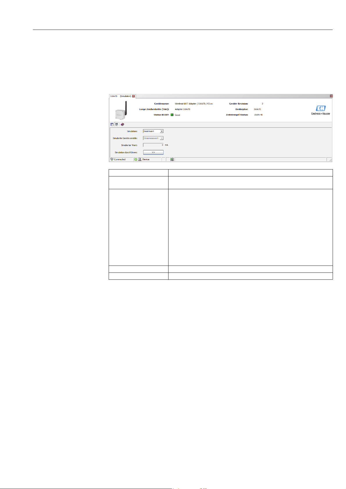
WirelessHART adapter SWA70 Additional DTM functions
11.2 Simulation
The Simulation function makes it possible to simulate adapter parameters. If the simulation
is activated by selecting the Disabled value in the Simulation parameter, adapter variables
can be chosen from a list. After assigning a value, simulation can be started by pressing the
Execute Simulation button.
Simulation parameters
Parameter Meaning
Simulation • Disabled: simulation mode is disabled
• Enabled: simulation mode is enabled
Simulated Device Variable List of adapter variables that can be simulated
• Battery Voltage
• Battery Voltage With Load: battery voltage with a load
• Battery Voltage Without Load During Battery Test
• Consumed Energy: charge drawn from the battery
• Estimated Lifetime: estimated lifetime of the battery
• Scaled Loop Current
• Normalized Consumed Energy: energy consumed since the last battery change
• RSL of Best Neighbor: signal strength of the "best" neighbor
• RSL of Second Best Neighbor: signal strength of the "second-best" neighbor
• Temperature
• Temperature Min: minimum temperature since the last reset
• Temperature Max: maximum temperature since the last reset
Simulated Value Field for entering the simulated value
Execute Simulation Press the button to start the simulation
Endress + Hauser 83
Page 84
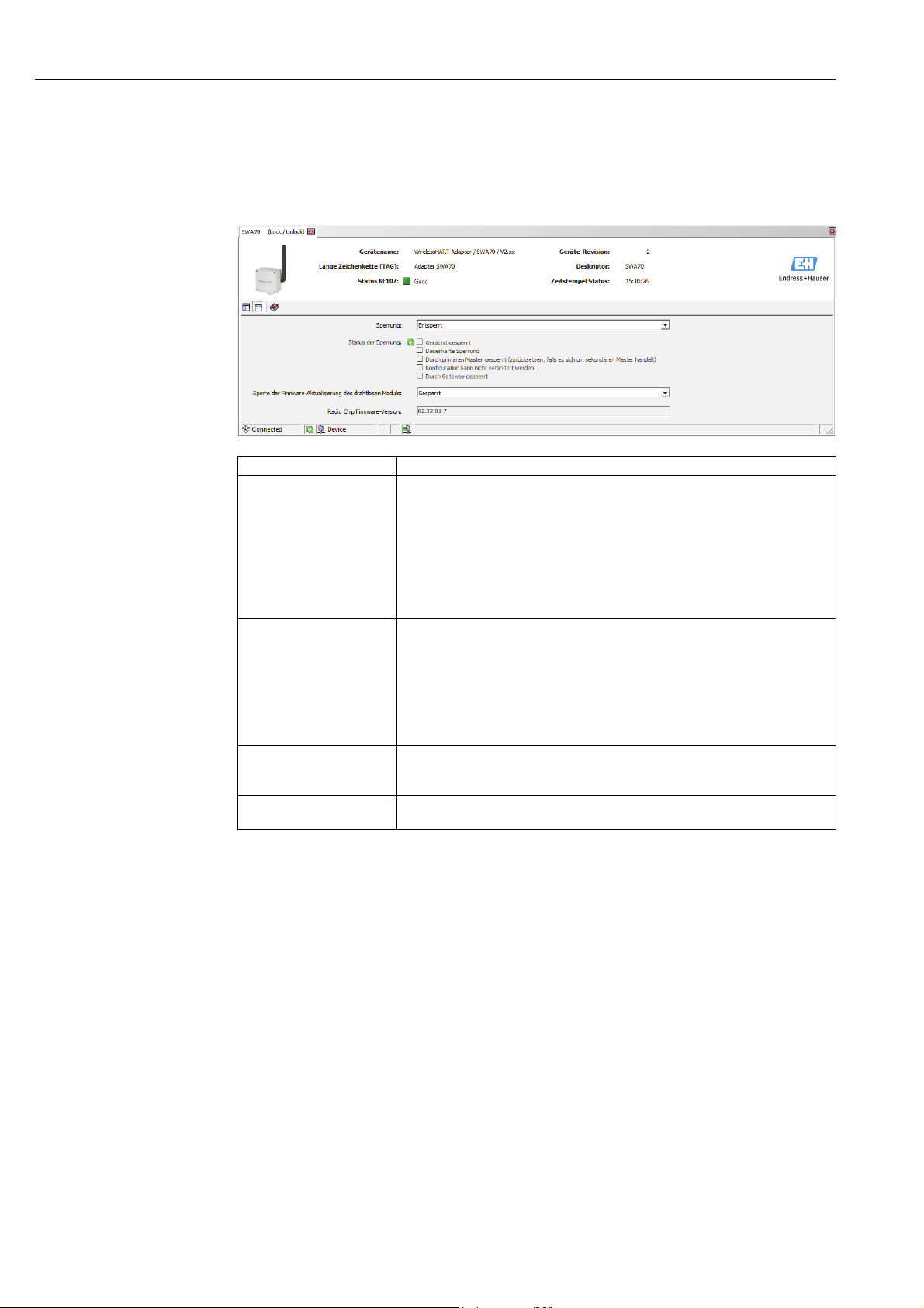
Additional DTM functions WirelessHART adapter SWA70
11.3 Access control
The Lock/Unlock function allows the user to protect the WirelessHART adapter from
unauthorized access. An explanation of the individual parameters is provided in the "Access
control parameters" table below.
Access control parameters
Parameter Meaning
Lock Code • Unlocked: the WirelessHART adapter is not protected. All the parameters can be
edited.
• Lock Temporary: the WirelessHART adapter is locked. A device reset or power
loss will unlock the adapter.
• Lock Permanent: the WirelessHART adapter is permanently locked. A device
reset or power loss will not unlock the adapter.
• Lock All: all the masters are locked.
In the case of all of the locks, it is possible to unlock the adapter again by changing
the "Lock Code" parameter.
Lock Status The selected check boxes indicate the access status of the WirelessHART adapter
• Device Locked: locked
• Lock is Permanent: permanently locked
• Locked by Primary Master (Reset if Secondary Master): the WirelessHART
adapter has been locked by the Primary Master. A Secondary Master must be
restarted to unlock the adapter.
• Configuration cannot be changed: it is not possible to modify the configuration.
• Locked by Gateway: the lock was triggered by the gateway.
Wireless Module Firmware
Update Lock
Radio Chip Firmware
Version
• Unlocked: the firmware of the WirelessHART adapter's radio module can be
downloaded.
• Locked: the firmware of the WirelessHART adapter cannot be downloaded.
Firmware version of the radio module
84 Endress + Hauser
Page 85

WirelessHART adapter SWA70 Additional DTM functions
11.4 Updating the firmware
The Update Firmware function allows users to download new firmware for the
WirelessHART adapter from an FTP server. To be able to do so, the Wireless Module
Firmware Update Lock parameter in the Lock/Unlock window must first be set to
Unlocked. An explanation of the individual parameters is provided in the "Firmware update
parameters" table below.
Firmware update
parameters
Parameter Meaning
Update Via Choose whether the firmware is uploaded via the FTP server or a local directory
FW Update File (Path) URL of the FTP server or path and file name on a local storage medium
FTP User User name for the FTP server
FTP Password User password for the FTP server
Update Firmware Press this button to update the firmware
Firmware Version Current version of the firmware of the WirelessHART adapter
Radio Chip Firmware
Version
Firmware version of the radio module
Endress + Hauser 85
Page 86

Additional DTM functions WirelessHART adapter SWA70
11.5 Device DTM information
The Device DTM Info function displays standardized information about the WirelessHART
adapter which is operated by the DTM. An explanation of the individual parameters is
provided in the "Device DTM info parameters" table below.
Device DTM info
parameters
Parameter Meaning
ENP Version Version of the electronic nameplate of the WirelessHART adapter
Device Tag Is used to identify the field device in the network
Serial Number Serial number of the WirelessHART adapter
Ext. Order Code Order code of the WirelessHART adapter
Firmware Version Current version of the firmware of the WirelessHART adapter
11.6 Self-test
The Perform Self-Test function causes the WirelessHART adapter to perform a self-test.
The result is displayed in the Diagnosis window as described in Section 9.3 "Invoking the
diagnostic parameters".
86 Endress + Hauser
Page 87

WirelessHART adapter SWA70 Maintenance and repair
12 Maintenance and repair
With the exception of replacing the battery unit, no special maintenance work is required for
the WirelessHART adapter.
12.1 Replacing the battery unit
You can order the power supply units from your local Endress+Hauser sales partner.
See “Accessories and spare parts” on page 89.
You must first open the housing to replace the power supply unit. Follow the instructions in
the “Operational safety” on page 7. When disposing of the battery unit, pay attention to the
information in the section “Battery unit” on page 88.
You require the following tool: Torx T10.
Warning!
• The housing of the WirelessHART adapter may not be opened in hazardous areas if dust
is present. The battery unit can only be replaced in a dusty atmosphere if adequate
ventilation ensures the environment is free of dust.
• The battery unit may be replaced in the presence of gas in a hazardous area.
NOTE
Proceed as follows to replace the battery unit:
1. Switch off the power supply. Make sure that the unit is not live.
2. Open the housing of the WirelessHART adapter by unscrewing the four housing screws.
3. Remove the connecting cable for the power supply unit from the socket on the PCB
cover.
4. Simultaneously press the two clips of the power supply unit towards the middle of the
power supply unit and remove the unit.
5. Insert the new power supply unit into the compartment. In doing so, ensure that the two
clips make an audible click when engaging in the indentations at the top and bottom of
the compartment.
6. Insert the connecting cable for the power supply unit into the socket on the PCB cover.
Note!
• Please note that after replacing a battery unit the "Battery Changed" button must be
pressed in the DTM so that the date for the "Last Battery Change" in the WirelessHART
adapter is set to the present date. See “Field device power” on page 74.
Endress + Hauser 87
Page 88

Maintenance and repair WirelessHART adapter SWA70
12.2 Return
The measuring device must be returned if repairs or a factory calibration are required, or if
the wrong device has been ordered or delivered. According to legal regulations
Endress+Hauser, as an ISO-certified company, is required to follow certain procedures when
handling returned products that are in contact with the medium.
To ensure safe, swift and professional device returns, please refer to the procedure and
conditions for returning devices provided on the Endress+Hauser website
www.services.endress.com/return-material
In the case of devices with a battery unit, the battery unit must be removed before the device
is returned.
Warning!
• If Endress+Hauser requests you to return the battery unit, please pay attention to the
Safety Data Sheet and the local transportation conditions.
12.3 Disposal
12.3.1 WirelessHART adapter
Dispose of the WirelessHART adapter in accordance with the regulations that apply in your
country.
In the case of device versions with a battery unit, pay attention to the information in the
following section to dispose of the battery unit.
12.3.2 Battery unit
When disposing of the battery unit, please observe national regulations governing the
disposal of lithium-thionyl chloride high-power batteries in your country, and pay attention
to the Safety Data Sheet (Material Safety Data Sheet).
The battery unit is non-hazardous when used according to the recommendations of the
manufacturer. It does, however, contain hazardous substances.
In Germany there is a law that regulates the return of used batteries. You can return your
battery unit to Batterien-Montage-Zentrum GmbH (BMZ), a company specializing in
batteries. (www.bmz-gmbh.de). Please observe the German regulations when returning
battery units in Germany. The sender bears the costs incurred.
12.4 Contact addresses at Endress+Hauser
Contact addresses can be found on our homepage: www.addresses.endress.com/worldwide.
If you have any questions, please contact your Endress+Hauser branch office.
88 Endress + Hauser
Page 89

WirelessHART adapter SWA70 Maintenance and repair
12.5 Accessories and spare parts
Various accessories, which can be ordered separately from Endress+Hauser, are available for
the WirelessHART adapter:
• 71092238: battery unit SWA70
• 71093078: mounting bracket, wall/pipe; steel 316L
• 71093795: cable gland
• 71093797: adapter set M20/M20
• 71093798: adapter set M20/G 1/2
• 71093799: adapter set M20/NPT 1/2
• 71093800: adapter set M20/NPT 3/4
Endress + Hauser 89
Page 90

Troubleshooting WirelessHART adapter SWA70
13 Troubleshooting
Error messages are displayed in the Diagnosis window of the DTM as described in the
"Invoking the diagnostic parameters" section. See “Invoking the diagnostic parameters” on
page 78.
The table below lists problems which might occur during commissioning and operation of
the WirelessHART adapter.
Problem Solution
1 FieldCare is communicating with the adapter via
a HART modem. FieldCare cannot find the
WirelessHART adapter when communicating via
a HART modem.
2 The WirelessHART adapter should supply power
to a two-wire field device. Power is not supplied
to the field device.
3 The WirelessHART adapter supplies power to a
two-wire field device. The WirelessHART
adapter is unable to find the field device and/or
the two devices do not communicate with one
another.
• The wrong address range has been selected in the
HART communication DTM. 15 is the default address
for the WirelessHART adapter.
– Select the address range such that the address of the
WirelessHART adapter is in this range.
• The computer has not used the same USB or COM port
that was specified when configuring the HART modem.
– Configure the HART communication DTM again or
use the correct port.
• The power supply unit is not plugged in.
– Check the "power" connector.
• The battery unit is empty or not plugged in.
– Check the "power" connector and replace the battery
unit if necessary.
– A simple check is to shake the battery unit: if you
hear liquid this means that the battery unit still has
life. Following a short-circuit, however, the battery
no longer works even if liquid can be heard.
• The power supply parameters have not been
configured correctly.
– Refer to the operating manual of the connected field
device for the appropriate values or ask the
manufacturer.
– Set the correct values in the SWA70-DTM.
• The field device does not support the HART protocol.
– The parameters can only be read by a HART field
device.
• The wrong address range has been selected in the
SWA70 DTM.
– Check whether the address range is correct.See
“Wired communication” on page 59.
• The power supply is switched off before the field device
can communicate
– Increase the "Lead Time" power supply parameter in
increments of 10 seconds until the error no longer
occurs.
• The WirelessHART adapter was started without
connecting the field device to terminals 1 and 2.
– Connect the field device to the WirelessHART
adapter at terminals 1 and 2. Start the
WirelessHART adapter. For this, either perform a
reset or disconnect and then reconnect the power
supply.
90 Endress + Hauser
Page 91

WirelessHART adapter SWA70 Troubleshooting
Problem Solution
4 The WirelessHART adapter is connected to a
four-wire field device or a control loop. The
WirelessHART adapter is unable to find the field
device and/or the WirelessHART adapter and
field device do not communicate with one
another.
5 A field device is connected via terminals 1 and 2
or 2 and 3 and the HART modem is connected to
terminals 7 and 8. FieldCare is unable to find a
connected HART field device.
6 The WirelessHART adapter cannot join the
network.
7 Adapter disappears sporadically from the
network
8 The WirelessHART adapter does not restart after
disconnecting and connecting the "power"
connector.
• The wrong address range has been selected in the
SWA70 DTM.
– Check whether the address range is correct. See
“Wired communication” on page 59.
• The wrong connection polarity was selected for a fourwire field device.
– Make the connection correctly. See “Four-wire field
device” on page 26.
• The PLC or remote I/O and a connected modem
dominate communication in a control loop. The
WirelessHART adapter automatically switches to the
slave mode.
– Remove the modem and make sure that the
WirelessHART adapter is configured as the
"Secondary Master" if the PLC or remote I/O is
configured as the "Primary Master".
• If the modem is connected to terminals 5 and 6 or
terminals 7 and 8, HART communication is not
forwarded to terminals 1 and 2 or 2 and 3 (desired
implementation)
– Connect the modem to terminals
1 and 2 or 2 and 3 so communication can be
established simultaneously with the WirelessHART
adapter and the field device. In the HART
communication DTM, the address range must be
adapted to suit the address of the field device.
• Check the following points if the WirelessHART
adapter does not connect to the Fieldgate. It can take a
few minutes for the adapter to join the network.
– Check whether the power supply unit is connected
correctly.
– Check whether the electronically controlled power
supply unit is operational. The yellow LED 3 is lit as
long as the buffer of the power supply unit is
charging. See “Light emitting diodes” on page 51.
– Check whether the Fieldgate and the WirelessHART
adapter have the same network ID and the same
network access key.
– Check that the WirelessHART adapter is mounted
correctly. See “Installation” on page 15.
– Check whether the WirelessHART adapter attempts
to join the network. If not, start a new connection
attempt by pressing the push button for 5 to
10 seconds. The attempt to join the network is
indicated as described in the "Display" section.
See “Display” on page 49.
• In the "Wireless Communication" window check the
number of neighbors in the "Diagnosis" function.
See “Wireless communication” on page 79.
– The WirelessHART adapter should have at least two
neighbors in a stable network. Three neighbors are
recommended in a noisy environment.
• The WirelessHART adapter shuts down when the
internal power storage units are discharged and the
"power" connector is plugged out.
Proceed as follows:
1 Disconnect the connector of the power supply unit
from the socket.
2 Press the push button for three seconds.
3 Wait for one minute.
4 Plug the battery connector back in.
Endress + Hauser 91
Page 92

Technical data WirelessHART adapter SWA70
14 Technical data
www.endress.com For the technical data, see the Technical Information document for "WirelessHART Adapter
SWA70" (TI00026S).
W@M Device Viewer Alternatively you can download all the related technical documentation via the W@M
Device Viewer. Enter the serial number of the WirelessHART on the website
"www.endress.com/deviceviewer". You can find the serial number on the nameplate.
92 Endress + Hauser
Page 93

WirelessHART adapter SWA70 Index
Index
Numerics
4-20 mA . . . . . . . . . . . . . . . . . . . . . . . . . . . . . . . . . . . . . . . 62
A
Access control . . . . . . . . . . . . . . . . . . . . . . . . . . . . . . . . . . 84
Accessories . . . . . . . . . . . . . . . . . . . . . . . . . . . . . . . . . . . . . 89
Angle bracket. . . . . . . . . . . . . . . . . . . . . . . . . . . . . . . . . . . 18
Antenna . . . . . . . . . . . . . . . . . . . . . . . . . . . . . . . . . . . . . . . 16
Applications . . . . . . . . . . . . . . . . . . . . . . . . . . . . . . . . . . . . . 7
ASM. . . . . . . . . . . . . . . . . . . . . . . . . . . . . . . . . . . . . . . . . . . 81
B
Battery compartment . . . . . . . . . . . . . . . . . . . . . . . . . 16, 53
Battery connector . . . . . . . . . . . . . . . . . . . . . . . . . . . . . . . 53
Battery status . . . . . . . . . . . . . . . . . . . . . . . . . . . . . . . . . . . 50
Battery unit. . . . . . . . . . . . . . . . . . . . . . . . . . . . . . . . . . . . . . 8
Electrical installation. . . . . . . . . . . . . . . . . . . . . . . . . . 22
Inserting and connecting . . . . . . . . . . . . . . . . . . . . . . 53
Burst mode . . . . . . . . . . . . . . . . . . . . . . . . . . . . . . . . . . . . . 64
Settings . . . . . . . . . . . . . . . . . . . . . . . . . . . . . . . . . . . . . 65
C
Cable entry . . . . . . . . . . . . . . . . . . . . . . . . . . . . . . . . . . . . . 16
Primary . . . . . . . . . . . . . . . . . . . . . . . . . . . . . . . . . . . . . 16
Secondary . . . . . . . . . . . . . . . . . . . . . . . . . . . . . . . . . . . 16
Cable specification. . . . . . . . . . . . . . . . . . . . . . . . . . . . 33, 42
Field device . . . . . . . . . . . . . . . . . . . . . . . . . . . . . . . 33, 42
CE mark. . . . . . . . . . . . . . . . . . . . . . . . . . . . . . . . . . . . . . . . . 9
Commissioning . . . . . . . . . . . . . . . . . . . . . . . . . . . . . . . 7, 52
Communication status . . . . . . . . . . . . . . . . . . . . . . . . . . . 49
Configuration . . . . . . . . . . . . . . . . . . . . . . . . . . . . . . . . 51, 55
Connector . . . . . . . . . . . . . . . . . . . . . . . . . . . . . . . . . . . . . . 48
Contact addresses . . . . . . . . . . . . . . . . . . . . . . . . . . . . . . . 88
Cover . . . . . . . . . . . . . . . . . . . . . . . . . . . . . . . . . . . . . . . . . . 16
D
Declaration of Conformity . . . . . . . . . . . . . . . . . . . . . . . . . 9
Design . . . . . . . . . . . . . . . . . . . . . . . . . . . . . . . . . . . . . . . . . 16
Designated use. . . . . . . . . . . . . . . . . . . . . . . . . . . . . . . . . . . 7
Device DTM information. . . . . . . . . . . . . . . . . . . . . . . . . . 86
Device structure . . . . . . . . . . . . . . . . . . . . . . . . . . . . . . . . . 16
Device variable mapping. . . . . . . . . . . . . . . . . . . . . . . . . . 61
Diagnostic parameters . . . . . . . . . . . . . . . . . . . . . . . . . . . 78
Display elements . . . . . . . . . . . . . . . . . . . . . . . . . . . . . . . . 48
Electronically controlled power supply units . . . . . . 50
Disposal
Battery unit. . . . . . . . . . . . . . . . . . . . . . . . . . . . . . . . . . 88
WirelessHART adapter . . . . . . . . . . . . . . . . . . . . . . . . 88
E
Electrical connection
Field device and SWA70 with DC power unit . . . . . 42
Field device and SWA70 with wide range
power unit. . . . . . . . . . . . . . . . . . . . . . . . . . . . . . . . . . . 33
Electrical installation
SWA70 with battery unit . . . . . . . . . . . . . . . . . . . . . . 22
SWA70 with DC power unit. . . . . . . . . . . . . . . . . . . . 40
SWA70 with wide range power unit. . . . . . . . . . . . . 30
Electrical symbols . . . . . . . . . . . . . . . . . . . . . . . . . . . . . . . 10
Error message . . . . . . . . . . . . . . . . . . . . . . . . . . . . . . . . . . 50
Event notification . . . . . . . . . . . . . . . . . . . . . . . . . . . . . . . 69
F
Field devices with wireless. . . . . . . . . . . . . . . . . . . . . . . . 14
Firmware
Updating. . . . . . . . . . . . . . . . . . . . . . . . . . . . . . . . . . . . 85
Fixing bracket . . . . . . . . . . . . . . . . . . . . . . . . . . . . . . . . . . 20
Fixing nut . . . . . . . . . . . . . . . . . . . . . . . . . . . . . . . . . . . . . . 16
Four-wire field device . . . . . . . . . . . . . . . . . . . . . . . . . . . . 38
Function . . . . . . . . . . . . . . . . . . . . . . . . . . . . . . . . . . . . . . . 14
H
HART . . . . . . . . . . . . . . . . . . . . . . . . . . . . . . . . . . . . . . . . . 81
Hazardous area . . . . . . . . . . . . . . . . . . . . . . . . . . . . . . . . . . . 7
Health Status . . . . . . . . . . . . . . . . . . . . . . . . . . . . . . . . . . . 80
I
Identification . . . . . . . . . . . . . . . . . . . . . . . . . . . . . 11, 55, 78
Installation . . . . . . . . . . . . . . . . . . . . . . . . . . . . . . . . . . . 7, 15
Direct mounting. . . . . . . . . . . . . . . . . . . . . . . . . . . . . . 17
On a pipe. . . . . . . . . . . . . . . . . . . . . . . . . . . . . . . . . . . . 20
On the field device. . . . . . . . . . . . . . . . . . . . . . . . . . . . 17
On the wall . . . . . . . . . . . . . . . . . . . . . . . . . . . . . . . . . . 18
Remote . . . . . . . . . . . . . . . . . . . . . . . . . . . . . . . . . . . . . 18
Installation conditions . . . . . . . . . . . . . . . . . . . . . . . . . . . 15
Instrument health . . . . . . . . . . . . . . . . . . . . . . . . . . . . . . . 80
L
Light emitting diode . . . . . . . . . . . . . . . . . . . . . . . . . . . . . 53
Green, battery status. . . . . . . . . . . . . . . . . . . . . . . 48, 50
Red, communication, error messages . . . . . . . . . 48, 50
Yellow, communication status . . . . . . . . . . . . . . . 48–49
Light emitting diodes
Electronically controlled power supply units . . . . . . 51
Linearization . . . . . . . . . . . . . . . . . . . . . . . . . . . . . . . . . . . 63
Lock/Unlock. . . . . . . . . . . . . . . . . . . . . . . . . . . . . . . . . . . . 84
M
M12 socket
Assembly and disassembly. . . . . . . . . . . . . . . . . . 32, 41
Connection . . . . . . . . . . . . . . . . . . . . . . . . . . . . . . . 32, 41
Maintenance . . . . . . . . . . . . . . . . . . . . . . . . . . . . . . . . . 8, 87
Multidrop . . . . . . . . . . . . . . . . . . . . . . . . . . . . . . . . . . . . . . 39
N
Nameplate . . . . . . . . . . . . . . . . . . . . . . . . . . . . . . . . . . . . . 12
NAMUR NE 107 . . . . . . . . . . . . . . . . . . . . . . . . . . . . . . . . 80
Endress + Hauser 93
Page 94

WirelessHART adapter SWA70 Index
O
Online parameterization. . . . . . . . . . . . . . . . . . . . . . . . . . 55
Operating elements. . . . . . . . . . . . . . . . . . . . . . . . . . . . . . 48
Electronically controlled power supply units . . . . . . 50
Operation . . . . . . . . . . . . . . . . . . . . . . . . . . . . . . . . . . . . 7, 48
Operational safety . . . . . . . . . . . . . . . . . . . . . . . . . . . . . . . . 7
Ordering information . . . . . . . . . . . . . . . . . . . . . . . . . . . . 13
P
Parameter
4-20 mA . . . . . . . . . . . . . . . . . . . . . . . . . . . . . . . . . . . . 63
Access control . . . . . . . . . . . . . . . . . . . . . . . . . . . . . . . 84
Burst mode . . . . . . . . . . . . . . . . . . . . . . . . . . . . . . . . . . 66
Device DTM Info. . . . . . . . . . . . . . . . . . . . . . . . . . . . . . 86
Device variable mapping. . . . . . . . . . . . . . . . . . . . . . . 62
Device-specific event mask. . . . . . . . . . . . . . . . . . . . . 73
Event notification . . . . . . . . . . . . . . . . . . . . . . . . . . . . 70
Event Notification Control Code . . . . . . . . . . . . . . . . 72
Field device power . . . . . . . . . . . . . . . . . . . . . . . . . . . . 75
HART diagnosis . . . . . . . . . . . . . . . . . . . . . . . . . . . . . . 81
Identification . . . . . . . . . . . . . . . . . . . . . . . . . . . . . 55, 78
Power Option . . . . . . . . . . . . . . . . . . . . . . . . . . . . . . . . 82
Power option . . . . . . . . . . . . . . . . . . . . . . . . . . . . . . . . 77
Simulation. . . . . . . . . . . . . . . . . . . . . . . . . . . . . . . . . . . 83
Updating the firmware . . . . . . . . . . . . . . . . . . . . . . . . 85
Wired communication. . . . . . . . . . . . . . . . . . . . . . . . . 80
Wireless communication . . . . . . . . . . . . . . . . . . . 57, 79
Parameterization
Online . . . . . . . . . . . . . . . . . . . . . . . . . . . . . . . . . . . . . . 55
Pipe mounting . . . . . . . . . . . . . . . . . . . . . . . . . . . . . . . . . . 20
Post-connection check . . . . . . . . . . . . . . . . . . . . . 29, 39, 47
Post-installation check . . . . . . . . . . . . . . . . . . . . . . . . . . . 21
Power Option . . . . . . . . . . . . . . . . . . . . . . . . . . . . . . . . . . . 82
Power supply . . . . . . . . . . . . . . . . . . . . . . . . . . . . . . . . . . . 74
Push button . . . . . . . . . . . . . . . . . . . . . . . . . . . . . . . . . 48–49
Electronically controlled power supply units . . . . . . 50
T
Technical data . . . . . . . . . . . . . . . . . . . . . . . . . . . . . . . . . . 92
Terminals . . . . . . . . . . . . . . . . . . . . . . . . . . . . . . . . . . . 48, 53
Transportation. . . . . . . . . . . . . . . . . . . . . . . . . . . . . . . . . . 12
Troubleshooting . . . . . . . . . . . . . . . . . . . . . . . . . . . . . . . . 90
Two-wire field device . . . . . . . . . . . . . . . . . . . . . . . . . 35, 44
Type of protection . . . . . . . . . . . . . . . . . . . . . . . . . . . . . . . 10
U
Unpacking the product . . . . . . . . . . . . . . . . . . . . . . . . . . . 11
V
Visual inspection . . . . . . . . . . . . . . . . . . . . . . . . . . . . . . . . 11
W
W@M Device Viewer . . . . . . . . . . . . . . . . . . . . . . . . . . . . 92
Wall mounting. . . . . . . . . . . . . . . . . . . . . . . . . . . . . . . . . . 18
Wide range power unit
Electrical installation . . . . . . . . . . . . . . . . . . . . . . . . . 30
Wired communication . . . . . . . . . . . . . . . . . . . . . . . . . . . 80
Wireless communication . . . . . . . . . . . . . . . . . . . . . . 57, 79
WirelessHART Fieldgate . . . . . . . . . . . . . . . . . . . . . . . . . 14
WirelessHART network . . . . . . . . . . . . . . . . . . . . . . . . . . 14
Wiring. . . . . . . . . . . . . . . . . . . . . . . . . . . . . . . . . . . . . . 33, 42
Field device and battery unit, direct mounting . . . . 23
Field device and battery unit, remote mounting . . . 23
Field device and DC power unit . . . . . . . . . . . . . . . . . 42
Field device and wide range power unit . . . . . . . . . . 33
Multidrop . . . . . . . . . . . . . . . . . . . . . . . . . . . . . . . . . . . 39
Wiring diagrams
Battery unit . . . . . . . . . . . . . . . . . . . . . . . . . . . . . . . . . 25
DC power unit . . . . . . . . . . . . . . . . . . . . . . . . . . . . . . . 44
Wide range power unit. . . . . . . . . . . . . . . . . . . . . . . . 35
Wide range power unit. . . . . . . . . . . . . . . . . . . . . . . . . . . 36
R
Radio approvals . . . . . . . . . . . . . . . . . . . . . . . . . . . . . . . . . 13
Remote mounting . . . . . . . . . . . . . . . . . . . . . . . . . . . . . . . 18
Repair . . . . . . . . . . . . . . . . . . . . . . . . . . . . . . . . . . . . . . . . . 87
Return . . . . . . . . . . . . . . . . . . . . . . . . . . . . . . . . . . . . . . . . . 88
S
Safety instructions. . . . . . . . . . . . . . . . . . . . . . . . . . . . . 7, 10
Scope of delivery . . . . . . . . . . . . . . . . . . . . . . . . . . . . . . . . 11
Self-test. . . . . . . . . . . . . . . . . . . . . . . . . . . . . . . . . . . . . . . . 86
Simulation . . . . . . . . . . . . . . . . . . . . . . . . . . . . . . . . . . . . . 83
Spare parts . . . . . . . . . . . . . . . . . . . . . . . . . . . . . . . . . . . . . 89
Storage . . . . . . . . . . . . . . . . . . . . . . . . . . . . . . . . . . . . . . . . 12
SWA70 with DC power unit
Electrical installation. . . . . . . . . . . . . . . . . . . . . . . . . . 40
System. . . . . . . . . . . . . . . . . . . . . . . . . . . . . . . . . . . . . . . . . 14
94 Endress + Hauser
Page 95

WirelessHART adapter SWA70 Index
Endress + Hauser 95
Page 96

www.addresses.endress.comwww.addresses.endress.com
 Loading...