

Page 1

WPC 2000
®
Wintriss Clutch/Brake Control
1128500
Rev. P November 2015
UserUserUser
ManualManualManual
User
Manual
Tech Support Hotline 800-586-8324 8-5 EST
www.wintriss.com
®
®
Wintriss Controls Group, LLC
100 Discovery Way
Unit 110
Acton MA 01720 USA
Phone (800) 586-8324
Fax (978) 263-2048
PRINTED IN USA DA70481
Page 2

Requirements You Must Meet
When Installing and Using the Wintriss Clutch/Brake Control
The Wintriss Clutch/Brake Control (WPC 2000) is designed solely for controlling operation of part-revolution metal
stamping presses. Before installing or using WPC 2000, be sure you understand and follow these requirements:
!
DANGER
FULL REVOLUTION MECHANICAL POWER PRESSES AND OTHER MACHINES CANNOT BE STOPPED IN MID-
STROKE OR MID-CYCLE
DO NOT use WPC 2000 clutch/brake control on full-revolution clutched machinery or other equipment that cannot be
stopped at any point in its stroke or cycle.
Use WPC 2000 clutch/brake control only on part-revolution clutched mechanical power presses as defined in OSHA
1910.217 (b) (7). Refer also to ANSI B11.1-2009.
Use WPC 2000 clutch/brake control only on rotating machinery that can be stopped at any point in its stroke or cycle.
Failure to comply with these instructions will result in death or serious injury.
!
DANGER
IMPROPER SAFEGUARDING
Ensure that the press on which WPC 2000 clutch/brake control is used meets all of the OSHA and ANSI regulations
for safeguarding press systems in installation and use. WPC 2000 is not in itself a safeguarding device. Wintriss
takes no responsibility for injury if safeguarding devices are not installed or working pro perly.
Install any two-hand control used as a safety device at least the safety distance away from the hazardous area; safety
distance is defined in the OSHA and ANSI regulations. Verify at each shift change that any moveable two-hand
control used as a safety device is located at least the safety distance away from the hazardous area.
Install any light curtain or curtains at least the safety distance away from the hazardous area; safety distance is
defined in the OSHA and ANSI regulations.
Install other safeguarding devices as needed to ensure operator safety. Follow the machine guardi ng requirements of
OSHA standard 1910.217 and any other regulations and standards that appl y. Test safeguarding devices for correct
installation and operation after installation and after any modification or repair.
Ensure that guarding is properly installed to prevent access to the machine over, under or around any guarding
device.
Failure to comply with these instructions will result in death or serious injury.
!
DANGER
MORE OPERATORS THAN OPERATOR STATIONS
Ensure that there are the same number of active Operator Stations as there are operators, if the press is not equipped
with properly installed and operating light curtains.
During setup, lockout/tagout the press if there are more operators than Operator Stations.
Verify at every shift change that there are the same number of active Operator Stations as there are operators, if the
press is not equipped with properly installed and operating light curtains.
FAILURE TO COMPLY WITH THESE INSTRUCTIONS WILL RESULT IN DEATH OR SERIOUS INJURY.
!
DANGER
NON-SAFETY OUTPUTS USED FOR SAFETY FUNCTIONS
Use auxiliary outputs and cam channels for non-safety functions only. They cannot protect personnel from a moving
hazard.
Failure to comply with these instructions will result in death or serious injury.
Read additional
!
DANGER
and
!
WARNING
notices on following pages.
Page 3

!
DANGER
IMPROPER INSTALLATION, USE OR MAINTENANCE
Ensure that the machinery complies with OSHA regulations 1910.217 and ANSI B11.1-2009.
Follow all procedures in this manual. Perform only the tests and repairs listed in this manual. Use only factory-
supplied replacement parts. Ensure that all safety procedures are followed during installation and operation of WPC
2000.
Wire and install WPC 2000 and other equipment according to the requirements of OSHA 1910.147 Control of
Hazardous Energy (Lockout/ Tagout).
Lockout/Tagout the press during all installation, modification, repair or maintenance procedures.
Ensure that the dual safety valve used on the press complies with OSHA 1910.217 (b) (7) (xi). Contact manufacturer
to verify compliance of your model.
Ensure that any foot control complies with OSHA 1910.217 (b) (7) (x).
Ensure that WPC 2000 clutch/brake control is installed, tested and repaired by qualified personnel.
Wire, install and maintain WPC 2000 clutch/brake control in accordance with the applicable safety standards. Carry
out all inspection procedures in OSHA 1910.217
Install and maintain your machine guarding system according to OSHA standard 1910.217, ANSI B11.1, ANSI B11.19
and any other regulations and standards that apply. Ensure that guarding is properly installed to pr event access to the
machine over, under or around any guarding device.
Perform all installation verification and checkout tests after installation and after any modification or repai r of the WPC
2000 clutch/brake control. Correct any problems before using the press.
Maintain all presses as stated in the applicable regulations. Wintriss takes no responsibility in cases where stopping
mechanisms of machinery or other devices are not maintained or do not meet the applicable regulations or standards.
Ensure that supervisors, die-setters, maintenance persons, machine operators, foremen, and any others responsible
for operation of the machinery have read and understood all instructions for use of the W P C 200 0 clutch/brake control.
DO NOT use touch buttons for any safeguarding use.
Failure to comply with these instructions will result in death or serious injury.
x
!
WARNING
MACHINERY NOT CONFIGURED OR WORKING PROPERLY
Ensure that the press on which WPC 2000 clutch/brake control is used meets the machine guarding requirements of
OSHA standard 1910.217 and any other regulations and standards that apply.
DO NOT operate a press equipped with WPC 2000 clutch/brake control if the machine or any of its stopping
mechanisms is not in proper working order.
Failure to comply with these instructions could result in death or serious injury.
!
WARNING
OTHER EQUIPMENT CONTINUING TO OPERATE
Ensure that all operators and other affected personnel know which equipment may continue to operate and which will
not. Equipment that operates with the machinery connected to WPC 2000 clutch/brake control may con t inue to
operate after the press has received a stop signal.
Failure to comply with these instructions could result in death or serious injury.
!
WARNING
ELECTRIC SHOCK HAZARD
Turn off and disconnect power from WPC 2000 clutch/brake control, the press and any other machinery it is
connected to before making any wiring connections. This includes power to the press’s motor.
Failure to comply with these instructions could result in death or serious injury.
The enforcement of the above requirements is beyond Wintriss’s ability to control. For proper WPC 2000
operation, it is your responsibility to follow these requirements and any other requirements that may be
specific to your machinery.
Page 4

Changes for Revision P of the
WPC 2000 User Manual (1128500)
This revision of the WPC 2000 user manual covers WPC 2000 software version 6.00 and
higher. The changes include:
• Revised mounting dimensions for the WPC 2000 enclosure (see page 2-7)
Page 5

Thank you for purchasing a Wintriss Product. We appreciate your business and want to do whatever
we can to ensure your sa ti sf act ion. Wintris s pr oduc ts are built to stay on the job day after day, and are
backed by an ironclad guarantee, international standards approvals, and unbeatable support.
Whenever you need assistance or service, we back all our products with excellent spare parts
inventories, training programs, and prompt repair service. We would like to share with you a list of
service options–probably the largest number of service options offered in the industry.
• Technical Assistance
We offer a toll-free line for technical assistance. Call our Wintriss Technical Support Hotline at
1-800-586-TECH (8324) should you have any questions about your equipment. Our technical
staff is ready to assist you Monday through Friday, 8 a.m. to 5 p.m. EST. In many cases our
experienced technical staff can resolve your inquiry right over the phone.
• Return Authorization
Please call our “800” number for a return authorization (RMA) number to return a product for
repair . Ret urned goods must arri ve freigh t prepaid . In ord er to proc ess your re turn quic kly, we ask
that you provide us with the following pertinent information when you call: purchase order
number, shipping address, contact name and telephone number, and product type. The assigned
RMA number should appear on al l packages returne d to W i ntriss Co ntrols Group t o ensure p rompt
service.
At the time of requesting an RMA, you will be quoted a flat-rate repair price for the product you
are returning. We ask that you either fax us a PO for that amount or enclose the PO with the
returned item. This will enable us to ship the item back to you as soon as the repair has been
completed. If the i tem ca nnot be re paire d o r the re a re ad ditio nal c har ges, you will be contac ted f or
approval.
Please be sure to carefully pack all returned items and ship to our Acton, MA location.
• Expedited Repair Program
Rush service providing 48 hour turnaround is available for most products upon request. An
Expedite Fee will be applied to our standard repair rate.
• Board Exchange Program
If your needs are urgent, you can take advantage of our Board Exchange (EX) program. Call our
“800” number between 8 a.m. and 5 p.m. EST an d we will send a repl acement to yo u overnight. A
fee does apply to this service. Contact Wintriss Technical Support at 800-586-8324 for details.
• Service Center
Our Service Center for product service is located at our headquarters in Acton MA. If your
equipment requires repair, please contact us at 800-586-8324 to obtain a return authorization
number.
Nationwide field service is also available. Contact the Wintriss Technical Support group at
800-586-8324.
• Product Training
We also offer both product training and maintenance/troubleshooting courses at our Acton, MA
and Chicago-area facilities. On-site training is available from the factory or through your local
Wintriss representative.
• Restocking Charge
Returned goods are subject to a 20% restocking char ge if retur ned for credit. The mini mum charge
is $50, not to exceed $250 per item.
Whatever the product, we are committed to satisfying you with innovative engineering, quality
construction, reliable performance, and ongoing, helpful support. Call us whenever you need
assistance.
Page 6

Table of Content s
Chapter 1. Introduction . . . . . . . . . . . . . . . . . . . . . . . . . . . . . . . . . 1-1
WPC 2000 Components . . . . . . . . . . . . . . . . . . . . . . . . . . . . . . . . . . . . . . . . . . .1-1
Resolver. . . . . . . . . . . . . . . . . . . . . . . . . . . . . . . . . . . . . . . . . . . . . . . . . . . . . . . . . . 1-1
Control Enclosure . . . . . . . . . . . . . . . . . . . . . . . . . . . . . . . . . . . . . . . . . . . . . . . . . . 1-1
Operator Station. . . . . . . . . . . . . . . . . . . . . . . . . . . . . . . . . . . . . . . . . . . . . . . . . . . . 1-3
Other Components. . . . . . . . . . . . . . . . . . . . . . . . . . . . . . . . . . . . . . . . . . . . . . . . . . 1-4
Dual-monitored Safety Valve (DSV). . . . . . . . . . . . . . . . . . . . . . . . . . . . . . . . . 1-4
System Air Pressure Switch . . . . . . . . . . . . . . . . . . . . . . . . . . . . . . . . . . . . . . . 1-4
Shadow Light Curtain . . . . . . . . . . . . . . . . . . . . . . . . . . . . . . . . . . . . . . . . . . . . 1-4
WPC 2000 Display . . . . . . . . . . . . . . . . . . . . . . . . . . . . . . . . . . . . . . . . . . . . . . .1-4
Standard Features . . . . . . . . . . . . . . . . . . . . . . . . . . . . . . . . . . . . . . . . . . . . . . . .1-5
Optional Features . . . . . . . . . . . . . . . . . . . . . . . . . . . . . . . . . . . . . . . . . . . . . . . .1-6
Specifications . . . . . . . . . . . . . . . . . . . . . . . . . . . . . . . . . . . . . . . . . . . . . . . . . . .1-8
Chapter 2. Installation. . . . . . . . . . . . . . . . . . . . . . . . . . . . . . . . . .2-1
Installation Guidelines. . . . . . . . . . . . . . . . . . . . . . . . . . . . . . . . . . . . . . . . . . . . .2-3
Connecting Wires to Terminal Block Connectors. . . . . . . . . . . . . . . . . . . . . . . . . . 2-5
Terminating Cable Shields. . . . . . . . . . . . . . . . . . . . . . . . . . . . . . . . . . . . . . . . . . . . 2-5
Mounting the Control Enclosure. . . . . . . . . . . . . . . . . . . . . . . . . . . . . . . . . . . . .2-6
Wiring the Control Enclosure . . . . . . . . . . . . . . . . . . . . . . . . . . . . . . . . . . . . . . .2-6
Slide Adjust Considerations . . . . . . . . . . . . . . . . . . . . . . . . . . . . . . . . . . . . . . . . . . 2-7
Connecting AC Wiring . . . . . . . . . . . . . . . . . . . . . . . . . . . . . . . . . . . . . . . . . . . .2-8
Installing a Dual Safety Valve. . . . . . . . . . . . . . . . . . . . . . . . . . . . . . . . . . . . . . .2-9
Installing Air Pressure Switches . . . . . . . . . . . . . . . . . . . . . . . . . . . . . . . . . . . .2-11
Installing a Clutch Air Pressure Switch. . . . . . . . . . . . . . . . . . . . . . . . . . . . . . . . . 2-11
Installing a Counterbalance Air Pressure Switch . . . . . . . . . . . . . . . . . . . . . . . . . 2-12
Installing Operator Station(s) . . . . . . . . . . . . . . . . . . . . . . . . . . . . . . . . . . . . . .2-12
Wiring a Pre-wired Operator Station. . . . . . . . . . . . . . . . . . . . . . . . . . . . . . . . . . . 2-13
Checking Pre-wired Operator Station Wiring . . . . . . . . . . . . . . . . . . . . . . . . . 2-13
Making Wiring Connections . . . . . . . . . . . . . . . . . . . . . . . . . . . . . . . . . . . . . . 2-15
Wiring an Unwired Operator Station. . . . . . . . . . . . . . . . . . . . . . . . . . . . . . . . . . . 2-16
Wiring a User-built Operator Station. . . . . . . . . . . . . . . . . . . . . . . . . . . . . . . . . . . 2-17
Installing Multiple Operator Stations . . . . . . . . . . . . . . . . . . . . . . . . . . . . . . . . . . 2-17
Installing a Light Curtain . . . . . . . . . . . . . . . . . . . . . . . . . . . . . . . . . . . . . . . . .2-18
Installing Shadow Light Curtains . . . . . . . . . . . . . . . . . . . . . . . . . . . . . . . . . . . . . 2-19
Setting Jumpers for Shadow VII and Shadow 8 Light Curtains . . . . . . . . . . . . . . 2-19
Installing Non-Shadow Light Curtains . . . . . . . . . . . . . . . . . . . . . . . . . . . . . . . . . 2-19
Installing the Resolver. . . . . . . . . . . . . . . . . . . . . . . . . . . . . . . . . . . . . . . . . . . .2-20
Mounting the Resolver . . . . . . . . . . . . . . . . . . . . . . . . . . . . . . . . . . . . . . . . . . . . . 2-21
Wiring the Resolver. . . . . . . . . . . . . . . . . . . . . . . . . . . . . . . . . . . . . . . . . . . . . . . . 2-22
Checking the Resolver’s Direction of Rotation. . . . . . . . . . . . . . . . . . . . . . . . . . . 2-25
Table of Contents i
Page 7

1128500 WPC 2000 User Manual
Replacing the Resolver. . . . . . . . . . . . . . . . . . . . . . . . . . . . . . . . . . . . . . . . . . . . . .2-25
Installing the Overrun Limit Switch . . . . . . . . . . . . . . . . . . . . . . . . . . . . . . . . 2-25
Planning Your Overrun Sensor Installation . . . . . . . . . . . . . . . . . . . . . . . . . . . . . .2-26
Mounting the Overrun Sensor Switch . . . . . . . . . . . . . . . . . . . . . . . . . . . . . . . . . .2-26
Wiring the Overrun Sensor Switch. . . . . . . . . . . . . . . . . . . . . . . . . . . . . . . . . . . . .2-27
Wiring WPC 2000 User Inputs . . . . . . . . . . . . . . . . . . . . . . . . . . . . . . . . . . . . 2-28
Wiring the Lockout Relay . . . . . . . . . . . . . . . . . . . . . . . . . . . . . . . . . . . . . . . . 2-30
Wiring Auxiliary Outputs . . . . . . . . . . . . . . . . . . . . . . . . . . . . . . . . . . . . . . . . 2-30
Auxiliary Output 1 . . . . . . . . . . . . . . . . . . . . . . . . . . . . . . . . . . . . . . . . . . . . . . . . .2-31
Auxiliary Output 2 . . . . . . . . . . . . . . . . . . . . . . . . . . . . . . . . . . . . . . . . . . . . . . . . .2-32
Auxiliary Output 3 . . . . . . . . . . . . . . . . . . . . . . . . . . . . . . . . . . . . . . . . . . . . . . . . .2-32
Connecting Multiple Controls to the Resolver . . . . . . . . . . . . . . . . . . . . . . . . 2-32
Connecting Other Wintriss Products to WPC 2000. . . . . . . . . . . . . . . . . . . . . 2-33
Wiring Micro-inch . . . . . . . . . . . . . . . . . . . . . . . . . . . . . . . . . . . . . . . . . . . . . . 2-33
Disabling Top-stop in Inch. . . . . . . . . . . . . . . . . . . . . . . . . . . . . . . . . . . . . . . . 2-35
Wiring a Remote Reset Switch . . . . . . . . . . . . . . . . . . . . . . . . . . . . . . . . . . . . 2-35
Installing 4-channel Programmable Cam. . . . . . . . . . . . . . . . . . . . . . . . . . . . . 2-35
Mounting and Wiring the Cam Output Assembly . . . . . . . . . . . . . . . . . . . . . . . . .2-36
Making Wiring Connections to Cam Relays . . . . . . . . . . . . . . . . . . . . . . . . . . . . .2-38
Enabling Cam Adjustments . . . . . . . . . . . . . . . . . . . . . . . . . . . . . . . . . . . . . . . . . .2-40
Setting Switch S701 on the Display Board . . . . . . . . . . . . . . . . . . . . . . . . . . .2-41
Setting Switch 1 on S102 on the Main Processor Board . . . . . . . . . . . . . . . . .2-41
Wiring a Remote Switch . . . . . . . . . . . . . . . . . . . . . . . . . . . . . . . . . . . . . . . . .2 -41
Wiring Zero Cam Output to AutoSet. . . . . . . . . . . . . . . . . . . . . . . . . . . . . . . . 2-42
Wiring a Foot Switch. . . . . . . . . . . . . . . . . . . . . . . . . . . . . . . . . . . . . . . . . . . . 2-42
Installing a One-hand Control . . . . . . . . . . . . . . . . . . . . . . . . . . . . . . . . . . . . . 2-43
Mounting a One-hand Control . . . . . . . . . . . . . . . . . . . . . . . . . . . . . . . . . . . . . . . .2-44
Wiring a One-hand Control to WPC 2000 . . . . . . . . . . . . . . . . . . . . . . . . . . . . . . .2-45
Mounting and Wiring the Bar Control Enclosure . . . . . . . . . . . . . . . . . . . . . . 2-47
Wiring Automatic Single-stroke . . . . . . . . . . . . . . . . . . . . . . . . . . . . . . . . . . . 2-48
Wiring Automatic Continuous On-demand. . . . . . . . . . . . . . . . . . . . . . . . . . . 2-48
Installing Revised Firmware in WPC 2000. . . . . . . . . . . . . . . . . . . . . . . . . . . 2-49
Installing WPC 2000 without Enclosure . . . . . . . . . . . . . . . . . . . . . . . . . . . . . 2-51
Installing the WPC 2000 Mounting Plate. . . . . . . . . . . . . . . . . . . . . . . . . . . . . . . .2-51
Installing the Panel-mount Display. . . . . . . . . . . . . . . . . . . . . . . . . . . . . . . . . . . . .2-52
Mounting the Display . . . . . . . . . . . . . . . . . . . . . . . . . . . . . . . . . . . . . . . . . . . .2-52
Connecting the Panel-mount Display to the WPC 2000 Main Processor
Board . . . . . . . . . . . . . . . . . . . . . . . . . . . . . . . . . . . . . . . . . . . . . . . . . . . . .2-54
Installing Selector Switches and Final Assembly . . . . . . . . . . . . . . . . . . . . . .2-54
Installing Display Board Kit with Selector Switches . . . . . . . . . . . . . . . . . . . . . . .2-55
Installation Verification . . . . . . . . . . . . . . . . . . . . . . . . . . . . . . . . . . . . . . . . . . 2-58
Checking Safeguarding Devices. . . . . . . . . . . . . . . . . . . . . . . . . . . . . . . . . . . . . . .2-59
Checking Dual Safety Valve (DSV) Wiring. . . . . . . . . . . . . . . . . . . . . . . . . . . . . .2-60
Checking for Faults. . . . . . . . . . . . . . . . . . . . . . . . . . . . . . . . . . . . . . . . . . . . . . . . .2-61
Checking the Emergency-stop Circuit . . . . . . . . . . . . . . . . . . . . . . . . . . . . . . . . . .2-61
Installation Verification Complete . . . . . . . . . . . . . . . . . . . . . . . . . . . . . . . . . . . . .2-61
ii Table of Contents
Page 8

WPC 2000 User Manual 1128500
Wiring Tables . . . . . . . . . . . . . . . . . . . . . . . . . . . . . . . . . . . . . . . . . . . . . . . . . . 2 -61
Chapter 3. Initialization, Setup, and Checkout . . . . . . . . . . . . . . 3-1
Viewing and Setting Press Parameters . . . . . . . . . . . . . . . . . . . . . . . . . . . . . . . .3-1
Initializing the System. . . . . . . . . . . . . . . . . . . . . . . . . . . . . . . . . . . . . . . . . . . . .3-3
Re-zeroing the Resolver . . . . . . . . . . . . . . . . . . . . . . . . . . . . . . . . . . . . . . . . . . .3-4
Initializing Only the Start-time Limit . . . . . . . . . . . . . . . . . . . . . . . . . . . . . . . . .3-5
Viewing the Start-time Limit. . . . . . . . . . . . . . . . . . . . . . . . . . . . . . . . . . . . . . . . . . 3-5
Viewing the Last Start Time . . . . . . . . . . . . . . . . . . . . . . . . . . . . . . . . . . . . . . . . . . 3-5
Installing the Overrun Sensor Magnet. . . . . . . . . . . . . . . . . . . . . . . . . . . . . . . . .3-6
Setting the Top-stop “On” Angle. . . . . . . . . . . . . . . . . . . . . . . . . . . . . . . . . . . . . . . 3-6
Mounting the Overrun Sensor Magnet . . . . . . . . . . . . . . . . . . . . . . . . . . . . . . . . . . 3-9
Adjusting the Top-stop Angle. . . . . . . . . . . . . . . . . . . . . . . . . . . . . . . . . . . . . .3-11
Setting the Auto Carry-up Angle. . . . . . . . . . . . . . . . . . . . . . . . . . . . . . . . . . . .3-13
Running Brake Monitor Tests and Making Settings . . . . . . . . . . . . . . . . . . . . .3-14
Determining the Stopping Time of Your Press . . . . . . . . . . . . . . . . . . . . . . . . . . . 3-14
Calculating the Stop-time Limit . . . . . . . . . . . . . . . . . . . . . . . . . . . . . . . . . . . . . . 3-15
Setting the Stop-time Limit . . . . . . . . . . . . . . . . . . . . . . . . . . . . . . . . . . . . . . . . . . 3-16
Determining the 90° Stop Time. . . . . . . . . . . . . . . . . . . . . . . . . . . . . . . . . . . . . . . 3-17
Performing the 90° Stop Test (Continuous Mode) . . . . . . . . . . . . . . . . . . . . . 3-17
Performing the 90° Stop Test (Single-stroke Mode) . . . . . . . . . . . . . . . . . . . . 3-18
Calculating the Safety Distance . . . . . . . . . . . . . . . . . . . . . . . . . . . . . . . . . . . .3-19
ANSI and OSHA Safety Distance Formulas. . . . . . . . . . . . . . . . . . . . . . . . . . . . . 3-20
ANSI Safety Distance Formula . . . . . . . . . . . . . . . . . . . . . . . . . . . . . . . . . . . 3-21
OSHA Safety Distance Formula . . . . . . . . . . . . . . . . . . . . . . . . . . . . . . . . . . . 3-23
Adding to Safety Distance for Blanking Windows . . . . . . . . . . . . . . . . . . . . . . . . 3-24
Setting Micro-Inch . . . . . . . . . . . . . . . . . . . . . . . . . . . . . . . . . . . . . . . . . . . . . .3-25
Setting Press Option Switches. . . . . . . . . . . . . . . . . . . . . . . . . . . . . . . . . . . . . .3-26
Making Settings on Switch Block S101 . . . . . . . . . . . . . . . . . . . . . . . . . . . . . . . . 3-26
Switches 1 and 2 – Top-stop “On” Angle Range . . . . . . . . . . . . . . . . . . . . . . 3-26
Switch 3 – One-hand Control and Foot Switch Settings . . . . . . . . . . . . . . . . 3-27
Switch 4 – Enabling Auto Compensated Top Stop (ACTS) . . . . . . . . . . . . . . 3-28
Switch 5 – Prior Act Time for Automatic Stroke Modes . . . . . . . . . . . . . . . . 3-29
Switch 6 – Enabling Dual Light Curtains . . . . . . . . . . . . . . . . . . . . . . . . . . . . 3-29
Switch 7 – Disabling Access to Stop-time Limit and Auto Carry-up Angle
Settings . . . . . . . . . . . . . . . . . . . . . . . . . . . . . . . . . . . . . . . . . . . . . . . . . . . 3-29
Switch 8 – Top-stop Mode for F and H Errors and Auxiliary Output 1
Response to Interrupted Stroke . . . . . . . . . . . . . . . . . . . . . . . . . . . . . . . . . 3-30
Making Settings on Switch Block S102 . . . . . . . . . . . . . . . . . . . . . . . . . . . . . . . . 3-31
Switch 1 – Set Cams Function . . . . . . . . . . . . . . . . . . . . . . . . . . . . . . . . . . . . 3-32
Switch 2 – Auxiliary E-Stop Relay Muting Function . . . . . . . . . . . . . . . . . . . 3-32
Switch 6 – Selecting Concurrent Time for More Than Two Operator
Stations . . . . . . . . . . . . . . . . . . . . . . . . . . . . . . . . . . . . . . . . . . . . . . . . . . . 3-33
Setting Programmable Cams. . . . . . . . . . . . . . . . . . . . . . . . . . . . . . . . . . . . . . .3-33
Final Checkout . . . . . . . . . . . . . . . . . . . . . . . . . . . . . . . . . . . . . . . . . . . . . . . . .3-35
Checking the Emergency-stop Circuit. . . . . . . . . . . . . . . . . . . . . . . . . . . . . . . . . . 3-39
Table of Contents iii
Page 9

1128500 WPC 2000 User Manual
Checking the Top-stop Circuit . . . . . . . . . . . . . . . . . . . . . . . . . . . . . . . . . . . . . . . .3-40
Checking for Faults When the Press Is Running . . . . . . . . . . . . . . . . . . . . . . . . . .3-40
Power Supply Test . . . . . . . . . . . . . . . . . . . . . . . . . . . . . . . . . . . . . . . . . . . . . . . . .3-41
Shadow Light Curtain Test. . . . . . . . . . . . . . . . . . . . . . . . . . . . . . . . . . . . . . . . . . .3-41
System Static Test. . . . . . . . . . . . . . . . . . . . . . . . . . . . . . . . . . . . . . . . . . . . . . . . . .3-43
Single-stroke Mode Test with Light Curtain(s) . . . . . . . . . . . . . . . . . . . . . . . . . . .3-45
Single Stroke Mode Test without Light Curtain(s). . . . . . . . . . . . . . . . . . . . . . . . .3-47
Anti-tiedown Test . . . . . . . . . . . . . . . . . . . . . . . . . . . . . . . . . . . . . . . . . . . . . . . . . .3-48
Anti-repeat Test. . . . . . . . . . . . . . . . . . . . . . . . . . . . . . . . . . . . . . . . . . . . . . . . . . . .3-49
Continuous Mode Test with Light Curtain(s). . . . . . . . . . . . . . . . . . . . . . . . . . . . .3-50
Continuous Mode Test without Light Curtain(s) . . . . . . . . . . . . . . . . . . . . . . . . . .3-52
Foot Switch Test . . . . . . . . . . . . . . . . . . . . . . . . . . . . . . . . . . . . . . . . . . . . . . . . . . .3-54
One-hand Control Tes t . . . . . . . . . . . . . . . . . . . . . . . . . . . . . . . . . . . . . . . . . . . . . .3-56
Bar Mode Control Tes t . . . . . . . . . . . . . . . . . . . . . . . . . . . . . . . . . . . . . . . . . . . . . .3-57
Checking Operation of the User Inputs . . . . . . . . . . . . . . . . . . . . . . . . . . . . . . . . .3-58
Chapter 4. Operation . . . . . . . . . . . . . . . . . . . . . . . . . . . . . . . . . . 4-1
Responding to an Interrupted Stroke . . . . . . . . . . . . . . . . . . . . . . . . . . . . . . . . . 4-3
Responding to a Brake Warning . . . . . . . . . . . . . . . . . . . . . . . . . . . . . . . . . . . . 4-3
Stopping Angle . . . . . . . . . . . . . . . . . . . . . . . . . . . . . . . . . . . . . . . . . . . . . . . . . 4-4
Displaying and Clearing the Stroke Counter. . . . . . . . . . . . . . . . . . . . . . . . . . . 4-5
Viewing the Counter Value. . . . . . . . . . . . . . . . . . . . . . . . . . . . . . . . . . . . . . . . . . . .4-5
Resetting the Counter Value to Zero. . . . . . . . . . . . . . . . . . . . . . . . . . . . . . . . . . . . .4-6
Setting and Maintaining the Counter Preset Value . . . . . . . . . . . . . . . . . . . . . . 4-6
Setting the Counter Preset. . . . . . . . . . . . . . . . . . . . . . . . . . . . . . . . . . . . . . . . . . . . .4-6
Disabling the Counter Preset . . . . . . . . . . . . . . . . . . . . . . . . . . . . . . . . . . . . . . . . . .4-7
Forcing the Counter Preset Value to 999999 . . . . . . . . . . . . . . . . . . . . . . . . . . . . . .4-8
Operating the Press in Inch Mode . . . . . . . . . . . . . . . . . . . . . . . . . . . . . . . . . . . 4-8
Top-stop in Inch . . . . . . . . . . . . . . . . . . . . . . . . . . . . . . . . . . . . . . . . . . . . . . . . . . . .4-9
Top-stop Bypass (Top-stop in Inch Disabled) . . . . . . . . . . . . . . . . . . . . . . . . . . . . .4-9
Micro-inch . . . . . . . . . . . . . . . . . . . . . . . . . . . . . . . . . . . . . . . . . . . . . . . . . . . . . . .4-10
Dead Motor Inch. . . . . . . . . . . . . . . . . . . . . . . . . . . . . . . . . . . . . . . . . . . . . . . . . . .4-10
Operating the Press in Single-stroke Mode . . . . . . . . . . . . . . . . . . . . . . . . . . . 4-11
Single-stroke, Two-hand Operation . . . . . . . . . . . . . . . . . . . . . . . . . . . . . . . . . . . .4-11
Single-stroke, One-hand Operation . . . . . . . . . . . . . . . . . . . . . . . . . . . . . . . . . . . .4-12
Single-stroke, One-hand Control Operation. . . . . . . . . . . . . . . . . . . . . . . . . . . . . .4-13
Single-stroke, Foot Operation. . . . . . . . . . . . . . . . . . . . . . . . . . . . . . . . . . . . . . . . .4-15
Operating the Press in Automatic Single-stroke Mode . . . . . . . . . . . . . . . . . . 4-16
Operating the Press in Continuous Mode . . . . . . . . . . . . . . . . . . . . . . . . . . . . 4-17
Continuous, Two-hand Operation. . . . . . . . . . . . . . . . . . . . . . . . . . . . . . . . . . . . . .4-17
Continuous, Foot Operation . . . . . . . . . . . . . . . . . . . . . . . . . . . . . . . . . . . . . . . . . .4-18
Operating the Press in Automatic Continuous On-demand Mode. . . . . . . . . . 4-19
Operating the Press in Bar Mode. . . . . . . . . . . . . . . . . . . . . . . . . . . . . . . . . . . 4-19
Multiple Operator Stations . . . . . . . . . . . . . . . . . . . . . . . . . . . . . . . . . . . . . . . . 4-20
iv Table of Contents
Page 10

WPC 2000 User Manual 1128500
Chapter 5. Troublesh ooting . . . . . . . . . . . . . . . . . . . . . . . . . . . . .5-1
Responding to WPC 2000 Faults . . . . . . . . . . . . . . . . . . . . . . . . . . . . . . . . . . . .5-2
Lockout Message. . . . . . . . . . . . . . . . . . . . . . . . . . . . . . . . . . . . . . . . . . . . . . . . .5-3
Brake Monitor Faults. . . . . . . . . . . . . . . . . . . . . . . . . . . . . . . . . . . . . . . . . . . . . .5-3
Brake Warning LED . . . . . . . . . . . . . . . . . . . . . . . . . . . . . . . . . . . . . . . . . . . . . . . . 5-3
Stop Time Exceeded . . . . . . . . . . . . . . . . . . . . . . . . . . . . . . . . . . . . . . . . . . . . . . . . 5-4
E, F, and H Faults . . . . . . . . . . . . . . . . . . . . . . . . . . . . . . . . . . . . . . . . . . . . . . . .5-5
Resolver Faults . . . . . . . . . . . . . . . . . . . . . . . . . . . . . . . . . . . . . . . . . . . . . . . . . . . . 5-6
Operational Faults . . . . . . . . . . . . . . . . . . . . . . . . . . . . . . . . . . . . . . . . . . . . . . . . . . 5-7
Inter-processor Failures. . . . . . . . . . . . . . . . . . . . . . . . . . . . . . . . . . . . . . . . . . . . . 5-11
Input Buffer Test Failures . . . . . . . . . . . . . . . . . . . . . . . . . . . . . . . . . . . . . . . . . . . 5-12
Component Failures. . . . . . . . . . . . . . . . . . . . . . . . . . . . . . . . . . . . . . . . . . . . . . . . 5-12
Customized Status Codes . . . . . . . . . . . . . . . . . . . . . . . . . . . . . . . . . . . . . . . . . . . 5-13
Light Curtain Faults. . . . . . . . . . . . . . . . . . . . . . . . . . . . . . . . . . . . . . . . . . . . . . . . 5-14
Emergency-stop Circuit Driver Failure . . . . . . . . . . . . . . . . . . . . . . . . . . . . . . . . . 5-15
Top-stop Circuit Driver Failure. . . . . . . . . . . . . . . . . . . . . . . . . . . . . . . . . . . . . . . 5-15
Shadow Light Curtain Input Faults . . . . . . . . . . . . . . . . . . . . . . . . . . . . . . . . . . . . 5-16
DSV Interface and Lockout Relay Failures. . . . . . . . . . . . . . . . . . . . . . . . . . . . . . 5-16
Loss of Rotation. . . . . . . . . . . . . . . . . . . . . . . . . . . . . . . . . . . . . . . . . . . . . . . . . . . 5-17
Internal Timing Input Failures. . . . . . . . . . . . . . . . . . . . . . . . . . . . . . . . . . . . . . . . 5-18
Top-stop and Overrun Setting Faults. . . . . . . . . . . . . . . . . . . . . . . . . . . . . . . . . . . 5-18
Overrun Limit Switch Fault. . . . . . . . . . . . . . . . . . . . . . . . . . . . . . . . . . . . . . . . . . 5-18
Overrun Limit Switch Test Angle Fault . . . . . . . . . . . . . . . . . . . . . . . . . . . . . . . . 5-19
Overrun Limit Switch Setting Fault . . . . . . . . . . . . . . . . . . . . . . . . . . . . . . . . . . . 5-19
Internal Memory Failures . . . . . . . . . . . . . . . . . . . . . . . . . . . . . . . . . . . . . . . . . . . 5-20
Resetting Ross DM2 DSV Faults . . . . . . . . . . . . . . . . . . . . . . . . . . . . . . . . . . .5-20
Appendix A. Extracts from OSHA Regulations and ANSI
Standards. . . . . . . . . . . . . . . . . . . . . . . . . . . . . . . . . . .A-1
Extracts from OSHA Regulation 1910.217. . . . . . . . . . . . . . . . . . . . . . . . . . . . A-1
Extracts from ANSI Standards for Presence-sensing Devices and Two-hand
Controls . . . . . . . . . . . . . . . . . . . . . . . . . . . . . . . . . . . . . . . . . . . . . . . . . . . . A-5
Appendix B. Specifications for User-built Operator Stations. . . .B-1
Run Button Installation . . . . . . . . . . . . . . . . . . . . . . . . . . . . . . . . . . . . . . . . . . . B-1
Switch Requirements. . . . . . . . . . . . . . . . . . . . . . . . . . . . . . . . . . . . . . . . . . . . . B-2
Appendix C. Option 1 User Inputs. . . . . . . . . . . . . . . . . . . . . . . . . .C-1
Installing the Option 1 Board . . . . . . . . . . . . . . . . . . . . . . . . . . . . . . . . . . . . . . C-3
Wiring Option 1 User Inputs. . . . . . . . . . . . . . . . . . . . . . . . . . . . . . . . . . . . . . . C-5
Troubleshooting. . . . . . . . . . . . . . . . . . . . . . . . . . . . . . . . . . . . . . . . . . . . . . . . . C-8
Table of Contents v
Page 11

1128500 WPC 2000 User Manual
Glossary. . . . . . . . . . . . . . . . . . . . . . . . . . . . . . . . . . . . . . . . . . . . . . . G-1
Index. . . . . . . . . . . . . . . . . . . . . . . . . . . . . . . . . . . . . . . . . . . . . . . . . . . I-1
Wintriss Manuals
Figures at End of Manual
Figure 1. WPC 2000 Operator Station and Display Board Wiring
Figure 2. WPC 2000 Standalone External Wiring
Figure 3. WPC 2000/Shadow V Wiring
Figure 4. WPC 2000 Dual Operator Station Wiring
Figure 5. WPC 2000 Mode Selector Switches Wiring
Figure 6. WPC 2000 Cam Output Wiring
Figure 7. WPC 2000 OEM Operator Station with Separate One-hand Control Wiring
Figure 8. WPC 2000 Operator Station with Separate One-hand Control Wiring
Figure 9. WPC 2000 Cross-checked User Interlocks with Positive Action Interlocks Wiring
Figure 10.WPC 2000 Shadow VI Wiring
Figure 11.WPC 2000 Shadow VI Integration Wiring
Figure 12.WPC 2000 Auxiliary E-stop Outputs Wiring
Figure 13.WPC 2000 Herion DSV Wiring
Figure 14.WPC 2000 Ross DSV Wiring
Figure 15.WPC 2000 and Shadow VII Wiring
Figure 16.WPC 2000 and Shadow VII DIN Control Wiring
Figure 17.WPC 2000 Ross DM2 DSV Wiring
Figure 18.WPC 2000 and Shadow 8 Control Box Wiring
Figure 19.WPC 2000 and Shadow 8 Wiring
Figure 20.WPC 2000 Plus Option 1 User Input External Wiring
List of Figures
Figure 1-1. WPC 2000 Control Enclosure and Display ...................................................................1-2
Figure 1-2. Operator Station Components (Side-mounted Run/Inch Palm Buttons) ....................... 1-3
Figure 2-1. WPC 2000 Wiring Overview .........................................................................................2-4
Figure 2-2. Correct Way to Attach Wires to Terminal Block Connectors .......................................2-5
Figure 2-3. Cable Shield Termination ..............................................................................................2-6
Figure 2-4. WPC 2000 Enclosure: Mounting Dimensions ...............................................................2-7
Figure 2-5. AC Input Wiring Connections .......................................................................................2-8
Figure 2-6. Pre-wired Operator Stations Showing Mute Lamp Connections ................................2-13
Figure 2-7. Wiring Steps to Modify Operator Station for WPC 2000 ...........................................2-14
Figure 2-8. Pre-wired Operator Station with Side Run Buttons: Mounting Dimensions ............... 2-15
Figure 2-9. Pre-wired Operator Station with Top Run Buttons: Mounting Dimensions ............... 2-15
Figure 2-10. Unwired Operator Station: Mounting Dimensions ......................................................2-16
Figure 2-11. Resolver: Mounting Dimensions .................................................................................2-21
vi Table of Contents
Page 12

WPC 2000 User Manual 1128500
Figure 2-12. WPC 2000 Main Processor Board (Right or Center Configuration): Location of
Important Components .................................................................................................2-23
Figure 2-13. WPC 2000 Main Processor Board (Left Configuration): Location of Important
Components ..................................................................................................................2-24
Figure 2-14. Overrun Sensor Magnet Placement: Dwell as a Function of Shaft Diameter ..............2-26
Figure 2-15. Overrun Sensor Magnetic Switch: Installation Example .............................................2-27
Figure 2-16. WPC 2000 Display Board: Location of Important Components .................................2-34
Figure 2-17. Cam Output Enclosure: Mounting Dimensions ...........................................................2-37
Figure 2-18. Cam Output Board: Mounting Dimensions .................................................................2-37
Figure 2-19. Connectors TB2 through TB5 on Cam Output Board .................................................2-39
Figure 2-20. Installing a Suppressor across an AC Load ..................................................................2-40
Figure 2-21. Installing a Diode across a DC Load ............................................................................2-40
Figure 2-22. “Set Cams” Switch (S701) Positions ...........................................................................2-41
Figure 2-23. One-hand Control Switch: Mounting Dimensions .......................................................2-44
Figure 2-24. One-hand Control Switch Base: Mounting Dimensions ..............................................2-45
Figure 2-25. Wiring Connections in One-hand Control Switch (Switch Cover, Bottom View) ......2-46
Figure 2-26. Bar Control Enclosure: Mounting Dimensions ............................................................2-47
Figure 2-27. WPC 2000 Mounting Plate: Mounting Dimensions ....................................................2-52
Figure 2-28. WPC 2000 Panel Mount Display: Mounting and Cutout Dimensions ........................2-53
Figure 2-29. Selector Switch: Cutout Dimensions ...........................................................................2-55
Figure 2-30. WPC 2000 Display Board Kit: Mounting and Cutout Dimensions .............................2-56
Figure 2-31. Reset/Select Button Wiring Connections .....................................................................2-57
Figure 3-1. WPC 2000 Display Showing Indicator Segments .........................................................3-2
Figure 3-2. WPC 2000 Display Showing “System Initialized” (“Int”) Message .............................3-3
Figure 3-3. WPC 2000 Display Showing “Resolver Zeroed” (“rES”) Message ..............................3-4
Figure 3-4. WPC 2000 Display Showing “Initializing Start-time Limit” (“Str”) Message ..............3-5
Figure 3-5. Setting Overrun Timing: Example .................................................................................3-9
Figure 3-6. WPC 2000 Display Showing Overrun Sensor “On” Angle .........................................3-10
Figure 3-7. WPC 2000 Display Showing Stop-time Limit Value ..................................................3-16
Figure 3-8. WPC 2000 Display Showing Results of 90° Stop-time Test .......................................3-17
Figure 3-9. Safety Distance: Distance between Pinch Point and Light Curtain .............................3-20
Figure 3-10. WPC 2000 Display Showing Micro-inch Time Setting ...............................................3-25
Figure 3-11. S101 Option Switch OFF and ON Settings ..................................................................3-26
Figure 3-12. Cam Channel Settings Display: Cam 1 ON Angle (270°) Shown ...............................3-34
Figure 3-13. Cam Channel Settings Display: Cam 1 OFF Setting (325°) Shown ............................3-35
Figure 3-14. WPC 2000 LED Indicator Map (Center- or Right-mounted Board) ............................3-37
Figure 3-15. WPC 2000 LED Indicator Map (Left-mounted Board) ...............................................3-38
Figure 3-16. WPC 2000 Display Board LED Indicator Map ...........................................................3-39
Figure 4-1. WPC 2000 Display with “Stopping Angle” Value Shown ............................................4-4
Figure 4-2. WPC 2000 Display with “Counter” Value Shown ........................................................4-5
Figure 4-3. WPC 2000 Display with “Counter Preset” Value Shown ..............................................4-7
Figure 5-1. WPC 2000 Display Showing Fault Code .......................................................................5-2
Figure 5-2. WPC 2000 Display Showing Lockout Message ............................................................5-3
Figure 5-3. WPC 2000 Display Showing Stopping Time Fault .......................................................5-4
Figure 5-4. Ross DM2 DSV Showing Reset Button .......................................................................5-22
Figure C-1. Option 1 Board Installed on WPC 2000 Main Processor Board ...................................C-4
Figure C-2. WPC 2000 Option 1 Board ...........................................................................................C-5
Figure C-3. WPC 2000 Option 1 Board: LED Map .........................................................................C-7
Table of Contents vii
Page 13

1128500 WPC 2000 User Manual
List of Tables
Table 1-1. WPC 2000 Specifications . . . . . . . . . . . . . . . . . . . . . . . . . . . . . . . . . . . . . . . . . . . . . . . 1-8
Table 2-1. Shadow VII and Shadow 8 Light Curtain Jumper Settings . . . . . . . . . . . . . . . . . . . . . 2-19
Table 2-2. Overrun Sensor Switch Wiring Connections . . . . . . . . . . . . . . . . . . . . . . . . . . . . . . . . 2-27
Table 2-3. WPC 2000 User Inputs: Stop Types, Fault Codes, and Wiring Connections . . . . . . . 2-29
Table 2-4. Lockout Relay Wiring Connections (DSV/Lockout Relay Board) . . . . . . . . . . . . . . . 2-30
Table 2-5. Auxiliary Output Wiring Connections and Change Conditions . . . . . . . . . . . . . . . . . 2-31
Table 2-6. Option Switch 8 Settings for Auxiliary Output 1 State Change . . . . . . . . . . . . . . . . . 2-31
Table 2-7. Micro-inch Wiring Connections . . . . . . . . . . . . . . . . . . . . . . . . . . . . . . . . . . . . . . . . . 2-34
Table 2-8. Remote Reset Switch Wiring Connections . . . . . . . . . . . . . . . . . . . . . . . . . . . . . . . . . 2-35
Table 2-9. WPC 2000 Main Processor Board (TB109) to Cam Output Assembly (TB1):
Wiring Connections . . . . . . . . . . . . . . . . . . . . . . . . . . . . . . . . . . . . . . . . . . . . . . . . . . . 2-38
Table 2-10. Zero Cam Output Wiring Connections . . . . . . . . . . . . . . . . . . . . . . . . . . . . . . . . . . . . 2-42
Table 2-11. Foot Switch Wiring Connections . . . . . . . . . . . . . . . . . . . . . . . . . . . . . . . . . . . . . . . . . 2-42
Table 2-12. One-hand Control Wiring Connections . . . . . . . . . . . . . . . . . . . . . . . . . . . . . . . . . . . . 2-46
Table 2-13. Bar Control Wiring Connections . . . . . . . . . . . . . . . . . . . . . . . . . . . . . . . . . . . . . . . . . 2-47
Table 2-14. Automatic Single-stroke Wiring Connections . . . . . . . . . . . . . . . . . . . . . . . . . . . . . . . 2-48
Table 2-15. Display Cable Wiring Connections, Display Board to Main Processor Board . . . . . . 2-54
Table 2-16. Selector Switch Wiring Connections . . . . . . . . . . . . . . . . . . . . . . . . . . . . . . . . . . . . . . 2-55
Table 2-17. WPC 2000 Main Processor Board, TB101-TB104: Wiring Connections . . . . . . . . . . 2-62
Table 2-18. Power Supply (TB105) Wiring . . . . . . . . . . . . . . . . . . . . . . . . . . . . . . . . . . . . . . . . . . 2-63
Table 2-19. Aux. E-stop Relay Board Wiring . . . . . . . . . . . . . . . . . . . . . . . . . . . . . . . . . . . . . . . . . 2-63
Table 2-20. DSV/Lockout Relay Board Wiring . . . . . . . . . . . . . . . . . . . . . . . . . . . . . . . . . . . . . . . 2-63
Table 2-21. Resolver (TB 106) Wiring . . . . . . . . . . . . . . . . . . . . . . . . . . . . . . . . . . . . . . . . . . . . . . 2-63
Table 2-22. Cam Outputs (TB 109) Wiring . . . . . . . . . . . . . . . . . . . . . . . . . . . . . . . . . . . . . . . . . . 2-63
Table 2-23. Display Board Wiring . . . . . . . . . . . . . . . . . . . . . . . . . . . . . . . . . . . . . . . . . . . . . . . . . 2-63
Table 2-24. AC Power Wiring . . . . . . . . . . . . . . . . . . . . . . . . . . . . . . . . . . . . . . . . . . . . . . . . . . . . . 2-63
Table 3-1. WPC 2000 Display: Default Parameters (Press Running) . . . . . . . . . . . . . . . . . . . . . . . 3-2
Table 3-2. Overrun Sensor Magnet Location and Option Switch Settings . . . . . . . . . . . . . . . . . . . 3-8
Table 3-3. Shadow Light Curtain Response Time and Object Sensitivity . . . . . . . . . . . . . . . . . . 3-21
Table 3-4. Switches 1 and 2 Settings (S101): Top-stop “On” Angle Range . . . . . . . . . . . . . . . . . 3-27
Table 3-5. Switch 3 Settings (S101): Enabling Light Curtain Break Mode . . . . . . . . . . . . . . . . . 3-27
Table 3-6. Switch 3 Settings (S101): Enabling Foot Control . . . . . . . . . . . . . . . . . . . . . . . . . . . . 3-28
Table 3-7. Switch 4 Settings (S101): Enabling ACTS . . . . . . . . . . . . . . . . . . . . . . . . . . . . . . . . . 3-28
Table 3-8. Switch 5 Settings (S101): Prior Act Times for Automatic Modes . . . . . . . . . . . . . . . 3-29
Table 3-9. Switch 6 Settings (S101): Enabling Cam Adjustments . . . . . . . . . . . . . . . . . . . . . . . . 3-29
Table 3-10. Switch 7 Settings (S101): Disabling Access to Stop-time Limit and Auto
Carry-up Angle . . . . . . . . . . . . . . . . . . . . . . . . . . . . . . . . . . . . . . . . . . . . . . . . . . . . . . 3-30
Table 3-11. Switch 8 Settings (S101): Top-stop Mode for F and H Errors . . . . . . . . . . . . . . . . . . 3-30
Table 3-12. Switch 8 Settings (S101): Auxiliary Output 1 Response to Interrupted Stroke . . . . . . 3-31
Table 3-13. Switch 1 Settings (S102): Enabling Set Cams Function . . . . . . . . . . . . . . . . . . . . . . . 3-32
Table 3-14. Switch 2 Settings (S102): Enabling E-Stop Muting Function . . . . . . . . . . . . . . . . . . . 3-32
Table 3-15. Switch 6 Settings (S102): Selecting Concurrent Time for Multiple Op. Stations . . . . 3-33
Table 5-1. Fault Codes: Significance of Initial Letter . . . . . . . . . . . . . . . . . . . . . . . . . . . . . . . . . . . 5-2
Table 5-2. Fault Codes for User Inputs . . . . . . . . . . . . . . . . . . . . . . . . . . . . . . . . . . . . . . . . . . . . . 5-13
Table B-1. Operator Station Requirements . . . . . . . . . . . . . . . . . . . . . . . . . . . . . . . . . . . . . . . . . . . B-1
Table B-2. Specifications for Operator Station Switches . . . . . . . . . . . . . . . . . . . . . . . . . . . . . . . . B-2
Table C-1. Option 1 User Inputs: Input Type and Stop Type . . . . . . . . . . . . . . . . . . . . . . . . . . . . . C-2
viii Table of Contents
Page 14

WPC 2000 User Manual 1128500
Table C-2. WPC 2000 Option 1 Board: Wiring Connections, TB601 . . . . . . . . . . . . . . . . . . . . . . C-6
Table C-3. WPC 2000 Option 1 Board: Wiring Connections, TB602 . . . . . . . . . . . . . . . . . . . . . . C-6
Table C-4. WPC 2000 Option 1 Fault Codes . . . . . . . . . . . . . . . . . . . . . . . . . . . . . . . . . . . . . . . . . C-8
Table of Contents ix
Page 15

1128500 WPC 2000 User Manual
How To Use This Manual
This manual shows you how to install, set up, operate, and troubleshoot the WPC 2000
Wintriss Clutch/Brake Control.
Chapter 1 provides an overview of WPC 2000 features and components, describes the
locations and functions of the switches and LEDs on the front panel and display, and lists
WPC 2000 specifications.
Chapter 2 shows you how to install both enclosure and non-enclosure versions of WPC 2000,
including optional components, and perform installation verification tests.
Chapter 3 shows you how to initialize and set up WPC 2000 and perform final checkout tests.
Chapter 4 shows you how to run the press, using WPC 2000’s Inch, Single-stroke, and
Continuous stroke selections and Two-hand, One-hand, and Foot modes.
Chapter 5 shows you how to respond to and correct the fault codes that appear on the display
when WPC 2000 detects an error.
Appendix A provides OSHA regulations and ANSI standards pertaining to the use of
presence-sensing devices for point-of-operation guarding on mechanical power presses.
Appendix B provides the safety standards you must meet when building your own Operator
Station.
Appendix C shows you how to install, wire, and troubleshoot WPC 2000 Option 1 user inputs.
The Glossary explains some terms that may be unfamiliar to you.
Figures at the back of the manual provide wiring diagrams that you can use in conjunction
with the instructions in Chapter 2 to wire WPC 2000 and its components.
x Table of Contents
Page 16

WPC 2000 User Manual 1128500
DANGER
!
WARNING
!
CAUTION
NOTICE
Important Highlighted Information
Important danger, warning, caution and notice information is highlighted throughout the
manual as follows:
A DANGER symbol indicates an imminently hazardous situation, which, if not avoided, will result
in death or serious injury.
A WARNING symbol indicates a potentially hazardous situation, which, if not avoided, could result
in death or serious injury.
A CAUTION symbol indicates a potentially hazardous situation, which, if not avoided, may result in
property damage.
A NOTICE symbol indicates important information that you should remember, including tips to aid
you in performance of your job.
Table of Contents xi
Page 17

1128500 WPC 2000 User Manual
WARRANTY
Wintriss Controls warrants that Wintriss electronic controls are free from defects in
material and workmanship under normal use and service for a period of one year (two
years for Shadow light curtains) from date of shipment. All software products (LETS/
SFC and SBR), electro-mechanical assemblies, and sensors are warranted to be free
from defects in material and workmanship under normal use and service for a period
of 90 days from date of shipment. Wintriss’s obligations under this warranty are
limited to repairing or replacing, at its discretion and at its factory or facility, any
products which shall, within the applicable period after shipment, be returned to
Wintriss Controls freight prepaid and which are, after examination, disclosed to the
satisfaction of Wintriss to be defective. This warranty shall not apply to any equipment
which has been subjected to improper installation, misuse, misapplication, negligence,
accident, or unauthorized modification. The provisions of this warranty do not extend
the original warranty of any product which has either been repaired or replaced by
Wintriss Controls. No other warranty is expressed or implied. Wintriss accepts no
liability for damages, including any anticipated or lost profits, incidental damages,
consequential damages, costs, time charges, or other losses incurred in connection
with the purchase, installation, repair or operation of our products, or any part thereof.
Please note:
It is solely the user’s responsibility to properly install and maintain Wintriss controls
and equipment. Wintriss Controls manufactures its products to meet stringent
specifications and cannot assume responsibility for consequences arising from their
misuse.
Wintriss Controls Group, LLC WPC 2000 CLUTCH/BRAKE CONTROL
100 Discovery Way USER MANUAL
Unit 110 1128500
Acton, MA 01720 ©2015 Wintriss Cont ro ls Gr ou p, LLC
Telephone: (800) 586-TECH (8324)
(978) 268-2700
Fax: (978) 263-2048
Internet: http://www.wintriss.com
xii Table of Contents
Page 18

Chapter 1. Introduction
WPC 2000 Wintriss Clutch/Brake Control is an easy-to-use, dual-microprocessor-based
system that controls part-revolution mechanical power presses. Housed in a single modular
enclosure, both microprocessors function independently, have different power supplies, and
provide separate information to the operator. As a result of its “dual diverse redundancy,”
WPC 2000 is able to provide optimum clutch/brake control and improved operator safety
while increasing productivity.
WPC 2000 meets or exceeds all ANSI B11.1-2009, OSHA 1910.217, and Canadian Z142-02
standards for Control Reliability, the benchmarks that govern the operation of mechanical
power presses. Control Reliability demands that a single component failure in a clutch/brake
control circuit not prevent the normal stopping action of the press, not create an unintended
stroke, and not allow initiation of a subsequent stroke until the failure has been corrected.
WPC 2000 Com ponent s
WPC 2000 can be configured as a complete system with all the components necessary to
operate a pneumatic clutch/brake system.
Resolver
The resolver, which is mounted on the press, turns one-to-one (1:1) with the crankshaft,
allowing WPC 2000 to know the exact position of the crankshaft on every stroke.
The resolver is similar to an electrical generator and works on the principle of inductance.
The resolver’s two outputs vary in amplitude and phase as the resolver turns. WPC 2000
translates these analog signals to a number that indicates the position of the resolver (and
press crankshaft) in degrees.
The resolver eliminates the need for a mechanical rotary limit switch. Operators no longer
have to climb on top of the press to make timing adjustments. In addition, the resolver on the
WPC 2000 can be shared with other Wintriss resolver-based products, such as DiPro 1500.
Control Enclosure
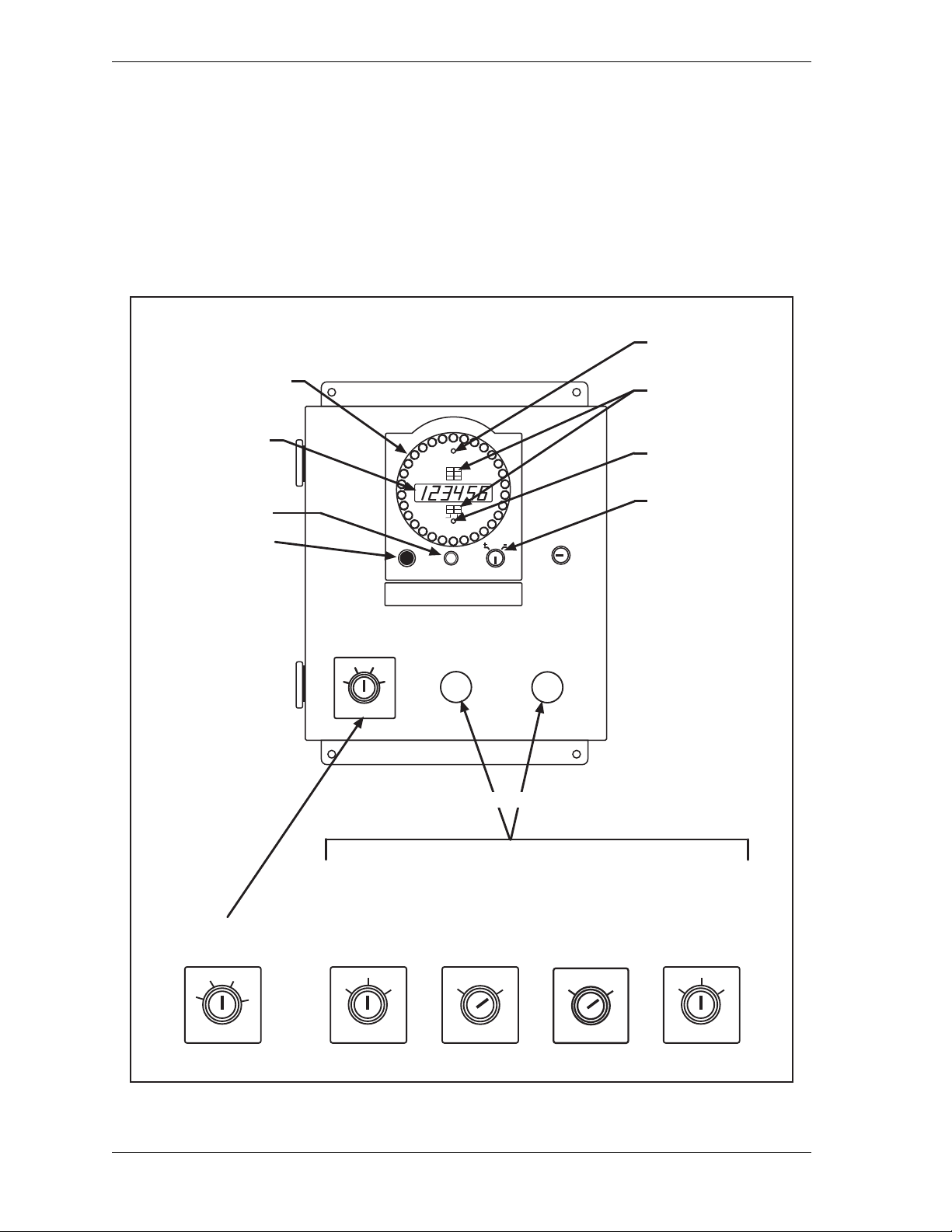
The WPC 2000 control enclosure (see Figure 1-1, page 1-2) can be ordered with the display
and controls mounted on the front (center mount) or on the left (left mount) or right side (right
mount). Up to three of the following selector key switches can be mounted in the enclosure:
• Stroke Select (Standard)–Provides switch settings for selection of Inch, Single-stroke, or
Continuous operation or Inch or Single-stroke.
• Mode Select (Optional)–Provides switch settings for selection of One-hand, Two-hand, or
Foot operation. Optional One-hand/Two-hand/Foot firmware is required for use of Onehand and Foot settings.
Introduction 1-1
Page 19
1128500 WPC 2000 User Manual
STROKE SELECT
O
F
F
I
N
C
H
S
I
N
G
L
E
C
O
N
T
WPC SETTINGSRESET/SELECT
BRAKE WARNING
INTERRUPTED STROKE
TOP STOP ANGLE
AUTO CARRYUP
STOP TIME LIMIT
MICRO-INCH
STOPPING TIME
STOPPING ANGLE
90
° STOP TEST
COUNTER
COUNTER PRESET
ANGLE / SPM
Digital LED Display
Counter
Press Speed
Error Codes
Crank Angle
Crank-angle Clock
Reset/Select
Button
Indicator Segments
WPC Settings
Key Switch
Interrupted Stroke
LED
Brake Warning
LED
cam on angle
cam off angle
MUTE
WPC 2000
Wintriss® Clutch/Brake Control
Mute lamp
Key switch options
Stroke Select
Key Switch
STROKE SELECT
O
F
F
I
N
C
H
S
I
N
G
L
E
C
O
N
T
Mode Select
Key Switch
(optional)
MODE SELECT
1
H
A
N
D
2
H
A
N
D
F
O
O
T
Micro-Inch
Key Switch
(optional)
MICRO-INCH
O
F
F
O
N
Automatic
[Single Stroke
(External Trip)
or Continuous
On-demand]
Key Switch
(optional)
AUTOMATIC
O
F
F
O
N
OP STN
A
B
O
T
H
B
Operator
Station Select
Key Switch
(optional)
• Micro-inch (Optional)–Provides a switch setting for turning on the Micro-inch feature (see
Standard Features, page 1-6).
• Automatic (Optional)–Provides a switch setting for turning on the Automatic Single-
stroke (External Trip) or Continuous On-demand feature.
• Operator Station Select (Optional)–Provides switch settings for selection of Operator
Station A, Operator Station B, or both Operator Station A and B in dual Operator Station
configurations.
1-2 Introduction
Figure 1-1. WPC 2000 Control Enclosure and Display
Page 20
WPC 2000 User Manual 1128500
PRIOR ACT
switch
PALM TIME
lamp
MUTE
lamp
TOP STOP
switch
EMERGENCY STOP
switch
RUN / INCH
palm switches
RUN/
INCH
RUN/
INCH
PAL M
TIME
PRIOR
ACT
MUTE
TOP
STOP
WINTRISS
E
M
E
R
G
E
N
C
Y
S
T
O
P
Operator Station
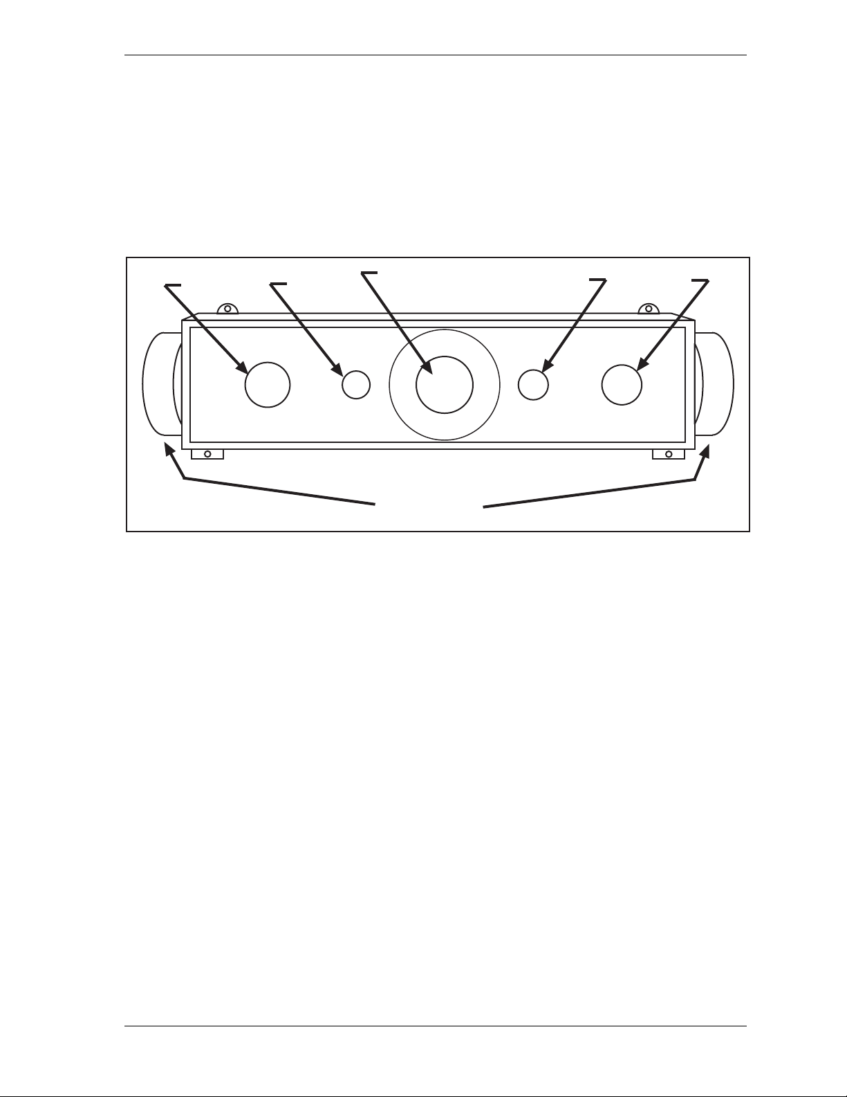
The Operator Station is normally the d evice used to run the press in all Stroke Selec t positions.
Wintriss provides operator stations with Run/Inch palm switches mounted on either the top or
sides (see
shows the switches and indicator lamps on an Operator Station with side-mounted Run/Inch
palm switches. Functions of these compon ents are shown below.
Installing Operator Station(s)
, page 2-12 for available configurations). Figure 1-2
Figure 1-2. Operator S tation Components (Side-mounted Run/I nch Palm Buttons)
• Run/Inch Palm Switches (2)–Initiate press action when both switches are pressed at the
same time (Two-hand mode) or when only the left switch is pressed (One-hand mode).
• Prior Act Lamp and Switch–An arming device that must be pressed in Continuous Two-
hand and Continuous Foot operating modes before a stroke can be initiated. When the
switch is pressed, the lamp illuminates for 8 seconds, indicating the interval within which
the operator must press the Run/Inch buttons or Foot Switch in order to stroke the press.
Also used in Automatic Single-stroke operation (see page 4-16).
• Emergency Stop Switch–Stops the press immediately when you push it. The switch is not
spring-loaded, so you must pull it back to its original position to clear the emergency stop
(F13) fault (see page 5-7).
• Top Stop Switch–Stops the press at the top of its stroke when pressed during Continuous
operation.
• Palm Time Lamp–Illuminates when one Run/Inch palm button is depressed, turning off
after the 1/2 second palm time (“synchronous” time in ANSI terminology) on a standalone
Operator Station or the 5 second concurrent time on multiple Operator Stations. The other
palm button on a standalone Op. Station or all pairs of buttons on multiple Operator
Stations must be pressed before the lamp turns off in order to initiate a stroke.
• Mute Lamp–Illuminates during muting of the light curtain on the upstroke. Requires
installation of a Shadow light curtain and optional light curtain muting firmware.
Introduction 1-3
Page 21

1128500 WPC 2000 User Manual
Other Components
Dual-monitored Safety Valve (DSV)
The DSV controls the flow of air to the press clutch and brake. Wintriss provides 3/4 in. and
1 in. Ross DM2 DSVs. See Installing a Dual Safety Valve, page 2-9 for further details.
System Air Pressure Switch
This switch monitors the system ai r pressure . See Install ing Air Pressur e Switches, page 2-11
for additional information.
Shadow Light Curtain
The Shadow light curtain is a presence-sensing device that places an infrared light field
between the point-of-operation and the operator. When an object, like the operator’s hand,
enters the sensing field and blocks a light beam, the light curtain detects the object and issues
an Emergency-stop command to the press.
The Shadow light curtain is required for point-of-operation guarding if WPC 2000 is used
with a Foot Switch or in One-hand operating mode. Multiple light curtains can be wired to a
WPC 2000. WPC 2000 tests up to two pairs of Shadow inputs every time that the press is
started and stopped. See Installing a Light Curtain, page 2-18 for more information.
WPC 2000 is designed to be used with a Shadow light curtain. If you order WPC 2000
without a light curtain, the control enclosure does not have a Mode Select switch, and the unit
operates only in Two-hand mode.
The light curtain is placed between the Operator Station and the die space. Shadow’s
mounting-bracket design allows plenty of room for adjustment.
WPC 2000 Display
The WPC 2000 display provides the following features (see Figure 1-1):
• Digital LED Display–A highly visible, six-digit readout which shows press speed (SPM),
crankshaft angle, stopping time, and other press parameters. The information displayed
depends on the current Stroke Select setting (see Control Enclosure, page 1-1) and the
indicator segment selected (see next item). The LED readout also displays WPC 2000 fault
codes and abbreviated text messages.
• Indicator Segments–Ten LED indicators which, when illuminated (i.e., selected), display
press information in the digital LED readout. To select a segment in the upper group of six
segments, press the Reset/Select button until that segment is illuminated. The segments in
the lower group of four segments can only be selected when WPC 2000 is in Inch mode.
When illuminated, indicator segments display press speed, crankshaft angle, 90° stop-time
test result, stopping time, stopping angle, stroke counter, counter preset, top-stop angle,
auto carry-up angle, stop-time limit, micro-inch ti me, and c am On/Of f a ngles. See Viewing
and Setting Press Parameters, page 3-1.
1-4 Introduction
Page 22

WPC 2000 User Manual 1128500
• Crank-angle clock–A circular series of LEDs that displays dynamically the approximate
angular position of the crankshaft whether the press is running or idle. Each LED in the
clock represents approximately 11°.
• Reset/Select Button–Allows you to select indicator segments for display (see previous
item) and clear, or reset, fault conditions that appear on the digital LED display.
• WPC Settings Key Switch–When turned to “+” (i.e., counterclockwise), increments the
value displayed in the LED readout; when turned to “–” (i.e., clockwise), decrements the
displayed value.
• Brake Warning LED–An amber LED that flashes when the stopping time of the press
increases to within 10 milliseconds of the preset Stop-time Limit, alerting the operator that
it is time to schedule maintenance on the brake. The LED can be turned off only by
powering down WPC 2000, then powering the unit back up.
• Interrupted Stroke LED–A red LED that flashes when an Interrupted Stroke (see
Standard Features, below) occurs.
• Mute Lamp–A lamp that illuminates when the light curtain is muted during the upstroke.
Requires installation of a light curtain and optional light curtain firmware.
Standard Features
WPC 2000 provides the following standard features:
• Interrupted Stroke–An Interrupted Stroke occurs when the press is Emergency-stopped
before the completion of a stroke by either the operator or an automatic device for
personnel or equipment protection. When this happens, the Interrupted Stroke LED
flashes, and WPC 2000 switches to “T wo-hand M aintained Single-stroke” mode. (If WPC
2000 was set to Inch mode, the press stays in Inch mode.) To clear the Interrupted Stroke,
the operator pushes both Run/Inch buttons simultaneously and holds them until the press
reaches the top of the stroke. At this point, the Interrupted Stroke LED turns off, and WPC
2000 automatically reverts to the original operating mode.
• Customized Status Codes–WPC 2000 provides nine user input s t hat allow you to moni tor
auxiliary press functions, such as lubrication systems. When one of these functions issues a
Stop command, a unique status code is displayed on the digital LED readout to identify
why the press stopped. Two of the inputs are cross-checked pairs, which you can use for
safety interlocks. If you install the optional Option 1 board, you can connect up to 20
additional non-control-reliable inputs and up to 4 additional control-reliable, cross-checked
input pairs (see Appendix C).
• Brake Monitor–WPC 2000’s Top-stop brake monitor checks the press’s braking
performance every time a Top-stop command is initiated or when the press completes a
stroke at Top-stop. When the press’s stopping time is within ten milliseconds of the preset
Stop-time Limit, the Brake Warning LED flashes. When the stopping time exceeds the
Stop-time Limit, WPC 2000 issues a Stop command to the press and prevents the press
from being restarted until the brake has been serviced.
• 90° Stop-Time Test–This standard feature is required in order to set the correct safety
distance for personnel-guarding devices including light curtains, two-hand controls, and
type-B movable barriers. The test is performed at 90°, the press’s most critical stopping
Introduction 1-5
Page 23

1128500 WPC 2000 User Manual
point, with the press running in Continuous and the heaviest die installed. The results of
the test provide the stopping time (Ts) value specified in both OSHA 1910.217 and ANSI
B11.1-2009 (see Appendix A).
• Counter and Counter Preset–The counter maintains a cumulative total of the number of
strokes made by the press. When the count total reaches the value set on the Counter Preset
indicator segment (see page 4-6), WPC 2000 stops the press. The counter is reset to “1”
with the Reset/Select button. The counter preset feature is useful for batch sizing or
periodic QC checks.
• Micro-inch–A feature that allows you to set the amount of time that the Dual Safety Valve
is open in Inch mode when you push the Run/Inch palm buttons. Normally, in Inch the
DSV is open for only as long as the Run/Inch buttons are depressed. The Micro-inch
setting specifies the length of time the DSV is open regardless of how long the Run/Inch
buttons are held. Allowing finer adjustments than are possible in Inch, Micro-inch is
designed to facilitate setup on high-speed or short-stroke presses. Requires installation of
optional Micro-inch selector switch (see page 1-2).
• Error Codes–WPC 2000 displays a two-digit code preceded by the letter “E,” “F,” or “H
whenever the press is stopped because of a fault. The two-digit code identifies the specific
problem that caused the fault. The initial letter indicates how the fault should be reset, and
in the case of F and H errors, specifies the processor (A or B) that detected the problem.
Underlying causes and remedies for each fault code are provided in Chapter 5.
• Lockout–Selected error codes that are associated with serious error conditions generate the
lockout message “Loc,” which displays in the digital LED readout when the error has been
reset. The lockout function provides an added safety feature to WPC 2000, forcing the
operator to perform two different Reset operations. The “Loc” message is cleared by
turning the Stroke Select key switch to “OFF,” then to “INCH.”
Optional Features
WPC 2000 can be ordered with any of the following optional features:
• Counterbalance Air Pressure Switch–Operating identically to the clutch air pressure
switch, this switch is used with the counterbalance air supply on presses equipped with
counterbalances, as required by OSHA regulations.
• Four-channel Programmable Cam Switch–Provides cam timings for feed, pilot release,
air blow-off, lubricator, or other non-safety press equipment.
• One-hand Control–A low-force switch that can be used with WPC 2000 running One-
hand/Two-hand/Foot firmware and equipped with a Shadow light curtain guarding the
point of operation. The One-hand Control switch can be mounted on or near the press,
allowing the operator to press the switch as part of his normal hand motion after loading a
part.
• Foot Switch–A device that frees the operator’s hands for increased, fully-guarded
protection and productivity. One-hand/Two-hand/Foot firmware is required, and a Shadow
light curtain must be installed.
• Bar Mode Control–Allows operators and setup personnel to bar the press by hand for die
setting and adjustment. Recommended for smaller-capacity presses of 65 tons or less.
1-6 Introduction
Page 24

WPC 2000 User Manual 1128500
DANGER
!
NOTICE
• Automatic Single-stroke (External Trip)–Allows feed equipment to signal WPC 2000 to
initiate a stroke upon completion of a feed. This option is useful in applications where the
feed must be completed before the press can be stroked.
• Automatic Continuous On-demand–Allows an external device to signal WPC 2000 to
start the press in Continuous mode and maintain operation in Continuous.
• Auto Compensated Top Stop (ACTS)–A feature that automatically adjusts the Top-stop
“On” Angle to an earlier point in the stroke to compensate for increases in press speed.
ACTS is designed specifically for variable-speed presses. See Switch 4 – Enabling Auto
Compensated Top Stop (ACTS), page 3-28 for additional information about this feature.
• Multiple Operator Stations–Two Operator Stations can be connected directly to WPC
2000. If you wish to install more than two Op. Stations, contact Wintriss Tech. Support
(see Installing Multiple Operator Stations, page 2-17).
HAZARDS EXPOSED BY NON-WORKING OPERATOR STATION
• Safeguard the point of operation exposed by the non-working Operator Station when
using multiple Operator Stations. The exposed area near a disabled Operator Station
must be properly guarded.
• Ensure that guarding is properly installed to prevent access to the machine over, under
or around any guarding device.
Failure to comply with these instructions will result in death or serious injury.
Use light curtains in addition to multiple operator stations for best personnel safeguarding.
• Display Configuration Options–WPC 2000 is available without an enclosure.
Installation instructions for panel mount and display board kit options are provided
beginning on page 2-51.
• Auxiliary E-Stop Output Relay Board–Allows up to three auxiliary devices such as a
feed or transfer to be stopped or prevented from starting when an E-stop button is pressed,
a light curtain is interrupted, or a cross-checked input is open.
If your WPC 2000 has Shadow light curtain muting firmware, you can prevent the
auxiliary E-stop relays from issuing a Stop command if the light curtain is interrupted
during the muted portion of the stroke by setting option switch 2 on switch block S102 on
the WPC 2000 Main Processor board (see page 3-32). The auxiliary E-stop muting
function is necessary in applications where parts must be ejected through a light curtain.
Auxiliary relay muting does not prevent the auxiliary relays from issuing a Stop command
when an E-stop button is pressed or a cross-checked input is open.
Layout of the Auxiliary E-Stop Output Relay board is shown in Figure 2-12, page 2-23 or
Figure 2-13, page 2-24. Wiring connections are shown in Table 2-19, page 2-63.
Introduction 1-7
Page 25

1128500 WPC 2000 User Manual
Specifications
WPC 2000 specifications are shown in Table 1-1.
Table 1-1. WPC 2000 Specifications
Control Enclosure: 14.00 x 19.62 x 7.00 in. (355.6 x 498.3 x 177.8 mm), NEMA 12,
shock-mounted.
Panel Mount: 7.50 x 10.00 in. (190.5 x 254.0 mm)
Standard items include 6-digit LED display, display indicators, crank-angle
clock, Interrupted Stroke and Brake Warning LEDs, Reset/Select button,
Mute lamp, and Settings key switch. Enclosure also provides Stroke Select
key switch and holes for two optional key switches.
Equipment
Available from
Wintriss Controls
Wintriss AC Power
Supply (Included)
Power Requirements
if not Using Wintriss
AC Power Supply
Operating
Temperature
Inputs Resolver
Resolver
0.75 in. (19 mm) keyed shaft. Rated shaft loading: 200 lb axial, 200 lb
radial.
Operator Station
NEMA 12. Includes two palm buttons, T op-stop, Emergency-stop, and Prior
Act buttons, and palm time and mute lamps. Pre-wired; unwired version
also available.
Dual Safety Valve (DSV)
Available in 0.75 in. (19 mm) or 1 in. (25 mm) Ross DM2 models.
Air Pressure Switch
12-150 PSI. Monitors clutch air supply pressure.
Input: 100-240 ± 10% Vac (universal switching), 75 VA, 50/60 Hz.
Output: 24 ± 1% Vdc, 200 mA maximum for customer use including
auxiliary outputs.
24 ± 5% Vdc, 2 A.
Must be certified to CSA C22.2 No. 234 Standard.
32° to 122° F (0° to 50° C).
Overrun limit switch
Two operator stations
DSV monitor
Air pressure switch
1-8 Introduction
Page 26

WPC 2000 User Manual 1128500
Table 1-1. WPC 2000 Specifications (Cont)
Additional Inputs Motor
Forward and reverse contacts
Shadow Light Curtains (2)
Checks proper functioning at every stroke initiation and stop.
Customized Status Codes
Four for E-stop
Three for Top-stop
One cross-checked pair for E-stop
One cross-checked pair for E-stop/Lockout
Outputs DSV
Two monitored relays, rated 4 A @ 120 Vac, for E-stopping and
To p-sto ppi ng pres s.
Lockout
One monitored relay, rated 4 A @ 120 Vac, for de-energizing motor and
other devices under critical conditions.
Auxiliary Stop Output
Provides a signal to stop auxiliary equipment during an interrupted stroke.
Optional Auxiliary E-Stop Output Relays
Two monitored relays, rated 4 A @ 120 Vac, for up to three auxiliary
devices (e.g., feed, transfer , etc.), which can be stopped or prevented from
starti ng if any E- stop bu tton is d epres sed, an y ligh t curt ain is interr upte d, or
any cross-checked inputs are open.
Speed 7-500 SPM; 500-2000 SPM optional.
Displays Six-digit LED. Displays press speed, crankshaft angle, presettable counter,
90
° stop-time test result, stopping time, stopping angle, top-stop angle,
auto carry-up angle, stop time limit, and micro-inch as well as cam on/off
angles and status/error codes. Also displays press control timings, which
are secured with keylock and/or internal press option switch. Crank-angle
clock.
LED indicators for Interrupted Stroke and Brake Warning.
Diagnostic LEDs on Main Processor board for power and for all inputs,
including buttons and switches.
Presettable Counter
Counts number of strokes; can be used to stop the press for batch sizing or
QC checks. Includes 6-digit counter on front panel of WPC 2000.
Introduction 1-9
Page 27

1128500 WPC 2000 User Manual
Table 1-1. WPC 2000 Specifications (Cont)
Options Shadow V, Shadow VI, Shadow VII, or Shadow 8 Light Curtain
Heights from 6 to 60 in., scanning ranges from 23’ to 65’. Refer to Shadow
literature for more information.
Firmware
Muting for Shadow light curtain on the upstroke. Two-hand only. Onehand*, two-hand or foot operation*. Automatic Single-stroke (External Trip).
Continuous On-demand. Auto compensated top-stop (ACTS). High Speed
(>500 SPM).
Selector Switches
Mode (One-hand*, two-hand, or foot operation*). Micro-inch on/off.
Automatic (single-str oke or continuous on-demand) on/off to slave the
press to an external device. Operator station select for either of two
operator stations or both operator stations.
4-Channel Programmable Cam
Enclosure: 5.41 x 7.38 x 3.48 in. (137. 4 x 187. 5 x 88.4 m m), sho ck-mounted
Relay: SPDT 0-3A resistive at 240V (standard)
DC Solid State: SPST 2A at 5-60 Vdc optional
AC Solid State: SPST 1A at 70-250 Vac (optional)
Foot Switch
Safety switch for foot actuation* (1-hand/2-hand/foot firmware required).
One-hand Control
Control for one-hand actuation* (1-hand/2-hand/foot firmware required).
Counterbalance Air Pressure Switch
12-150 PSI. Monitors counterbalance air supply (uses one custom input).
Bar Mode Control
Allows manual turning of crankshaft.
Motor Control and Custom Packages
Refer to Press Control/Motor Starter literature, and/or contact your Wintriss
representative or factory for more details.
Option 1 User Inputs
Provides 20 additional non-control-reliable inputs and 4 additional controlreliable, cross-checked input pairs for customized status codes.
Eight inputs are E-stop
Ten inputs are Top-stop
Two inputs are E-stop/Lockout
Two cross-checked pairs are E-stop
Two cross-checked pairs are E-stop/Lockout
* Shadow light curtain required
1-10 Introduction
Page 28

Chapter 2. Inst allation
DANGER
!
DANGER
!
IMPROPER INSTALLATION, USE OR MAINTENANCE
• Follow all procedures in this manual. Perform only the tests and repairs listed in this manual.
Use only factory-supplied replacement parts.
• Ensure that WPC 2000 clutch/brake control is installed, tested and repaired by qualified
personnel.
• Wire, install and maintain WPC 2000 clutch/brake control in accordance with the applicable
safety standards. Carry out all inspection procedures in OSHA 1910.217.
• Wire and install all equipment in accordance with the requirements of OSHA 1910.147 Control
of Hazardous Energy (Lockout/Tagout).
• Install and maintain your machine guarding system according to OSHA standard 1910.217,
ANSI B11.1, ANSI B11.19 and any other regulations and standards that apply. Ensure that
guarding is properly installed to prevent access to the machine over, under or around any
guarding device.
• Perform the checkout sequence after installation and after any modification or repair of the WPC
2000 clutch/brake control.
• Lockout/Tagout the press during all installation, modification, repair or maintenance procedures.
• Ensure that supervisors, die-setters, maintenance persons, machine operators, foremen, and
any others responsible for operation of the machinery have read and understood all instructions
for use of the WPC 2000 clutch/brake control.
• Disconnect the “Continuous” mode position of your stroke selector switch and cover the “CONT”
label on your control if the press is not properly guarded for use in Continuous mode.
Failure to comply with these instructions will result in death or serious injury.
FAULTY INSTALLATION
• Ensure that wiring is correct.
• Use only safety-certified components for safety functions, including interlock switches used in
safety applications.
• Install guarding to prevent access to hazardous areas. Prevent access to hazardous areas
over, under, or around any guarding devices.
• Ensure that there is one active Operator Station for each operator if you are using Two-hand
mode.
Failure to comply with these instructions will result in death or serious injury.
Installation 2-1
Page 29

1128500 WPC 2000 User Manual
DANGER
!
NOTICE
NOTICE
NOTICE
NOTICE
ELECTRIC SHOCK OR HAZARDOUS ENERGY
• Disconnect main power before installation.
• Remove all power to the press, press control, and other equipment used with the press.
• Remove all fuses and “tag out” per OSHA 1910.147 Control of Hazardous Energy (Lockout/
Tagout).
• Ensure that installation is performed by qualified personnel.
• Complete all installation procedures before connecting to the AC power source.
Failure to comply with these instructions will result in death or serious injury.
When you have completed installation procedures, perform the tests in the Installation Verification
section, page 2-58 to ensure that WPC 2000 is installed correctly and working properly before
proceeding to Chapter 3.
ALL SIGNAL GROUNDS MUST BE CONNECTED THROUGH MAIN PROCESSOR BOARD
Connect all signal grounds through pins on the WPC 2000 Main Processor board.
READ INSTALLATION INSTRUCTIONS BEFORE STARTING INSTALLATION
If you install WPC 2000 yourself, read this installation chapter carefully and plan how you are
going to proceed before you start drilling holes, running conduit, or cutting wires. Make sure you
are familiar with the WPC 2000 display (see page 1-2). If you encounter problems during
installation, contact Wintriss Tech. Support.
PRESS MUST BE AT TDC
Before starting installation, make sure that the die has been removed from the press and the press
ram has been moved to top dead center (TDC). The press must be at TDC when you make final
adjustments for the resolver. The TDC setting should be 0° ±2°. Use a dial indicator on the face
of the ram, if necessary, to ensure that the ram is positioned correctly.
2-2 Installation
Page 30

WPC 2000 User Manual 1128500
Installation Guidelines
Observe the following guidelines when installing WPC 2000, referring to Figure 2-1,
page 2-4 when necessary.
• For AC wiring, use 16 AWG wire (14 AWG if required by local codes) with a minimum
75° C temperature rating. For other wiring, use 18 AWG with 600 V insulation.
• All signal grounds must run through the WPC 2000 Main Processor board. Use chassis
ground only for terminating cable shields.
• Run flexible, liquid-tight conduit for high voltage lines (120V power, relay circuits) to the
upper left knockout on the WPC 2000 enclosure.
• Never run wires for 120V and for lower voltages (such as 24V or 60V) inside the same
conduit. For example, the Operator Station cables should not share the same conduit with
120 Vac wiring. However, power and logic wiring for the light curtain or Dual Safety
Valve (DSV) can be run in the same conduit.
• Provide a dedicated 120V power circuit from the press control transformer to the WPC
2000 input power connection. Do not power any relays or solenoids from this circuit or the
auxiliary power terminals on WPC 2000. Doing so may cause erratic press shutdowns due
to electrical noise.
• Run one or two low-voltage conduits for the resolver wires to the knockouts on the bottom
of the WPC 2000 enclosure.
• Because WPC 2000 is rated NEMA 12 (protected against dust and oil), you must use
conduit of the same rating and make proper connections to ensure NEMA 12 protection.
• Make sure the WPC 2000 is properly grounded.
• All relays and solenoids controlled by WPC 2000 must be suppressed. Suppressors should
be installed across the load and as close to the load as possible. Never install a suppressor
across the relay contacts. The suppressors tend to fail shorted. In some cases, suppressors
are required in the Top-stop and Emergency-stop circuits. Additional suppressors (part
number 2238801) can be obtained from Wintriss.
Installation 2-3
Page 31
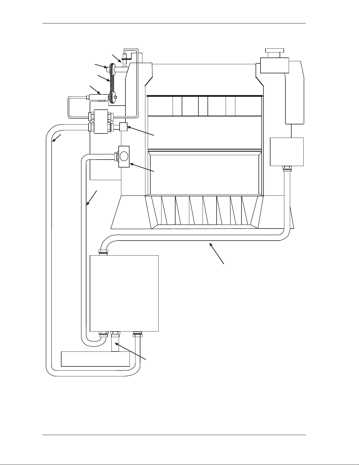
1128500 WPC 2000 User Manual
Overrun limit switch
Timing chain
Resolver
Air pressure switch
Dual Safety Valve
(DSV)
DSV wiring
Resolver,
overrun limit
switch and
air pressure
switch wiring
Operator
Station
wiring
120 Vac high voltage
wiring (from Customer
Control Transformer)
Wintriss
Clutch/brake
Control
Operator Station
Motor
Control
Crankshaft
Figure 2-1. WPC 2000 Wiring Overview
2-4 Installation
Page 32
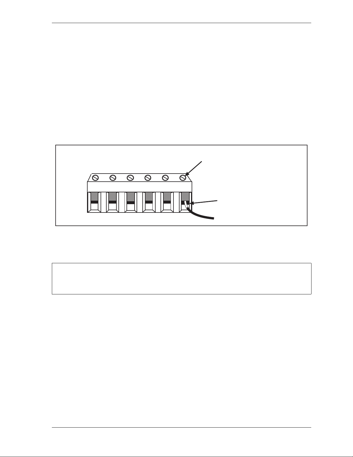
WPC 2000 User Manual 1128500
Insert wire here
Tighten screw to clamp
wire in terminal
NOTICE
Connecting Wires to Terminal Block Connectors
When connecting wires to terminal block connectors, follow these steps:
1. Find the correct terminal and loosen the screw over it by turning the screw
counterclockwise (see Figure 2-2).
2. Strip the correct wire for this terminal 1/4 in. (6.4 mm) from the end.
3. Insert bare wire into the terminal 90% of the way.
4. Tighten the screw. The metal tooth inside the terminal will clamp down on the bare wire
for a tight connection. Make sure that the metal tooth is clamped down on the bare part of
the wire, not on the insulation.
Figure 2-2. Correct Way to Attach Wires to Terminal Block Connectors
Terminating Cable Shields
TERMINATE BOTH ENDS OF SHIELD
Be sure to terminate the cable shield at both ends where possible.
Perform the following steps to terminate shielded cables to the ground studs located inside the
WPC 2000 enclosure near the cable’s point of entry, referring to Figure 2-3, page 2-6.
1. Strip the cable jacket as far as the end of the conduit fitting.
2. Cut the drain wire to a length that can wrap at least once around the nearest ground stud.
Loosen the nut, wrap the drain wire clockwise around the stud, and tighten the nut.
3. Connect the rest of the wires in the cable to the terminal block as appropriate.
Installation 2-5
Page 33
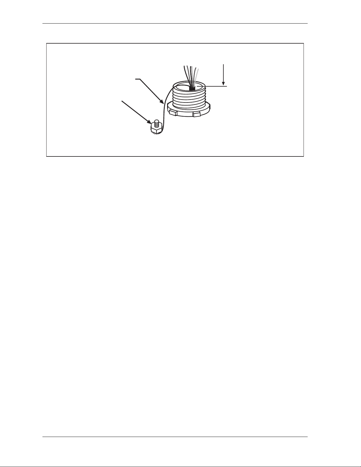
1128500 WPC 2000 User Manual
Secure drain wire
under nut on
ground stud
Drain wire
Strip cable jacket
as far as end of
conduit fitting
Figure 2-3. Cable Shield Termination
Mounting the Control Enclosure
Mount the control enclosure (see Figure 2-4, page 2-7 for mounting dimensions) so that it is
convenient to the operator. An optimal location is one that allows the operator to read the
digital display and reach the key switches while standing at the front of the press. The best
location will vary depending on the type of enclosure you have ordered–center mount, left
mount, or right mount.
The enclosure does not have to be mounted to the press but can be installed on a free-standing
pedestal, pendant, or column.
For easy access to the interior of the enclosure, make sure that there is enough room to open
the control enclosure door at least 120°.
Plastic cable ties and self-sticking cable clamps are provided in the accessory parts bag. Use
them to organize the cables and wiring inside the control enclosure.
Wiring the Control Enclosure
WPC 2000 requires the following electrical components:
• Motor forward auxiliary contact (24V)
• Slide adjust monitor circuit (24V)
• Motor stop circuit (110V), if applicable
• Motor reverse auxiliary contact (24V), if applicable
Power to WPC 2000 should be provided by a step-down control transformer capable of
handling 75 VA at 115 Vac ± 10%.
Most of the original controls on the press will be replaced during rewiring except the
disconnect, motor starter, and control transformer. Make sure to rewire so that the motor
starter operates properly.
2-6 Installation
Page 34
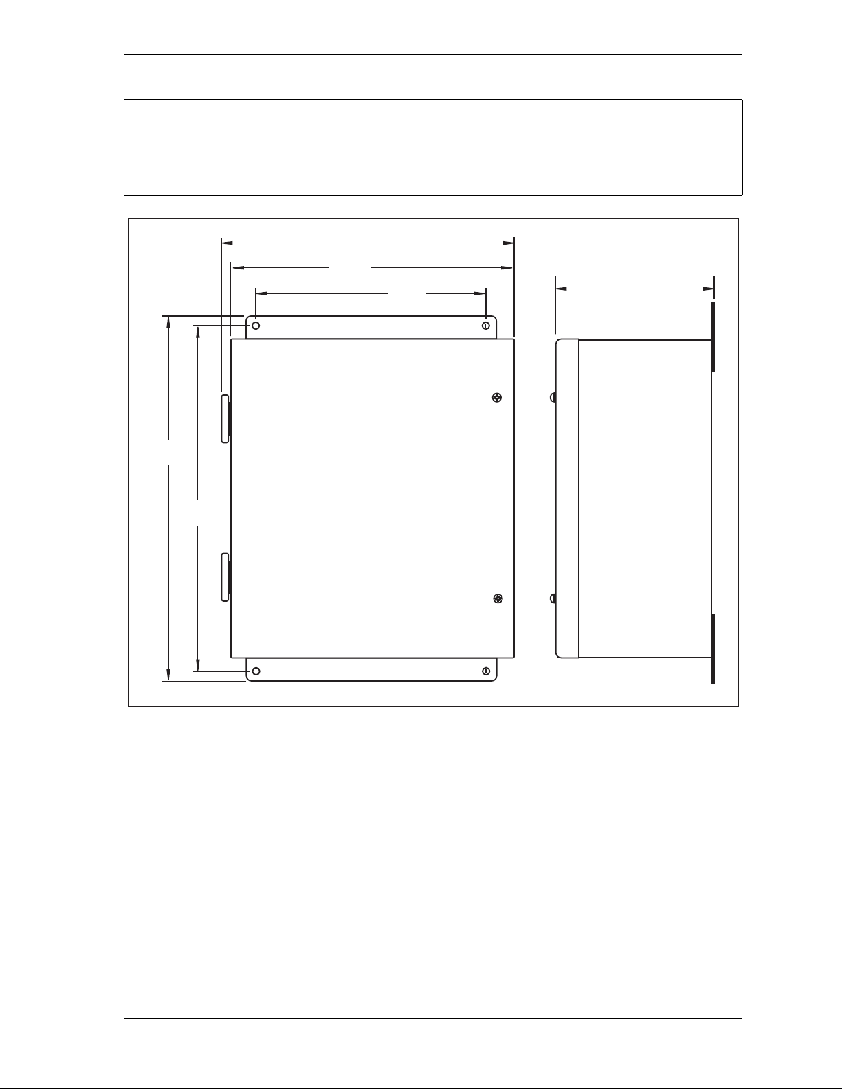
WPC 2000 User Manual 1128500
NOTICE
12.00
(304.8)
14.68
(372.8)
17.62
(447.6)
16.88
(428.8)
Note: Allow sufficient clearance
for opening door
7.27
(184.5)
14.28
(362.7)
Dimensions: inches
(mm)
NON-ENCLOSURE INSTALLATION
See Installing WPC 2000 without Enclosure, page 2-51 for installation instructions if you are
installing WPC 2000 in your own enclosure or console.
Figure 2-4. WPC 2000 Enclosure: Mounting Dimensions
Slide Adjust Considerat i ons
If your press has a motorized slide adjustment for the ram, you must prevent slide adjustment
while the press is running. Connect spare contacts on the slide adjustment swit ches (i.e., Slide
Adjustment “On” or Slide Adjustment “Up”/“Down” switch) to the WPC 2000 Emergencystop circuit or a user interlock to stop the press as soon as the ram adjust switches on. For help
in determining how to connect this wiring, call Wintriss Tech. Support.
Installation 2-7
Page 35
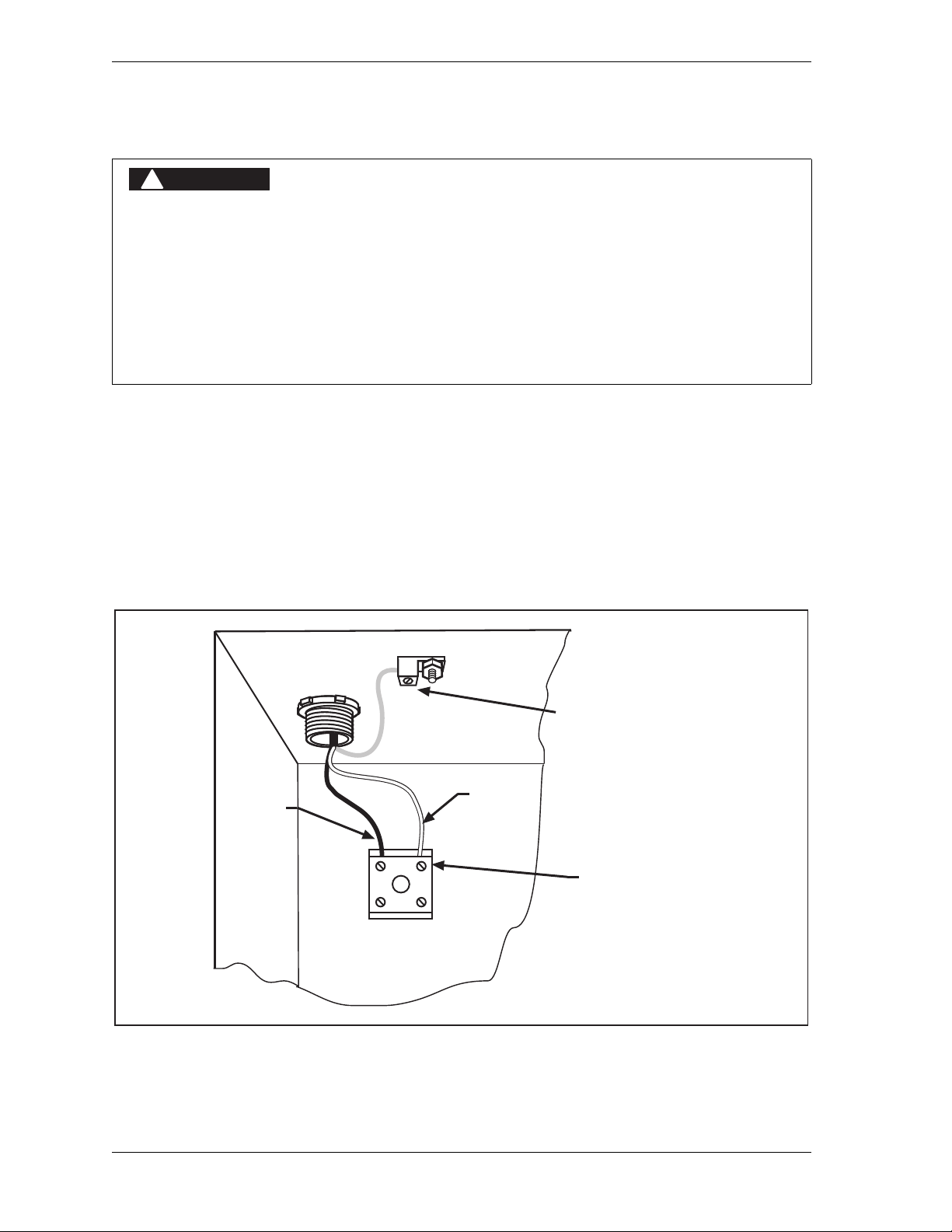
1128500 WPC 2000 User Manual
DANGER
!
LINE
NEUT
Connect ground wire
to set screw ground
terminal
Neutral
Line
Top left corner
inside enclosure
Input Power
Terminal block
Connecting AC Wiring
ELECTRIC SHOCK OR HAZARDOUS ENERGY
• Disconnect main power before installation.
• Remove all power to the press, press control, and other equipment used with the press.
• Remove all fuses and “tag out” per OSHA 1910.147 Control of Hazardous Energy (Lockout/
Tagout).
• Ensure that installation is performed by qualified personnel.
• Complete all installation procedures before connecting to the AC power source.
Failure to comply with these instructions will result in death or serious injury.
All wires can be run through flexible, liquid-tight conduit to the control as long as all circuits
are 115V. If your Top-stop circuits and Emergency-stop circuits are low voltage (for
example, 24V), run two conduits–one for 115V wires and one for 24V wires. Be sure to
number all wires so they are consistent with the electrical prints for your press.
Bring the wiring connections for AC power to a convenient point so that you can connect
them to the power terminal block at the top left of the enclosure (see Figure 2-5). No. 16 wire
(No. 14, if local codes require it) is recommended for these circuits with a minimum 75° C
temperature rating.
Figure 2-5. AC Input Wiring Connections
2-8 Installation
Page 36

WPC 2000 User Manual 1128500
NOTICE
DANGER
!
DANGER
!
WPC 2000 AUTOMATICALLY ADJUSTS TO 115 OR 230 VOLT INPUT POWER
You do not need to use a switch or other device to set the level of input power.
To make AC power wiring connections, perform the following steps:
1. Locate the power supply input terminal block on the back wall at the top left of the
enclosure, as shown in Figure 2-5.
2. Determine how you will bring wiring from your 115 or 230 Vac power source to the
enclosure. For 115 Vac, you need three wires—high (black), neutral (white) and ground
(green). For 230 Vac, wires are black and red, with green or green-yellow for ground.
3. Run the power wires to the enclosure through flexible, liquid-tight conduit. Because WPC
2000 is rated NEMA 12 (protected against dust and oil), you must use conduit of the same
rating and make proper connections to ensure NEMA 12 protection.
4. Connect the ground wire to the set screw terminal on the roof of the enclosure, referring to
Figure 2-5 and to Figure 13 (Ross Serpar DSV), Figure 14 (Herion DSV), or Figure 17
(Ross DM2 DSV) at the back of the manual.
5. Connect the power wires.
For 115 Vac power, connect the black wire to the LINE terminal and the white wire to
NEUT.
For 230 Vac, connect the black wire to the LINE terminal and the red wire to NEUT.
Strip the wire 1/4 in. from the end. Loosen the screw in the input power terminal block,
insert the stripped portion of the wire, and tighten the screw.
6. Double-check connections.
7. Make all necessary conduit connections to ensure NEMA 12 protection.
Inst alling a Dual Safety Valve
USER-SUPPLIED DUAL SAFETY VALVE NOT SUITABLE FOR SAFETY USE
Ensure that your dual safety valve meets the applicable safety standards. Contact the valve
manufacturer for information.
Failure to comply with these instructions will result in death or serious injury.
INSTALL DSV CLOSE TO CLUTCH/BRAKE ASSEMBLY TO REDUCE STOPPING TIME
Install the dual safety valve as close as possible to the clutch/brake assembly. Any excess piping
between the valve and the clutch/brake assembly increases the Stopping Time of the press.
Failure to comply with these instructions will result in death or serious injury.
Installation 2-9
Page 37

1128500 WPC 2000 User Manual
WARNING
!
NOTICE
NOTICE
DSV MUFFLER CLOGGING OR LOOSENING
• Clean the DSV muffler periodically. A clogged muffler can degrade Stopping Time.
• Tighten the muffler securely to the valve body. Periodically check to make sure the muffler is
securely installed. Vibration may cause it to loosen and fall. To tighten the muffler, secure the
valve body, hold the muffler with both hands and turn clockwise as tightly as possible without
stripping the threads.
Failure to comply with these instructions could result in death or serious injury.
ALL SIGNAL GROUNDS MUST BE CONNECTED THROUGH MAIN PROCESSOR BOARD
Connect all signal grounds through pins on the WPC 2000 Main Processor board.
If you have ordered a Ross or Herion DSV with your WPC 2000, refer to the appropriate
wiring diagram at the end of this manual and to the documentation that came with your valve
to install the DSV. Note the following requirements:
• Ross DM2
To wire the Ross DM2 DSV, refer to figures 6 and 17 at the back of the manual.
The Reset circuit requires that a diode be installed across the coil in the solenoid to provide
noise suppression (see Figure 17). This wiring has already been done for you in the
Hirschmann connector for the 24 Vdc Reset solenoid, which is provided along with two
Hirschmann connectors for the 120 Vac valve solenoids in the Ross DM2 kit.
MAKE SURE TO INSTALL NOISE SUPPRESSION DEVICES
Noise suppression devices (Pactrons) are provided in the WPC Installation Kit. Be sure to
install them across the two Hirschmann connectors for the 120 Vac valve solenoids as
shown in Figure 17.
The Reset solenoid connector comes in two styles. One has a black shell with an electrical
circuit including a diode symbol ( ) printed on it, the other a transparent shell with a red
LED indicator visible inside. You install this connector on the Reset solenoid at one end of
the DSV. The Reset solenoid connector is the only connector at this end of the DSV. The
other two connectors are installed on the two valve solenoids at the other end of the DSV,
which has three connectors altogether, including one for the DSV monitor that is already
installed. You wire the Reset solenoid and valve solenoid connectors to WPC 2000 as
shown in Figure 17.
2-10 Installation
Page 38

WPC 2000 User Manual 1128500
CAUTION
NOTICE
DO NOT WIRE RESET CIRCUIT TO 110 VAC
The Reset circuit works only on 24 Vdc. Do not wire the Reset circuit to 110 Vac.
Failure to comply with these instructions could result in property damage.
Note that the DM2 Reset circuit is wired to the OFF position on the WPC 2000 Stroke
Select switch (see Figure 6). To reset the Ross DM2 DSV after an F47 error (see
page 5-12), press Reset/Select, and turn the Stroke Select switch to OFF, then back to one
of the other operating modes (i.e., Inch, Single-stroke, or Continuous).
Make sure to install air supply lines that match the inlet port size of the DM2 DSV to
provide sufficient air to reset the unit in case of a fault (see page 5-20).
• Ross Serpar with EP Monitor
This Ross DSV requires a separate user-supplied reset switch. See Figure 14 at the end of
this manual. Also, all jumpers except those shown in the wiring diagram must be removed;
otherwise, the WPC 2000 Main Processor board may be damaged.
• Herion XSZ
Make sure that you wire the Herion DSV monitor between pin #20 and a +24 Vdc output.
See Figure 13 at the end of the manual.
Installing Air Pressure Switches
Your WPC 2000 requires switches to monitor clutch air pressure and counterbalance air
pressure if there is a counterbalance.
Both the clutch air and counterbalance air pressure switches are held closed when pressure is
applied above the setpoint limit.
Installi ng a Clutch Air Pressure Switch
Install and wire the clutch air pressure switch as follows:
1. Install a filter regulator and lubricator in-line before the clutch air pressure switch if they
are not already present.
2. Connect shop air to the clutch air pressure switch input port.
3. Run the cable through flexible, liquid-tight conduit, observing NEMA 12 requirements.
4. Wire the normally open terminals of the switch between pin #8 and ground (e.g., pin #54)
on the WPC 2000 Main Processor board, referring to Figure 2 at the end of the manual.
5. Set the clutch air pressure switch to 35 PSI, or the pressure recommended by the press
manufacturer.
Installation 2-11
Page 39

1128500 WPC 2000 User Manual
NOTICE
NOTICE
Installing a Counterbalance Air Pressure Switch
Install and wire a counterbalance air pressure switch as follows if there is a counterbalance:
1. Install a filter regulator and lubricator in-line before the counterbalance air pressure switch
if they are not already present.
2. Connect shop air to the counterbalance air pressure switch input port.
3. Run the cable through flexible, liquid-tight conduit, observing NEMA 12 requirements.
4. Wire the normally open terminals of the switch to pin # 83 (User Input 4) and ground (e.g.,
pin # 31), referring to Figure 2 at the end of the manual.
If pin #83 has already been assigned to other user-selected auxiliary equipment, then wire
the counterbalance switch contacts across a terminal on the WPC 2000 Main Processor
board that generates an E-stop when the connection to ground is broken. See Wiring
WPC 2000 User Inputs, page 2-28 for more information.
5. Set the counterbalance air pressure switch to the pressure recommended by the press
manufacturer, typically the pressure required for the smallest upper die you plan to use in
this press.
USING RAMPAC (SMARTPAC 1 OR 2) TO CONTROL C OUNT ERB ALANCE PRESSURE
If you use RamPAC to control the counterbalance pressure, set the WPC 2000
counterbalance pressure switch to the pressure required to balance the empty ram.
Installing Operator Station(s)
The Operator Station should be installed in a location from which the operator can
conveniently run the press. On most gap-frame (OBI or OBG) presses, this will be on the
front of the bolster. For straight-side presses, the Operator Station may be installed on the
press or on a pedestal.
The Operator Station should not be permanently mounted until you have calculated the
correct safety distance (see Calculating the Safety Distance, page 3-19) and performed the
applicable verification (see page 2-58) and checkout (see page 3-35) tests. When you have
finished wiring, you can place the Operator Station temporarily on the floor or on a cart.
If you are not installing a light curtain, and if you are planning to use the Operator Station as a
two-hand safety device, the Operator Station must be mounted at the correct safety distance
from the nearest pinch point on the press. This distance must be calculated based on the
Stopping Time of your press. See Calculating the Safety Distance, page 3-19 for details.
Mounting the Operator Station at the correct safety distance prevents an operator from leaving
the station and reaching the pinch point before the press stops.
2-12 Installation
Page 40
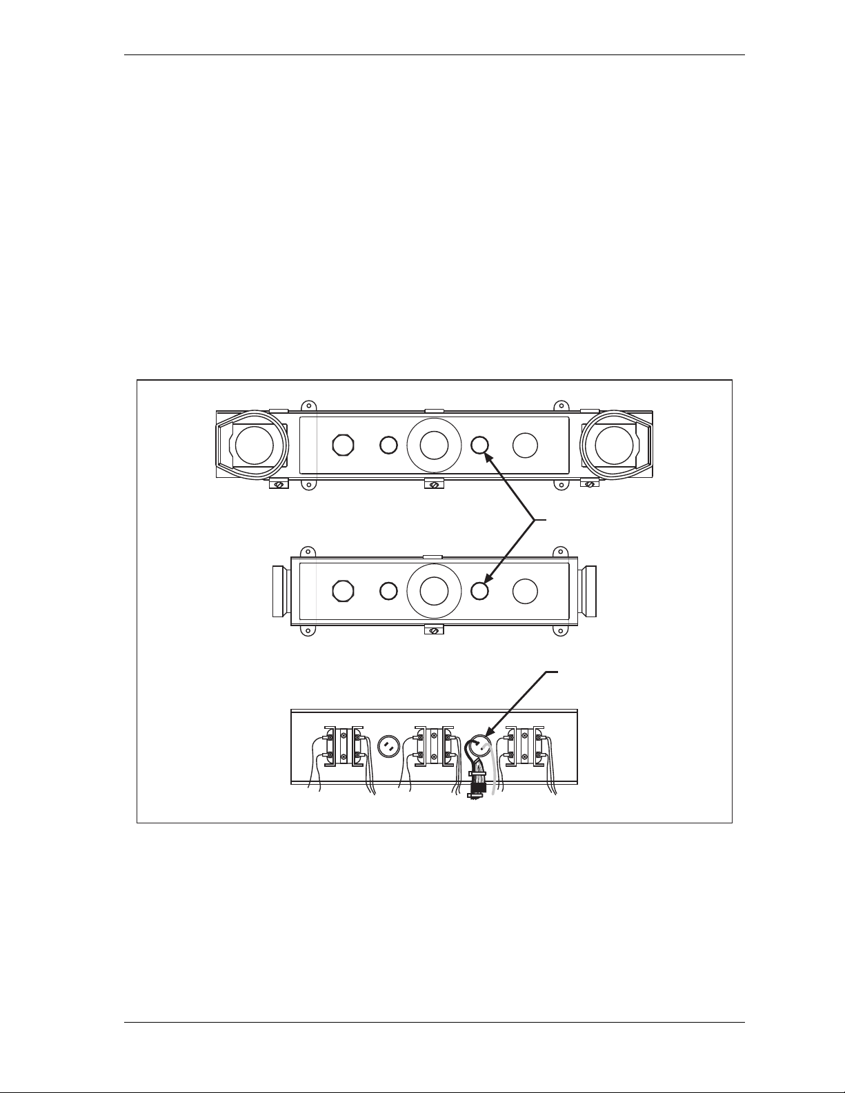
WPC 2000 User Manual 1128500
MUTE
PALM
TIME
PRIOR
ACT
INTRISS
W
TOP
STOP
R
U
N
/
I
N
C
H
R
U
N
/
I
N
C
H
MUTE
PALM
TIME
PRIOR
ACT
INTRISS
W
TOP
STOP
Mute Lamp
Pre-wired
Operator Stations
top view
Side-button
Operator Station
Cover, opened,
showing underside
of cover.
(Top-button station
is similar.)
Mute Lamp Connections
for WPC 2000
E
M
E
R
G
E
N
C
Y
S
T
O
P
E
M
E
R
G
E
N
C
Y
S
T
O
P
If you are installing a light curtain, the Operator Station must be placed outside the area
guarded by the light curtain. You do not need to calculate a specific safety distance for your
Operator Station since the light curtain now prevents access to the pinch point. You must not,
however, mount the Operator Station between the light curtain and the pinch point.
Wiring a Pre-wired Operator Station
Checking Pre-wired Operator Station Wiring
Before connecting your pre-wired Operator Station to WPC 2000, check the wiring to the
mute lamp inside the Operator Station and modify, if necessary, according to the instructions
below. Operator stations shipped as part of WPC 2000 systems should not need modification.
1. Find the mute lamp on the Operator Station, as shown in Figure 2-6.
2. Open the Operator Station, and locate the mute lamp connections on the underside of the
Figure 2-6. Pre-wired Operator Stations Showing Mute Lamp Connections
cover.
Installation 2-13
Page 41
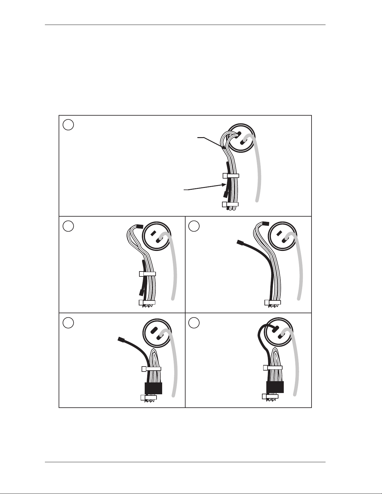
1128500 WPC 2000 User Manual
B
Free the black wire.
Disconnect the pair of
white-and-red wires.
C
Connect the black wire
where you just
disconnected the pair
of white-and-red wires.
Bend the white-and-red
wires back on themselves.
Ty-wrap them in place.
Insulate connector lug
with electrical tape.
D
E
Black wire with
connector lug,
not connected
to anything
Pair of white-and-red
wires connected to
one terminal
of the mute lamp
Examine the mute
lamp wiring as it
came from the factory.
NOTE:
Orientation of connections
may be different.
A
3. Determine whether you need to modify the mute lamp wiring:
• If your mute lamp wiring looks like panel “E” in Figure 2-7 (i.e., the black wire is
connected, the red-and-white wire not connected), the wiring is correct.
• If your mute lamp wiring looks like panel “A”, follow steps A through E in Figure 2-7
to disconnect the white-and-red wires and connect the black wire.
4. When the mute lamp wiring is correct, connect the Operator Station to WPC 2000.
2-14 Installation
Figure 2-7. Wiring S teps to Modify Operator Station for WPC 2000
Page 42
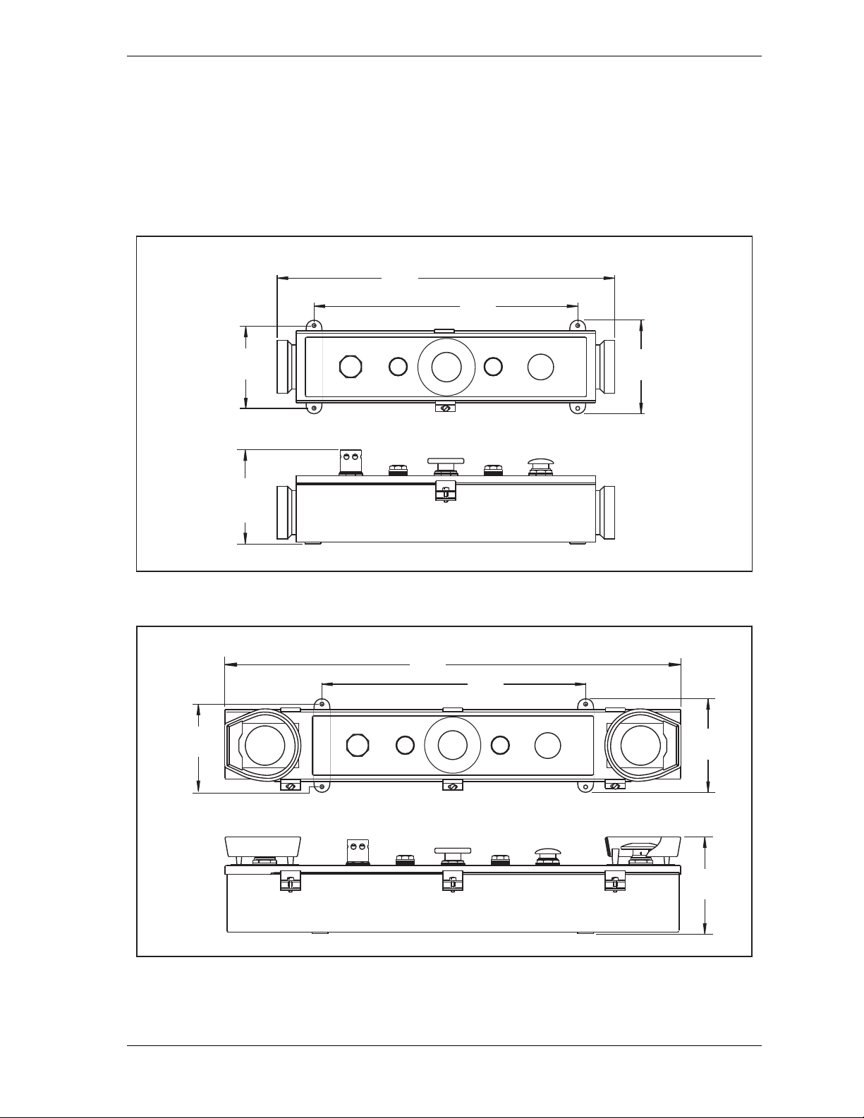
WPC 2000 User Manual 1128500
MUTE
PALM
TIME
PRIOR
ACT
INTRISS
W
TOP
STOP
5.8
(148)
REF
4.69
(119.1)
16.75
(425.5)
R
U
N
/
I
N
C
H
R
U
N
/
I
N
C
H
5.50
(139.7)
21.25
(539.8)
Dimensions:
inches
(mm)
E
M
E
R
G
E
N
C
Y
S
T
O
P
6.06
(154.0)
MUTE
PALM
TIME
PRIOR
ACT
INTRISS
W
TOP
STOP
16.75
(425.5)
28.75
(730.3)
5.50
(139.7)
4.69
(119.1)
E
M
E
R
G
E
N
C
Y
S
T
O
P
Dimensions:
inches
(mm)
Making Wiring Connections
To wire a pre-wired Operator Station, perform the following steps:
1. Punch a hole in the Operator Station enclosure for conduit or sealtight.
2. Connect the conduit or sealtight to the hole; then open the Operator Station box.
Figure 2-8. Pre-wired Operator Station with Side Run Buttons: Mounting Dimensions
Figure 2-9. Pre-wired Operator S tation with Top Run Buttons: Mounting Dimensions
Installation 2-15
Page 43
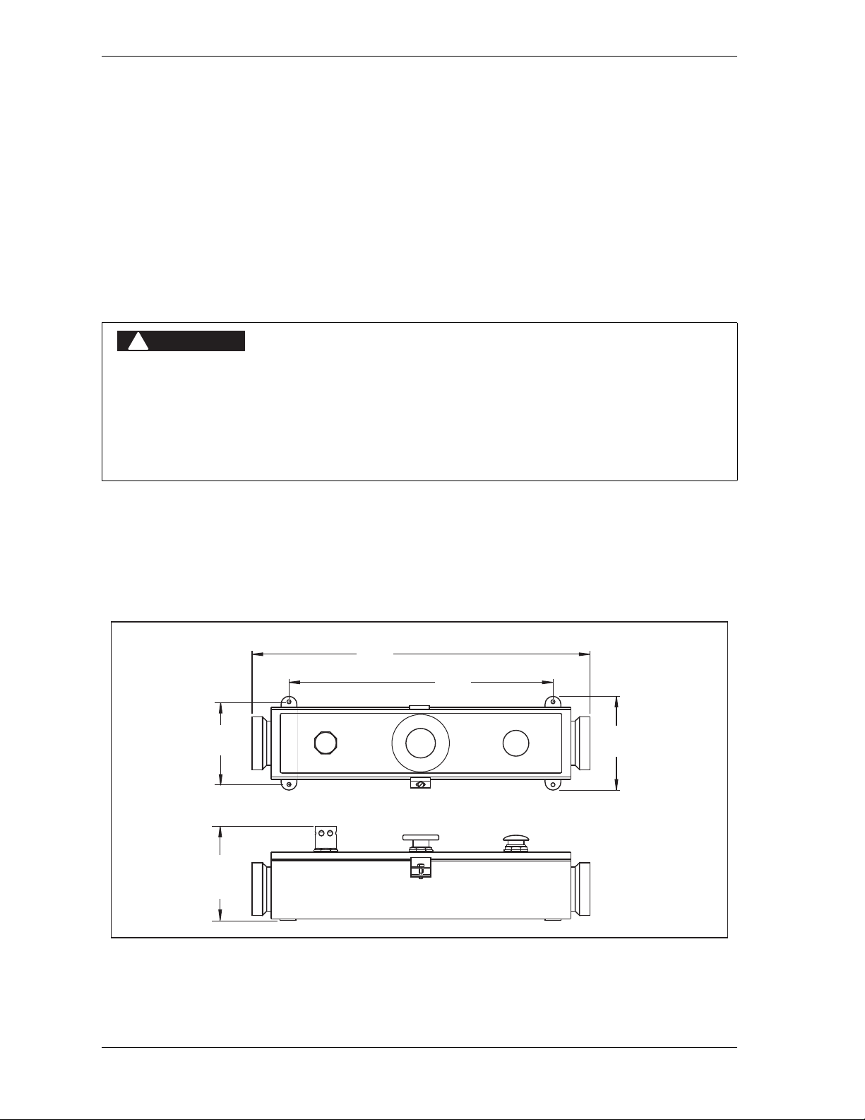
1128500 WPC 2000 User Manual
DANGER
!
Dimensions:
inches
(mm)
PRIOR
ACT
INTRISS
W
TOP
STOP
5.8
(148)
REF
4.69
(119.1)
16.75
(425.5)
R
U
N
/
I
N
C
H
R
U
N
/
I
N
C
H
5.50
(139.7)
21.25
(539.8)
E
M
E
R
G
E
N
C
Y
S
T
O
P
3. Run the Operator Station cable in the sealtight.
4. Plug the connector end of the cable into the Operator Station.
5. At the other end of the cable, connect the wires to the Main Processor board connector
terminals, as shown in Table 2-17, page 2-62 and Figure 1 at the end of the manual.
6. Mount the Operator Station in a permanent location after performing the applicable
verification and checkout tests and calculating the correct safety distance. Refer to
Figure 2-8 and Figure 2-9 (previous page) for mounting dimensions.
Wiring an Unwired Operator Station
OPERATOR STATION MAY NOT MEET SAFETY REQUIREMENTS
• Ensure that th e Operator Station is wired correctly.
• Run all necessary tests to verify that each Operator Station is wired correctly and provides
proper anti-tie-down and anti-repeat protection. Test procedures are provided at the end of this
chapter and at the end of Chapter 3.
Failure to comply with these instructions will result in death or serious injury.
To wire the unwired Wintriss Operator Station, follow the wiring diagram in Figure 7 at the
end of this manual. Before using your press, be sure to check the wiring carefully, run all the
applicable verification and checkout tests, and calculate the safety distance. You can then
mount the Operator Station in a permanent location, referring to Figure 2-10 for mounting
dimensions.
Figure 2-10. Unwired Operator Station: Mounting Dimensions
2-16 Installation
Page 44

WPC 2000 User Manual 1128500
DANGER
!
DANGER
!
NOTICE
Wiring a User-built Operator Station
NON-WINTRISS OPERATOR STATION MAY NOT MEET SAFETY REQUIREMENTS
• Ensure that th e Operator Station is wired correctly.
• Ensure that on any non-Wintriss Operator Station the Run buttons are placed so that two hands
are required to push them at the same time and that buttons cannot be pushed simultaneously
with one hand or with one hand and one elbow.
• Ensure that on any non-Wintriss Operator Station the Run buttons comply with the requirements
specified in Table B-2, page B-2.
• Ensure that on any non-Wintriss Operator Station the Run buttons have ring guards or other
means in place to prevent unintentional operation.
• Run all necessary tests to verify that each Operator Station is wired correctly and provides
proper anti-tie-down and anti-repeat protection. Test procedures are provided at the end of this
chapter and at the end of Chapter 3.
Failure to comply with these instructions will result in death or serious injury.
If you build your own Operator Station, refer to Appendix B for applicable safety
requirements. To wire your user-built Operator Station, refer to Figure 7 at the end of the
manual. Before using your press, be sure to check the wiring carefully and run all the
applicable verification and checkout tests. After calculating the correct safety distance, you
can mount the user-built Operator Station in a permanent location.
Installing Multiple Operator Stations
HAZARDS EXPOSED BY NON-WORKING OPERATOR STATION
• Safeguard the point of operation exposed by the non-working Operator Station when using
multiple Operator Stations. The exposed area near a disabled Operator Station must be
properly guarded.
• Ensure that guarding is properly installed to prevent access to the machine over, under or
around any guarding device.
Failure to comply with these instructions will result in death or serious injury.
Use light curtains in addition to multiple Operator Stations for best personnel safeguarding.
You can wire up to two Operator Stations to the WPC 2000 (see Figure 4 at the back of the
manual for dual Op. Station wiring). Make sure that switch 6 on S102 on the WPC 2000 Main
Processor board is set to OFF if you connect dual Operator Stations (see page 3-33).
If you wish to install more than two Operator Stations, contact Wintriss Tech. Support. Do
not order standard Wintriss “Multiple Operator Stations” when installing more than two Op.
Stations. All Operator Stations in a multi-Op.-Station configuration except the Op. Station
Installation 2-17
Page 45

1128500 WPC 2000 User Manual
DANGER
!
DANGER
!
NOTICE
connected to the “A” inputs must contain a Two-hand Control module. When you install
more than two Operator Stations, set switch 6 on S102 to ON.
When wiring dual operator stations, make sure to label each Operator Station correctly.
Install the label “A” prominently on the Operator Station wired into inputs for Operator
Station “A” or “1.” Install the label “B” prominently on the Operator Station wired into inputs
for Operator Station “B” or “2.” Test each Operator Station individually. Confirm that
selector switch position “A” controls Operator Station “A” and selector switch position “B”
controls Operator Station “B.” Also test switch position “Both” to confirm that it controls
both Operator Station “A” and Operator Station “B.”
Installin g a Lig ht Curtain
PREVENT OPERATOR FROM STANDING BETWEEN LIGHT CURTAIN AND HAZARDOUS AREA
Ensure that the operator cannot position himself between the light curtain and the hazardous area.
Use another pair of light curtains or a mechanical barrier at knee to waist height to prevent the
operator or a passerby from being “trapped” between the light curtain and the hazard.
Failure to comply with these instructions will result in death or serious injury.
INCORRECT LIGHT CURTAIN INSTALLATION
• Mount the light curtains at the correct safety distance as instructed in Calculating the Safety
Distance, page 3-19. The light curtain will only provide full protection for operators when
mounted at the correct safety distance .
• Install and wire your light curtains correctly, following the instructions in your Shadow manual
and referring to Figures 3, 10, 11, 15, 16, 18, and 19 at the end of this manual.
Failure to comply with these instructions will result in death or serious injury.
The light curtain is normally mounted in front of the die space and must be located at least the
safety distance from the pinch point. This location ensures that the light curtain can send a
Stop command to the press in time for the press to stop before anyone can reach the pinch
point. Any opening or access to the die space that is not guarded by the light curtain must be
guarded by mechanical barriers.
To determine the Stopping Time of the press, refer to page 3-14. To calculate the correct
safety distance, see page 3-19.
You cannot permanently mount the light curtain until the WPC 2000 is working properly and you
have measured the Stopping Time, set the brake monitor, and calculated the correct safety
distance. However, you will be able to wire the light curtain.
2-18 Installation
Page 46

WPC 2000 User Manual 1128500
WARNING
!
WPC 2000 provides wiring connections for up to two pairs of light curtains (see Table 2-17,
page 2-62). If you wire two sets of light curtains, you must enable them on S101 option
switch 6 (see Table 3-9, page 3-29).
Installing Shadow Light Curtains
Wiring connections for Shadow light curtains are provided in the following wiring diagrams
at the back of the manual:
• Shadow V–Figure 3
• Shadow VI–Figure 10
• Shadow VI Integrated–Figure 11
• Shadow VII–Figures 15 and 16
• Shadow 8–Figures 18 and 19
For Shadow I or Shadow II wiring, contact Wintriss Tech. Support. For complete Shadow
light curtain mounting instructions, see your Shadow user manual.
Setting Jumpers for Shadow VII and Shadow 8 Light Curtains
When you install Shadow VII or Shadow 8 light curtains on your press, you must set jumpers
JP121-JP124 on the WPC 2000 Main Processor board (see Figure 2-12, page 2-23 or
Figure 2-13, page 2-24) to the positions shown in Table 2-1. Wiring diagrams are provided in
figures 15 (Shadow VII control box), 16 (Shadow VII DIN controller), 18 (Shadow 8 optional
control), and 19 (Shadow 8 wired directly to WPC 2000) at the back of the manual.
Table 2-1. Shadow VII and Shadow 8 Light Curtain Jumper Settings
Jumper on Main
Processor Board Settings
Light Curtain #1
Light Curtain #2
JP123 PNP
JP124 INT
JP121 PNP
JP122 INT
Installing Non-Shadow Light Curtains
It is your responsibility to ensure that your light curtains are control reliable and intended for use on
a mechanical power press as a primary point-of-operation guard. The manufacturer of your light
curtain should be able to provide the necessary information.
Failure to comply with these instructions could result in death or serious injury.
Installation 2-19
Page 47

1128500 WPC 2000 User Manual
DANGER
!
CAUTION
If you plan to interface a light curtain system other than Shadow with your WPC 2000, please
call Wintriss Tech. Support for instructions. Be ready to provide the following information:
• Light curtain manufacturer
• Light curtain model number
• WPC model (i.e., WPC 2000)
• WPC 2000 firmware version number (located on A or B microprocessor chip label)
• Wiring diagram from the light curtain manufacturer’s manual
If your WPC 2000 does not have the firmware that allows Foot or One-Hand control and/or
muting of a light curtain on the upstroke, you can connect the light curtain’s dry contact
outputs directly in series with WPC 2000’s E-stop string.
Installing the Resolver
RESOLVER OUT OF SYNCH WITH CRANKSHAFT
Retain the sprockets on the crankshaft and resolver shaft mechanically so they cannot shift or
move out of radial alignment. Be sure that the key on the resolver shaft retains the resolver
sprocket. Use a pin or other method to fix the position of the sprocket on the crankshaft.
Failure to comply with these instructions will result in death or serious injury.
Because the resolver must provide WPC 2000 with the exact position of the crankshaft at
every degree of the stroke (see Resolver, page 1-1), the device must be driven smoothly at a
1:1 ratio with the crankshaft of the press. Design a method of driving the resolver directly
from the crankshaft, using a chain or timing belt (not a V belt) and sprockets. Use either an
idler sprocket or a spring-loaded resolver base to compensate for slack or stretch.
DAMAGE TO RESOLVER
Be sure that the sprocket or gear driving the resolver chain or timing belt is mounted so it is
centered on the crankshaft. If the gear or sprocket is mounted off-center, the resulting loads on
the resolver shaft may cause the unit to fail.
Failure to comply with these instructions could result in property damage.
The drive method you choose must also allow for adjustment of the resolver to its zero
position at top dead center. All sprockets must be keyed or pinned. The resolver shaft has a
standard key. Wintriss Controls Group stocks a spring-loaded base with a hole pattern to
match the resolver.
When designing the drive for the resolver, observe the following precautions:
• Do not use a chain more than three feet in length
• Do not use gears, right-angle joints, or shafts with universal joints, which will develop
either too much backlash or too much play
2-20 Installation
Page 48
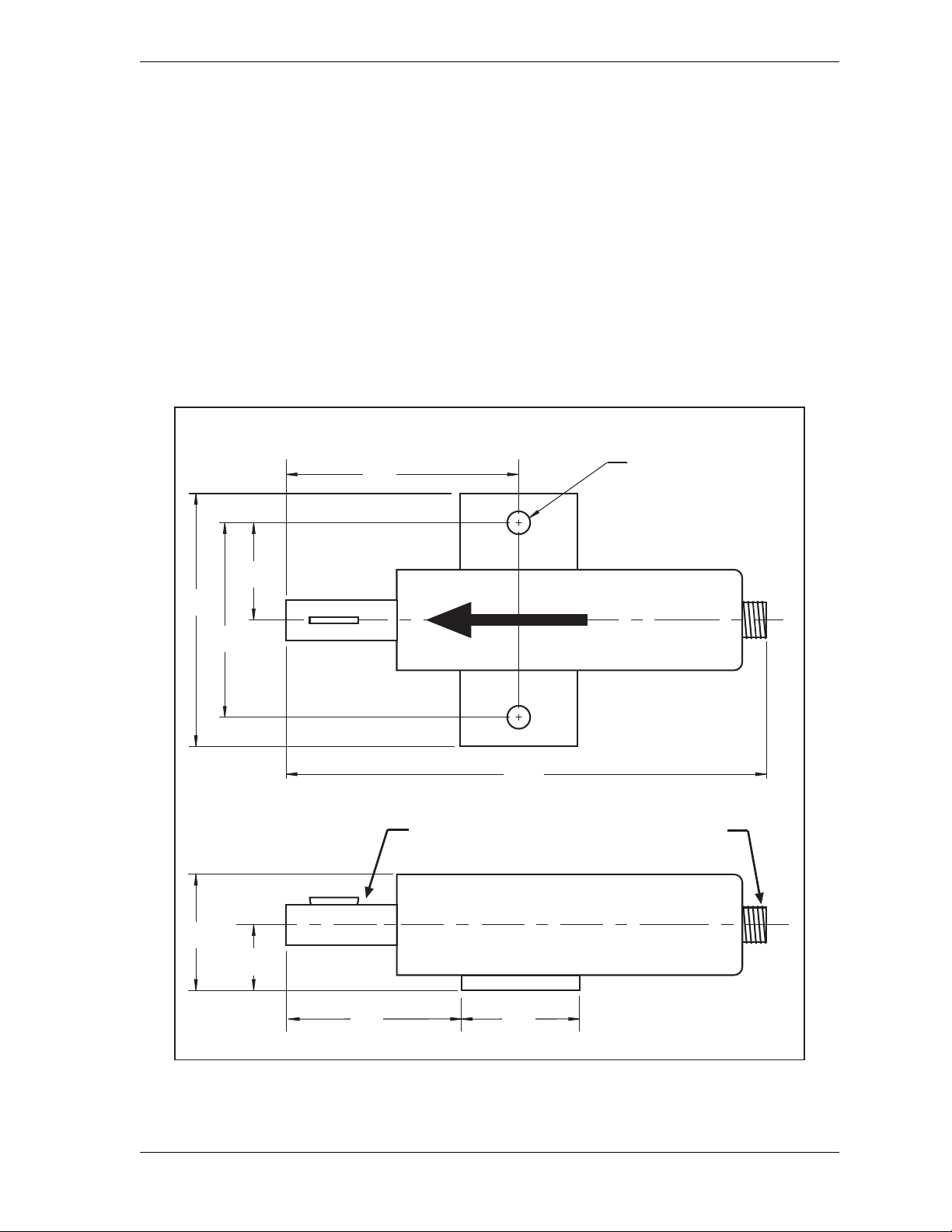
WPC 2000 User Manual 1128500
2.75
(69.9)
1.06
(26.9)
1.75
(44.5)
2.00
(50.8)
3/4 dia. shaft (19.05)
standard key
Electrical connector
for cable
3.62
(91.9)
0.34 (8.6) dia holes
2 places
9.16
(232.7)
RESOLVER IS AT ZERO WHEN
KEYWAY IS ALIGNED WITH ARROW
3.00
(76.2)
3.75
(95.3)
1.50
(38.1)
Resolver shown in
zero-degrees position,
with key perpendicular
to base
Dimensions: inches
(mm)
• Do not try to couple the resolver directly to the crankshaft. Such a placement requires
extreme precision. If the resolver is only slightly off-center , its bearing will be subjected to
side loads well in excess of its rated capacity and will ultimately fail.
• Do not use flexible couplings, which can be inaccurate, or V belts, which can also be
inaccurate and will slip
• Do not use a flexible shaft like a speedometer cable. The resolver will lag the crankshaft
because of the twisting of the shaft on start-up. When the crankshaft stops, the resolver will
turn past the true stopping point and snap backward.
Mounting the Resolver
To mount the resolver, perform the following steps:
Figure 2-11. Resolver: Mounting Dimensions
Installation 2-21
Page 49

1128500 WPC 2000 User Manual
NOTICE
NOTICE
NOTICE
It does not matter which direction the resolver turns when the press runs. You adjust for the
direction of rotation when you wire the unit (see Wiring the Resolver, next section).
1. Mount the resolver by bolting it to the press or other platform at the desired location.
2. Make sure the press is at TDC.
3. Rotate the resolver shaft so that the keyway is aligned with the arrow on the housing (see
Figure 2-11).
4. Keeping the keyway aligned with the arrow, attach the chain or drive mechanism.
Wiring the Resolver
To wire the resolver, perform the following steps:
1. If the resolver cable is not already connected to the resolver, locate the cable, plug the
molded connector into the resolver (it only goes one way), and twist the locknut so the
connection is tight.
2. Run the resolver cable through conduit from the resolver to one of the knockouts in the
bottom of the WPC 2000 enclosure.
You can run the resolver and overrun limit switch cables through the same conduit (see
Figure 2-1, page 2-4 for an example). If you do so, make sure not to cut the cable and
wires until both the resolver and the overrun limit switch are installed.
3. Find the resolver terminal block, TB 106, on the WPC 2000 Main Processor board (see
Figure 2-12, page 2-23 or Figure 2-13, page 2-24), and remove the L-shaped connector.
4. Viewing the resolver from the shaft end, determine whether the shaft will turn clockwise
or counterclockwise when the press runs.
5. Measure and cut the resolver wires so they reach TB 106, then wire them to the L-shaped
connector, referring to T able 2-21, page 2-63, and Figure 2 at the end of the manual. Make
sure you connect the black and yellow wires correctly, based on the direction in which
your resolver will rotate–clockwise or counterclockwise. Refer to Connecting Wires to
Terminal Block Connectors, page 2-5 if you need help wiring the TB 106 connector.
CONNECTOR WIRING
Before wiring, place the connector over its base the way it will plug in (it can plug in only
one way) and double-check pin assignments to make sure you wire correctly.
6. Double-check connections when you are finished wiring.
7. Plug the L-shaped connector firmly into its base. It can plug in only one way.
2-22 Installation
Page 50
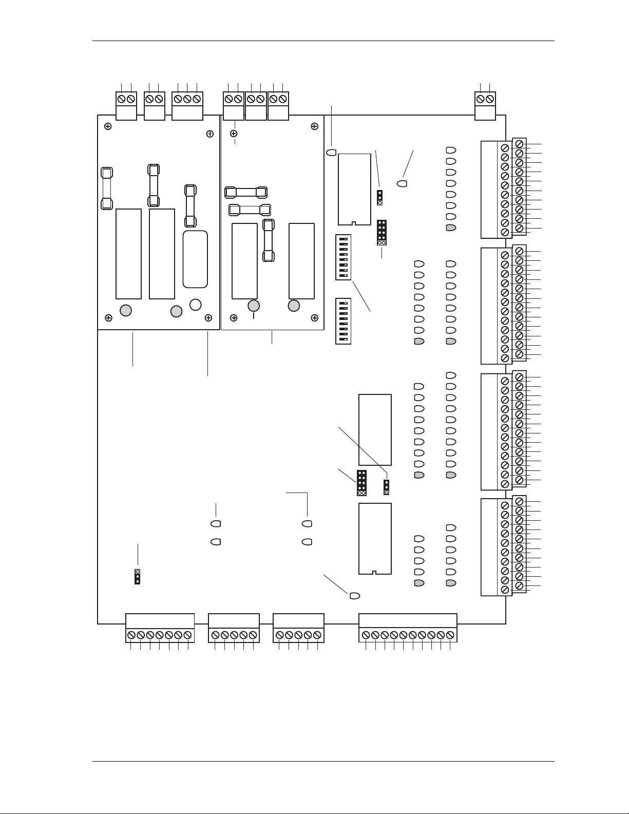
WPC 2000 User Manual 1128500
TB 106
Resolver
TB 108
Display cable
TB 109
Cam outputs
TB 107
Serial port
TB 303
DS 302
DS 301
DS 303
TB 302 TB 301
TB 403
TB 402 TB 401
TB 105
Power
F 303
F 302
DSV/Lockout relay board
Aux. E-stop relay board
(Optional)
DS 401
DS 402
TB101
TB104
TB103
LEDs
LEDs
Hi/Lo speed
jumper
JP126
(underneath
DSV/Lockout
relay board)
Light
curtain A
output type
jumper
JP123
Hi/Lo speed
jumper
JP125
Transmit
DS1381
Receive
DS1371
Transmit
DS1421
Receive
DS1431
Serial
port LEDs
Display
cable LEDs
Light curtain B
test mode
jumper
JP122
+ 24V I/O
LED
DS150
+5V A processor
LED
DS149
Light curtain B
output type
jumper
JP121
Light curtain A
test mode
jumper
JP124
+5V B processor
LED
DS151
Option
switches
S101
Option
switches
S102
Green
OrangeGreen
Green
Green Orange
TB102
Green Orange
LO
HI
INT
EXT
PNP
NPN
RAM
chip
U102
A
pro-
cessor
chip
U111
ON
87654321
ON
87654321
B
pro-
cessor
chip
U134
INT
EXT
PNP
NPN
LED #
1
45
2
3
4
5
6
7
8
9
10
46
47
48
49
50
51
52
53
54
11
12
13
14
15
16
17
18
19
20
21
22
23
24
25
26
27
28
29
30
31
32
33
34
35
36
37
38
39
40
41
42
43
44
55
56
57
58
59
60
61
62
63
64
65
66
68
69
70
71
72
73
74
75
76
77
78
67
79
80
81
82
83
84
85
86
87
88
8990919293949596979899100101102103
105104 107106 109108 110 112111 114113 115 117116 119118 120 122121 124123 125 127126 129128 130
DSV ADSV B
1
6
5
4
3
2
1
8
7
6
5
4
3
2
9
10
1
8
7
6
5
4
3
2
1
8
7
6
5
4
3
2
Group 4Group 3
Group 1 Group 2
Group 5 Group 6
Group 7
Installation 2-23
Figure 2-12. WPC 2000 Main Processor Board (Right or Center Configuration):
Location of Important Component s
Page 51
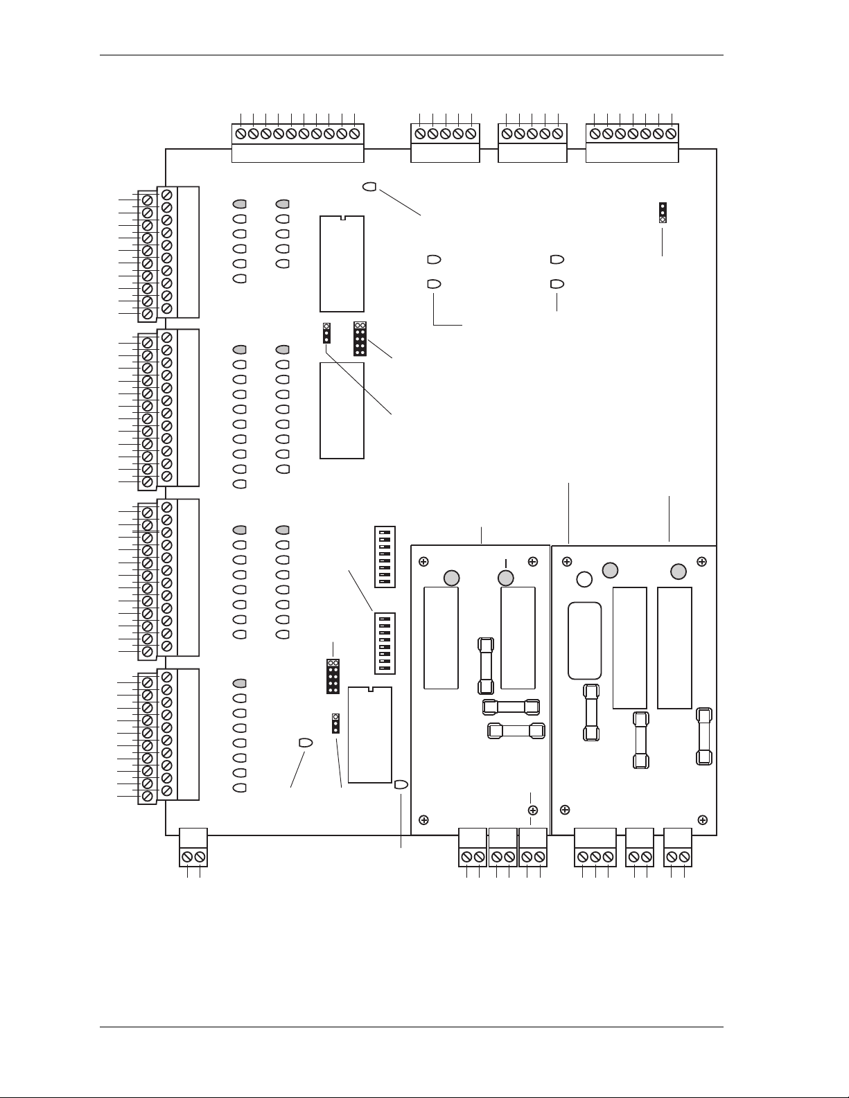
1128500 WPC 2000 User Manual
TB 106
Resolver
TB 108
Display cable
TB 109
Cam outputs
TB 107
Serial port
TB 303
DS 302
DS 301
DS 303
TB 302TB 301
TB 403
TB 402TB 401
TB 105
Power
F 303
F 302
DSV/Lockout relay board
Aux. E-stop relay board
(Optional)
DS 401
DS 402
TB101
TB104
TB103
LEDs
LEDs
Hi/Lo speed
jumper
JP126
(underneath
DSV/Lockout
relay board)
Light
curtain A
output type
jumper
JP123
Hi/Lo speed
jumper
JP125
Transmit
DS1381
Receive
DS1371
Transmit
DS1421
Receive
DS1431
Serial
port LEDs
Display
cable LEDs
Light curtain B
test mode
jumper
JP122
+ 24V I/O
LED
DS150
+5V A processor
LED
DS149
Light curtain B
output type
jumper
JP121
Light curtain A
test mode
jumper
JP124
+5V B processor
LED
DS151
Option
switches
S101
Option
switches
S102
Green
Orange Green
Green
GreenOrange
TB102
GreenOrange
LO
HI
INT
EXT
PNP
NPN
RAM
chip
U102
A
pro-
cessor
chip
U111
ON
87654321
ON
87654321
B
pro-
cessor
chip
U134
INT
EXT
PNP
NPN
LED #
1
45
2
3
4
5
6
7
8
9
10
46
47
48
49
50
51
52
53
54
11
12
13
14
15
16
17
18
19
20
21
22
23
24
25
26
27
28
29
30
31
32
33
34
35
36
37
38
39
40
41
42
43
44
55
56
57
58
59
60
61
62
63
64
65
66
68
69
70
71
72
73
74
75
76
77
78
67
79
80
81
82
83
84
85
86
87
88
89 90 91 92 93 94 95 96 97 98 99 100101 102 103
105104107106109 108110112 111114 11311511 711 611 911 8120122121124123125127126129128130
DSV A DSV B
1
6
5
4
3
2
1
8
7
6
5
4
3
2
9
10
1
8
7
6
5
4
3
2
1
8
7
6
5
4
3
2
Group 4 Group 3
Group 1Group 2
Group 5Group 6
Group 7
2-24 Installation
Figure 2-13. WPC 2000 Main Processor Board (Left Configuration):
Location of Important Component s
Page 52

WPC 2000 User Manual 1128500
DANGER
!
Checking the Resolver’s Direction of Rotation
To determine whether you have wired the resolver so that it rotates in the correct direction, do
the following:
1. Run the press in Inch mode, and observe whether the crankshaft angle shown in the digital
LED display increases or decreases.
• If the angle increases (i.e., moves from 0° to 1°, 2°, 3°, etc.), the resolver wiring is
correct. Go to the next section.
• If the angle decreases (moves from 0° to 359°, 358°, 357° etc.), the yellow and black
resolver wires are reversed. Go to step 2.
2. Rewire the yellow and black resolver wires correctly, referring to Table 2-21, page 2-63
and Figure 2 at the end of the manual.
3. Inch the press again, and observe the movement of the crankshaft angle in the LED
display. The angle should now increase.
4. If the direction of rotation is still incorrect, contact Wintriss Tech Support.
Replacing the Resolver
If you need to replace your resolver, do the following:
1. Perform the Mounting the Resolver and Wiring the Resolver procedures, above.
2. Rezero the resolver, following the instructions in Re-zeroing the Resolver, page 3-4.
Installing the Overrun Limit Switch
MOUNT OVERRUN LIMIT SWITCH SO IT PROVIDES CORRECT TIMING
• Install the overrun limit sensor magnet on a component, such as the crankshaft, that moves
independent of the resolver and whose motion is not affected by the condition of the resolver or
the resolver’s drive mechanism. Safe operation of the press depends on the overrun limit
sensor working correctly when the resolver or its drive mechanism fails.
• Install the overrun limit sensor magnet in the correct angular location according to the
instructions starting on page 3-6.
Failure to comply with these instructions will result in death or serious injury.
The overrun limit sensor, also called the “overrun sensor,” enables WPC 2000 to monitor
operation of the resolver and to stop the press whenever the resolver fails to work properly, as
can happen when the resolver drive chain breaks or slips or when the resolver is broken. The
overrun sensor provides a signal to WPC 2000 at the same resolver angle on every stroke.
Whenever this angle changes, WPC 2000 detects that the resolver is no longer rotating at a 1:1
ratio with the crankshaft and sends an Emergency-stop command to the press, simultaneously
displaying an error code.
Installation 2-25
Page 53
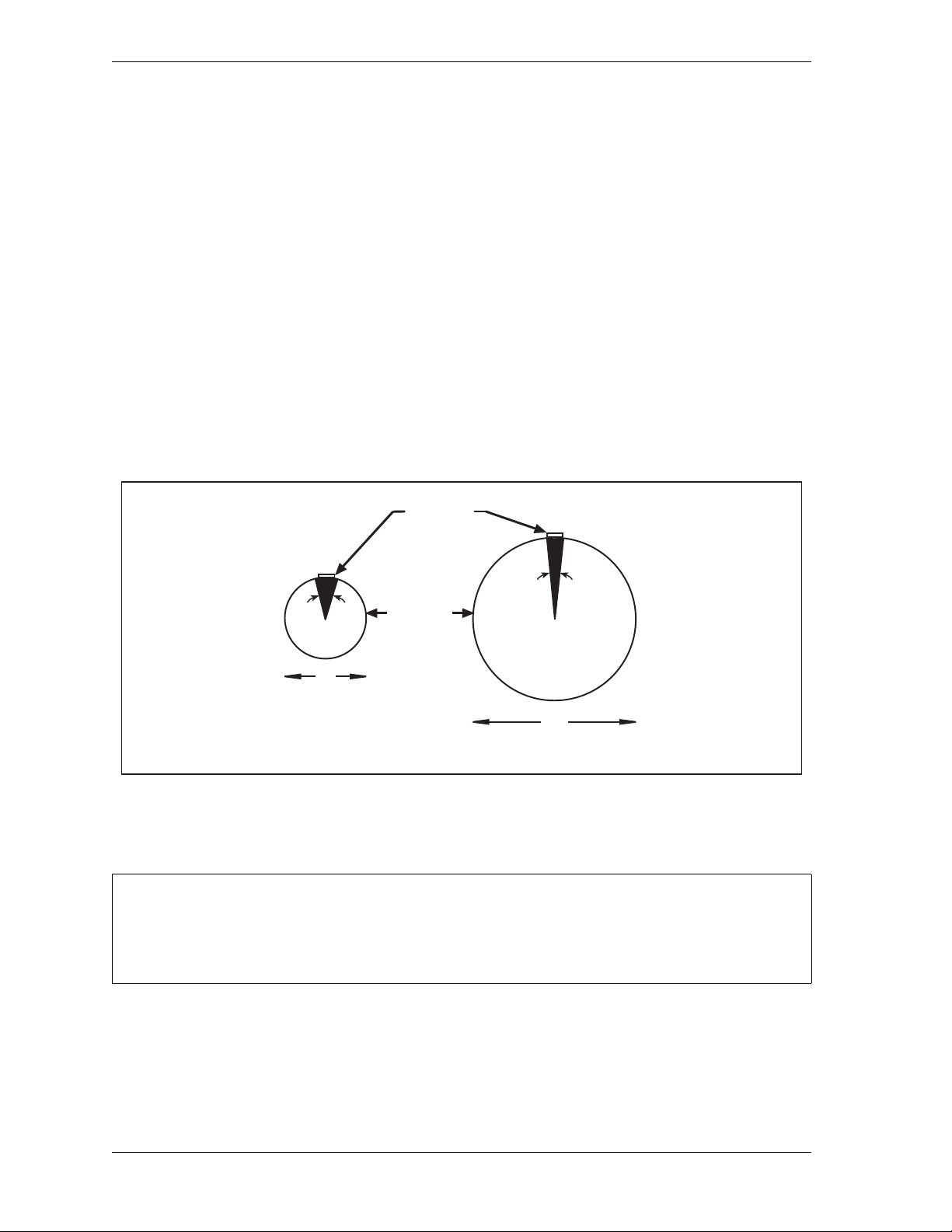
1128500 WPC 2000 User Manual
10
Actuating
Magnet
5 (127 mm) diameter
23 of dwell
o
10 (254 mm) diameter
11 of dwell
o
Crankshaft
5
23
o
11
o
Optimum dwell: 15 to 25
oo
NOTICE
Planning Your Overrun Sensor Installation
The overrun sensor consists of a magnetic switch and a magnet. Select a mounting location
for both components that ensures that the magnet moves past the switch once on every stroke
and within 1/8 in. to 3/16 in. (3 mm to 5 mm) of the switch, close enough for the switch to
sense the magnet’s presence. The magnet is mounted to the crankshaft or another component
that rotates identically on every stroke. The switch is hard-mounted to the press or other
surface and remains stationary.
There must be no connection between the overrun limit sensor and the resolver to ensure that
the overrun sensor continues to operate if the resolver or its drive mechanism fails.
To obtain an adequate overrun signal at high speeds, the magnet should be mounted so that it
can be sensed by the switch for 15° to 25° of the stroke. The interval during which the magnet
is sensed, called the “dwell,” decreases as the diameter of the rotating shaft increases (see
Figure 2-14). Select a shaft whose diameter will allow the sensor to detect the ma gnet fo r the
required dwell.
Figure 2-14. Overrun Sensor Magnet Placement: Dwell as a Function of Shaft Diameter
Mounting the Overrun Sensor Switch
INSTALL MAGNET AFTER MOUNTING SWITCH
Install the overrun magnetic switch as instructed in this section. Refer to page 3-6 for instructions
on installing the overrun magnet.
The overrun sensor magnetic switch comes already installed in a bracket. Mount the bracket
and switch at a location past which the magnet will pass on every stroke and within 1/8 in. to
3/16 in. (3 mm to 5 mm) of the magnet, referring to Figure 2-15, page 2-27.
2-26 Installation
Page 54
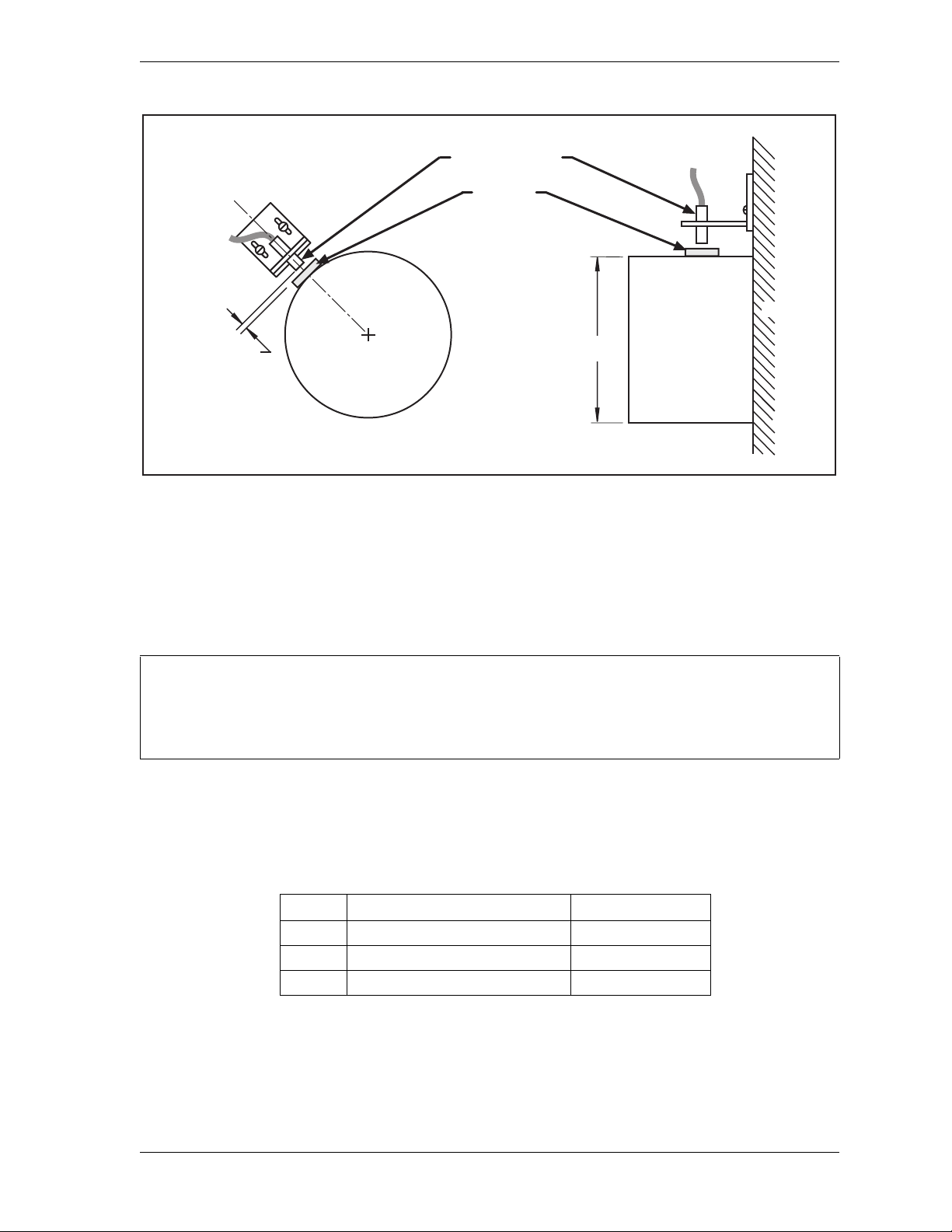
WPC 2000 User Manual 1128500
Crankshaft
Gap between
magnet and
magnetic switch
1/8 to 3/16
Crankshaft
Press
Magnetic switch
Magnet
Mount temporarily
with tape.
Hard mount later.
Diameter
4-6
NOTICE
Figure 2-15. Overrun Sensor Magnetic Switch: Installation Example
Place the magnet temporarily on the crankshaft or other mounting surface while you set the
gap between the switch face and the magnet. After tightening down the bracket’s mounting
screws, remove the magnet and put it in a safe place until you mount it permanently.
Wiring the Overrun Sensor Switch
You can run both the resolver wires and the overrun limit sensor cable through the same conduit.
If you do so, wait to cut the cable and wires until both the resolver and the overrun limit sensor are
installed.
Run the cable for the magnetic switch through conduit to the WPC 2000. Connect the wires to
terminal blocks on the WPC 2000 Main Processor board, as shown in Table 2-2 and Figure 2
at the end of the manual.
Table 2-2. Overrun Sensor Switch Wiring Connections
Pin # Signal Wire Color
23 +24 Vdc Red
24 Overrun input to WPC 2000 White
25 Ground Black
Installation 2-27
Page 55

1128500 WPC 2000 User Manual
DANGER
!
DANGER
!
DANGER
!
DANGER
!
Wiring WPC 2000 User Inputs
USER INPUTS 1 THROUGH 7 NOT SUITABLE FOR SAFETY USE
DO NOT use inputs 1 through 7 as part of any personnel-protection system. These inputs are not
control reliable.
Failure to comply with these instructions will result in death or serious injury.
USER INPUTS ADD DELAY TO STOPPING TIME
DO NOT connect light curtains or other presence-sensing devices to any user inputs. The crosschecked input pairs (8/9 and 10/11), though control reliable, are suitable only for applications such
as connecting to safety switches used with interlocking barrier guards.
Failure to comply with these instructions will result in death or serious injury.
MAKE SURE TO WIRE CROSS-CHECKED INPUT PAIR CORRECTLY
Input pairs 8/9 and 10/11 are control reliable only if wired correctly in a pair according to the
instructions in this section.
Failure to comply with these instructions will result in death or serious injury.
CHECK PRESS TO MAKE SURE IT STOPS WHEN USER INPUT ACTUATES
• WPC 2000 comes from the factory with the inputs bypassed by jumpers. Make sure to remove
the appropriate jumper from the Main Processor board connector when you wire a user input.
Otherwise, WPC 2000 will not receive the signal from the input. Leave all unused inputs
jumpered/bypassed.
• Perform checkout procedures to ensure that the user inputs are wired correctly and that WPC
2000 responds correctly when the user input faults (see page 3-58).
Failure to comply with these instructions will result in death or serious injury.
WPC 2000 user inputs allow you to connect signals from other equipment in order to monitor
auxiliary press functions such as lubrication systems. WPC 2000 provides connections for
two pairs of control-reliable, cross-checked inputs and seven independent inputs that are not
control reliable.
When one of these inputs issues a Stop command by opening a normally closed (N/C) relay, a
fault code for the input(s) appears on the LED display. User inputs 1, 2 and 4 and crosschecked input pair 8/9 issue an Emergency-stop command. User inputs 3, 5, and 6 generate a
Top-stop command. User input 7 and cross-checked input pair 10/11 generate an Emergency
Stop, simultaneously opening the Lockout relay and displaying the “Loc” message on the
digital LED readout. The stop type, fault code, and wiring connections for each input are
shown in Table 2-3, page 2-29.
2-28 Installation
Page 56

WPC 2000 User Manual 1128500
NOTICE
Table 2-3. WPC 2000 User Inputs: Stop Types, Fault Codes, and Wiring Connecti ons
Jumper
User Input
(Interlock) Stop Type
User 1 ESTOP 21 +24 Vdc 51
User 2 ESTOP 82 +24 Vdc 52
User 3 TOP STOP 71 +24 Vdc 53
User 4 ESTOP 83 Ground 54
User 5 TOP STOP 72 Ground 55
User 6 TOP STOP 84 Ground 56
User 7 ESTOP/
LOCKOUT
User 8 paired
with 9
User 9 paired
with 8
User 10 paired
with 11
User 11 paired
with 10
ESTOP
ESTOP/
LOCKOUT
Pin
73 Ground 57
85 Ground
74 Ground
86 Ground
18 Ground
#
Connection
(Bypass)
Fault
Code
58, 17
50, 18
Name of Auxiliary
Equipment
The cross-checked input pairs generate a fault either when one or both inputs in the pair are
open or when the inputs “disagree” (i.e., one input is open, the other closed) for longer than
100 mS. Cross-checked input pair 10/11 can be used to detect critical safety problems such as
the removal of die receptacle blocks.
Since faults for input 7 and cross-checked input pair 10/11 open the Lockout relay, you can
wire this relay to your motor starter so that ungrounding of input 7 or of either input in the
input pair will shut off the motor.
To clear the “Loc” message on the LED display, turn the Stroke Select switch to OFF and then
back to INCH (see Wiring the Lockout Relay, next section, and Lockout Message, page 5-3).
ALL SIGNAL GROUNDS MUST BE CONNECTED THROUGH THE MAIN PROCESSOR BO ARD
Connect all signal grounds through pins on the WPC 2000 Main Processor board.
To wire the user inputs, run conductors from the appropriate terminal number on the Main
Processor board to your equipment and then back to either +24 Vdc or ground, as shown in
Table 2-3 and Figure 2 at the end of the manual. (There are several available “Ground” and
“+24 Vdc” terminals on the Main Processor board from which to choose.) After you have
wired the inputs you will use, be sure to bypass all the unused inputs by connecting them to
+24 Vdc or Ground.
Installation 2-29
Page 57

1128500 WPC 2000 User Manual
NOTICE
DANGER
!
If you do not bypass the unused inputs, WPC 2000 will not work properly.
You can add up to 20 more non-control-reliable user inputs and up to 4 more control-reliable,
cross-checked user inputs to your WPC 2000 by purchasing the Option 1 “daughter” board,
which you install on the WPC 2000 Main Processor board. If you are interested in this
product, contact your local Wintriss representative or call Wintriss Tech. Support. To install,
wire, and troubleshoot the Option 1 board, refer to Appendix C.
Wiring the Lockout Relay
The Lockout relay, which is designed to be wired to critical press functions such as the motor
starter, provides an added safety feature to WPC 2000. Whenever a serious error condition
occurs, the “Loc” message will appear in the digital LED display. To clear the “Loc”
message, turn the Stroke Select switch to OFF, then back to INCH or one of the other
operating modes.
Wire the function you want to be controlled by the Lockout relay to TB 301 on the DSV/
Lockout relay board, which is located in the upper left corner (see Figure 2-12, page 2-23) or
lower right corner (see Figure 2-13, page 2-24) of the WPC 2000 Main Processor board.
Wiring connections are shown in Table 2-4 and in Figures 13 (Herion DSV), 14 (Ross Serpar
DSV), and 17 (Ross DM2 DSV) at the end of the manual.
Table 2-4. Lockout Relay Wiring Connections (DSV/Lockout Relay Board)
TB301
Pin # Signal
97 Lockout relay input
98 Lockout relay output
99 Lockout relay output
Wiring Auxiliary Outputs
NON-SAFETY OUTPUT USED FOR SAFETY FUNCTIONS
Use Auxiliary outputs 1, 2, and 3 for non-safety functions only , such as convenience in automation.
They cannot protect personnel from a moving hazard.
Failure to comply with these instructions will result in death or serious injury.
WPC 2000 provides three optional Auxiliary outputs that you can use to automate equipment
connected to your clutch/brake control. A summary of wiring connections and change
conditions for these three outputs is provided in Table 2-5, page 2-31. Details about each
output are given following the table. Additional wiring details are provided in Table 2-17,
page 2-62 and in Figure 2 at the back of the manual.
2-30 Installation
Page 58

WPC 2000 User Manual 1128500
Table 2-5. Auxiliary Output Wiring Connecti ons and Ch ange Con ditions
Pin #
(WPC 2000
Output
Aux. 1 28 On (N/C) Off (or Open) • WPC 2000 fault
Aux. 2 36 Off (N/O) On (or Closed) • WPC 2000 fault
Aux. 3 29 Off (N/O) On (or Closed) • DSV energized
Cntrl Bd.)
Normal
State
Change
State Change Conditions
• E-stop string open
• Light curtain interruption
• Interrupted Stroke (controlled by
option switch 8–see Table 2-6)
• Interrupted stroke
• Key switch in Inch and DSV energized
Auxiliary Output 1
Auxiliary 1 is normally closed (N/C), or On. The output opens, or turns Off, when a fault
condition occurs, an E-stop string opens, or a light curtain is interrupted while the press is
running. The output can also be programmed to turn Off during an Interrupted Stroke (see
page 4-3 for an explanation of Interrupted Stroke).
Aux. Output 1 response to an Interrupted Stroke is controlled by option switch 8 on the WPC
2000 Main Processor board. Switch settings are shown in Table 2-6.
Table 2-6. Option Switch 8 Settings for Auxiliary Output 1 State Change
Option Switch 8 Auxiliary Output 1 State Change during Interrupted Stroke
OFF Output turns OFF when an Interrupted Stroke occurs
ON Output remains ON during an Interrupted Stroke unless the Interrupted Stroke
is preceded by a WPC 2000 fault or an Emergency Stop, in which case the
output turns OFF
When switch 8 is set to OFF, Auxiliary Output 1 opens, or turns Off, at the occurrence of an
Interrupted Stroke. When switch 8 is set to ON, the output turns Off during an Interrupted
Stroke only when there is also a fault or Emergency-stop condition; otherwise, the output
remains On during an Interrupted Stroke. See Auxiliary Output 1 Response to Interrupted
Stroke, page 3-31 for additional details.
The switch 8 ON setting allows the press to be “inched” during an Interrupted Stroke, when
the WPC 2000 is in Two-hand Maintained Single-stroke mode. Normally, in Two-hand
Maintained Single-stroke, the operator must hold down the Run/Inch palm buttons until the
press reaches its Top-stop position in order to avoid another Interrupted Stroke. With switch 8
set to ON, the operator may release the Run/Inch buttons while inching the press to Top-stop
without initiating an Interrupted Stroke.
Auxiliary Output 1 can be wired to a customer-supplied control relay and used to stop
auxiliary equipment such as scrap choppers, conveyors, etc. when one of the conditions
described above causes the press to stop. When a warning beacon is connected to the control
relay, the beacon illuminates when a fault occurs and Aux. Output 1 opens.
Installation 2-31
Page 59

1128500 WPC 2000 User Manual
NOTICE
Auxiliary Output 2
Auxiliary Output 2 is normally open (N/O), or Off. The output closes to ground, or turns on,
whenever there is an interrupted stroke or fault condition or the press is placed in Inch mode.
Auxiliary Output 2 can be connected to the Setup Mode inputs of DiPro 1500 and AutoSet
1500/1504 Plus. The output is used to disable green sensors in DiPro 1500 or repeatability
setpoints in AutoSet 1500/1504 Plus whenever the press is switched to Inch mode or an
interrupted stroke or fault condition occurs. A customer-supplied output relay can be wired
into this circuit. Refer to the applicable manuals for wiring details.
Auxiliary Output 3
Auxiliary Output 3 is normally open (N/O), or Off. The output closes, or turns On, when the
DSV is energized. When Bar Control is in use (see Operating the Press in Bar Mode,
page 4-19), Aux. Output 3 remains open, or Off, when the DSV is energized.
Auxiliary Output 3 can be wired to the input check circuit of DiPro 1500 or ProCam 1500 and
is used to prevent Loss of Rotation faults on these units when Bar Control is activated.
When WPC 2000 is in Bar Control mode, the DSV is energized to enable the crankshaft to be
turned by hand. Under normal conditions, whenever the DSV is energized, Aux. Output 3
turns On, sending a low voltage (i.e., 24 Vdc) input check signal to the DiPro 1500 or ProCam
1500.
DiPro/ProCam 1500 uses the input check signal to initiate monitoring of the programmed start
time limit, the interval within which the crankshaft must begin rotating in order to avoid a
Loss of Rotation fault. In Bar Control mode, Aux. Output 3 disables the input check signal,
preventing the 1500 unit from monitoring the start time limit.
Wire Auxiliary Output 3 to the “A” connection of the input check circuit of DiPro 1500 or
ProCam 1500. Wire one of the +24 Vdc outputs on the WPC 2000 Main Processor board
(pins #37 through #42) to the “B” connection of DiPro 1500 or ProCam 1500. If your DiPro
1500 or ProCam 1500 is equipped with a voltage selector switch for the input check circuit,
set it to the 12-60 volt position. Refer to the DiPro 1500 or ProCam 1500 manual for details.
Connecting Multiple Controls to the Resolver
MAKE WPC 2000 THE “MASTER” WHEN CONNECTING MULTIPLE CONTROLS
When connecting multiple controls to the resolver, make sure that the connection between the
resolver and WPC 2000 is direct, thereby making WPC 2000 the “master” control. Wire the other
Wintriss controls in parallel to the resolver as “slaves.”
You can connect the resolver to as many as three additional Wintriss controls (e.g., WPC
2000, DiPro 1500). To do so, perform the following steps:
2-32 Installation
Page 60

WPC 2000 User Manual 1128500
1. Check the resolver connector TB106 on the WPC 2000 Main Processor board (see
Figure 2-12, page 2-23 or Figure 2-13, page 2-24) to make sure that the resolver is wired
to the WPC 2000 as instructed on page 2-22.
2. Locate the 7-conductor shielded resolver cable. Run the cable through 1/2 in. conduit
from the WPC 2000 to the other control. If there is a connector on one end of the cable,
cut it off.
3. Pull the TB106 resolver connector out of its socket.
4. Attach the wires to TB106 as shown in Table 2-21, page 2-63 and in Figure 2 at the end of
the manual. You will be wiring in parallel (#104 brown to brown, #105 orange to orange,
etc.), so that when you are finished, you should have two wires of the same color
connected to each terminal on that connector.
5. Connect the cable from TB106 to the resolver connector in the first “slave” unit.
Remember to wire in parallel.
6. Locate the master/slave jumper on the Main Processor board of the “slave” unit(s). Move
each of these jumpers to the pins designating “slave.” Refer to the applicab le user manual.
7. Repeat steps 5 and 6 to connect additional “slave” units.
Connecting Other Wintriss Products to WPC 2000
You can connect other Wintriss products to WPC 2000, such as DiPro 1500 and ProCam
1500. Before you wire, complete all WPC 2000 installation, initialization and checkout
procedures. Then run the press in all modes of operation–Inch, Single-stroke, and Continuous
(if applicable). Also make sure that the press has working Top-stop and Emergency-stop
circuits. Since WPC 2000 is connected to the press stop circuits, it is extremely important to
verify that the press operates and stops properly before connecting WPC 2000 to other units.
Do not forget to mark on your electrical prints where you wire in WPC 2000.
When the Stopping Time is critical to your operation, as it is with die protection, be sure to
wire as follows. Whenever you have Emergency-stop circuits, wire them between terminals
#67 and #68 or terminals #68 and #69 on the Main Processor board. For Top-stop circuits,
wire them between terminals #79 and #80 or terminals #80 and #81. Refer to Figure 1 at the
end of the manual for specific wiring schematics.
Use customized status code wiring (see Wiring WPC 2000 User Inputs, page 2-28) when the
auxiliary equipment that you are connecting does not have its own self-explanatory displays,
as are available in DiPro 1500 or AutoSet load analyzers.
Wiring Micro-inch
Micro-inch is a feature that enables you to control the amount of time (and, therefore, the
distance) that the ram moves when the Run/Inch palm buttons are depressed in Inch mode.
Allowing finer adjustments than are possi ble in Inch, Micro-inch is designe d to facilitate setup
on high-speed or short-stroke presses.
Installation 2-33
Page 61
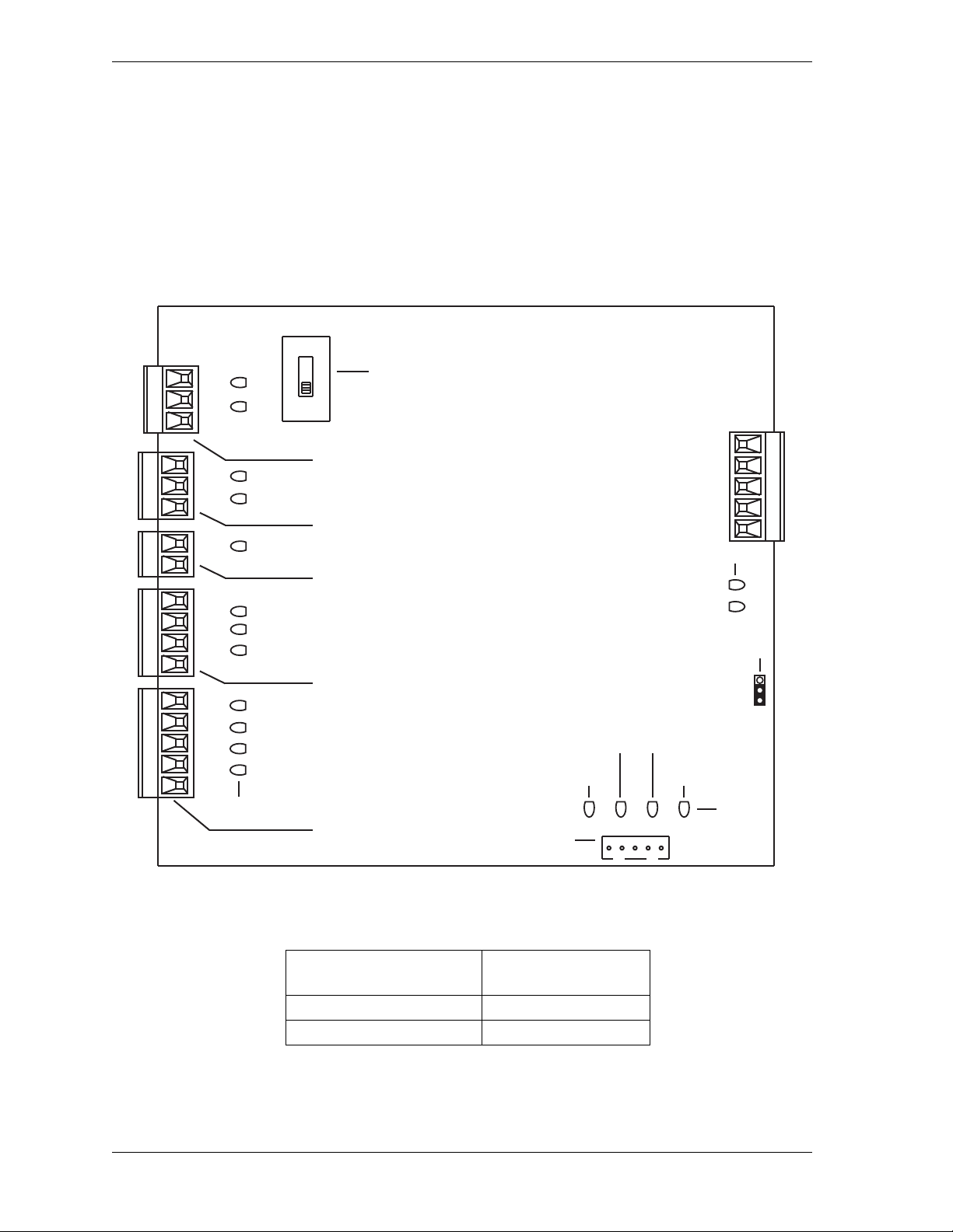
1128500 WPC 2000 User Manual
Stroke select
TB 701
Micro-inch/Set auxiliary cams
TB 705
Set cams switch
S701
Operator station select
TB 704
Automatic single-stroke or
Continuous on-demand
TB 703
Mode select
TB 702
Display cable
TB 706
Reset/Select
button/WPC Settings
key switch J 707
LEDs
DS750
DS755
DS749
DS762
DS748
DS760
DS761
DS747
DS759
DS754
DS753
DS752
SET CAMS
NORMAL
Jumper JP 720
(Must be on Run setting)
Monitor
Run
149148147146 151150 154153152
157156155
162161160159158
145144143142141
WPC Settings key
switch up (+) DS751
Reset/Select
button on DS757
Spare DS756
WPC Settings key
switch down (-) DS758
LEDs
Transmit DS764
Receive DS763
Display cable LEDs
Micro-inch can be wired to be permanently enabled or to be switched on and off.
To wire Micro-inch so that it is permanently enabled, install a jumper between pins #157 and
#155 (Ground) on TB705 on the WPC 2000 Display board (see Figure 2-16 and Table 2-23,
page 2-63).
To wire Micro-inch so that it can be turned on and off, wire a switch to pins #157 and #155 on
TB705 as shown in Table 2-7, below, and Figure 5 at the end of the manual. An optional
Micro-inch On/Off switch is available from Wintriss (see page 1-2).
To set the Micro-inch time, refer to Setting Micro-Inch, page 3-25.
Figure 2-16. WPC 2000 Display Board: Location of Important Components
2-34 Installation
Table 2-7. Micro-inch Wiring Connections
Display Board TB705
Pin # Signal
157 Micro-inch input
155 Ground
Page 62

WPC 2000 User Manual 1128500
DANGER
!
Disabling Top-stop in Inch
By default, Inch mode is set so that the ram top-stops whenever the Run/Inch palm buttons on
the Operator Station are pressed and held continuously (see Top-stop in Inch, page 4-9). You
can disable this default setting, allowing the ram to continue cycling in Inch mode as long as
the Run/Inch buttons are depressed. To do so, connect pin #13 on the Main Processor board
to +24 Vdc. You can connect to any convenient terminal that supplies +24 Vdc, such as pin
#9. See Table 2-17, page 2-62. When pin #13 is connected to +24 Vdc, the “Top stop inch
disable” LED on the WPC 2000 Main Processor board is illuminated (see Figure 3-14,
page 3-37 or Figure 3-15, page 3-38).
Wiring a Remote Reset Switch
If you would like to be able to reset the WPC 2000 from a location remote from the enclosure,
the WPC 2000 Main Processor board provides a terminal (i.e., pin #70) for wiring a remote
Reset switch (see Table 2-8 and Figure 2 at the end of the manual). The remote Reset
terminal can be wired to other equipment (e.g., the remote Reset circuit on a SmartPAC 2), or
you can use a simple switch to activate the Reset function.
To wire the remote Reset circuit, connect a wire from pin #70 to a normally open switch.
Connect another wire from the switch to a ground terminal (e.g., pin #54). WPC 2000 is reset
with a momentary connection to ground.
Table 2-8. Remote Reset Switch Wiring Connections
Main Processor Board
Pin # Signal
70 Remote Reset input
54 Ground
Installing 4-channel Programmable Cam
NON-SAFETY OUTPUTS USED FOR SAFETY FUNCTIONS
Use cams for non-safety functions only, such as convenience in automation. They cannot protect
personnel from a moving hazard.
Failure to comply with these instructions will result in death or serious injury.
You connect the cam channels from TB 109 on the WPC 2000 Main Processor board (see
Figure 2-12, page 2-23 or Figure 2-13, page 2-24) to the cam output assembly, which contains
the output relay modules that control the timing signals for your connected equi pment. These
relays open and close circuits to your equipment at the crankshaft angles you program (see
Setting Programmable Cams, page 3-33).
Installation 2-35
Page 63

1128500 WPC 2000 User Manual
CAUTION
Mounting and Wiring the Cam Output Assembly
The cam output assembly can be ordered in an enclosure or as a PC board. To mount and wire
either option, do the following:
BOARD DAMAGE OR SHORT CIRCUIT WHEN MOUNTED WITHOUT ENCLOSURE
• Mount the cam output assembly in a clean area where it will be safe from damage.
• Provide at least 0.5 in. (12.7 mm) clearance between the back of the board and any metal
surface.
Failure to comply with these instructions could result in property damage.
1. Select a convenient location for mounting the cam output assembly, choosing one that
allows you to easily run conduit from WPC 2000 to the cam outputs. You do not need to
access the cam outputs once they are installed and wired.
2. Mount the cam output assembly, referring to Figure 2-17 or Figure 2-18, page 2-37 for
mounting dimensions. Use the holes on the flanges to mount the cam output enclosure or
the corner holes to mount the cam output board.
3. The relays that will control your equipment should already be plugged into the cam output
board. If you need to replace a relay, simply pull the device out of its socket. Before
installing a relay , make sure that all the pins match the socket holes so you do not bend the
pins; then, press the relay in firmly.
4. Locate the twelve-conductor shielded cable that connects the WPC 2000 Main Processor
board to the cam outputs, and terminate the shield at each end near the entry point to the
enclosure or console (see Terminating Cable Shields, page 2-5).
5. Remove the TB109 connector from the WPC 2000 Main Processor board, and attach the
wires at one end of the cable to the terminals shown in Table 2-9, page 2-38 and Figure 6
at the end of the manual. Plug each connector back into its socket when you are finished.
2-36 Installation
Page 64
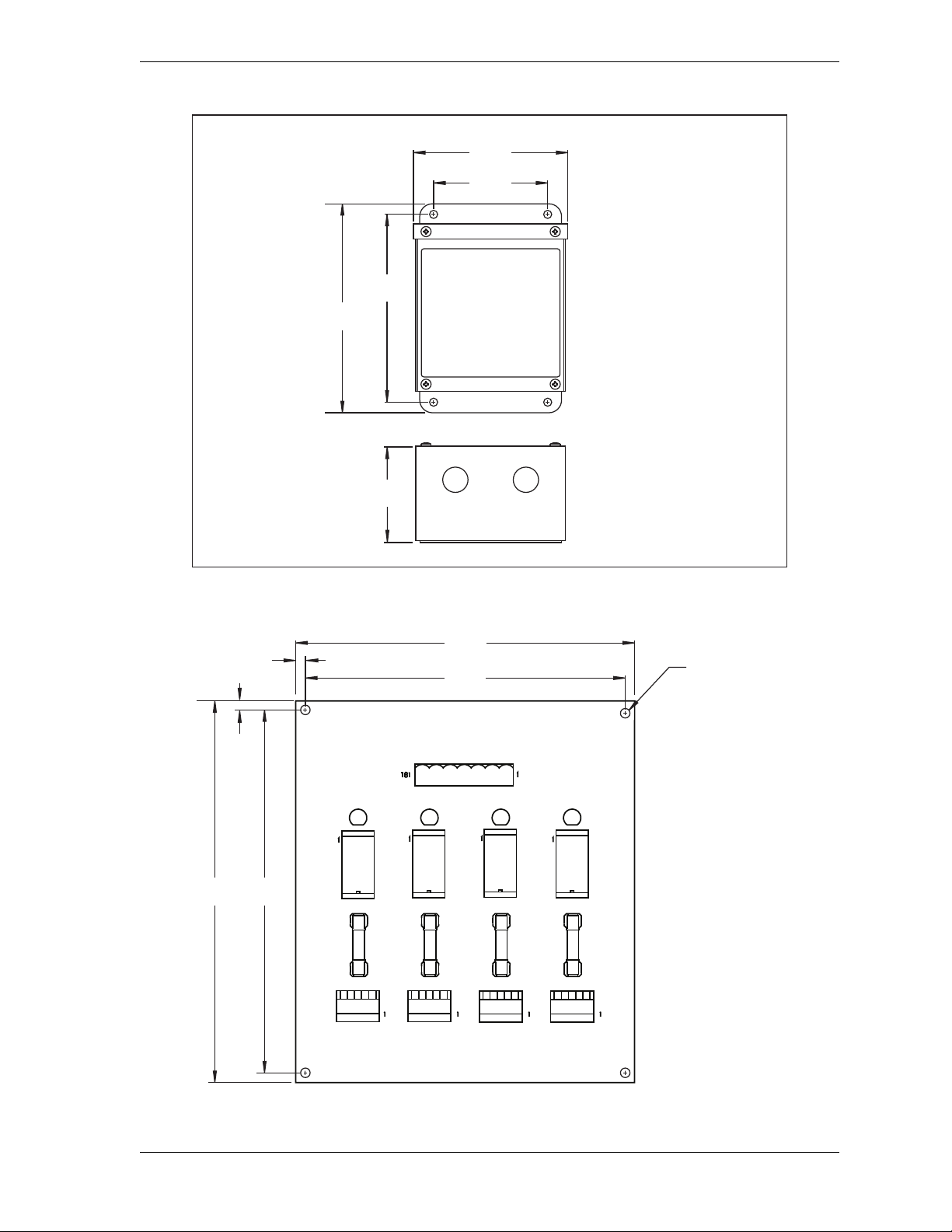
WPC 2000 User Manual 1128500
4.00
(101.6)
5.41
(137.4)
6.62
(168.1)
7.38
(187.5)
Dimensions: inches
(mm)
3.48
(88.4)
DS1 DS2 DS3 DS4
K1
F1
K2
F2
K3
F3
K4
F4
N/O
C
N/C
N/O
C
N/C
N/O
C
N/C
N/O
C
N/C
CHAN 1 CHAN 2
TB3TB2
CHAN 3 CHAN 4
TB4 TB5
CHASSIS
+24V
GND
CH 3
CH 2
CH 1
CH 4
5A 125 VAC
SLO-BLO
5A 125 VAC
SLO-BLO
5A 125 VAC
SLO-BLO
5A 125 VAC
SLO-BLO
4.35
(110.5)
4.75
(120.7)
5.50
(139.7)
5.10
(129.5)
0.20 (5.1) TYP
0.20
(5.1)
TYP
clearance hole
for #6 screw
4 PLACES
Dimensions: inches
(mm)
Figure 2-17. Cam Output Enclosure: Mounting Dimensions
Figure 2-18. Cam Output Board: Mounting Dimensions
Installation 2-37
Page 65
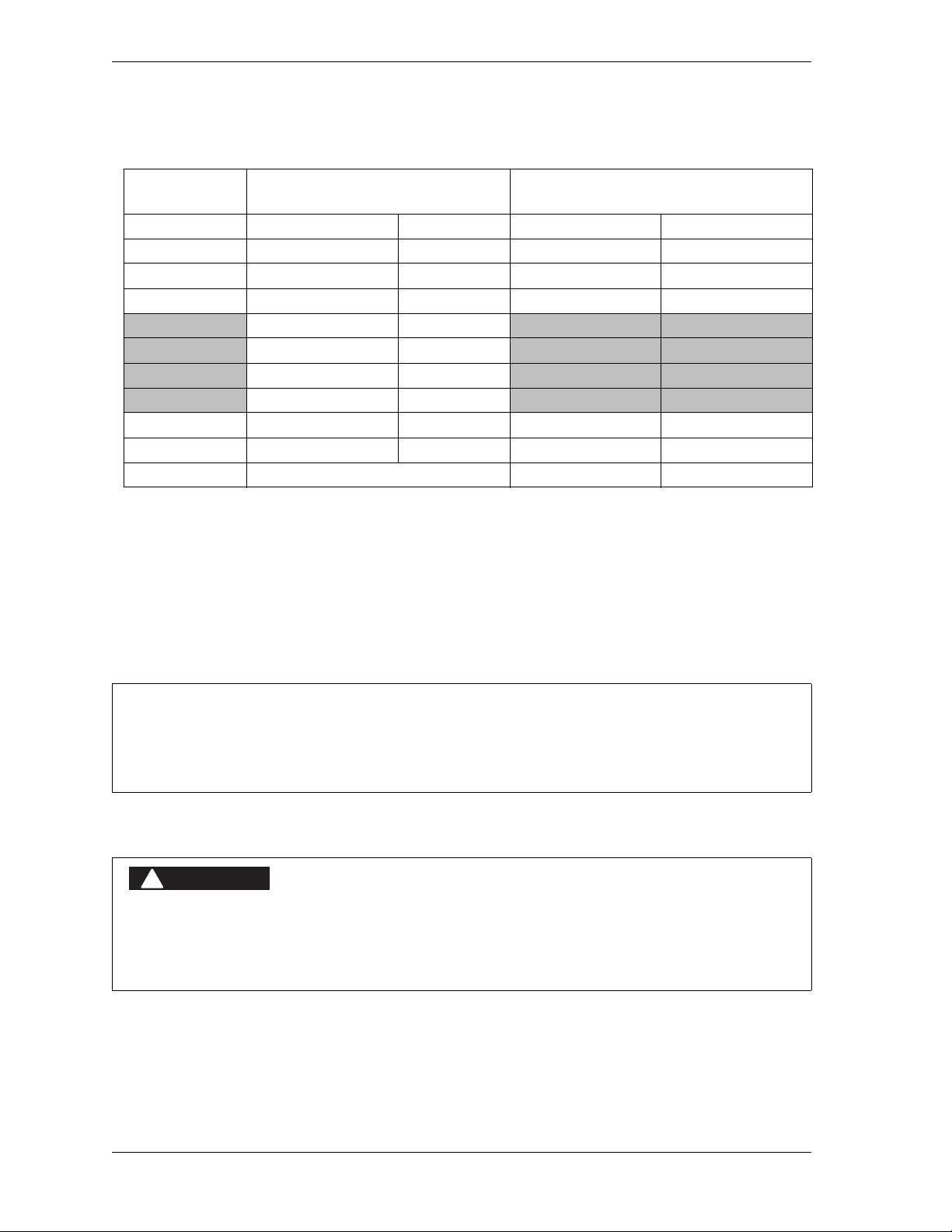
1128500 WPC 2000 User Manual
NOTICE
DANGER
!
Table 2-9. WPC 2000 Main Processor Board (TB109) to Cam Output Assembly (TB1):
Wiring Connections
WPC 2000 Main Proc. Board
Wire Color
Brown 130 Cam 1 7 Channel 1
Violet 129 Cam 2 6 Channel 2
Orange 128 Cam 3 5 Channel 3
Yellow 127 Cam 4 4 Channel 4
Black 122 Ground 3 Ground
Red 121 +24 Vdc 2 +24 Vdc
Shield Terminate drain wire to ground stud 1 Chassis
Pin # Signal
126 Counter
125 Zero Cam
124 Spec 1
123 Spec 2
4-channel Cam I/O Assembly (TB1)
Pin # Signal
6. Run the twelve-conductor cable through flexible, liquid-tight conduit to the terminal
points at the cam output assembly. You can use the knockouts directly below the
connectors if you have the cam output enclosure.
7. Remove the TB1 connector from the Cam Output board, and attach the wires at the other
end of the cable to the terminals shown in Table 2-9 and Figure 6. If you ordered the
enclosure, a wire from the CHAS terminal (pin #1) to a lug on the enclosure should
already be connected. Plug the connector back into its socket when you are finished.
TRIM UNUSED WIRES
If your installation does not require all the wires in the cable to be used, trim the unused wires,
cutting them flush with the ends of the cable jacket.
Making Wiring Connections to Cam Relays
NON-SAFETY OUTPUTS USED FOR SAFETY FUNCTIONS
Use cams for non-safety functions only, such as convenience in automation. They cannot protect
personnel from a moving hazard.
Failure to comply with these instructions will result in death or serious injury.
To connect the cam relays on the Cam Output board to your equipment, do the following:
2-38 Installation
Page 66
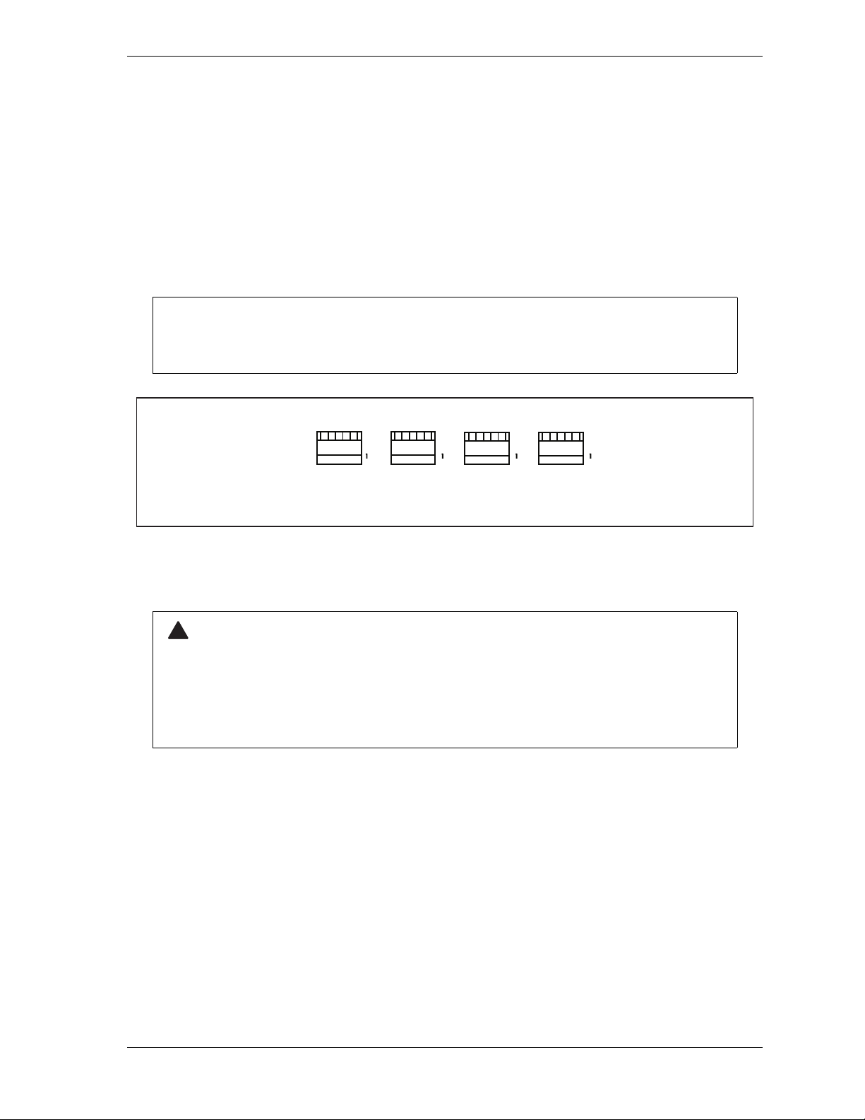
WPC 2000 User Manual 1128500
NOTICE
N/O
C
N/C
N/O
C
N/C
N/O
C
N/C
N/O
C
N/C
CHAN 1 CHAN 2
TB3TB2
CHAN 3 CHAN 4
TB4 TB5
WARNING
!
1. Remove the TB2 through TB5 connectors (for cam channel 1 through cam channel 4)
from the cam output board and wire them as follows, referring to Figure 2-19:
• Connect one wire to the terminal labelled “C”
• Connect the other wire to the terminal labelled “N/O” if you want your equipment to be
“on” during the cam angle interval set in WPC 2000
or
Connect the other wire to the terminal labelled “N/C” if you want your equipment to be
“on” except during the cam angle interval set in WPC 2000
Generally, you use the N/O terminal so that equipment is “off” except when you use WPC
2000 to turn it “on.” Use the N/C terminal only if it is more practical to do the reverse.
Figure 2-19. Connectors TB2 through TB5 on Cam Output Board
2. Plug TB2 through TB5 back into the Cam Output board.
SUPPRESSORS INSTALLED ACROSS RELAY CONTACTS
DO NOT install suppressors across the relay contacts in the cam output assembly. If a
suppressor is installed across the relay contacts and the relay fails shorted, the equipment
controlled by that relay will remain energized.
Failure to comply with these instructions could result in death or serious injury.
3. To reduce electrical noise and extend the life of the relays, do the following:
a. Install arc suppressors across each inductive AC load (motors, coils, etc.) that is
connected to a cam relay. Suppressors are supplied with your WPC 2000 cam outputs.
Install the suppressors across the load or as close to the load as possible. Attach
suppressors by connecting leads across existing terminals or junction points.
Figure 2-20, page 2-40 shows the correct way to install suppressors.
b. Install a diode across each DC load, such as relays, solenoids and PLC inputs, as
shown in Figure 2-21, page 2-40.
Installation 2-39
Page 67
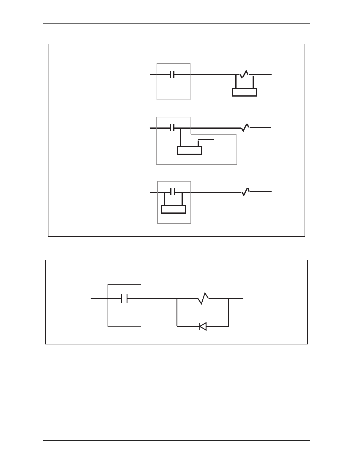
1128500 WPC 2000 User Manual
RIGHT
WRONG
ACCEPTABLE
not recommended
c n/o
Power
in
Power
Return
Suppressor
Relay
c n/o
Power
in
Suppressor
Power
Return
Power
Return
Relay
c n/o
Power
in
Suppressor
Power
Return
Relay
+ DC IN
DC RETURN
Relay
C N/O
IN4001 or equivalent
Enabling Cam Adjustments
You can enable adjustments to cam angles in three ways:
• Moving switch S701 on the WPC 2000 Display Board to its Up position
• Moving switch 1 on switch block S102 on the WPC 2000 Main Processor board to ON
• Wiring a key switch
Figure 2-20. Installing a Suppressor across an AC Load
Figure 2-21. Installing a Diode across a DC Load
2-40 Installation
Page 68
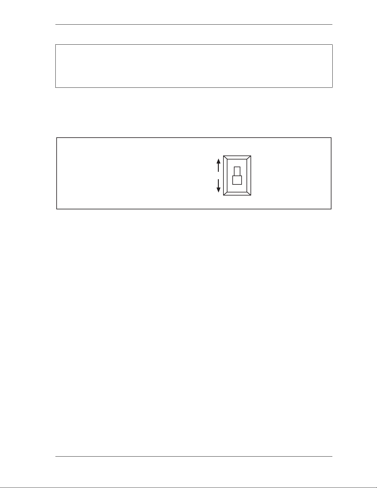
WPC 2000 User Manual 1128500
NOTICE
S701
DOWN position: Normal operation
UP position: Enable cam adjustments
ENABLING CAM ADJUSTMENTS
You should enable cam adjustments only when you are actually ready to set the cams. Otherwise,
you will not be able to adjust Top-stop Angle, Auto Carry-up Angle, etc.
Setting Switch S701 on the Displ ay B oar d
You enable the Set Cams function on switch S701 (see Figure 2-16, page 2-34 for switch
location) by moving the switch to its Up position, as shown in Figure 2-22.
Figure 2-22. “Set Cams” Switch (S701) Positions
Setting Switch 1 on S102 on the Main Processor Board
You can also enable the Set Cams function by setting switch 1 on switch block S102 on the
Main Processor board (see Figure 2-12, page 2-23 or Figure 2-13, page 2-24 for location) to
its ON (or Up) position. (See Making Settings on Switch Block S102, page 3-31 for further
details.) Using this switch may be preferable if the Display board is difficult to access.
Wiring a Remote Switch
You can also enable the Set Cams function by wiring your own two-position switch and
turning the function On and Off remotely. Wire the remote switch to pins #155 (Ground) and
#156 (Prog. Cams) on the WPC 2000 Display board, referring to Figure 2-16, page 2-34 and
Figure 5 at the end of the manual. If you opt to use a remote switch to enable cam settings,
make sure that switch S701 is in the Down position.
Installation 2-41
Page 69
1128500 WPC 2000 User Manual
DANGER
!
DANGER
!
Wiring Zero Cam Output to AutoSet
WPC 2000 provides a zero cam output that automatically turns on at 270° and turns off at 30 °
on every stroke. You can wire this output to AutoSet 1500 and 1504 load analyzers, as shown
in Table 2-10, below, and Figure 6 at the end of the manual.
Table 2-10. Zero Cam Output Wiring Connections
WPC 2000 Main Processor Board
(TB 109)
Pin # Signal
pin # 125 Zero Cam Output pin # 2 Zero Cam
AutoSet 1500 (TB101B)
or 1504 (TB101A)
Pin# Signal
Wiring a Foot Switch
UNGUARDED HAZARDS
When using a foot switch, ensure that light curtains and other safeguards are properly installed
and operating to protect operators.
Failure to comply with these instructions will result in death or serious injury.
IMPROPER FOOT SWITCH
Ensure that any foot control switch complies with OSHA 1910.217 (b) (7) (x), including protection
from accidental actuation by falling or moving objects or unintentional stepping on the control.
Failure to comply with these instructions will result in death or serious injury.
Foot Switch, an option available from Wintriss, enables the operator to use both hands during
operation of the press as, for example, when manually feeding parts. If you choose to order a
foot switch, you must obtain optional One-hand/Two-hand/Foot firmware from Wintriss and
install a Shadow safety light curtain.
Wire the Foot Switch’s normally closed contact to pin #4 on the WPC 2000 Main Processor
board and the normally open contact to pin #14, then wire both contacts to +24 Vdc, as shown
in Table 2-11, below, and Figure 2 at the end of the manual.
Table 2-11. Foot Switch Wiring Connections
WPC 2000 Main Processor Board
Pin #
4 N/C input
14 N/O input
+24 Vdc (e.g., #37) Common
Foot Switch
Contacts
Refer to page 3-27 for Foot Switch settings.
2-42 Installation
Page 70

WPC 2000 User Manual 1128500
DANGER
!
DANGER
!
Instal lin g a One-hand Control
INSTALL SAFEGUARDS TO PREVENT ACCESS TO HAZARDOUS AREA
• Follow all applicable OSHA and ANSI regulations for safeguarding your press system. Point-ofoperation safeguarding is the single most important factor in the prevention of injuries.
• Follow all applicable OSHA and ANSI regulations when installing a one-hand control.
• Ensure that proper safeguarding devices are installed and working properly. Wintriss takes no
responsibility if safeguarding devices are not installed or working correctly.
• DO NOT use WPC 2000 or a one-hand control as a safeguarding device.
• Install and operate WPC 2000 and a one-hand control in accordance with OSHA and ANSI
regulations.
Failure to comply with these instructions will result in death or serious injury.
PREVENT OPERATOR FROM STANDING BETWEEN LIGHT CURTAIN AND HAZARD
Ensure that the operator cannot position himself between the light curtain and the hazardous area.
Use another pair of light curtains or a mechanical barrier at knee to waist height to prevent the
operator or a passerby from being “trapped” between the light curtain and the hazard.
Failure to comply with these instructions will result in death or serious injury.
One-hand Control is a switch available from Wintriss that allows operators to use their free
hand to feed a part while their other hand operates the switch. This option can only be used
with WPC 2000 systems equipped with One-hand and Single-stroke modes, employing a
Shadow light curtain to guard the point of operation, and running One-hand/Two-hand/Foot
firmware.
The One-hand Control is mounted on or near the press and allows the operator to cycle the
press without using the Operator Station. To stroke the press, the operator simply pushes the
button as part of his normal hand motion after loading a part.
The One-hand Control can be used in two different modes. In Normal mode, the press cycles
in Single-stroke whenever you push the One-hand Control button. In “Light Curtain Break”
mode, the press cycles only when you push the One-hand Control button within eight seconds
after removing your hand(s) from the light curtain. If the button is pushed after this interval
expires, the press does not cycle.
Light Curtain Break mode prevents inadvertent operation of the press when an operator is
loading or unloading parts.
The mode used for One-hand Control is determined by the setting on option switch 3 (see
Enabling Light Curtain Br eak Mode in a One-hand Control, page 3-27). When switch 3 is set
to OFF, One-hand Control operates in Normal mode. When switch 3 is set to ON, One-hand
Control operates in Light Curtain Break mode.
Installation 2-43
Page 71
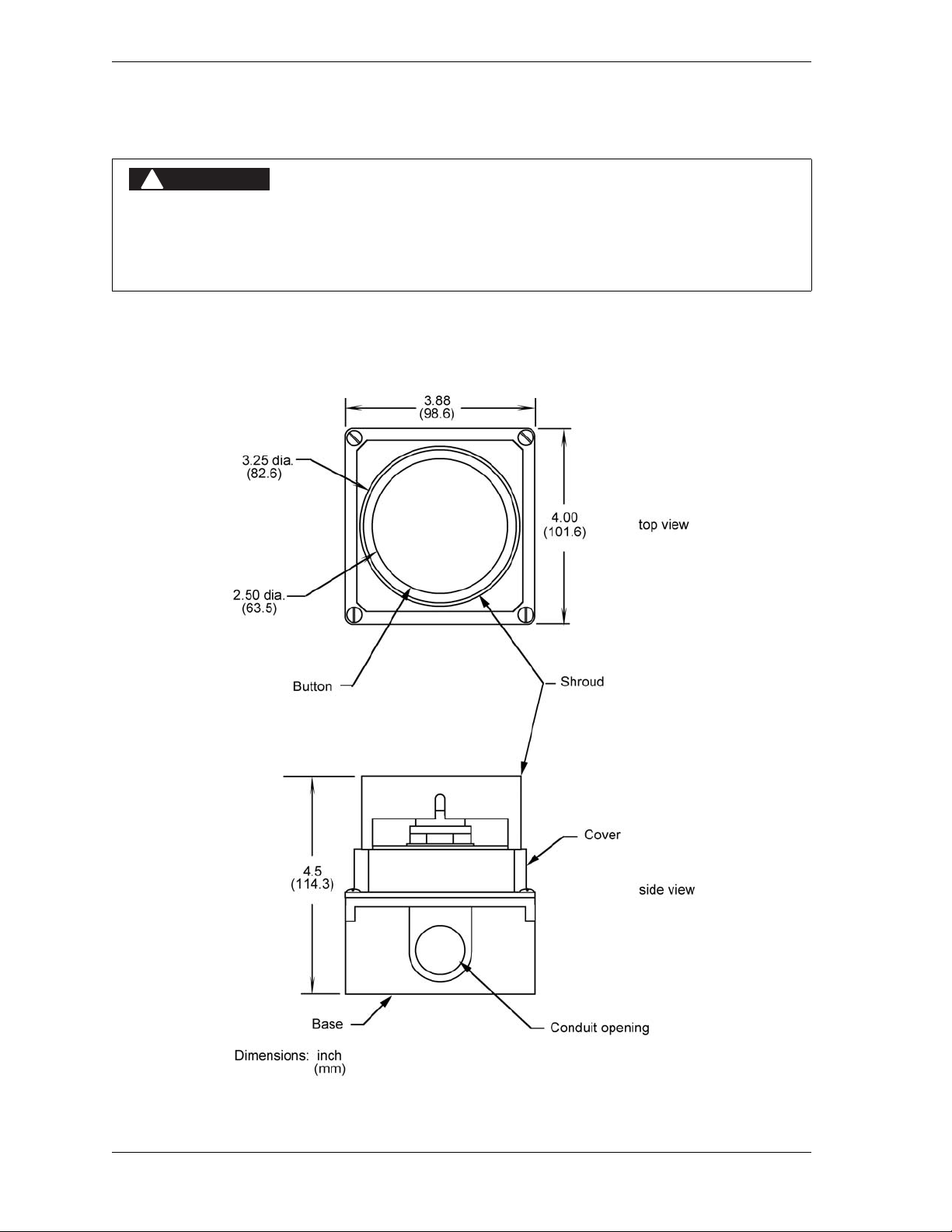
1128500 WPC 2000 User Manual
DANGER
!
Mounting a One-hand Control
DO NOT MOUNT OPERATOR CONTROL TOO CLOSE TO HAZARD
Mount the One-hand Control outside the area protected by the light curtain. DO NOT mount the
One-hand Control between the light curtain and the point of operation.
Failure to comply with these instructions will result in death or serious injury.
To mount the One-hand Control, perform the following steps, referring to Figure 2-23, below,
and Figure 2-24, page 2-45 for mounting dimensions:
Figure 2-23. One-hand Control Switch: Mounting Dimensions
2-44 Installation
Page 72
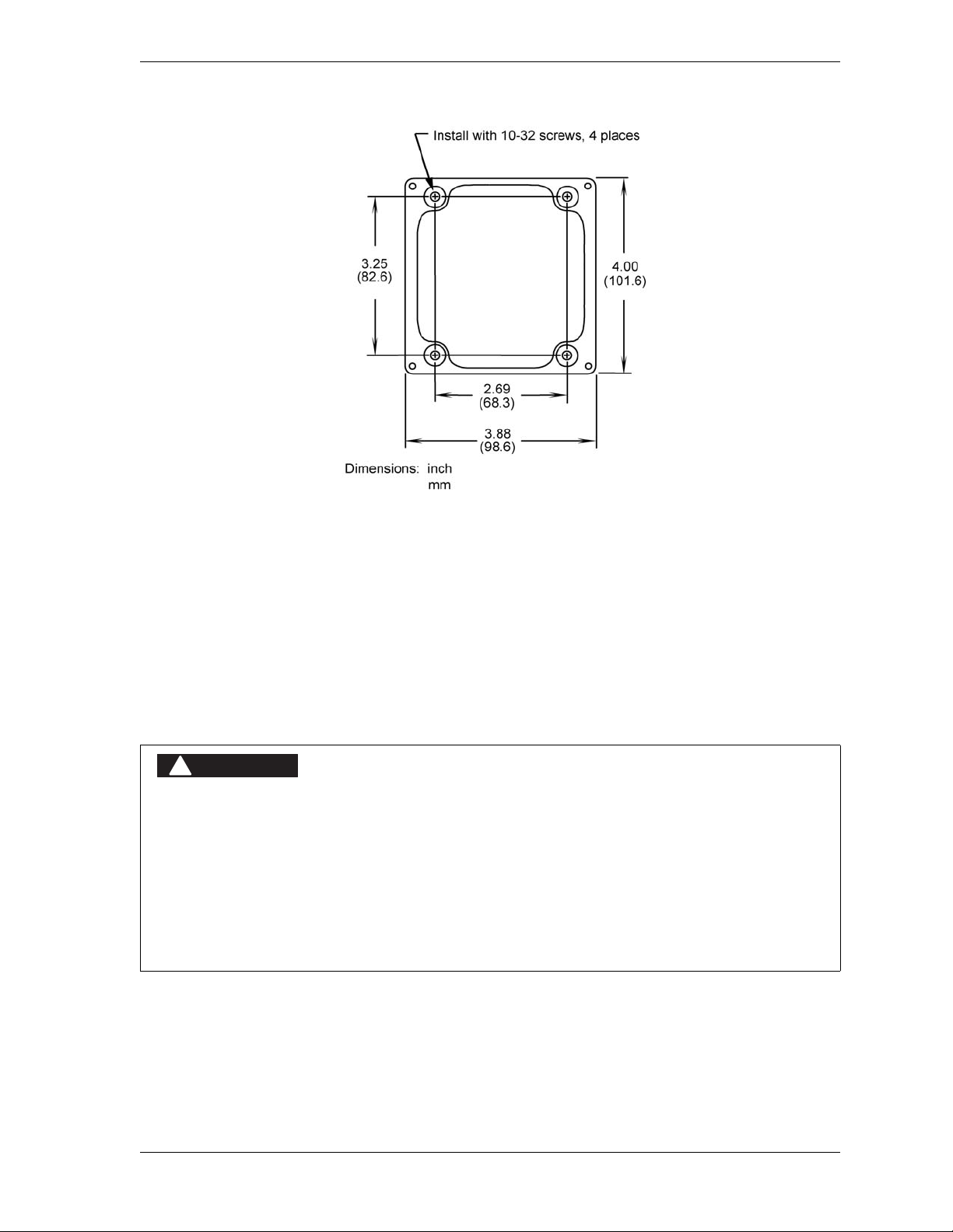
WPC 2000 User Manual 1128500
DANGER
!
Figure 2-24. One-hand Control Switch Base: Mounting Dimens ions
1. Shut off power to the press and to WPC 2000.
2. Choose a mounting location on or near the press convenient to the operator. The
One-hand Control should be mounted so the operator can reach it as part of normal hand
movement after loading a part. An adjustable bracket may be necessary.
3. Mount the One-hand Control, using the tapped holes on the bottom of its metal enclosure.
Wiring a One-hand Control to WPC 2000
ELECTRIC SHOCK OR HAZARDOUS ENERGY
• Disc onn ec t main powe r before install atio n.
• Remove all power to the press, press control, and other equipment used with the press.
• Remove all fuses and “tag out” per OSHA 1910.147 Control of Hazardous Energy (Lockout/
Tagout).
• Ensure that installation is performed by qualified personnel.
• Complete all installation procedures before connecting to the AC power source.
Failure to comply with these instructions will result in death or serious injury.
To wire One-hand Control, you need to make connections to both the Operator Station and to
the WPC 2000 Main Processor board. To do so, perform the following steps:
1. Turn off power to the press and to the WPC 2000.
Installation 2-45
Page 73
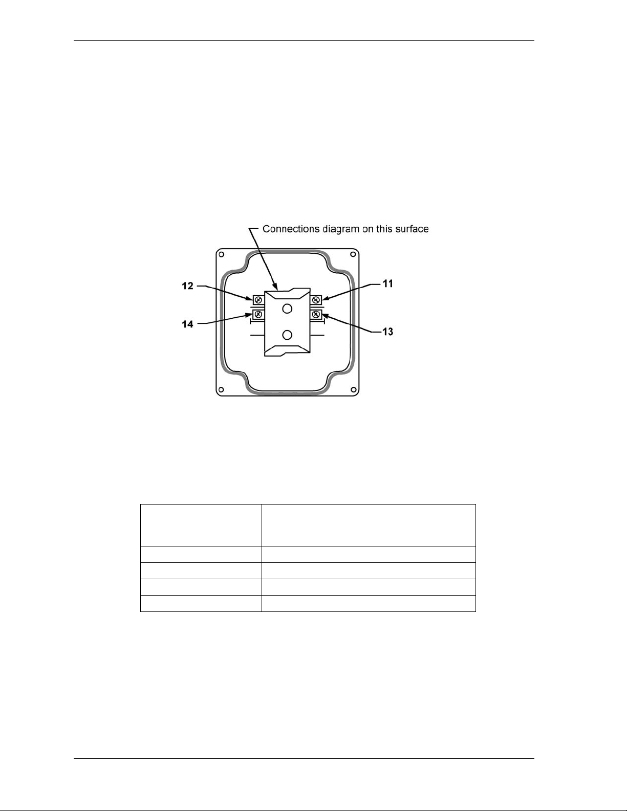
1128500 WPC 2000 User Manual
2. Loosen the clips at the bottom of the front panel of the Operator Station. Swing the front
panel up and support it so you can work inside the box. (The cover will stay up if you
slide it slightly to the left or right.)
3. Knock out a hole in the bottom of the Operator Station near the existing conduit from the
WPC 2000 control enclosure.
4. Using the conduit hole provided in the base of the One-hand Control, run conduit and
wiring to the Operator Station, referring to Figure 2-25 for terminal locations on the
bottom of the One-hand Control.
Figure 2-25. Wiring Connections in One-hand Control Switch (Switch Cover, Bottom View)
5. Measure wires to fit before cutting, then make the appropriate wiring connections,
referring to Table 2-12, below, and Figure 8 at the end of the manual.
Table 2-12. One-hand Control Wiring Connections
WPC 2000 Main Processor Board and
One-hand Control
Terminal # *
11 1 Palm switch A N/C input +
12 Blue wire in Operator Station cable
13 3 One-hand A input +
14 Blue wire in Operator Station cable
* Refer to Figure 2-25, above
6. Fasten the switch cover onto the base with the screws provided.
7. Tighten all conduit connections that may have been loosened during installation.
8. Close and latch the cover of the Operator Station and WPC 2000.
9. Make sure that you have run all your ground wires. Do not use conduit as ground.
Operation St ation Connections
Pin# Signal
2-46 Installation
Page 74
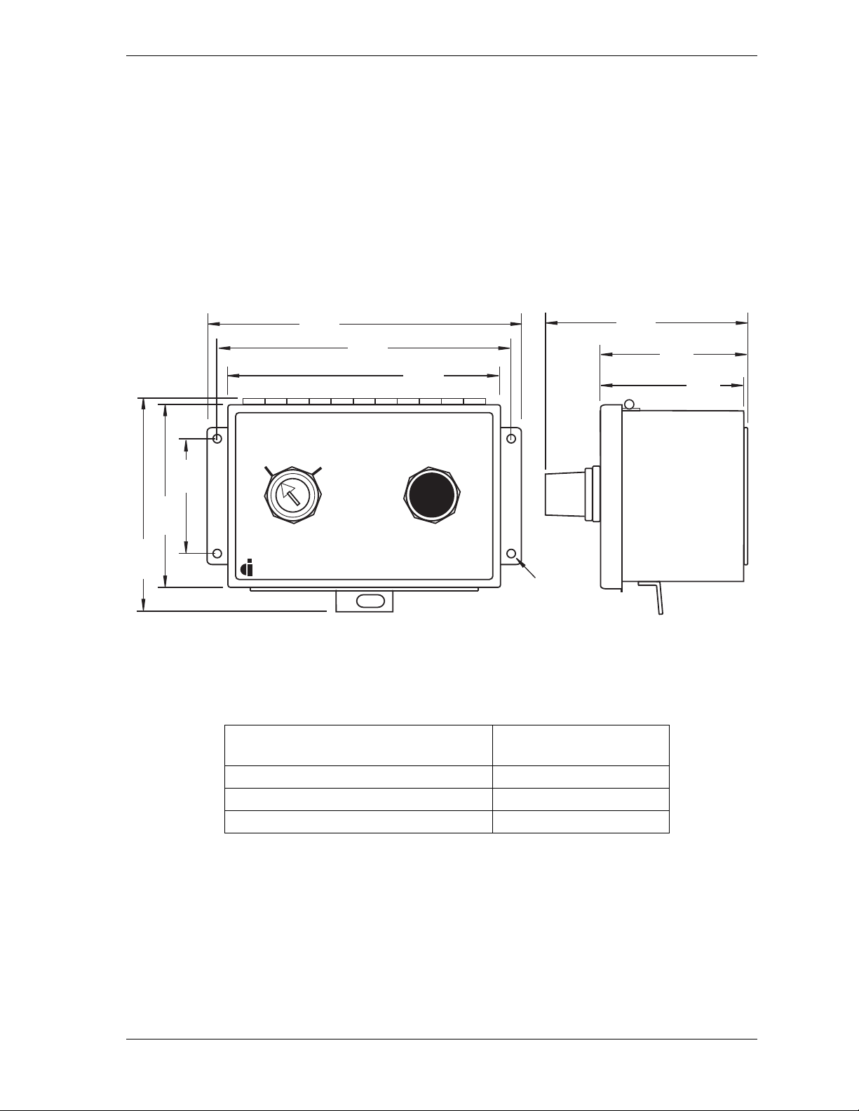
WPC 2000 User Manual 1128500
BAR CONTROL
OPERATESELECT
OFF ON
DATA INSTRUMENTS
Wintriss Controls Group
6.23
(158.2)
7.49
(190.2)
3.13
(79.5)
3.24
(82.3)
4.60
(116.8)
5.02
(127.5)
6.70
(170.2)
0.312
(7.9)
4 places
2.00
(50.8)
4.40
(111.8)
Dimensions: inches
(mm)
Mounting and Wiring the Bar Control Enclosure
Mount the Bar Control enclosure in a location that is convenient to the operator while he is
releasing the machine’s brake and barring the press. Make sure that the operator will not
block a light curtain while pressing the Bar control Operate button. Refer to Figure 2-26 for
mounting dimensions.
To wire the Bar Control, connect the Bar selector switch input to pin #6 on the WPC 2000
Main Processor board and the Bar actuator input to pin #16, as shown in Table 2-13 and
Figure 2 at the end of the manual.
Figure 2-26. Bar Control Enclosure: Mounti ng Dimensi ons
Table 2-13. Bar Control Wiring Connections
WPC 2000 Main Processor Board
Bar Control Contacts
Pin #
16 Bar actuator input
6 Bar selector switch input
+24 Vdc (e.g., #37) Common
Installation 2-47
Page 75

1128500 WPC 2000 User Manual
DANGER
!
DANGER
!
Wiring Automatic Single-stroke
PRESS STARTING UNEXPECTEDLY
• Ensure that light curtains and other safeguards are properly installed and operating to protect
operators when using Automatic Single-stroke. Since the external trigger starts the stroke, a
stroke can occur unexpectedly.
• Ensure that guarding is properly installed to prevent access to the machine over, under, or
around any guarding device.
Failure to comply with these instructions will result in death or serious injury.
Automatic Single-stroke is an operating mode that enables the operator to automate a manual
press using a feeding device or robot. To wire the switch that turns on this feature, refer to
Figure 5 at the back of the manual. To wire the Automatic Single-stroke actuating
mechanism, refer to Table 2-14 and Figure 2 at the back of the manual.
Table 2-14. Automatic Single-stroke Wiring Connections
WPC 2000 Main Processor Board
Pin #
15 N/C input
5N/O input
+24 Vdc (e.g., #37) Common
Foot Switch
Contacts
Though an SPDT contact is shown in Figure 2, you can also use solid state switches
(proximity switches, for example) or outputs from a programmable logic controller (PLC).
To make sure that the contacts are clear and reliable, the switch or relay should be new and
unused.
You set the wait time for Automatic Single-stroke with option switch 5 (see page 3-29). To
operate the press in this operating mode, refer to page 4-16.
Wiring Automatic Continuous On-demand
PRESS STARTING UNEXPECTEDLY
• Ensure that light curtains and other safeguards are properly installed and operating to protect
operators when using Automatic Continuous On-demand mode, in which a stroke can occur
unexpectedly.
• Ensure that guarding is properly installed to prevent access to the machine over, under, or
around any guarding device.
Failure to comply with these instructions will result in death or serious injury.
Contact Wintriss Tech. Support for information on using this operating mode.
2-48 Installation
Page 76

WPC 2000 User Manual 1128500
DANGER
!
DANGER
!
CAUTION
Installing Revised Firmware in WPC 2000
MACHINE MALFUNCTION AFTER INSTALLING REVISED SOFTWARE
Perform the installation verification (see page 2-58) and final checkout (see page 3-35) tests after
performing the firmware installation.
Failure to comply with these instructions could result in death or serious injury.
ELECTRIC SHOCK OR HAZARDOUS ENERGY
• Disc onn ec t main powe r before install atio n.
• Remove all power to the press, press control, and other equipment used with the press.
• Remove all fuses and “tag out” per OSHA 1910.147 Control of Hazardous Energy (Lockout/
Tagout).
• Ensure that installation is performed by qualified personnel.
• Complete all installation procedures before connecting to the AC power source.
Failure to comply with these instructions will result in death or serious injury.
To install revised firmware in WPC 2000, follow these steps:
1. Record the following WPC 2000 settings, referring to Viewing and Setting Press
Parameters, page 3-1 for help in displaying them in the digital LED readout:
• Stop-time Limit
• Auto Carry-up Angle
• Top-stop Angle
• Micro-inch time
• Cam On/Off settings
• Counter Preset
• Counter (if necessary)
2. Turn off power to WPC 2000. The LED display and crank-angle clock should go blank.
STATIC DISCHARGE DAMAGE TO CHIP
Ground yourself before touching circuit boards or chips by touching a large metal object
such as the press. Static electricity can destroy electronic components.
Failure to comply with these instructions could result in property damage.
3. Making sure that you are grounded, open the WPC 2000 enclosure and locate firmware
chips A (labelled “U111”) and B (labelled “U134”) on the Main Processor board (see
Figure 2-12, page 2-23 or Figure 2-13, page 2-24). Note that each chip has a white label
and a semi-circular notch at one end. The notch on the chip faces in the same direction as
the notch on its socket.
Installation 2-49
Page 77

1128500 WPC 2000 User Manual
NOTICE
CAUTION
CAUTION
NOTICE
Each new WPC 2000 firmware chip must be installed with the notch facing in the same
direction as the chip it is replacing.
If you use a screwdriver, be careful not to insert the screwdriver under the socket or you
may damage the board.
Failure to comply with these instructions could result in property damage.
4. Use a chip puller to remove the old chips, or insert a small screwdriver between the
bottom of the chips and their sockets and carefully pry the chips from the board. Put the
chips aside.
5. Making sure you are grounded, open the package containing the new firmware chips, and,
one at a time, remove the chips from their holders.
CHIP INSTALLED INCORRECTLY
• Install each chip with the notch facing in the same direction as the notch on the old
firmware chip; otherwise, when you power up the control, the chips will be destroyed.
• Align pins correctly with the socket before plugging chips in.
Failure to comply with these instructions could result in property damage.
6. Plug each chip into its socket, inserting the left row of pins first, then aligning the right
row of pins over the socket and pushing them in. Make sure that the notch in the chip
faces in the same direction as the notch in the old chip and that all of the pins are in the
socket.
If the two rows of pins are spread too far apart to plug easily into the socket, hold the chip
on its side on a flat surface with the pins pointing toward you. Being careful not to
overbend the pins, gently draw the top of the chip toward you until the pins bend a little.
Turn the chip over so that the other row of pins is now flat and pointing toward you. Draw
the top of the chip toward you again until the pins bend. When the rows of pins look
parallel, plug the chip into its socket again. If the chip still doesn't fit, repeat this procedure.
7. To verify that both chips are installed correctly, power up the WPC 2000.
• If the unit powers up normally (i.e., with “Loc” displayed in the LED readout), go to
step 8.
• If the unit powers up with “rolling” LEDs, or otherwise malfunctions, one or more pins
may be bent or not plugged in properly . Turn the power off, and repeat the procedure in
the Notice for step 6 for each chip. Power the unit up again. If WPC 2000 continues to
malfunction, call Wintriss Tech. Support.
2-50 Installation
Page 78

WPC 2000 User Manual 1128500
DANGER
!
8. Re-initialize the system, following the instructions starting on page page 3-3.
MAKE SURE THAT STOP TIME LIMIT IS CORRECT AFTER INITIALIZATION
Whenever you initialize WPC 2000, the Stop-time Limit is reset to its factory value of 500
mS. Make sure to set the Stop-time Limit to a value based on the actual stopping time of
your press. Use the stopping time measured in the 90º stop-time test to calculate the
safety distance.
Failure to comply with these instructions will result in death or serious injury.
9. Re-enter the settings you recorded in step 1.
10. Perform installation verification (see page 2-58) and final checkout (see page 3-35) tests.
Installing WPC 2000 without Enclosure
When you order WPC 2000 without enclosure, you receive a Main Processor board, power
supply, and input power terminal block mounted on an aluminum plate and either a panel
mount display or display board kit. First, install the mounting plate as instructed in the next
section, then mount the display according to instructions in Installing the Panel-mount
Display, page 2-52 or Installing Display Board Kit with Selector Switches, page 2-55.
Installing the WPC 2000 Mounting Plate
The mounting plate has a hole in each corner to facilitate mounting of the WPC 2000 Main
Processor board and related components in your enclosure or console. When installing the
mounting plate, refer to Figure 2-27, page 2-52 for mounting dimensions. Be sure to allow at
least 1 in. clearance on top, bottom, and both sides of the plate and above the power supply
and Main Processor board. Allow at least 2 1/2 in. clearance on the right side of the plate for
making wiring connections to terminal blocks TB101-TB104.
The power supply on the mounting plate is pre-wired to the power terminal, TB105, on the
Main Processor board and to the input power terminal block on the plate. To connect AC
wiring to the input power terminal block, follow the instructions in Connecting AC Wiring,
page 2-8.
Installation 2-51
Page 79
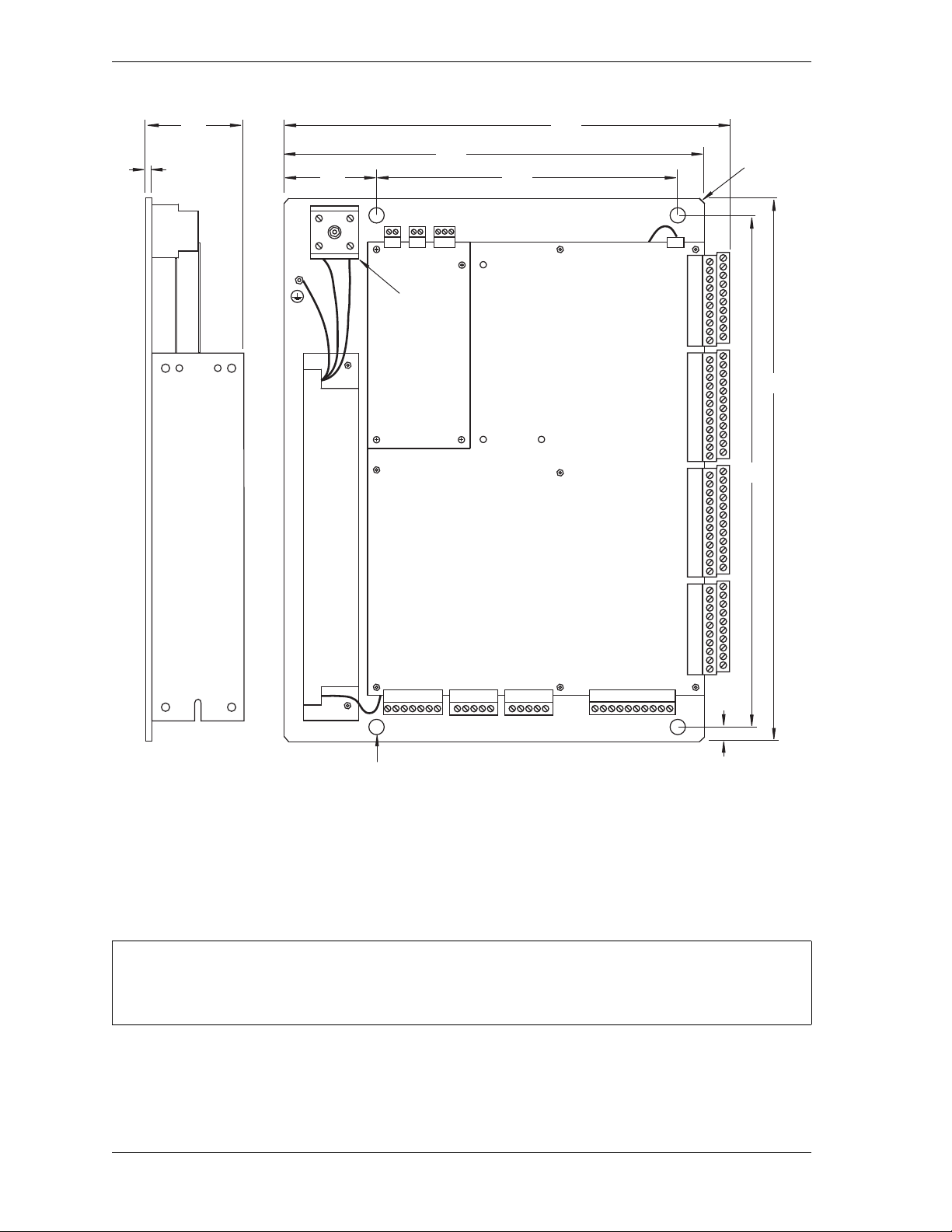
1128500 WPC 2000 User Manual
TB105
TB104TB103TB102TB101
TB 109
.312
(7.92)
ID
4 places
45
o
x .125
(3.18)
4 places
TB 106
Dimensions: inches
(mm)
Allow 1 clearance on top, bottom, and left side
of mounting plate and above board/power supply.
Allow 2 1/2 clearance on right side (i.e., side to
which TB101-TB104 are connected).
.090
(2.3)
TB 107 TB 108
Input power
terminal
block
.25
(6.4)
10.65
(270.5)
10.00
(254.0)
2.25
(57.1)
7.00
(177.8)
13.00
(330.2)
12.25
(311.2)
2.67
(67.8)
NOTICE
Figure 2-27. WPC 2000 Mounting Plate: Mounting Dimensions
Installing the Panel-mount Display
Mounting the Display
Install the panel mount display at a height convenient for all users. Experiment to determine a
good height for every user before mounting the display.
To install the panel-mount display in your enclosure or console, do the following, referring to
Figure 2-28, page 2-53 for mounting and cutout dimensions:
2-52 Installation
Page 80
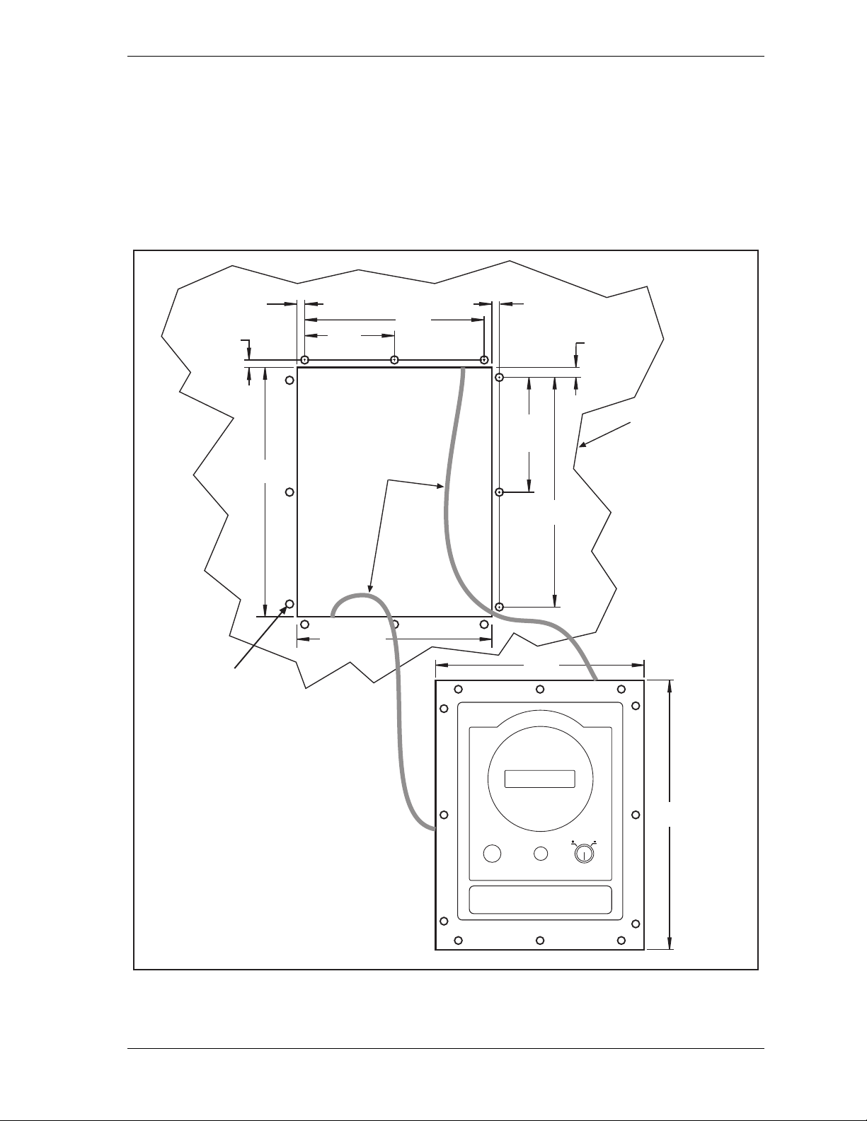
WPC 2000 User Manual 1128500
YOUR
PANEL
tapped or
clearance
holes for
No. 10
hardware
12 places
allow
9 in. (230 mm)
service
loop
allow at least
4 in. (100 mm)
clearance
behind panel
Dimensions:
inches (mm)
0.5 (12.7)
2 places
6.50 (165.1)
10.00
(254.0)
9.00
(228.6)
7.50
(190.5)
6.00
(152.4)
0.25 (6.4)
2 places
0.25 (6.4)
2 places
4.00
(101.6)
4 places
8.00
(203.2)
0.25 (6.4)
2 places
3.00
(76.2)
4 places
WPC SETTINGSRESET/SELECT MUTE
1. Determine a convenient location to mount the display panel and selector switches in your
enclosure or console. Mount the display so that operators and setup personnel can easily
see the readouts and reach the switches. Make sure that all switches are no more than one
ft. (300 mm) from the display.
2. Cut out a hole in your enclosure or console, and drill and tap twelve holes for #10-32
screws, referring to Figure 2-28.
Figure 2-28. WPC 2000 Panel Mount Display: Mounting and Cutout Dimensions
Installation 2-53
Page 81
1128500 WPC 2000 User Manual
NOTICE
DANGER
!
NOTICE
3. Prop the display panel near the location where you plan to mount it. You can do this by
connecting ty wraps from two of the left holes on the panel to the corresponding holes on
the enclosure or console, creating hinges. Allow 9 in. of service loop when performing the
wiring connections, and make sure all cables will reach the connectors.
Connecting the Panel-mount Display to the WPC 2000 Main Processor Board
Connect the display cable from TB706 on the Display board to TB108 on the Main Processor
board, referring to Table 2-15 and Figure 5 at the end of the manual for wiring connections.
CONNECT DISPLAY CABLE CORRECTLY
Make sure that the display cable is connected correctly at both ends. Connect the display
cable to TB706 on the Display board with the black wire closest to the small numeral 1
toward the bottom of the board. The black wire indicates pin #1.
Table 2-15. Display Cable Wiring Connections, Display Board to Main Processor Board
Display Board
TB706 Pin # Wire Color Signal
158 Red V+ 116
159 White CAN+ 1 17
160 SHIELD 118
161 Green CAN- 119
162 Black COM 120
Main Processor Board
TB108 Pin #
Installing Selector Switches and Final Assembly
DO NOT USE CONTINUOUS MODE ON PRESS WITHOUT PROPER GUARDING
Disconnect the “Continuous” position on the stroke selector switch and cover the “CONT” label on
your control if your press is not guarded properly for use in Continuous mode or you do not run
your press in Continuous mode.
Failure to comply with these instructions will result in death or serious injury.
Mount selector switches within 1 ft. (300 mm) of the Display board.
1. Select a mounting location for the selector switches. Switches must be mounted within 1
ft. (300 mm) of the display.
2-54 Installation
Page 82
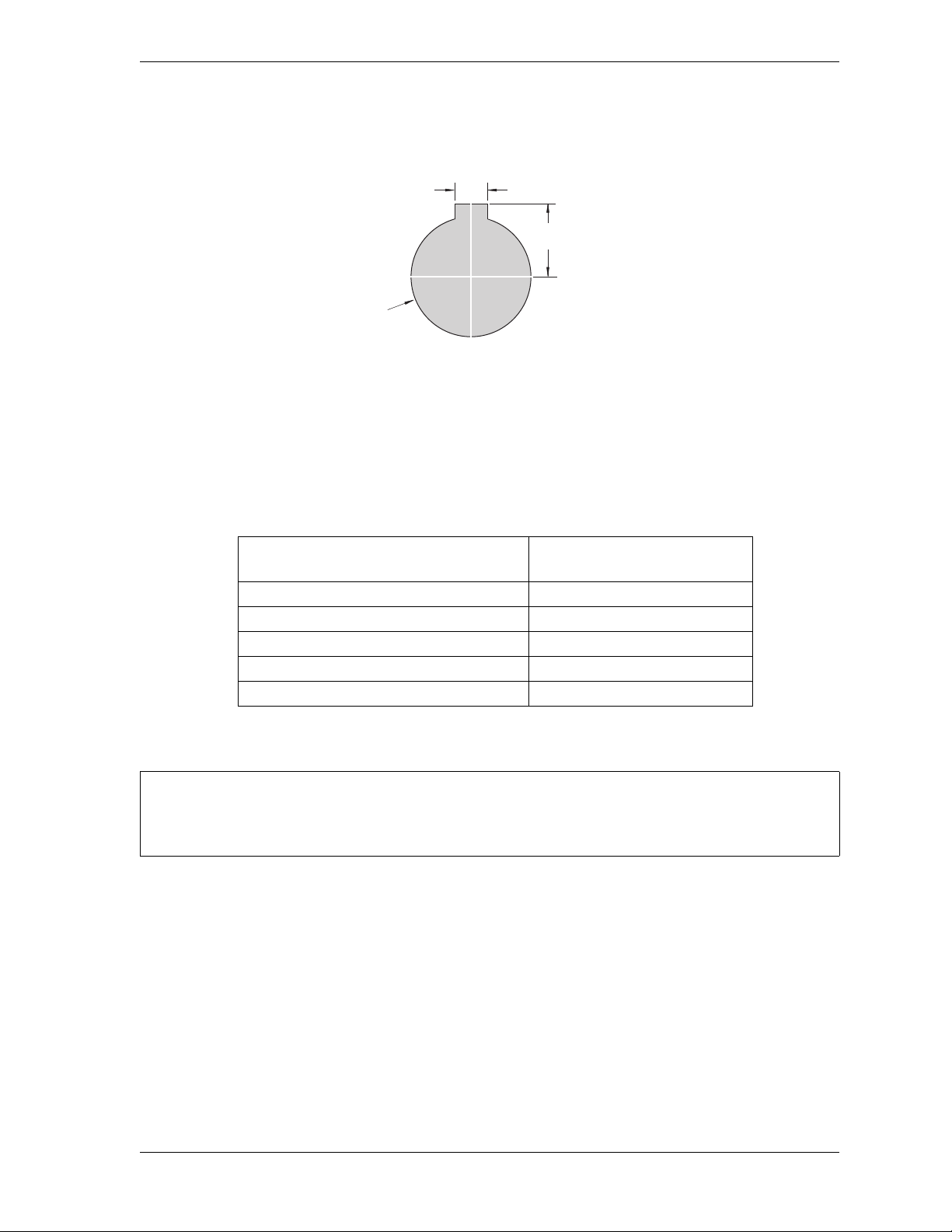
WPC 2000 User Manual 1128500
0.172
(4.37)
0.672
(17.1)
1.218 dia.
(30.9)
Dimensions:
inches (mm)
NOTICE
2. Cut holes in your enclosure or console for the selector switches, referring to Figure 2-29
for cutout dimensions. Dimensions are the same for all switches.
Figure 2-29. Selector Switch: Cutout Dimensions
3. Install the selector switches.
4. Wire each selector switch to the appropriate terminal block on the WPC 2000 Display
board, referring to Table 2-16 and Figure 5 at the back of the manual for wiring
connections
Table 2-16. Selector Switch Wiring Connections
Terminal Block on
Selector Switch
Stroke Select TB701
Mode Select TB702
Automatic Single-stroke (External Trip) TB703
Operator Station Select TB704
Micro Inch TB705
WPC 2000 Display Board
Installi ng Display Board Kit wi th Selector Switches
Install the panel mount display at a height convenient for all users. Experiment to determine a
good height for every user before mounting the display.
1. Make sure that your display board kit contains the following components:
• Label
• PC board
• Push button
• Mute lamp
• Key switch with wiring harness assembly
• Four standoffs
• Four lock nuts.
Installation 2-55
Page 83
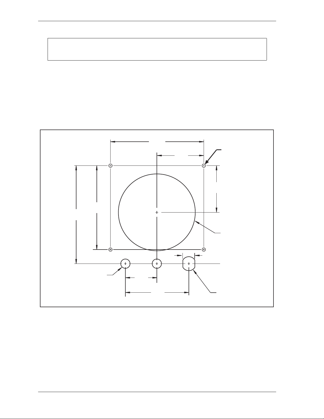
1128500 WPC 2000 User Manual
NOTICE
Dimensions:
inches (mm)
2.500
(63.5)
5.000
(127.0)
0.500 (12.7) DIA.
2 places
0.64 (16.3)
4.12
(104.6)
4.500
(114.3)
5.235
(133.0)
3.400
(86.4)
0.76 (19.3)
1.700
(43.2)
6-32 x 0.625 studs
(on far side)
4 places
2.500
(63.5)
DIA.
DIA.
Install selector switches within 1 ft. (300 mm) of the Display board.
2. Determine a convenient location to mount the display and selector switches in your
enclosure or console. Mount the display so that operators and setup personnel can easily
see the readouts and reach the switches. Make sure that all switches are no more than 1 ft.
(300 mm) from the display.
3. Cut or punch holes in your enclosure or console for the display, selector switches, and four
#6-32 x 5/8 studs. Refer to Figure 2-30, below, for cutout dimensions for the display, to
Figure 2-29, page 2-55 for cutout dimensions for the selector switches.
Figure 2-30. WPC 2000 Display Board Kit: Mounting and Cutout Dimensions
4. Install the four #6-32 x 5/8 studs from inside the enclosure or console.
5. Mount the Display board on the four studs with the standoffs and lock nuts, making sure
that the LED display is at the top facing outward.
6. Orient the label correctly from outside the enclosure or console to match the cutouts, then
remove the protective paper from the label and carefully affix it.
2-56 Installation
Page 84
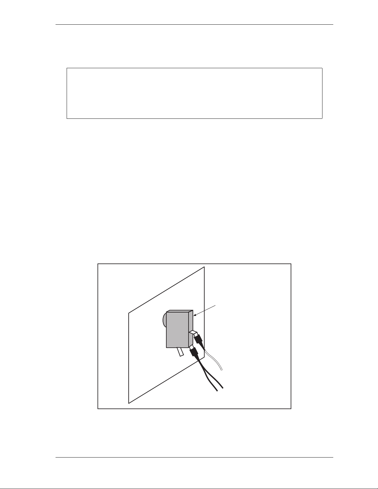
WPC 2000 User Manual 1128500
NOTICE
No connection
Yellow wire
2 Black wires
Switch body
(Reset/Select button)
Enclosure
or console
7. Connect the display cable from TB706 on the Display board to TB108 on the Main
Processor board, referring to Table 2-15, page 2-54 for wiring connections.
CONNECT DISPLAY CABLE CORRECTLY
Make sure that the display cable is connected correctly at both ends. Connect the display
cable to TB706 on the Display board with the black wire closest to the small numeral 1
toward the bottom of the board. The black wire indicates pin #1.
8. Install the Reset/Select button in the left cutout below the display. Wiring for the Reset/
Select button is provided on the Settings key switch wiring harness (see step 10).
9. Install the Mute lamp in the center cutout. The Mute lamp includes wiring that you
connect to terminals on the WPC 2000 Main Processor board.
10. Install the Settings key switch in the right cutout. The Settings key switch includes a
wiring harness with connectors for attachment to the Reset/Select button and the WPC
2000 Display board.
11. Slide the connector at the end of the yellow wire on one arm of the Settings key switch
wiring harness over the topmost terminal on the switch body of the Reset/Select button, as
shown in Figure 2-31.
Slide the connector at the end of the two black wires on the same arm of the wiring
harness over the lower terminal on the Reset/Select button switch body, as shown in
Figure 2-31.
Figure 2-31. Reset/Select Button Wiri ng Connections
Installation 2-57
Page 85

1128500 WPC 2000 User Manual
NOTICE
NOTICE
DANGER
!
NOTICE
12. Plug the connector on the other arm of the Settings key switch wiring harness into J707
on the WPC 2000 Display board.
13. Connect the wiring from the mute lamp to pins #76 (+24 Vdc) and #54 (Ground) on the
WPC 2000 Main Processor board (see Figure 1 at the end of the manual).
SPLICE ADDITIONAL WIRING ONTO MUTE LAMP WIRING
The mute lamp comes with a 3 in. wire pigtail. You will need to butt splice an additional
length of wire to the pigtail to make connections at the Main Processor board. Use 18 or
20 AWG wire and a Wintriss-supplied butt splice (part. no. Amp # 8-34070-4) or
equivalent.
14. Install the selector switches.
15. Wire each selector switch to the appropriate terminal block on the WPC 2000 Display
board, referring to T able 2-16, page 2-55 and Figure 5 at the back of the manual for wiring
connections.
JUMPER JP720 ON DISPLAY BOARD MUST BE SET TO R (RUN) POSITION
DO NOT change the position of jumper JP720 on the WPC 2000 Display board. This
jumper comes from the factory in the R (or Run) position (see Figure 2-16, page 2-34 and
Figure 1 at the end of the manual). If you set JP720 to the M (or Monitor) position, the
clock display will not turn on.
Installation Verification
PERFORM INSTALLATION VERIFICATION BEFORE OPERATING PRESS
Complete Installation Verification procedures before operating the press.
Failure to comply with these instructions will result in death or serious injury.
ALL SIGNAL GROUNDS MUST BE CONNECTED THROUGH THE MAIN PROCESSOR BO ARD
Connect all signal grounds through pins on the WPC 2000 Main Processor board.
When you have completed all the installation procedures in this chapter, perform the
following Installation Verification steps before setting up and initializing WPC 2000 as
instructed in Chapter 3. When you have completed initialization and set-up procedures, be
sure to perform the Final Checkout tests at the end of Chapter 3.
2-58 Installation
Page 86

WPC 2000 User Manual 1128500
DANGER
!
DANGER
!
Checking Safeguarding Devices
DO NOT USE NON-SAFETY INTERLOCK SWITCHES IN SAFETY APPLICATIONS
• Ensure that all interlock switches used on safeguards are designed and rated for safety
applications. Check with the manufacturer to verify the rating of each interlock switch.
• Ensure that safe ty int erl ock switch es a re co nne cted t o co ntro l-r eli abl e inpu t s if t hey are u sed for
safeguarding applications.
Failure to comply with these instructions will result in death or serious injury.
PREVENT INJURY DURING TESTING
• Keep all personnel away from the press during testing.
• Be sure there is no die or other tooling in the press during testing.
• Use extreme caution when testing moveable guards. Keep hands and other body parts outside
the guarded area.
Failure to comply with these instructions will result in death or serious injury.
Before turning on the press, check to verify the following conditions:
• All fixed safeguards prevent entry of a hand or other body part into the hazardous area.
• All moveable safeguards are correctly installed and wired to prevent operation of the press
when they are open and prevent entry of a hand or other body part into the hazardous area.
• All interlock switches used with safeguards are designed and rated for use in safety
applications. Check with the switch manufacturer to confirm their suitability for safety use.
• Interlock switches used for safeguarding are connected to control-reliable inputs.
• Any light curtains are installed and working properly.
• Any Two-hand controls used as safeguarding devices are mounted at least the safety
distance from the hazardous area.
• Safeguards are in place to prevent entry to the hazardous area under, over or around light
curtains or other safeguarding devices.
Test safeguarding devices as follows:
1. Run the press in Inch mode. Block the light curtain, if one is installed, with an opaque
object. The press should stop immediately.
• If the press stops, go to the next step.
• If the press does not stop, check the wiring of the light curtain and correct any problems.
Repeat the test. If the press still doesn’t stop, call Wintriss Tech. Support.
Installation 2-59
Page 87

1128500 WPC 2000 User Manual
WARNING
!
2. Run the press in Inch mode. Keeping hands outside the guarded area, open one of the
moveable guards just enough to open the interlock switch. The press should stop
immediately.
• If the press stops immediately when you open the guard, go to the next step.
• If the press does not stop, check the wiring of the moveable guard and correct any
problems. Repeat the test. If the press still doesn’t stop, call Wintriss Tech. Support.
3. Close the guard you just tested, reset the press control, and repeat step 2 for each
moveable guard. When you have tested all moveable guards, go to the next section.
Checking Dual Safety Valve (DSV) Wiring
PREVENT ELECTRIC SHOCK WHEN WORKING INSIDE THE ENCLOSURE
Turn off and disconnect power from the WPC 2000, the press and any other machinery it is
connected to before working inside the enclosure. This includes power to the press motor.
Failure to comply with these instructions could result in death or serious injury.
Follow the checkout procedure below to ensure that the dual safety valve is wired correctly.
Proper installation and operation of the DSV is crucial to personnel safety.
1. Power down the press and press control.
2. On the DSV/Lockout Relay board (see Figure 2-12, page 2-23 or Figure 2-13, page 2-24
for location), remove fuse F302 or F303. F302 and F303 are the DSV fuses.
3. Power up the press and press control, select INCH with the Stroke Select switch, and push
both Run/Inch buttons. Observe what happens.
• If the ram does not move and the display shows F79 or one of the DSV faults (see
page 5-16), the DSV is operating properly. Go to the next step.
• If the ram moves and/or the display shows a fault other than F79 or one of the DSV
faults, check the wiring of the DSV and correct any problems, then repeat step 3. If the
ram still moves and/or the display still shows a fault other than F79 or one of the DSV
faults, power down the press immediately, and call Wintriss Tech. Support.
4. Power down the press and press control.
5. On the DSV/Lockout Relay board, replace the DSV fuse (i.e., F302 or F303) you removed
in step 2, and remove the other DSV fuse.
6. Power up the press and press control, make sure the press is in Inch mode, and push both
Run/Inch buttons. Observe what happens.
• If the ram does not move and the display shows F79 or one of the DSV faults, the DSV
is operating properly. Go to the next step.
• If the ram moves and/or the display shows a fault other than F79 or one of the DSV
faults, check the wiring of the DSV and correct any problems, then repeat step 6. If the
2-60 Installation
Page 88

WPC 2000 User Manual 1128500
ram still moves and/or the display still shows a fault other than F79 or one of the DSV
faults, power down the press immediately and call Wintriss Tech. Support.
7. Power down the press and press control, and replace the fuse you removed in step 5.
8. Power up the press and press control, make sure the press is still in Inch mode, and push
both Run/Inch buttons briefly. The ram should move.
• If the ram moves, go to the next section.
• If the ram does not move, check the wiring of the DSV and correct any problems.
Power up the press and press control. Push the Run/Inch buttons again. If the ram still
does not move, call Wintriss Tech. Support.
Checking for Faults
To check for faults, do the following:
1. Run the press in Inch for a few strokes.
• If the press runs normally, go to the next section.
• If a fault appears on the display, look up the fault code in Chapter 5, and follow the
remedy provided. Once the problem is corrected, press the Reset/Select button, and run
the press again in Inch for a few strokes, checking for error codes. If you need
assistance, call Wintriss Tech. Support.
Checking the Emergency-stop Circuit
To check the Emergency-stop circuit, do the following:
1. Run the press in Inch mode. While the ram is moving, have someone push the Emergency
Stop button on the Operator Station. The press should Emergency-stop immediately.
• If the press Emergency-stops, go to the next section.
• If the press does not Emergency-stop, there is a problem in your E-stop circuit.
Recheck wiring and correct any problems, then repeat this test. If the press still does not
Emergency-stop, call Wintriss Tech. Support. Do not continue with this checkout
procedure until the press E-stops correctly.
Installation Verification Complete
The WPC 2000 Installation Verification procedure is complete. Clear any error message by
pressing the Reset/Select button.
Wiring Tables
Tables showing WPC 2000 wiring connections are provided on the following pages.
Installation 2-61
Page 89

1128500 WPC 2000 User Manual
Table 2-17. WPC 2000 Main Processor Board, TB101-TB104: Wiring Connections
Pin Signal Pin Signal
TB104 Top TB104 Bottom
44 Analog ground 88 Light curtain B2 input **
43 Counterbalance air (Analog 2) input 87 Light curtain A2 input **
42 +24 Vdc output 86 User input 10 – (paired w/ User Input 1 1*)
41 +24 Vdc output 85 User input 8 – (paired w/ User Input 9*)
40 +24 Vdc output 84 User input 6 –
39 +24 Vdc output 83 User input 4 –
38 +24 Vdc output 82 User input 2 +
37 +24 Vdc output 81
36 Aux. 2 output 80 Top-stop string center loop connection
35 Light curtain 2 enable 79 Top-stop string drive output
Top-stop string input (connects internally to 49)
TB103 Top TB103 Bottom
34 Analog ground 78 Light curtain B1 input **
33 Main system air (Analog 1) input 77 Light curtain A1 input **
32 +24 Vdc output 76 Mute lamp 2 output +
31 Ground 75 Unused input –
30 Ground 74 User input 9 – (paired w/ User Input 8*)
29 Aux. 3 output 73 User input 7 –
28 Aux. 1 output 72 User input 5 –
27 Light curtain 1 enable 71 User input 3 +
26 Unused input + 70 Remote reset input –
25 Ground 69
24 Overrun limit switch input - 68 E-stop string center loop connection
23 +24 Vdc output 67 E-stop string drive output
E-stop string input (connects internally to 45)
TB102 Top TB102 Bottom
22 Top stop limit switch input – 66 Mute lamp 1 output +
21 User input 1 + 65 Palm time lamp output –
20 DSV monitor input + 64 Prior act lamp output –
19 Unused input – 63 Prior act B input +
18 User input 11 – (paired w/ User Input 10*) 62 Prior act B output
17 Motor reverse input + 61 Prior act A input (connects internally to 62)
16 Bar actuator input + 60 Top-stop B2 input + pulse
15
Auto. Single-stroke (Ext. Trip) actuator N/C +
14 Foot switch N/O input + 58
13
Top Stop in Inch Disable input +
12 Palm switch B N/O input + 56 E-stop B2 output
11 Palm switch A N/O input + 55 E-stop A2 input (connects internally to 56)
59 Top-stop B2 output
Top-stop A2 input (connects internally to 59)
57 E-stop B2 input + pulse
TB101 Top TB101 Bottom
10 Ground 54 Ground
9 +24 Vdc output 53 +24 Vdc output
8 Clutch air pressure switch input – 52 Top-stop B1 input + pulse
7 Motor forward input + 51 Top-stop B1 output
6 Bar selector switch input + 50
5
Auto. Single-stroke (Ext. Trip) actuator N/O +
4 Foot switch N/C input + 48 E-stop B1 input + pulse
3 One hand A input + 47 E-stop B1 output
2 Palm switch B N/C input + 46 E-stop A1 input (connects internally to 47)
1 Palm switch A N/C input + 45 E-stop A output
*See Wiring WPC 2000 User Inputs, page 2-28.
** Input polarity depends on setting (NPN or PNP) of Light Curtain Output Type jumpers (JP121 and JP123) on
WPC 2000 Main Processor board (see Fig ure 2-12, page 2-23 or Figure 2-13, page 2-24).
Top-stop A1 input (connects internally to 51)
49 Top-stop A output
2-62 Installation
Page 90

WPC 2000 User Manual 1128500
Table 2-18. Power Supply (TB105) Wiring
Pin #
90 +24 Vdc input
89 COM
Signal
Table 2-19. Aux. E-stop Relay Board Wiring
Pin #
96 Circuit 3 output
95 Circuit 3 input
94 Circuit 2 output
93 Circuit 2 input
92 Circuit 1 output
91 Circuit 1 input
Signal
Table 2-20. DSV/Lockout Relay Board Wiring
Pin #
103 DSV B relay output
102 DSV B relay input
101 DSV A relay output
100 DSV A relay input
99 Lockout relay output
98 Lockout relay output
97 Lockout relay input
Signal
Table 2-21. Resolver (TB 106) Wiring
CW (clockwise) rotation shown, viewing shaft end.
For CCW, reverse black and yellow wires.
Pin #
104 S4 Return Brown
105 R2 Ground Orange
106 S3 Return Yellow
107 R1 Drive Red
108 S2 Cosine Green
109 S1 Sine Black
110 Shield
Signal Wire Color
Table 2-22. Cam Outputs (TB 109) Wiring
Pin #
130 Cam 1
129 Cam 2
128 Cam 3
127 Cam 4
126 Counter
125 Zero cam
124 Spec 1
123 Spec 2
122 Ground
121 +24 Vdc
Signal
Table 2-23. Display Board Wiring
Pin #
157 Micro-inch selector input –
156 Cams selector input –
155 Ground
154 Operator station 1 selector input –
153 Operator station 2 selector input –
152 Ground
151
150 Ground
149 One hand selector input –
148 Foot selector input –
147 Spare selector input –
146 Ground
145 Off selector input –
144 Inch selector input –
143 Single-stroke selector input –
142 Continuous selector input –
141 Ground
Signal
External/Two break selector input –
Table 2-24. AC Power Wiring
Pin #
Signal
L1 (Hi)
L2 (Neutral)
Ground
Installation 2-63
Page 91

1128500 WPC 2000 User Manual
2-64 Installation
Page 92

Chapter 3. Initialization, Setup, and
DANGER
!
DANGER
!
DANGER
!
Checkout
OPERATOR STATION WIRED INCORRECTLY
Run all necessary tests to verify that each Operator Station is wired correctly and provides proper
anti-tie-down and anti-repeat protection.
Failure to comply with these instructions will result in death or serious injury.
MORE OPERATORS THAN OPERATOR STATIONS
• Ensure that there are the same number of active operator stations as there are operators if the
press is not equipped with properly installed and operating light curtains.
• During setup, lockout/tagout the press if there are more operators than operator stations.
• Verify at every shift change that there are the same number of active operator stations as there
are operators if the press is not equipped with properly installed and operating light curtains.
Failure to comply with these instructions will result in death or serious injury.
TWO-HAND CONTROL TOO CLOSE TO HAZARDOUS AREA
Verify at each shift change that any moveable Two-hand controls are located at least the safety
distance from the pinch point or hazardous area.
Failure to comply with these instructions will result in death or serious injury.
This chapter shows you how to initialize and set up your WPC 2000 and perform final
checkout tests.
Viewing and Setting Press Parameters
The WPC 2000 allows you to view and, in some cases, to set the following press parameters:
• Crankshaft angle or strokes per minute (SPM)
• 90° stop time test result
• Counter
• Stopping time
• Counter preset
• Stopping angle
• Top-stop angle
• Stop-time limit
• Auto carry-up angle
• Micro-inch time setting
Initialization, Setup, and Checkout 3-1
Page 93
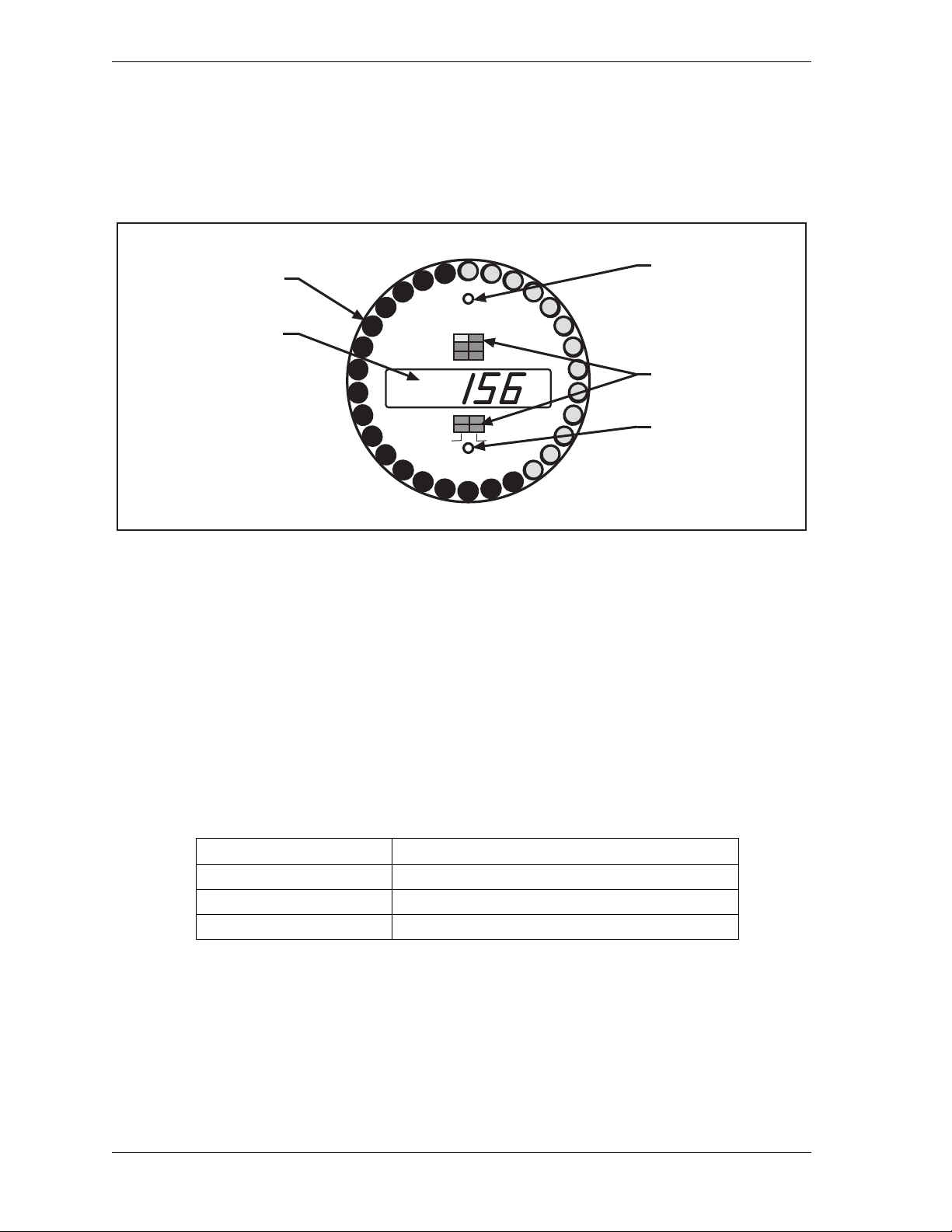
1128500 WPC 2000 User Manual
Digital Display
Crank Angle
Press Speed
Counter
Error Codes
Settings
Crank-angle Clock
LEDs
Display Indicator
Segments
Interrupted Stroke
LED
Brake Warning
LED
BRAKE WARNING
INTERRUPTED STROKE
TOP STOP ANGLE
AUTO CARRYUP
STOP TIME LIMIT
MICRO-INCH
STOPPING TIME
STOPPING ANGLE
90
° STOP TEST
COUNTER
COUNTER PRESET
ANGLE / SPM
cam on angle
cam off angle
To select a parameter so you can view or adjust its setting, press the Reset/Select button on the
WPC 2000 display until the indicator segment for that parameter is illuminated. The value of
the parameter appears in the digital LED readout. Locations of the indicator segments on the
WPC 2000 display are shown in Figure 3-1.
Each time you press the Reset/Select button, the next indicator segment in the sequence is
illuminated. To illuminate the group of four indicator segments in the lower half of the
display, you must switch the press to Inch mode.
“Angle/SPM” is the default indicator segment when the press is in Inch mode, the crankshaft
angle being displayed in the digital LED readout. Whenever you change operating mode to
Single-stroke or Continuous, “Counter” becomes the active (i.e., illuminated) segment, and
the current parts count is displayed in the digital readout. These defaults are summarized in
Table 3-1. When the press is stopped and “Angle/SPM” is selected, the crankshaft angle is
displayed for all Stroke Select settings.
When the default indicator segment is selected, the crank-angle clock shows the crankshaft
angle of the press in all Stroke Select settings. Each LED on the clock represents
approximately 11°. The crank-angle clock shows the press Stopping Angle, Top-stop Angle,
and Auto Carry-up Angle when those indicator segments are illuminated.
3-2 Initialization, Setup, and Checkout
Figure 3-1. WPC 2000 Display Showing Indicator Segments
Table 3-1. WPC 2000 Display: Default Parameters (Press Running)
Stroke Select Setting Parameter Shown in Digital LED Display
Inch * Crankshaft angle (in degrees)
Single-stroke Parts count
Continuous Parts count
* The Counter does not operate in Inch mode.
Page 94
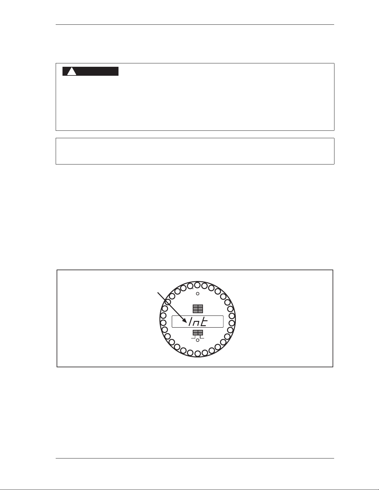
WPC 2000 User Manual 1128500
DANGER
!
NOTICE
BRAKE WARNING
INTERRUPTED STROKE
TOP STOP ANGLE
AUTO CARRYUP
STOP TIME LIMIT
MICRO-INCH
STOPPING TIME
STOPPING ANGLE
90
° STOP TEST
COUNTER
COUNTER PRESET
ANGLE / SPM
Sytem Initialized message
cam on angle cam off angle
Initializing the System
INCORRECT STOP-TIME LIMIT AFTER INITIALIZATION
Determine the Stopping Time and set the Stop-time Limit to a value that reflects the actual
Stopping Time of your press whenever you initialize WPC 2000. Use the stop time measured in
the 90° stop time test to calculate the safety distance. When you initialize WPC 2000, the
Stop-time Limit is returned to its factory setting of 500 mS.
Failure to comply with these instructions will result in death or serious injury.
To initialize only the Start-time Limit, see page 3-5.
After you have completed installation of WPC 2000 and run the Installation Verification tests,
you should first initialize the WPC 2000 system. To do so, perform the following steps:
1. Verify that your press is at top dead center (TDC), using a dial indicator or other means.
TDC is considered to be any position between 358° and 2°. Inch the press to TDC if
necessary.
2. Turn off power to the WPC 2000.
3. Turn the WPC Settings key switch to its “+” setting (i.e., counterclockwise) and turn
power to the WPC 2000 back on. When the message “Int” appears in the LED display
(see Figure 3-2), release the key.
Figure 3-2. WPC 2000 Display Showing “System Initialized” (“Int”) Message
Initialization, Setup, and Checkout 3-3
Page 95

1128500 WPC 2000 User Manual
BRAKE WARNING
INTERRUPTED STROKE
TOP STOP ANGLE
AUTO CARRYUP
STOP TIME LIMIT
MICRO-INCH
STOPPING TIME
STOPPING ANGLE
90
° STOP TEST
COUNTER
COUNTER PRESET
ANGLE / SPM
Resolver Zeroed message
cam on angle cam off angle
This procedure returns the following WPC 2000 parameters to their factory settings:
• Stop-time Limit–Set to 500 milliseconds. When you begin operating your press, you must
adjust this setting (see Setting the Stop-time Limit, page 3-16).
• Start-time Limit–Set to two times the S tart T ime measured by WP C 2000 on the first stroke
after the system has been initialized. The Start Time is the interval between the closing
(turning on) of the output relays on the DSV/Lockout Relay board, which provides the
signal for the Dual Safety Valve (DSV) to energize, and the resolver signal, which indicates
that the crankshaft has begun to turn. The greater part of this interval is the time it takes for
the clutch mechanism to activate and engage.
The Start-time Limit allows WPC 2000 to detect resolver drive failure. When the
measured Start Time exceeds the Start-time Limit, WPC 2000 sends a Stop signal to the
press and displays fault code F79 (see Loss of Rotation, page 5-17).
There are times when you may need to initialize only the Start-time Limit, such as during
troubleshooting (see page 3-5 for instructions).
• Resolver Zero Setting–Set to zero.
Re-zeroing the Resolver
If you need to zero the resolver without re-initializing the Start-time and Stop-time limits,
follow these steps:
1. Verify that your press is at top dead center (TDC), using a dial indicator or other means.
TDC is considered to be any position between 358° and 2°. Inch the press to TDC if
necessary.
2. Turn off power to the WPC 2000.
3. Press and hold the Reset/Select button and turn power to the WPC 2000 back on. When
the message “rES” appears in the LED display (see Figure 3-3), release the key.
3-4 Initialization, Setup, and Checkout
Figure 3-3. WPC 2000 Display Showing “Resolver Zeroed” (“rES”) Message
When you use this procedure to zero the resolver, WPC 2000 electronically adds or
subtracts any offset between the resolver and the crankshaft, so the resolver always knows
Page 96

WPC 2000 User Manual 1128500
NOTICE
BRAKE WARNING
INTERRUPTED STROKE
TOP STOP ANGLE
AUTO CARRYUP
STOP TIME LIMIT
MICRO-INCH
STOPPING TIME
STOPPING ANGLE
90
° STOP TEST
COUNTER
COUNTER PRESET
ANGLE / SPM
Initializaing Start-time Limit
message
cam on angle cam off angle
the true zero position of the ram. After zeroing, if the press is at TDC, the crank angle
value in the LED display should read 0°. If it does not, repeat the zeroing process.
Initializing Only the Start-time Limit
The Start-time Limit value cannot be changed manually.
If you want to re-initialize only the Start-time Limit without re-initializing the Stop-time
Limit and Resolver Zero settings (see Initializing the System, page 3-3), do the following:
1. Power down WPC 2000.
2. While powering WPC 2000 back up, turn the WPC Settings key switch to “–” (i.e.,
clockwise) and hold it there. When “Str” appears in the LED display (see Figure 3-4),
release the key.
Figure 3-4. WPC 2000 Display Showing “Initializing Start-time Limit” (“Str”) Message
The next time you start the press, WPC 2000 will set the St art-time Limit t o twice the Start
Time measured on the first stroke. This value cannot be changed manually.
Viewing the Start-time Limit
To view the Start-time Limit, do the following:
1. Press the Reset/Select button repeatedly, until the “Stopping Angle” indicator segment
illuminates.
2. Turn the WPC Settings key switch to “–” (i.e., clockwise). The Start-time Limit in
milliseconds is shown in the LED display.
Viewing the Last Start Time
To view the Start Time measured the last time you started your press, do the following:
Initialization, Setup, and Checkout 3-5
Page 97

1128500 WPC 2000 User Manual
WARNING
!
NOTICE
NOTICE
1. Press the Reset/Select button repeatedly until the “Stopping Angle” indicator segment
illuminates.
2. Turn the WPC Settings key switch to “+” (i.e., counterclockwise). The Start Time in
milliseconds that was measured the last time you started the press is shown in the LED
display.
Installing the Overrun Sensor Magnet
INCORRECT INSTALLATION OF OVERRUN LIMIT SWITCH
Ensure that the overrun sensor magnet is installed at a proper location if you have Two-hand
Control without light curtains, or light curtains with muting. Proper installation of the magnet
ensures that if the Top-stop output relay fails, a hazardous situation will not occur on the
downstroke. The magnet must be mounted as close as possible to the Top-stop “On” Angle (see
Table 3-2, page 3-8).
Failure to comply with these instructions could result in death or serious injury.
This section shows you how to install the magnet that, with the overrun sensor, makes up the
overrun limit switch. You should already have installed the overrun sensor (see page 2-25).
The overrun limit switch enables WPC 2000 to monitor operation of the resolver and to stop
the press whenever the resolver fails to work properly.
The press cannot be run in Continuous or Single-stroke unless the overrun sensor and magnet
are installed and working correctly. Without the overrun limit switch, you can only operate
the press in Inch.
The angle at which you mount the magnet depends on the Top-stop “On” Angle. You must
first determine and set the Top-stop “On” Angle before installing the magnet.
Setting the Top-stop “On” Angle
For a variable-speed press, you need to determine the latest Top-stop “On” Angle, which is the
angle at which the press top-stops at its slowest speed and with the shortest stopping angle/time.
BEFORE YOU SET THE TOP-STOP “ON” ANGLE, MAKE SURE THAT
• The press ram has been mechanically set to top dead center (TDC) (see NOTICE on page 2-2)
• The resolver has been aligned as close as possible to TDC (i.e., 0° ±2°) (see Mounting the
Resolver, page 2-21)
• The resolver has been zeroed (see page 3-4)
To determine the angle at which the Top-stop command is given on your press and change the
Top-stop “On” Angle setting on the WPC 2000 display, do the following:
3-6 Initialization, Setup, and Checkout
Page 98

WPC 2000 User Manual 1128500
NOTICE
NOTICE
1. Make sure the following WPC 2000 features are set correctly:
• Option switches 1 and 2 on switch block S101 on the WPC 2000 Main Processor board
should be set to OFF so that any Top-stop “On” Angle between 211° and 355° can be set
on the WPC 2000 display. See Figure 2-12, page 2-23 or Figure 2-13, page 2-24 for
location of the switch block and Switches 1 and 2 – Top-stop “On” Angle Range,
page 3-26 for instructions on how to set the switches.
• Pin #13 on the WPC 2000 Main Processor board should not be wired in order to disable
Top-stop in Inch (see Top-stop Bypass (Top-stop in Inch Disabled), page 4-9).
• Micro-inch (if you have wired this feature) should be disabled (see Wiring Micro-inch,
page 2-33).
• Option switch 4 on switch block S101 should be set to OFF to disable the Auto
Compensated Top Stop (ACTS) feature (see page 3-28). ACTS compensates for
increases in press speed by adjusting the Top-stop “On” Angle backward (i.e.,
decreasing the “on” angle).
2. Power down, then power up the WPC 2000 to enable the new settings.
3. Clear the “Loc” message on the WPC 2000 display by turning the Stroke Select switch to
OFF, then to INCH.
If you have a variable-speed press, set the press to the slowest production speed, but not
slower than 6 SPM.
4. With the press in Inch mode, press the Reset/Select button until the “Top Stop Angle”
indicator is lit.
The Top-stop “On” Angle is set at the factory to 211°. If you haven’t changed the default
setting, you can skip step 5.
5. Temporarily set the Top-stop “On” Angle to 211°, using the WPC Settings key switch.
Turning the key to “+” (counterclockwise) increases the angle; turning the key to “–”
(clockwise) decreases the angle.
6. Press the Reset/Select button repeatedly until the “Angle/SPM” indicator is lit. This
action saves your Top-stop “On” Angle setting.
7. With the press still in Inch mode and the main motor on, press and hold both Run/Inch
palm buttons until the press top-stops.
8. Note the crankshaft angle shown in the LED display. Subtract the displayed value from
360°, then add the result to the default 211° Top-stop “On” Angle setting. This is your
calculated Top-stop “On” Angle.
Initialization, Setup, and Checkout 3-7
Page 99

1128500 WPC 2000 User Manual
NOTICE
EXAMPLE
If the displayed Top-stop “On” Angle is 287°, you would calculate as follows:
360° - 287° = 73°
211° + 73° = 284°
You would set your Top-stop “On” Angle to 284°.
WHEN DETERMINING TOP-STOP “ON” ANGLE
Remember that the Top-stop angle has an internal dwell of 20°. The internal Top-stop
timing turns off 20° after the Top-stop angle that you set. This internal Top-stop timing
must turn off before the overrun limit switch turns on. If the Top-stop timing and the
overrun limit switch are “on” simultaneously, an “80 series” error code will display (see
Top-stop and Overrun Setting Faults, page 5-18).
9. Select the “Top Stop Angle” indicator, and set the Top-stop “On” Angle to the value you
calculated in step 8.
10. Save the new Top-stop “On” Angle setting by pressing the Reset/Select button until the
“Angle/SPM” indicator is lit.
11. Determine the angle at which to install the overrun sensor magnet, referring to Table 3-2.
First, locate the cell in the “Top-stop Angle” row displaying the range of angles within
which your calculated Top-stop “On” Angle falls; then, move down one row in that
column to find the mounting angle for the overrun sensor magnet. If you wish, you can
use the “Your Settings” column in the second row to record the correct mounting angle.
Table 3-2. Overrun Sensor Magnet Location and Option Switch Settings
Top-stop Angle
Magnet Mounting Angle
Switch 1 Setting
Switch 2 Setting
Example
You calculated in step 8 that your Top-stop “On” Angle is 284°, which falls in the 271° to
300° column in Table 3-2. The correct mounting angle for the overrun sensor magnet would
be 330°. See Figure 3-5.
< 240° 241° to 270° 271° to 300° > 301° Your Settings
270° 300° 330° 359°
ON ON OFF OFF
ON OFF ON OFF
3-8 Initialization, Setup, and Checkout
Page 100

WPC 2000 User Manual 1128500
Figure 3-5. Setting Overrun Timing: Example
12. Determine the option switch 1 and 2 settings required for your calculated Top-stop “On”
Angle, referring to Table 3-2. WPC 2000 uses these settings to determine at what angle to
begin the overrun sensor closure test, which is used to make sure that the overrun limit
switch closes at the same angle on every stroke.
Move down from the cell in which the correct magnet mounting angle falls (see step 1 1) to
find the correct switch settings in last two rows of the table. If you wish, you can use the
“Your Settings” column in those rows to record those settings.
Example
You calculated in step 8 that your Top-stop “On” Angle is 284°, which falls in the 271° to
300° column in Table 3-2. The correct switch settings would be OFF for switch 1 and ON
for switch 2. See Figure 3-5.
13. Set option switches 1 and 2 on S101 on the WPC 2000 Main Processor board to the
positions you determined in step 12, referring to page 3-26 for instructions.
14. If you are using the Auto Compensated Top Stop feature, return switch 4 on S101 to its
ON setting to enable it (see step 1).
15. Power down, then power back up the WPC 2000 to enable the new option switch settings.
Mounting the Overrun Sensor Magnet
To mount the overrun sensor magnet, perform the following steps:
Initialization, Setup, and Checkout 3-9
 Loading...