

Page 1

®
®
Shadow VI
Safety Light Curtain
1107200
Rev. E July 2010
®
Tech Support Hotline 800-586-8324 8-5 EST
Wintriss Controls Group, LLC
100 Discovery Way
Unit 110
Acton MA 01720 USA
Phone (800) 586-8324
Fax (978) 263-2048
PRINTED IN USA DA46072
www.wintriss.com
Page 2

Requirements You Must Meet When Installing and Using
Shadow Safety Light Curtains
!
DANGER
FULL REVOLUTION MECHANICAL POWER PRESSES AND OTHER MACHINES CANNOT BE STOPPED IN MID-
STROKE OR MID-CYCLE
• DO NOT use Shadow safety light curtains on full-revolution clutched machinery or other equipment that cannot be stopped
at any point in its stroke or cycle.
• Use Shadow safety light curtains only on machinery that can be stopped at any point in its stroke or cycle.
Failure to comply with these instructions will result in death or serious injury.
!
DANGER
IMPROPER INSTALLATION, USE OR MAINTENANCE
• Follow all procedures in this manual. Perform only the tests and repairs listed in this manual. Use only factory-supplied
replacement parts.
• Wire, install and maintain Shadow safety light curtain in accordance with OSHA lockout/tagout regulation 1910.147.
• Ensure that Shadow safety light curtain is installed, tested and repaired by qualified personnel.
• Ensure that all metal stamping presses on which Shadows are used meet the requirements and inspection procedures of
OSHA regulation 1910.217 and ANSI standard B11.1-2009, which govern the use of presence-sensing devices on metal
stamping presses. Ensure that all other machinery, or other devices on which Shadows are used, meet the general
machine guarding requirements in OSHA standard 1910.212 and any other regulations and standards that apply.
• Ensure that guarding is installed to prevent access to the machine over, under or around the light curtains.
• Test the operation of your Shadow safety light curtain daily using the checkout sequence shown on the Shadow safety
light curtain units and also listed in this manual. If your Shadow safety light curtain is installed so the warning and test
procedure labels are not clearly visible, call the factory for extra warning labels to affix to your machinery in a visible area.
• Perform the checkout sequence after any maintenance is done on the Shadow safety light curtain.
• Ensure that supervisors, die-setters, maintenance persons, machine operators, foremen, or any others responsible for the
proper operation of the machinery have read and understood all instructions for use of the Shadow light curtain.
Failure to comply with these instructions will result in death or serious injury.
!
DANGER
MACHINERY NOT CONFIGURED OR WORKING PROPERLY
• Ensure that the machinery and devices on which Shadow safety light curtains are used meet the general machine
guarding requirements of OSHA standard 1910.212 and any other regulations and standards that apply.
• Inspect all stopping mechanisms of the machinery regularly to be sure they work properly.
• DO NOT operate a machine equipped with Shadow safety light curtains if the machine or any of its stopping mechanisms
is not in proper working order.
Failure to comply with these instructions will result in death or serious injury.
!
DANGER
STOPPING MECHANISM FAILURE
• Install and maintain stopping mechanisms of machinery or other devices according to the applicable regulations or
standards.
• Regularly inspect all stopping mechanisms of the machinery to ensure proper functioning.
Failure to comply with these instructions will result in death or serious injury.
!
DANGER
OTHER EQUIPMENT CONTINUING TO OPERATE
• Equipment that operates with the machinery connected to Shadow safety light curtain may continue to operate after the
machinery has received a stop signal.
• Ensure that all operators and other affected personnel know which equipment is connected to Shadow safety light curtain
and which is not.
Failure to comply with these instructions will result in death or serious injury.
!
WARNING
ELECTRIC SHOCK HAZARD
Turn off and disconnect power from Shadow safety light curtain and from the machinery it is connected to before making
any wiring connections. This includes power to the machine control and motor.
Failure to comply with these instructions could result in death o r serious injury.
Page 3

Changes for Revision E of the
Shadow VI User Manual
(1107200)
This revision of the Shadow VI Safety Light Curtain User Manual covers Shadow VI models
with response times of 30 to 40 ms, maximum.
The changes include:
• The Remote Interrupt button has been removed from the Shadow VI Control board (see
page 44) , and, as a result, all references to the button have been removed from the
manual.
• AC power is now grounded to the set screw terminal on the Shadow VI enclosure rather
than to pin #3 on TB 1 (see page 51).
• The procedure for replacing Shadow VI safety relays has been updated. Instead of
replacing individual relays in the event of a relay failure, you now must replace the
Shadow VI Control board. See page 91.
• References to and excerpts from ANSI standards B11.1 and B11.19 have been updated to
their current versions, B11.1-2009 and B11.19-2003. See Appendix A.
Page 4

Thank you for purchasing a Wintriss Product. We appreciate your business and want to do whatever
we can to ensure your satisfaction. Wintriss products are built to stay on the job day after day, and are
backed by an ironclad guarantee, international standards approvals, and unbeatable support. Whenever
you need assistance or service, we back all our products with excellent spare parts inventories, training
programs, and prompt repair service. We would like to share with you a list of service options–probably
the largest number of service options offered in the industry.
• Technical Assistance
We offer a toll-free line for technical assistance. Call our Wintriss Technical Support Hotline at
1-800-586-TECH (8324) should you have any questions about your equipment. Our technical
staff is ready to assist you Monday through Friday, 8 a.m. to 5 p.m. EST. In many cases our
experienced technical staff can resolve your inquiry right over the phone.
• Return Authorization
Please call our “800” number for a return authorization (RMA) number to return a product for
repair. Returned goods must arrive freight prepaid. In order to process your return quickly, we
ask that you provide us with the following pertinent information when you call: purchase order
number, shipping address, contact name and telephone number, and product type. The assigned
RMA number should appear on all packages returned to Wintriss Controls Group to ensure prompt
service.
At the time of requesting an RMA, you will be quoted a flat-rate repair price for the product you
are returning. We ask that you either fax us a PO for that amount or enclose the PO with the
returned item. This will enable us to ship the item back to you as soon as the repair has been
completed. If the item cannot be repaired or there are additional charges, you will be contacted for
approval.
Please be sure to carefully pack all returned items and ship to our Acton, MA location.
• Expedited Repair Program
Rush service providing 48 hour turnaround is available for most products upon request. An
Expedite Fee will be applied to our standard repair rate.
• Board Exchange Program
If your needs are urgent, you can take advantage of out Board Exchange (EX) program. Call our
“800” number between 8 a.m. to 5 p.m. EST and we will send a replacement to you overnight. A
fee does apply to this service. Contact Wintriss Technical Support at 800-586-8324 for details.
• Service Center
Our Service Center for product service is located at our headquarters in Acton, MA. If your
equipment requires repair, please contact us at 800-586-8324 to obtain a return authorization
number.
Nationwide field service is also available. Contact the Wintriss Technical Support group at
800-586-8324.
• Product Training
We also offer both product training and maintenance/troubleshooting courses at our Acton, MA
and Chicago-area facilities. On-site training is available from the factory or through your local
Wintriss representative.
• Restocking Charge
Returned goods are subject to a 20% restocking charge if returned for credit. The minimum charge
is $50, not to exceed $250 per item.
Whatever the product, we are committed to satisfying you with innovative engineering, quality
construction, reliable performance, and ongoing, helpful support. Call us whenever you need assistance.
Page 5

Table of Contents
Chapter 1 – Introduction to Shadow® VI Safety Light Curtain ........................1
OSHA and ANSI Compliance....................................................................................................................2
About Shadow VI.......................................................................................................................................2
How Shadow Works...................................................................................................................................4
Shadow and Control Reliability .................................................................................................................6
Description of Shadow VI indicators .........................................................................................................7
At the Optic Heads.................................................................................................................................7
At the Control ........................................................................................................................................8
Inside the Control...................................................................................................................................8
Object Sensitivity .......................................................................................................................................8
Size and Scanning Distance........................................................................................................................8
Shadows Are Easy to Maintain ..................................................................................................................9
Shadow VI Features and Options.............................................................................................................10
Weld Shield Kit........................................................................................................................................11
Chapter 2 – Installation and Checkout............................................................15
Installation overview................................................................................................................................16
Calculating the safety distance........................................................................................................16
Mounting location for your Shadow transmitter and receiver ........................................................16
Wiring, aligning, mounting, and making proper settings................................................................16
Ensuring that the Shadow light curtains are working properly.......................................................16
Installation Procedure...............................................................................................................................17
Calculating the Safety Distance................................................................................................................18
OSHA and ANSI Requirements ..........................................................................................................19
The OSHA Safety Distance Formula..............................................................................................20
The ANSI Safety Distance Formula................................................................................................21
Perimeter Guarding.........................................................................................................................24
Blanking Windows Affect Safety Distance ....................................................................................24
Pass-through Protection ..................................................................................................................25
Height Considerations.......................................................................................................................... 26
Designing and Mounting Brackets...........................................................................................................26
Universal Mounts............................................................................................................................26
Mounting Location Requirements...................................................................................................27
How to Design and Mount Brackets or Floor Stands .....................................................................28
Alignment Considerations...............................................................................................................33
Maximum Openings for Side Guards .............................................................................................35
Using Mirrors with Shadows ..........................................................................................................36
Using Weld Shields.........................................................................................................................39
Mounting Shadow Light Curtains Upside Down............................................................................39
Avoiding Cross Talk When Mounting 2 Sets of Shadows .............................................................39
Loosely Mounting Shadow VI Transmitter and Receiver........................................................................40
Mounting the Control...............................................................................................................................42
Shadow VI User Manual 1107200
Table of Contents page i
Page 6

1107200 Shadow VI User Manual
Connecting RF (Radio Frequency) Ground ....................................................................................42
Wiring the Transmitter and Receiver to the Control ................................................................................45
Terminating Shields of the Head Cables..............................................................................................46
Connecting the Head Cables to the Control.........................................................................................47
If You Have a Second Set of Shadow Optic Heads.............................................................................49
Connecting AC Wiring to the Control......................................................................................................50
Connecting Stop Circuits to the Control...................................................................................................52
8A. Wiring Shadow to the WPC (One or Two Control Boxes)......................................................55
8B. Wiring Shadow to a PLC..........................................................................................................56
Optional Wiring........................................................................................................................................57
Indicator Outputs..................................................................................................................................57
MPCE Monitor Inputs..........................................................................................................................58
Making Settings Inside the Control..........................................................................................................59
S1 settings............................................................................................................................................60
S4 Settings ...........................................................................................................................................60
J12 Setting............................................................................................................................................61
Plug in Connector and Replace Cover.................................................................................................61
Aligning and Tightening Down Shadow VI Components........................................................................61
Alignment Procedure ...........................................................................................................................62
Diagnostic Steps to Perform Before Using Shadow.............................................................................63
No Power to Unit ............................................................................................................................63
The Light Curtain Is in a "Reset Required" Condition....................................................................63
If the Transmitter Has No Power or Is Not Functioning.................................................................63
Check Power and Indicator Lights..................................................................................................63
Check Lens Window.......................................................................................................................64
Bring Shadow Heads Close Together .............................................................................................64
Green Light On ...............................................................................................................................64
No Green Light ...............................................................................................................................65
If You Have Two Sets of Shadow Heads........................................................................................65
Green Light On But Still Cannot Start Press...................................................................................65
Final Checkout Sequence .........................................................................................................................66
Chapter 3 – Fixed and Floating Blanking........................................................69
Blanking Windows Affect Safety Distance..............................................................................................70
Adding to Safety Distance for Fixed Blanking....................................................................................71
Adding to Safety Distance for Floating Window.................................................................................71
Installing Blanking Windows...................................................................................................................72
Installing the Master.............................................................................................................................72
Installing Slave Windows ....................................................................................................................75
Floating Window......................................................................................................................................77
Adding to Safety Distance for Floating Window.................................................................................78
How to Enable the Floating Window...................................................................................................78
Chapter 4 – Troubleshooting Shadow VI ........................................................79
How to use this chapter ............................................................................................................................79
Description of Shadow VI Indicators.......................................................................................................80
page ii Table of Contents
Page 7

Shadow VI User Manual 1107200
At the Optic Heads...............................................................................................................................80
At the Control ......................................................................................................................................80
Inside the Control.................................................................................................................................81
External MPCE Monitoring: Checking DS5 and DS6.........................................................................85
Shadow VI Optic Head Connector...........................................................................................................86
Checking and Cleaning Lens Window(s).................................................................................................87
Checking Alignment................................................................................................................................. 87
Alignment Problem or Bad Phototransistor.........................................................................................87
Checking and Replacing Fuses.................................................................................................................88
Checking and Replacing Control Relays..................................................................................................89
If the Relay Has Failed Completely.....................................................................................................89
Checking Relays with a Voltmeter ......................................................................................................90
Replacing Safety Relays ......................................................................................................................91
Checking and Correcting Cross Talk........................................................................................................92
Appendix A – Extracts from OSHA Regulations and ANSI Standards.........93
Extracts from OSHA Regulation 1910.217..............................................................................................93
Extracts from ANSI Standards for Presence-sensing Devices.................................................................97
Daily Tests in English ............................................................................................................................113
Tests Quotidiens du Rideau de Lumiere.................................................................................................114
Daily Tests in French..............................................................................................................................114
Appendix B – Shadow VI Panel Mount..........................................................115
Standard Enclosure Versus Optional Panel Mount ................................................................................115
Preparation for Mounting Shadow Using Your Enclosure.....................................................................115
About Shadow VI Panel Mount Labels .............................................................................................116
Appendix C – Installation of Shadow VI-WPC Control Board.....................119
Mounting Dimensions and Required Clearance.....................................................................................119
About Shadow VI-WPC Control Board Labels.................................................................................120
Wiring Shadow VI optic heads to the board ..........................................................................................124
Connecting AC wiring to WPC..............................................................................................................125
Connecting Stop Circuits to WPC..........................................................................................................126
Making settings on the control board.....................................................................................................127
Floating window setting..................................................................................................................... 127
J12 Setting..........................................................................................................................................128
Reset button............................................................................................................................................129
Appendix D – Replacement Parts..................................................................131
Index ................................................................................................................133
Wintriss Manuals ............................................................................................137
Table of Contents page iii
Page 8

1107200 Shadow VI User Manual
List of Figures
Figure 1-1. Illustration of Shadow Transmitter and Receiver...............................................................................3
Figure 1-2. Illustration of Shadow Control ...........................................................................................................4
Figure 1-3. Showing Light Beams with Shadow Light Curtain
Figure 2-1. Distance Between Pinch Point and Light Curtain
Figure 2-2. Plan View Illustrating "Pass Through" Protection
Figure 2-3. Brackets for Shadow Light Curtains
Figure 2-4. Shadow VI Optic Heads Mounting Dim
Figure 2-5. Top Views of Shadow VI Optic Heads (Universal M
Figure 2-6. Transm
Figure 2-7. Using Laser Alignm
gure 2-8. Aligning Brackets Using Mounting Holes So Shadow Light Beams Line Up Later
Fi
When Mounted .................................................................................................................................35
Figure 2-9. Shadow VI Mirror Dim
Figure 2-10. Representation of Shadow with Mirrors for Three-sided Guarding
Figure 2-11. One W
Figure 2-12. M
Figure 2-13. Shadow VI Control Enclosure Mounting Dim
Figure 2-14. Location of Components, Shadow VI Control
Figure 2-15. Term
Figure 2-16. Term
Figure 2-17. Setting Voltage Selector Switch S2
Figure 2-18. Connecting to Protective Earth Ground Set Screw Term
Figure 2-19. Relays W
Figure 2-20. W
Figure 2-21. Exam
Figure 2-22. Setting MPCE Jum
Figure 2-23. Factory Settings for Switch Blocks S1 and S4
Figure 2-24. Jum
Figure 3-1. Connecting M
Figure 3-2. Close-up — Installing Blanking W
Figure 3-3. Coil Stock Unwinding Using Floating W
Figure 4-1. Optic Head Connector Pinout Orientation and Chart
Figure B-1. Daily Tests Label (left) and Operator instructions Label (right)
Figure B-2. Shadow VI Panel M
Figure C-1. Shadow VI - W
Figure C-2. Mounting Dim
Figure C-3. Im
Figure C-4. TB1 Power Term
Figure C-5. Setting Voltage Selector Switch S2
Figure C-6. Floating W
Figure C-7. Jum
Figure C-8. Reset Button
itter and Receiver Properly Aligned.....................................................................................34
ent Tool to Properly Align Shadow..................................................................34
ensions.........................................................................................................37
ay to Avoid Cross Talk - Reversing Transmitters (TX) and Receivers (RX) .....................40
ounting an Optic Head with Shock Mounts ................................................................................41
inating Drain Wires to Set Screw Terminal ........................................................................... 46
inal Block TB1 Connections..................................................................................................50
ired to Emergency Stop Circuit, Typical.........................................................................54
iring "Upper" TB4 Connector in Control....................................................................................55
ple of MPCE Usage...............................................................................................................58
pers...................................................................................................................59
per Position for "1 SET" and "2 SET" .....................................................................................61
aster Blanking Window .............................................................................................73
ount Control Dimensions...............................................................................118
PC Labels..............................................................................................................121
ensions and Required Space for Control Board .....................................................122
portant Components - Shadow VI-WPC Control board.............................................................123
inal......................................................................................................................125
indow Switch S1 ..........................................................................................................127
per Position for "1 SET" and "2 SETS"...................................................................................128
...................................................................................................................................129
.................................................................................................29
ensions...............................................................................31
................................................................................................51
indow ........................................................................................74
indow...............................................................................77
...............................................................................................126
............................................................................5
.............................................................................19
............................................................................25
ounts)............................................................32
...............................................38
ensions ...................................................................43
...............................................................................44
inal.........................................................51
...............................................................................59
.......................................................................86
....................................................117
page iv Table of Contents
Page 9

Shadow VI User Manual 1107200
List of Tables
Table 1-1. Shadow VI Specifications..................................................................................................................12
Table 1-2. Shadow options and functions...........................................................................................................14
Table 2-1. Light Curtain Dim
Table 2-2. OSHA Table 0-10
Table 2-3. Connecting Light Curtain Receiver Head to TB2 in Controller
Table 2-4. Connecting Light Curtain Receiver Head to TB3 in Controller
Table 4-1. Shadow troubleshooting guide for 1 or 2 sets
Table 4-2. Shadow Troubleshooting Guide for 2 Sets
Table C-1. Connecting Light Curtain Receiver Head to TB2 in Controller
Table C-2. Connecting Light Curtain Transm
Table C-3. Shadow-W
Table C-4. Shadow-W
Table D-1. Replacem
ent Parts List....................................................................................................................131
ensions: inches (cm).............................................................................................30
..............................................................................................................................36
........................................................48
.........................................................49
....................................................................................82
........................................................................................85
......................................................124
itter Head to TB3 in Controller ..................................................125
PC Board TB1 to WPC .................................................................................................126
PC Board TB4 to WPC .................................................................................................127
Wiring Diagrams at End of Manual
Figure 1. Dual Light Curtain Wiring Diagram
Figure 2. Simple Connection to N/O Machine ESTOP Circuit
Figure 3. Connection for Simple N/O ESTOP and Auxiliary Circuit
Figure 4. Wiring Diagram Showing External N/O and N/C Relays with Captive Contacts
Figure 5. External Indication Wiring Diagram
Figure 6. Wintriss Clutch/Brake Control Shadow VI Wiring
Figure 7. Wintriss Clutch/Brake Control Dual Shadow Wiring
Figure 8. Wintriss Clutch/Brake Control Integrated Shadow VI Wiring
Figure 9. Older Model Wintriss Clutch/Brake Control Shadow VI Wiring
Figure 10. WPC 1000 Shadow VI and Cam Output Wiring
Table of Contents page v
Page 10

1107200 Shadow VI User Manual
How to Use the Manual
This is the installation and reference manual for the Shadow Safety Light Curtain. It has
information about how to install, use and troubleshoot Shadow, as well as pertinent
information about OSHA and ANSI requirements.
Chapter 1, Shadow Safety Light Curtain, introduces you to Shadow, tells how it works
—specifically about control reliability—and explains how to use this product.
Chapter 2, Installation and Checkout, gives the instructions for installing Shadow.
This chapter also includes installation of the mirrors, as well as installation information
when installing for different applications. At the end of the chapter is a diagnostic and
checkout section. Be sure to check out your Shadows prior to operating the machinery.
Chapter 3, Floating and Blanking Windows, tells what you need to know about using
blanking and floating windows, including installation and safety distance.
Chapter 4, Troubleshooting, provides information to help diagnose and correct
problems you may encounter when using a Shadow Light Curtain.
Appendix A, OSHA Regulations, ANSI Standards and Daily Tests gives excepts from
documents related to presence-sensing safety devices, and instructions for tests that
should be run every day.
Appendix B, Shadow VI Panel Mount explains how to install Shadow VI as a panel
mount. Mounting and "cutout" dimensions are provided.
Appendix C, Installation of Shadow VI-WPC Control Board explains how to install,
wire, and operate the optional Shadow VI-WPC control board assembly in conjunction
with your Wintriss Clutch/Brake Control (WPC). This control board replaces the
standard Shadow VI control box.
Appendix D, Replacement Parts lists the replacement parts available for the Shadow VI
from the factory.
page vi Table of Contents
Page 11
Shadow VI User Manual 1107200
Important Highlighted Information
Important danger, warning, caution and notice information is highlighted throughout the
manual as follows:
!
DANGER
A DANGER symbol indicates an imminently hazardous situation, which, if not avoided, will
result in death or serious injury.
!
WARNING
A WARNING symbol indicates a potentially hazardous situation, which, if not avoided, could
result in death or serious injury.
CAUTION
A CAUTION symbol indicates a potentially hazardous situation, which, if not avoided, may
result in property damage.
NOTICE
A NOTICE symbol indicates important information that must be remembered and aids in job
performance.
Table of Contents page vii
Page 12

1107200 Shadow VI User Manual
Warranty
Wintriss Controls warrants that Wintriss electronic controls are free from defects in
material and workmanship under normal use and service for a period of one year (two
years for Shadow light curtains) from date of shipment. All software products (LETS
and SBR), electro-mechanical assemblies, and sensors are warranted to be free from
defects in material and workmanship under normal use and service for a period of 90
days from date of shipment. Wintriss’s obligations under this warranty are limited to
repairing or replacing, at its discretion and at its factory or facility, any products which
shall, within the applicable period after shipment, be returned to Wintriss Controls
freight prepaid, and which are, after examination, disclosed to the satisfaction of
Wintriss to be defective. This warranty shall not apply to any equipment which has
been subjected to improper installation, misuse, misapplication, negligence, accident,
or unauthorized modification. The provisions of this warranty do not extend the
original warranty of any product which has either been repaired or replaced by
Wintriss Controls. No other warranty is expressed or implied. Wintriss accepts no
liability for damages, including any anticipated or lost profits, incidental damages,
consequential damages, costs, time charges, or other losses incurred in connection
with the purchase, installation, repair or operation of our products, or any part thereof.
Please note:
It is solely the user’s responsibility to properly install and maintain Wintriss controls
and equipment. Wintriss Controls manufactures its products to meet stringent
specifications and cannot assume responsibility for consequences arising from their
misuse.
U.S. patent numbers 4,266,124 and 3,805,061 apply
Wintriss Controls Group, LLC SHADOW® VI SAFETY LIGHT CURTAIN
100 Discovery Way USER MANUAL
Unit 110 1107200
Acton, MA 01720 ©2010 Wintriss Controls Group, LLC
Telephone: (800) 586-TECH (8324)
(978) 268-2700
Fax: (978) 263-2048
Internet: http://www.wintriss.com
page viii Table of Contents
Page 13
Chapter 1 – Introduction to Shadow® VI Safety Light Curtain
Shadow VI is a compact, state-of-the-art, 3-box light curtain which contains transmitter and
receiver optic heads plus a separate control.
Shadow protects personnel working around dangerous machinery. The system signals the
press to stop if a person's hand (or any other part of the body) gets too close to the hazardous
area. However, the invisible light screen does not interfere with normal operation. Unlike
mechanical guards which physically block access to the hazardous area, Shadow safeguards
personnel via this field of invisible infrared light.
!
DANGER
FULL REVOLUTION MECHANICAL POWER PRESSES CANNOT BE STOPPED IN MID-
STROKE
• DO NOT use Shadow safety light curtains on full-revolution clutched machinery.
• Use Shadow safety light curtains only on machinery that can be stopped at any point in its
stroke or cycle.
Failure to comply with these instructions will result in death or serious injury.
!
WARNING
IMPROPER INSTALLATION
• Install and use Shadow safety light curtains according to applicable safety standards.
• Install presses used with Shadow safety light curtains according to the requirements and
inspection procedures of OSHA regulation 1910.217 and ANSI standard B11.1-2009.
• Install other machinery or devices according to OSHA regulation 1910.212 for general
machine guarding and any other regulations that apply.
Failure to comply with these instructions could result in death or serious injury.
NOTICE
USE EXCERPTS FROM SAFETY STANDARDS FOR REFERENCE ONLY
Refer to the latest versions of the documents from which Wintriss has provided excerpts for
your convenience. An excerpt from OSHA regulation 1910.217 appears in the appendix of
this manual. Excerpts from the American National Standards Institute (ANSI) standards for
safety devices are also included in Appendix A.
ANSI is a federation of trade and professional organizations which sets standards for the
industry based on a national consensus of manufacturers, scientists, technical and
professional groups.
Shadow VI User Manual 1107200
Introduction to Shadow VI Chapter 1 page 1
Safety Light Curtain
Page 14

1107200 Shadow VI User Manual
OSHA and ANSI Compliance
Shadow complies with OSHA CFR 1910.212 "General Machine Guarding" and 1910.217
"Mechanical Power Presses", ANSI B11.1-2009 "Mechanical Power Presses", ANSI B11.19
"Performance Criteria for Safeguarding"; ANSI B11.20 "Manufacturing Systems/Cells"; and
ANSI/RIA 15.06 "Industrial Robots and Robot Systems".
These regulations require that a single component failure cannot jeopardize operator safety.
Critical components are duplicated and continually cross-checked during operation to
guarantee that a single component failure can never create an unsafe condition. Selfchecking circuitry detects the presence of any faults and signals the press to stop.
About Shadow VI
!
DANGER
INCORRECT INSTALLATION
• Ensure that presses equipped with Shadow light curtains meet the requirements and
inspection procedures of OSHA regulation 1910.217 and ANSI standard B11.1-2009.
• Ensure that other machinery or devices meet OSHA regulation 1910.212 for general
machine guarding and any other regulations that apply.
Failure to comply with these instructions will result in death or serious injury.
NOTICE
EXCERPTS FROM OSHA REGULATIONS AND ANSI STANDARDS
Excerpts from OSHA regulation 1910.217 and from the American National Standards Insti-
tute (ANSI) standards for safety devices are also included in Appendix A. ANSI is a federation of trade and professional organizations which sets standards for the industry based
upon a national consensus of manufacturers, scientists, technical and professional groups.
Shadow safety light curtains provide excellent protection. Once properly installed,
Shadow VI does not require additional adjustment, and no maintenance is required. You do
not have to worry about personnel forgetting to close gates or replace barriers.
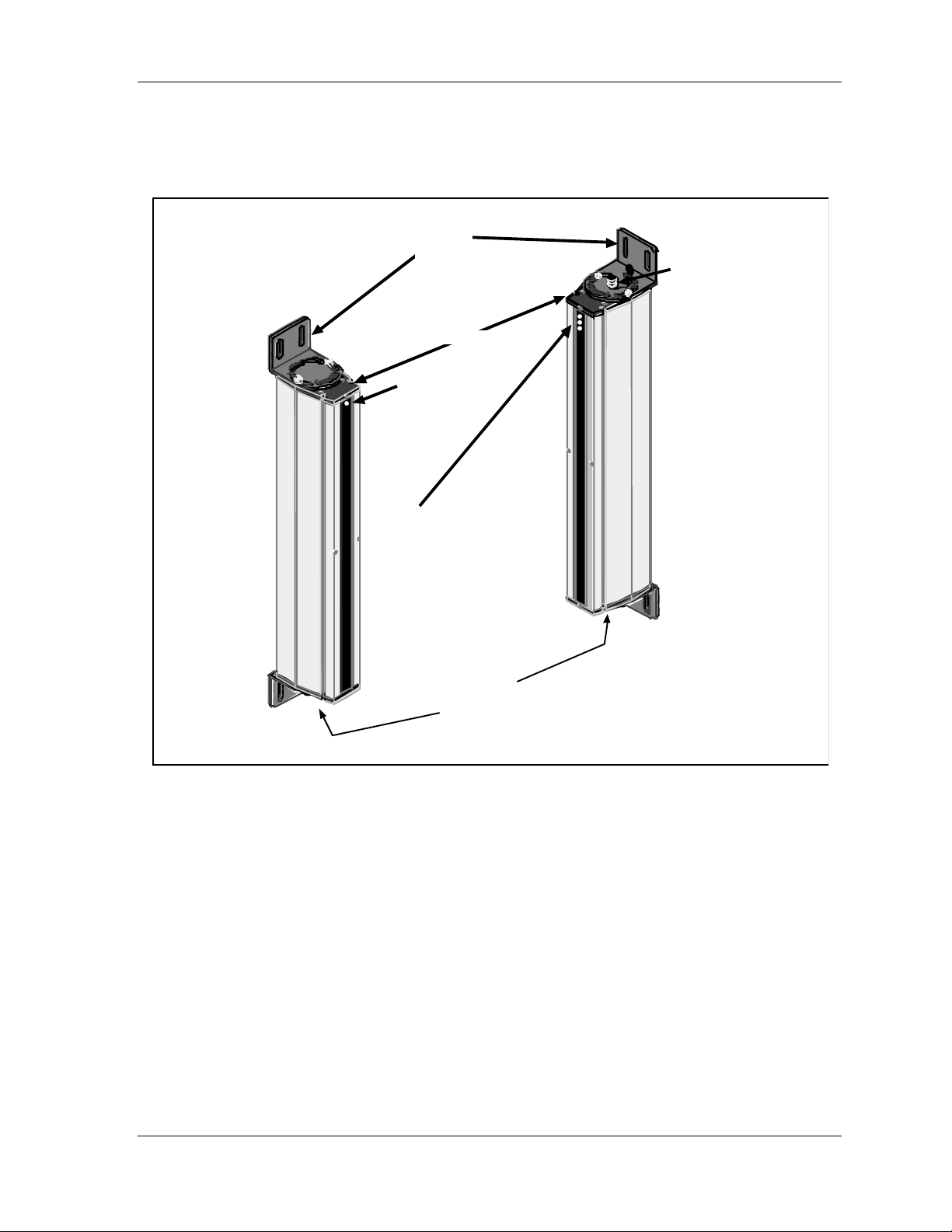
The optic heads are constructed of rugged, heavy-gauge extruded aluminum (0.12-inch wall
thickness). These compact heads (2" x 2.85" cross-section) come in sizes ranging from 6
inches to 5 feet in height. The transmitter and receiver (see Figure 1-1) are optionally
available in explosion-proof enclosures.
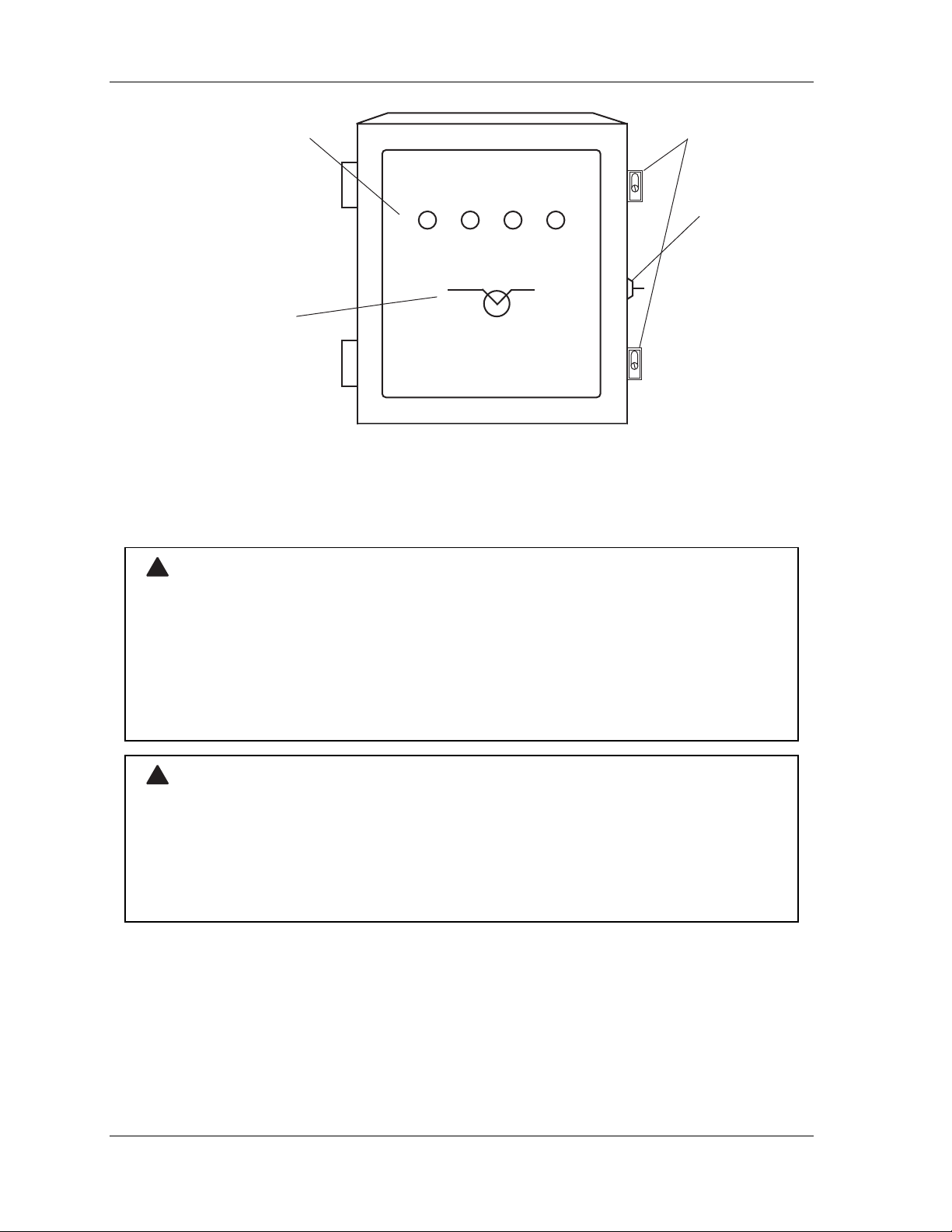
Shadow also includes a control enclosure (Figure 1-2) to which any-sized receiver and
transmitter can be wired. No special settings are required. The control contains a power
supply, relay circuitry, and switch block assemblies where you can easily enable or disable
Shadow's options.
For added security, the control comes standard with an enclosure keylock and a reset
keyswitch. Simply turn the reset keyswitch to the right when resetting is required.
page 2 Chapter 1 Introduction to Shadow VI
Safety Light Curtain
Page 15
Shadow VI User Manual 1107200
A
The cables join the control with the transmitter and receiver and are interchangeable between
each optic head. These cables have connectors that plug into the optic head end and screw
terminations that connect at the control end. They come in various lengths.
universal
mounting
Transmitter
brackets
end caps
LED:
mber
(power on)
mating connector
for blanking
window cable
Receiver
LEDs:
Red
(cu rtain obstructed)
Orange
(floating window enabled)
Green
(curtain unobstructed)
"quick-connect"
cable connectors
Figure 1-1. Illustration of Shadow Transmitter and Receiver
Introduction to Shadow VI Chapter 1 page 3
Safety Light Curtain
Page 16
1107200 Shadow VI User Manual
LED Indicators for
cover latches
curtain clear,
floating window enabled,
curtain blocked and
reset required
CURTAIN
CLEAR
FLOATING
WINDOW
STOP
SIGNAL
RESET
REQUIRED
enclosure
keylock
RESETOPERATE
reset keyswitch
(key pointed
toward "operate"
during normal
operation)
LIGHT CURTAIN
Figure 1-2. Illustration of Shadow Control
How Shadow Works
!
WARNING
IMPROPER INSTALLATION
• Connect the Shadow safety light curtain stop relays to the machine’s stop circuit. If you do
not use the stop relays, you will not have the maximum protection afforded by these light
curtains.
• DO NOT attempt to connect Shadow safety light curtains to any control until you have
carefully read the installation instructions.
Failure to comply with these instructions could result in death or serious injury.
!
WARNING
UNPROTECTED MACHINERY MAY CONTINUE TO OPERATE
Ensure that all operators know which device(s) your Shadow safety light curtain protects and
which it does not. The press Shadow is wired to will stop when the light curtain is
interrupted and sends a stop signal to the press. However, the associated feeds and
conveyors, to which Shadow is not wired, will continue to operate after the press stops.
Failure to comply with these instructions could result in death or serious injury.
You cannot see the actual light curtain emitted by Shadow. However, the invisible curtain of
light automatically prevents access to hazardous areas while the press is operating.
page 4 Chapter 1 Introduction to Shadow VI
Safety Light Curtain
Page 17
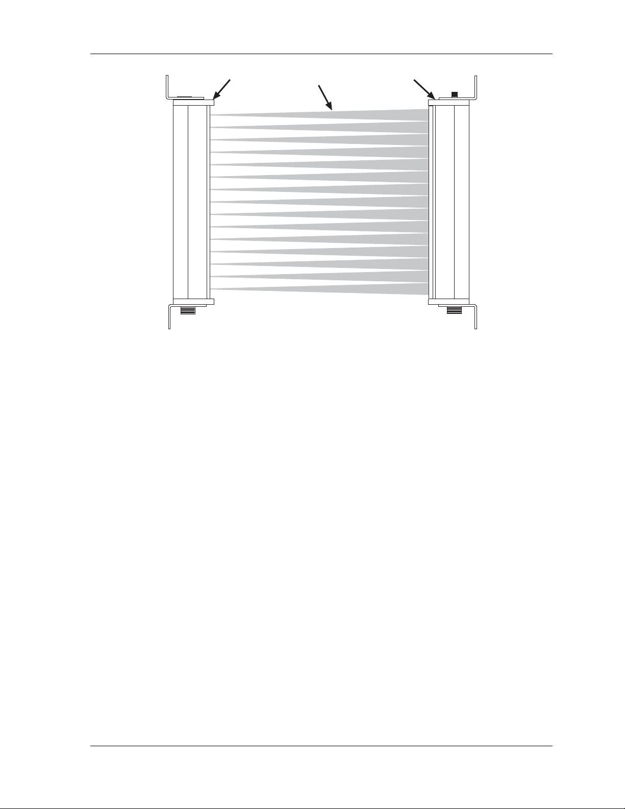
Shadow VI User Manual 1107200
transmitter
light beams
receiver
Figure 1-3. Showing Light Beams with Shadow Light Curtain
Shadow's transmitter and receiver are not "matched sets". In other words, a Shadow VI
transmitter will work with any same-sized Shadow VI receiver. You mount the units on the
machinery on either side of the hazardous area.
Shadow can be described as an optoelectronic presence-sensing device. Presence-sensing
means the light curtain detects an object that penetrates its field and reacts to it by signaling a
press to stop when an intrusion occurs. Optoelectronic means Shadow works using light and
electric current.
The transmitter's LEDs (light emitting diodes) emit a harmless, invisible, infrared light pulse
when an electrical pulse passes through them. These LEDs transmit light towards the
receiver. The receiver's phototransistors detect each light pulse and produce an electrical
signal whenever the light pulse hits them. An invisible light barrier is formed by infrared
light beams sent from the transmitter to the receiver. Reacting to the loss of light, Shadow
sends a stop command to the press when there is an obstruction, such as when you put your
hand into the light field.
As the light curtain is operating, each transmitter LED pulses in succession from top to
bottom, in the form of a conical beam. The phototransistors in the receiver detect these light
pulses instantly and produce an electrical signal (turn on) when the light strikes them. Each
phototransistor detects the one pulse of light designated to it. It is only enabled at the instant
that the beam is anticipated. Shadow's electronics must "see" the phototransistor turn "on"
then "off" as the beam hits it and disappears. Each phototransistor must turn on, then off in
sequence, or Shadow will send a stop command to the machinery.
Introduction to Shadow VI Chapter 1 page 5
Safety Light Curtain
Page 18
1107200 Shadow VI User Manual
Because the receiver only accepts infrared light pulses of a certain duration in proper
sequence, Shadow cannot be affected or fooled by other light sources. All other continuous
light sources and even pulsed light sources are "tuned out." Therefore, the light curtain is not
affected by normal lighting near the light curtain. Also, changes in area lighting or even
flashing strobe lights will not affect operation.
This pulsed sequence is so fast that, where we mark time in units no smaller than a second,
the effect is a continuous light field across the guarded area. You would have to move the
point of your finger across an LED in the transmitter in less than 5/1000th of a second (5 ms
or milliseconds) to evade the light pulses coming from that LED. Therefore in our world of
seconds and minutes, the light curtain is really always there even though only one light beam
is actually produced at a time. The actual light pulse lasts for only 1/100,000th of a second
(10 microseconds). Consequently it does not take long to create a whole series of pulses one
after the other.
Shadow and Control Reliability
!
WARNING
IMPROPER INSTALLATION
• Install Shadow safety light curtains in compliance with applicable safety regulations from the
Occupational Safety and Health Administration (OSHA) and the American National
Standards Institute (ANSI). See excerpts in the appendices.
• Refer to the latest revision of all applicable documents.
• Ensure that your installation meets the control reliability requirements of the applicable
regulations.
• Ensure that both Shadow control relays are used in any Shadow installation, including
connection directly to the press control's stop circuit, to a PLC, or to other type of machine
control. Wiring is explained in Chapter 2.
• Read carefully and understand the installation instructions before attempting to install and
wire Shadows to any control
• Ensure that installation is performed by qualified personnel.
Failure to comply with these instructions could result in death or serious injury.
!
WARNING
UNPROTECTED MACHINERY MAY CONTINUE TO OPERATE
Ensure that all operators know which device(s) your Shadow safety light curtain protects and
which it does not. The press Shadow is wired to will stop when the light curtain is
interrupted and sends a stop signal to the press. However, the associated feeds and
conveyors, to which Shadow is not wired, will continue to operate after the press stops.
Failure to comply with these instructions could result in death or serious injury.
Shadow is control reliable. Control reliability is a term used and defined in the same way by
the Occupational Safety and Health Administration (OSHA) and the American National
Standards Institute (ANSI).
page 6 Chapter 1 Introduction to Shadow VI
Safety Light Curtain
Page 19

Shadow VI User Manual 1107200
NOTICE
The Occupational Safety and Health Administration (OSHA) and the American National
Standards Institute (ANSI) have issued regulations for the use of presence-sensing devices
such as Shadows. Both of them require control reliability. See Appendix A for more
information.
Control reliability means "the device shall be constructed so that a failure within the system
does not prevent the normal stopping action from being applied to the press when required,
but does prevent the initiation of a successive stroke until the failure is corrected."
Control reliability is another reason why Shadow is an excellent machine guard. All critical
components in Shadow are duplicated so that if one fails, the other will still allow normal
operation to stop the machinery. If a component failure does occur, Shadow will immediately
detect the failure and send a stop signal to the machinery. The light curtain will not allow
operation until the repairs are made.
Another example of control reliability are Shadow's control relays. The control contains
captive-contact relays (2 stop and 1 status relay). The N/O outputs are connected in series to
the press's emergency stop circuit and are always energized (contacts held closed) when the
light field is not broken. When an obstruction enters the field, Shadow's control circuitry
instantly de-energizes the relays, which results in opening the contacts and breaking the stop
circuit of the press. Shadow's response time from loss of light to relay contacts open is 30 to
40 milliseconds (depending on the size of the optic heads). Even if one of Shadow's control
relay contacts fails closed (contact welds shut), the second relay will still de-energize and a
stop signal will be sent to the machinery. Shadow will also detect the failed relay. It will not
allow further press operation until the relay is replaced. It is highly unlikely that the relay
contacts will fail simultaneously.
Description of Shadow VI indicators
Shadow includes several indicators. Figure 1-1 shows the indicators on the transmitter and
receiver, and Figure 1-2 illustrates the control.
These indicators communicate Shadow's operating status. Use them to troubleshoot your
light curtain (see Chapter 4 troubleshooting guides). If any contradiction exists between the
indicator lights at the receiver and those at the control, make sure you compare your findings
with the information in these troubleshooting guides to solve the problem immediately.
At the Optic Heads
The transmitter has an amber-colored power indicator which remains illuminated when
Shadow has power. There are three indicators on the front of the receiver. The red
indicator means that the light curtain has been interrupted. The orange indicator flashes
when the floating window option is turned "on" at the control (see Chapter 2). The green
indicator means the light curtain is unobstructed.
Introduction to Shadow VI Chapter 1 page 7
Safety Light Curtain
Page 20

1107200 Shadow VI User Manual
At the Control
Four indicators appear on the front cover of the control and are clearly labeled. The green
"curtain clear" indicator means that the light curtain is unobstructed and the machinery will
be allowed to operate (the control relay contacts are held closed or in the unobstructed/
energized state). The "floating window" indicator lights up amber when this blanking
feature is enabled inside the control (see Chapter 2). The "stop signal" indicator goes red
when the light curtain is obstructed, the control relay contacts are open (or in the deenergized
state) and the press is disabled, if there is misalignment, or when Shadow has detected an
internal malfunction. The yellow "reset required" signifies that a “reset required” or
condition exists. This could occur during power-up if “power up reset” settings are
enabled at the control (see Chapter 2), or if Shadow detects an internal malfunction with any
of the components (transmitter, receiver, or control).
Inside the Control
There are four indicators inside the control (refer to Figure 2-14 in Chapter 2 for location of
components). DS1 and DS2 are red indicators that are located just above the TB2 receiver
connectors at the lower right-hand corner of the board. They light up red if you are using
only 1 set of optic heads and there is an obstruction, misalignment, or internal problem. If
you have 2 sets, DS1 lights up red when Set 1 (wired to the upper connectors of TB2 and
TB3) is interrupted, the optic heads are misaligned, or an internal problem exists. DS2
corresponds with Set 2, which are wired to the lower connectors. Refer to the
troubleshooting guides in Chapter 4 for more details.
DS3 and DS4, located in the upper right-hand corner of the control near the power supply,
light up green all the time to indicate that power is going to the receiver and transmitter
respectively.
Chapter 4 provides troubleshooting guides which reference the indicators at the control and
the optic heads. They suggest how to solve a problem with the light curtains when certain
conditions exist.
Object Sensitivity
Object sensitivity is the minimum diameter object that Shadow can detect. Object sensitivity
for Shadow is 1
larger anywhere in the sensing field. Shadow light beams are on 3/4" (1.9 cm) centers. An
object smaller than 1
in a path directly between the light beams.
1/4" (3.2 cm), which means that it will detect any object of this diameter or
1/4" diameter could pass undetected through the light field if it traveled
Size and Scanning Distance
Shadow is available in a wide array of standard sizes from 6" to 60". Shadow's standard
scanning distance is 25 feet (7.6 meters), and optionally 50 feet (15.3 meters). The "standard
range" units cannot be modified for "extended range" capability.
page 8 Chapter 1 Introduction to Shadow VI
Safety Light Curtain
Page 21

Shadow VI User Manual 1107200
Shadows Are Easy to Maintain
No adjustment or maintenance is required. It continues working silently. You only need to
replace fuses or relays as needed (described in Chapter 4). You should, however, clean the
lens window(s) periodically if the working environment is particularly dusty, dirty, oily or
smoky. A heavy build-up of dirt or oil could jeopardize Shadow's efficiency by blocking a
light beam and cause an inadvertent press shutdown. You should also periodically verify
proper alignment. Alignment is discussed in Chapters 2 and 4.
Introduction to Shadow VI Chapter 1 page 9
Safety Light Curtain
Page 22

1107200 Shadow VI User Manual
Shadow VI Features and Options
Shadow is designed for uncompromising safety and durability under real world conditions.
The light curtain includes various features and options. Some of these are described next.
The floating window feature provides a means for the random bypass of only one beam of
the light curtain. It is useful in those applications where material must travel through or
within the sensing field in a random pattern. The floating window may only be used when
material or parts take up a space no greater than 1
Larger material would block more than one light beam at a time which would generate a stop
command. This built-in feature is enabled by turning a switch "on" at the control. The
amber indicators at the receiver and on the front cover of the control flash when floating
window is "on". A floating window automatically alters the object sensitivity from 1
2". If you plan to use this feature even occasionally, the safety distance for mounting must
be increased. Refer to "Calculating Safety Distance" in Chapter 2 of this manual.
Shadow has optional fixed blanking capability. External blanking windows (purchased
separately) allow you to disable up to 5 contiguous beams in an area where a fixture
penetrates the light field and permits stationery objects to protrude into Shadow's sensing
field. For example, in a situation where a conveyor or work table extends into this field,
moving the fixture may not be feasible. Therefore, you install a blanking window on the
Shadow receiver where the fixture penetrates the field. This disables the light beam that
would normally detect the fixture. However, if the light field is penetrated in any area above
or below the fixture (or "blanked" light beam), the light curtain will send a stop signal to the
machinery.
1/8" (2.9 cm) within the sensing field.
1/4" to
Floating window can be used in conjunction with fixed blanking. An example could be an
application where part of the tool physically protrudes into the light field and an air blow-off
is randomly ejecting parts. Floating window is covered in Chapters 2 and 3, and fixed
blanking is discussed in Chapter 3. Safety distance is also affected by fixed blanking
window if the fixed obstruction does not extend all the way from the transmitter to the
receiver. See Chapter 2 for a comprehensive discussion of safety distance.
Shadow has passed stringent environmental stress tests for shock, vibration, impact, exposure
to temperature extremes, dust, humidity, and electrical abnormalities.
Shadow comes with a built-in status relay which can be set to perform different functions
(setup is covered in Chapter 2). When wired to the main motor, the relay opens at power-up
if “reset on power up” has been enabled at the control (see "Making settings" in Chapter 2).
The status relay can be set to "mimic" stop outputs which can activate an alarm or beacon
whenever Shadow is in a "stop signal" (red) condition.
Shadow can also be used in perimeter guarding applications when there is a walk-in hazard
inside the guarded area. In this case, a "stop signal" condition is generated when any of the
light curtain beams has been obstructed. Shadow will not reset to "curtain clear" (green)
automatically even when the obstruction has been removed. You must reset the system to
resume operation. Activating this feature is discussed in Chapter 2.
Both Shadow optic heads include universal mounts. These mounts are used to properly align
the Shadow heads during installation. They can be rotated ±30° to make installation and
page 10 Chapter 1 Introduction to Shadow VI
Safety Light Curtain
Page 23

Shadow VI User Manual 1107200
alignment easier. By rotating the brackets 90° with respect to the head, they provide
additional flexibility when mounting. Installing the universal mounts is covered in
Chapter 2.
Weld Shield Kit
Shadow's operation is not affected by smoke, dirt, or oil found in a typical industrial
environment. If necessary, however, you can at any time install replaceable shields to
provide protection from weld splatter and other hazards. Weld shields are clear plastic
covers that fit on the face of the transmitter and/or receiver. They come in kits ready for
installation, and can be easily replaced if they become so damaged or scratched that the light
curtain no longer indicates “green” during normal operation. (See the Troubleshooting Guide
in Chapter 4 of this manual).
Refer to Chapter 2 of this manual for more information about using weld shields.
Introduction to Shadow VI Chapter 1 page 11
Safety Light Curtain
Page 24
1107200 Shadow VI User Manual
Table 1-1. Shadow VI Specifications
!
WARNING
INDICATOR OUTPUTS NOT SUITABLE FOR SAFETY USE
• DO NOT use the indicator outputs listed in the specifications table for personnel protection.
They cannot be used to stop the machinery.
• Use the safety outputs for personnel protection.
Failure to comply with these instructions could result in death or serious injury.
Scanning heights 9 models: 6, 12, 18, 24, 30, 36, 42, 48 and 60 inches
Scanning range Standard: up to 25 ft (7.6 m)
Beam spacing
Object sensitivity 11/4" (3.2 cm)
(15.2, 30.5, 45.7, 61.0, 76.2, 91.4, 106.7, 121.9, and 152.4 cm)
Extended: up to 50 ft (15.3 m)
Transmitter and receiver not matched sets
3
/4" (1.9 cm) centers
Response time 30 msec max. for 6" to 24"
35 msec max. for 30" to 48"
40 msec max. for 60"
Size
Optic heads
Control enclosure
See Figures 2-4, 2-5, and Table 2-1 in Chapter 2.
7" x 9" x 3.5" (17.8 x 22.9 x 8.9 cm). See Figure 2-13 in
Chapter 2.
Weight
6" optic heads
Control
Construction
Heads
Control
Cables
Environmental
Heads
Control
Cables
1.4 lbs (.64 kg) ; add 0.9 lbs (.4 kg) for every additional
6 inches in height
9 lbs. (4 kg)
Extruded aluminum; 0.12" (3 mm) wall min
18-gauge welded steel with enclosure keylock.
5, 15, 25, 50, and 100 ft. with connector at the optic head.
NEMA 4, IP65; Optional explosion-proof enclosures.
NEMA 2 / IP52; Optional NEMA 4/IP65; Optional with 4
connectors for 2 sets of optic heads; Optional explosionproof enclosure.
NEMA 4 connector; Oil-resistant PVC cable standard;
Optional SJOOW cable with 1 or 2 connectors.
Vibration
10g, 0.03" displacement; freq. 10-150 Hz sine, per UL491
(applies to all three axes).
page 12 Chapter 1 Introduction to Shadow VI
Safety Light Curtain
Page 25

Shadow VI User Manual 1107200
Shock testing 50g, 11ms pulse per MIL-STD-810 C, Method 516,
Procedure I (applies to all three axes).
Operating Temperature - 4° F to 122° F (-20° to 50° C).
Inputs
Power
Heads
MPCE
Remote Reset
115-230 VAC (DC available)
50-60 Hz; 30 VA max.
Two sets (any height) can be connected to same control.
Monitor input: For external dry contacts rated at 20 mA @
20 VDC; 25 msec. response time max.
Closure to ground ON voltage 2V @ 2mA
Light Source Infrared light emitting diodes (LEDs).
Approximately 850 nanometer wavelength
Optics Angle of Divergence and Acceptance: less than ± 3.5°.
Outputs
Stop Circuit/status
Indicator Outputs*
2 "captive contact" stop relays and one status relay, plus 4
solid state indicator outputs.
4A @ 120 VAC or DC resistive max; N/O and N/C
contacts with all 3 relays.
4 open collector, NPN, opto-isolated outputs can switch
70 V load @ 2 mA maximum (see warning below).
Indicators
Transmitter
Receiver
Amber (power).
Red "obstructed"; Amber "floating enabled"; Green "clear
unobstructed".
Control
Red "obstructed"; Amber "floating enabled"; Green "clear
unobstructed"; Yellow "Reset required".
Introduction to Shadow VI Chapter 1 page 13
Safety Light Curtain
Page 26

1107200 Shadow VI User Manual
Table 1-2. Shadow options and functions
OPTION FUNCTION
Mirrors Provide 2 or 3-sided protection; each mirror reduces effective
scanning distance by 10%.
Blanking Windows Electronics for blanking standard; external blanking windows
must be purchased separately; maximum number of blanked
beams is 5.
Floating Window Allows objects smaller than 11/8" to move through light field
without interrupting operation. One beam floating capability
built-in; enabled at control.
Weld shield kits Specify the model size of your Shadow.
See Chapter 2 for more information.
Laser Alignment Tool For optimum alignment; uses 3V Lithium battery.
Interchangeability Transmitter and receiver are not matched sets; Shadow VI
transmitter can be used with Shadow VI receiver of same.
page 14 Chapter 1 Introduction to Shadow VI
Safety Light Curtain
Page 27

Chapter 2 – Installation and Checkout
!
DANGER
IMPROPER INSTALLATION, USE OR MAINTENANCE
• Follow all procedures in this manual. This is required for proper operation of the light
curtain.
• Ensure that the light curtain is installed so it is impossible for anyone to reach over, under, or
around the light curtain and into the hazardous area of the machine without being detected.
Use the correct height light curtain, combined with ancillary physical guards.
• Install and maintain your machine guarding system according to OSHA standard 1910.212
and any other regulations and standards that apply.
• Wire and install Shadow safety light curtains in accordance with the requirements of OSHA
lockout/tagout regulation 1910.147.
• Ensure that Shadow safety light curtains are installed, tested and repaired by qualified
personnel.
• Perform only the tests and repairs listed in this manual.
• Test the operation of your Shadow safety light curtains daily using the checkout sequence
shown on the Shadow safety light curtain units and also listed in this manual. If your Shadow
safety light curtains are installed so the warning and test procedure labels are not clearly
visible, call the factory for extra warning labels to attach to your machinery in a highly visible
area.
• Perform the checkout sequence after any maintenance is done on the Shadow safety light
curtains.
• Ensure that supervisors, die-setters, maintenance persons, machine operators, foremen, or
any others responsible for the proper operation of the machinery have read and understood
all instructions for use of the Shadow safety light curtains.
Failure to comply with these instructions will result in death or serious injury.
Installing Shadow is a straightforward procedure. You must proceed carefully, however,
since the Shadow VI light curtain is a safety device which protects press operators and other
personnel.
Check that you received everything. With Shadow, you should have received optic heads
(transmitter and receiver), a control (the "third box"), and two interchangeable quick connect
cables, one for each optic head (required cable lengths specified at time of order). If you are
missing any of these, contact Wintriss Tech Support immediately before proceeding with the
installation. Before you start the installation, read the instructions thoroughly. Then proceed
carefully to be ensure proper installation and operation.
A brief general overview of the installation procedure is listed first in this chapter. After
reading the overview, follow the more detailed installation instructions that come next. The
actual instructions must be followed for proper installation of Shadow VI.
Shadow VI User Manual 1107200
Installation and Checkout Chapter 2 page 15
Page 28

1107200 Shadow VI User Manual
Installation overview
Read this overview before beginning the installation procedures that follow. It will
familiarize you with the steps required to complete the installation.
Calculating the safety distance
The proper distance that the Shadow heads must be mounted away from the pinch point (or
hazardous area) is calculated. This is called the safety distance. This distance allows enough
time for Shadow to react, and the press to stop, before an intrusion, like the operator's hand,
reaches the pinch point. The pinch point is the area of the press where moving parts can
cause injury. The safety distance can be calculated precisely using the formula explained in
the section "Calculating the safety distance".
Mounting location for your Shadow transmitter and receiver
A mounting location is selected. Rigid mounting brackets are fabricated and attached to your
press. Brackets are used to bring the Shadow heads out to the proper safety distance and to
allow proper alignment.
Wiring, aligning, mounting, and making proper settings
The Shadow light curtain optic heads are mounted to the brackets using shock mounts, then
aligned, and wired to the control, which is then wired into your press's control circuitry.
Proper settings are made at the Shadow’s control to enable its features and options.
The standard control enclosure is rated NEMA 2/IP52. You must use conduit of the same
rating and make proper connections to ensure proper protection with the enclosure. If you
have an optional NEMA 4/IP65 enclosure, suitably rated conduit hubs must be used on all
unused holes in the control enclosure to maintain proper NEMA 4/IP65 rating.
Ensuring that the Shadow light curtains are working properly
Perform the checkout sequence after installation to ensure that Shadow VI is working
properly.
page 16 Chapter 2 Installation and Checkout
Page 29
Shadow VI User Manual 1107200
Installation Procedure
!
DANGER
FAILURE TO PERFORM SAFETY SYSTEM TESTS
• Perform the final checkout sequence below when you have completed installation of your
light curtain, before operating the equipment it is connected to.
• Operate your machinery only after your safety system meets all the requirements of the
checkout sequence.
• Perform the final checkout sequence whenever repair, maintenance or modification is
performed on your light curtain or the machinery it is connected to.
• Perform the “daily test” safety system checkout sequence on page 93 (in French, en
Français, page 114) every day before operating any machinery connected to Shadow safety
light curtains.
Failure to comply with these instructions will result in death or serious injury.
!
WARNING
ELECTRIC SHOCK HAZARD
• Turn off and disconnect power from the Shadow safety light curtain and from the machinery
it is connected to before making any wiring connections. This includes disconnecting power
to the machine control and motor.
• Remove all fuses and “tag out” per OSHA 1910.147 Control of Hazardous Energy
(Lockout/Tagout).
• Ensure that installation is performed by qualified personnel.
Failure to comply with these instructions could result in death or serious injury.
The installation procedure is divided into these steps:
• Calculating the safety distance
• Designing and mounting brackets
• Loosely mounting Shadow VI heads
• Mounting the control
• Wiring the transmitter and receiver to the control
• Connecting AC wiring to the control
• Connecting stop circuits to the control
• Making settings inside the control
• Aligning and tightening down Shadow VI components
• Diagnostic steps to perform before Shadow operation
• Final checkout sequence
It is a good idea to read over the complete installation procedure before starting. This will
guide you about the materials and techniques required for making and positioning mounting
brackets and aligning Shadow VI heads.
Installation and Checkout Chapter 2 page 17
Page 30
1107200 Shadow VI User Manual
Calculating the Safety Distance
!
DANGER
INCORRECT SAFETY DISTANCE
• Calculate the safety distance carefully according to the instructions below, and mount your
light curtain heads at least this distance from the hazardous area.
• Mount your light curtain heads at least 7.5” (191 mm) from the hazardous area, regardless
of the calculated safety distance.
Failure to comply with these instructions will result in death or serious injury.
!
DANGER
INCORRECT SAFETY DISTANCE DUE TO BLANKING OR FLOATING WINDOWS
• Read “Chapter 3 – Fixed and Floating Blanking” before calculating the safety distance. This
chapter tells how to modify the safety distance when you use windows.
• Modify the safety distance calculated with the instructions below, as required.
Failure to comply with these instructions will result in death or serious injury.
!
DANGER
INCREASED SAFETY DISTANCE DUE TO BLANKING OR FLOATING WINDOWS
Modify the safety distance between the light curtain and the hazardous area according to the
instructions in this chapter and in Chapter 3, "Floating and Blanking Windows."
Failure to comply with these instructions will result in death or serious injury.
!
DANGER
INCORRECT SAFETY DISTANCE DUE TO LONGER RESPONSE TIME
Determine which model Shadow safety light curtains you have. Use the correct response
time for your model light curtain in your safety distance calculations. Safety depends on your
installing your light curtain at the correct safety distance from the hazardous area.
12” to 24” 30 ms response time
Failure to comply with these instructions will result in death or serious injury.
!
DANGER
STOPPING TIME TOO LONG
Use a brake monitor where a Shadow light curtain is used to protect operators whose hands
are routinely exposed to a hazardous area, as required by OSHA 1910.217 (c) (3) (5). A
brake monitor continually checks that the machine’s stopping time does not exceed a
predetermined limit.
Failure to comply with these instructions will result in death or serious injury.
36” to 48” 50 ms response time
page 18 Chapter 2 Installation and Checkout
Page 31
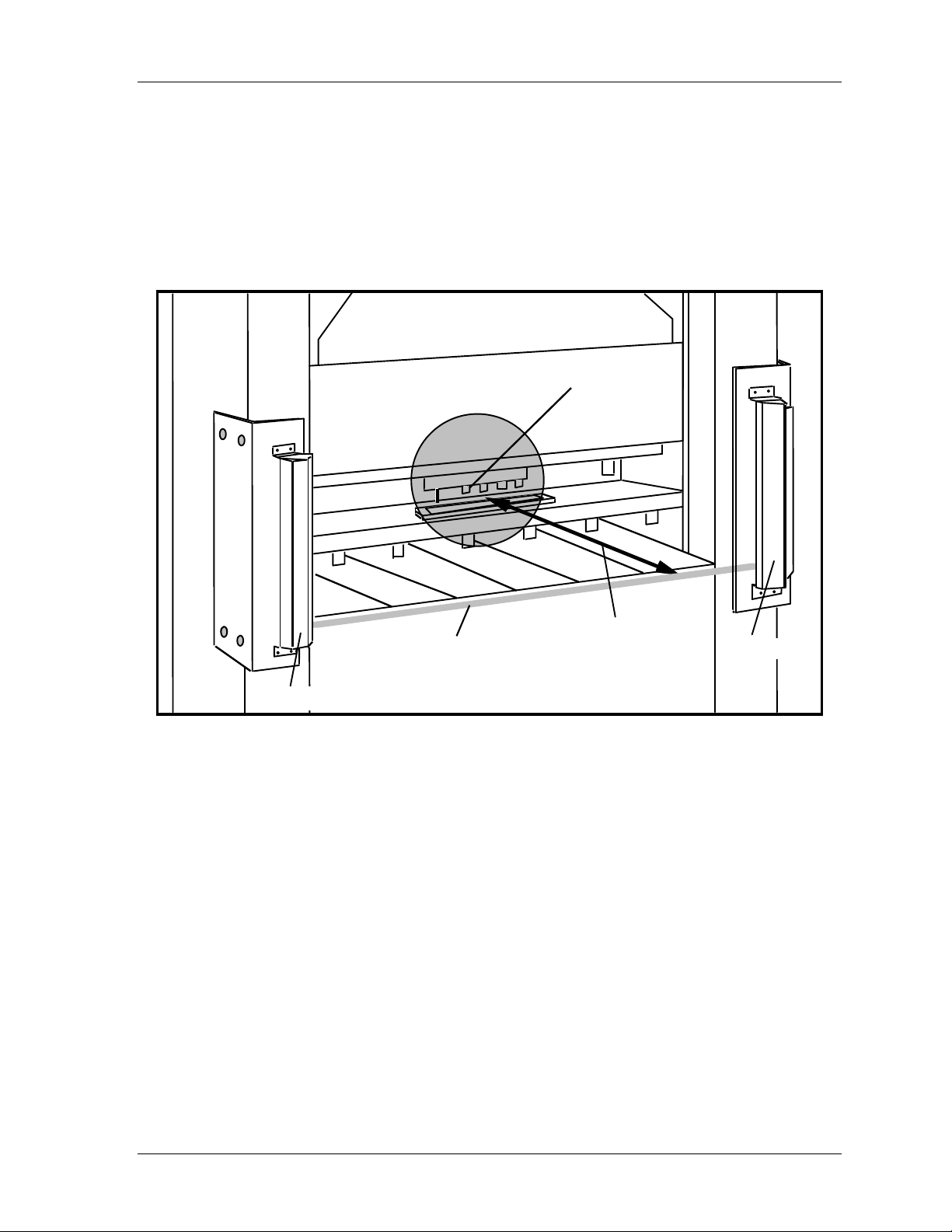
Shadow VI User Manual 1107200
r
r
r
Shadow light curtains must be mounted away from the pinch point (or hazardous area) of the
press at a specific distance. This distance is based on the stopping time of your press. This
distance is called the safety distance. It must be calculated using a precise formula. This
ensures that Shadow VI can send the stop signal to the press, and the press will stop, before
the operator's hand reaches the hazardous area.
This next illustration shows how you would measure the distance between the pinch point (or
hazardous area) of your press and the light curtain.
pinch point
Distance between
One oflight curtain's
invisible light beams
transm itter
light cu
pinch point
tain and
eceive
Figure 2-1. Distance Between Pinch Point and Light Curtain
This distance must be greater than the calculated safety distance or Shadow may not be
able to stop the press before an operator's hand reaches the hazardous area.
OSHA and ANSI Requirements
All machine safeguarding devices, including Shadow VI, must be located at the correct
safety distance from the pinch point or hazardous area. OSHA regulations govern the
mounting of infrared light curtains when used with mechanical power presses
(OSHA 1910.217). The OSHA formula has been used as a guide in other applications since
there has not been a well-known formula for safety distance which governs general machine
guarding.
When calculating safety distance, Wintriss, on the other hand, recommends that you use the
formula from ANSI B11.1-2009. This formula represents a new consensus on the proper
installation of light curtains. ANSI B11.1 has been developed specifically for guarding of
mechanical power presses. However, it should be used as a guide in other applications as
Installation and Checkout Chapter 2 page 19
Page 32
1107200 Shadow VI User Manual
well. For complete information on OSHA regulation 1910.217 and ANSI standard
B11.1-2009, see the Appendix, found at the end of this manual.
Both the ANSI and OSHA formulas are explained below. If you need assistance in
calculating the safety distance, call Wintriss Tech Support.
The OSHA Safety Distance Formula
!
DANGER
INCORRECT SAFETY DISTANCE
• Calculate the safety distance carefully according to the instructions below, and mount your
light curtain heads at least this distance from the hazardous area.
• Mount your light curtain heads at least 7.5” (191 mm) from the hazardous area, regardless
of the calculated safety distance.
• Be sure your value for Ts includes the response times of all devices that react to stop the
press. If your measurement of stop time does not include response time of the press control,
light curtain, and any other devices that react to stop the press, the safety distance will be
too short.
Failure to comply with these instructions will result in death or serious injury.
!
DANGER
STOPPING TIME TOO LONG
Use a brake monitor where a Shadow light curtain is used to protect operators whose hands
are routinely exposed to a hazardous area, as required by OSHA 1910.217 (c) (3) (5). A
brake monitor continually checks that the machine’s stopping time does not exceed a
predetermined limit.
Failure to comply with these instructions will result in death or serious injury.
The OSHA safety distance formula as specified in OSHA regulation 1910.217 is explained
below. As noted earlier, Wintriss recommends you use the American National Standards
Institute formula for calculating safety distance because it contains more factors that allow
you to calculate the safety distance more precisely. The ANSI formula is explained in the
next section.
Here is the OSHA safety distance formula as specified in OSHA 1910.217:
Ds = 63 inches/second x T
s
63 inches-per-second is the OSHA-recommended hand-speed constant.
Ds is OSHA safety distance in inches
Ds = 63 x T
T
is the stopping time of the press (or other machine) in seconds, measured at approximately
s
90° of crankshaft rotation (or at maximum velocity). T
s
must include: all components that are
s
involved in stopping the press; response time of the press control that activates the brake and
response time of the light curtain (30 ms for 6" through 24" models; 35 ms for 30" through
48" models; 40 ms for the 60" model); plus response time of other devices if also involved in
stopping the press.
page 20 Chapter 2 Installation and Checkout
Page 33

Shadow VI User Manual 1107200
Since some increase in stop time can invariably be anticipated due to clutch/brake system
deterioration, a percentage factor must also be added to the actual measured stop time of your
press when determining your safety distance.
A percentage factor of 20 percent is recommended for presses with new brakes or brakes in
good condition; a percentage factor of 10 percent is recommended for presses with older
brakes. This is because the stopping time for older brakes will be longer due to wear.
Therefore, you add less time for older brakes.
An example of calculating the safety distance using the OSHA formula
The OSHA formula for finding safety distance is: Ds = 63 inches/sec. x Ts
We will use a stop time of .190 seconds for this example. This includes reaction time of all devices
noted above in signaling the press to stop except the response time of the light curtain. Next we will
add in Shadow VI response time and the braking percentage factor. Let's say our brakes are new.
Then we will add 20% additional time to the stop time measurement (.20 x .190 = .038). We also add
response time of the 60” Shadow VI (.040 seconds). Then:
Ts = .190 sec. + .038 sec + .040 sec.
(braking factor) (Shadow VI response time)
Ts = .268
Now, we will calculate safety distance:
Ds = 63 in/sec x Ts
Ds = 63 x .268
Ds = 16.88 in.
Shadow VI heads must be mounted more than 16.88 inches from the hazardous area using the
OSHA formula.
The ANSI Safety Distance Formula
!
DANGER
INCORRECT SAFETY DISTANCE
• Calculate the safety distance carefully according to the instructions below, and mount your
light curtain heads at least this distance from the hazardous area.
• Mount your light curtain heads at least 7.5” (191 mm) from the hazardous area, regardless
of the calculated safety distance.
• Be sure your value for Ts includes the response times of all devices that react to stop the
press. If your measurement of stop time does not include response time of the press control,
light curtain, and any other devices that react to stop the press, the safety distance will be
too short.
Failure to comply with these instructions will result in death or serious injury.
Installation and Checkout Chapter 2 page 21
Page 34

1107200 Shadow VI User Manual
!
DANGER
STOPPING TIME TOO LONG
Use a brake monitor where a Shadow light curtain is used to protect operators whose hands
are routinely exposed to a hazardous area, as required by OSHA 1910.217 (c) (3) (5).
A brake monitor continually checks that the machine’s stopping time does not exceed a
predetermined limit.
Failure to comply with these instructions will result in death or serious injury.
This is the ANSI B11.1 safety distance formula that Wintriss recommends:
Ds = 63 x (Ts + Tc + Tr + Tbm) + Dpf
Ds is the ANSI safety distance in inches.
K is the OSHA-recommended hand-speed constant. This constant is 63 inches-per-second.
The hand-speed constant indicates how far you could theoretically move your hand and arm
in one second.
It is very similar to OSHA's formula, except that it takes more details (such as response
times, brake monitoring setting, and depth penetration factor) into account. Ts, Tc, and Tr
are the worst case response times of the press (or other machine) T
, the control T
s
, and the
c
light curtain Tr.
T
is the stopping time of a press (or other machine) in seconds. It is measured at
s
approximately 90° of crankshaft rotation (or at maximum closing velocity).
Tc is the response time of the press control or other machine control. This is the time it takes
for the control to activate the press's brake.
Tr is the response time of the light curtain. Response time for the Shadow VI is 30 to 40 ms
(30 ms for 6" to 24” models, 35 for 30” to 48” models and 40 ms for the 60” model).
Tbm is the additional stopping time of the press (or other machine) allowed by the brake
monitor. The brake monitor you use with your press control (or other control) stops the press
when the preset stop time is exceeded. This means excessive brake wear has occurred. It is
time for repair. The brake gradually wears until the limit is reached.
Tbm allows you to account for brake wear. You add the extra time allowed by the brake
monitor to Tc and Ts. In other words:
Tbm = brake monitor setting — (Tc + Ts)
Now the gradual increase in stopping time as the brake wear is accounted for up to the limit.
What if you did not account for brake wear? The safety distance would be right at the time
you measured stop time. But as the brake gradually wore, safety distance would be too short
for proper operator protection.
See instructions for your brake monitor to determine the proper brake monitor setting.
Generally, the setting is 120% of the measured stopping time (Tc + Ts) when your brakes are
new. It is 110% of stopping time (Ts + Tc) for older brakes.
page 22 Chapter 2 Installation and Checkout
Page 35

Shadow VI User Manual 1107200
(The stopping time for older brakes will be longer due to wear. Therefore, you add less time
for older brakes. This way, the brake monitor setting comes out approximately the same
whether the brakes are new or old).
is the depth penetration factor, and equals 3.3" (8.4 cm). This is a measure of how far an
D
pf
object, like an operator's hand, can move through the light curtain before the light curtain
reacts. Dpf is related to the object sensitivity.
Object sensitivity is the smallest diameter object that Shadow VI will detect anywhere in its
field. Object sensitivity (S) for Shadow VI is 1.25" (3.2 cm), with beam centers of 3/4" (1.9
cm). An object smaller than 1
1/4" diameter could pass through the light field if it traveled in
a path directly between the light beams. European standards discuss object sensitivity as it
relates to the type of detection provided. For example, object sensitivity of less than 0.6”
(1.5 cm) provides finger detection. Object sensitivities greater than 0.6” and up to 1.3” (~3.3
cm) offer hand detection. Object sensitivities within the hand detection range are equally
effective.
For Shadow VI with one beam blanked, refer to the section "Blanking windows affect safety
distance" further on in this chapter.
An example of calculating the safety distance using ANSI formula
Here is an example of how to use the formula to calculate safety distance (Ds): First take a look
again at the formula we must use:
Ds = K x (Ts + Tc + Tr + Tbm) + Dpf
Let's use these numbers for our variables in the formula:
K (hand speed constant) = 63 inches per second (set by OSHA)
Ts + Tc = 0.190 sec.
We include Ts and Tc together because many stop time measuring devices measure stopping time of
the press control as well as the stopping time of the clutch/brake mechanism.
Tr = .040 sec. (response time of Shadow VI)
T
= 0.228 sec. (brake monitor setting) – 0.190 sec = .038 sec.
bm
Dpf = 3.3
Now let's put our numbers into the formula:
Ds = K x (Ts + Tc + Tr + Tbm) + Dpf
Ds = 63 x (0.190 + .040 + .038) + 3.3
Ds = (63 x .268) + 3.3
Ds = 16.88 + 3.30
Ds = 20.18"
The distance the light curtain must be mounted from the pinch point in our example is 20.18". When
using the formula, be sure to do all calculations in this order:
(1) Add Ts + Tc + Tr + Tbm first.
(2) Multiply the result by 63.
(3) Add this result to Dpf. This is Ds.
If you do not follow this order, your safety distance calculation will be incorrect.
Installation and Checkout Chapter 2 page 23
Page 36

1107200 Shadow VI User Manual
Perimeter Guarding
DANGER
!
CONTROL INSIDE THE GUARDED AREA FOR PERIMETER GUARDING
Install the light curtain control outside the guarded area for perimeter guarding applications.
Failure to comply with these instructions will result in death or serious injury.
For perimeter safeguarding, there is another consideration: walking speed combined with the
hand speed. This is because personnel might be walking while simultaneously reaching into a
safeguarded area. Although there is no commonly accepted “walking speed constant” like the
“hand constant,” you might use ergonomic tables or possibly even 100 inches per second,
which is a conservative European “speed constant.” For perimeter guarding, the formula
would be:
Ds = (100) x (T
+ Tc + T
s
r
+ T
bm
) + D
pf
Blanking Windows Affect Safety Distance
If you use a blanking window or floating blanking window, safety distance is affected,
because you are changing the sensitivity of the light curtain. Remember, the minimum size
that Shadow VI can sense is an object 1.25" (3.17 cm) in diameter. Anything smaller might
fit between two light beams. This diameter (1.25") is called the object sensitivity of the light
curtain.
A blanking window or floating blanking window blocks one light beam, creating an
additional 3/4" (1.9 cm) passageway through the light field where no object will be detected.
Now the object sensitivity equals 2" (5.08 cm) wide (11/4"+ 3/4") and the Dpf = 5.9" (15 cm).
The ANSI safety distance formula states that if object sensitivity increases, the safety
distance must also increase. This means that use of blanking windows will require moving
the light curtain farther back from the hazardous area. The rule of thumb for increasing safety
distance is this: Add 2.6" (6.6 cm) to the calculated safety distance for every blanking
window used up to 2 beams maximum.
However, if the area blanked is entirely blocked by a fixture such that operator intrusion into
this area is impossible, then you do not have to change the safety distance. For instance, you
might have a work table that juts out into the light field but takes up the whole space between
the transmitter and receiver which is unprotected by the light curtain.
You can blank more than one beam of the light curtain by adding slave windows to the
master blanking window. Always remove blanking windows when they are no longer
required.
page 24 Chapter 2 Installation and Checkout
Page 37
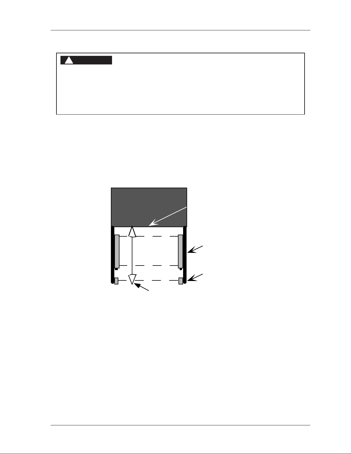
Shadow VI User Manual 1107200
Pass-through Protection
!
DANGER
OPERATOR CAN BE BETWEEN LIGHT CURTAIN AND HAZARDOUS AREA
Ensure that the operator cannot position him- or herself between the light curtain and the
hazardous area. Use another pair of light curtains or a mechanical barrier at knee-to-waist
height to prevent the operator or a passerby from being “trapped” between the light curtain
and the hazard.
Failure to comply with these instructions will result in death or serious injury.
Another important impact on safety distance is “pass-through protection”. To illustrate,
consider that you have determined your safety distance to be 12 inches from the hazardous
point of operation — “pinch point”. There is a danger that a person could become trapped
between the light curtain and the pinch point.
A recommendation would be to install a second set of light curtains at waist height mounted
horizontally between the vertical light curtain and the hazard. See the illustration below.
With Shadow VI, two sets of optic heads can be wired to the same control box.
Press
pinch point
horizontal set
vertical set
safety distance
Figure 2-2. Plan View Illustrating “Pass Through” Protection
The size of the horizontal light curtain should be the minimum length necessary to detect the
thinnest operator standing between the vertical light curtain and pinch point. For example, a
6" light curtain located in the center of a 12" safety distance at waist height may be
reasonable.
Installation and Checkout Chapter 2 page 25
Page 38
1107200 Shadow VI User Manual
Height Considerations
!
DANGER
IMPROPER INSTALLATION
Ensure that the light curtain is installed so it is impossible for anyone to reach over, under, or
around the light curtain and into the hazardous area of the machine without being detected.
Use the correct height light curtain, combined with ancillary physical guards.
Failure to comply with these instructions will result in death or serious injury.
!
DANGER
OPERATOR CAN BE BETWEEN LIGHT CURTAIN AND HAZARDOUS AREA
Ensure that the operator cannot position him- or herself between the light curtain and the
hazardous area. Use another pair of light curtains or a mechanical barrier at knee-to-waist
height to prevent the operator or a passerby from being “trapped” between the light curtain
and the hazard.
Failure to comply with these instructions will result in death or serious injury.
Once you have determined the correct safety distance, you must select the proper curtain
height. Shadow VI comes in sizes ranging from 6" to 60". Shadow must be installed so it is
impossible for anyone to reach over, under, or around the light curtain and into the hazardous
area of the press without being detected. This is accomplished with the proper height light
curtain, combined with ancillary physical guards.
Designing and Mounting Brackets
Once you have calculated the correct safety distance, you can mount your Shadow
transmitter and receiver at this distance from the nearest pinch point (or other hazardous area
of the press). This set of steps lists all the information and dimensions you need to know to
do a good job in designing and mounting brackets. It covers:
1. What requirements you must meet when choosing your mounting location.
2. How to design and mount the brackets so that the Shadow heads can be easily aligned.
3. Maximum openings for side guards used with Shadow light curtains for three-sided
guarding.
4. Mounting Shadow light curtains with mirrors.
5. Mounting Shadow light curtains upside down.
A careful reading of this material will ensure that you will not have trouble mounting and
aligning your Shadow light curtains. After you read this material, design and mount your
brackets.
Universal Mounts
The Shadow VI transmitter and receiver come with universal mounts. These universal
mounts are located at the top and bottom of each head and are held into place by mounting
page 26 Chapter 2 Installation and Checkout
Page 39
Shadow VI User Manual 1107200
screws. They can be rotated ±30° to facilitate installation and alignment. If you need to
pivot a bracket more than 30°, remove the screws, move the bracket 90°, and reattach the
bracket to the head.
Mounting Location Requirements
!
DANGER
IMPROPER INSTALLATION
Ensure that the light curtain is installed so it is impossible for anyone to reach over, under, or
around the light curtain and into the hazardous area of the machine without being detected.
Use the correct height light curtain, combined with ancillary physical guards.
Failure to comply with these instructions will result in death or serious injury.
!
DANGER
OPERATOR CAN BE BETWEEN LIGHT CURTAIN AND HAZARDOUS AREA
Ensure that the operator cannot position him- or herself between the light curtain and the
hazardous area. Use another pair of light curtains or a mechanical barrier at knee-to-waist
height to prevent the operator or a passerby from being “trapped” between the light curtain
and the hazard.
Failure to comply with these instructions will result in death or serious injury.
There are two ways to mount the Shadow universal mounts. You can either mount them
parallel to the light beam. Or mount them perpendicular to the light beam, as might be done
on a gap frame press. When choosing the mounting location, you must make sure the
location meets these requirements:
1. Shadow VI heads must always be installed so that it is impossible for anyone to reach
over, under, or around the light curtain and into the hazardous area of the press without
being detected.
2. The units must be protected from pathways used by forklifts, die carts, and other
material-handling equipment.
3. The mounting location must allow unobstructed access to the point-of-operation.
4. Shadow light curtains must be located at an adequate safety distance from the point of
operation (pinch point) to allow time for the press to stop once the light curtain has been
interrupted. This is explained in the section "Calculating the safety distance" earlier in
this chapter.
5. Every route to the press's pinch point or hazardous area must be guarded. Shadow VI
transmitter and receiver by themselves provide guarding on one side of the press. Mirrors
used with Shadow VI can provide 3-sided protection by "bending" the light curtain
around the hazardous point-of-operation. When Shadow mirrors are not used in
conjunction with the light curtain, however, other guarding means (such as mechanical
side-guards) must be substituted for them, in accordance with OSHA/ANSI guidelines.
Installation and Checkout Chapter 2 page 27
Page 40

1107200 Shadow VI User Manual
How to Design and Mount Brackets or Floor Stands
You mount the light curtains to floor stands or to brackets on your machinery using the
Shadow flanges on the top and bottom of each unit. Wintriss does not supply brackets or
stands with Shadows. You must supply your own.
This section lists the factors you must consider when designing and mounting brackets or
stands. If you need more specific information about designing and mounting brackets for
your particular machinery, do not hesitate to call our technical services department.
If you cannot make your own brackets, we can also give you information on where you can
buy various types of brackets. Brackets must meet these four conditions:
1. They must provide a rigid mounting surface for the Shadow heads. With stands, they
must be rigidly attached to the floor.
2. They must bring the Shadow heads out far enough away from the point of operation to
exceed the calculated safety distance.
3. They must allow the light curtain to be easily aligned.
4. They must allow you to use shock mounts to mount the optic heads. Four shock mounts
are shipped for each head.
It does not matter what type of brackets you design as long as they meet these four
conditions.
The illustrations (Figure 2-3) on the following page show several types of brackets you can
make. It gives you an idea of just some of the types used. See Figure 2-4 and Figure 2-5 for
layout and hole dimensions of the light curtain.
Brackets have to be configured to fit the shape of your particular press. For instance, on some
machinery like straight side presses you can mount angle iron (L-shaped) brackets directly to
a sidewall of the press (see Figure 2-8).
On other machinery, like gap frame presses or bending rolls, you may have to mount the
Shadow light curtains from the bed or platform of the press.
On gap frame presses, do not attach the top Shadow VI bracket to the press frame and the
bottom bracket to the bolster. The upper portion of the press will deflect (pull away) from the
bolster during the work portion of the stroke.
When mounting brackets on the bolster of presses, choose your location carefully. Make sure
the brackets do not prevent dies from being removed from the press. Brackets used must be
made of strong, thick steel so mounting is rigid. These are only a few of the designs you can
make or use. They are shown only to give you an idea of what brackets are. Many different
designs are possible as long as all mounting requirements are met.
page 28 Chapter 2 Installation and Checkout
Page 41
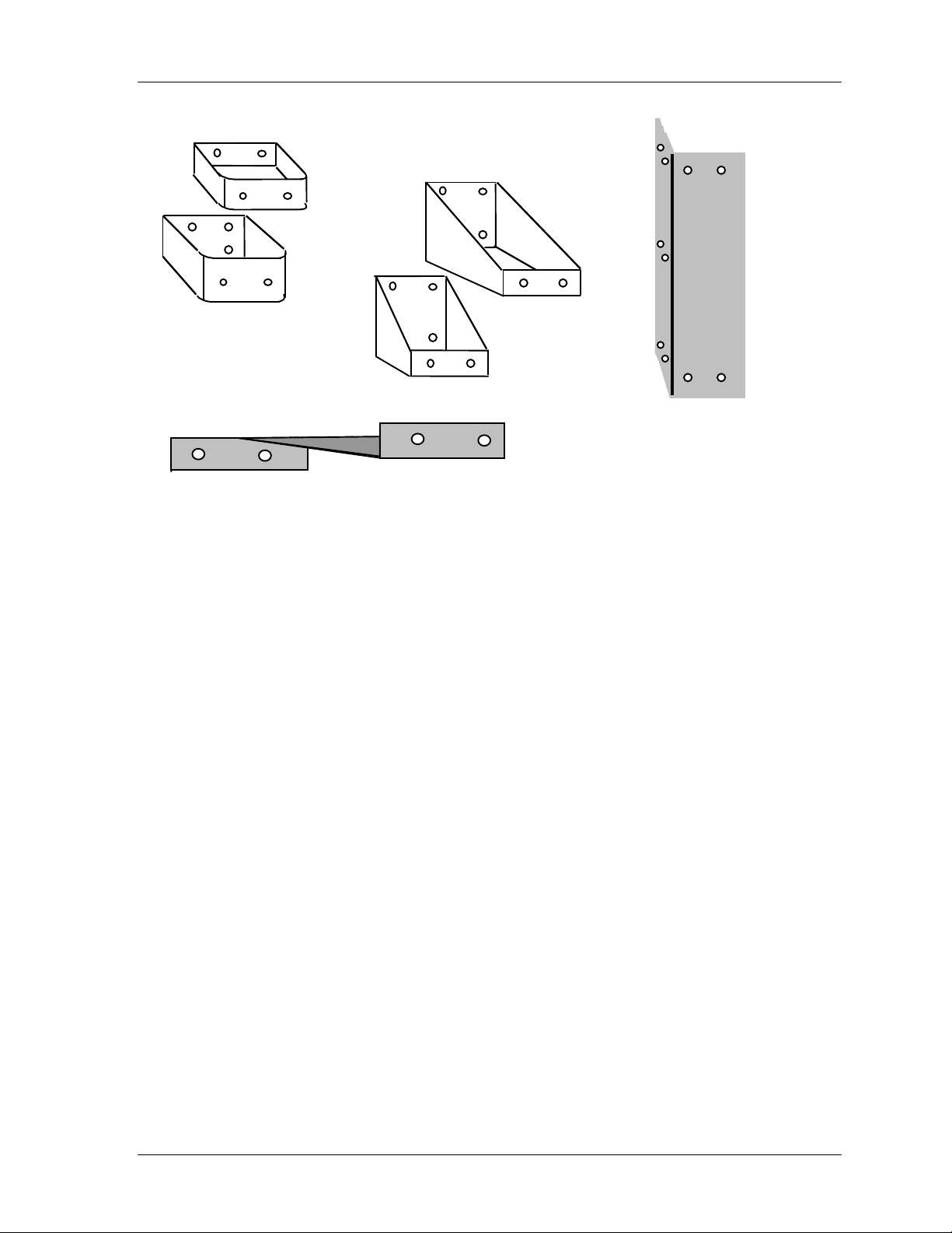
Shadow VI User Manual 1107200
y
p
r
rig
r
gebr
g
r
y
y
pebr
p
p
por
r
rig
y
ed brackets with
ts fo
Box t
L-sha
side su
ackets
Wedge-shaped bracketgood formountin
units to bed orwall of machine
Figure 2-3. Brackets for Shadow Light Curtains
idit
Longangle iron t
acket. Here one unit
b
mounts
la
ht on one
acket.
eof
Installation and Checkout Chapter 2 page 29
Page 42
1107200 Shadow VI User Manual
Table 2-1. Light Curtain Dimensions: inches (cm) * see Figure 2-4
Size A B C
6 (15) 7.75 (19.7) 9.5 (24.1) 11 (27.9)
12 (30) 13.75 (34.9) 15.5 (39.4) 17 (43.2)
18 (45) 19.75 (50.2) 21.5 (54.6) 23 (58.4)
24 (61) 25.75 (65.4) 27.5 (69.9) 29 (73.7)
30 (76) 31.75 (80.6) 33.5 (85.1) 35 (88.9)
36 (91) 37.75 (95.9) 39.5 (100.3) 41 (104.1)
42 (106) 43.75 (111.1) 45.5 (115.6) 47 (119.4)
48 (122) 49.75 (126.4) 51.5 (130.8) 53 (134.6)
60 (152) 61.75 (156.8) 63.5 (161.3) 65 (165.1)
page 30 Chapter 2 Installation and Checkout
Page 43
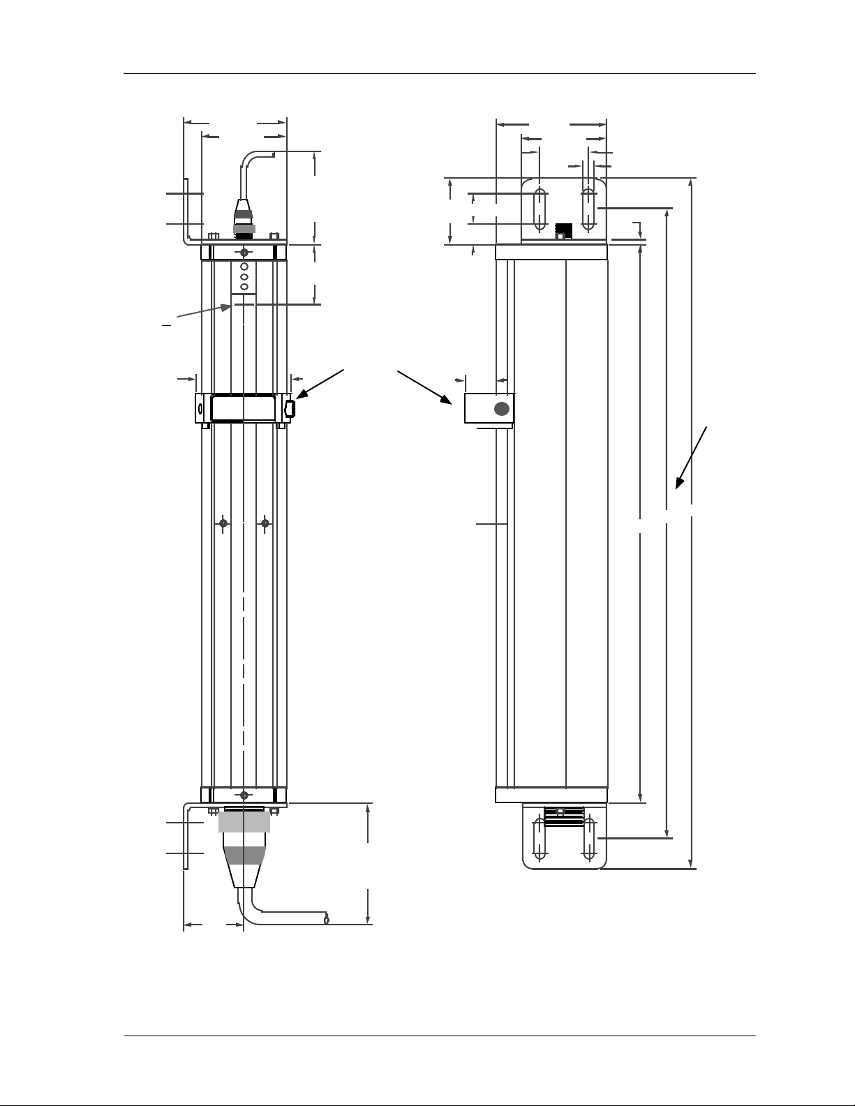
Shadow VI User Manual 1107200
e
location
of
t
1s
beam
2.34
(5.9)
2.55 (6.5)
2.1 (5.3)
2.5 (6.4)
(min. re q'd
blk. wind. cable
allowance)
1.5
(3.8)
blanking
window
1.63
(4.1)
.75 (1.9)
.5 (1.3)
.75
(1.9)
2.75 (7)
2.1 (5.3)
1.2
(3)
.28 (.7)
.12
(.3)
A
see
Tabl
2-1
C
B
3 (7 .6 )
(min. re q'd
heads cable
allowance)
** Use 1/4-20 bolts for mounting
1.5
(3.8)
Figure 2-4. Shadow VI Optic Heads Mounting Dimensions
Installation and Checkout Chapter 2 page 31
Page 44
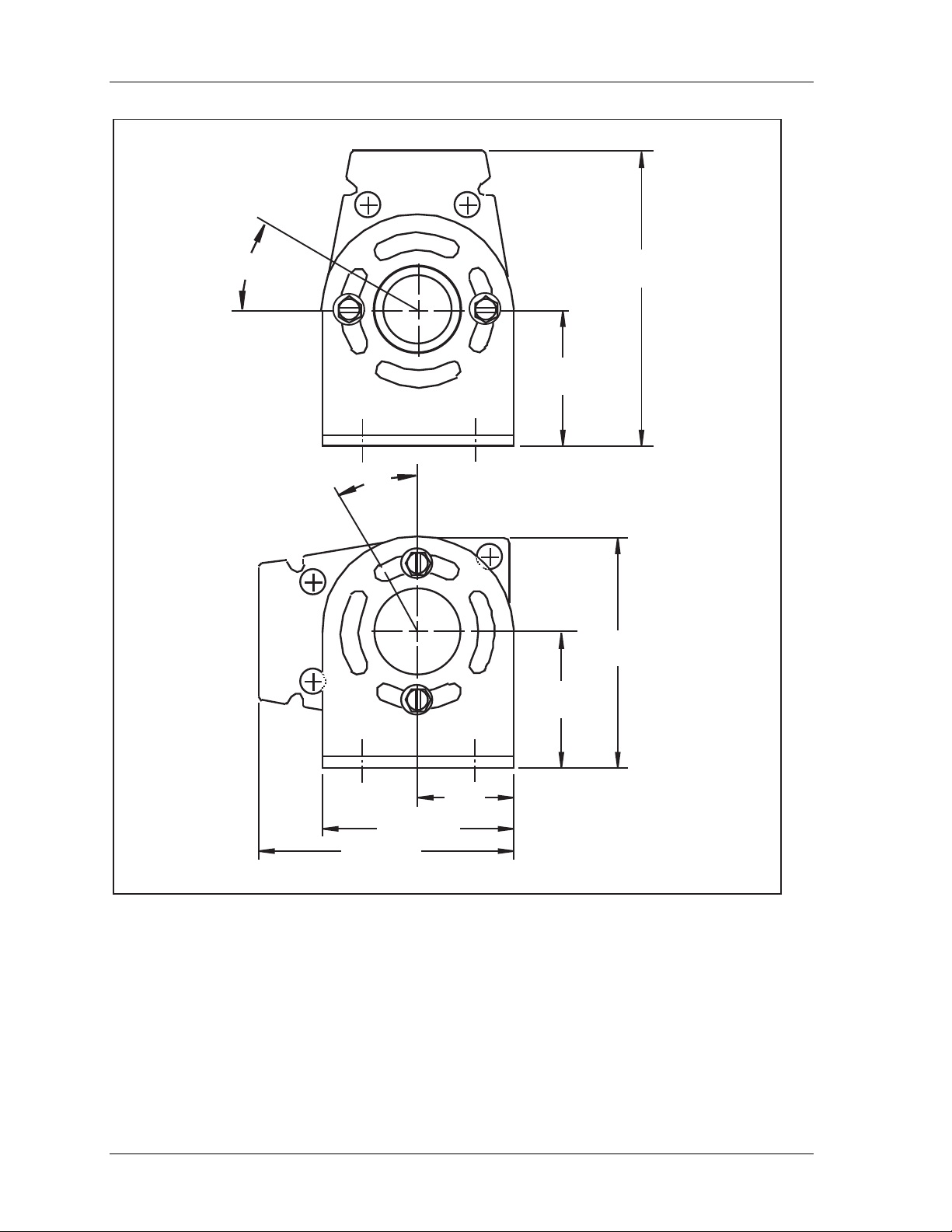
1107200 Shadow VI User Manual
30°
30
3.25
(82,6)
1.5
(38,1)
°
2.55
(64,8)
1.5
(38,1)
1.05
(26,7)
2.10 (53,3)
2.75 (69,9)
Dimensions:
inches
(mm)
Figure 2-5. Top Views of Shadow VI Optic Heads (Universal Mounts)
page 32 Chapter 2 Installation and Checkout
Page 45

Shadow VI User Manual 1107200
Shadow optic heads must be attached at both ends so that vibration does not cause the units
to go out of alignment. It is all right to mount Shadow VI brackets to your press at one end
only (to the bolster of a press, for instance). However, the bracket must be designed so that
the shock mounts supplied with your heads can be placed between the head and the bracket.
You can mount your Shadows directly to a vertical wall or column of your press if the
location meets all mounting requirements, including safety distance.
Installing Brackets with Alignment in Mind
The bracket design must allow adjustment of the Shadow VI heads once they are mounted.
Shadow light curtains may have to be moved slightly up or down or rocked slightly to one
side or the other to align them once they are mounted (you will see why when we discuss
alignment).
As we mentioned earlier the Shadow universal mounts allow subtle adjustments of the heads.
These mounts can be rotated ±30° to facilitate installation and alignment. If you need to
pivot a bracket more than 30°, remove the mounting screws, move the bracket 90°, and
reattach the bracket to the head.
Alignment Considerations
Although Shadow is easy to align and tolerant of vibration and shock, optic life is improved
by alignment optimization.
Optimum alignment can easily be accomplished using the optional Laser Alignment Tool
(see "Using the Laser Alignment Tool" later in this section), which slides along the groove
on either optic head.
As long as the phototransistor's field is anywhere within the funnel-shaped path of the light
beam, Shadow will align. The optic heads don't have to be perfectly aimed (see Figure 2-6).
What alignment means
The alignment procedure is explained in the section "Aligning and tightening down Shadow
VI components". For Shadows to operate properly, each infrared LED emitted horizontally
from the Shadow transmitter must be detected by each PT in the receiver.
The PTs as well as the LEDs are located on the front of each unit. You cannot see them but
their location can be determined using the alignment indicator guides on the Shadow
receiver. To find the mating beam on the transmitter, use the same measurement from the
base of the receiver to the lowest indicator guide. Each LED must match up with its opposite
phototransistor when the Shadow light curtains are mounted as shown in the next illustration.
Therefore, Shadow optic heads must be mounted in the same plane.
You should always try to mount the brackets as precisely as possible. Then, the alignment
procedure in the section "Aligning and tightening down Shadow VI components" will be
easy. Also note that the optic heads don't have to be mounted vertically (although this is
certainly a common approach). They can be mounted at any angle as long as they are in the
same plane.
Installation and Checkout Chapter 2 page 33
Page 46
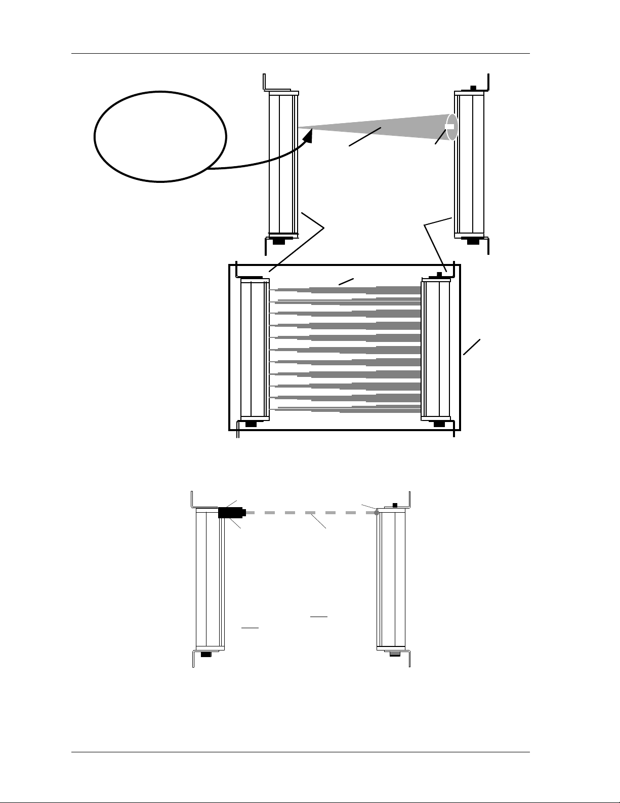
1107200 Shadow VI User Manual
If PT is in funnel-shaped
light path, Shadow is in
alignment, even if optic
heads are not
perfectly aligned.
funnel-
shaped
light path
phototransistor
(PT)
transmitter
light beams
receiver
Figure 2-6. Transmitter and Receiver Properly Aligned
transmitter
receiver
plane of
alignment
Laser
Alignment
Tool
Laser Alignment Tool is used
to achieve optimum alignment.
Installing it at the very
very
bottom of optic head will
not block any beams.
laser's
alignment path
top and
Figure 2-7. Using Laser Alignment Tool to Properly Align Shadow
page 34 Chapter 2 Installation and Checkout
Page 47
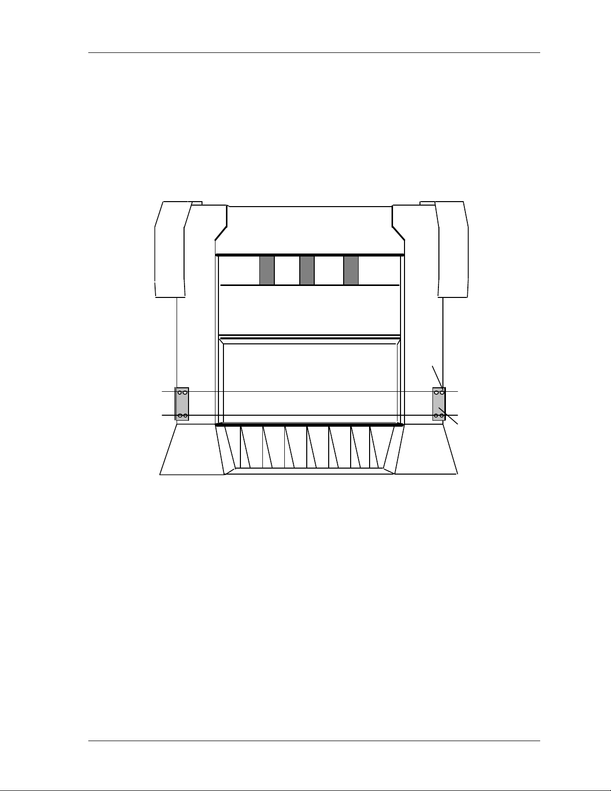
Shadow VI User Manual 1107200
Aligning brackets
When mounting your brackets you can draw a leveling line using the center of the bracket
holes as the end points (see the next illustration). When you mount the Shadow VI flanges
onto the bracket holes, the Shadow light curtains will be aligned (or at least very close).
Use a plumb or leveling line and square to properly align the brackets. Use the bed of your
press (if applicable) or the floor as a leveling reference point. Make sure that the brackets are
placed in the same plane.
top mounting
holes
levelling lines through
center of bracket holes
bracket
Figure 2-8. Aligning Brackets Using Mounting Holes So Shadow Light Beams
Line Up Later When Mounted
Maximum Openings for Side Guards
When mechanical side guards are used in addition to the Shadow light curtains for three
sided-guarding, you must ensure that the openings between or around the guards meet
OSHA requirements. You must also make sure that the openings in the guard material itself
(wire, extruded mesh, rods, etc.) or openings between the guards and working surface meet
OSHA requirements.
OSHA requirements for the maximum openings allowed in guards or between the guards and
the top and bottom of the working surface are listed in OSHA Table 0-10. See Table 2–2.
Installation and Checkout Chapter 2 page 35
Page 48
1107200 Shadow VI User Manual
Table 2-2. OSHA Table 0-10
Distance of opening
from pinch point
1/2" to 1 1/2" 1/4"
1 1/2" to 2 1/2" 3/8"
2 1/2" to 3 1/2" 1/2"
3 1/2" to 5 1/2" 5/8"
5 1/2" to 6 1/2" 3/4"
6 1/2 to 7 1/2" 7/8"
7 1/2" to 12 1/2" 1 1/4"
12 1/2" to 15 1/2" 1 1/2"
15 1/2" to 17 1/2" 1 7/8"
17 1/2" to 31 1/2" 2 1/8"
Using Mirrors with Shadows
Maximum Dimension
of Opening
NOTICE
MIRRORS DECREASE SCANNING DISTANCE AND ANGLE OF DIVERGENCE
• Allow for a reduction in scanning range of 10% for each mirror you use. For example, if your
extended range unit normally scans 50’ and you use two mirrors, it will now scan 40’ (50’
minus 10’).
• Allow for a reduction in angle of divergence if you use mirrors. This greatly reduces the light
curtain’s tolerance of vibration and makes alignment more critical.
You can use mirrors with Shadow VI for two- or three-sided guarding. Wintriss offers frontreflective mirrors that provide optimal light transmission or reflection. Mirrors can be
optionally purchased from Wintriss. Dimensions for mirrors are shown in Figure 2-9.
Wintriss does not recommend the use of other mirrors or other reflective surfaces as they
may severely reduce vibration tolerance or scanning distance. The Shadow transmitter and
receiver are aimed at the mirrors. The light beam is reflected from the transmitter to the
receiver by way of the mirrors. This method could be used on any type of machinery where
three-sided guarding is needed. When using mirrors, your setup will look similar to the
drawing in Figure 2-10. You do not have to arrange the Shadow light curtains and mirrors in
a rectangle as shown, however.
You can adjust the mirrors to reflect light from the Shadow VI transmitter at other angles
besides right angles. Shadow VI aligns in the same way using mirrors as without them. Even
though the transmitter and receiver will not be pointed at each other, the units and the mirrors
page 36 Chapter 2 Installation and Checkout
Page 49
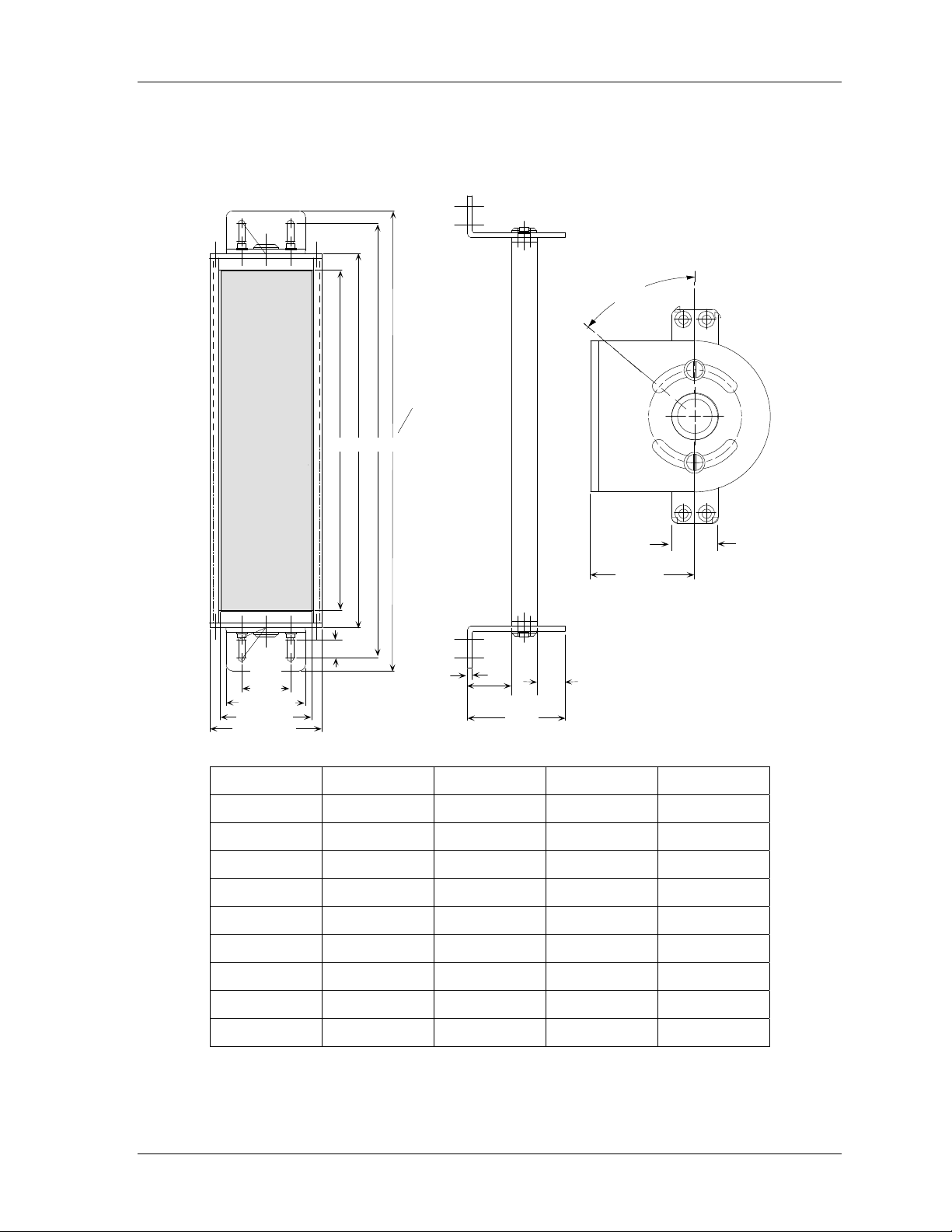
Shadow VI User Manual 1107200
must be mounted in line with each other so each phototransistor in the receiver can detect the
light beam coming from its opposite light emitter. The Laser Alignment Tool (illustrated in
Figure 2-6 and Figure 2-7) is a useful tool when installing mirrors.
Top view
50°
MAX
See table
A B C D
1
2.25
(5.72)
.75 (1.91)
2
(5.08)
3.25 (8.26)
3.75 (9.53)
4.62 (11.73)
.19
(.48)
1.75
(4.45)
3.89
(9.88)
1
(2.54)
(2.54)
Model A B C D
6” 8 9.38 11.88 12.64
12” 14 15.38 17.88 18.64
18” 20 21.38 23.88 24.64
24” 26 27.38 29.88 30.64
30” 32 33.38 35.88 36.64
36” 38 39.38 41.88 42.64
42” 44 45.38 47.88 48.64
48” 50 51.38 53.88 54.64
60” 62 63.38 65.88 66.64
Figure 2-9. Shadow VI Mirror Dimensions
Installation and Checkout Chapter 2 page 37
Page 50
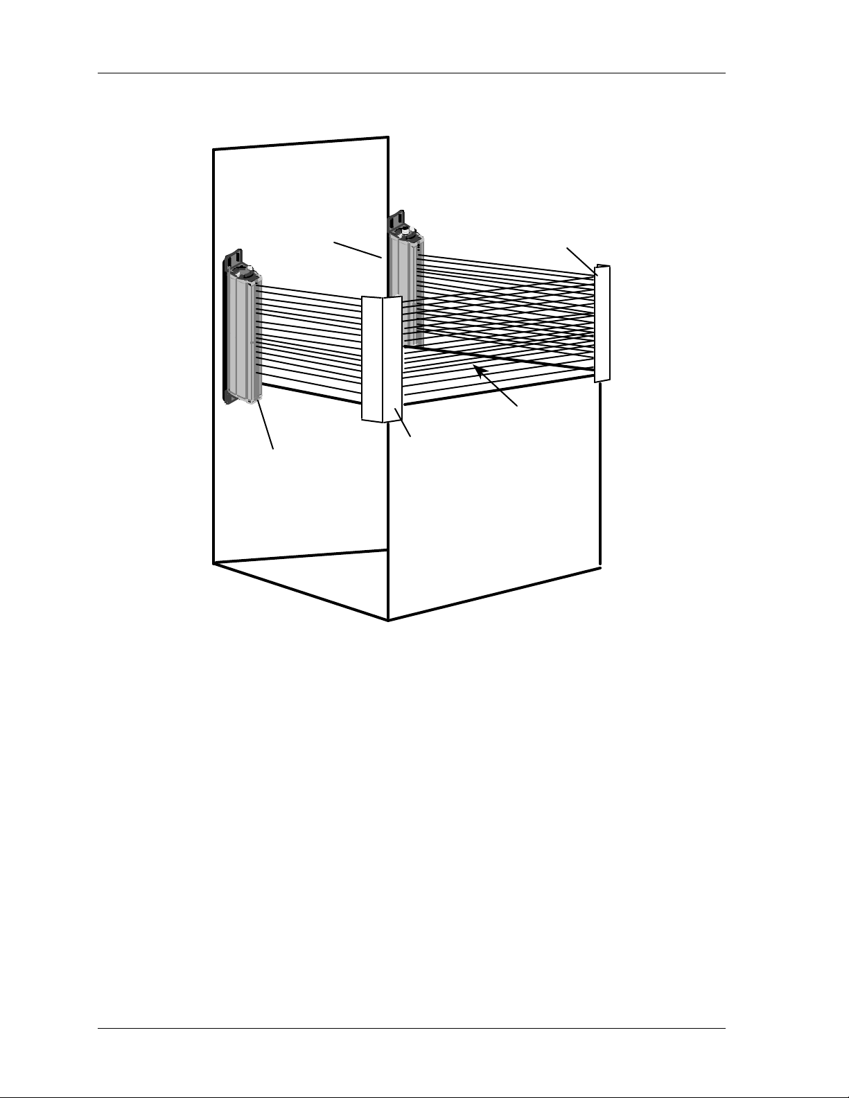
1107200 Shadow VI User Manual
corner
receiver
mirror
light beams
transmitter
corner
mirror
Figure 2-10. Representation of Shadow with Mirrors for Three-sided Guarding
Use of Laser Alignment Tool Is Useful During Mirror Installation
page 38 Chapter 2 Installation and Checkout
Page 51

Shadow VI User Manual 1107200
Using Weld Shields
The operation of Shadow VI is not affected by smoke, dirt, or oil found in a typical industrial
environment. In a more severe environment, you may need to install clear plastic shields that
provide protection from weld splatter and other hazards.
Weld shields are clear plastic covers that fit on the face of the transmitter and/or receiver.
They come in kits ready for installation and can be easily replaced if they become so
damaged or scratched that the light curtain no longer indicates “green” during normal
operation. (see the Troubleshooting Guide in Chapter 4 of this manual).
If you want to install a weld shield, you must order a separate kit (weld shield #42873xx,
where “xx” is the height of the optic head in inches) for each optic head. Detailed
instructions for installation are included in each kit, along with the necessary screw and
clip(s). Each optic head has a screw hole for mounting a shield.
Mounting Shadow Light Curtains Upside Down
There is nothing inherent in the design of Shadow VI heads that prevents them from being
mounted upside down. If you are mounting Shadow VI this way for any reason, both heads
must be inverted. Shadow heads can also be mounted at any angle as long as they are in the
same plane. Vertical mounting is the easiest.
Avoiding Cross Talk When Mounting 2 Sets of Shadows
Because the receiver only accepts infrared light pulses of a certain duration in proper
sequence, Shadow cannot be affected or fooled by other light sources. All other continuous
light sources and even pulsed light sources are "tuned out", and Shadow continues to work.
Also, changes in area lighting or even flashing strobe lights will not affect operation. Even if
the Shadow receiver were flooded with infrared light of the same intensity, the receiver
would not be fooled because it only accepts light pulses of the right frequency in proper
sequence. Instead it would send a stop command to the press.
In some cases, however, using two sets of Shadows in close proximity of each other may
cause "cross talk". Cross talk occurs when the LEDs from the first set's transmitter are
detected by the phototransistors from the second set's receiver.
If your application requires that you mount a set of Shadows horizontally next to a vertical
set to detect an operator between the vertical set and the pinch point, you may need to
alternate these sets to avoid any incidence of cross talk between sets. To do this, you may
need to mount the horizontal transmitter next to the vertical receiver and vice versa.
Another scenario where cross talk may occur involves machines that are close together. Use
caution if the guarded machines are too close together, such that the light from one
transmitter may be detected by the other press's receiver.
To avoid any incidence of cross talking, you can select from several solutions. One is to
insert a barrier of some type, such as a blind, between the two sets of Shadow heads. Make
sure that the barrier runs all the way from the transmitter to the receiver. A second approach
is to reverse the position of the transmitter and receiver on the second press. Another option
is a combination of the above. The next illustration shows reversing the position of the optic
heads on the second press.
Installation and Checkout Chapter 2 page 39
Page 52
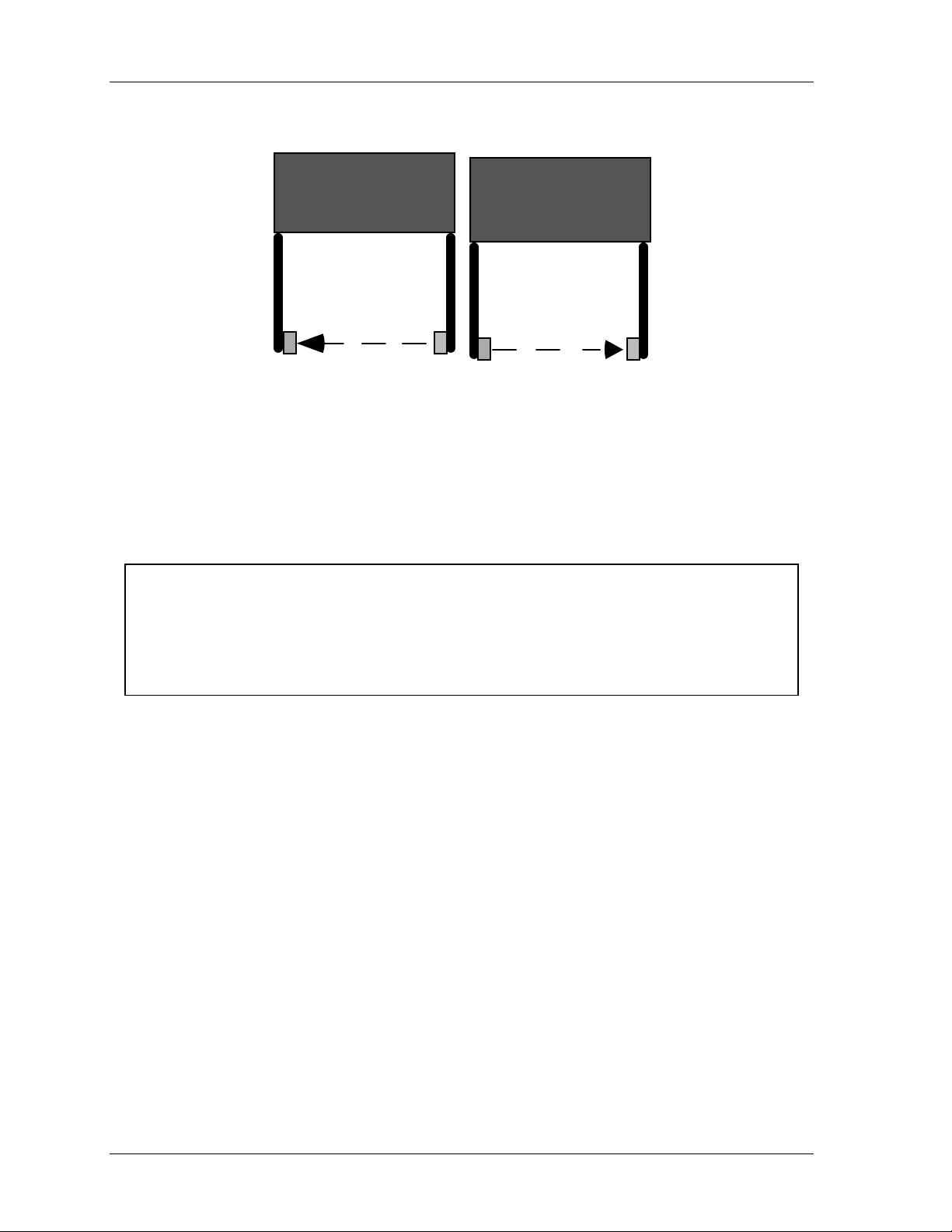
1107200 Shadow VI User Manual
Press #1
TXRX
Press #2
TX
RX
Figure 2-11. One Way to Avoid Cross Talk - Reversing Transmitters (TX) and
Receivers (RX)
Loosely Mounting Shadow VI Transmitter and Receiver
CAUTION
FAULTY SHOCK MOUNT INSTALLATION
Install the shock mounts between the mounting surface and the universal mounting brackets
that hold the optic heads in order to protect the heads from damage.
Failure to comply with these instructions could result in property damage.
Leave the Shadow VI heads loose on their mounting brackets so that you can properly
determine wiring length and conduit required. You will align and tighten the heads later.
Shock mounts are provided to help protect the optic heads of your Shadow VI from damage
due to shock or vibration.
Follow the steps below to loosely mount the optic heads (transmitter and receiver).
1. Locate four mounting holes for each head, in either your brackets or on a solid surface as
described above. The shock mount studs have 1/4-20 threads. For installation into a
solid surface, use a No. 7 drill and 1/4-20 tap. For through-installation onto a metal
bracket, drill clearance holes.
2. Before mounting the optic heads, install four shock mounts for each head. Thread a
shock mount into each of the four tapped holes in the mounting surface (Figure 2-12,
next page), or use a lock washer and nut to secure each shock mount to a metal bracket.
3. Using lock washers and nuts, loosely mount the optic heads onto the shock mounts, as
indicated in Figure 1.
4. Follow the instructions below to complete the installation. You will align and adjust the
heads (page 61) after you mount and wire the control.
page 40 Chapter 2 Installation and Checkout
Page 53
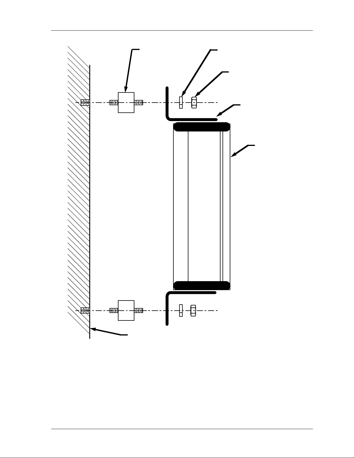
Shadow VI User Manual 1107200
Shock mount
(4 places)
Lock washer
(4 places)
Nut
(4 places)
Universal
mounting bracket
Optic head
(transmitter
or receiver)
Mounting surface
Figure 2-12. Mounting an Optic Head with Shock Mounts
Installation and Checkout Chapter 2 page 41
Page 54
1107200 Shadow VI User Manual
Mounting the Control
DANGER
!
CONTROL AFFECTS LIGHT CURTAIN OPERATION
Install the light curtain control in a location where access to it will not affect the operation of
the light curtain.
Failure to comply with these instructions will result in death or serious injury.
DANGER
!
CONTROL INSIDE THE GUARDED AREA FOR PERIMETER GUARDING
Install the light curtain control outside the guarded area for perimeter guarding applications.
Failure to comply with these instructions will result in death or serious injury.
1. Determine an appropriate location to mount the control. It should be mounted in an area
where personnel can easily see the warning indicators and also have access to the
circuitry, without interfering with the operation of the light curtains. The control must
never be installed inside the protected area in perimeter guarding applications. The
enclosure can be mounted to the press, on a free-standing pedestal, on a pendant, or at the
entrance of a location used for area guarding.
2. Drill four holes for mounting, and tap, if necessary. Shock mount studs are 1/4-20.
Mount the enclosure using the enclosed shock mounts and mounting flanges. Use a No.
7 drill and 1/4-20 tap. Refer to Figure 2-13 for mounting dimensions.
Connecting RF (Radio Frequency) Ground
To reduce electromagnetic interference, connect the RF ground terminal on the top of the
control enclosure (Figure 2-13) to a clean ground using a low-impedance ground strap. If
your installation does not experience electromagnetic interference, you may not need to use
this additional grounding.
NOTICE
A clean ground is a connection to the earth separate from the electrical service (green wire)
ground.
A low-impedance ground strap is made from braid at least 1/2” (1.25 cm) wide.
page 42 Chapter 2 Installation and Checkout
Page 55
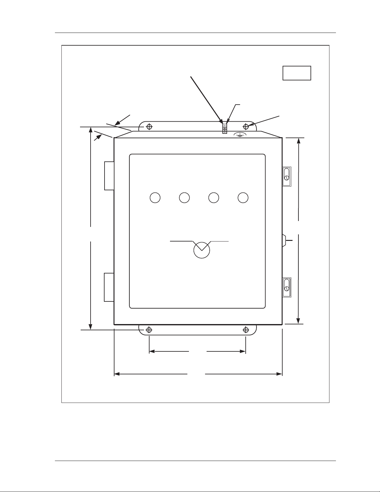
Shadow VI User Manual 1107200
Connect this terminal to a clean ground
using a low impedance ground strap.
See “Connecting to RF ground.”
3.50
(8.89)
9.75
(24.76)
CURTAIN
CLEAR
FLOATING
WINDOW
OPERATE
STOP
SIGNAL
RESET
8-32 thread
RESET
REQUIRED
inches
(cm)
0.31
(0.79)
4 places
9.00
(22.86)
LIGHT CURTAIN
5.00
(12.7)
typical, 2 places
7.00
(17.78)
Figure 2-13. Shadow VI Control Enclosure Mounting Dimensions
Installation and Checkout Chapter 2 page 43
Page 56
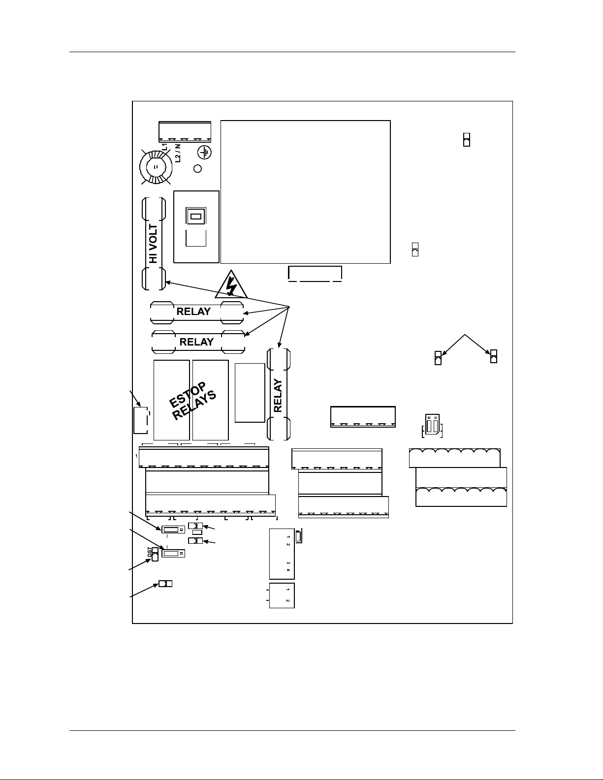
1107200 Shadow VI User Manual
KEYLOCK
SWITCH
CONNECTOR
POWER TB1
1
TB1
F1
F2
F3
K1 K2
J13
S2
115 V
VOLTAGE
SWITCH
K3
STATUS
RELAY
CAUTION
POWER
TRANSFORMER
DISPLAY
CONNECTOR
FUSES
F4
TB5
J11
SS INDICATOR
OUTPUTS
GRN AMB RED YEL V-OUT
1
OPTIC HEADS
POWER LED
DS3
OBSTRUCTION
DS1
1 SET/2 SETS
JUMPERS
J12
OPTIC HEADS
POWER LED
DS4
LEDS
DS2
MPCE2
JUMPER
MPCE1
JUMPER
RESET ON
LED
TRANSMITTER
ACTIVE
LED
FSD1 FSD2 STAT
UPPER 1-10
TB4
STOP CIRCUITS
LOWER 11 - 20
MPCE1 MPCE2 RESET XMTR IN T
DS6
MPCE2 LED
J15
INT
DS8
J14
MPCE1 LED
DS5
GND
RESET ON
INTERRUPT
FLOATING
WINDOW
STAT=GRN
VCR VCC GNDSHUTDOWNSYNCSHIELD
TB3
1
TRANSMITTER 1
UPPER 1 - 10 (#1)
TRANSMITTER
LOWER 11 - 20 (#2)
VCR VCC GND SHUTDOWN SYNC SHIELD
ON OFF
OPTIONS
S4
S1
PWR UP
TRANSMITTER 2
RESET
DISABLE
TB2
1 SET
FWIN VCC GND 1A SYNC SHIELD1B
UPPER 1 - 10 (#1)
1
RECEIVER
LOWER 11 - 20 (#2)
FWIN VCC GND 2A SYNC SHIELD2B
RECEIVER 2
Figure 2-14. Location of Components, Shadow VI Control
(Important components shown and labeled)
RECEIVER 1
page 44 Chapter 2 Installation and Checkout
Page 57
Shadow VI User Manual 1107200
Wiring the Transmitter and Receiver to the Control
!
DANGER
FULL REVOLUTION MECHANICAL POWER PRESSES AND OTHER MACHINES
CANNOT BE STOPPED IN MID-STROKE OR MID-CYCLE
• DO NOT use Shadow safety light curtains on full-revolution clutched machinery or other
equipment that cannot be stopped at any point in its stroke or cycle.
• Use Shadow safety light curtains only on machinery that can be stopped at any point in its
stroke or cycle.
Failure to comply with these instructions will result in death or serious injury.
!
DANGER
PRESS MAY CONTINUE TO MOVE AFTER INTRUSION
• Ensure that Shadow is wired to the emergency stop circuitry of the press.
• Ensure that any stop initiated by the light curtain is an immediate stop, one that occurs
immediately after the stop signal is sent to the machinery. (If the light curtain is wired by
mistake to the top-stop circuitry, the press continues its stroke until it reaches the top of the
stroke, even after an intrusion or obstruction is detected.)
Failure to comply with these instructions will result in death or serious injury.
!
DANGER
STOP CIRCUITS NON-OPERATIVE IN SOME MODES
Wire the light curtain to your press control circuit so the stop signal from the light curtain
stops the machine immediately in all modes of operation, including inch.
Failure to comply with these instructions will result in death or serious injury.
!
WARNING
ELECTRIC SHOCK HAZARD
• Ensure that the power source is off before you make any wiring connections.
• Disconnect power from the machinery it is connected to before making any wiring
connections. This includes disconnecting power to the machine control and motor.
• Ensure that all procedures are performed by qualified personnel.
Failure to comply with these instructions could result in death or serious injury.
NOTICE
LOCKOUT MAY NOT BE REQUIRED
If light curtains are installed so they are active in all press operating modes, it may not be
necessary to lock out the press during routine die changes. Refer to the relevant safety
standards for more details.
Installation and Checkout Chapter 2 page 45
Page 58
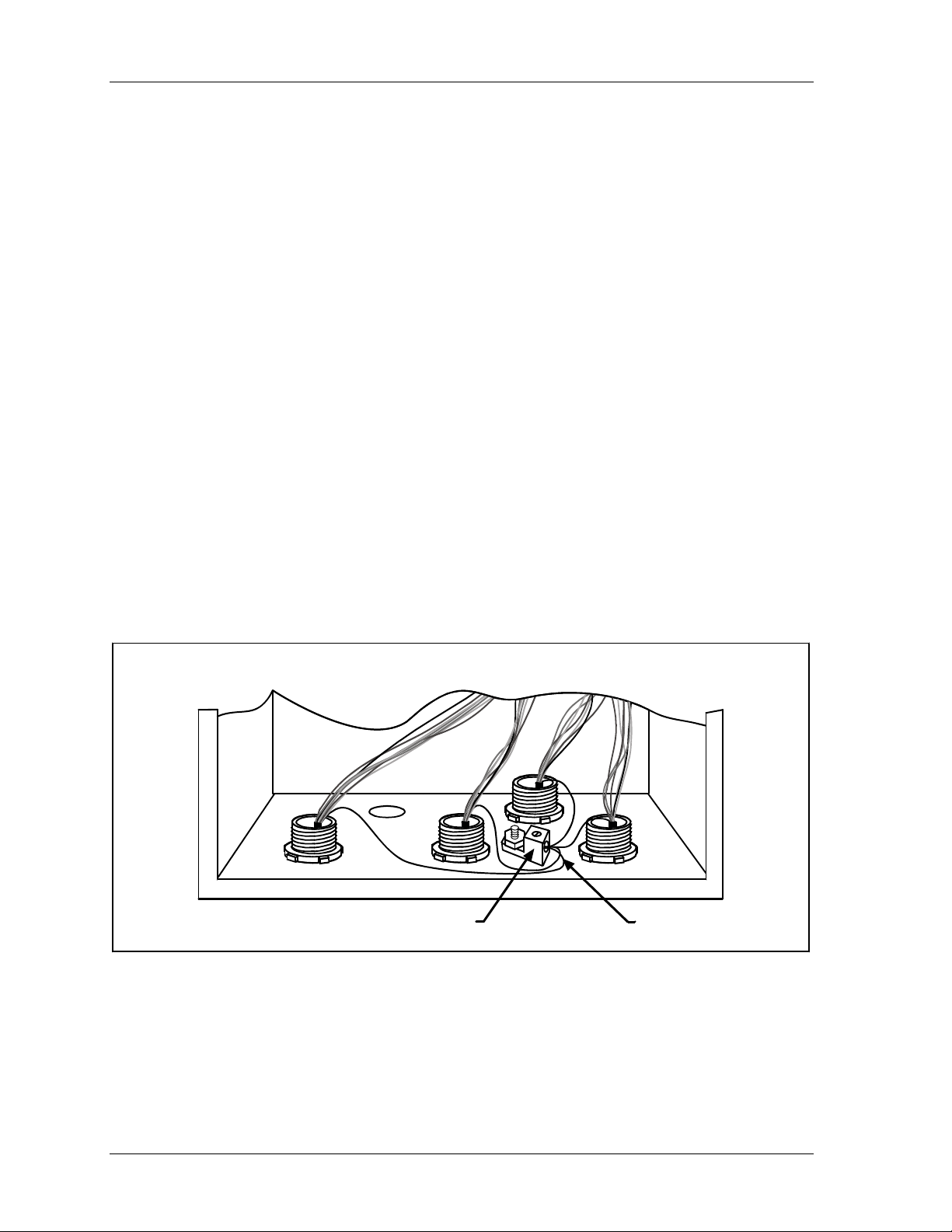
1107200 Shadow VI User Manual
The instructions below describe how to wire the Shadow transmitter and receiver to the
control.
Terminating Shields of the Head Cables, next section
Connecting the Head Cables to the Control, page 47
If You Have a Second Set of Shadow Optic Heads, page 49
Terminating Shields of the Head Cables
The shields of the head cables must be terminated close to their entry into the control box.
Follow the instructions in this document for terminating these cable shields.
Follow the steps below to terminate the shields of the cables that connect to your light curtain
heads. Refer to the figure above, the tables on the next page and the figure at the end of this
document.
1. Strip the cable jackets back as far as the end of the conduit fittings.
2. Cut the drain wires to a length that they can reach and be inserted into the set screw
terminal.
3. Loosen the set screw in the set screw terminal. Twist together the ends of the drain wires
and insert in the hole in the set screw terminal under the end of the set screw.
4. Tighten the set screw and check that all drain wires are firmly connected.
5. Connect the rest of the wires in the cables to the terminal blocks as instructed in the next
section.
Set screw terminal Drain wires
Figure 2-15. Terminating Drain Wires to Set Screw Terminal
Showing Connection for Two Pairs of Heads
page 46 Chapter 2 Installation and Checkout
Page 59

Shadow VI User Manual 1107200
Connecting the Head Cables to the Control
NOTICE
Terminate the shields of the head cables as instructed in the previous section.
1. Find the two interchangeable quick connect cables, and plug them into the bottom of the
transmitter and receiver. The connection is keyed. Twist the locknut so the connection is
tight.
2. Run the cables through separate 1/2" flexible, liquid-tight conduits from the Shadow VI
transmitter and receiver to the knockouts at the bottom of the control (receiver should go
into right front knockout and transmitter into the center). Because the control enclosure
is rated NEMA 2/IP52, you must use conduit of the same rating and make proper
connections to ensure suitable protection with the enclosure.
NOTICE
If you have a second set of Shadow heads, wire them through the remaining knockouts.
3. Next you need to properly terminate the conduits at the transmitter and receiver. You can
use either of these approaches or one of your own. In either case, you must supply your
own parts.
a. Use cord grips to secure the cables in the liquid-tight conduits and 1/2" hose clamps
to support the conduits in place close to the transmitter and receiver.
b. Use 2 junction boxes located near the transmitter and receiver to secure the cables
and the liquid-tight conduits.
4. Open the control by loosening the locking screw. Terminate the cable shield for each
cable as described in the next section.
5. Locate terminal blocks TB2 and TB3. Refer to the location of components pictured in
Figure 2-14 earlier in this chapter. Notice that there are actually two connectors at TB2
and two at TB3. If you have only one set of Shadow heads, the receiver will be wired
into the upper level TB2 connector, and the transmitter into the upper level TB3
connector. If you have a second set, they are wired into the lower levels of TB2 (receiver
2) and TB3 (transmitter 2).
NOTICE
LABEL CABLES CAREFULLY
Carefully label the transmitter and receiver cables inside the control. This will help
troubleshoot the light curtains after installation, if necessary.
If you connect two sets of heads, be sure to separately label the cables for set #1 and set
#2.
5. Measure the wires to fit and cut the wires as necessary.
6. Start by wiring the receiver. Remove the L-shaped connector from TB2 (upper level).
Attach the wires to this connector as shown in Table 2-3 at the end of this section. You
can also refer to Figure 1 at the end of this manual.
Installation and Checkout Chapter 2 page 47
Page 60

1107200 Shadow VI User Manual
To connect a wire, find the correct terminal and loosen the screw over it by turning it
counterclockwise. Strip the correct wire for this terminal 1/4" (6.4 mm) from end. Insert
bare wire into the terminal 90% of the way. Tighten the screw. The metal tooth inside the
terminal will clamp down on the bare wire for a tight connection. Make sure that the
metal tooth is clamped down on the bare part of the wire, not on the insulation.
7. Once you have completed the wiring for the receiver, plug the L-shaped connector firmly
back into its base. It only can go in one way.
8. Now wire the transmitter. Remove the L-shaped connector from TB3 (upper level).
Attach the wires to this connector as shown in Table 2-4 at the end of this section. You
can also refer to Figure 1 at the end of this manual.
9. Once you have completed the wiring, plug the L-shaped connector firmly back into its
base. It only can go in one way.
10. Make sure you have properly connected all wires and have double checked all
connections when done.
Table 2-3. Connecting Light Curtain Receiver Head to TB2 in Controller
Set #1 Heads to Upper Level; Set #2 Heads to Lower Level
RCVR TB2 Wire color Terminal signal
Pin #1 orange FWIN
Pin #2 red VCC
Pin #3
Pin #4 brown 1B
Pin #5 green 1A
Pin #6 yellow SYNC
Terminate shield to set screw terminal near entry point.
(See “
Terminating Shields of the Head Cables,” page 46.)
blue
and
black
GND
page 48 Chapter 2 Installation and Checkout
Page 61
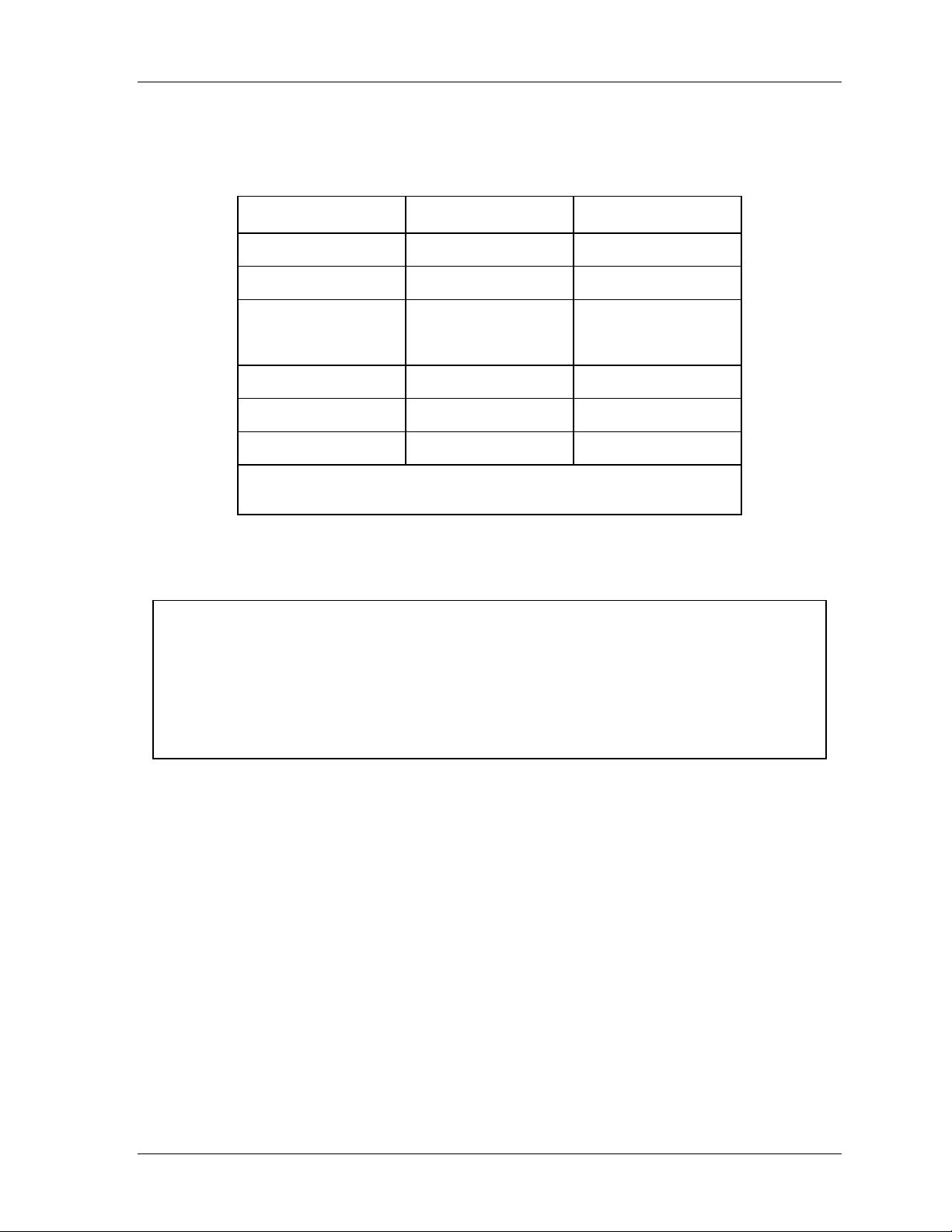
Shadow VI User Manual 1107200
Table 2-4. Connecting Light Curtain Receiver Head to TB3 in Controller
Set #1 Heads to Upper Level; Set #2 Heads to Lower Level
XMTR TB3 Wire color Terminal signal
Pin #1 orange VCR
Pin #2 red VCC
Pin #3
blue
and
GND
black
Pin #4 brown SHTD
Pin #5 green SHTD
Pin #6 yellow SYNC
Terminate shield to set screw terminal near entry point.
(See “Terminating Shields of the Head Cables,” page 46.)
If You Have a Second Set of Shadow Optic Heads
NOTICE
W HEN USING TWO SETS OF HEADS
• Carefully label the transmitter and receiver cables for set #1 and set #2. This will help with
troubleshooting your Shadow installation, if necessary.
• Run the cables for set #2 in a separate conduit from set #1’s cables.
• Set Jumper J12 to “2 SETS.” See page 61.
If you have a second set of optic heads, follow the steps in the previous section to connect
the head cables of the second set of heads to the lower level of TB2 (receiver 2) and TB3
(transmitter 2) in the control. Run the cables in separate conduits. Refer to Tables 2-3 (for
receiver) and 2-4 (for transmitter).
Set Jumper J12 to “2 SETS.” This enables operation of the second set of heads. See page 61.
Installation and Checkout Chapter 2 page 49
Page 62
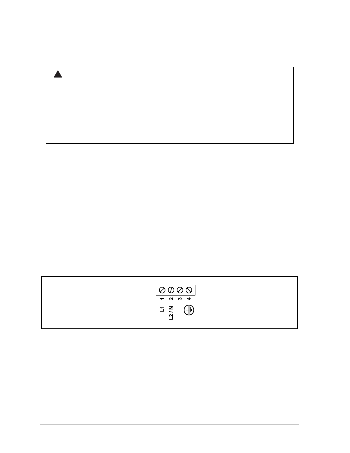
1107200 Shadow VI User Manual
Connecting AC Wiring to the Control
!
WARNING
ELECTRIC SHOCK HAZARD
• Ensure that the power source is off before you make any wiring connections.
• Disconnect power from the machinery it is connected to before making any wiring
connections. This includes disconnecting power to the machine control and motor.
• Ensure that all procedures are performed by qualified personnel.
• Complete all installation procedures before connecting wires to the AC power source.
Failure to comply with these instructions could result in death or serious injury.
Wiring is a straightforward and simple procedure. The control is wired to a 115 VAC 50-60
Hz single phase power source. (Note: Shadow VI can also be used with 230 VAC, 50 Hz.
Step 4 below explains how to switch to 230 VAC.)
Follow these wiring guidelines:
• All wires can be run through a flexible liquid-tight conduit to the control as long as
all circuits are the same voltage. If your emergency stop circuits are low voltage
circuits (such as 24V), run two conduits— for instance, one for 115V wires and one
for 24V wires.
• Bring the wiring connections for AC power to a convenient point so that you can tie
them to the appropriate connector. No. 16 wire is recommended for these circuits
(No. 14, if local codes require it).
Follow the steps below to connect AC wiring to your control.
1. Open the control. Near the top left of the control board, you will see the connector for
AC power (terminal block TB1) and the power supply (to the right of TB1).
TB1
Figure 2-16. Terminal Block TB1 Connections
2. Determine how you will bring wiring from your 115 VAC power source (or 230V source
if applicable) to the knockout hole at the top of the unit. These wires should be connected
directly to the press control transformer. For 115 VAC, you need three wires—high (red),
neutral (white) and ground (green).
page 50 Chapter 2 Installation and Checkout
Page 63
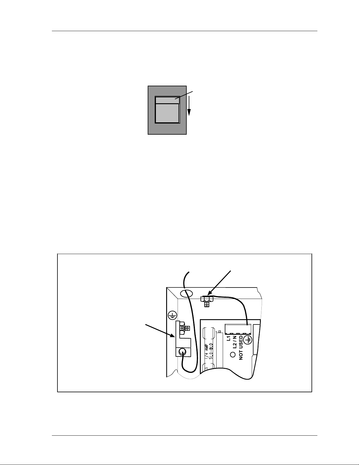
Shadow VI User Manual 1107200
3. Locate the 115V-230V voltage selector switch (S2) on the control board. It is located
just below TB1. If your AC power is 115V, check to see that "115V" is displayed in the
switch cavity. If your AC power is 230V, push the handle down.
Handle.
Push
115V
down
for 230V
Figure 2-17. Setting Voltage Selector Switch S2
4. Run the power wires to the control enclosure. If your stop circuits are 115V, the AC
wiring and stop circuits will enter the enclosure through the same flexible, liquid-tight
conduit (ideally, top). If the stop circuits are 24V, then 115V goes through the top
knockout and 24V goes through the bottom left (refer to the next section for specific
instructions). To maintain the control enclosure's NEMA 2/IP52 rating, you must use
conduit of the same rating and make proper connections to the control.
5. Make proper AC wiring connections as shown in wiring diagram Figure 6 at the end of
this manual.
6. Connect the electric service ground (green) wire to the set screw terminal on the inside
left side of the enclosure, as shown below.
Ground wire pre-wired
to stud on case
Connect AC ground wire
(green) to set screw
terminal
TB1
1234
Figure 2-18. Connecting to Protective Earth Ground Set Screw Terminal
Installation and Checkout Chapter 2 page 51
Page 64
1107200 Shadow VI User Manual
7. Leave a service loop at the control to allow for later adjustment of the conduit. Cut the
wires as necessary. Proceed to the next section "Connecting Stop Circuits to the
Control". Do not connect wires to AC power source until you are done with all other
installation procedures.
Connecting Stop Circuits to the Control
!
DANGER
FULL REVOLUTION MECHANICAL POWER PRESSES AND OTHER MACHINES
CANNOT BE STOPPED IN MID-STROKE OR MID-CYCLE
• DO NOT use Shadow safety light curtains on full-revolution clutched machinery or other
equipment that cannot be stopped at any point in its stroke or cycle.
• Use Shadow safety light curtains only on machinery that can be stopped at any point in its
stroke or cycle.
Failure to comply with these instructions will result in death or serious injury.
!
DANGER
PRESS MAY CONTINUE TO MOVE AFTER INTRUSION
• Ensure that Shadow is wired to the emergency stop circuitry of the press.
• Ensure that any stop initiated by the light curtain is an immediate stop, one that occurs
immediately after the stop signal is sent to the machinery. If the light curtain is not correctly
wired in this way, the press may continue its stroke after an intrusion is detected.(
Failure to comply with these instructions will result in death or serious injury.
!
DANGER
STOP CIRCUITS NON-OPERATIVE IN SOME MODES
Wire the light curtain in series with your press control circuit so the stop signal from the light
curtain stops the machine immediately in all modes of operation, including inch.
Failure to comply with these instructions will result in death or serious injury.
!
WARNING
ELECTRIC SHOCK HAZARD
• Ensure that the power source is off before you make any wiring connections.
• Disconnect power from the machinery it is connected to before making any wiring
connections. This includes disconnecting power to the machine control and motor.
• Ensure that all procedures are performed by qualified personnel.
Failure to comply with these instructions could result in death or serious injury.
page 52 Chapter 2 Installation and Checkout
Page 65

Shadow VI User Manual 1107200
NOTICE
LOCKOUT MAY NOT BE REQUIRED
If light curtains are installed so they are active in all press operating modes, it may not be
necessary to lock out the press during routine die changes. Refer to the relevant safety
standards for more details.
Wiring the control into your press's emergency stop or equivalent circuitry (e.g. emergency
stop circuitry) ensures that whenever an obstruction or intrusion is detected, the press will
stop as quickly as its clutch/brake system (or other system) will permit.
Follow these instructions to connect to a traditional relay control. If you are connecting to a
PLC, refer to the instructions at the end of this section. Bring the wiring connections for the
emergency stop circuits to a convenient point so that you can tie them to the appropriate
connector. No. 16 wire is recommended for these circuits (No. 14, if local codes require it).
1. Determine how you will connect the wires from the control to your press control
emergency stop circuit. You wire the circuit at your press control. Refer to Figure 2 or
Figure 3 at the end of this manual and your press control manual or other electrical prints.
You need two wires for the emergency stop circuit.
2. As we mentioned in the previous section, if your stop circuits are 115V, the AC wiring
and stop circuits will enter the control through the same conduit (ideally, top). If the stop
circuits are 24V, then 115V goes through the top knockout and 24V goes through the
bottom left.
3. If entering from the top, make sure that you carefully dress the two wires neatly to the
left inside the control.
CAUTION
TERMINAL BLOCK TB4 WIRED INCORRECTLY
Wire stop circuits to the upper level of terminal block TB4, not the lower level. If you wire to
the lower level, this could damage components on the circuit board.
Failure to comply with these instructions could result in property damage.
4. Now locate terminal block TB4 on the control circuit board to wire the emergency stop
circuits. Notice that there are two levels at TB4 - "upper" and "lower". The stop circuits
must be wired into the upper (higher) level connector. There is also a "lower" TB4
connector on the control circuit board.
5. There is one factory-installed jumper in place on the upper TB4 connector between pins 3
and 5 (see Figure 2 or Figure 3 at the end of this manual). Make sure this jumper is firmly
installed. Do not remove this connector or the jumpers!
There is one factory-installed jumper (XMT INT) in place on the lower TB4 connector
between pins 19 and 20 (see Figure 2 or Figure 3 at the end of this manual). Make sure
this jumper is firmly installed. Do not remove this connector! Remove this jumper only
if you use an external transmitter interrupt.
Installation and Checkout Chapter 2 page 53
Page 66
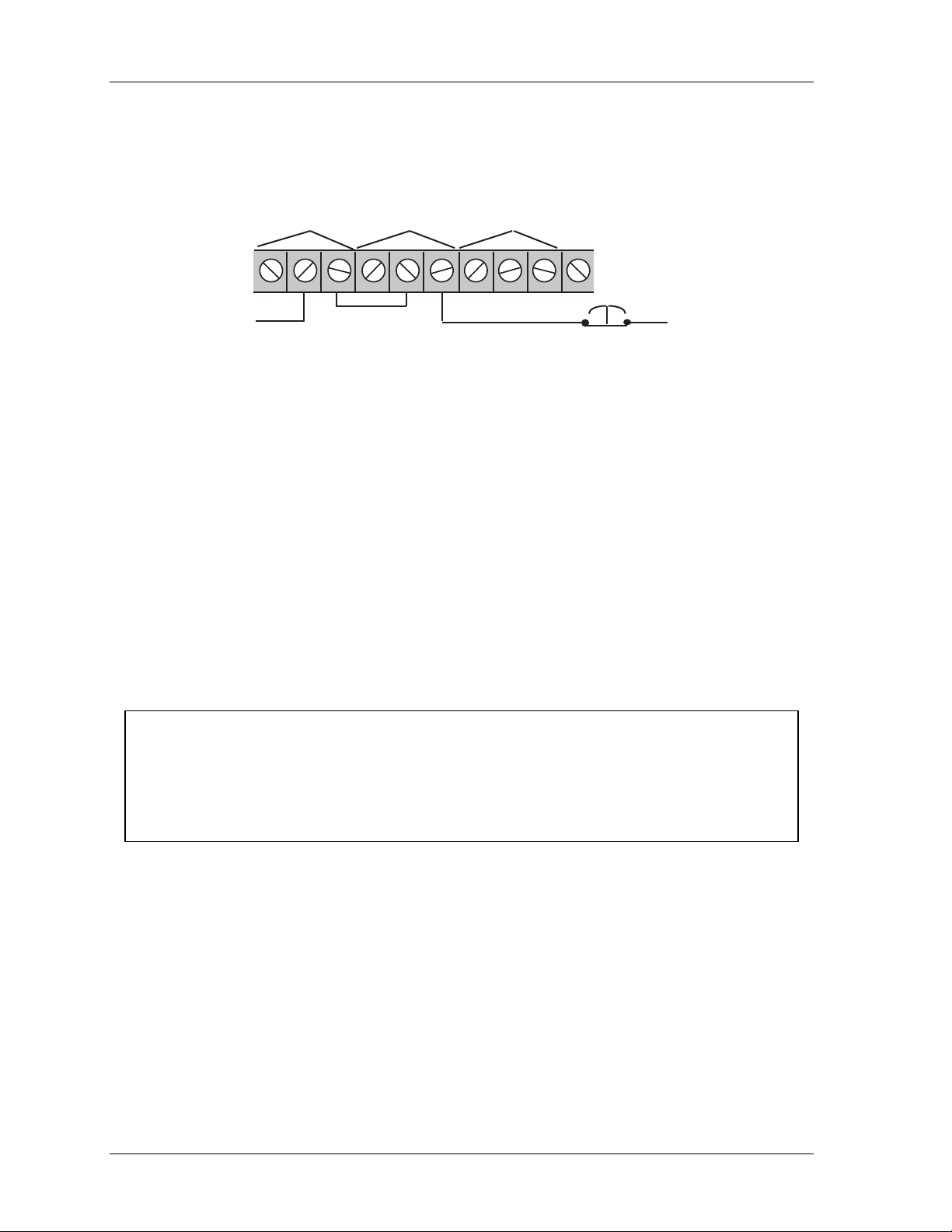
1107200 Shadow VI User Manual
If you plan to perform optional wiring (for instance — MPCE monitor inputs or external
interrupt), refer to the section "Optional Wiring", found later in this chapter for additional
information.
FSD1
(1-3)
FSD2
(4-6)
STATUS
(7-9)
TB4
immediate stop
Figure 2-19. Relays Wired to Emergency Stop Circuit, Typical
active in all modes of operation
When wiring Shadow VI into the press circuit, you should ensure that it is active in all modes
of operation. This would include inch, single stroke, and continuous. Following this practice
will provide safety for setup personnel as well as the operator. In some cases, having
Shadow VI active in all modes may even eliminate the need for lockout during a die change.
See OSHA 1910.147 "Lockout/Tagout" for details. (Note: For PLC connections, see step
8B.)
The next set of instructions explains how to continue to wire the relays in series. Refer to the
instructions below. The corresponding wiring schematics (Figure 2) can be found at the end
of the manual.
6. Connecting in series with Machine Emergency Stop (Figure 2):
CAUTION
TERMINAL BLOCK TB4 WIRED INCORRECTLY
Wire stop circuits to the upper level of terminal block TB4, not the lower level. If you wire to
the lower level, this could damage components on the circuit board.
Failure to comply with these instructions could result in property damage.
Refer to Figure 2 to connect the two stop relays in series with the press's emergency stop
circuit. The relays, which are labeled "FSD1" and "FSD2," are located on the upper level
of the TB4 connector on the control circuit board. The descriptions of these terminal
locations are as follows:
FSD1: Final switching device #1 (stop output relay #1)
FSD2: Final switching device #2 (stop output relay #2)
At the upper level of TB4, connect pins #2 and #6 in series with the press's stop circuits.
Do not remove the factory-installed jumper across #3 and #5.
page 54 Chapter 2 Installation and Checkout
Page 67
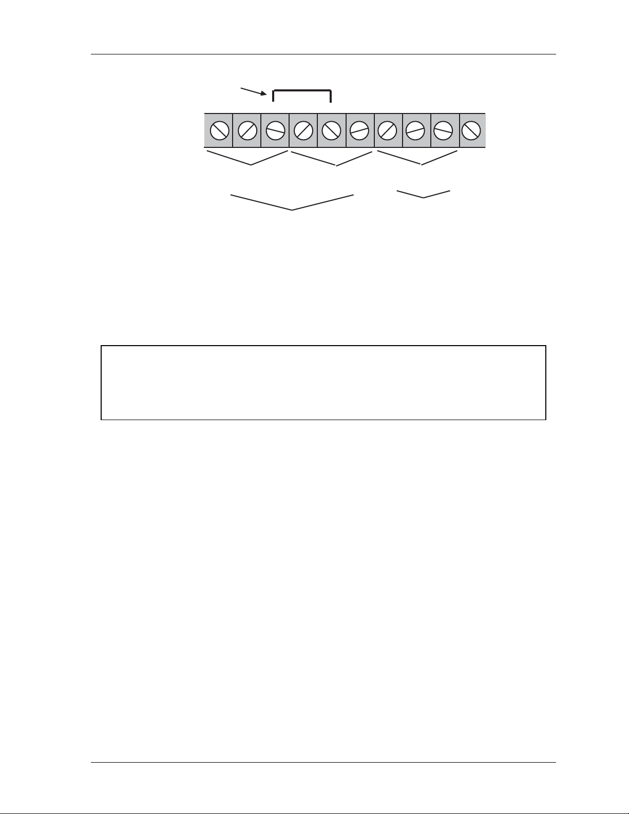
Shadow VI User Manual 1107200
factory-installed jumper
across #3 and #5
N/C N/OCom. N/C Com. N/O
N/C Com. N/O
TB4
GND
FSD1
(1-3)
Stopoutput
FSD2
(4-6)
(7-9)
Status output
Figure 2-20. Wiring "Upper" TB4 Connector in Control
7. Once you have completed the wiring of the relays (according to step 6), remember to
leave a service loop at the control to allow for later adjustment of the conduit. Cut the
wires as necessary.
Keep going in this section to connect to WPC or a PLC. If you do not need to perform either
if these installation procedures, skip to the next section "Making settings inside the control".
NOTICE
Guidelines for making these connections are covered in these steps:
8A. Wiring Shadow to the WPC
8B. Wiring Shadow to a programmable logic controller (PLC)
8A. Wiring Shadow to the WPC (One or Two Control Boxes)
If you are connecting the control to WPC, see Figure 6 at the end of this manual. To connect
2 control boxes, refer to Figure 7 also found at the end of the manual. It shows how Shadow
must be connected to the resolver-based WPC. If you have a WPC 1000 see Figure 10 at the
end of the manual. If you have an older-model WPC, refer to Figure 9 at the end of the
manual.
Once you make connections, proceed to the next section "Making settings inside the
control". If you have the optional Shadow VI-WPC control board, refer to Appendix C and
Figure 8 for specific instructions.
Installation and Checkout Chapter 2 page 55
Page 68

1107200 Shadow VI User Manual
8B. Wiring Shadow to a PLC
!
DANGER
INCORRECT WIRING TO A PLC
• Ensure that the light curtain control is properly wired to your PLC.
• Follow the guidelines in the applicable ANSI standard, ANSI B11.1. The guidelines below
serve as a reminder of the importance of connecting your light curtain correctly when using a
PLC. Do not wire the outputs in series when connecting Shadow to a PLC.
• Be aware that the details of wiring and programming the PLC are solely your responsibility,
and not Wintriss’s.
• Use a single safety PLC or multiple non-safety PLCs.
Failure to comply with these instructions will result in death or serious injury.
CAUTION
TERMINAL BLOCK TB4 WIRED INCORRECTLY
Wire stop circuits to the upper level of terminal block TB4, not the lower level. If you wire to
the lower level, this could damage components on the circuit board.
Failure to comply with these instructions could result in property damage.
When wiring the control to a Programmable Logic Controller (PLC) or other type of
microprocessor-based control, two (or more) independent logic systems should be used to
control the press's stop circuit. Wintriss does not provide specific step-by-step instructions
for connecting Shadows to PLCs. This is because of the variety of PLCs and the various
programming techniques used. Only general guidelines are supplied in this section. Refer to
Figure 4 at the end of the manual for suggested wiring.
We recommend you carefully study the ANSI guidelines in Appendix C of the ANSI B11.1
standards before connecting Shadow to a PLC. Appendix C gives detailed guidelines for
using PLCs to control the clutch and brake on metal stamping presses. Appendix C is entitled
"Some Considerations for Design of Microprocessor-Based Clutch/Brake Controls."
To ensure maximum safety, you must wire and program the PLC so it can detect an internal
component failure and immediately stop the press. Both outputs from Shadow's control
relays must be connected separately to a PLC. These outputs are marked "FSD1" and
"FSD2" (see Figure 2-20). You must remove the factory-installed jumper (as shown in
Figure 4 at the end of the manual) when connecting to a PLC.
Next, you must create a program that will check each input signal from the Shadow relays
independently. The program should stop the press immediately if the input signals ever
differ. That way, a component failure within the PLC will be immediately detected. Also,
with Shadow relays wired to the PLC separately, if one of Shadow's control relay contacts
were to weld shut preventing the stop signal to the PLC, the other relay contact would still
open to send the stop signal.
If you do not connect the control to the PLC properly, here is what could happen. A
component in the PLC fails. This causes the PLC to incorrectly read the input signals. Even
page 56 Chapter 2 Installation and Checkout
Page 69

Shadow VI User Manual 1107200
though Shadow signals a stop, the PLC does not stop the press. This situation must not be
allowed to occur.
If the control is connected to a PLC instead of directly to the machinery, then the PLC must
be able to transfer Shadow's control reliability capability to the press stop circuit. If this
capability is overridden or if the PLC cannot detect a failure of its own components, much of
Shadow's protection features are lost even though Shadow is working properly. This is why it
is essential that you do not override Shadow's control reliability features when using Shadow
with a PLC. After completing this step, proceed to the next section.
Shadow allows you to test your PLC's input modules, adding another level of safety to your
operation. Wire the PLC to the transmitter interrupt at pins #19 and #20 on TB4 auxiliary
connector. (Be sure to remove the factory-installed jumper at pins #19 and #20.) The PLC
can momentarily interrupt the transmitter's function (#19, #20 at TB4), watch the redundant
output relays open, and then resume the transmitter's operation and watch the relays close. If
the input modules do not respond properly and simultaneously, the PLC can inhibit the press
from further operation until the PLC inputs have been checked out.
Optional Wiring
This section provides instructions to wire various optional Shadow VI features, including
remote reset, indicator outputs, and MPCE monitor input.
Indicator Outputs
DANGER
!
INDICATOR OUTPUTS NOT SUITABLE FOR SAFETY USE
• DO NOT use the indicator outputs listed in the specifications table for personnel protection.
They cannot be used to stop the machinery.
• Use only the safety outputs for personnel protection.
Failure to comply with these instructions will result in death or serious injury.
You can wire up to 4 indicator outputs to customer-supplied solid-state relays.
These outputs, which are open collectors to ground, allow you to view Shadow's operating
status at a remote location by mimicking the indicators at the Shadow control. Connect the
positive input wire from your 12VDC solid-state relay to pin #5 ("V out") at TB5 connector
inside the control. Wire pins #1 (Green), #2 (Amber), #3 (Red), and #4 (Yellow) as needed
according to Figure 5 at the end of the manual.
Installation and Checkout Chapter 2 page 57
Page 70
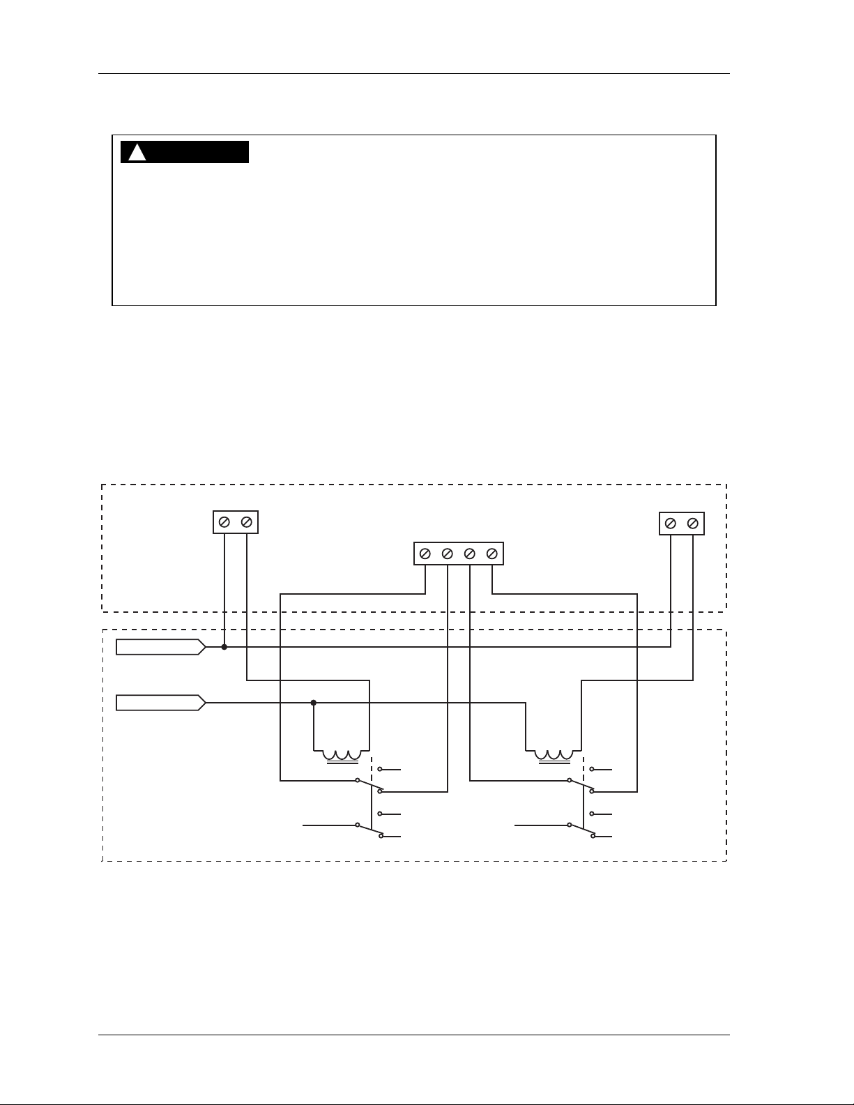
1107200 Shadow VI User Manual
MPCE Monitor Inputs
DANGER
!
MPCE INSTALLATION NOT SUITABLE FOR SAFETY USE
• Install MPCE relays in pairs as instructed in this manual.
• Use only relays with forced guided type contacts for MPCE monitoring.
• Ensure that the response time of the MPCE circuitry is less than 25 ms.
• Use only the safety outputs for personnel protection.
Failure to comply with these instructions will result in death or serious injury.
To monitor the performance of your relays with the Machine Primary Control Element
(MPCE) monitor inputs, connect the Shadow stop circuits to the interfacing relays, instead of
connecting them in series with the machine’s immediate stop circuit or with control reliable
safety relay modules.
See the figure below for an example of how to wire the MPCE inputs. Use normally closed
contacts only. To monitor external MPCEs, place jumpers J14 and J15 in the EXT (external)
position. See Figure 2-23. Call Wintriss Tech Support for further information.
Light Curtain
Control
USER POWER
Machine Primary
Control Element
(MPCE) Relays
FSD1
23
UPPER
TB4
81
3
6
MPCE1 MPCE2
11
12 13 14
K1
4
2
5
7
LOWER
TB4
81
3
6
Figure 2-21. Example of MPCE Usage
K2
4
2
5
7
UPPER
TB4
FSD2
65
page 58 Chapter 2 Installation and Checkout
Page 71
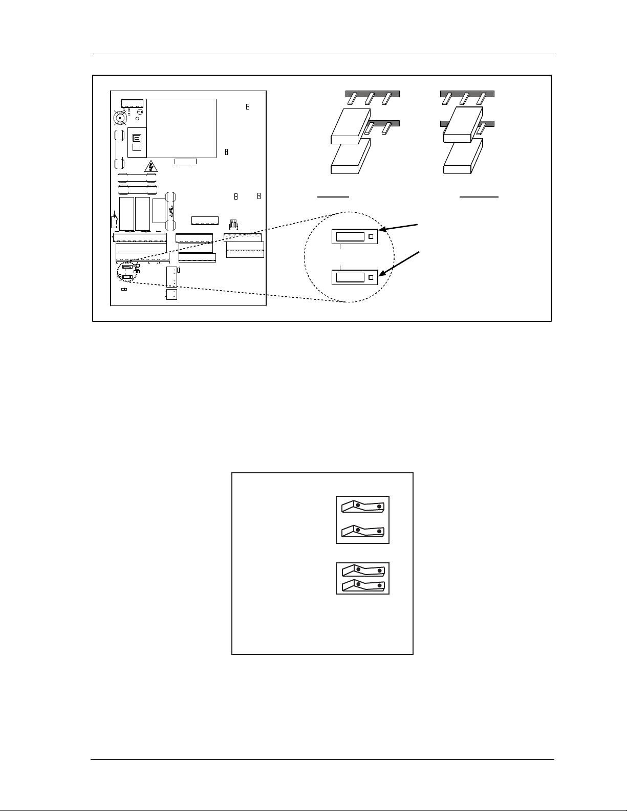
Shadow VI User Manual 1107200
1
TB1
S2
F1
115 V
F2
F3
K1 K2
J13
FSD1 FSD2 STAT
TB4
MPCE1 MPCE2 RESET XMTR INT
DS6
J15
INT
J14
DS5
DS8
K3
RESET ON
INTERRUPT
FLOATING
WINDOW
STAT=GRN
F4
GND
TB5
VCR VCC GNDSHUTDOWNSYNCSHIELD
TB3
1
VCR VCC GNDSHUTDOWNSYN CSHI ELD
ON OFF
PWR UP
RESET
DISABLE
S4
S1
OPTIONS
J11
GRN AMB RED YEL V-OUT
1
TRANSMITTER 1
TRANSMITTER 2
TB2
1
DS3
DS1
J12
1 SET
FWIN VCC GND 1A SYNC SHIELD1B
FWIN VCC GND 2A SYNCSH IELD2B
RECEIVER 2
DS4
RECEIVER 1
INT
DS2
For “Internal” place jumper
on
left-hand two pins.
J15
INT
J14
J15
J14
Figure 2-22. Setting MPCE Jumpers
Making Settings Inside the Control
INT
For “External” place
jumper on right-hand two pins.
J14
Set MPCE2 at JP15
Set MPCE1 at JP14
Note:
Factory setting is “Internal” (INT).
J15
Follow these steps to make the proper switch settings inside the control. Refer to the location
of components found at Figure 2-14. Also look at the illustrations that follow, which show
the factory settings for the switch blocks S1 and S4 and jumper block J12.
power up
reset disable
reset on
interrupt
ON OFF
S4
floating window
status relay follows
stop outputs
ON OFF
S1
factory settings: OFF
Figure 2-23. Factory Settings for Switch Blocks S1 and S4
Installation and Checkout Chapter 2 page 59
Page 72
1107200 Shadow VI User Manual
S1 settings
1. Floating window: The "off" factory setting disables this feature. Set the switch to "on"
when you want to enable this built-in floating window option. The feature provides a
means for the random bypass of only one beam of the light curtain (refer to Chapter 1 of
this manual for more detail). Notice that when this feature is enabled, the "floating
window" indicators on the control and receiver will flash on and off.
DANGER
!
STATUS OUTPUT NOT SUITABLE FOR SAFETY USE
• DO NOT use the status output for personnel protection. It cannot be used to stop the
machinery. It is intended only as a convenience to interface automation.
• Use only the safety outputs for personnel protection.
Failure to comply with these instructions will result in death or serious injury.
2. Status relay follows stop outputs: The factory setting is "off" which disables this feature.
When the switch is "on", the status relay "mimics" the output relays. This feature can be
used to turn on an alarm or beacon whenever the light curtain goes "red". No matter how
this feature is set, the status function is always active.
S4 Settings
1. Power up reset disable: The "off" setting means that when Shadow is powered up, you
must reset the system before proceeding. The "on" position disables the feature.
It is useful to keep the setting at "off". This is a reminder for you to ensure that the daily
tests on Shadow are performed as soon as the “reset required” condition has been cleared.
If your the Shadow is wired to the resolver-based Wintriss Clutch/Brake Control (WPC),
disable this functionality because WPC already has this feature.
2. Reset on interrupt: The factory setting is set to "off" which disables this feature. When
the switch is set to "on", if one or more of the light curtain beams have been obstructed,
then a “reset required” condition will occur. When the obstruction is removed, the light
curtain does not reset to "green" automatically. You must clear the condition by resetting
Shadow to resume operation. This is a useful feature for perimeter guarding applications
when there is a walk-in hazard inside the guarded area.
page 60 Chapter 2 Installation and Checkout
Page 73
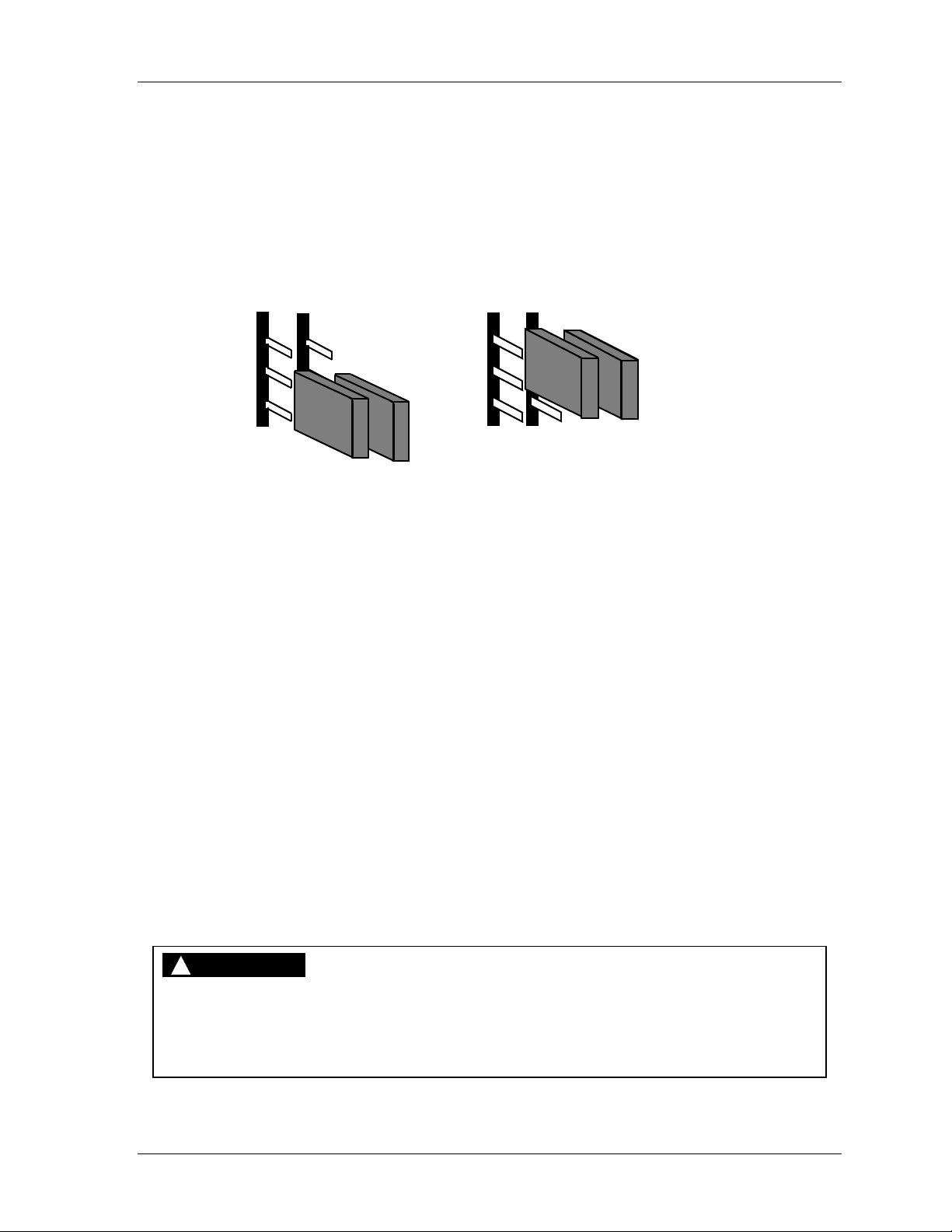
Shadow VI User Manual 1107200
J12 Setting
These instructions explain how to set Shadow for a second set of light curtains. The factory
setting is "1 SET". If you are installing a second set of heads, follow these steps.
1. Locate jumper location J12 in the control (refer to Figure 2-14 for location of
components). It is situated just above terminal block TB2 on the lower right-hand side of
the board. Notice that the jumper is set on pins 2 and 3 for "1 SET."
2. Move the jumper so that it will be on pins 1 and 2 for "2 SET."
J12
"1 SET" setting
(Jumpers on bottom 2 pins)
J12
"2 SET" setting
(Jumpers on top 2 pins)
** notice that
there are 2
jumpers side
by side at J12
Figure 2-24. Jumper Position for "1 SET" and "2 SET"
3. You will also have to perform some diagnostics to verify this setting. To do this, refer to
the section, "Aligning and tightening down Shadow VI components."
Plug in Connector and Replace Cover
Now that you have completed the wiring of the control and made the proper switch settings,
make sure all connections are properly plugged into position and that all conduits are in
place. Close the cover and tighten the locking screw on the control. Leave the transmitter
and receiver loose.
Connect 115 VAC wires from the control to the 115 VAC source. Make sure power is off
before making connections.
Now go on to the next step—aligning and tightening down your Shadow VI heads.
Aligning and Tightening Down Shadow VI Components
DANGER
!
HAZARDOUS EQUIPMENT OPERATING
Remove power from the press and other hazardous machinery while you are aligning the
light curtain transmitter and receiver.
Failure to comply with these instructions will result in death or serious injury.
Installation and Checkout Chapter 2 page 61
Page 74

1107200 Shadow VI User Manual
You have wired and loosely mounted your Shadow transmitter and receiver as directed in the
section "Loosely mounting Shadow VI transmitter and receiver". Now you need to test and
align them. Once that is done you can tighten them using the appropriate adjustment method
to keep them in alignment (such as rotating the universal mounts discussed at the beginning
of this chapter).
If you suspect a problem with Shadow, verify that the heads are properly aligned. If there is
still a problem, be sure to perform the diagnostic tests at the end of this chapter.
Alignment Procedure
If you have read the material in this chapter, you already know a lot about alignment. If the
Shadow light curtains are out of alignment, one or more light beams from the transmitter are
not being detected by the receiver. Shadow will react as if a part of the light curtain is
blocked. Its relays will be open and stay open, and your press will not operate.
Proper alignment means each beam of light from the transmitter is detected by the
appropriate phototransistor in the receiver. As long as you installed your brackets level and
in the same plane (as described in Step 2), alignment will be very easy. Here is how to align
your Shadow light curtains.
1. Make sure you have the Shadow light curtains mounted so the lenses are pointed at each
another.
2. Turn on power to the Shadow light curtains. Do not start the press. You do not need to
operate the press for this procedure.
3. Check the amber power light near the top of the transmitter cover. It should be on. If not
re-check wiring. If you cannot find the problem, contact Wintriss Tech Support.
4. Make sure the light curtain is unobstructed. Then check the lights on the receiver. A
green light means the Shadow light curtains are in alignment. A red light means they are
not aligned.
5. Whether the light is green or red, experiment a little to get a feel for how precisely
aligned you have to be. Your Shadow light curtains should be only loosely mounted.
Tighten one unit so it will not move. Using the Shadow universal mounts mentioned at
the beginning of this chapter, swivel the other one a little to see what happens. Move it a
little vertically as far as the brackets will allow. Watch the lights. Note when the Shadow
light curtains are aligned (green light on receiver on) and when they are not (red light
on).
6. Now that you have a feel for what it takes to properly align the units, get them back in
line.
7. Keep the units in alignment using the Shadow universal mounts or another method you
designed. Tighten down the transmitter to take up slack, then work on the receiver. If the
units go out of alignment, make adjustments, then start tightening again. When
everything is right, tighten down each unit firmly.
8. Check the lights on the receiver again. The light must be green. If not, make sure the
light beam is not obstructed. If the light is not green, you will have to loosen your
mounting bolts, re-align, then re-tighten.
page 62 Chapter 2 Installation and Checkout
Page 75

Shadow VI User Manual 1107200
Once your Shadow light curtains are tightened to their brackets and the light is green, you
are done aligning and mounting your Shadow light curtains. Go on to the checkout
procedure. Do not begin press operation until you have completed the checkout sequence.
Diagnostic Steps to Perform Before Using Shadow
!
DANGER
FAILURE TO PERFORM SAFETY SYSTEM TESTS
• Perform the final checkout sequence below when you have completed installation of your
light curtain, before operating the equipment it is connected to.
• Operate your machinery only after your safety system meets all the requirements of the
checkout sequence.
• Perform the final checkout sequence whenever repair, maintenance or modification is
performed on your light curtain or the machinery it is connected to.
• Perform the “daily test” safety system checkout sequence on page 93 (in French, en
Français, page 114) every day before operating any machinery connected to Shadow safety
light curtains.
Failure to comply with these instructions will result in death or serious injury.
If your Shadow light curtain does not operate correctly, use the following diagnostic steps to
troubleshoot and correct problems. If you need help, call Wintriss Tech Support.
No Power to Unit
If your light curtain has no power, check the power fuse F1. Also check that power
connections have been done correctly. These procedures are discussed in detail in the
section "Connecting AC wiring to the control" earlier in this chapter.
The Light Curtain Is in a "Reset Required" Condition
Use the reset keyswitch to clear the “reset required” condition. If this is not successful,
power the system down, then up. Again, reset the system using the reset keyswitch.
If the “reset required” condition remains, check that you have correctly set the jumper
settings for "1 set/2 sets". This is covered in "Making settings inside the control" in this
chapter.
If the Transmitter Has No Power or Is Not Functioning
Verify your transmitter wiring and that the transmitter and receiver wiring is not reversed.
Add labeling to the transmitter and receiver cables in the control if you have not already done
so. Refer to "Wiring the transmitter and receiver to the control" in this chapter.
Check Power and Indicator Lights
Make sure the transmitter's amber light and red or green lights on the receiver and at the
control are both on. Also check indicators — DS3 and DS4, located in the upper right-hand
corner of the control near the power supply. DS3 and DS4 light up green to indicate that the
optic heads are receiving power. They should be on all the time. If they are not lit, this
Installation and Checkout Chapter 2 page 63
Page 76

1107200 Shadow VI User Manual
means that either transmitter, receiver, or both may not be receiving power. If this is the case,
run a few tests. First check that the power connections at the control have been performed
correctly. (See location of components at Figure 2-14.)
If DS4 is off, test the transmitter. Unplug the quick-connect connector at the transmitter. If
DS4 turns on, this means the transmitter is defective. If the indicator stays off, reconnect the
transmitter. Next unplug the transmitter connector TB3 inside the control. If DS4 turns on,
this means the transmitter cable is shorted and needs replacement.
If DS3 is off, test the transmitter as described above. Then test the receiver. Unplug the
quick-connect connector at the receiver. If DS3 turns on, this indicates that the receiver is
defective. If the indicator stays off, reconnect the receiver. Next unplug the receiver
connector TB2 inside the control. If DS3 turns on, then the receiver cable is shorted and
needs replacement.
Continue by checking indicators DS1 and DS2, which are red indicators that are located just
above the TB2 receiver connectors at the lower right-hand corner of the board. They light up
red if you are using only 1 set of curtains and there is an obstruction, misalignment, or
indication of an internal problem. If you have two sets, refer to the section further down in
this chapter — "If you have two sets of light curtains."
Check Lens Window
If both the amber and red lights and the indicators in the control are all on, your Shadow light
curtains have power. You still need to get a green light (indicating Shadows are aligned).
Make sure there is no object in the light field which you have overlooked. Then wipe off the
lens window on each unit. It is possible that you got some substance on the lens window that
is blocking a light beam. See "Checking lens window" in Chapter 4. If the green light comes
on after you have cleaned the lens window, you are all set.
Bring Shadow Heads Close Together
If Shadow still is not working, the next step is to bring the optic heads closer. To do this,
unbolt either the receiver or transmitter (whichever is more convenient). You will take the
unbolted unit off its mounting and hold it right in front of the other. You may need to disconnect wiring so the heads will reach. Power down the control before connecting or
disconnecting the wires to the heads.
Once you have unbolted it and have wires connected, bring the unit within 6 to 11 inches of
the other. Make sure the lenses are pointed directly at one another and you have the Shadow
heads in the same plane (see Figure 2-8).
Green Light On
Shadow heads should align easily when placed very close together. If the green light is on
now, you know there is a problem with your installation. Go over the mounting instructions
in this chapter again to be sure you understand how Shadow heads should be mounted. Then
adjust your brackets. The Shadow transmitter and receiver will then align.
page 64 Chapter 2 Installation and Checkout
Page 77

Shadow VI User Manual 1107200
No Green Light
If you did not get a green light even after bringing the Shadows close together, your Shadows
probably have an internal problem. Call Wintriss Tech Support to discuss the problem.
If You Have Two Sets of Shadow Heads
If you have two sets of Shadow heads, you should already have completed the necessary
wiring explained in "Wiring Shadow heads to the control." You also made jumper settings at
J12 in the control, page 61.
Next, check how the indicators — DS1 and DS2 — are lit up in the control when either of
the two sets has been interrupted (see Figure 2-14 for location of components). DS1 and
DS2 are located just above the TB2 receiver connector at the lower right-hand corner of the
board. DS1 lights up red when Set 1 (wired to the upper connectors of TB2 and TB3) is
interrupted. DS2 corresponds with Set 2, which are wired to the lower connectors.
Green Light On But Still Cannot Start Press
!
WARNING
ELECTRIC SHOCK HAZARD
• Ensure that the power source is off before checking or replacing fuses.
• Disconnect power from the machinery it is connected to before making any wiring
connections. This includes disconnecting power to the machine control and motor.
• Ensure that all procedures are performed by qualified personnel.
Failure to comply with these instructions could result in death or serious injury.
If everything seems to be all right, but you still cannot start the press, perform the following
checks. Shut off power before checking relays so that you do not get a shock! Check if one
or more of the 3 output fuses (F2, F3, and F4) have failed. Replace if necessary. See
"Checking and Replacing Fuses" in Chapter 4. If the press still will not start, check the
control relays located above the TB4 connector inside the control. Relays have ty wraps
around them to hold them tight in their sockets. Check to make sure the ty wraps are attached
and relays are tight in their sockets. Also check to see if a relay has contacts that are welded
shut. See “Checking and Replacing Control Relays” in Chapter 4 for relay location and
procedure.
Installation and Checkout Chapter 2 page 65
Page 78
1107200 Shadow VI User Manual
Final Checkout Sequence
!
DANGER
FAILURE TO PERFORM SAFETY SYSTEM TESTS
• Perform the final checkout sequence below when you have completed installation of your
light curtain, before operating the equipment it is connected to.
• Operate your machinery only after your safety system meets all the requirements of the
checkout sequence.
• Perform the final checkout sequence whenever repair, maintenance or modification is
performed on your light curtain or the machinery it is connected to.
• Perform the “daily test” safety system checkout sequence on page 93 (in French, en
Français, page 114) every day before operating any machinery connected to Shadow safety
light curtains.
Failure to comply with these instructions will result in death or serious injury.
!
DANGER
CHANGE IN STOPPING TIME REQUIRES SAFETY DISTANCE ADJUSTMENT
• Repair your machinery stopping mechanism if its stopping time increases beyond the
acceptable limit.
• Re-calculate the light curtain safety distance, using the new stopping time.
• Adjust the location of the light curtain(s) accordingly.
• Perform the checkout sequence before operating the equipment.
Failure to comply with these instructions will result in death or serious injury.
You have followed the installation steps in this chapter to correctly install your Shadow
safety light curtains. Now perform the checkout sequence to make sure your safety system is
working properly.
You must perform a checkout sequence after mounting and wiring are complete and before
you use Shadow safety light curtains with your machine.
It is also imperative to perform the checkout sequence every time any maintenance, repair or
other modification is performed on a Shadow safety light curtain unit or on the machinery
connected to the light curtain.
NOTICE
Use opaque test bars of 1 1/4" (32 mm) and 1/8” (3.2 mm) diameter for performing the
checkout sequence. If you are using the Floating Window option, also use a 2" diameter
test bar as instructed below.
Perform the daily test in Appendix A every day before operating the press. Follow the
checkout sequence below every time you repair, maintain or modify the press.
page 66 Chapter 2 Installation and Checkout
Page 79

Shadow VI User Manual 1107200
1. Have ready 1-1/4" (32 mm) and 1/8” (3.2 mm) opaque test bars. If your light curtain has
floating window, also have ready a 2” (50.8 mm) opaque test bar. Turn on power to
Shadow safety light curtain and to the machine.
2. Make sure the floating window option has been disabled, if your light curtain has it, by
setting the "floating window" switch at switch block S1 (in the control) to the “OFF”
position (see “Making Settings Inside the Control,” page 59).
NOTICE
LIGHT CURTAINS EQUIPPED WITH FLOATING WINDOW OPTION
Indicators on the receiver and on the control blink to indicate that floating window has been
enabled. This indicator should be off when you perform this checkout procedure with the 1
¼” test bar. Later you will enable floating window and repeat the test with the 2” bar .
3. Using the 1-1/4" (32 mm) diameter test bar, interrupt the sensing field on the receiver
side by passing the test bar from the top to the bottom of the receiver's lens cover. The
red light should come on while the test bar is in the sensing field.
4. Repeat step 3, passing the 1-1/4" (32 mm) diameter test bar from the top to the bottom of
the transmitter's lens cover. The red light should stay on while the test bar is in the
sensing field.
5. Block the light curtain so that the red light is on; verify that the machine will not start
while the light curtain is obstructed.
6. Using the 1/8” (3.2 mm) diameter test bar, interrupt the sensing field on the receiver side
by passing from the top to the bottom of the receiver’s lens cover. The green light
should remain on. If the red light comes on, realign the heads to prevent nuisance stops.
7. Repeat step 6, passing the 1/8” diameter test bar from the top to the bottom of the
transmitter’s lens cover. The green light should remain on. If the red light comes on,
realign the heads to prevent nuisance stops.
NOTICE
If muting is used, interrupting the light curtain during the non-hazardous portion of the stroke
(upstroke) will not stop the machine. To test, you must interrupt the stroke on the
downstroke, which is the hazardous portion of the stroke.
8. Start the machine and interrupt the light field with the 1-1/4" (32 mm) diameter test bar.
The red indicator light on the receiver should come on and the machine should stop
immediately.
NOTICE
Step 9 applies specifically to presses with single cycle and cycle stop capability. If you
cannot single stroke or top stop your press, carry out all steps except Step 9. You must
ensure that your Shadow meets the requirements of the other steps before using the
Shadow-equipped equipment. Remember, your press must be able to stop when the light
beam is broken.
Installation and Checkout Chapter 2 page 67
Page 80

1107200 Shadow VI User Manual
9. Single stroke the machine and make sure it stops at top dead center. Make sure the
machine's braking system is working properly. If the machine does not stop fast enough,
adjust the braking system or increase the light curtain's safety distance.
10. Test the floating window option if you have it:
• If the light curtain does not have the floating window option, go to the next step.
• If your light curtains have floating window, enable it and repeat the steps above with
the 2” (50.8 mm) test bar instead of the 1 ¼” test bar.
11. You have completed the Checkout Sequence.
• If your Shadow safety light curtain performed as described in the checkout
sequence, you can now begin to operate your machinery.
• If your light curtain did not perform as indicated, and you are still experiencing
problems, refer to the complete Troubleshooting guides in Chapter 4. For further
technical assistance, call Wintriss Tech Support.
If your Shadow safety light curtain did not work exactly as described in this chapter, there is
a problem with your mounting or with the Shadow itself. DO NOT operate the machinery
until all conditions of the checkout sequence are met.
See "Chapter 4. Troubleshooting Shadow Safety Light Curtains" to see if you can solve the
problem by making some simple checks described in that chapter. If the safety system still
does not work properly, contact Wintriss Tech Support for assistance.
page 68 Chapter 2 Installation and Checkout
Page 81

Chapter 3 – Fixed and Floating Blanking
!
DANGER
INCORRECT SAFETY DISTANCE
Ensure that the correct safety distance exists between the light curtain and the hazardous
area. See Chapter 2 for detailed information on object sensitivity, depth penetration factor
and calculating the safety distance.
Failure to comply with these instructions will result in death or serious injury.
External fixed blanking is an option available with Shadow. With fixed blanking, you can
disable light beams in an area where a fixture penetrates the light field, and you can permit
stationery objects to protrude into Shadow's sensing field.
As an example, in a situation where a conveyor or work table extends into the light field, it
would not be feasible to move the fixture. Therefore, by installing a blanking window on the
Shadow receiver where the fixture penetrates the field, you disable the light beam that would
normally have detected the fixture. However, if penetration occurs anywhere above or below
the blanked beam, the light curtain will send a stop signal to the machinery.
The built-in floating window feature provides a means for the random bypass of only one
beam of the light curtain. It is useful in those applications where material or air ejected parts
randomly travel through or within the sensing field. The floating window may only be used
when material or parts take up a space no greater than 11/8" (2.9 cm) within the sensing field.
Larger material would block more than one light beam at a time. As a result, the light curtain
would generate a stop command.
You can enable the floating window feature by turning a switch "on" inside the control. The
orange indicators at the receiver and on the cover of the control flash to let you know floating
window has been enabled. Floating window automatically alters the object sensitivity from
1/4" to 2". If you use this feature, even occasionally, the safety distance for mounting must
1
be increased. Refer to "Calculating Safety Distance" in Chapter 2 of this manual.
Floating window can also be used in conjunction with fixed blanking. For example, you can
use both in an application where part of the tool protrudes into the light field and an airblow-off is ejecting parts. Instructions for installing and/or enabling both of these features
are covered in this chapter.
Shadow VI User Manual 1107200
Fixed and Floating Blanking Chapter 3 page 69
Page 82
1107200 Shadow VI User Manual
Blanking Windows Affect Safety Distance
!
DANGER
INCORRECT SAFETY DISTANCE
Ensure that the correct safety distance exists between the light curtain and the hazardous
area. See Chapter 2 for detailed information on object sensitivity, depth penetration factor
and calculating the safety distance.
Failure to comply with these instructions will result in death or serious injury.
!
DANGER
UNPROTECTED ZONE DUE TO EXTRA BLANKING WINDOWS
• DO NOT blank more than two beams of the light curtain unless a conveyor or other object
completely fills the blanked area, or if you use barrier guards to block any unfilled areas.
• Remove blanking windows when they are no longer needed.
• Maintain access to blanking master and slave windows under supervisory control to avoid
unauthorized usage.
Failure to comply with these instructions will result in death or serious injury.
IMPORTANT
Refer to Chapter 2 in this manual for more information on safety distance, object sensitivity,
and depth penetration factor.
If you use a blanking window or floating blanking window, safety distance is affected,
because the sensitivity of the light curtain is altered. The minimum size that Shadow can
sense is an object 11/4" (3.2 cm) in diameter. This diameter, called the object sensitivity of
the light curtain, is the smallest diameter object that Shadow will detect anywhere in its field.
Anything smaller might fit between two light beams.
You must also consider the depth penetration factor (Dpf) which is 3.3" (8.4 cm) for an
unblanked Shadow. This factor represents how far an object, such as an operator's hand, can
move through the light path before the light curtain reacts. Depth penetration factor and
object sensitivity are interrelated.
A blanking window blocks one light beam, creating an additional
3/4" (1.9 cm) passageway
through the light field where no object will be detected. Now the object sensitivity equals 2"
(5.08 cm) wide (1
1/4"+ 3/4") and the depth penetration factor is 5.9" (15 cm).
The ANSI safety distance formula stipulates that if object sensitivity increases, the safety
distance must also be increased. This means that using fixed or floating blanking will require
moving the light curtain farther back from the hazardous area.
page 70 Chapter 3 Fixed and Floating Blanking
Page 83
Shadow VI User Manual 1107200
Adding to Safety Distance for Fixed Blanking
!
DANGER
INCORRECT SAFETY DISTANCE WHEN USING BLANKING WINDOWS
• Ensure that the correct safety distance exists between the light curtain and the hazardous
area. See Chapter 2 for detailed information on object sensitivity, depth penetration factor
and calculating the safety distance.
• When more than one beam is blanked, but the blanked area is not completely obstructed,
the depth protection factor is at least 36” (914.4 mm).
• Maintain access to blanking master and slave windows under supervisory control to avoid
unauthorized usage.
• Remove blanking windows when they are no longer needed.
Failure to comply with these instructions will result in death or serious injury.
Use this rule of thumb for increasing safety distance. Add 2.6" (6.6 cm) to the calculated
safety distance for every blanking window used.
On the other hand, if the blanked area is entirely blocked by a fixture from the transmitter to
the receiver such that operator intrusion into this area is impossible, then you do not have to
change the safety distance. For instance, you might have a work table that extends into the
light field but takes up the whole space between the transmitter and receiver which is
unprotected by the light curtain.
Adding to Safety Distance for Floating Window
!
DANGER
INCORRECT SAFETY DISTANCE WHEN USING FLOATING WINDOW
• Ensure that the correct safety distance exists between the light curtain and the hazardous
area. See Chapter 2 for detailed information on object sensitivity, depth penetration factor
and calculating the safety distance.
• Add 2.6” (6.6 cm) to the calculated safety distance when you use floating window. This
compensates for the change in object sensitivity to 2” from 1 ¼”.
Failure to comply with these instructions will result in death or serious injury.
As with fixed blanking, using the floating blanking window feature affects safety distance
because the sensitivity of the light curtain is altered. If you enable the floating window option
in the control, add 2.6" (6.6 cm) to your calculated safety distance. By doing this, you
compensate for the increased object sensitivity when floating window is enabled (from 11/4"
to 2").
Fixed and Floating Blanking Chapter 3 page 71
Page 84
1107200 Shadow VI User Manual
Installing Blanking Windows
Blanking windows are easy to install. If you are blanking more than one beam, you attach the
master blanking window first and connect "slave" blanking windows above
the blanked area. The maximum number of beams that can be blanked is 5.
Because blanking windows attach to the receiver, they are clearly visible to personnel. As a
result, it is obvious when a beam is blanked.
Installing the Master
!
DANGER
INCORRECT SAFETY DISTANCE WHEN USING BLANKING WINDOWS
• Ensure that the correct safety distance exists between the light curtain and the hazardous
area. See Chapter 2 for detailed information on object sensitivity, depth penetration factor
and calculating the safety distance.
• When more than one beam is blanked, but the blanked area is not completely obstructed,
the depth protection factor is at least 36” (914.4 mm).
• Maintain access to blanking master and slave windows under supervisory control to avoid
unauthorized usage.
Failure to comply with these instructions will result in death or serious injury.
it. This increases
!
DANGER
UNPROTECTED ZONE DUE TO EXTRA BLANKING WINDOWS
• DO NOT blank more than two beams of the light curtain unless a conveyor or other object
completely fills the blanked area, or if you use barrier guards to block any unfilled areas.
• Remove blanking windows when they are no longer needed.
• Maintain access to blanking master or slave windows under supervisory control to avoid
unauthorized usage.
Failure to comply with these instructions will result in death or serious injury.
NOTICE
Install the master blanking window at the lowest blanked beam. Install slaves above the
master.
Here are steps to install the master blanking window. If you are blanking more than one
beam, you attach the master blanking window first and connect slave blanking windows
it (installing slaves is discussed in the next section).
above
1. Locate the master blanking window. Notice a cable is attached at one end. The other
end of the cable has a connector that screws into the mating connector at the top of the
receiver. See the illustration in Figure 3-1 to locate each component.
2. The master blanking window attaches to the receiver by sliding it down from the top (it
can also be slid up from the bottom). Determine which light beam to blank. If you
page 72 Chapter 3 Fixed and Floating Blanking
Page 85
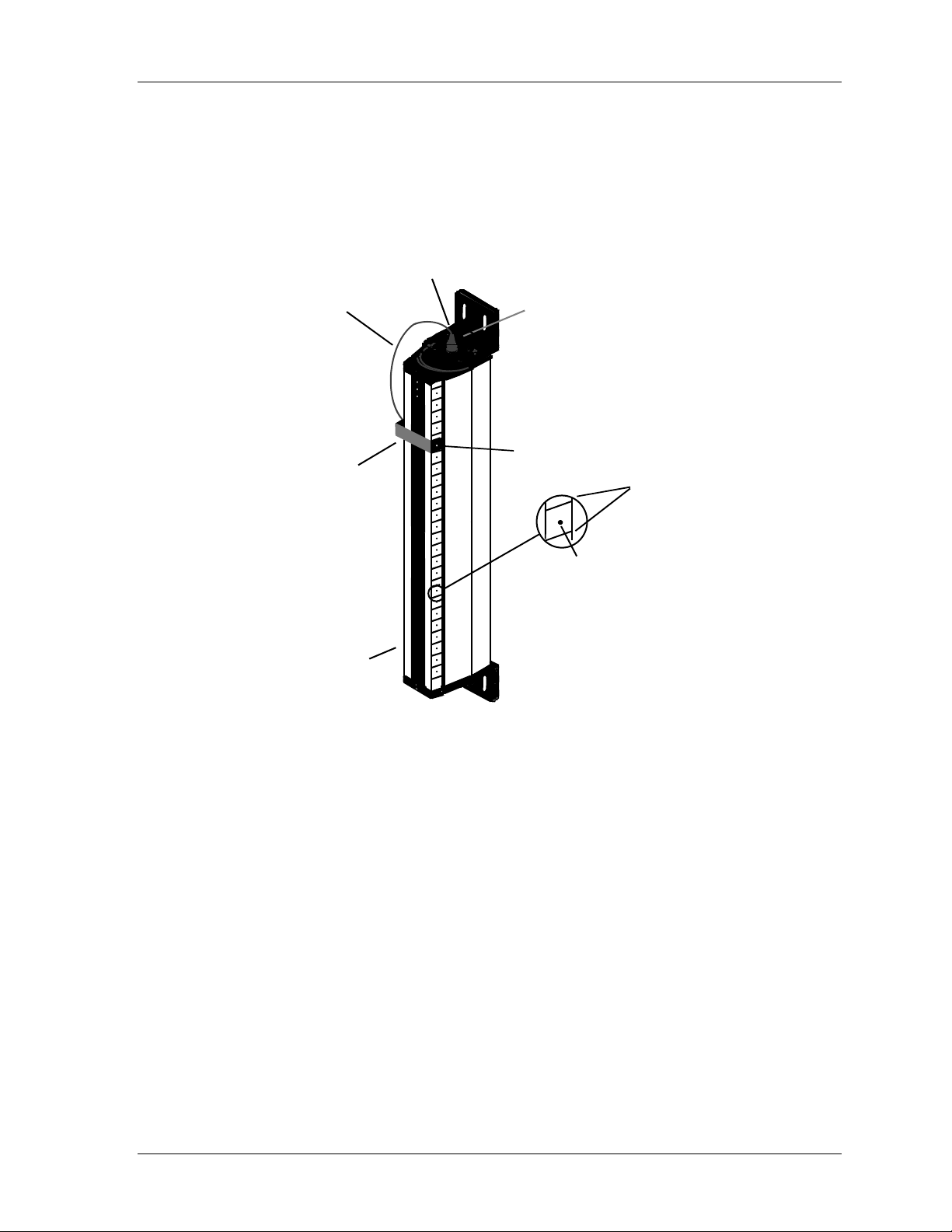
Shadow VI User Manual 1107200
intend to blank more than 1 beam, install the master blanking window on the lowest
blanked beam at this time. (The next section explains how to install the slave.)
3. Position the master blanking window over the front of the receiver. Loosen the
thumbscrew on the right side. This will allow it to slide down easily.
blanking window connector
cable attache s
at top
(must not
interfere with
light beams)
master
blanking
window
receiver
remove protectiv e
cap to attach cable
thumbscrew
alignment
indicators
mating
hole
Figure 3-1. Connecting Master Blanking Window
Fixed and Floating Blanking Chapter 3 page 73
Page 86
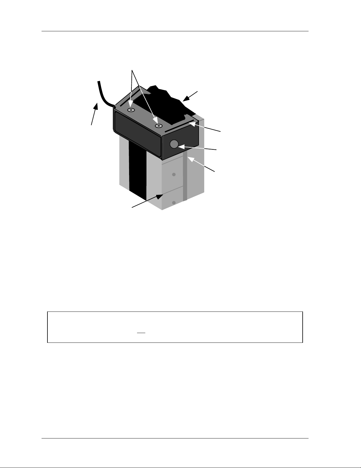
1107200 Shadow VI User Manual
plastic coverings have
been removed to allow
stacked windows
cut-away representing
top of receiver
part of
master cable
shown
(no cable with slave)
alignment
indicators
grooves on window helps fit
one on top of the other
thumbscrew
slide blanking
window up or
down the groove
on receiver
Figure 3-2. Close-up — Installing Blanking Window
4. Press down firmly on the blanking window, and line it up between the alignment
indicators on the receiver. If you need to adjust the blanking window back up, press
down on the top of the receiver end cap as you push the master upward.
5. Once the blanking window is in the desired location, retighten the thumbscrew so it fits
firmly into the mating hole.
6. Next, guide the master blanking cable to the top of the receiver.
NOTICE
Be careful that the cable does not interfere in any way with the light path. If the cable is
routed in front of the receiver, you may inadvertently be blocking other light beams.
7. Locate the plastic cap attached to the mating connector at the top of the receiver. If it is
difficult to remove, carefully unfasten it from the threads by twisting and turning back
and forth. Once the cap is removed, the cable connector goes into that location.
8. Position the blanking window connector directly over the keyed connector at the top of
the receiver. The keyed connector has three pins which must fit into holes in the cable
connector. Twist the connector slightly until you feel the pins fit into the base. Then
screw the nut on the connector to tighten the cable connector in place.
page 74 Chapter 3 Fixed and Floating Blanking
Page 87
Shadow VI User Manual 1107200
9. Notice the 2 tiny plastic coverings on the top of the master blanking window. These
should remain in place unless you plan to add more slave blanking windows (next
section).
10. You are done connecting the master blanking window. The beam you selected has been
physically disabled. It will not detect any object penetrating the light path.
Installing Slave Windows
!
DANGER
INCORRECT SAFETY DISTANCE WHEN USING BLANKING WINDOWS
• Ensure that the correct safety distance exists between the light curtain and the hazardous
area. See Chapter 2 for detailed information on object sensitivity, depth penetration factor
and calculating the safety distance.
• When more than one beam is blanked, but the blanked area is not completely obstructed,
the depth protection factor is at least 36” (914.4 mm).
• Maintain access to blanking master and slave windows under supervisory control to avoid
unauthorized usage.
Failure to comply with these instructions will result in death or serious injury.
!
DANGER
UNPROTECTED ZONE DUE TO EXTRA BLANKING WINDOWS
• DO NOT blank more than two beams of the light curtain unless a conveyor or other object
completely fills the blanked area, or if you use barrier guards to block any unfilled areas.
• Remove blanking windows when they are no longer needed.
• Maintain access to blanking master or slave windows under supervisory control to avoid
unauthorized usage.
Failure to comply with these instructions will result in death or serious injury.
You can add up to 4 slave blanking windows to the master. Follow these steps.
1. Locate the slave blanking window. If you have more than 1 slave, repeat these steps for
each.
2. Just as with the master, the slave blanking window attaches to the receiver by sliding it
down from the top (must be above the master or another slave). See Figures 3-1 and 3-2
from the previous section.
NOTICE
The master blanking window must always be installed at the lowest blanked beam. Install
slaves above the master.
3. Remove the 2 tiny plastic coverings on the top of the master blanking window.
Remember these should only be removed when you plan to add slave blanking windows.
4. Position the slave window over the front of the receiver. Loosen the thumbscrew on the
right side of the slave window. This will allow it to slide down easily.
Fixed and Floating Blanking Chapter 3 page 75
Page 88

1107200 Shadow VI User Manual
5. Press down firmly on the slave blanking window so that it lines up between the alignment
indicators on either side of the receiver. Make sure that the pins in the slave blanking
window fit properly into the mating connector holes on the top of the master. If you need
to adjust the blanking window back up, press down on the top of the receiver end cap as
you push the slave upward.
6. Retighten the thumbscrew on the slave window so it fits firmly into the mating hole.
Notice that there is no cable or cable connection that needs to be made for the slave.
7. If you need a larger blanked area, you can add another slave window (up to 4 slaves).
Repeat the previous steps. Remember to remove the 2 tiny plastic coverings at the top of
the lower slave window. Then carefully fit the pins at the upper slave window into the
mating holes at the lower one.
page 76 Chapter 3 Fixed and Floating Blanking
Page 89
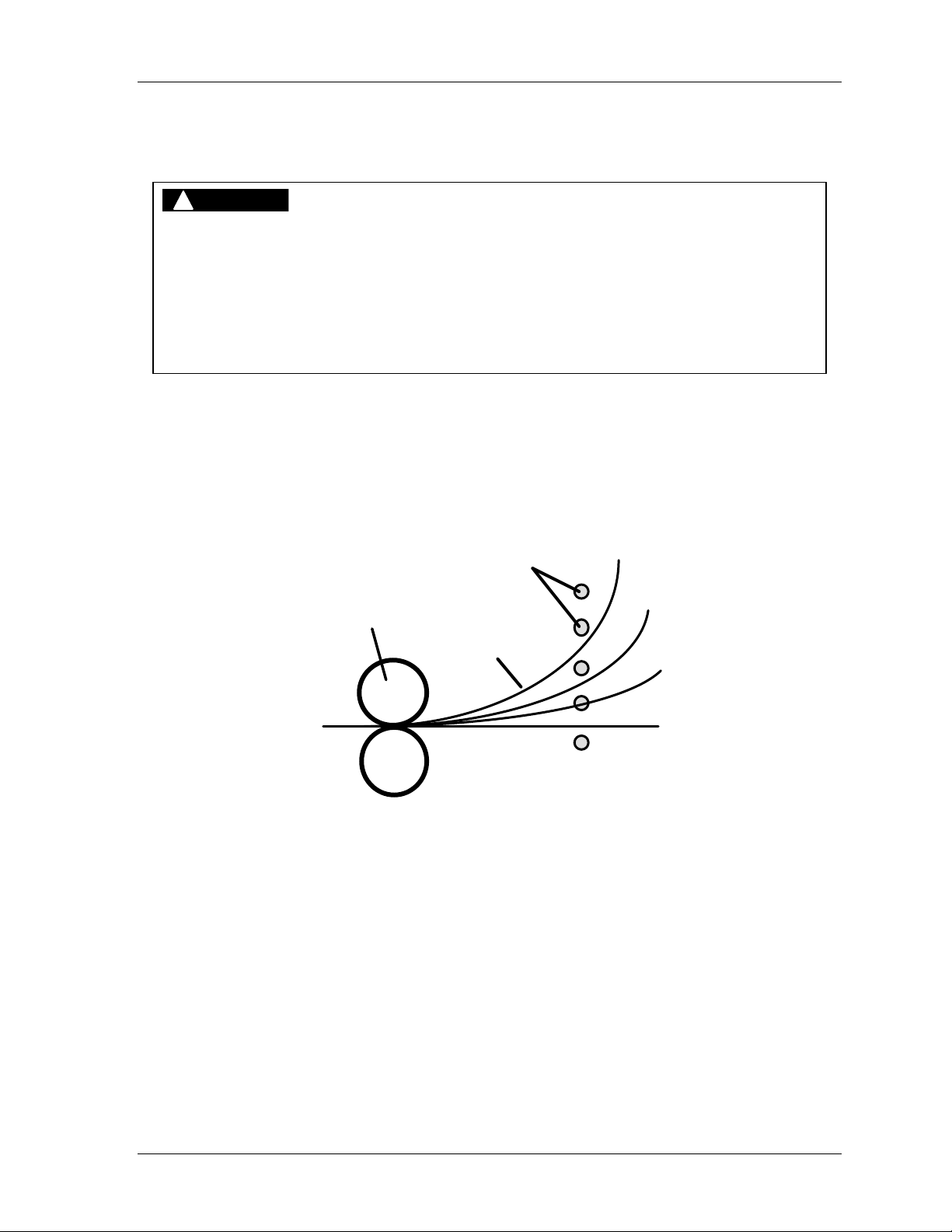
Shadow VI User Manual 1107200
Floating Window
!
DANGER
INCORRECT SAFETY DISTANCE WHEN USING FLOATING WINDOW
• Ensure that the correct safety distance exists between the light curtain and the hazardous
area. See Chapter 2 for detailed information on object sensitivity, depth penetration factor
and calculating the safety distance.
• Maintain access to blanking windows and floating window under supervisory control to avoid
unauthorized usage.
Failure to comply with these instructions will result in death or serious injury.
The built-in floating window feature provides a means for the random bypass of only one
beam of the light curtain. It is useful in those applications where material or air ejected parts
must pass through, or move within the sensing field in a random pattern.
The next illustration shows how coil stock cuts different light beams as the coil unwinds. As
long as only one beam is cut at a time (no matter which one it is), Shadow continues to allow
machinery to operate.
light beams
straightener
coil stock
Figure 3-3. Coil Stock Unwinding Using Floating Window
The floating window may only be used when material or parts take up a space no greater than
1
1/8" (2.9 cm) within the sensing field. Larger material would block more than one light
beam at a time and send a stop command.
Fixed and Floating Blanking Chapter 3 page 77
Page 90

1107200 Shadow VI User Manual
Adding to Safety Distance for Floating Window
!
DANGER
INCORRECT SAFETY DISTANCE WHEN USING FLOATING WINDOW
• Ensure that the correct safety distance exists between the light curtain and the hazardous
area. See Chapter 2 for detailed information on object sensitivity, depth penetration factor
and calculating the safety distance. If you purchased Shadows with a floating window, you
must add 2.6" (6.6 cm) to the safety distance. This 2.6" (6.6 cm) addition compensates for
the change in object sensitivity of Shadows with floating windows (from 1 1/4" to 2").
• Maintain access to blanking windows and floating window under supervisory control to avoid
unauthorized usage.
Failure to comply with these instructions will result in death or serious injury.
As with fixed blanking, using the floating blanking window feature affects safety distance
because the sensitivity of the light curtain is altered. If you enable the floating window
option, add 2.6" (6.6 cm) to your calculated safety distance. By doing this, you compensate
for the change in object sensitivity when floating window is enabled (from 11/4" to 2").
How to Enable the Floating Window
The floating window feature is enabled by turning a switch "on" at switch block S1 inside the
control. This procedure is explained in detail in the section "Making switch settings" in
Chapter 2. The indicators both on the receiver and on the front of the control will flash,
reminding you that floating window has been enabled.
page 78 Chapter 3 Fixed and Floating Blanking
Page 91

Chapter 4 – Troubleshooting Shadow VI
!
DANGER
UNAUTHORIZED REPAIRS
• Replace only the control relays, fuses and indicator lamps.
• Obtain replacement control relays, fuses and indicator lamps from Wintriss Controls.
• DO NOT replace any other components. If you do, this will violate the warranty.
• Ensure that repairs are made by qualified personnel. Improper repair by unqualified
personnel may put operators at risk of injury.
Failure to comply with these instructions will result in death or serious injury.
CAUTION
MAKING OR BREAKING CONNECTIONS WITH POWER ON
Power down Shadow before connection or disconnecting any connections at the control,
transmitter or receiver.
Failure to comply with these instructions could result in property damage.
Shadow VI has complex electronics. You should not attempt to test or repair components on
the Shadow circuit boards unless authorized to do so. That level of troubleshooting and
repair must be left to technicians trained in Shadow operation.
However, there are some tests and repairs you can perform yourself, and they are included in
this chapter. In many cases, you will be able to get an inoperative Shadow working again just
by changing a blown fuse, replacing control relays, or re-aligning.
How to use this chapter
This chapter covers how to make some Shadow repairs and adjustments and includes several
troubleshooting procedures. Two charts found at the beginning can be used as quick
troubleshooting reference guides.
Start with Table 4-1. This chart is useful if your Shadow VI comes with either 1 or 2 sets of
optic heads. The first column provides common symptoms. The next columns identify how
the indicators will or will not light up when the symptoms occur. The "Action" column
briefly recommends steps to take to correct the problem. The last column "Chapter
Reference" tells you where to go in the manual (if applicable) for complete, detailed
instructions. Table 4-2 refers to those systems with 2 sets of optic heads. In this chart there
is an extra column (first one) which identifies which set of optic heads is affected and how it
corresponds with the "indicator" columns. Following the charts there are checks that you can
make yourself, if your Shadow stops working or gives you trouble.
Shadow VI User Manual 1107200
Troubleshooting Shadow VI Chapter 4 page 79
Page 92

1107200 Shadow VI User Manual
• Checking and Cleaning Lens Window(s), page 87
• Checking Alignment, page 87
• Checking and Replacing Fuses, page 88
• Checking and Replacing Control Relays, page 89
• Checking and Correcting Cross Talk, page 91
For many of the procedures provided, you can correct the problem yourself. However, if you
find serious problems, the defective component (optic head or control circuit board) must be
factory-repaired. However, once you know which unit is bad, you may be able to substitute
another unit for the faulty one until the repairs are made.
Description of Shadow VI Indicators
Shadow includes several indicators. Figure 1-1 in Chapter 1 shows the indicators on the
transmitter and receiver, and Figure 1-2 illustrates the control.
These indicators communicate Shadow's operating status. Use them to troubleshoot your
light curtain (refer to the Troubleshooting guides that follow). If a contradiction exists
between the indicator lights at the receiver and those at the control, make sure you compare
your findings with the information in these troubleshooting guides to solve the problem
immediately.
At the Optic Heads
The transmitter has an amber-colored power indicator which remains illuminated when
Shadow has power. There are three indicators on the front of the receiver. The red
indicator means that the light curtain has been interrupted. The orange indicator flashes
when the floating window option is turned "on" at the control (see Chapter 2). The green
indicator means the light curtain is unobstructed.
At the Control
Four indicators appear on the front cover of the control and are clearly labeled. The green
"curtain clear" indicator means that the light curtain is unobstructed and the machinery will
be allowed to operate (the control relay contacts are held closed or in the unobstructed/
energized state). The "floating window" indicator lights up amber when this blanking
feature is enabled inside the control (see Chapter 2). The "stop signal" indicator goes red
when the light curtain is obstructed, the control relay contacts are open (or in the deenergized state) and the press is disabled, or when Shadow has detected an internal
malfunction. The yellow "reset required" indicator signifies that a reset-required condition
exists. This could occur during power-up, when certain settings are enabled at the control
(see Chapter 2), or if Shadow detects an internal malfunction with the components
(transmitter, receiver, or control).
page 80 Chapter 4 Troubleshooting Shadow VI
Page 93

Shadow VI User Manual 1107200
Inside the Control
There are eight LED indicators on the circuit board inside the control (refer to Figure 2-14 in
Chapter 2 for location of components).
DS1 and DS2 are located just above the TB2 receiver connectors at the lower right-hand
corner of the board, and do not light up under normal conditions. However, they light up red
if you are using only 1 set of curtains and there is an obstruction. If you have 2 sets, DS1
lights up red when Set 1 (wired to the upper connectors of TB2 and TB3) is interrupted. DS2
corresponds with Set 2, which are wired to the lower connectors.
DS3 and DS4, located in the upper right-hand corner of the control near the power supply,
normally light up green all the time, indicating that the optic heads are receiving power.
DS5 and DS6 are located in the lower left corner of the board below TB4. They light up
orange when you are using external MPCE monitoring and there is an obstruction in the
light field. See “External MPCE Monitoring: Checking DS5 and DS6” on page 85.
DS7 is located in the lower left corner of the board below TB4. It is off under norm
al
conditions, but lights up yellow when “Reset” is on.
DS8 is located in the lower left corner of the board. Under normal conditions, it lights up
green, indicating that the transmitter is active.
Troubleshooting Shadow VI Chapter 4 page 81
Page 94
1107200 Shadow VI User Manual
r
Table 4-1. Shadow troubleshooting guide for 1 or 2 sets
Receiver
Description
No power to unit. Off Off All
Optic heads are
blocked.
Machine will not
start.
(Scenario 1)
Machine will not
start.
(Scenario 2)
Transmitte
Off
Amb Red Red Red 3 Grn
Amb Grn Grn Off 3 Grn
Amb Grn Red Red 3 Grn
Control
Indicators
*
Off Off 7 Off
4 Grn
4 Grn
4 Grn
8 Off
7 Off
8 Grn
7 Off
8 Grn
7 Off
8 Off
Action
1. Check power fuse F1.
2. Check power connection.
1. Make sure a part of the machinery or other object is not
inadvertently protruding into the light field.
2. Clean lens cover(s) if necessary.
3. Check alignment. Realign if necessary.
1. Check if one or more of the 3 output fuses (F2, F3 or
F4) has failed. Replace if necessary.
2. Check if one or more of the 3 output relays has failed
OPEN (high resistance). Replace if necessary.
3. If you are not using the MPCE or transmitter interrupt
inputs, make sure the appropriate jumpers are in place
at TB4. See “Wiring
Curtain.”
4. If you are using one or more of the inputs listed above,
the user interfacing relay circuit(s) should be
CLOSED. If any user interfacing relay circuit is
OPEN, replace the relay or repair the circuit as
necessary.
5. To further troubleshoot your MPCE monitoring
circuit, see “External MPCE Monitoring: Checking
DS5 and DS6” on page 85.
1. If you have an external Transmitter interrupt circuit,
check to make sure it is operating properly. Repair if
necessary.
2. If you do not have an external Transmitter Interrupt
circuit, check the XT INT (transmitter interrupt)
jumper on lower TB4, between pins 19 and 20, to
make sure it is correctly installed and not loose.
3. Contact Wintriss Tech Support.
Shadow 3 X Series Light
Chapter ref.
.
4
2
-
4
2, 4
4
4
2
-
4
2
-
* “Red” = One or both of these LEDs light up red. “Off” = both are off.
page 82 Chapter 4 Troubleshooting Shadow VI
Page 95
Shadow VI User Manual 1107200
r
Table 4-1. Shadow troubleshooting guide for 1 or 2 sets (continued)
Description
Unit is in “reset
required”
condition.
(Note NOTICE
message below.)
Cannot reset
(Scenario 1)
Cannot reset
(Scenario 2)
Receiver
Indicators
Transmitte
Amb Grn Red
Amb Red Red
Amb Grn Red
+
Yel
+
Yel
+
Yel
Control
DS1 & 2
*
Off 3 Grn
Red 3 Grn
Off 3 Grn
4 Grn
4 Grn
4 Grn
Action
7 Off
1. Turn reset keyswitch to Reset.
8 Grn
2. Power down, then up. Turn reset keyswitch to
Reset.
3. Make sure that 115 V/230V switch inside control is
set correctly.
4. Check both jumpers at J12 (1 SET vs.
2 SET designation) are set correctly.
5. Check for loose output relays. If any
are loose, tighten ty-wraps.
6. Check that the factory-installed jumper at TB4 (stop
outputs terminal block) is intact and not loose.
7. Check relays for weld shut or stuck open.
7 Off
1. Remove any obstructions between the optic heads.
8 Grn
7 Yel
8 Grn
Follow the instructions under “Optic heads are
blocked” at beginning of this table.
1. Check reset key to see if it is stuck in the “Reset”
position. If it is, contact Wintriss Tech Support.
2. Check your external reset circuit to see if it is
stuck “on.” If it is, repair it.
Chapter ref.
.
-
2
2
4
2
2
-
NOTICE
You cannot clear a “reset required” condition unless the optic heads are properly aligned and the
indicator(s) on the receiver(s) light up green. If the receiver(s) indicate a red condition, you will
not be able to reset the system by turning the reset keyswitch on the control. You first must
properly align the optic heads and check that the indicator(s) light up green.
(1 or
both)
3 Grn
4 Grn
4 Off
7 Off
1. Check transmitter wiring.
8 Grn
2. Check whether transmitter and receiver wiring is
reversed. If you cannot trace the cables, go to the
section that immediately follows Table 4-2 for
further action.
7 Off
1. Unplug transmitter connector at transmitter. If DS4
8 Grn
turns ON, transmitter is defective.
2. If DS4 stays OFF, reconnect transmitter. Unplug
transmitter connector at control. If DS4 Turns ON,
transmitter cable is shorted and must be replaced.
Transmitter has
no power or is not
functioning.
Transmitter power
supply is not
functioning.
Off Red Red Red
Off Red Red Red 3 Grn
* “Red” = One or both of these LEDs light up red. “Off” = both are off.
2
2
2
2
Troubleshooting Shadow VI Chapter 4 page 83
Page 96
1107200 Shadow VI User Manual
r
Table 4-1. Shadow troubleshooting guide for 1 or 2 sets (cont.)
Description
Receiver head is
not getting power.
OR
Transmitter logic
is not getting
power.
Receiver “green”,
but control box
“red.”
(Scenario 1)
Receiver “green”,
but control box
“red.”
(Scenario 2)
Control
DS1 & 2
Receiver
Transmitte
Amb Off Red Red 3 Off
Amb Grn Red Red 3 Grn
Amb Grn Red Off 3 Grn
Indicators
*
4 Grn
4 Grn
4 Grn
Action
7 Off
1. Unplug receiver connector at receiver.
8 Grn
7 Off
8 Grn
7 Off
8 Grn
If DS3 turns ON, receiver is defective.
2. If DS3 stays OFF, reconnect receiver.
Unplug receiver connector at control. If
DS3 turns ON, receiver cable is shorted
and must be replaced.
3. Unplug transmitter connector at transmitter.
If DS4 turns ON, transmitter is defective.
4. If DS4 stays OFF, reconnect transmitter. Unplug transmitter connector at
control. If DS4 Turns ON, transmitter
cable is shorted and must be replaced.
1. Check wiring at control box terminal block
(TB2), which goes to receiver.
2. Using a digital voltmeter, measure the
AC voltage between outputs and ground:
Set #1: between pins 4 & 7 and 5 & 7.
Set #2: between pins 11 & 14 and
12 & 14.
Voltage in each case should read between
5.1 and 5.2 volts.
3. If voltage is 0, receiver connector might be
cross-threaded. Unscrew receiver quickconnect cable and plug back in. Remeasure the voltage as in step 2.
4. If voltage is still 0, replace cable.
5. If none of the above works, receiver has a
hardware failure. Contact Wintriss Tech
Support to replace receiver.
1. This indicates a power supply failure.
Contact the factory for assistance.
Chapter ref.
.
2
2
2
2
2
2
-
* “Red” = One or both of these LEDs light up red. “Off” = both are off.
page 84 Chapter 4 Troubleshooting Shadow VI
Page 97
Shadow VI User Manual 1107200
r
External MPCE Monitoring: Checking DS5 and DS6
These LEDs help diagnose problems relating to external MPCE monitoring. If you are using
external MPCE monitoring do the following:
1. Block the light curtain and look at LEDs DS5 and DS6 (see Figure 2-14 for location).
They should both light up orange.
2. If only one lights up, or if neither lights up, check the machine control circuit.
3. Verify that MPCE wiring is correct and check that MPCE jumpers J14 and J15 are both
set for “external.” See Chapter 2.
Set
#1
#2
#1
#2
#1
#2
#1
#2
#
Set #1 optic heads
are blocked.
Set #2 optic heads
are blocked.
Sets #1 and #2
optic heads are
both blocked.
OR
Transmitter #1 is
wired with
receiver #2 and
vice versa.
Relays are
chattering on
and off.
Table 4-2. Shadow Troubleshooting Guide for 2 Sets
Control
Action
DS1 & 2
Description
Transmitte
Amb
Amb
Amb
Amb
Amb
Amb
Amb
Amb
Receiver
Red
Grn
Grn
Red
Red
Red
Grn
Grn
Indicators
Red
Red
Red
Flicker
betw/
Grn &
Red
1 Red
2 Off
1 Off
2 Red
1 Red
2 Red
1 Off
2 Off
3 Grn
4 Grn
3 Grn
4 Grn
3 Grn
4 Grn
3 Grn
4 Grn
7 Off
1. Make sure a part of the machinery or
8 Grn
7 Off
8 Grn
7 Off
8 Grn
7 Off
8 Grn
other object is not inadvertently
protruding into the light field.
2. Check lens cover(s) for dirt buildup
and clean if necessary.
3. Check alignment. Realign if necessary. 2
1. Complete steps 1, 2 and 3, above.
2. If this does not solve the problem, check
to see if transmitter and receiver
connections are reversed. If you cannot
trace the problem, go to the section that
immediately follows this table for
further instructions.
1. Optic head jumper setting is incorrect (1
set vs. 2 sets). Check that both
“1 set/2 sets” jumpers at J12 are set at
“2 sets.”
Chapter ref.
.
-
4
4, 2
2
2
Troubleshooting Shadow VI Chapter 4 page 85
Page 98
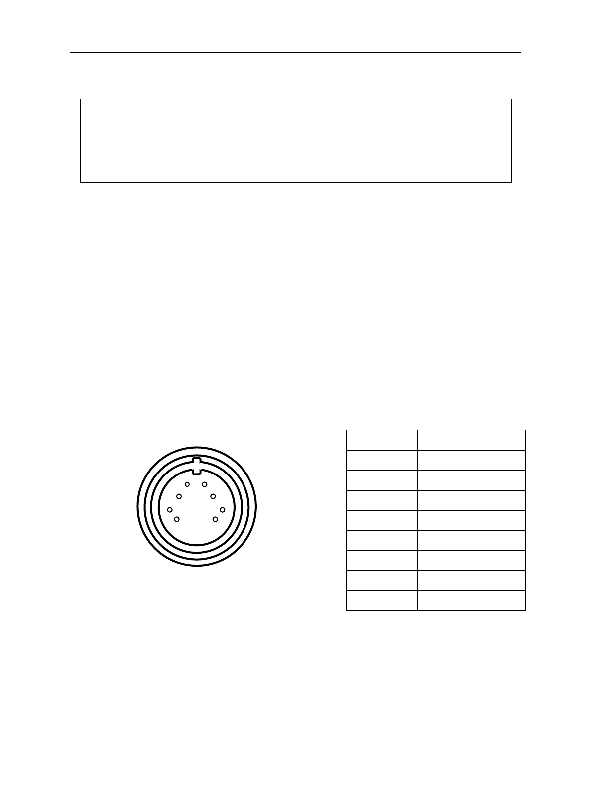
1107200 Shadow VI User Manual
Shadow VI Optic Head Connector
CAUTION
MAKING OR BREAKING CONNECTIONS WITH POWER ON
Power down Shadow before connection or disconnecting any connections at the control,
transmitter or receiver.
Failure to comply with these instructions could result in property damage.
If you discovered in your troubleshooting that the transmitter had no power or was not
functioning properly, we had suggested in the troubleshooting guides that you check the
transmitter wiring to see if it was inadvertently reversed.
If you cannot trace the cables, we suggest that you unplug all the connectors at the optic head
connection. Next, disconnect all the head connectors inside the control except one. Power up
Shadow. Next check pin #4 at the optic head connectors for 12 VDC (see the illustration
below) until you find the right connector.
Be sure that you carefully label the wiring in the control. For 1 set of light curtains, you need
only perform this process once in order to differentiate between transmitter and receiver
wiring. For 2 sets, you must repeat this procedure 3 times. Do this by disconnecting the
connector inside the control that you just identified and plug in another unlabeled connector.
Check which optic head connector pin #4 has 12 VDC. You will be repeating this process
until you have carefully identified all the connectors.
Plug Pin # Cable Wire Color
1 Shield
8
7
6
5
1
2
3
4
2 Black
3 Brown
4 Red
5 Orange
6 Yellow
7 Green
8 Blue
Figure 4-1. Optic Head Connector Pinout Orientation and Chart
page 86 Chapter 4 Troubleshooting Shadow VI
Page 99

Shadow VI User Manual 1107200
Checking and Cleaning Lens Window(s)
Sometimes dirt, oil, or another substance can get on the plastic lens window on each optic
head, which could block a light beam and prevent press operation. This might be the case
when the red light is on at the control and receiver with no objects in the light field.
If your operation is particularly dusty, oily, or smoky, general build-up of dirt could also
affect operation. Both problems are easily corrected by cleaning the lens window with a
clean, particle-free cloth. Use a mild solution of detergent and water, a solvent (such as
acetone), or an isopropyl-based cleanser. Make sure you avoid excessive rubbing.
Checking Alignment
Shadows can go out of alignment if the universal mounting brackets have been bent, if a unit
has been hit (by a die cart or forklift, for example), or if mounting bolts have loosened,
allowing the units to move slightly. You may have an alignment problem if the red indicator
light stays on even with the light field clear.
To check alignment, first loosen one optic head's universal mounting brackets at both ends.
Then, rotate the head back and forth to see if this generates a green light. See "Aligning and
tightening down your Shadows" in Chapter 2 for alignment procedures.
If that does not solve the problem, remove either the receiver or transmitter (whichever is
easier) from its bracket, and move it right up to the other unit —within 6 to 11" (15.2 to 27.9
cm). Make sure that the connection to the control remains intact as you move it closer.
Aim that unit so it is pointing directly at the mating optic head exactly in a straight line. See
the alignment information and diagrams in Chapter 2 if you are not sure what this means.
Shadows will always align at this close range if working properly.
Alignment Problem or Bad Phototransistor
Observe the lights at the receiver and the control as you test Shadow. If the green light
comes on at close range, alignment may be the problem. However, you have to make one
more check to be sure. Place both units on a bench so that they are aligned and the green
light is on. Now start moving one unit away from the other, making sure you keep the beams
aligned.
If you find the red lights come on at further distances, but the green lights come on at close
range, the problem may be a bad phototransistor or LED. Phototransistors are the devices
inside the receiver that detect the light beams. When one becomes weak, it can detect a light
beam close up, but not at greater distances. LEDs send the light from the transmitter to the
phototransistors at the receiver. If they are weak, they cannot generate enough light at greater
distances. If you suspect a bad LED or phototransistor, contact Wintriss Tech Support
immediately to discuss return of the unit.
If the green lights stay on even as you move the units apart, then your mounting on the machinery is the problem. A unit may have been hit and moved out of alignment or a bracket
may have been bent, shifting the unit out of alignment. Check for the cause of misalignment
and correct it. See Chapter 2 for proper alignment procedures.
Troubleshooting Shadow VI Chapter 4 page 87
Page 100

1107200 Shadow VI User Manual
Checking and Replacing Fuses
!
WARNING
ELECTRIC SHOCK HAZARD
• Ensure that the power source is off before checking or replacing fuses.
• Disconnect power from the machinery it is connected to before making any wiring
connections. This includes disconnecting power to the machine control and motor.
• Ensure that all procedures are performed by qualified personnel.
Failure to comply with these instructions could result in death or serious injury.
Any time Shadow loses power or will not allow press operation, first check the fuses that are
located in the control. They are easy to check and replace.
The fuses are common 3AG glass cartridge fuses (1/4" dia. x 11/4" length) listed in Appendix
D. The rating, 1/4 amp and 4 amp, is marked next to the fuse on the circuit board. Here is
how to check the fuses inside the control.
1. Turn off power to Shadow. Never check or change fuses with the power on.
2. Open the hinged cover of the control by loosening the locking screws.
3. Locate the fuses on the circuit board. Refer to the location of components illustration in
Chapter 2. There are 4 fuses - 1 power (at F1), 2 stop (at location F2 and F3), and 1
status (at F4).
4. Remove the plastic cover over the fuse. Look to see if the metallic strip inside any of the
fuses is broken. Test with an ohmmeter if available. Put the ohmmeter leads on each side
of the fuse. No resistance (0 ohms) means the fuse is good.
5. If the fuse has blown, pop it out of the holder by prying it out at the ends. Snap in a new
fuse.
6. Replace all plastic fuse covers.
!
WARNING
ELECTRIC SHOCK HAZARD
Replace plastic fuse covers after checking or replacing fuses. These covers help reduce the
risk of electric shock.
Failure to comply with these instructions could result in death or serious injury.
7. Close the control. Insert and tighten the locking screws.
page 88 Chapter 4 Troubleshooting Shadow VI
 Loading...