

Page 1
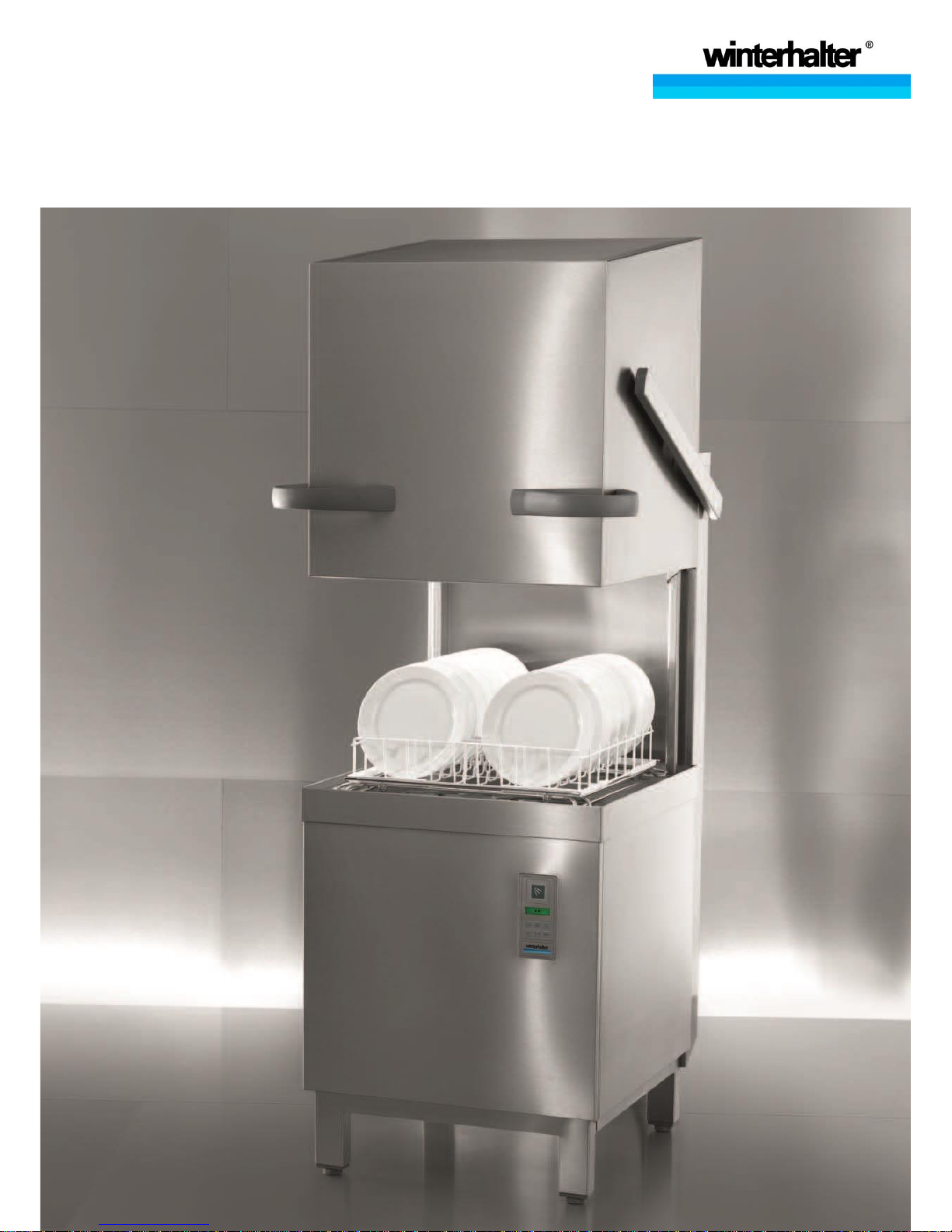
Rack pass-through dishwasher
PT-500
Operating instructions
Page 2

Page 3

About this manual
1
Operating instructions
for Winterhalter PT-500 rack pass-through dishwasher
(translation of the original German operating instructions)
Table of contents
1 About this manual -------------------------------- 2
2 Safety notes ---------------------------------------- 2
2.1 Proper use ------------------------------------------- 2
2.2 Improper use ---------------------------------------- 2
2.3 Electrical Safety ------------------------------------ 3
2.4 Safety Instructions for Maintenance and
Repairs ----------------------------------------------- 3
2.5 General safety notes ------------------------------ 3
3 Before working with the machine ----------- 3
4 Product description ------------------------------ 4
4.1 Mode of operation ---------------------------------- 4
4.2 Overview --------------------------------------------- 4
4.3 Operating panel and washing programmes - 5
5 Rinse aid and detergent ------------------------ 5
5.1 Rinse aid --------------------------------------------- 5
5.2 Detergent --------------------------------------------- 6
5.3 Suction tube with level control ------------------ 6
5.4 Changing the detergent product ---------------- 7
5.5 Priming the dosing devices ---------------------- 7
6 Integral water softener (special
equipment) ------------------------------------------ 7
6.1 Lack of salt display--------------------------------- 7
6.2 Filling regeneration salt --------------------------- 8
7 Operation -------------------------------------------- 8
7.1 Before switching on the machine --------------- 8
7.2 Switching on the machine and preparing it
for operation ----------------------------------------- 8
7.3 Washing ---------------------------------------------- 9
7.4 Switching off ---------------------------------------- 10
8 Servicing and maintenance ------------------ 10
8.1 Daily cleaning -------------------------------------- 10
8.2 Weekly cleaning ----------------------------------- 12
8.3 Monthly cleaning ---------------------------------- 12
8.4 Maintenance by the Customer Service ------ 12
9 Malfunctions -------------------------------------- 13
9.1 Poor cleaning result ------------------------------ 14
10 Info Level ------------------------------------------- 15
11 Error memory ------------------------------------- 15
12 PIN Menu ------------------------------------------- 16
13 Installing the machine and tables ---------- 19
13.1 Installing the machine ---------------------------- 19
13.2 Building tables ------------------------------------- 19
13.3 Rack guide conversion --------------------------- 19
14 Water connection -------------------------------- 20
14.1 Requirements for the on-site inlet water
connection ------------------------------------------ 20
14.2 Requirements for the on-site water stop cock20
14.3 Connecting the supply hose -------------------- 20
14.4 Connecting the drain hose ---------------------- 20
15 Electrical connection --------------------------- 21
15.1 Connecting the mains cable -------------------- 21
15.2 Establishing an earth connection -------------- 21
15.3 Connection diagram ------------------------------ 22
16 External dosing devices ----------------------- 23
16.1 Terminals -------------------------------------------- 23
16.2 Electrical connection ----------------------------- 24
16.3 Changing the settings ---------------------------- 25
17 Taking the machine out of service for a
long period ---------------------------------------- 25
18 Putting the machine back into service
after a long period of disuse ----------------- 25
19 Technical data ------------------------------------ 26
20 Emissions ------------------------------------------ 26
21 Disposal -------------------------------------------- 26
Page 4
About this manual
2
1 About this manual
This manual contains information and instructions for the safe operation and maintenance of your dishwasher.
Please note carefully the safety notes listed here.
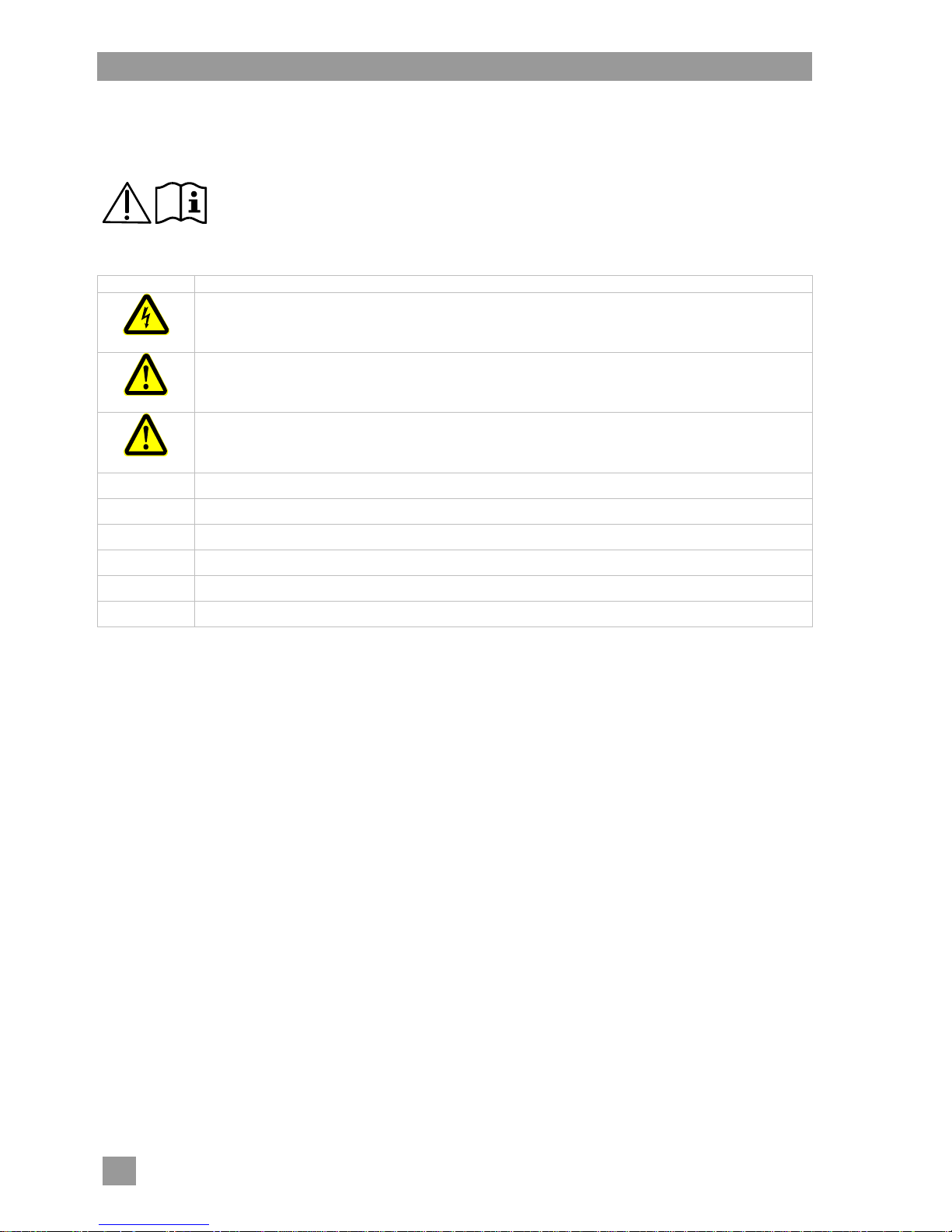
The following symbols are used in these instructions:
Symbol
Meaning
Danger
Warning against potential serious or fatal injuries to persons if the described precautionary
measures are not taken.
Warning
Warning against potential minor injuries to persons or potential material damage if the described precautionary measures are not taken.
Caution
Warning against defects in or destruction of the product if the described precautionary
measures are not taken.
IMPORTANT
Important information is given here.
INFO
Useful information is given here.
This symbol indicates instructions.
This symbol indicates results of your actions.
This symbol indicates itemizations.
This symbol refers to a chapter with more detailed information.
2 Safety notes
2.1 Proper use
The PT-500 dishwasher is a technical device for commercial use and is not intended for private
use.
Use the dishwasher only for the washing of dishes such as plates, cups, cutlery and trays or for
washing glasses of a gastronomic and related type.
2.2 Improper use
This device may be used by children from the age of 8 upwards as well as by those with re-
duced physical, sensory or mental capabilities or a lack of experience and knowledge if they are
supervised or have been instructed on how to safely use the device and understand the risks
associated with it.
Children must not play with the device.
Cleaning and user maintenance should not be carried by children without supervision.
Do not use the dishwasher to wash electrically heated devices or parts made of wood.
Do not wash without a washing rack.
Do not wash parts made of plastic if they are not heat and lye-resistant.
Use a suitable detergent to wash parts made of aluminium such as jars, containers or plates in
order to prevent black stains.
Winterhalter Gastronom GmbH does not assume liability for any damage caused due to im-
proper use of the device.
Page 5

Before working with the machine
3
2.3 Electrical Safety
The electrical safety of this machine is guaranteed only if it is connected to a correctly installed
protective circuit and a residual current circuit breaker. It is very important that this basic safety
requirement is tested and in case of doubt the house installation is checked by a qualified electrician.
Winterhalter cannot be held responsible for damage caused by a missing or broken earthing
system (e.g. electrical shock).
2.4 Safety Instructions for Maintenance and Repairs
Maintenance work and repairs may only be performed by authorized professionals. Improper
maintenance or repairs may cause significant danger for the user, for which Winterhalter is not
liable.
When performing maintenance and repair work, unplug the machine from the power network.
Electricity consumers (heating element) are under voltage until the on-site mains disconnect
switch has been operated.
Only original Winterhalter spare parts may be used for maintenance and repairs. If original
spare parts are not used, the warranty is invalidated.
A damaged or leaking machine can endanger your safety. In case of defects, switch off the ma-
chine immediately. Switch off the local mains separator (main switch). Only then is the machine
without power.
Do not operate a damaged machine. In case of defects resulting from an unknown cause,
switch off the machine and do not switch it on until the defect has been rectified.
Contact your installer or electrician if the on-site water or electricity supply is the cause of the
malfunction.
Notify an authorized service technician or your retailer if another fault has occurred.
If the mains cable of this device is damaged, it must be replaced by the Winterhalter or its Cus-
tomer Service or another qualified person in order to prevent hazards. The mains cable must be
H07 RN-F type or equivalent.
2.5 General safety notes
Read through the safety notes and operating instructions in this manual carefully. Retain the
operating instructions for future reference. Winterhalter Gastronom GmbH does not assume liability or warranty in case of non-adherence to these safety and operating instructions.
Use the dishwasher only after you have read and understood the operating manual. Allow the
Winterhalter Customer Service Department to provide information about the operation and functioning of the dish washer. Always operate the machine as described in these operating instructions.
Train the operating personnel as regards handling the machine and inform them about the safe-
ty notes. Repeat the training sessions at regular intervals to prevent accidents.
For your safety, test the local fault current circuit breaker (FI) regularly by pressing the test but-
ton.
Close the on-site water stop cock after the work is complete.
Switch off the local mains disconnector after the work is complete.
3 Before working with the machine
Have the machine set up by an authorized service technician or your dealer ( 13).
Have the machine connected as per the locally applicable standards and the regulations by authorised
mechanics (water, waste water, electrical system) ( 14 and 15).
After connecting the water and the power properly, contact the relevant Winterhalter dealer or your dealer
for the commissioning of the machine and for providing training in its operation. Get yourself and your operating personnel trained in the operation of the machine.
Page 6
Product description
4
4 Product description
4.1 Mode of operation
The boiler and the tank fill and are warmed up to the operating temperature after the machine is switched on.
The display lights up in red during the warm-up phase. When the target temperatures are reached, the machine is ready for use. The display is lit in green.
The machine is fully automatic with programmes consisting of three steps: Wash, Drain and Rinse. Whilst a
washing programme is running, the display is lit in blue.
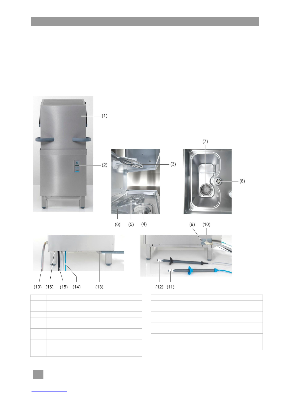
4.2 Overview
Pos.
Description
(1)
Machine hood (= hood)
(2)
Operating panel
(3)
Upper rotating wash field
(4)
Filter basket
(5)
Lower rotating wash field
(6)
Strainer
(7)
Pump inlet filter
(8)
Wash field bearing
(9)
Bushings for cables and hoses
(10)
Water supply hose
Pos.
Description
(11)
Suction tube for rinse aid
(blue cap and blue suction hose)
(12)
Suction tube for detergent
(black cap and transparent suction hose)
(13)
Water drain hose
(14)
Hoses and cable for the suction tubes
(15)
Mains cable
(16)
Connection for local equipotential bonding
system
Page 7
Rinse aid and detergent
5
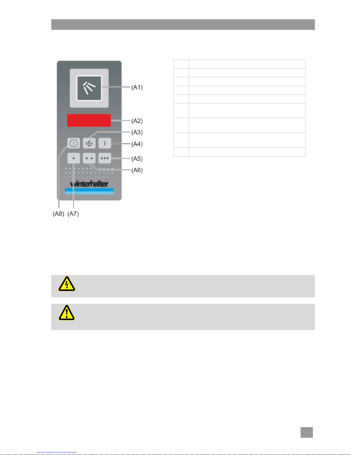
4.3 Operating panel and washing programmes
Pos.
Description
(A1)
Start button
(A2)
Display
(A3)
Self-cleaning programme
(A4)
Info button
(A5)
Intensive programme
(for heavily soiled dishes)
(A6)
Normal programme
(for medium soiled dishes)
(A7)
Short programme
(for lightly soiled dishes)
(A8)
On/Off button
The normal programme (A6) is pre-selected as soon as the machine is ready. In the display (A2) the symbol
for the washing programme appears.
Another washing programme is selected by pressing button (A5) or (A7).
5 Rinse aid and detergent
Danger
When handling chemicals, observe the safety precautions and the dosage recommendations
on the packaging.
Wear protective clothing, protective gloves and protective goggles when handling chemicals.
Caution
Use only products that are suitable for commercial dishwashers. Such products are appro-
priately marked. We recommend Winterhalter products. These are especially adapted to
Winterhalter dishwashers.
Do not put rinse aids in the storage container for detergents and vice versa.
5.1 Rinse aid
A rinse aid is necessary to ensure that water on the dishes drains off after washing and dries off after a short
while. Rinse aid is automatically dosed from an external container. The rinse aid dosing device is an integral
component of the machine. The service engineer authorised by Winterhalter sets the dosing level when
commissioning the machine ( 12).
Page 8
Rinse aid and detergent
6
5.2 Detergent
Caution
Do not use acidic detergents.
Do not mix different detergent products in order to prevent crystallisation which could de-
stroy the detergent dosing device ( 5.4).
Do not use products that can create foam, e.g. hand soap, soft soap, hand wash liquid. En-
sure that these do not enter the machine even during the pre-treatment of the dishes.
A detergent is necessary to ensure that the leftovers and dirt on the dishes is cleaned. Detergents can be
supplied as follows:
Manually as detergent powder.
Automatically from an external container using a detergent dosing device.
INFO The detergent dosing device is not included in the scope of delivery of all machines. When using
an external dosing device, a transfer strip is available for connecting the dosing device ( 16).
5.2.1 Manual dosing of detergent powder
Pre-dosing
Switch on the machine and wait until the display is lit green.
Adhere to the dosing instructions on the packaging of the detergent. The machine's tank capacity is ap-
prox. 35 litres.
Place approx. 100 g of detergent powder in the machine. This corresponds to a dosing of approx. 3 g/l.
Then start the wash cycle immediately to mix the detergent powder with the water.
Post-dosing
At each wash cycle approx. 2.5 litres of fresh water enter the dishwasher, which must be mixed with detergent powder.
Fill approx. 40 g of detergent powder in the machine after 5 wash cycles.
5.2.2 Automatic dosing of liquid detergent
The authorised service technician sets the dosing amount when commissioning the machine ( 12).
5.3 Suction tube with level control
Caution
Only use the suction tube with sufficiently stable containers. Narrow and tall containers can
tip if the suction tube is pulled.
Do not place the suction tube for the rinse aid in the detergent container or vice versa.
Do not pull unnecessarily on the suction hose or main power cable, as this may lead to a
defect.
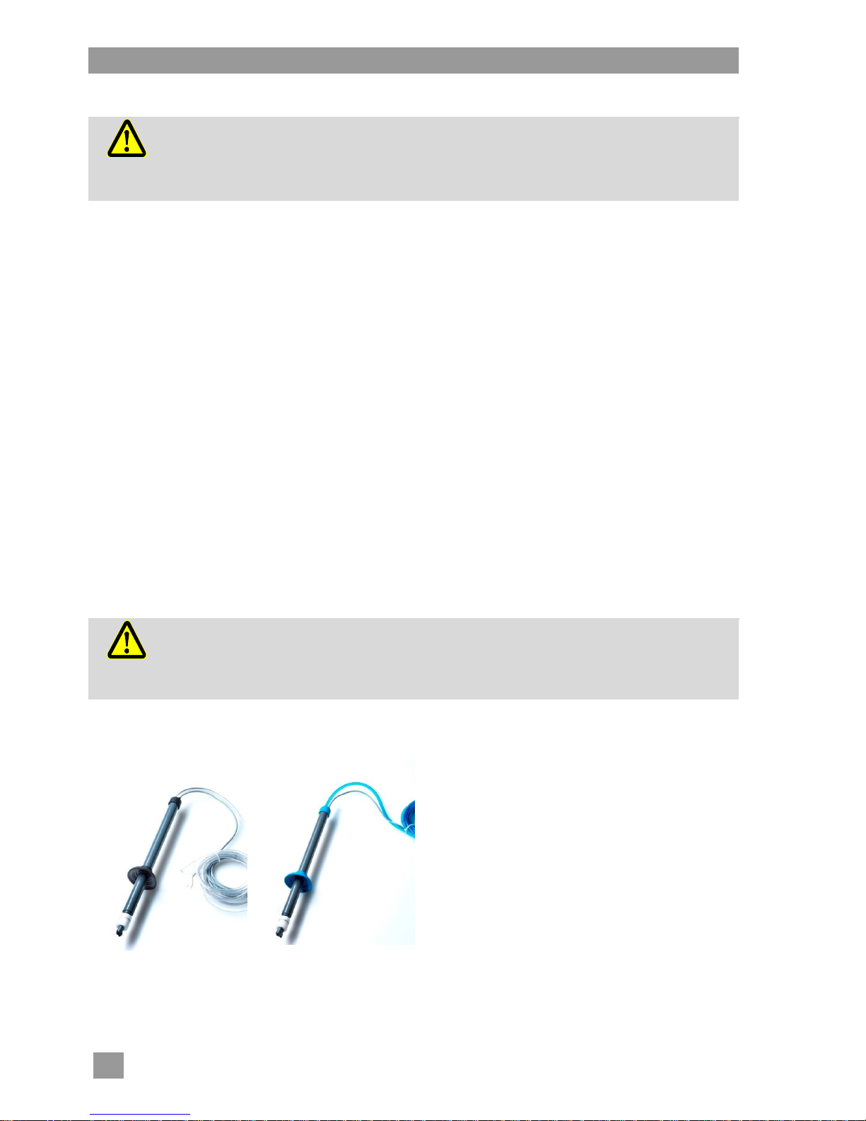
As an option, with your machine you may have one or more suction tubes. The suction tube is already connected to the machine.
Figure 1:
Suction tube for detergent
Transparent suction hose
Black cap
Figure 2:
Suction tube for rinse aid
Blue suction hose
Blue cap
Figure 1
Figure 2
Page 9
Integral water softener (special equipment)
7
Servicing and maintenance
Rinse the suction tube at every container change under running water. Re-
move crystallised detergent residue.
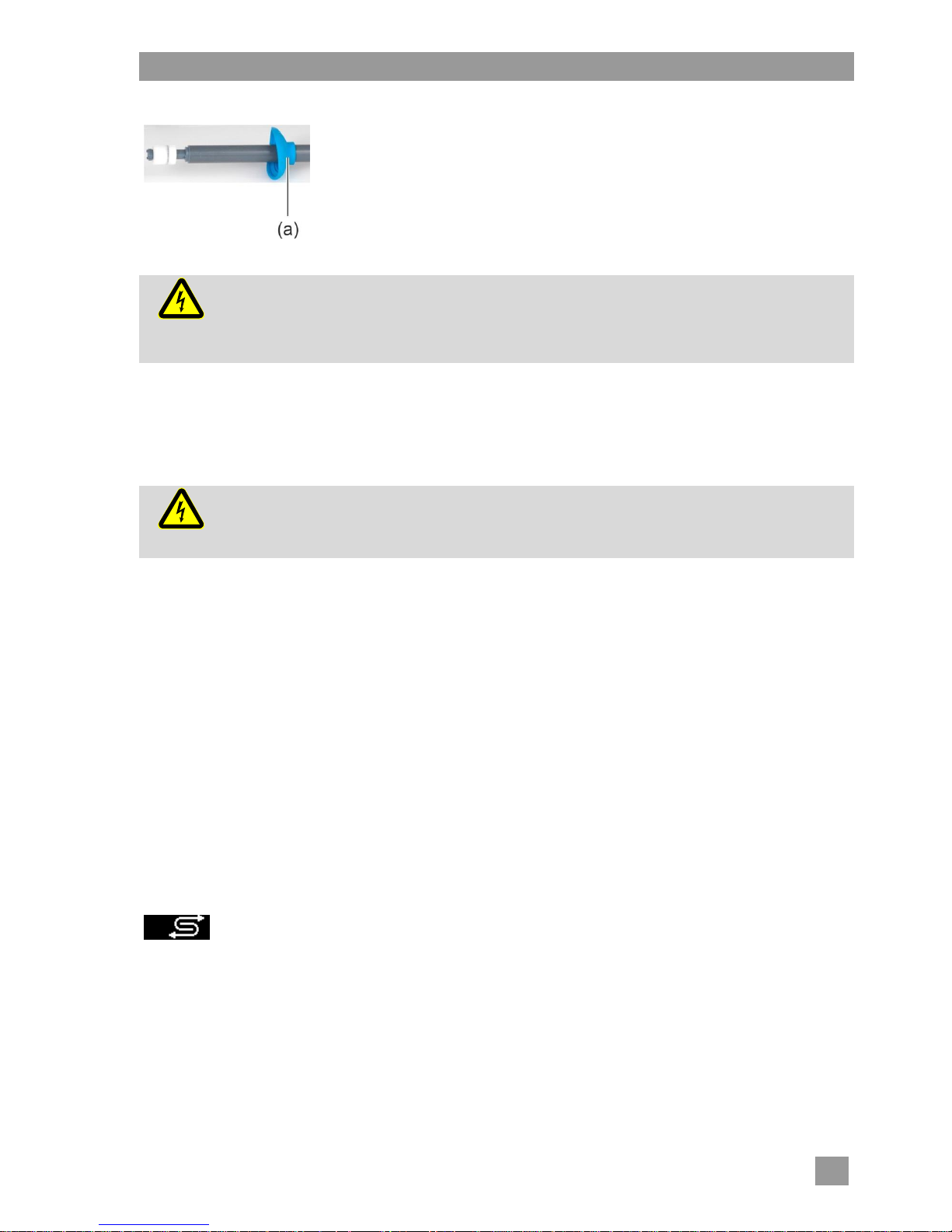
Ensure that both vent holes (a) in the caps are open.
Put the suction tube back into the container. Slide the cap downwards until
the container opening is closed.
5.4 Changing the detergent product
Danger
Mixing different detergents can lead to efflorescence that can lead to a failure of the deter-
gent dosing device. This is applicable even if the new detergent is from the same manufacturer.
The dosing tubes and the detergent dosing device must be thoroughly rinsed with water
before the new detergent is used.
A new detergent product usually requires a new setting of the detergent dosing device. Assign the re-
quired work to a service engineer authorised by Winterhalter to attain good results.
If this is not done, the warranty and product liability of Winterhalter Gastronom GmbH expires.
Procedure:
Danger
Observe the safety precautions when handling chemicals and the dosage recommendations
on the packaging.
Wear protective clothing, protective gloves and protective goggles when handling chemicals.
Do not mix different detergents.
Remove the suction tube from the container and place it in a water-filled container.
Rinse the dosing tube and the detergent dosing device with water. To do this, use the "prime dosing de-
vice" function several times ( 12). The frequency depends on the length of the dosing tubes.
Place the suction tube in the new detergent container.
Use the "prime dosing device" function several times ( 12), to replace the water in the dosing tubes with
detergent.
5.5 Priming the dosing devices
Dosing devices must be primed when air is reached in the dosing tubes because the containers were not
exchanged or refilled in time ( 12).
6 Integral water softener (special equipment)
By softening the inlet water, limescale build-up in the machine and on the dishes is avoided. For the integral
water softener to work correctly, the salt container must be filled with regeneration salt.
INFO At the commissioning of the machine the authorized service technician measures the water hard-
ness and saves it in the machine's electronic control unit.
6.1 Lack of salt display
A pictogram appears in the display screen when an empty salt container requires refilling.
The display disappears after filling the salt container, as soon as approx. 3 wash cycles
have been completed and part of the salt has been dissolved.
Page 10
Operation
8
6.2 Filling regeneration salt
Caution
Possible risk of damage to the water softener
Chemicals such as detergent and rinse aid inevitably lead to damage to the water softener.
Fill only with regeneration salt or pure evaporated salt.
Possible malfunction of the water softener
Do not fill with other salts (e.g table salt cleaning or de-icing salt). These can contain water-
insoluble components. Fill only with fine-grained salt (max. 0.4 - 7 mm grain size).
INFO Salt tablets are not suitable.
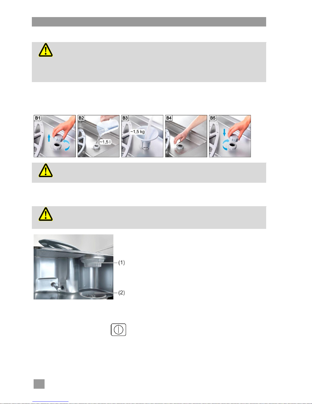
Proceed in accordance with Figures B1 to B5.
IMPORTANT Figure B2 is only relevant for the first filling.
Caution
Risk of rust formation in the filling area
Immediately after filling, start a wash cycle to rinse off any salt residue.
7 Operation
7.1 Before switching on the machine
Caution
Possible risk of damage due to suction of items from within the machine e.g. pieces of
cutlery
The pump inlet filter protects the circulating pump and the drain pump. Operate the machine
only with the pump inlet filter fitted.
Open the on-site water stop cock.
Switch on the local mains disconnector.
For your own safety, test the on-site residual-current circuit
breaker (FI).
Open the hood.
Remove the filter basket (1).
Check whether the pump inlet filter (2) is fitted.
Put the filter basket (1) back in.
Check whether the rotating wash fields (top and bottom)
are fitted and properly engaged.
Close the hood.
Check whether sufficient detergent and rinse aid are pre-
sent in the storage containers. Replace the storage containers in time so that the cleaning results are not affected.
7.2 Switching on the machine and preparing it for operation
Press the On/Off button.
The display is lit in red.
As soon as the machine is ready for operation, the display is lit in green.
Page 11
Operation
9
7.3 Washing
Warning
Possible risk of scalding from hot wash water
Keep children away from the dishwasher. The wash water is at a temperature of approx.
62 °C.
Do not open the hood while the machine is washing. There is a risk of the hot wash water
spilling out. Stop the washing programme before doing so ( 7.3.6).
Possible risk of injury
During operation the hood becomes hot. Therefore, only grasp the hood by the handles.
Arrange sharp, pointed utensils so that they do not cause injury.
Caution
Possible failure of the washing programme due to heavy dirt ingress
Pre-rinse all dishes and pans with cold water. Remove food residues.
7.3.1 Arranging the dishes in the washing rack
Dishes and cutlery
Place plates with their upper surface facing forwards.
Place cups, bowls and pots rim down.
Wash cutlery either standing in the cutlery holder or lying in a shallow basket. Make sure that they are not
too close together. Soak cutlery, before you wash it.
Position knives and other sharp objects in the cutlery holder with the handle up in order to prevent inju-
ries.
Glasses
Pour out drink residue (not in the machine).
Remove scraps of paper.
Rinse off ash with water.
Place glasses rim down.
Space glasses, so they do not rub against each other. This will avoid scratches.
For tall glasses choose a basket with appropriate divisions so that the glasses are held in a stable
position.
7.3.2 Using automatic hood start
Choose a washing programme ( 4.3).
The washing programme remains selected until a different washing programme is chosen.
Slide the washing rack into the machine.
Check that the top and bottom rotary wash arms are free to turn.
Close the hood.
The washing programme is started.
The display is lit in blue.
INFO The automatic hood start can be deactivated by an authorised service technician (P807). Every
washing programme must then be started by pressing the start button.
7.3.3 Interrupting automatic hood start
Do not close the hood completely, but only as far as the lower detent position.
Page 12
Servicing and maintenance
10
7.3.4 Changing washing programme
Select a new washing programme.
The symbol for the washing programme appears in the display.
Close the hood.
The washing programme is started.
7.3.5 End of the programme
The display flashes green, as soon as the washing programme has ended and the hood remains unopened.
7.3.6 Prematurely terminating the washing programme
A washing programme can be terminated in the following ways:
Press the start button
Press the On/Off button.
7.3.7 Periods of disuse
Do not switch the machine off during periods of disuse.
Close the hood as far as the detent position to prevent it cooling down.
7.4 Switching off
Switch the machine off at the end of the working day using the self-cleaning programme ( 8.1.2), so that it
is cleaned and emptied every day.
INFO If you use the On/Off switch, the tank stays filled but will no longer be kept at temperature. If the
tank temperature has dropped too much before the machine is switched on again, the tank will be
emptied automatically and filled again.
8 Servicing and maintenance
Warning
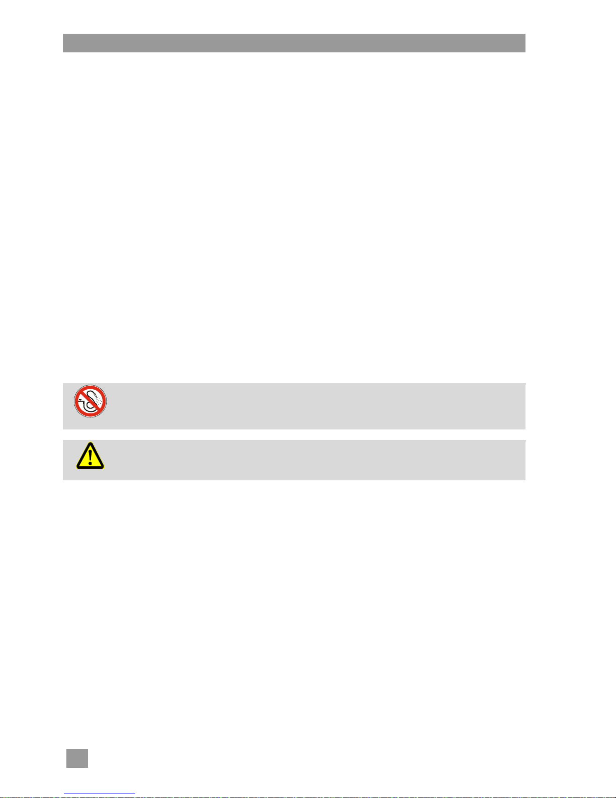
Do not spray the machine and the surrounding area (panels, base) using a water hose,
steam-jet air ejector or high-pressure cleaner.
Ensure that the base of the machine is not flooded when cleaning the floor in order to pre-
vent an uncontrolled inflow of water.
Warning
Wear protective clothing and protective gloves before touching parts in contact with detergent
solution (filters, rotating wash fields, ...)
8.1 Daily cleaning
8.1.1 During operation
Remove the filter basket, clean if necessary and re-insert it.
Page 13
Servicing and maintenance
11
8.1.2 Self-cleaning programme at the end of the working day
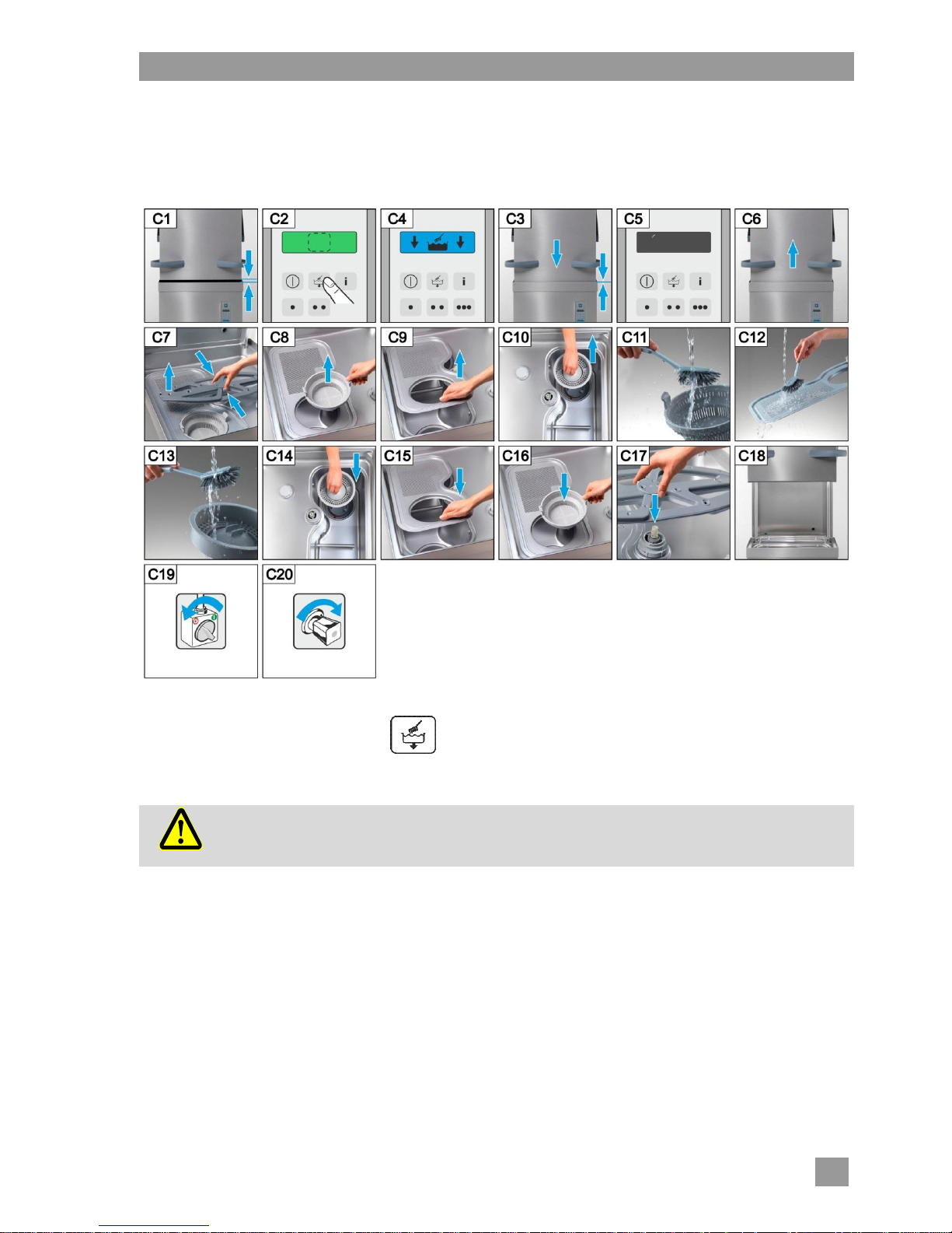
The machine is equipped with a self-cleaning programme that assists you when you are cleaning the inside
of the machine.
Proceed in accordance with Figures C1 to C20.
Terminating the self-cleaning programme
Press this button.
The display is lit in red.
The machine is filled again.
8.1.3 Cleaning the interior
Caution
Ensure that there are no rusty foreign objects in the machine which can cause even "rust-free
stainless steel" material to start rusting. Rust particles can come from non-rust-free cleaners,
damaged wire racks or non-rust-protected water lines.
The following materials must not be used for cleaning:
High-pressure cleaner
Detergents containing chlorine or acid
Cleaning sponge or wire brush containing metal
Abrasives or abrasive cleaners
Remove dirt with a brush or a cloth.
8.1.4 Cleaning the exterior of the machine
Clean the operating panel and display with a damp cloth.
Clean the external surfaces using a stainless steel cleaner and stainless steel polish.
Page 14
Servicing and maintenance
12
8.2 Weekly cleaning
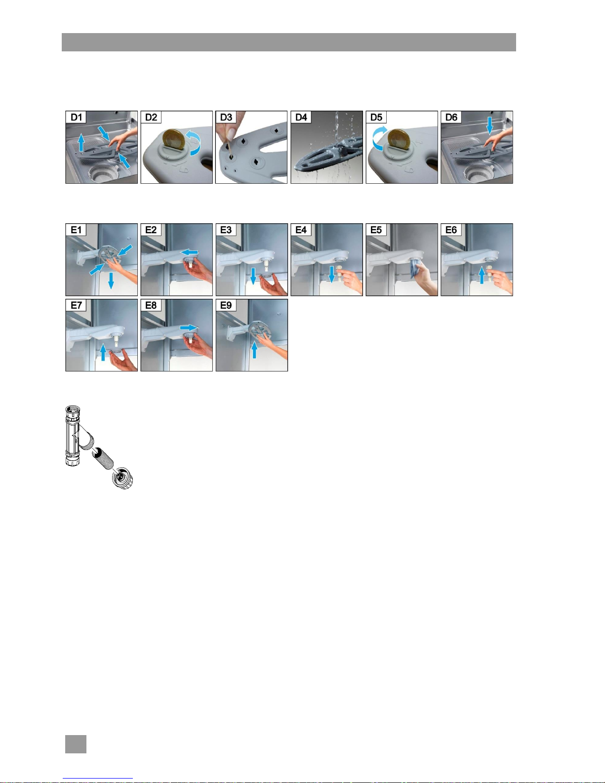
Cleaning the rotating wash fields (top and bottom)
Proceed in accordance with Figures D1 to D6.
Cleaning the wash field bearings (top and bottom)
Proceed in accordance with Figures E1 to E9.
8.3 Monthly cleaning
Cleaning the dirt trap
Close the water stop cock.
Clean the dirt filter in the dirt trap.
8.4 Maintenance by the Customer Service
We recommend that you have an authorised Winterhalter service engineer carry out the maintenance of the
machine at least once a year so that vulnerable parts can be checked and replaced accordingly. Original
spare parts must be used for repairs and the replacement of worn parts.
Worn parts are, for example:
Dosing pipes
Bearings of the rotating wash fields
Water supply hose
Page 15
Malfunctions
13
9 Malfunctions
This chapter explains the remedies for malfunctions. The causes and remedies are specified in the tables.
Contact a Winterhalter service engineer if you cannot rectify the error yourself.
Danger
Danger to life. Live components.
Do not open any machine covers or machine parts if it requires tools. There is danger of
shock.
Only a Winterhalter service engineer should carry out work on the electrical system. The
machine must first be disconnected from the mains.
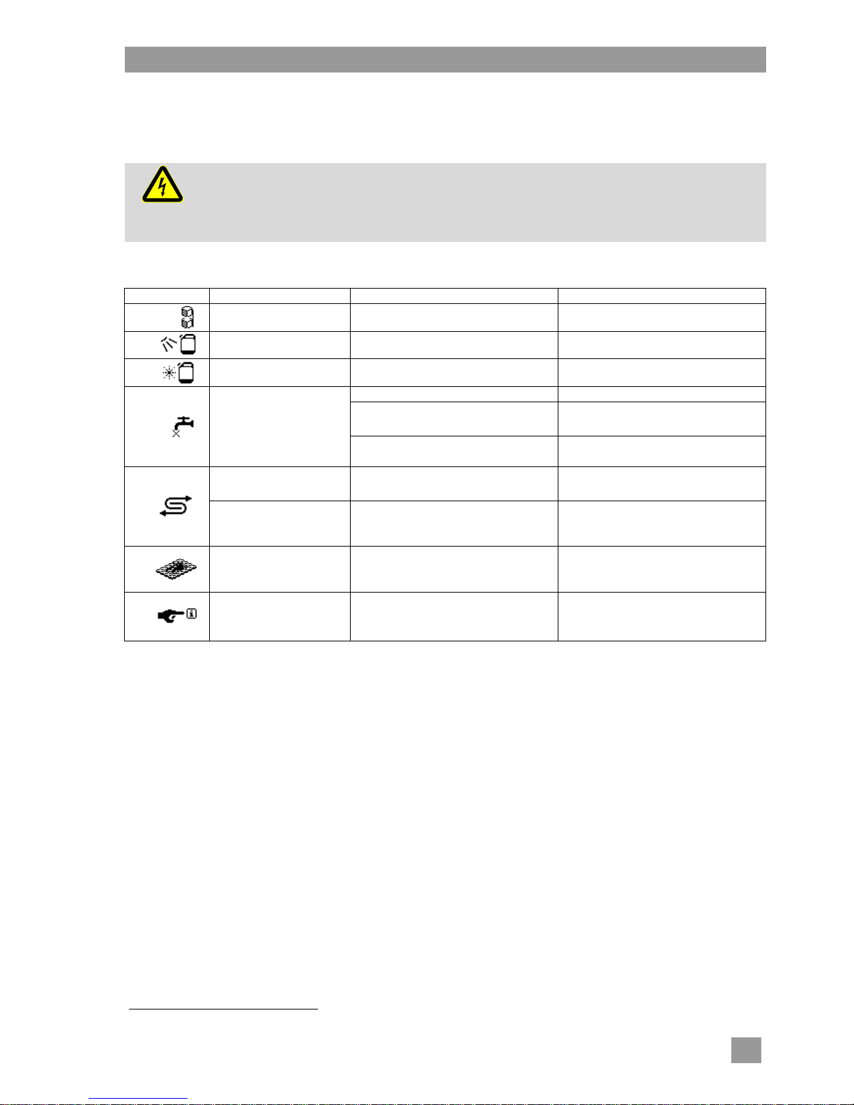
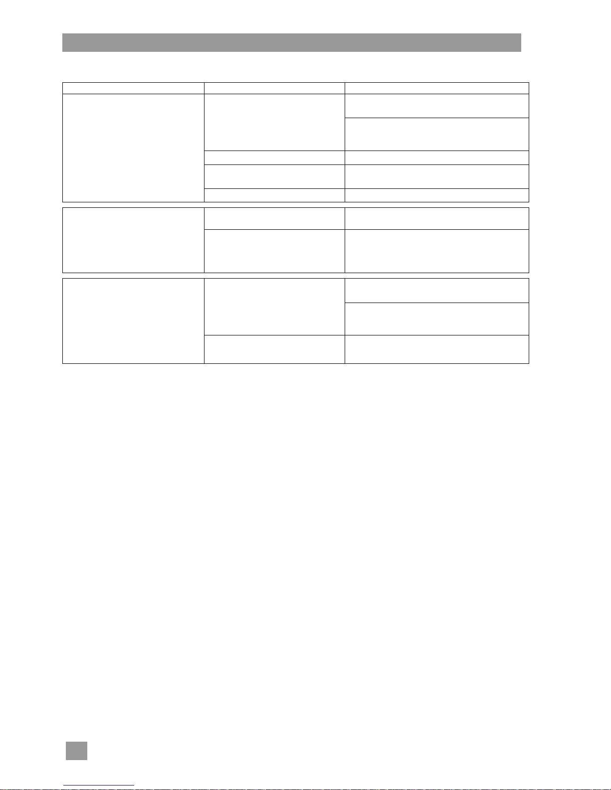
Faults are displayed in the display in the form of pictograms.
Pictogram
Meaning
Possible cause
Remedy
Hood is open
Programme start with open hood
Close the hood
Detergent is empty1
Change the detergent container
Rinse aid is empty1
Change the rinse aid container
Lack of water
Water stop cock closed
Open the water stop cock
Dirt filter in the dirt trap is blocked
Remove and clean the dirt filter
( 8.3)
Solenoid valve defective or
blocked
Contact an authorised service
technician for the repair
Integral water treatment is exhausted
Low salt
Fill the salt reservoir with regenerating salt ( 6.2)
External partial or full
demineralisation unit
blocked
Exchange the partial demineralisation unit; exchange the resin of
the full demineralisation unit
Strainer clogged
Very dirty strainer
Remove the filter basket and
strainer, clean as necessary and
re-insert them.
Malfunction with error
code
Various
Display the error code ( 11) and
assign the repair to an authorised
service technician
1
is only displayed, when a suction tube with level control is used and connected to the machine
Page 16
Malfunctions
14
9.1 Poor cleaning result
Possible cause
Remedy
The dishes do not get clean
No or low detergent dosing
Set the dosing amount as per the manu-
facturer’s specifications ( 12)
Check the dosing lines (for kinks, breakage, ...)
Replace the storage container if empty
Dishes incorrectly sorted
Do not stack dishes one over the other
Nozzles of the rotating wash
fields blocked
Remove the rotating wash fields and clean
the nozzles ( 8.2)
Temperatures too low
Check temperatures ( 10)
There is formation of layers on
the dishes
In case of limescale deposits:
The water is too hard
Check the water treatment
Clean thoroughly
In case of starch residues:
Excessively high temperatures
during manual pre-cleaning
(hand shower)
The temperature of the manual pre-wash
should be a maximum of 30 °C
The dishes do not dry on their
own
No or low rinse aid dosing
Set the dosing amount as per the manu-
facturer’s specifications ( 12)
Check the dosing lines (for kinks, breakage, ...)
Exchange the storage container if empty
Rinse temperature too low
Contact an authorised service technician
for the repair
For machines without integral softener:
INFO The water quality affects the washing and drying performance. We therefore recommend from a
total hardness of more than 3° dH (0.53 mmol/l) that the machine is supplied with softened water.
Page 17
Info Level
15
10 Info Level
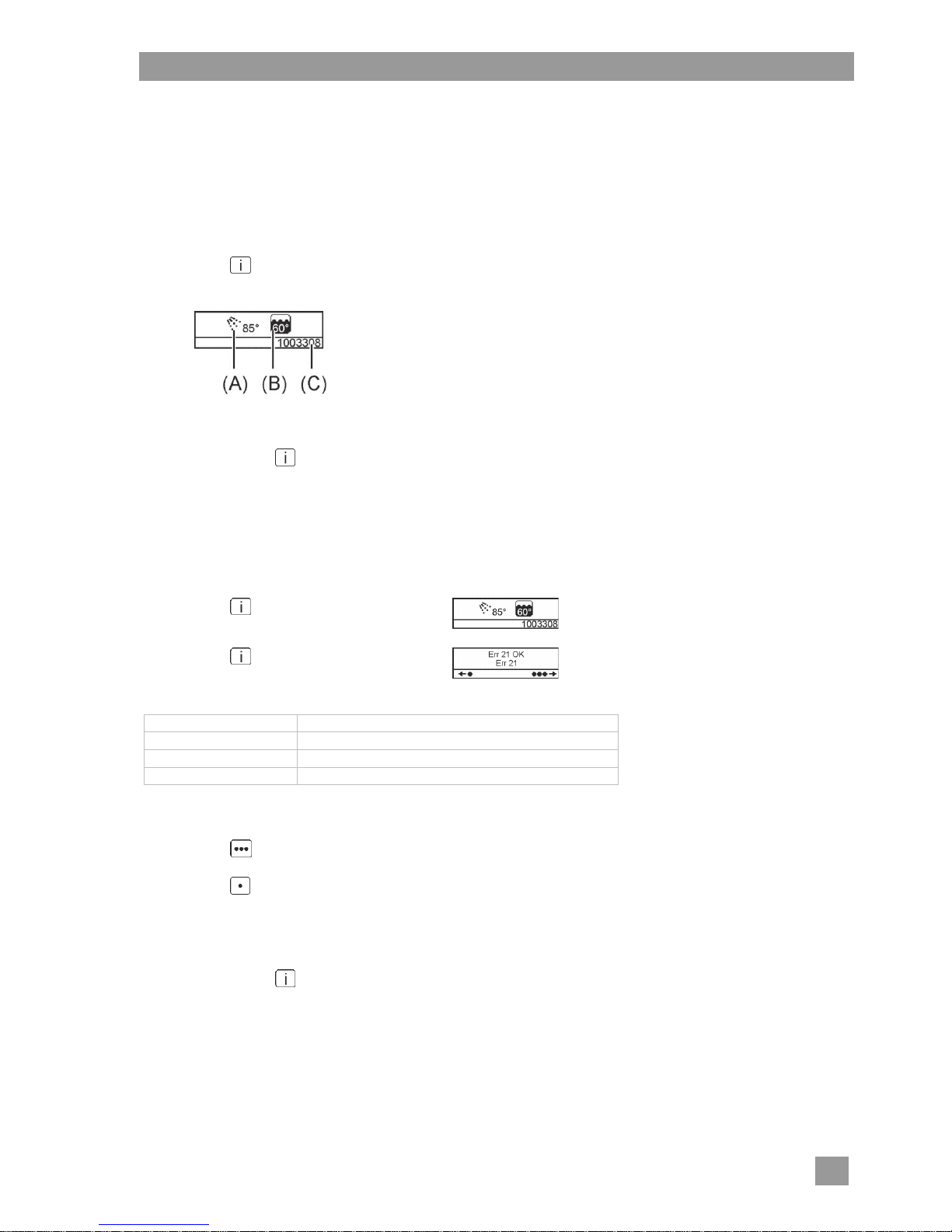
In the Info Level you can retrieve the following information:
Temperature in the boiler
Temperature in the tank
Serial number
Calling Info Level
Press the button.
The following information is shown in the display:
(A)
(B)
(C)
Temperature in the boiler
Temperature in the tank
Serial number
Leaving Info Level
Press the button three times.
11 Error memory
All errors with an error code are saved in the error memory. The error that occurred last is displayed first.
Accessing the error memory
Press the button.
The temperatures are displayed.
Press the button again.
The error memory will be displayed.
Display
Explanation
ERR xx
Malfunction
ERR xx OK
Malfunction resolved
ON ↑
Entry is generated by turning on the machine
Navigating in the error memory
Press the button several times.
Older errors are displayed.
Press the button several times.
Newer errors are displayed.
Leaving the error memory
Press the button twice.
Page 18
PIN Menu
16
12 PIN Menu
You can carry out the following activities in the PIN menu:
Set the dosing of the detergent and rinse aid for each programme
Prime the rinse aid dosing device
Prime the detergent dosing device
Programme the transfer strip for the connection of external dosing devices ( 16.3)
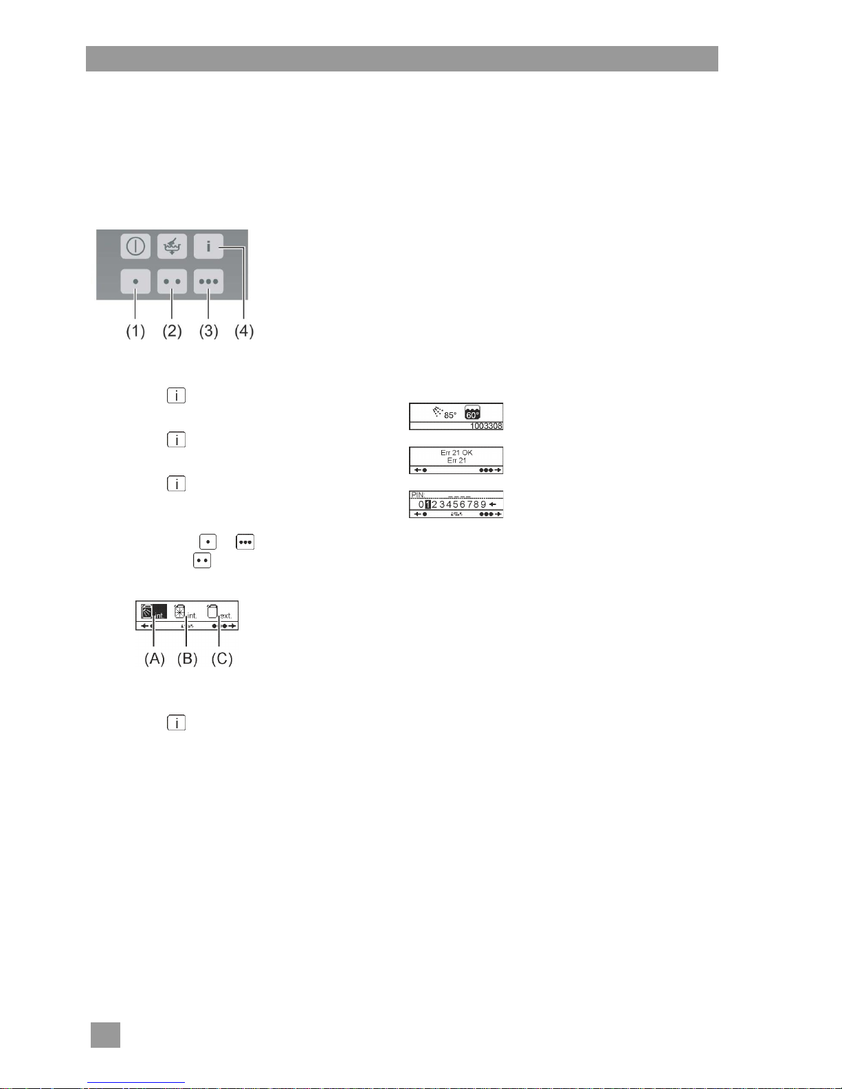
Explanation of the buttons
(1) Cursor left or reduce value
(2) Confirm
(3) Cursor right or increase value
(4) Back
Accessing the PIN Menu
Press the button.
The temperatures are displayed.
Press the button again.
The error memory will be displayed.
Press the button again.
The PIN input mask is displayed.
Enter PIN 1575. To do this, select the individual
figures with the or button and confirm each
figure with the button.
The following selection is shown in the display:
(A) Integral detergent dosing device
(B) Integral rinse aid dosing device
(C) Ext. Dosing
Leaving the PIN Menu
Press the button.
Page 19
PIN Menu
17
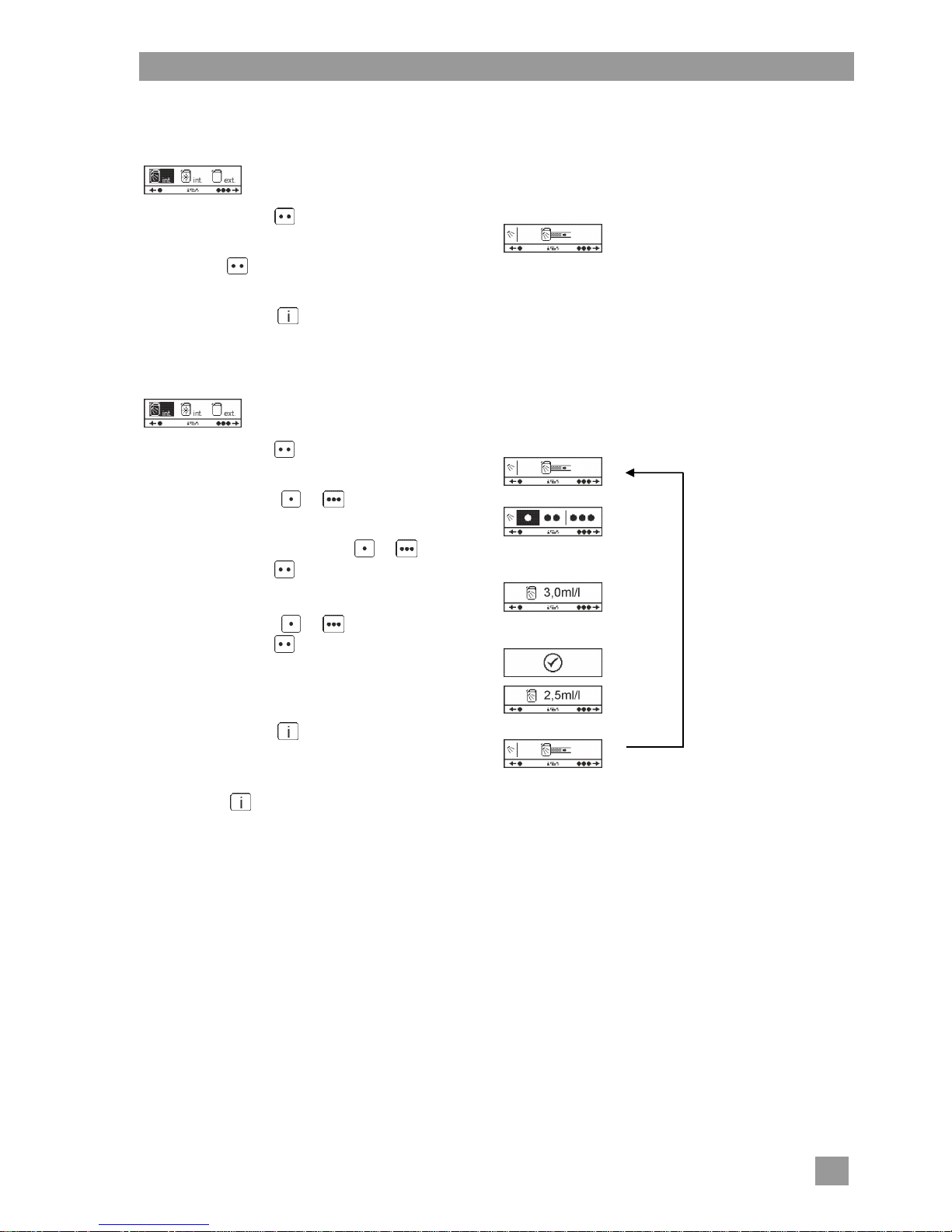
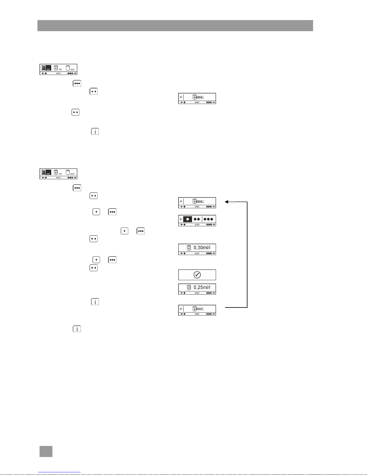
(A) Integral detergent dosing device
Priming the dosing device
= Output screen
Confirm with the button.
The next screen is displayed.
Keep the button pressed.
The dosing device is primed.
Go back with the button.
The output screen is displayed.
Setting the dosing
= Output screen
Confirm with the button.
The next screen is displayed.
Continue with the or button.
The programme is displayed.
Select a programme with the or button.
Confirm with the button.
The current dosing is displayed
(number flashes).
Continue with the or button.
Confirm with the button.
The input is confirmed.
The newly set value is displayed
(number flashes).
Go back with the button.
This screen is refreshed.
Press the button to go back.
The output screen is displayed.
Repeat as necessary
for the other programmes.
Page 20
PIN Menu
18
(B) Integral rinse aid dosing device
Priming the dosing device
= Output screen
Press the button.
Confirm with the button.
The next screen is displayed.
Keep the button pressed.
The dosing device is primed.
Go back with the button.
The output screen is displayed.
Setting the dosing
= Output screen
Press the button.
Confirm with the button.
The next screen is displayed.
Continue with the or button.
The programme is displayed.
Select a programme with the or button.
Confirm with the button.
The current dosing is displayed
(number flashes).
Continue with the or button.
Confirm with the button.
The input is confirmed.
The newly set value is displayed
(number flashes).
Go back with the button.
This screen is refreshed.
Press the button to go back.
The output screen is displayed.
(C) Ext. Dosing ( 16.3)
Repeat as necessary
for the other programmes.
Page 21
Installing the machine and tables
19
13 Installing the machine and tables
The installation site must be frost-resistant so that the water supply systems do not freeze. If the installation
site is not frost-free: 17.
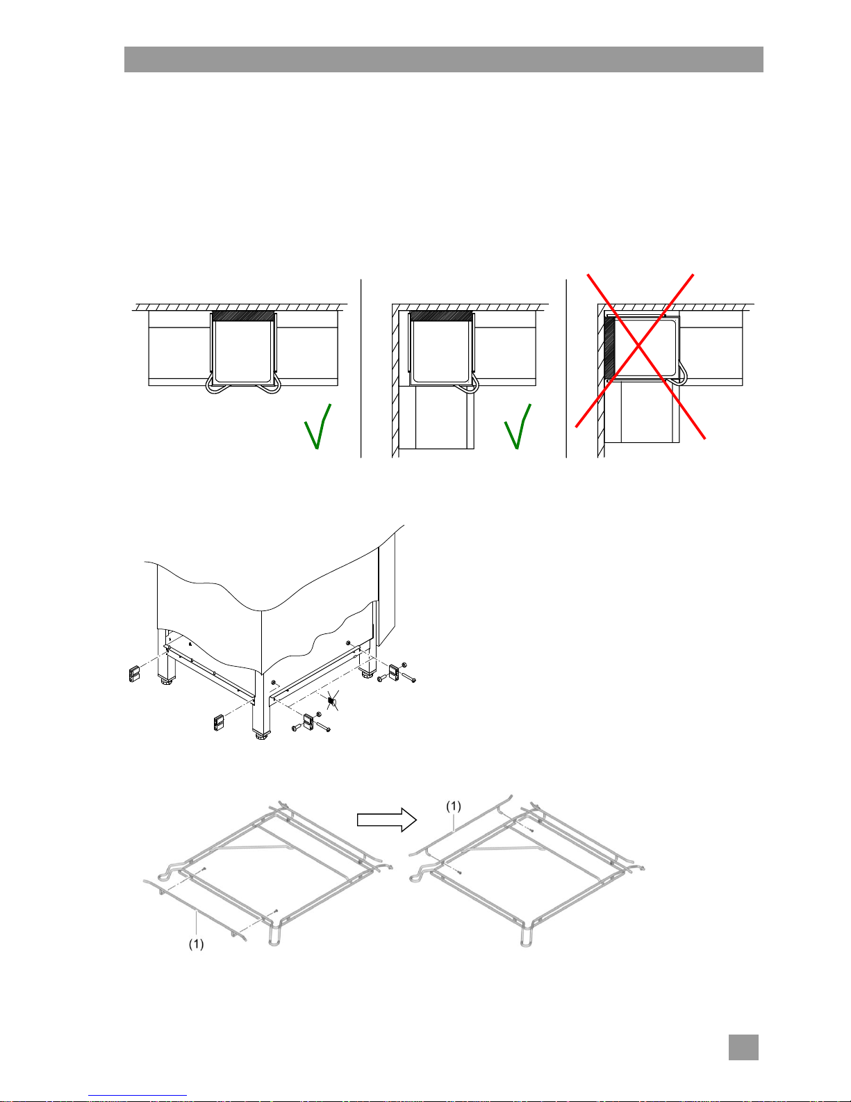
13.1 Installing the machine
INFO No gap is required between the wall and rear of machine.
Install the machine horizontally with the help of spirit level.
Adjust the base unevenness with the help of the height-adjustable machine feet.
Installation variants
INFO If the machine is installed in a corner, the left hood handle must be removed. For plugging holes a
kit with part no. 30002147 is available.
13.2 Building tables
Assemble tables.
When Winterhalter tables are used, attach aluminium
strut supports to the machine.
The aluminium strut supports are in the machine.
Secure the tables to the machine.
Connect the earthing cable from the table to the ma-
chine.
13.3 Rack guide conversion
INFO If the machine is installed in a corner, the rack guide must be converted.
Unscrew the front guide bar (1) and attach to the left side of the rack guide.
Page 22
Water connection
20
With separately available guide bars, the rack guide can be converted to the following rack sizes and wall
distances:
Rack size
Distance between the wall and rear of the rack guide
500 x 500 mm
170 mm
530 x 530 mm
155 mm
500 x 500 mm
140 – 150 mm
600 x 400 mm
170 mm
600 x 400 mm
235 mm
14 Water connection
The water-related safety should be as per DIN EN 61770. The machine can be connected to an inlet water supply without an intermediate connection to other safety equipment.
Warning
The machine and any other relevant additional devices must be connected by an authorised specialist company in
relation to local standards and regulations.
14.1 Requirements for the on-site inlet water connection
Water quality
The inlet water must in microbiological aspects have the quality of drinking water
Water inlet temperature
max. 60 °C (80 °C on demand)
max. 50 °C for "effect" version glass washers
Water hardness
3 °dH (3.8 °e / 5.34 °TH / 0.54 mmol/l ) (recommendation to prevent scaling of the machine)
30 °dH (37.6 °e / 53.4 °TH / 5.35 mmol/l) for machines with an integral softener
Minimum flow pressure
100 kPa (1.0 bar)
Maximum inlet pressure
600 kPa (6.0 bar)
Rate of flow
at least 4 l/min
14.2 Requirements for the on-site water stop cock
easily accessible
not behind the machine
3/4" connector
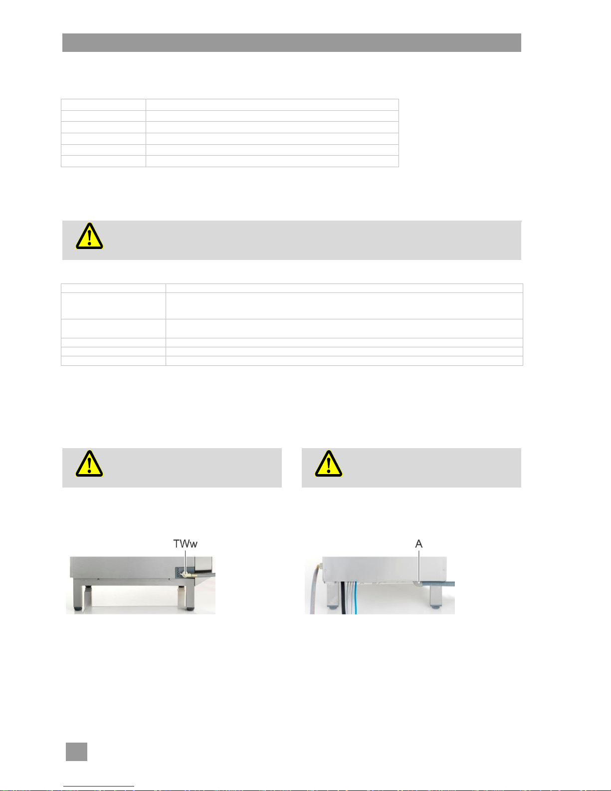
14.3 Connecting the supply hose
Caution
The supply hose may not be shortened or
damaged.
Old existing hoses may not be re-used.
Do not bend the supply hose while laying it.
The supply hose and dirt trap are located in the machine.
INFO The dirt trap prevents particles from the water supply
line entering the machine thus preventing extraneous
rust on the cutlery and in the machine.
Right view
Connect the supply hose (TWw) to the machine.
Connect the dirt trap to the on-site water stop cock.
Connect the supply hose to the dirt trap.
Open the water stop cock and test whether the connections
are tight.
14.4 Connecting the drain hose
Caution
The drain hose may not be shortened or damaged.
Do not bend the drain hose when laying it.
The drain hose is located in the machine.
INFO The machine is equipped with a drain pump. The on-
site water drain must have a trap. The maximum height
of the on-site water drain is 650 mm.
Back view
Connect the drain hose (A) to the machine.
Connect the drain hose to the on-site water drain.
Page 23
Electrical connection
21
15 Electrical connection
Danger
Danger to life. Live components.
The machine and the relevant additional devices must be connected by an electrical company authorised by the
relevant electricity supplier as per the locally applicable standards and regulations.
When performing installation and maintenance work, unplug the machine from the power network. Check that there
is no voltage.
The electrical safety of this machine is guaranteed only if it
is connected to a correctly installed protective circuit and a
residual current circuit breaker. It is very important that this
basic safety requirement is tested and in case of doubt the
house installation is checked by a qualified electrician.
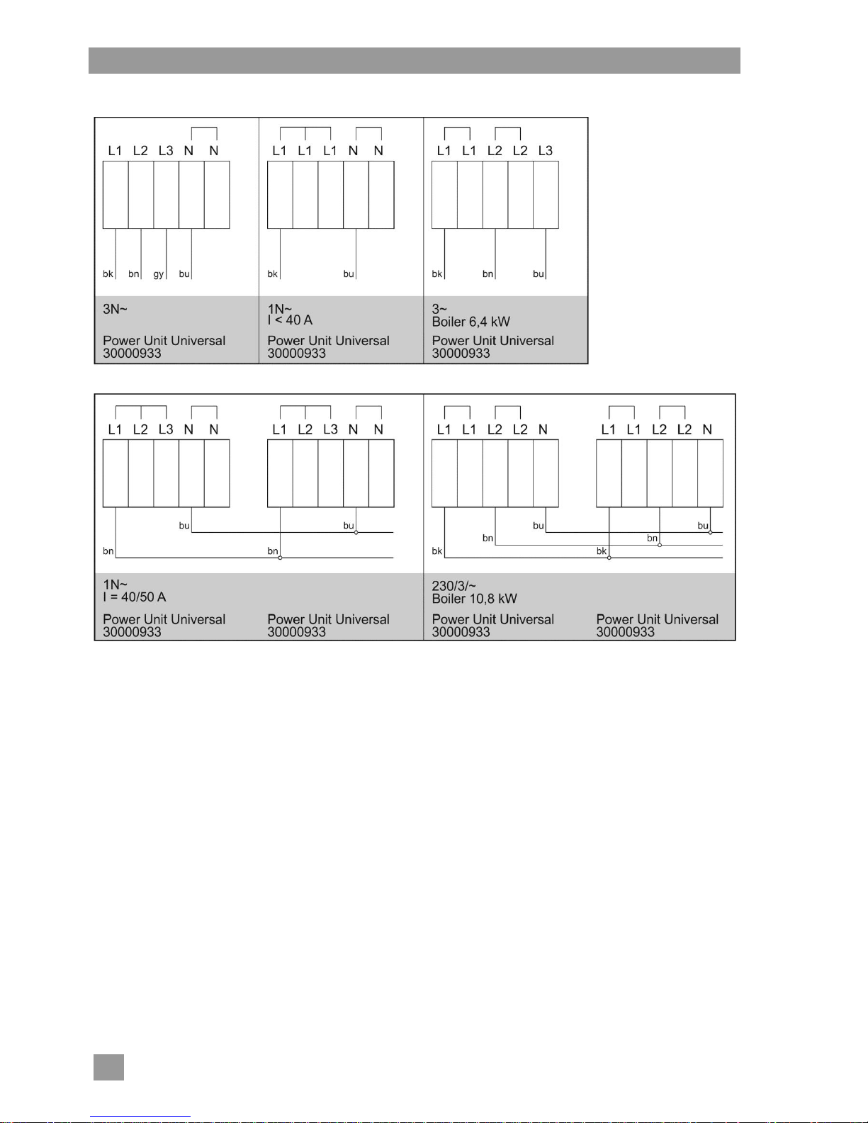
The circuit diagram must be observed.
The equipment may only be operated at the voltages and
frequencies specified on the rating plate.
A fixed connection must as a priority be installed for ma-
chines that are delivered without a plug.
When the machine must be permanently connected (with-
out a plug), a mains disconnector with all-pole separation
from the network must be installed. The mains disconnector
switch must have a contact opening width of at least 3 mm,
and must also be lockable in the neutral position.
The electrical connection must be secured as a separately
fused circuit with slow fuses or circuit breakers. The protection depends on the total power consumption of the machine. The total connected load is specified on the rating
plate of the machine.
Build a residual-current circuit breaker into the electrical
supply line.
Machines delivered from the factory equipped with mains
cable and safety plug (single phase), or CEE plug are (triple
phase), may only be connected to the mains network indicated on the nameplate.
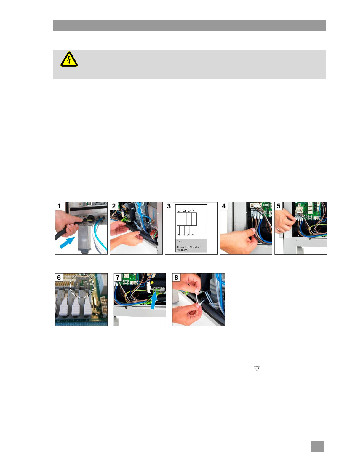
15.1 Connecting the mains cable
Requirements for the mains cable
Cable type: Type H07 RN-F or equivalent
The wires must be fitted with wire end ferrules.
Cross section and number of cores: suitable for on-site power and protection
for more information see the sticker in the front panel
Connect the mains
cable to the rear of the
machine.
Withdraw the mains
cable at the front and
route it to the left.
Follow the connection
diagram ( 15.3).
Connect the wires of the
mains cable according
to the wiring diagram.
Close the quick release
connectors.
If necessary plug bridges.
Firmly press the bridges
with a screwdriver.
Connect the green-yellow
wire to the distributor of
the earth wires.
Attach the mains cable to
the mounting plate with a
cable tie for strain relief.
15.2 Establishing an earth connection
Connect the machine into the equipotential bonding system.
INFO The terminal screw is located behind the right rear leg of the machine. It is identified with the symbol.
Page 24
Electrical connection
22
15.3 Connection diagram
Page 25
External dosing devices
23
16 External dosing devices
Instead of the integral dosing device, external dosing devices can also be used. Follow the instructions in
this section. Additional information can be found in German and English on the Winterhalter web site
(Dosiertechnik / Dosing systems).
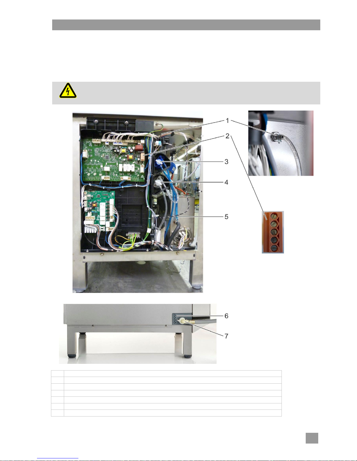
16.1 Terminals
Danger
Danger to life. Live components.
Get the dosing device installed and commissioned by a service engineer authorised by
Winterhalter.
1
Detergent dosing nipple
2
Transfer strip with red plug for the connection of an external dosing device
3
Rinse aid dosing device
4
Detergent dosing device (special equipment)
5
Rinse aid dosing nipple
6
Bushings for cables and hoses
7
Water supply hose
Page 26
External dosing devices
24
16.2 Electrical connection
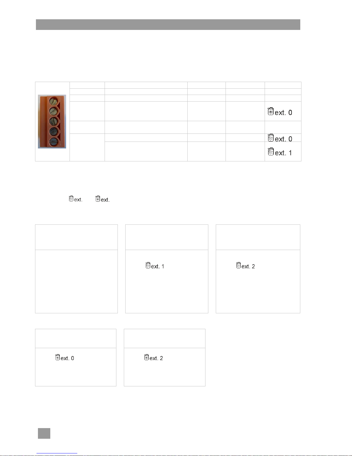
IMPORTANT maximum current drain at the transfer strip: 0.5 A.
Connect the external dosing device to the 5-pin pug.
Terminals (arranged from top to bottom)
Terminal
Voltage is on
Condition
Restriction
Setting
L1
continuous voltage
N
Rinse
(O18)
parallel to solenoid valve (O7)
while the machine is filling
during rinsing
a)
c)
Wash
(O20)
while the circulating pump is
running
a)
c), d), e)
Fill / Water
(O17)
while the machine is filling
a), b)
parallel to solenoid valve (O7)
while the machine is filling
during rinsing
a)
c)
a) only with the hood closed
b) minimum water level in the tank
c) not in the self-cleaning programme
d) not while the machine is filling
The settings and control when a voltage is present at the Fill/Water and Rinse terminals.
Connecting an external detergent dosing device
Example 1:
Hose pump with time-delay
relay and fixed output
Example 2:
Hose pump with adjustable
output
Example 3:
Hose pump with fixed output
(e. g. ESP 166, ESP 166C,
SP 166Z)
Connect to “Wash” terminal.
Set time-delay relay on the
dosing device.
Connect to “Fill/Water” ter-
minal.
Set .
Set output on the dosing
device.
Connect to “Fill/Water” termi-
nal.
Set .
Set both potentiometers to
maximum.
Set dosing amount on the
machine.
If the capacity is not equal to
166 ml/min, set P706 (see
service instructions).
Connecting an external rinse aid dosing device
Example 1:
Hose pump with adjustable
output
Example 2:
Hose pump with fixed output
(16 ml/min) (e.g. SP 16K )
Connect to “Rinse” terminal.
Set .
Set output on the dosing
device.
Connect to “Rinse” terminal.
Set .
Set potentiometer to maxi-
mum.
Set dosing amount on the
machine.
Page 27
Taking the machine out of service for a long period
25
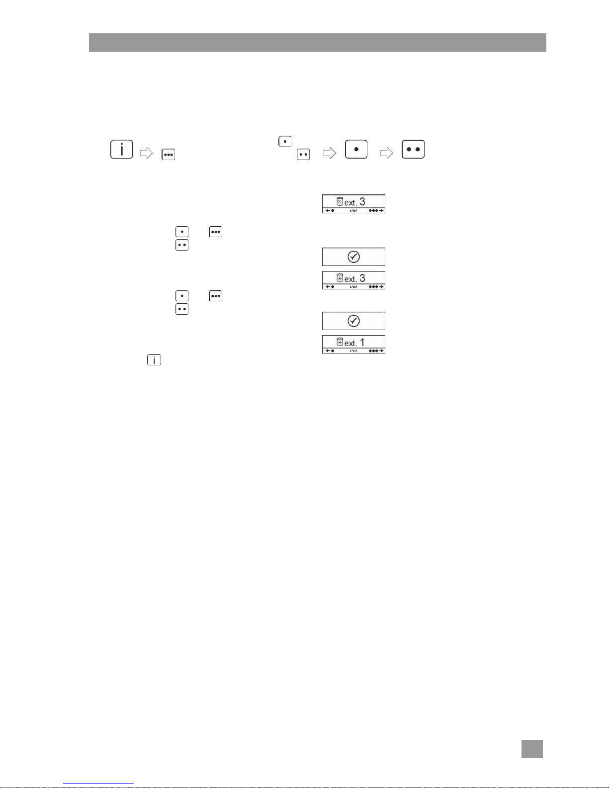
16.3 Changing the settings
Retrieving the settings
Press the following buttons in turn:
3x
Enter "1575"
(change the values with the and
buttons and confirm with the
button)
The setting (detergent) is displayed (number
flashes).
Change with the and buttons.
Confirm with the button.
The input is confirmed.
The setting (rinse aid) is displayed (number
flashes).
Change with the and buttons.
Confirm with the button.
The input is confirmed.
The new setting (rinse aid) is displayed
(number flashes).
Press the button to go back.
1x: The setting (detergent) is displayed
(number flashes).
2x: The output screen is displayed.
3x: Exit the PIN menu.
17 Taking the machine out of service for a long period
Follow the notes if the machine needs to be out of operation for a long duration (holidays, seasonal business).
Empty the machine using the self-cleaning programme ( 8.1.2).
Clean the machine ( 8.1.3 and 8.1.4).
Leave the hood open.
Close the on-site water stop cock.
Switch off the local mains disconnector.
If the machine is in a place that is not frost-free:
Instruct an authorised service technician to make the machine frost-resistant.
18 Putting the machine back into service after a long period of disuse
Open the on-site water stop cock.
Switch on the local mains disconnector.
Switch on the machine.
If the machine was in a place that was not frost-free:
After extended periods of disuse, the machine must be completely climatised (at least 24 hours at 25 °C). If
this requirement is met:
Contact an authorised service technician to put the machine back into service.
Page 28
Technical data
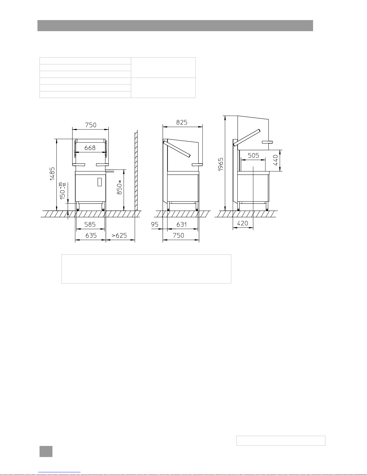
26
19 Technical data
Voltage
see rating plate
Total connection value
Fuse
Minimum flow pressure
14.1
Maximum inlet pressure
Water inlet temperature
Dimensions
20 Emissions
Noise
Workplace-related emission sound pressure level Leq < 63 dB(A)
Measurement uncertainty: K(pA): 4 dB
Exhaust air
Adhere to the VDI Guideline 2052 when designing the ventilation system.
21 Disposal
Contact your dealer so that the materials in the machine can be reused or disposed in accordance with local
legislation.
*) Standard working height is 850 mm which can be optionally
increased to 900 mm.
The vertical dimensions are increased by 50 mm by this.
89013498-02; 2016-07; Changes reserved
Page 29
Page 30
Winterhalter Gastronom GmbH
Gewerbliche Spülsysteme
Winterhalterstraße 2–12
88074 Meckenbeuren
Deutschland
Telefon +49 (0) 75 42/4 02-0
Telefax +49 (0) 75 42/4 02-1 87
www.winterhalter.de
[email protected]
Winterhalter Gastronom GmbH
Commercial Dishwashing Systems
Winterhalterstraße 2–12
88074 Meckenbeuren
Germany
Telephone +49 (0) 75 42/4 02-0
Telefax +49 (0) 75 42/4 02-1 87
www.winterhalter.biz
[email protected]
 Loading...