

Page 1
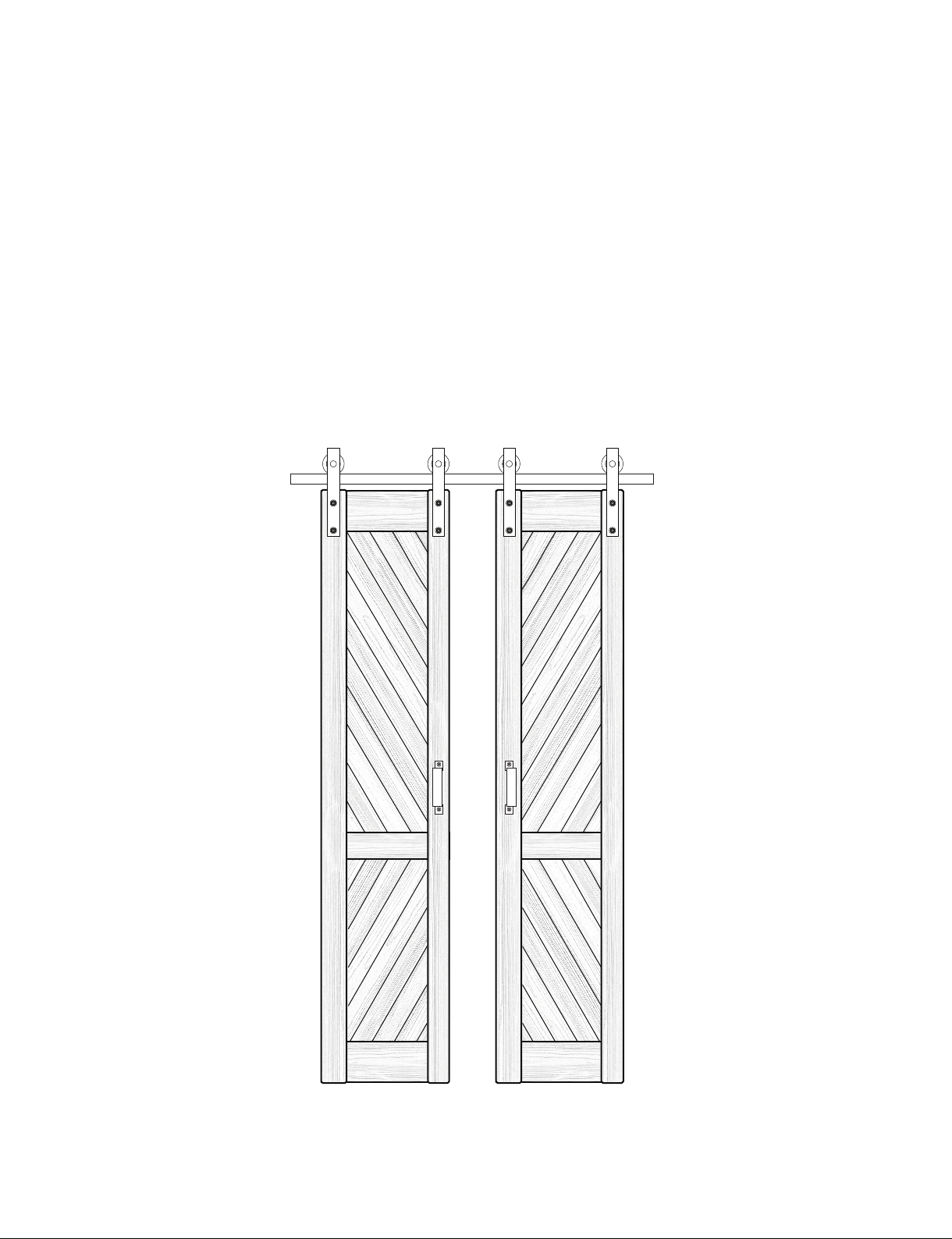
DOUBLE H BARN DOOR
ASSEMBLY INSTRUCTIONS
Page 2
INSTALLATION GUIDE / GUÍA DE INSTALACIÓN
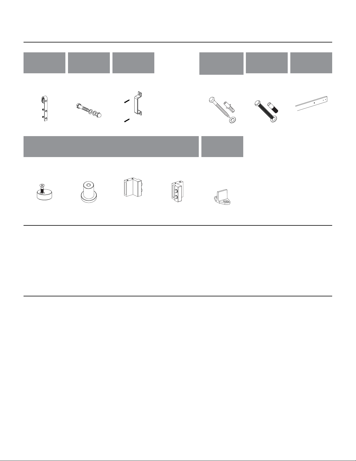
BARN DOOR BI-PART HARDWARE KIT /KIT DE HERRAJES PARA PUERTA DE DOS HOJAS ESTILO COBERTIZO
STRAP HARDWARE /
HERRAJES DE FLEJE
Bent Strap with moutning bolts
/ Placa metálica con pernos
para montaje
BD552
Anti-Jump Block /
Bloque anti-salto
BD790
STRAP BOLTS /
PERNOS DE FLEJE
1 3/8" thick door Strap Bolt /
Perno para placa metálica
de puerta de 3.5 cm de grosor
BD130
COMMON HARDWARE /
HERRAJES COMUNES
Wall Spacer /
Espaciador de pared
BD350
HANDLE /
MANIJA
Handle /
Manija
BD450
Left Stopper /
Tope izquierdo
BD850
(LEFT / IZQUIERDA)
Right Stopper /
Tope derecho
BD850
(RIGHT / DERECHA)
SCREWS
5/16 Drywall Screw & Anchor /
Anclaje y tornillo para drywall,
5/16
BD136
FLOOR GUIDE /
GUÍA DE PISO
Internal Floor-Mounted
Door Guide (with screws) /
Guía para montaje interno
de puerta en piso (con tornillos)
BD750
CONCRE TE BOLTS /
PERNOS PARA
CONCRETO
5/16 Track Mounting
Carriage Bolt /
Perno de carro para montaje
de riel, 5/16
BD134
78 3/4" TRACK /
RIEL DE 200 CM
78 3/4" Track (5 holes) /
Riel de 2 m (5 orificios)
BD5000-07800
TOOLS REQUIRED: Measuring Tape, Pencil, Stud Finder (for drywall installation only), Cordless Drill, Set of Drill Bits, Wrench, Socket Wrench Set, Screw Driver Set, Hammer and Level.
DRYWALL INSTALLATION: If installing directly into a non-concrete wall like drywall, do not attempt to install the track solely onto the wall surface as this may not support the weight of
the track and mounted door. The track must be installed onto a piece of solid wood blocking that has been secured using mounting screws into the wall studs. Use a stud nder where
necessary to locate studs and secure safely above your opening in the correct location. Once secured safely, the wood blocking will support the track by fastening each track mounting
screw with anchor into both the wood blocking onto the wall.
CONCRETE INSTALLATION: If installing into a concrete, secure directly using the track mounting carriage bolts. Note, the wood blocking will not be required for this installation.
drywall
HERRAMIENTAS NECESARIAS: Cinta de medir, lápiz, detector de vigas (sólo para instalación en
), taladro inalámbrico, juego de brocas de taladro, llave, juego de llaves de dados,
juego de destornilladores, martillo y nivel.
INSTALACIÓN EN
DRYWALL
: Si la instalación se realiza directamente en una pared que no es de concreto, por ejemplo:
drywall
, no intentes instalar el riel solo en la supercie de la
pared, ya que posiblemente no resista el peso del riel y la p uerta instalada. El riel debe instalarse sobre un bloque de madera maciza asegurado con tornillos de montaje insertados
en las vigas de la pared. Utiliza un detector de vigas si es necesario para localizarlas y asegurar bien por encima del vano en la ubicación actual. Una vez bien asegurado, el bloque de
madera servirá de soporte al riel, jando cada tornillo de montaje con anclaje del riel dentro del bloque de madera y de la pared.
INSTALACIÓN EN CONCRETO: Si la instalación es en concreto, asegura directamente con los pernos de cabeza redonda para montar el riel. Ten en cuenta que no se necesitará el bloque
de madera para este tipo de instalación.
Page 3
INSTALLATION GUIDE / GUÍA DE INSTALACIÓN
BARN DOOR BI-PART HARDWARE KIT /KIT DE HERRAJES PARA PUERTA DE DOS HOJAS ESTILO COBERTIZO
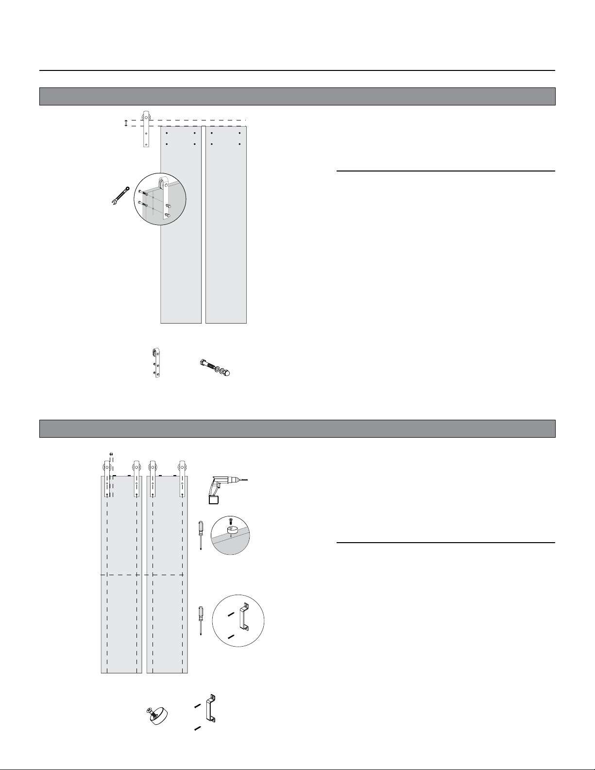
BENT STRAP BARN DOOR PREPARATION / PREPARACIÓN DE LA PUERTA ESTILO COBERTIZO CON FLEJE DOBLADO
2 in
x4 Bent Strap
x4 Correa curva
BD552
x8 Standard 1 3/8" Thick Door Strap Bolt
x8 Estándar. 1 3/8" Perno de la correa
de la puerta gruesa
BD130
Barn Doors are supplied with strap mounting holes pre-drilled. Install both
sets of straps to each door securely with the 1 3/8" bolts provided using a
socket wrench as shown. Use a wrench to hold the nuts in place when securing
the bolts for a tight install.
Las puertas estilo cobertizo se suministran con oricios pre-taladrados para
el montaje de placas metálicas. Instala de manera segura ambos juegos de
placas metálicas en cada puerta con los pernos de 1 3/8 plg incluidos, usando
una llave de dados como se muestra. Usa una llave para mantener las tuercas
en su lugar al apretar los pernos en instalación ajustada.
1 in
x4 Anti-Jump Block
x 4 Bloque anti-salto
ANTI-JUMP AND HANDLE PREPARATION / PREPARACIÓN DEL BLOQUE ANTISALTO Y LA MANIJA
Position each anti-jump block at least 1" from the edge of the strap edge
as shown. Center the block on the top of the door with the screw hole facing
outwards as shown. Mark the holes with a pencil and pre-drill 1/8" pilot holes.
Tighten slightly to secure in place allowing the blocks to rotate to clear the
track when installing.
Position the handle center to the strap or stile and half-way-up the door or
center to any H rails on the door as shown. Mark holes with a pencil and predrill 1/8" pilot holes before securing the handle into place.
Ubica cada bloque anti-salto a 2.5 cm como mínimo del borde de la placa
metálica, tal como se muestra. Centra el bloque en la parte superior de la
puerta con el oricio de tornillo mirando hacia afuera, tal como se muestra.
Marca los oricios con un lápiz y pre-taladra oricios pilotos de 1/8 plg. Ajusta
ligeramente para asegurar en el lugar y deja que los bloques giren para no
obstruir el riel durante la instalación.
Coloca el centro de la manija en la placa metálica o el listón vertical, a la mitad
de la altur a de la puerta o en e l centro de cualq uier listón en H de el la, tal como se
muestr a. Marca los or i cios co n un lápiz y pr e-tala dr a or i cios pilo to s de 1/8 pl g
antes de asegurar la manija en su lugar.
x2 Handle
x2 Manija
BD790
BD450
Page 4
INSTALLATION GUIDE / GUÍA DE INSTALACIÓN
BARN DOOR BI-PART HARDWARE KIT /KIT DE HERRAJES PARA PUERTA DE DOS HOJAS ESTILO COBERTIZO
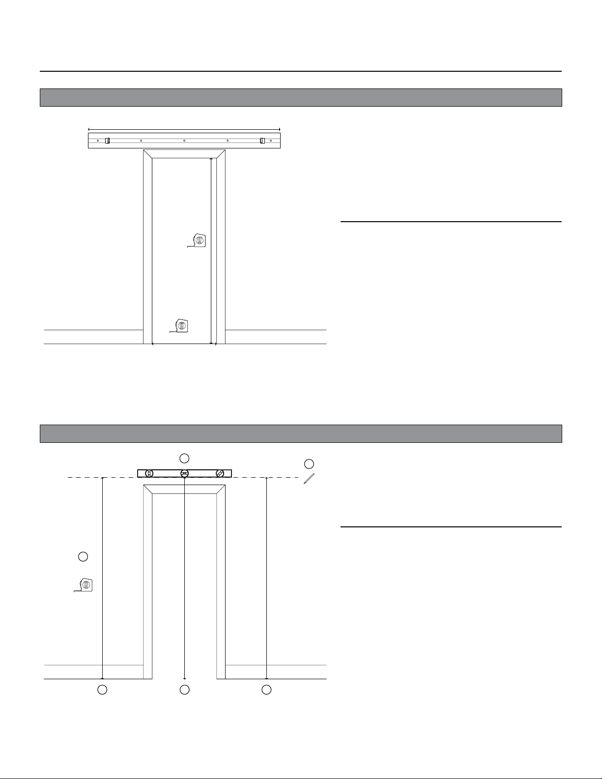
STEP 01A | DRY WALL INSTALL ATION - OPENING SIZE / PASO 01A | INSTAL ACIÓN EN
78 3/4 in
FOR CONCRETE WALL INSTALLATION, FOLLOW INSTRUCTION STEPS B.
Each barn door is manufactured to 18" wide by 84" high to create a bi-parting
system on a 78 3/4 " track. The recommended opening dimension with barn
door hardware mounted is 28" – 32" wide openings x 80 1/2" height with
trim, and up to 83" height without trim.
As a guide, the center of the track should be installed center to the opening for
optimal operation. Drywall installation must utilize the track mounting screw
with anchor hardware supplied onto a solid wood blocking attached to your
wall. Note, screws to secure the wood blocking are sold separately.
80 1/2 in
PARA INSTALACIÓN EN PARED DE CONCRETO, SIGUE LOS PASOS DE LAS INS TRUCCIONES B
Cada puerta estilo cobertizo se fabrica con 45.7 cm de ancho y 213.4 cm de
altura pa ra crear un sistema de d oble partición en riel de 200 cm. L a dimensión
recomendada del vano con los herrajes de la puerta estilo cobertizo instalados
es entre 71.1 cm y 81.3 cm de ancho x 204.5 cm de altura con moldura y hasta
210.8 cm sin moldura.
Como una guía, el centro del riel debe instalarse en el centro del vano para
operación óptima. En la instalación en
montaje de riel con anclaje incluido sobre un bloque de madera maciza jado
28 in - 32 in
a la pared. Ten en cuenta que los tornillos para asegurar el bloque de madera
se venden por separado.
DRYWALL
- TAMAÑO DEL VANO
drywall
debe usarse el tornillo de
STEP 02A | DRYWALL INSTALLATION - OPENING SIZE / PASO 02A | INSTAL ACIÓN EN
2
1
85 3/4 in
A B C
DRYWALL
- TAMAÑO DEL VANO
3
For optimal clearance and operation, measure at three locations (A, B and C)
85 3/4" (door height + 1 3/4") to the left, center and right of the opening
based on the length of the 78 3/4" as shown (Figure 01).
Using a level, determine which measurement is the highest as this will locate
the track position for installation (Figure 02). Mark with a pencil a level
installation line across your opening (Figure 03).
Para espacio y operación óptimos, mide en tres lugares (A, B y C) 217.8 cm
(altura de la puerta + 4.4 cm) hacia la izquierda, el centro y la derecha del
vano basado en el largo de 200 cm, como se muestra (Figura 01).
Determina con un nivel qué medida es la más alta, así quedará ubicada la
posición del riel para la instalación (Figura 02). Marca con un lápiz una línea
de instalación nivelada a lo largo del vano (Figura 03).
01A/ 02A
Page 5
INSTALLATION GUIDE / GUÍA DE INSTALACIÓN
BARN DOOR BI-PART HARDWARE KIT /KIT DE HERRAJES PARA PUERTA DE DOS HOJAS ESTILO COBERTIZO
STEP 03A| DRYWALL INSTALL ATION - WOOD BLOCKING / PASO 03A| INSTALACIÓN EN
2
DRYWALL
- BLOQUE DE MADERA
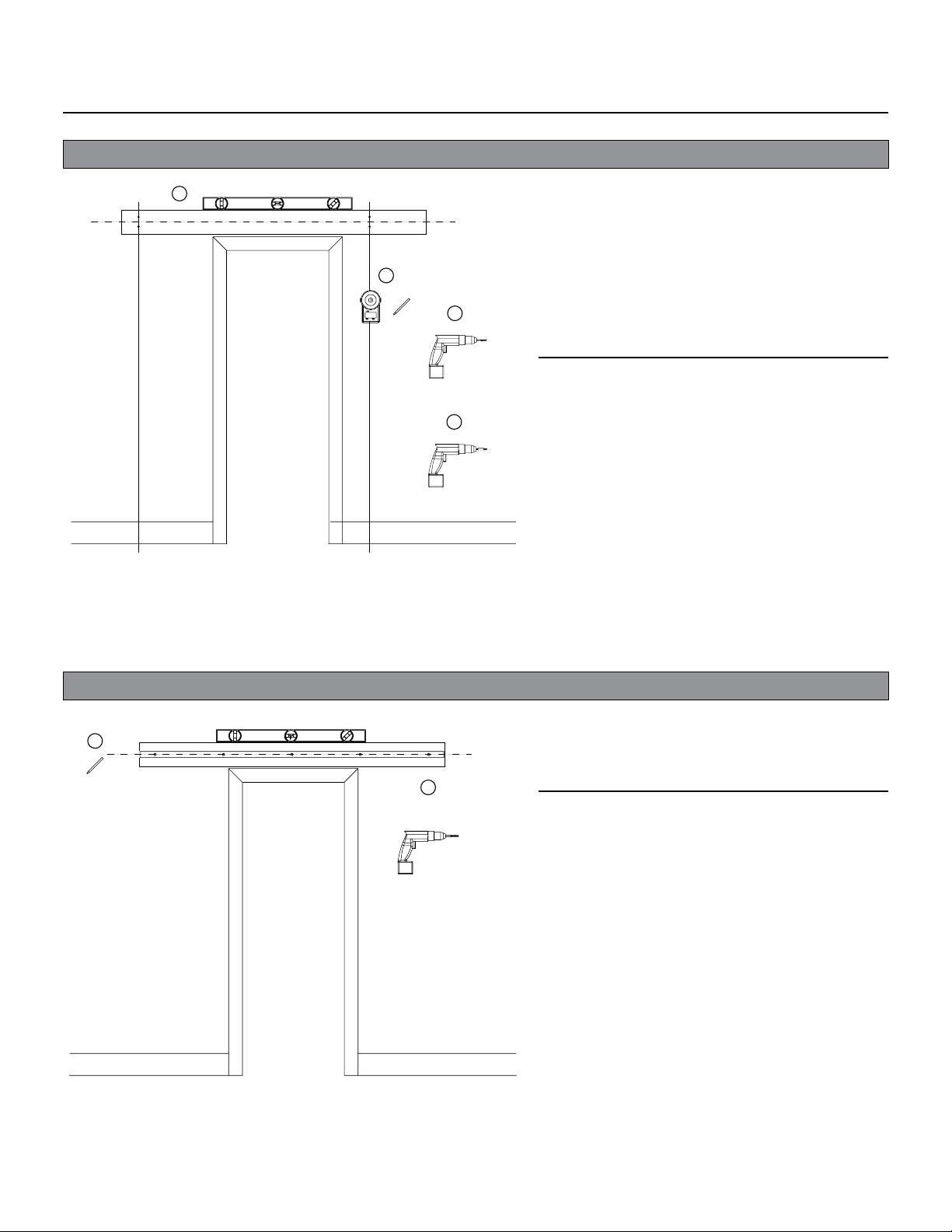
Using a stud nder, locate and mark with a pencil where studs intersect
with the installation line across your opening (Figure 01). Position the wood
blocking aligned center to the installation line ensuring the block is level and
the middle of the board is aligned to the off-center of the jamb opening (where
the track center will be located) as shown (Figure 02).
1
3
Secure the wood blocking with screws by pre-drilling holes and mounting
screws into the studs (Figures 03 and 04). Note: Mounting screws are sold
separately. Additional drywall anchors can be purchased and installed for
additional support if so desired.
Con un detector de vigas, ubica y marca con un lápiz el lugar donde las
4
vigas se cruzan con la línea de instalación a lo largo del vano (Figura 01).
Coloca el bloque de madera alineado con el centro de la línea de instalación,
asegurando que esté nivelado y que el medio del tablón quede alineado con el
centro del vano de la jamba (donde se encontrará el centro del riel), tal como
se muestra (Figura 02).
Asegura el bloque de madera con tornillos, pre-taladrando los oricios e
insertando los tornillos en las vigas (Figuras 01 y 04). Nota: Los tornillos
de montaje se venden por separado. Otros anclajes para
drywall
pueden
comprarse e instalarse con vistas a un soporte adicional si se desea.
STEP 04A | DRYWALL INSTALLATION - WALL PREPARATION / PASO 04A | INSTAL ACIÓN EN
DRYWALL
- PREPAR ACIÓN DE LA PARED
Position the track in place ensuring that it is level along the installation line
1
at center, mark the holes on the track using a pencil (Figure 01) and pre-drill
3/8" holes into the wood blocking and into your drywall (Figure 02).
2
3/8 in
Ubica el riel en su lugar, asegurando que esté nivelado a lo largo de la línea de
instalación en el centro; marca con un lápiz los oricios en el riel (Figura 01)
y pre-taladra los oricios de 3/8 plg en el bloque de madera y dentro del
drywall
(Figura 02).
03A / 04A
Page 6
INSTALLATION GUIDE / GUÍA DE INSTALACIÓN
23
BARN DOOR BI-PART HARDWARE KIT /KIT DE HERRAJES PARA PUERTA DE DOS HOJAS ESTILO COBERTIZO
x1 Wood Block for drywall
installation only
x1 Bloque de madera sólo
para instalación en drywall
x1 78 3/4" Track (5 holes)
x1 Riel de 2 m (5 orificios)
STEP 05A | DRYWALL INSTALLATION - TRACK INSTALL ATION / PASO 05A | INSTALACIÓN EN
1
54
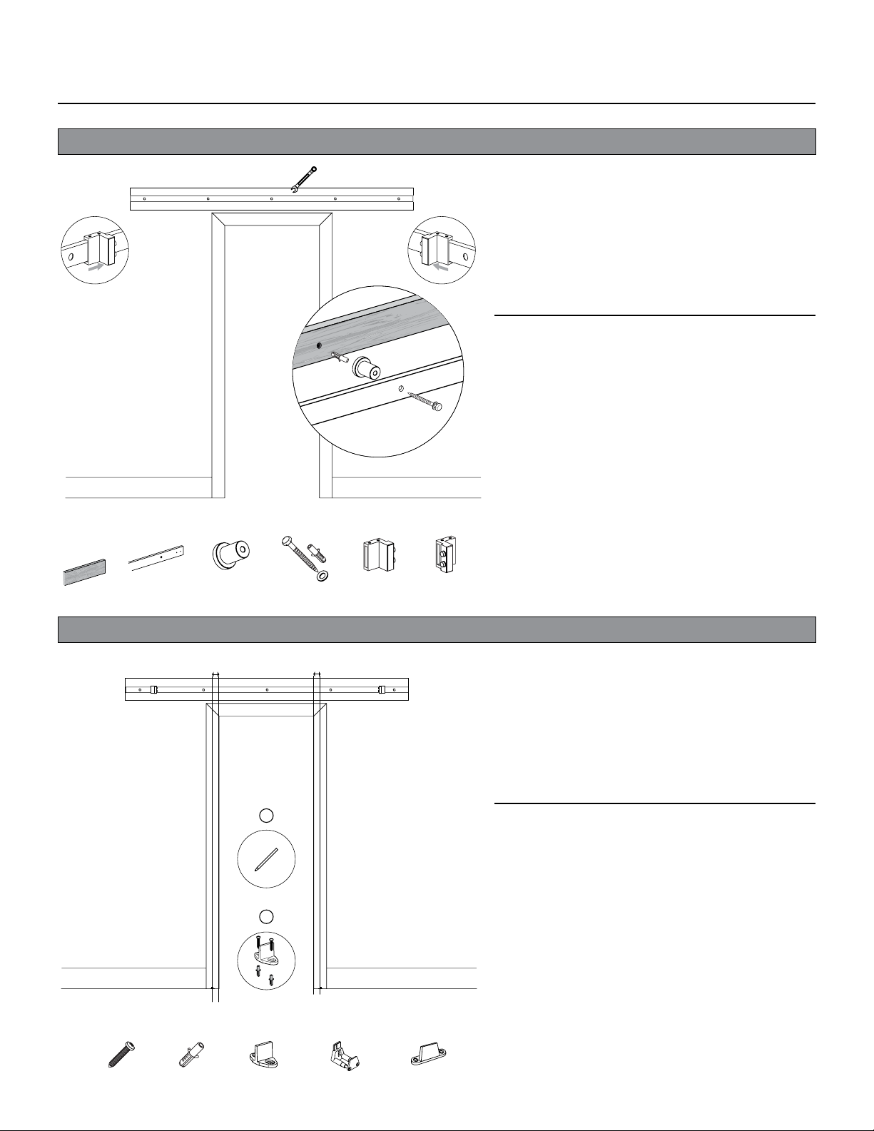
When installing directly into drywall, position the track and insert the anchors
and screws (with washers) provided into the wood blocking, securing with a
socket wrench. Ensure to insert the anchors into the wood blocking rst. For
ease, secure at center rst, then secure the outer holes followed by the internal
holes (1-5) as shown. Once secured, each anchor will expand into the wood
blocking and drywall.
Note: It may be necessary to pre-insert the left and right stoppers inside the
outside holes on the track.
Al instalar directamente en
tornillos (con arandelas) incluidos en el bloque de madera, asegurando con
una llave de dados. Asegúrate de insertar los anclajes primero en el bloque
de madera. Para mayor facilidad, asegura el centro primero, enseguida
los oricios exteriores y por último los oricios interiores (1-5), tal como se
muestra. Una vez asegurados, cada anclaje se expandirá en el bloque de
madera y el
Nota: Puede que sea necesario pre-insertar los topes izquierdo y derecho
dentro de los oricios exteriores del riel.
x5 Wall Spacer
x5 Espaciador de pared
x5 3/8 Drywall Screw & Anchor
x5 Anclaje y tornillo para drywall de 3/8
x1 Left Stopper
x1 Tope izquierdo
x1 Right Stopper
x1 Tope derecho
DRYWALL
- INSTALACIÓN DEL RIEL
drywall
.
drywall
, ubica el riel e inserta los anclajes y
BD850 BD850 BD5000 BD350 BD136
STEP 06A| DRYWALL INSTALLATION - FLOOR GUIDE / PASO 06A| INSTALACIÓN EN
1-1/2 in
1-1/2 in
Position each standard oor-mounted door guide 1 1/2" off-center to the jamb
at each side. These guides are designed to operate inside each pre-mortised barn
door. Mark holes with a pencil (Figure 01) and pre-drill 1/8" holes if necessary.
If drilling directly into a solid oor, use the provided anchors (Figure 02) before
DRYWALL
- GUÍA DE PISO
securing screws.
If you do not wish to use the standard oor-mounted guides, a set of wall mounted
guides and two sets of oor mounted guides are also included in your kit. Both
these guides options should be mounted near the same location and operate on
the outside surface of each door.
1
Coloca cada guía de puerta para montaje en piso estándar a 3.8 cm del centro
de la jamba a cada lado. Estas guías están diseñadas para funcionar dentro de
cada puerta estilo cobertizo con encaje previo para cerradura. Marca oricios con
un lápiz (Figura 01) y pretaladra oricios de 1/8 plg si es necesario. Si taladras
directamente sobre un piso macizo, usa los anclajes incluidos (Figura 02) antes de
2
asegurar con tornillos.
Si no deseas usar las guías para montaje en piso estándar, el kit también incluye
un juego de guías para montaje en la pared y dos juegos de guías para montaje en
el piso. Para ambas opciones de guías debe instalarse cerca de la misma ubicación
y funcionar en la supercie exterior de cada puerta.
x2 #8 Floor Screws
x2 Tornillos núm. 8 para piso
BD750 BD750 BD750 99161 99161
x2 1/4 Floor Anchor
x2 Anclaje de 1/4 para piso
x1 Internal Floor-Mounted
Door Guide
x1 Guía para montaje interno
de puerta en piso
x1 Optional Wall-Mounted Door
Guide (with screws)
x1 Guía para montaje opcional
de puerta en pared (con tornillos)
x2 Optional Floor-Mounted Door Guide
(with screws)
x2 Guía para montaje opcional de puerta
en piso (con tornillos)
05A/ 06A
Page 7
INSTALLATION GUIDE / GUÍA DE INSTALACIÓN
BARN DOOR BI-PART HARDWARE KIT / KIT DE HERRAJES PARA PUERTA DE DOS HOJAS ESTILO COBERTIZO
STEP 07A | DRYWALL INSTALLATION - OPERATION / PASO 07A | INSTALACIÓN EN
DRYWALL
- OPERACIÓN
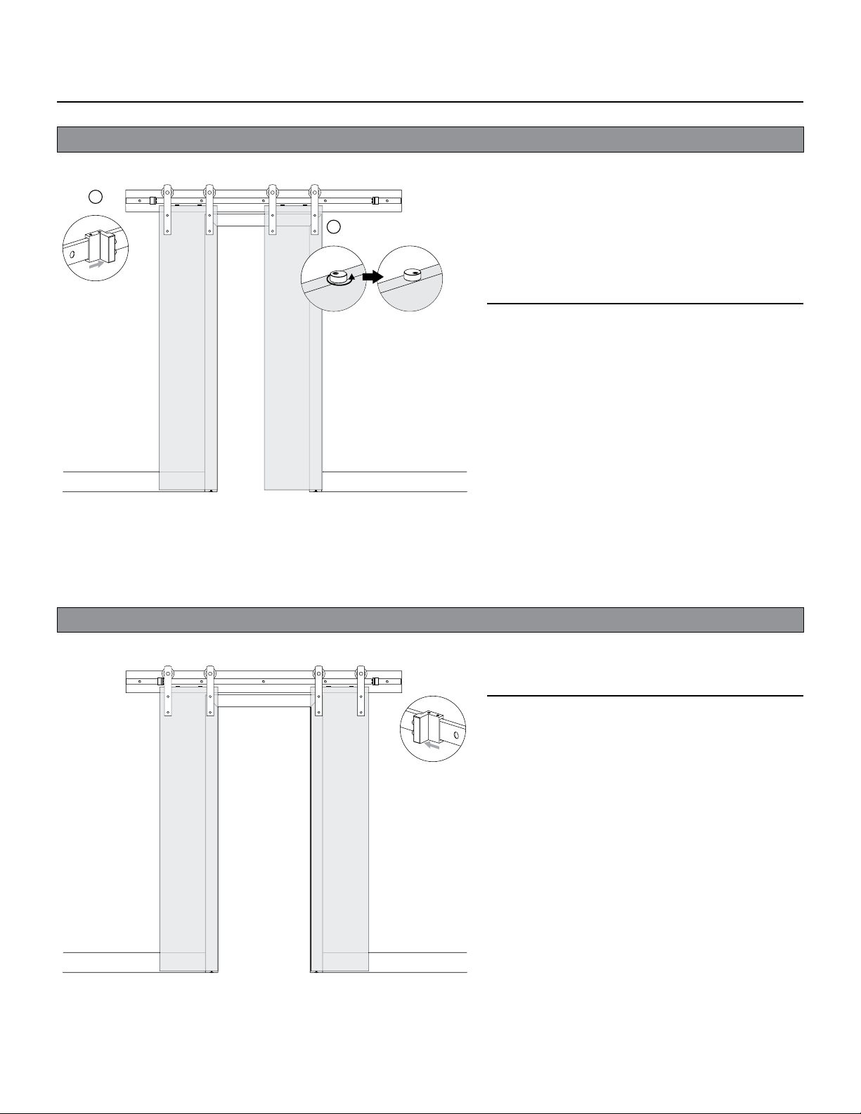
Rotate the anti-jump blocks outwards before mounting each door. Lift and
2
place the door and position the wheels so they sit directly onto the secured
track. Once the door is in position, rotate the anti-jump blocks back into
position directly under the track (Figure 01). Tighten each anti-jump block
1
once you have ensured all parts are operating correctly by sliding the door
side-to-side ensuring that the door operates with the mounted oor guide.
With the door in the closed position, secure the stopper in place with the Allen
Key provided (Figure 02).
Gira los bloques anti-salto hacia afuera antes de instalar cada puerta. Levanta
y coloca la puerta; ubica las ruedas de forma tal que queden directamente
sobre el riel asegurado. Una vez que la puerta esté ubicada, gira los bloques
anti-salto de vuelta a su posición directamente debajo del riel (Figura 01).
Ajusta cada bloque anti-salto cuando hayas asegurado que todas las piezas
funcionan correctamente al deslizar la puerta a ambos lados, así como que la
puerta funciona con la guía de piso instalada.
Con la puerta cerrada, asegura el tope en su lugar con la llave Allen incluida
(Figura 02).
STEP 08A | DRYWALL INSTALLATION - ADJUSTMENT / PASO 08A | INSTALACIÓN EN
Slide the second door across to the open position and with the door in the ideal
location, secure the stopper in place as shown to complete the installation.
Desliza la segunda puerta a lo largo de la posición abierta y, con la puerta
en la posición ideal, asegura el tope en su lugar, como se muestra, para
completar la instalación.
DRYWALL
- AJUSTE
07A / 08A
Page 8
CONCRETE INSTALLATION GUIDE / GUÍA DE INSTALACIÓN EN CONCRETO
BARN DOOR BI-PART HARDWARE KIT /KIT DE HERRAJES PARA PUERTA DE DOS HOJAS ESTILO COBERTIZO
STEP 01B | CONCRETE INSTALLATION - OPENING SIZE / PASO 01B | INSTALACIÓN EN CONCRETO - TAMAÑO DEL VANO
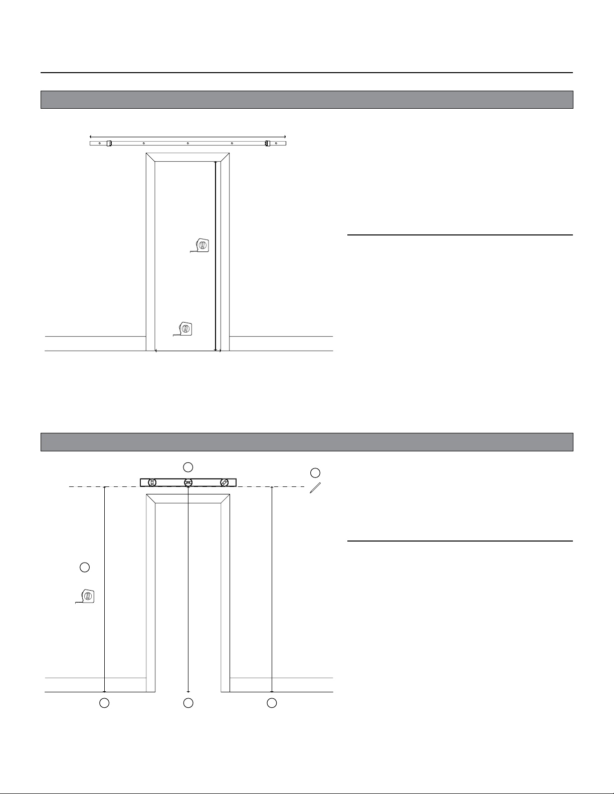
78 3/4 in
28 in - 32 in
80 1/2 in
FOR DRYWALL INSTALLATION, FOLLOW INSTRUCTION STEPS A.
Each barn door is manufactured to 18" wide by 84" high to create a bi-parting
system on a 78 3/4 " track. The recommended opening dimension with barn
door hardware mounted is 28" – 32" wide openings x 80 1/2" height with
trim, and up to 83" height without trim.
As a guide, the center of the track should be installed center to the opening
for optimal operation. Concrete installation must utilize the track mounting
carriage bolt hardware to secure to your wall. Note, the wood blocking and
drywall track mounting screws are not required.
PARA INSTALACIÓN EN
DRYWALL
, SIGUE LOS PASOS DE LA INSTRUCCIÓN A.
Cada puerta estilo cobertizo se fabrica con 45.7 cm de ancho y 213.4 cm
de altura para crear un sistema de doble partición en riel de 200 cm. La
dimensión recomendada del vano con los herrajes de la puerta estilo cobertizo
ya instalados es de 71.1 cm a 81.3 cm de ancho x 204.5 cm de altura, con
moldura, y hasta 210.8 cm sin ella.
Como una guía, el centro del riel debe instalarse en el centro del vano para
operación óptima. La instalación en concreto tiene que utilizar pernos de carro
para el montaje del riel al efecto de asegurarlo a la pared. Ten en cuenta que
no son necesarios ni el bloque de madera ni los tornillos de montaje del riel
en
drywall
.
STEP 02B | CONCRETE INSTALLATION - MEASUREMENTS / PASO 02B | INSTALACIÓN EN CONCRETO - MEDIDAS
2
1
85 3/4 in
A B C
3
For optimal clearance and operation, measure at three locations (A, B and C)
85 3/4" (door height + 1 3/4") to the left, center and right of the opening
based on the length of the 78 3/4" as shown (Figure 01).
Using a level, determine which measurement is the highest as this will locate
the track position for installation (Figure 02). Mark with a pencil a level
installation line across your opening (Figure 03).
Para espacio y operación óptimos, mide en tres lugares (A, B y C) 217.8 cm
(altura de la puerta + 4.4 cm) hacia la izquierda, el centro y la derecha del
vano basado en el largo de 200 cm, como se muestra (Figura 01).
Determina con un nivel qué medida es la más alta; así quedará ubicada la
posición del riel para la instalación (Figura 02). Marca con un lápiz una línea
de instalación nivelada a lo largo del vano (Figura 03).
01B / 02B
Page 9
CONCRETE INSTALLATION GUIDE / GUÍA DE INSTALACIÓN EN CONCRETO
23
BARN DOOR BI-PART HARDWARE KIT /KIT DE HERRAJES PARA PUERTA DE DOS HOJAS ESTILO COBERTIZO
03B | CONCRETE INSTALLATION - WALL PREPARATION / 03B | INSTALACIÓN EN CONCRETO - PREPARACIÓN DE LA PARED
1
2 3
3/8 in
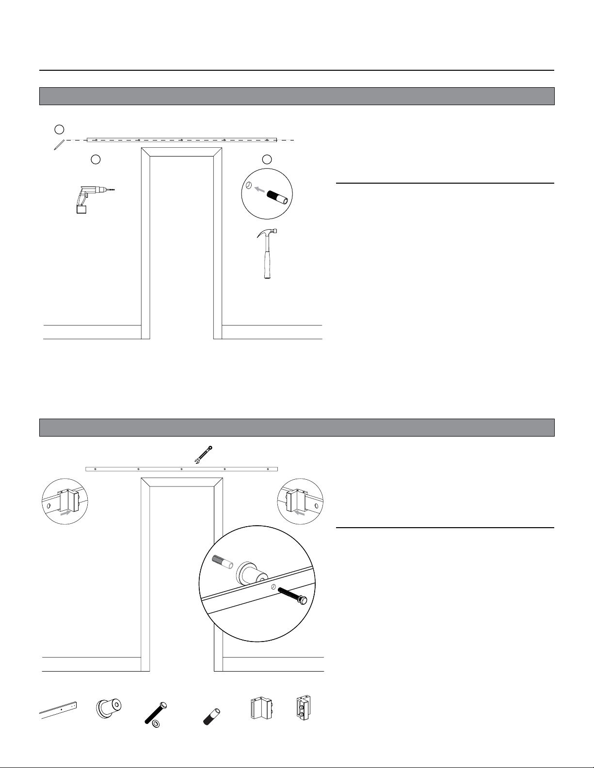
Position the track in place ensuring that it is level along the installation line
at center, mark the holes on the track using a pencil (Figure 01) and pre-drill
3/8" holes into concrete wall (Figure 02).
Separate each carriage from the track mounting bolts and insert into the
concrete wall using a hammer (Figure 03).
Ubica el riel en su lugar, asegurando que esté nivelado a lo largo de la línea de
instalación en el centro; marca con un lápiz los oricios en el riel (Figura 01)
y pre-taladra los oricios de 3/8 plg en la pared de concreto (Figura 02).
Separa cada carro de los pernos de montaje del riel e inserta en la pared de
concreto usando un martillo (Figura 03).
x1 78 3/4" Track (5 holes)
x1 Riel de 2 m (5 orificios)
x5 Wall Spacer
x5 Espaciador de pared
04B | CONCRETE INSTALLATION - TRACK INSTALLATION / 04B | INSTALACIÓN EN CONCRETO - INSTALACIÓN DEL RIEL
1
54
Insert each track mounting bolt (with washer) into each carriage already
inside your wall, securing with a socket wrench. For ease of installation, secure
at center rst, then secure the outer holes followed by the internal holes (1-5)
as shown. Once secured, each carriage will expand into the concrete wall.
Note: It may be necessary to pre-insert the left and right stoppers inside the
outside holes on the track.
Inserta cada perno de montaje de riel (con arandela) dentro de cada carro ya
dentro de la pared, asegurando con una llave de dados. Para una instalación
más fácil, asegura el centro primero, enseguida los oricios exteriores y por
último los oricios interiores (1-5), tal como se muestra. Una vez asegurados,
cada carro se expandirá en la pared de concreto.
Nota: Puede que sea necesario pre-insertar los topes izquierdo y derecho
dentro de los oricios exteriores del riel.
x5 5/16 Solid Wall Carriage Bolt
x5 Perno de carro de 5/16
para pared maciza
x5 5/16 Anchor
(Pre-mounted
to Carriage Bolt)
x5 Anclaje de 5/16
(Preinstalado en el perno de carro)
x1 Left Stopper
x1 Tope izquierdo
x1 Right Stopper
x1 Tope derecho
BD5000 BD350 BD134
03B / 04B
For Solid Wall Installation Only
Sólo para instalación en pared sólida
BD850 BD850
Page 10
CONCRETE INSTALLATION GUIDE / GUÍA DE INSTALACIÓN EN CONCRETO
BARN DOOR BI-PART HARDWARE KIT /KIT DE HERRAJES PARA PUERTA DE DOS HOJAS ESTILO COBERTIZO
05B | CONCRETE INSTALLATION - FLOOR GUIDE / 05B | INSTALACIÓN EN CONCRETO - GUÍA DE PISO
x4 #8 Floor Screws
x4 Tornillos núm. 8 para piso
x4 1/4 Floor Anchor
x4 Anclaje para piso, 1/4
1
2
x2 Internal Floor-Mounted
Door Guide
x2 Guía para montaje interno
de puerta en piso
1-1/2 in1-1/2 in
x2 Optional
Wall-Mounted Door Guide
(with screws)
x2 Guía para montaje opcional
de puerta en pared (con tornillos)
x4 Optional
Floor-Mounted Door Guide
(with screws)
x4 Guía para montaje opcional
de puerta en piso (con tornillos)
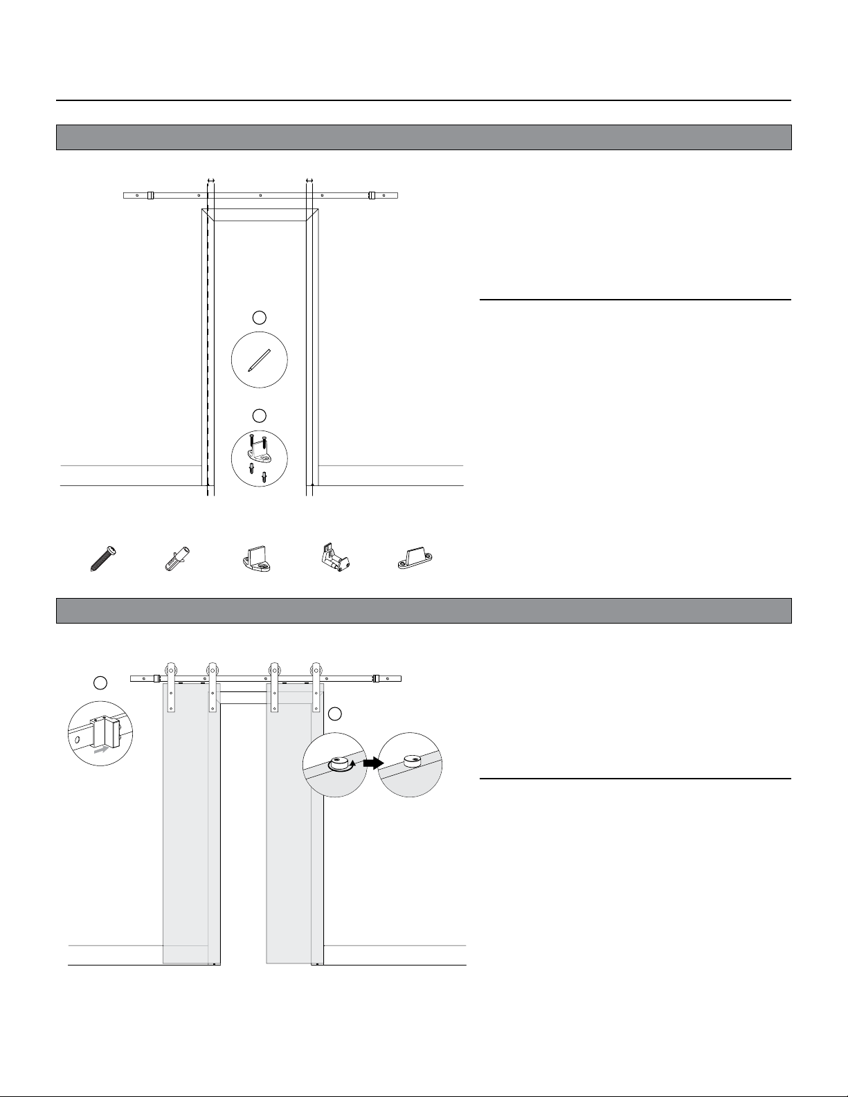
Position each standard oor-mounted door guide 1 1/2" off-center to the jamb at
each side. These guides are designed to operate inside each pre-mortised door. Mark
holes wi th a pencil (Figure 01) and pre -drill 1/8" holes if necessar y. If drilling dire ctly
into a solid oor, use the provided anchors (Figure 02) before securing screws.
If you do not wish to use the standard oor-mounted guides, a set of wall mounted
guides and two sets of oor mounted guides are also included in your kit. Both
these guides options should be mounted near the same location and operate on
the outside surface of each door.
Coloca cada guía de puerta para montaje en piso estándar a 3.8 cm del centro de
la jamba a cada lado. Estas guías están diseñadas para funcionar dentro de cada
puerta con encaje previo para cerradura. Marca oricios con un lápiz (Figura 01)
y pretaladra oricios de 1/8 plg si es necesario. Si taladras directamente sobre un
piso macizo, usa los anclajes incluidos (Figura 02) antes de asegurar con tornillos.
Si no deseas usar las guías para montaje en piso estándar, el kit también incluye
un juego de guías para montaje en la pared y dos juegos de guías para montaje en
el piso. Para ambas opciones de guías debe instalarse cerca de la misma ubicación
y funcionar en la supercie exterior de cada puerta.
BD750 BD750 BD750 99161 99161
06B | CONCRETE INSTALLATION - OPERATION / 06B | INSTALACIÓN EN CONCRETO - OPERACIÓN
2
1
Rotate the anti-jump blocks outwards before mounting each door. Lift and
place the door and position the wheels so they sit directly onto the secured
track. Once the door is in position, rotate the anti-jump blocks back into
position directly under the track (Figure 01). Tighten each anti-jump block
once you have ensured all parts are operating correctly by sliding the door
side-to-side ensuring that the door operates with the mounted oor guide.
With the door in the closed position, secure the stopper in place with the Allen
Key provided (Figure 02).
Gira los bl oques anti- salto hacia afuer a antes de instalar c ada puerta. L evanta y
coloca la puerta; ubica las ruedas de forma tal que queden directamente sobre
el riel ase gurado. Una vez que la p uerta esté ubi cada, gira los blo ques anti-s alto
de vuelta a su posición directamente debajo del riel (Figura 01). Ajusta cada
bloque anti-salto cuando hayas asegurado que todas las piezas funcionan
correctamente al deslizar la puerta a ambos lados, así como que la puerta
funciona con la guía de piso instalada.
Con la puerta cerrada, asegura el tope en su lugar con la llave Allen incluida
(Figura 02).
05B / 06B
Page 11
CONCRETE INSTALLATION GUIDE / GUÍA DE INSTALACIÓN EN CONCRETO
BARN DOOR BI-PART HARDWARE KIT /KIT DE HERRAJES PARA PUERTA DE DOS HOJAS ESTILO COBERTIZO
07B | CONCRETE INSTALLATION - ADJUSTMENT / 07B | INSTALACIÓN EN CONCRETO - AJUSTE
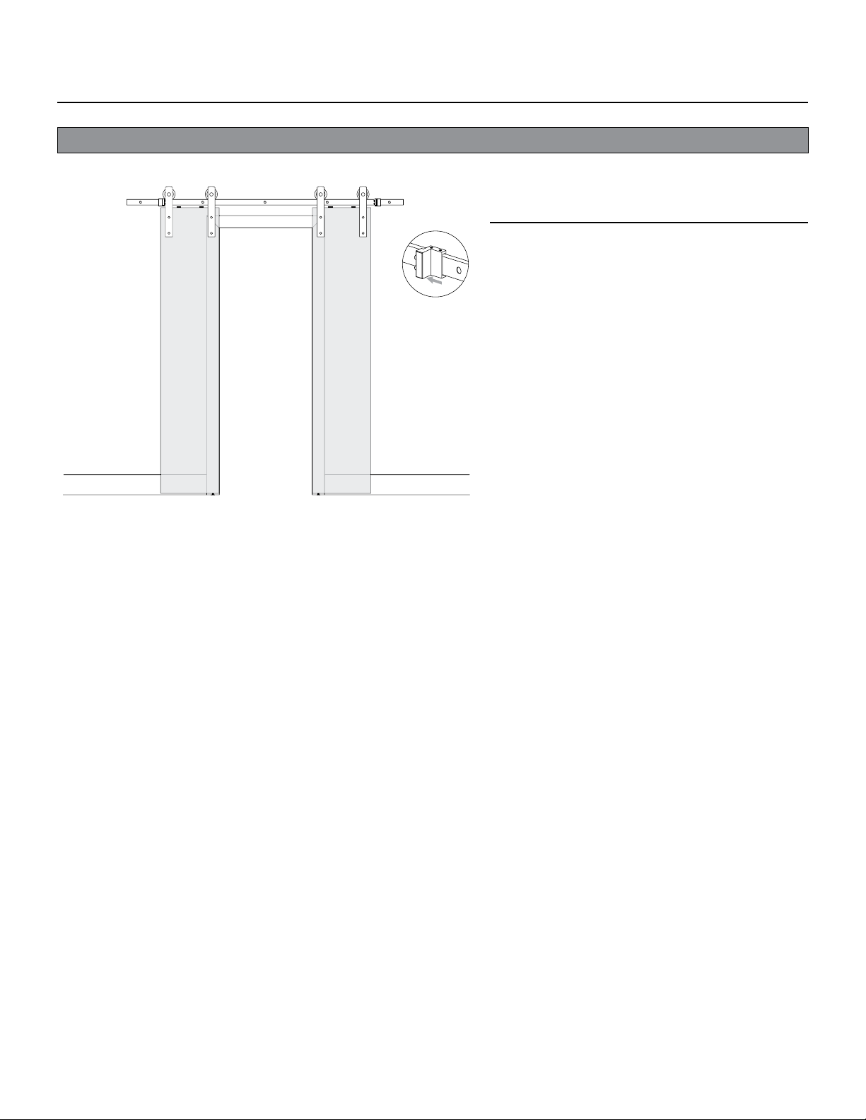
Slide the second door across to the open position and with the door in the ideal
location, secure the stopper in place as shown to complete the installation.
Desliza la segunda puerta a lo largo de la posición abierta y, con la puerta
en la posición ideal, asegura el tope en su lugar, como se muestra, para
completar la instalación.
07B
 Loading...