

Winplus RFOFFROAD Users Manual
TM
TERRA PRO
35 CM (14 IN) LIGHT BAR
WITH UNIVERSAL MOUNTING KIT & WIRELESS CONTROLLER
ITM./ART. 1331173
WP ITM. LM57170
Care & Use Instructions
Important, retain for future reference:
Read carefully

TABLE OF CONTENTS
1. Warning ...................................................................................................................................................... 3
2. Package Contents ..................................................................................................................................... 4
3. Product Specications .............................................................................................................................. 5
4. Status Light Indication ............................................................................................................................... 5
5. Installation Guide ...................................................................................................................................... 6
6. Troubleshooting ......................................................................................................................................... 9
7. Warranty ..................................................................................................................................................... 9
8. FCC Compliance Statement .....................................................................................................................11

WARNING
IMPORTANT SAFETY INSTRUCTIONS
1. SAVE THESE INSTRUCTIONS– This manual contains important safety and operating instructions.
2. Before using this product, read all instructions and cautionary markings.
3. Do not expose the switch controller to rain, moisture, or snow.
4. Use of an attachment not recommended or sold by the manufacturer may result in a risk of re, electric
shock, or injury to persons.
5. Do not operate with damaged light bar or switch controller – replace it immediately.
6. Do not operate light bar or switch controller if it has received a sharp blow, been dropped, or otherwise
damaged in any way; take it to a qualied serviceperson.
7. Do not disassemble light bar or switch controller; take it to a qualied serviceperson when service or
repair is required. Incorrect reassembly may result in a risk of electric shock or re.
8. To reduce risk of electric shock, unplug light bar or switch controller before attempting any maintenance
or cleaning. Turning off controls will not reduce this risk.
CAUTIONS
Check your state or provincial laws before installing. Vehicle owner must comply with all applicable laws.
This product is intended solely for off road purposes. Manufacturer and Seller assume no liability for
installation or use, which are solely the responsibility of the purchaser. This product is not DOT approved
and is designed and intended for off road uses only.
1. Do not install or use product if it, in any way, impairs the safe operation of your vehicle.
2. Follow manufacturer’s instructions to ensure the product is properly and safely installed.
3. Check your state or provincial laws before installing. Vehicle owner must comply with all applicable laws.
4. This product is intended solely for off road purposes. Manufacturer and Seller assume no liability for
installation or use, which are solely the responsibility of the purchaser.
5. This product is not DOT approved and is designed and intended for off road uses only.
6. The Manufacturer and Seller are not responsible or liable for consequential, incidental, or indirect
damages, whether to person or property, resulting from the installation or improper use of this product.
3MTM is a trademark of 3M Company.
3

PACKAGE CONTENTS
3M 3M 3M 3M
3M 3M 3M 3M
3M 3M 3M 3M
3M 3M 3M 3M
3M 3M 3M 3M
1 x 35 cm (14 in) Light Bar
1 × Allen Key 4 × Zip Tie
Tools needed (not included)
4
Screwdriver
2 x Universal
Mounting Bracket A
WrenchPhillips Head
1 × Hub Controller
with easy battery connector
4 x Set of M6 Screw
with Nut, Spring Washer
and Flat Washer
2 x Universal
Mounting Bracket B
Power Drill
1 × Switch
Controller
(OFFROAD RF SWITCH CONTROLLER)
1 × 3M™ Double-sided
Tape for Hub Controller
15/64 in (6mm)
Drill Bit

PRODUCT SPECIFICATIONS
Working voltage: DC 12V Only
Transmission distance: 30 ft (9.14 m) (no obstacle)
Frequency band: 2.4 GHz
Watt: 36W
LEDs: 12 × Super White LED
Raw Lumens: 6000
Effective Lumens: 2500
Weatherproof Light: IP67 Rated (Light bar only)
Weight: 1.4 lb / 0.63 kg
Maximum amperage draw: 3A
Replacement Fuse: 5A
STATUS LIGHT INDICATION
Device LED Light Indication Device Status
Hub Controller Rapid ashing
Slow ashing
Switch Controller Rapid ashing
Slow ashing
Pairing
Paired
Pairing
Paired
5
INSTALLATION GUIDE
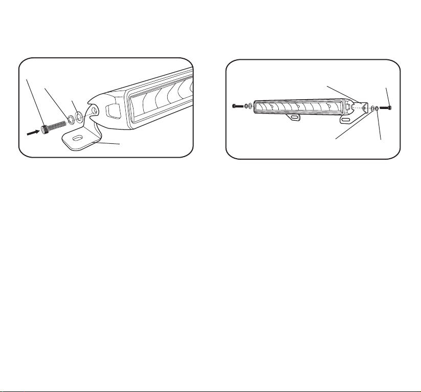
1) INSTALLING THE LIGHT BAR
Universal Mounting Bracket A
M6 Screw
Spring Washer
Flat Washer
Universal Mounting
Bracket A
Universal Mounting Bracket B
Universal
Mounting Bracket B
Flat Washer
M6 Screw
Spring Washer
Hardware:
• Universal Mounting Brackets A or B
• 2 sets of M6 Screw with Nut, Spring Washer and Flat Washer
• 2 sets of M6 Screw with Spring Washer and Flat Washer
Tools Required:
• Power Drill and 15/64 in (6mm) Drill Bit (not included)
• Wrench (not included)
• Allen key
• Attach the Universal Mounting Brackets to A or B to the Light Bar and secure with M6 Screw, Spring
Washer and Flat Washer. Tighten the screw with Allen key.
• Choose a suitable mounting location for the Light Bar, preferably on the front bumper. Make sure the
location is strong enough to hold the Light Bar.
• Mark two holes for the Universal Mounting Brackets for a precise installation. Make sure nothing
beneath will be damaged after the holes are drilled.
• Drill the holes with a 15/64 inch (6mm) Drill Bit.
• Mount the Light Bar with the provided hardware.
• You can adjust the Light Bar’s beam angle by loosening the M6 Screw. Be sure not to over-tighten the
screw after the adjustment.
NOTE: INSTALL LIGHT BAR ON METAL OR DURABLE MATERIALS ONLY.
6
2)
3M 3M 3M 3M
3M 3M 3M 3M
3M 3M 3M 3M
3M 3M 3M 3M
3M 3M 3M 3M
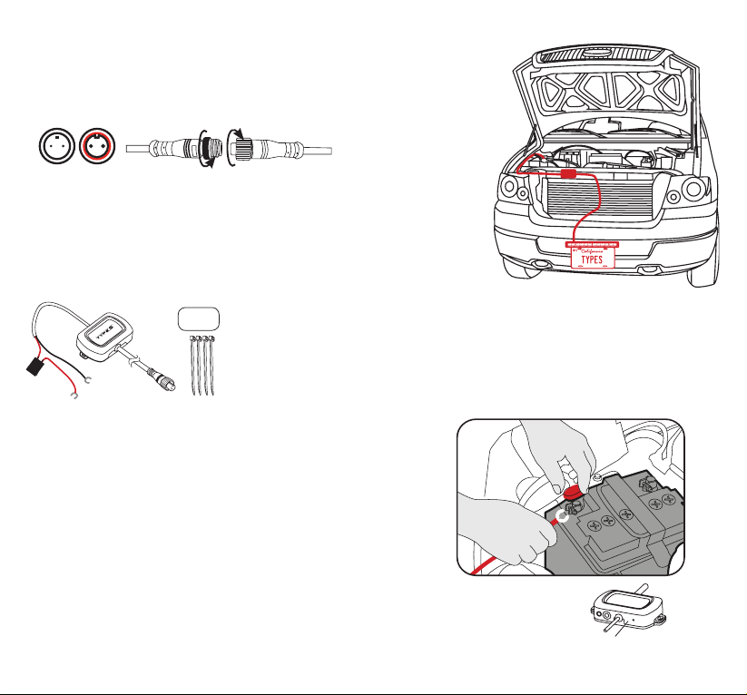
CONNECT THE LIGHT TO THE HUB CONTROLLER
-
Connect the Light Bar cable with the Hub Controller cable. Make sure the
connectors are securely fastened and route cables away from engine. The
connectors are directional, make sure to connect to the correct position and
fasten each end of the cap.
-
Position the Hub Controller away from the car engine. Make sure to avoid
placing the Hub Controller or cables near any extremely HOT location or
next to the car’s engine. Use 3M™ double sided tape or zip ties to secure
the Hub Controller to any at surface if needed. The best location for the
Hub Controller will be inside the front grill if possible.
3) INSTALLING THE HUB CONTROLLER:
WARNING: DO NOT mix up the cables or allow the
metal ends to touch together because this may damage
the battery, charging system and/or electronics on a
vehicle. When installing, please make sure your engine
is not running.
•
For use with 12V power only
• Hub Controller hardwire cables are color-coded, RED for POSITIVE
(+) and BLACK for NEGATIVE (-).
- Connect the RED cable to the POSITIVE (+) battery clamp as
illustrated. The POSITIVE battery post will be slightly larger than
the NEGATIVE post, and will be marked with a PLUS (+) sign.
There may also be a RED protective cover over the positive
battery post.
- Connect the BLACK cable to the NEGATIVE (-) battery clamp
as illustrated. The NEGATIVE will be marked with a MINUS (-)
sign. There may also be a BLACK plastic protective cover over
the negative battery post.
NOTE: After connecting the Hub Controller to the car battery, the
Blue LED indicator will ash. If the LED indicator does not ash once
connected, please check your power connections.
Power Indicator
7
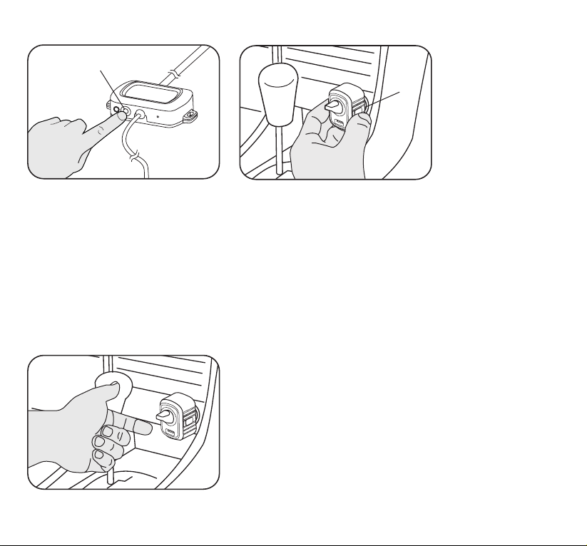
4) PAIRING
Pairing Button
Pairing
Button
Fig.1
Fig.2
• The unit is ready to use without additional pairing. However the Switch Controller can control
additional Type S Light Bars via pairing. One Switch Controller can connect up to 4 Light Bars.
• To pair, press the pair button on the Hub Controller once. (Fig.1) The unit goes into pairing mode for
30 seconds. Plug in the Switch Controller into a 12V car socket, then press and hold the pair button
for 3 seconds. (Fig.2) It will pair with the Hub Controller within 5 seconds.
• Flip the toggle switch on/off to check if the connection is successful. Repeat above steps to pair each
additional Type S Light Bar to the same Switch Controller.
5) PLUG IN SWITCH CONTROLLER
• Plug the Switch Controller into any 12V car socket.
• Flip the toggle switch to turn the Light Bar on/off. The blue LED
indicator will be ashing slowly, indicating it’s on and paired.
• Light Bar will be turned off automatically when the engine shuts off.
Warning: Some vehicles provide constant power to the 12V outlet.
Please remember to unplug the Switch Controller when not in use to
avoid draining of the vehicle battery.
8
 Loading...