

Page 1

Model: BLELED
Bluetooth Module Datasheet
Module
for Lighting kit
BLELED
Document Information
Title
Document type
Document number
Revision and date
Disclosure restriction
1 / 17 SKB360-DA-001,A/4
Module for Lighting kit
Datasheet
SL-18050051
V4.02 15-May-2018
Public
Page 2

Bluetooth Module Datasheet
Model: BLELED
2 / 17
SKB360-DA-001,A/4
This document applicable to the following products:
Product name
Type number
Product status
Module for
Lighting kit
BLELED
Mass Production
Page 3

Bluetooth Module Datasheet
Model: BLELED
3 / 17
SKB360-DA-001,A/4
Contents
1 General Description ................................................................................................................................................4
2 Applications ............................................................................................................................................................4
3 Features ..................................................................................................................................................................5
4 Application Block Diagram .....................................................................................................................................5
5 Interfaces ................................................................................................................................................................6
5.1 Power Supply ...............................................................................................................................................6
5.2 System Function Interfaces..........................................................................................................................6
5.2.1 GPIOs ..................................................................................................................................................6
5.2.2 Two-wire Interface (I2C Compatible) ...................................................................................................6
5.2.3 Flash Program I/Os ..............................................................................................................................7
5.2.4 Serial Peripheral Interface ...................................................................................................................7
5.2.5 UARTs .................................................................................................................................................7
5.2.6 Analog to Digital Converter (ADC).......................................................................................................8
5.2.7 Low Power Comparator (LPCOMP) ....................................................................................................8
5.2.8 Reset ....................................................................................................................................................8
6 Module Specifications .............................................................................................................................................9
7 Module Pinout and Pin Description ...................................................................................................................... 10
7.1 Module Pinout ............................................................................................................................................ 10
7.2 Pin Description ........................................................................................................................................... 11
8 PCB Design Guide ............................................................................................................................................... 12
9 PCB Footprint and Dimensions ............................................................................................................................ 12
10 Electrical Characteristics .................................................................................................................................... 13
10.1 Absolute Maximum Ratings ..................................................................................................................... 13
10.2 Recommended Operation Ratings ........................................................................................................... 14
10.3 Current ..................................................................................................................................................... 14
11 Manufacturing Process Recommendations ....................................................................................................... 14
12 Ordering Information........................................................................................................................................... 15
13 Packaging Specification ..................................................................................................................................... 15
14 FCC/IC Information............................................................................................................................................. 16
15 Revision History .................................................................................................................................................. 17
Page 4
Bluetooth Module Datasheet
Model: BLELED
4 / 17
SKB360-DA-001,A/4
1 General Description
The BLELED is a highly integrated Bluetooth 4.2 BLE module, designed for high data rate, short-range wireless
communication in the 2.4GHz ISM band. The module is based on Nordic nRF518xx radio Transceiver IC, has a
32 bit ARM Cortex-M0 CPU, Flash memory and analog and digital peripherals. The BLELED provides a low
power and ultra-low cost BLE solution for wireless transmission applications.
2 Applications
◆ Computer peripherals and I/O devices
Mouse
Keyboard
Multi-touch trackpad
◆ Interactive entertainment devices
Remote control
3D Glasses
Gaming controller
◆ Personal Area Networks
Health/fitness sensor and monitor devices
Medical devices
Key-fobs + wrist watches
◆ Remote control toys
◆ Beacons
◆ Bluetooth Gateway
◆ Indoor Location
◆ Colourful LED Control
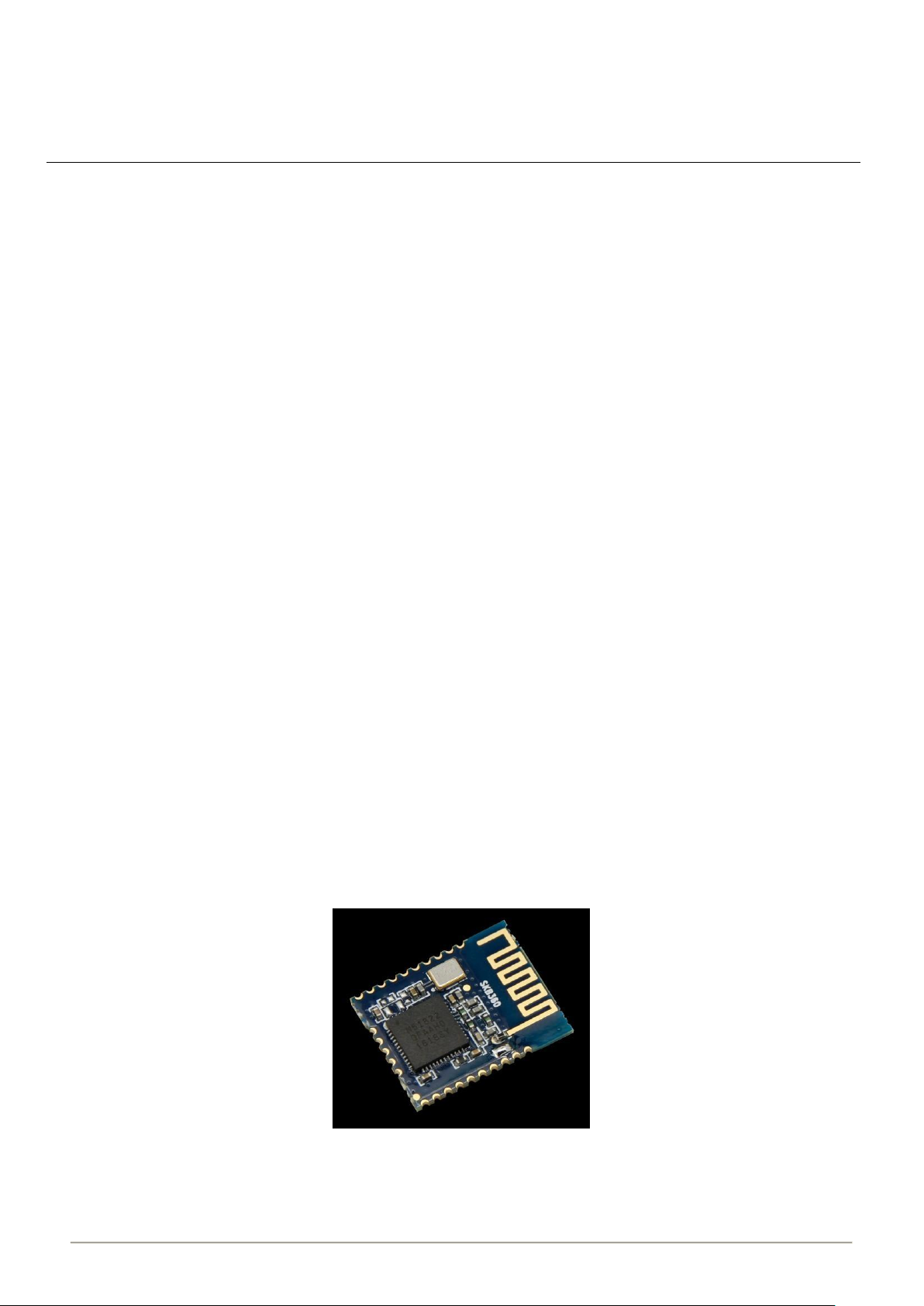
Figure 1: BLELED Top View
Page 5
Bluetooth Module Datasheet
Model: BLELED
5 / 17
SKB360-DA-001,A/4
3 Features
◆ Main Chip: nRF518xx
◆ Bluetooth® 4.2 low energy single-mode protocol stack L2CAP,
ATT, GAP, GATT and SM protocols
Central and Peripheral roles
GATT Client and Server
Full SMP support including MITM and OOB pairing
◆ Data rates up to 1Mbps
◆ 8/9/10 bit ADC-4 configurable channels
◆ 20 General Purpose I/O pins
◆ SPI Master/Slave
◆ Two-wire Master (I2C compatible)
◆ UART (CTS/RTS)
◆ CPU independent Programmable Peripheral Interconnect (PPI)
◆ Quadrature Decoder (QDEC)
◆ AES HW encryption
◆ RoHS compliance (Lead-free)
◆ CE,FCC compliance
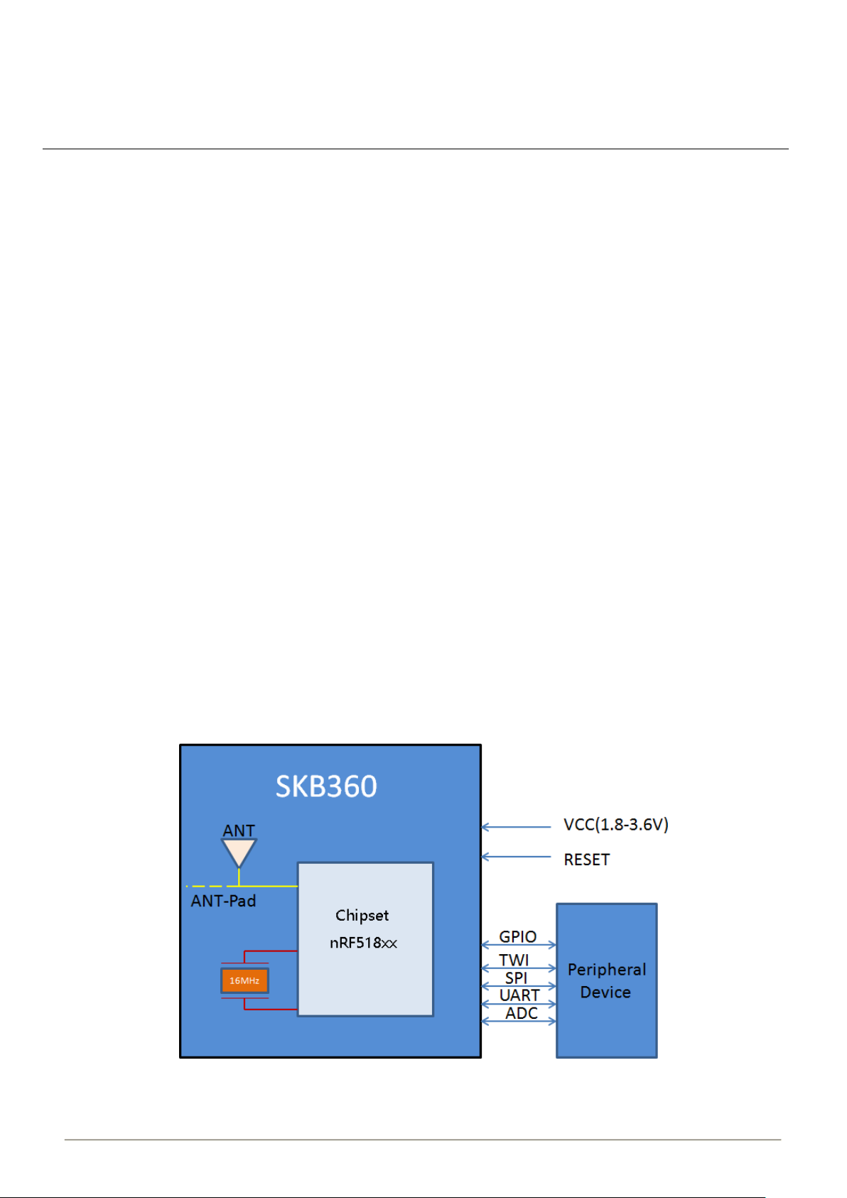
4 Application Block Diagram
Figure 2: BLELED Block Diagram
Page 6

Bluetooth Module Datasheet
Model: BLELED
6 / 17
SKB360-DA-001,A/4
5 Interfaces
5.1 Power Supply
Regulated power for the BLELED is required. The input voltage Vcc range should be 1.8V to 3.6V, current is not
less than 20mA. Suitable decoupling must be provided by external decoupling circuitry (10uF and 0.1uF). It can
reduce the noise from power supply and increase power stability.
5.2 System Function Interfaces
5.2.1 GPIOs
The general purpose I/O is organized as one port with up to 20 I/Os enabling access and control of up to 20 pins
through one port. Each GPIO can be accessed individually with the following user configurable features:
1、Input/output direction
2、Output drive strength
3、Internal pull-up and pull-down resistors
4、Wake-up from high or low level triggers on all pins
5、Trigger interrupt on all pins
6、All pins can be used by the PPI task/event system; the maximum number of pins that can be interfaced through
the PPI at the same time is limited by the number of GPIOTE channels
7、All pins can be individually configured to carry serial interface or quadrature demodulator signals
8、All pins can be configured as PWM signal.
9、There are 4 ADC/LPCOMP input in the 20 I/Os.
5.2.2 Two-wire Interface (I2C Compatible)
The two-wire interface can communicate with a bi-directional wired-AND bus with two lines (SCL, SDA). The
protocol makes it possible to interconnect up to 127 individually addressable devices. The interface is capable of
clock stretching, supporting data rates of 100 kbps and 400 kbps. The module has 2 TWI ports and they
properties like following table.
Instance
Master/Slave
TWI0
Master
TWI1
Master
Table5-1: TWI Pin Share Scheme
Page 7

Bluetooth Module Datasheet
Model: BLELED
7 / 17
SKB360-DA-001,A/4
Note:I2C:Inter-Integrated Circuit
5.2.3 Flash Program I/Os
The module has two programmer pins, respectively SWDCLK pin and SWDIO pin. The two pin Serial Wire Debug
(SWD) interface provided as a part of the Debug Access Port (DAP) offers a flexible and powerful mechanism for
non-intrusive debugging of program code. Breakpoints and single stepping are part of this support.
SWDIO can also be used as system reset pin, the system reset pin is active low.
5.2.4 Serial Peripheral Interface
The SPI interfaces enable full duplex synchronous communication between devices. They support a three-wire
(SCK, MISO, MOSI) bi-directional bus with fast data transfers. The SPI Master can communicate with multiple
slaves using individual chip select signals for each of the slave devices attached to a bus. Control of chip select
signals is left to the application through use of GPIO signals. SPI Master has double buffered I/O data. The SPI
Slave includes EasyDMA for data transfer directly to and from RAM allowing Slave data transfers to occur while
the CPU is IDLE. The GPIOs are used for each SPI interface line can be chosen from any GPIOs on the device
and configed independently. This enables great flexibility in device pinout and efficient use of printed circuit board
space and signal routing.
The SPI peripheral support SPI mode 0,1,2,and 3.The module have 3 SPI ports and theirs they properties are as
below:
Table5-2: SPI Properties
5.2.5 UARTs
The Universal Asynchronous Receiver/Transmitter offers fast, full-duplex, asynchronous serial communication
with built-in flow control (CTS, RTS), support in hardware up to 1 Mbps baud. Parity checking is supported.
The default P0.08 is UART_TX, P0.09 is UART_RX. Support the following baudrate in bps unit:
1200/2400/4800/9600/14400/19200/28800/38400/57600/76800/115200.
Instance
Master/Slave
SPI0
Master
SPI1
Master
SPIS1
Slave
Page 8

Model: BLELED
Bluetooth Module Datasheet
BLELED Pin
Number
16 P0.08 UART_TX
17 P0.09 UART_RX
Table5-3: UART Pin Share Scheme
Pin Name UART Pin Share
UART(For Debug)
Note: The GPIOs are used for each SPI/TWI/UART interface line can be chosen from any GPIOs on the device
and configed independently.
5.2.6 Analog to Digital Converter (ADC)
The 10 bit incremental Analog to Digital Converter (ADC) enables sampling of up to 8 external signals through a
front-end multiplexer. The ADC has configurable input and reference prescaling, and sample resolution (8, 9, and
10 bit).
Note: The ADC module uses the same analog inputs as the LPCOMP module. Only one of the modules can be
enabled at the same time.
BLELED Pin
Number
12
13
14
15
Pin Number Description
P0.01
P0.02
P0.03
P0.04
Table5-4: ADC Pins
Digital I/O; Analog input 2
Digital I/O;A nalog input 3
Digital I/O; Analog input 4
Digital I/O; Analog input 5
5.2.7 Low Power Comparator (LPCOMP)
In System ON, the block can generate separate events on rising and falling edges of a signal, or sample the
current state of the pin as being above or below the threshold. The block can be configured to use any of the
analog inputs on the device. Additionally, the low power comparator can be used as an analog wakeup source
from System OFF or System ON. The comparator threshold can be programmed to a range of fractions of the
supply voltage.
5.2.8 Reset
The reset pin of the BLELED module is in the internal pull-high state , when the reset pin of the
8 / 17 SKB360-DA-001,A/4
Page 9

Bluetooth Module Datasheet
Model: BLELED
9 / 17
SKB360-DA-001,A/4
module is input to a low level , the module will be automatically reset .After the reset pin is used , the parameters
of the current setting will not be reserved .
6 Module Specifications
Hardware Features
Model
BLELED
Antenna Type
PCB Antenna
Chipset Solution
nRF518xx
Voltage
1.8V~3.6V
Dimension(L×W×H)
17.4×13.7×1.9 mm
Wireless Features
Wireless Standards
Bluetooth ® 4.2
Frequency Range
2400MHz---2483.5MHz
Data Rates
1Mbps
Modulation Technique
GFSK Modulation
Wireless Security
AES HW Encryption
Transmit Power
Tx Power -20 to +4 dBm in 4 dB Steps
Work Mode
Central/Peripheral
Others
Certification
RoHS, FCC, CE
Environment
Operating Temperature: -25℃~75℃
Storage Temperature: -40℃~85℃
Operating Humidity: 10%~90% Non-condensing
Storage Humidity: 5%~90% Non-condensing
Page 10
Bluetooth Module Datasheet
Model: BLELED
10 / 17
SKB360-DA-001,A/4
7 Module Pinout and Pin Description
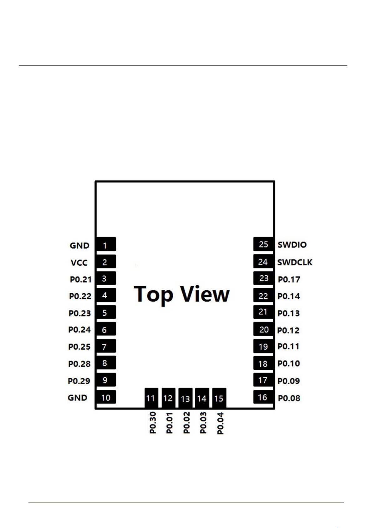
7.1 Module Pinout
Figure 3: BLELED Module Pinout
Page 11

Bluetooth Module Datasheet
Model: BLELED
11 / 17
SKB360-DA-001,A/4
7.2 Pin Description
Pin No.
Pin Name
Description
Remark
1
GND
Ground
2
VCC
Main Power Supply
1.8V to 3.6V
3
P0.21
General Purpose I/O
Digital I/O
4
P0.22
General Purpose I/O
Digital I/O
5
P0.23
General Purpose I/O
Digital I/O
6
P0.24
General Purpose I/O
Digital I/O
7
P0.25
General Purpose I/O
Digital I/O
8
P0.28
General Purpose I/O
Digital I/O
9
P0.29
General Purpose I/O
Digital I/O
10
GND
Ground
11
P0.30
General Purpose I/O
Digital I/O
12
P0.01
Digital I/O; Analog input
ADC/LPCOMP input 2
13
P0.02
Digital I/O; Analog input
ADC/LPCOMP input 3
14
P0.03
Digital I/O; Analog input
ADC/LPCOMP input 4
15
P0.04
Digital I/O; Analog input
ADC/LPCOMP input 5
16
P0.08
General Purpose I/O
Default UART TX
17
P0.09
General Purpose I/O
Default UART RX
18
P0.10
General Purpose I/O
Digital I/O
19
P0.11
General Purpose I/O
Digital I/O
20
P0.12
General Purpose I/O
Digital I/O
21
P0.13
General Purpose I/O
Digital I/O
22
P0.14
General Purpose I/O
Digital I/O
23
P0.17
General Purpose I/O
Digital I/O
24
SWDCLK
Hardware debug and Flash
program I/O
Digital input
25
SWDIO/n RESET
Hardware Debug and Flash
Program I/O; System Reset
(Active low)
Digital I/O
Page 12
Bluetooth Module Datasheet
Model: BLELED
12 / 17
SKB360-DA-001,A/4
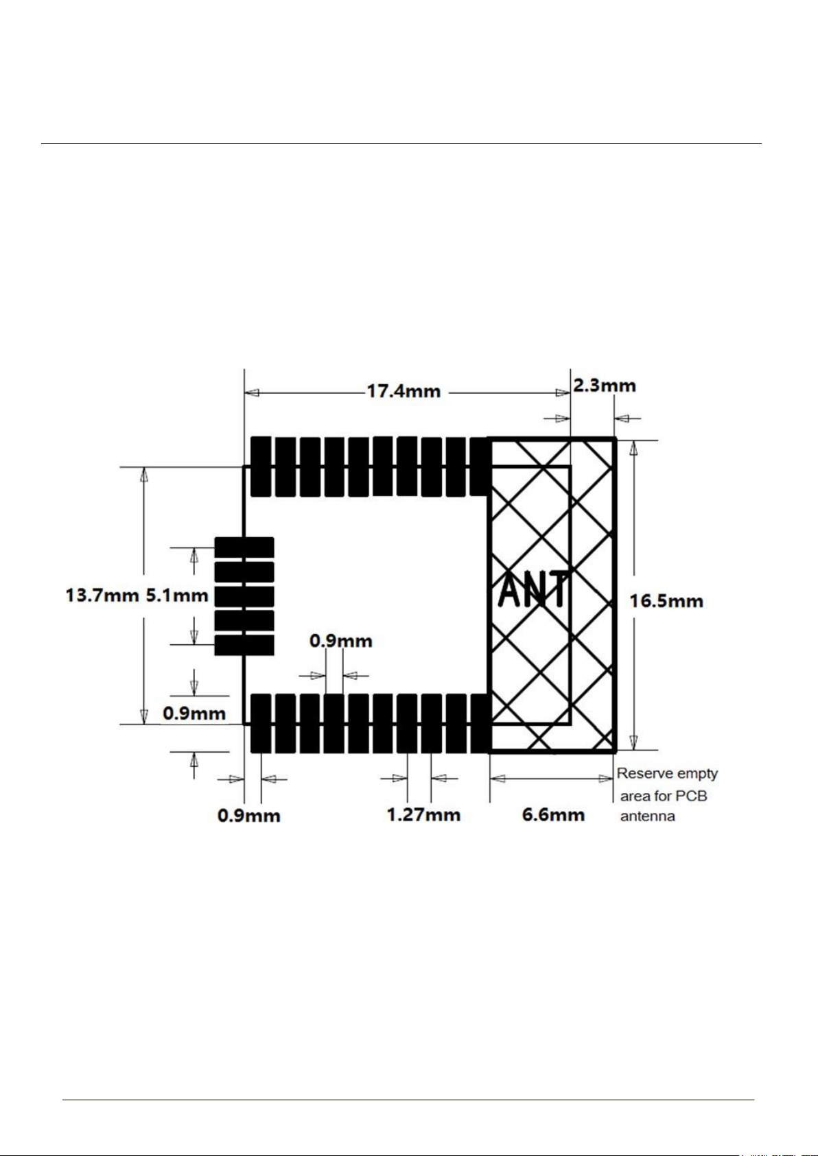
8 PCB Design Guide
Please reserve empty area for PCB antenna when you are going to design a board, the empty range
device’s minimum size :16.5*6.6mm , please kindly check the “PCB footprint and Dimensions” for reference.
9 PCB Footprint and Dimensions
Figure 4: BLELED Recommended PCB Footprint
Page 13

Bluetooth Module Datasheet
Model: BLELED
13 / 17
SKB360-DA-001,A/4
10 Electrical Characteristics
10.1 Absolute Maximum Ratings
Parameter
Condition
Min.
Typ.
Max.
Unit
Storage Temperature Range
-40 85
°C
ESD Protection
VESD
/ 4000
V
Supply Voltage
VCC
-0.3
3.9
V
Voltage On Any I/O Pin
-0.3
3.63
V
Table10-1: Absolute Maximum Ratings
Note: Absolute maximum ratings are stress ratings only, and functional operation at the maxims is not
guaranteed. Stress beyond the limits specified in this table may affect device reliability or cause permanent
damage to the device. For functional operating conditions, refer to the operating conditions tables as follow.
*BLELED series modules are Electrostatic Sensitive Devices and require special precautions while handling.
ESD precautions
The BLELED series modules contain highly sensitive electronic circuitry and are Electrostatic Sensitive
Devices (ESD). Handling the BLELED series modules without proper ESD protection may destroy or
damage them permanently.
The BLELED series modules are electrostatic sensitive devices (ESD) and require special ESD
precautions typically applied to ESD sensitive components. Proper ESD handling and packaging
procedures must be applied throughout the processing, handling, transportation and operation of any
application that incorporates the BLELED series module. Don’t touch the module by hand or solder with
non-anti-static soldering iron to avoid damage to the mode.
Page 14

Bluetooth Module Datasheet
Model: BLELED
14 / 17
SKB360-DA-001,A/4
10.2 Recommended Operation Ratings
Parameter
Symbol
Min.
Typ.
Max.
Unit
Extended Temp. Range
TA
-25 75
ºC
Power Supply
VCC
1.8
3.3
3.6 V Input Low Voltage
VIL
0 1 V Input High Voltage
VIH
2.3 3.9
V
10.3 Current
Table10-2: Operating Conditions
System State
TX Peak
@0dBm
RX Peak
Advertise Interval
@100ms (0dBm)(avg)
Sleep Mode
(avg)
Idle Mode
(avg)
Current
(peak)@3V
10.5 mA
13 mA 270uA
0.28uA
2.43uA
Table10-3: Power Consumption in Different States
11 Manufacturing Process Recommendations
Figure 5: BLELED Typical Lead-free Soldering Profile
Note:The final re-flow soldering temperature map chosen at the factory depends on additional external factors,
for example, choice of soldering paste, size, thickness and properties of the module`s baseboard etc.
Page 15
Bluetooth Module Datasheet
Model: BLELED
15 / 17
SKB360-DA-001,A/4
Exceeding the maximum soldering temperature in the recommended soldering profile may permanently damage
the module.
12 Ordering Information
Module No.
Type number
Chipset
Certification
BLELED
09192
nRF51822
RoHS, FCC, CE
BLELED
0919204
nRF51802
RoHS, FCC, CE
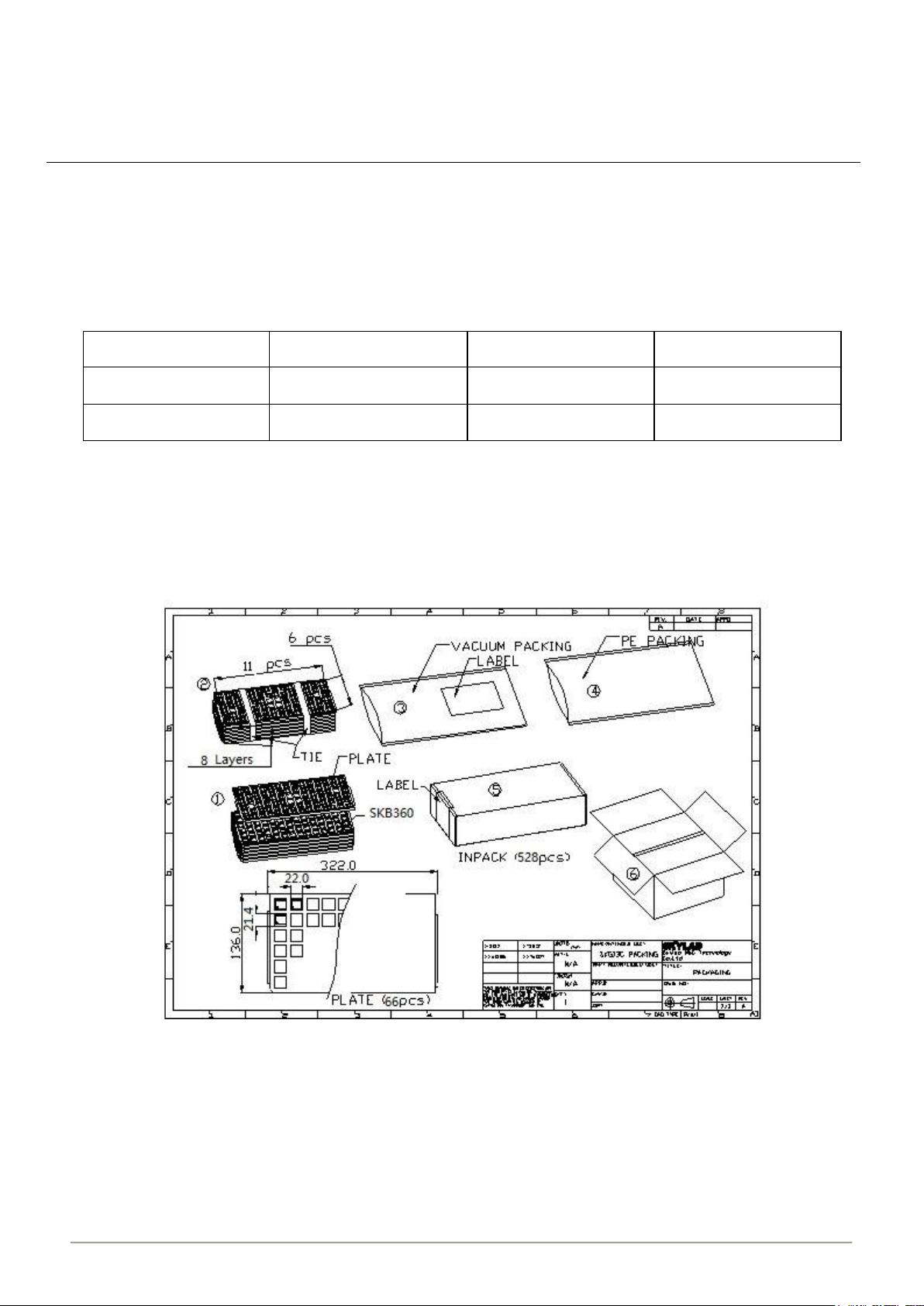
13 Packaging Specification
BLELED modules are put into tray and 528 units per tray. Each tray is ‘dry’ and vacuum packaging.
Figure 6: BLELED Packaging
Page 16

Bluetooth Module Datasheet
Model: BLELED
16 / 17
SKB360-DA-001,A/4
14. FCC Information
This device complies with Part 15 of the FCC Rules.
Operation is subject to the following two conditions: (1) this device may not cause harmful interference, and (2) this
device must accept any interference received, including interference that may cause undesired operation.
THE MANUFACTURER IS NOT RESPONSIBLE FOR ANY RADIO OR TV INTERFERENCE CAUSED BY
UNAUTHORIZED MODIFICATIONS OR CHANGE TO THIS EQUIPMENT. SUCH MODIFICATIONS OR CHANGE
COULD VOID THE USER’S AUTHORITY TO OPERATE THE EQUIPMENT.
This equipment has been tested and found to comply with the limits for a Class B digital device, pursuant to part 15
of the FCC Rules. These limits are designed to provide reasonable protection against harmful interference in a
residential installation. This equipment generates, uses and can radiate radio frequency energy and, if not installed
and used in accordance with the instructions, may cause harmful interference to radio communications. However,
there is no guarantee that interference will not occur in a particular installation. If this equipment does cause
harmful interference to radio or television reception, which can be determined by turning the equipment off and on,
the user is encouraged to try to correct the interference by one or more of the following measures:
-- Reorient or relocate the receiving antenna.
-- Increase the separation between the equipment and receiver.
-- Increase the separation between the equipment and receiver.
-- Consult the dealer or an experienced radio/TV technician for help.
This equipment complies with FCC RF radiation exposure limits set forth for an uncontrolled environment.
To satisfy FCC exterior labeling requirements, the following text must be placed on the exterior of the end product
“Contains Transmitter module FCC ID: WUI-BLELED”
The modular must be installed in the host that assign by
Company name: Winplus Co., Ltd.
Product/PMN: Exterior Trim LED
Model no./HVIN: LM57485
if other host types used would need further evaluation and possible C2PC if they are not significantly similar to the
one tested.
IC Information
-English:
1. This device complies with Industry Canada RSS standard(s). Operation is subject to the following two conditions:
(1) this device may not cause interference, and (2) this device must accept any interference, including interference
that may cause undesired operation of the device.
2. Changes or modifications not expressly approved by the party responsible for compliance could void the user's
authority to operate the equipment.
This equipment complies with ISED RF radiation exposure limits set forth for an uncontrolled environment.
-French:
Leprésent appareil est conforme aux CNR d'Industrie Canada applicable aux appareils radio
Exempts de licence. L'exploitation est autorisée aux deux conditions suivantes :
(1) l'appareil ne doit pas produire de brouillage, et (2) l'utilisateur de l'appareil doit accepter tout brouillage
radioélectrique subi, meme si le brouillage est susceptible d'en compromettre le fonctionnement."
Cet appareil est conforme aux limitesd'exposition de rayonnement RF ISEDC établiespour un environnement non
contrôlé.
Pour satisfaire la ISED extérieur étiquetage, le texte suivant doit être placéàl’extérieur du produit final “Contains
émetteur module IC:7297A-BLELED”.
The modular must be installed in the host that assign by
Le modulaire doit être installé dans l'hôte assigné par
Nom de la compagnie: Winplus Co., Ltd.
Produit/PMN: Exterior Trim LED
Modèle no./HVIN: LM57485
if other host types used would need further evaluation and possible C2PC if they are not significantly similar to the
one tested.
si d'autres types d'hôtes utilisés nécessiteraient une évaluation plus poussée et un C2PC possible s'ils ne sont pas
significativement similaires à celui testé
Page 17

Bluetooth Module Datasheet
Model: BLELED
17 / 17
SKB360-DA-001,A/4
14 Revision History
Revision
Description
Approved
Date
V1.01
Initial Release
Sunny
20140611
V2.01
Upgrade Hardware
Sunny
20150117
V2.02
Add AT Instruction
Sunny
20150528
V2.03
Upgrade hardware
Hogan
20160611
V3.01
Upgrade format
Hogan
20161211
V3.02
Upgrade product image
Hogan
20170504
V3.03
Update certification information
George
20170831
V4.01
Add order information
George
20180209
V4.02
Add part number information
George
20180515
 Loading...