

Page 1
Page 2
1
/ 71
Contents
1. Product overview ........................................................................................................................................ 3
2. Product specifications .................................................................................................................................3
Figure 2- 1 EXV2080 product specification sheet ...........................................................................................4
3. Packing list ..................................................................................................................................................4
4. Structure and function .................................................................................................................................5
5. Main interface description ...........................................................................................................................6
6. Test LCD module interface .........................................................................................................................6
6.1 LCD module parameter selection.................................................................................................... 7
6.2 Parameter setting .............................................................................................................................. 7
6.3 Example of measuring LCD module .................................................................................................8
6.3.1 Connection description........................................................................................................... 8
6.3.2 Connection between EXV2080 and LCD module..................................................................9
6.3.3 Image comparing of test case .............................................................................................. 10
7. The UI of testing TV motherboard ............................................................................................................11
7.1 Enter the UI of testing TV motherboard ..........................................................................................11
7.2 Connecting TV motherboard to EXV2080 ......................................................................................... 12
7.3 Brief introduction to the function of testing TV motherboard ..........................................................14
8. Detailed steps of test LCD module ...........................................................................................................15
8.1 Connect to 2K-LVDS LCD module ................................................................................................. 16
8.1.1 Types of HD LVDS Cable .....................................................................................................17
8.1.2 Selection of HD LVDS Cable ................................................................................................17
8.1.3 Example of connecting HD LVDS LCD module Cable ........................................................ 18
8.1.4 Types of FHD LVDS Cable ...................................................................................................20
8.1.5 FHD LVDS Cable sequence .................................................................................................21
8.1.6 Connect to FHD LVDS dual LCD Cable ...............................................................................22
8.1.7 Connect to LVDS signal panel ..............................................................................................23
8.2 Connect to 4K-VBY1 LCD module ..................................................................................................25
8.2.1 VBY1 LCD module with General cable sequence ............................................................. 25
8.2.2 Special 4K-VBY1 Cable sequence of CSOT or Samsung...................................................26
8.2.3 Connect to 4K-VBY1 LCD module with CSOT cable sequence or Samsung cable
sequence ........................................................................................................................................27
8.2.4 Connect to 4K-VBY1 dual cable LCD module ..................................................................... 28
8.3 Instruction for Directly Connected Board T2 .................................................................................. 28
8.4 LCD module parameters setting .....................................................................................................29
8.4.1 Parameters Setting of LCD module with LVDS signal.........................................................29
8.4.2 Parameters Setting of LCD module with VBY1 signal ........................................................30
8.5 Possible reasons why the tested Panel is not displayed ............................................................... 31
8.6 Test panel convert-boards of other special cable sequence......................................................... 31
9. Motherboard test steps .............................................................................................................................31
9.1 Quick operation guide ..................................................................................................................... 31
9.2 Signal Type Judgment ................................................................................................................... 33
9.2.1 LVDS Single LCD module Cable motherboard....................................................................33
9.2.2 LVDS Dual LCD module Cable Motherboard ...................................................................... 34
9.2.3 MINILVDS motherboard ..................................................................................................... 34
9.2.4 MINILVDS motherboard Cable sequence judgment ............................................................35
9.2.5 Connect to MINI LVDS motherboard ................................................................................... 36
9.5.6 VBY1 Single LCD module Cable motherboard ....................................................................37
9.5.7 VBY1 Dual LCD module Cable motherboard .......................................................................37
9.6 Judgment of Motherboard Cable sequence and selection of convert-board .................................38
9.6.1 The convert-boards of test motherboard ..............................................................................38
9.6.2 VBY1 Cable sequence and connection with convert-board ................................................ 38
9.6.3 Connection of VBY1 general Cable sequence and CSOT Cable sequence ...................... 39
9.6.4 Connection of VBY1 Dual LCD module Cable motherboard ...............................................41
9.6.5 LVDS Cable sequence and connection with convert-board ................................................41
9.6.6 Connection between HD LVDS Cable sequence and convert-board ..................................42
9.6.7 Connection FHD LVDS Cable sequence and convert-board .............................................. 44
10. Frequently asked questions and answers ............................................................................................ 45
10.1 Reasons for no display when testing LCD module ...................................................................... 45
Page 3
2
/ 71
10.2 Reasons for no display when testing TV motherboard ................................................................ 45
11. Test Notebook EDP LCD module ......................................................................................................... 45
11.1 What is EDP LCD module .............................................................................................................45
11.2 Features of test EDP LCD module with EXV2080 ....................................................................... 46
11.3 Quick operation guide ................................................................................................................... 46
11.4 Convert-board and LCD module Cable for EDP LCD module test..............................................47
11.5 Judge EDP LCD module ...............................................................................................................49
11.6 Judge EDP Cable sequence .........................................................................................................52
11.7 Connection between convert-board E1 and EXV2080 ................................................................ 53
11.8 Connection between EXV2080 and EDP LCD module ................................................................54
11.9 Enter the EDP LCD module test mode of EXV2080 .................................................................... 54
11.10 Setting LCD module parameters................................................................................................ 56
11.11 Test case ..................................................................................................................................... 56
12. Appendix ................................................................................................................................................ 59
12.1 Appendix A LCD module parameter search in LCD module measurement ................................59
12.2 Appendix B how to distinguish 51 pin LVDS motherboard from VBY1 motherboard ..................60
12.3 Appendix C List of interfaces for testing MINILVDS motherboard .............................................61
12.4 Appendix D test LETV 4K motherboard ....................................................................................... 62
12.5 Appendix E Single clock mode when testing the FHD LVDS motherboard ................................ 63
12.5.1What is a single clock FHD LVDS motherboard................................................................. 63
12.5.2 Test method of single clock FHD LVDS motherboard .......................................................63
12.6 Appendix F Convert-boards with special Cable sequence .......................................................... 64
12.6.1 Convert-board for testing LCD module with special Cable sequence ..............................64
Convert-board P4 with Double Cable LVDS Samsung Cable sequence (left power supply) ......64
12.6.2 Convert-board for testing motherboard with special Cable sequence .............................. 65
12.6.3 Convert-board B5 for testing Samsung VBY1 Cable sequence motherboard ..................66
12.7 Instruction for use of Convert-board A1.......................................................................................66
12.7.1 General Description: .......................................................................................................... 66
12.7.2 The method of connecting Convert-board A1 ....................................................................68
12.7.3 Test TV LCD or OLED panel by Convert-board A1...........................................................71
Page 4
3
/ 71
1. Product overview
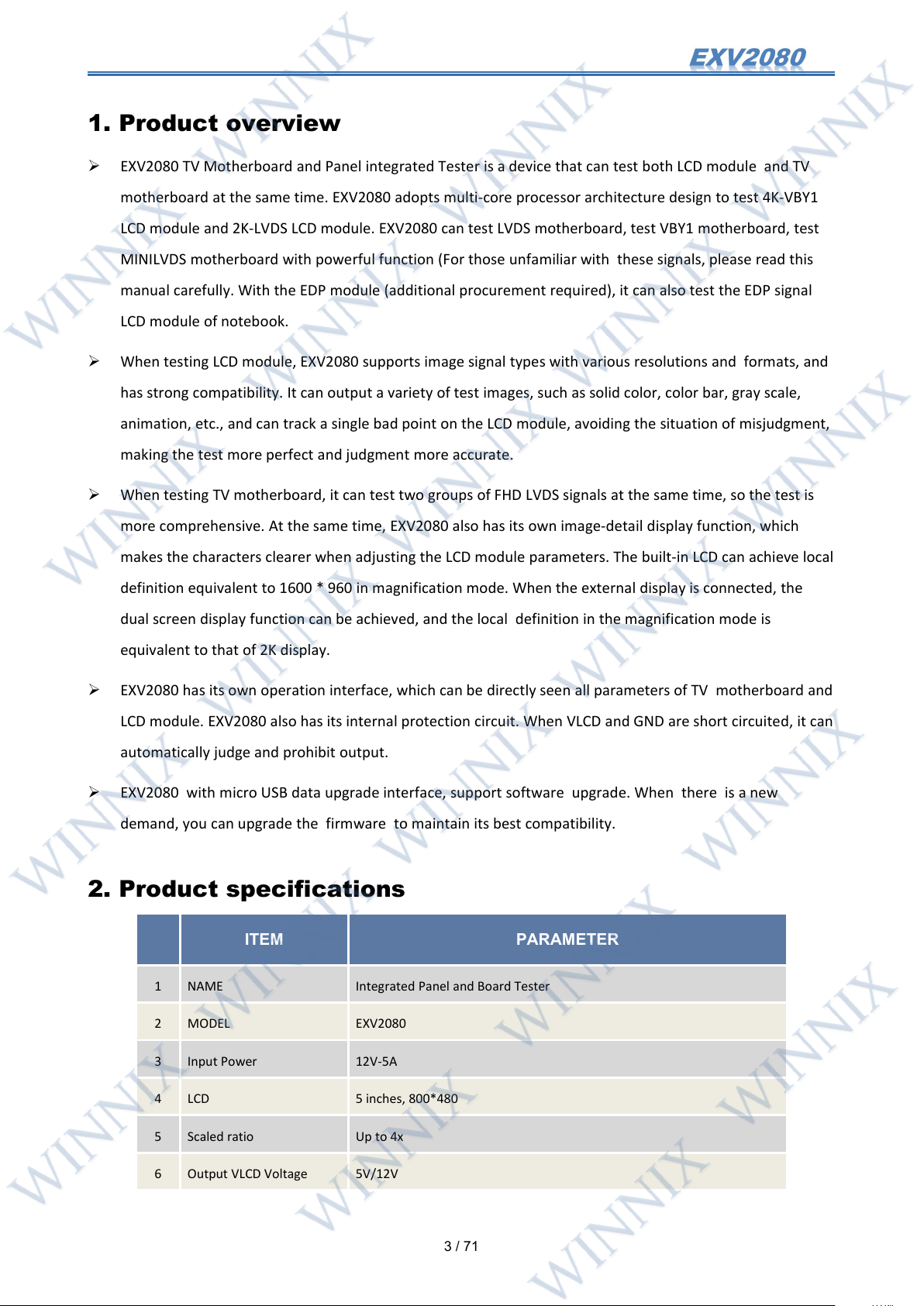
ITEM
PARAMETER
1
NAME
Integrated Panel and Board Tester
2
MODEL
EXV2080
3
Input Power
12V-5A
4
LCD
5 inches, 800*480
5
Scaled ratio
Up to 4x
6
Output VLCD Voltage
5V/12V
EXV2080 TV Motherboard and Panel integrated Tester is a device that can test both LCD module and TV
motherboard at the same time. EXV2080 adopts multi-core processor architecture design to test 4K-VBY1
LCD module and 2K-LVDS LCD module. EXV2080 can test LVDS motherboard, test VBY1 motherboard, test
MINILVDS motherboard with powerful function (For those unfamiliar with these signals, please read this
manual carefully. With the EDP module (additional procurement required), it can also test the EDP signal
LCD module of notebook.
When testing LCD module, EXV2080 supports image signal types with various resolutions and formats, and
has strong compatibility. It can output a variety of test images, such as solid color, color bar, gray scale,
animation, etc., and can track a single bad point on the LCD module, avoiding the situation of misjudgment,
making the test more perfect and judgment more accurate.
When testing TV motherboard, it can test two groups of FHD LVDS signals at the same time, so the test is
more comprehensive. At the same time, EXV2080 also has its own image-detail display function, which
makes the characters clearer when adjusting the LCD module parameters. The built-in LCD can achieve local
definition equivalent to 1600 * 960 in magnification mode. When the external display is connected, the
dual screen display function can be achieved, and the local definition in the magnification mode is
equivalent to that of 2K display.
EXV2080 has its own operation interface, which can be directly seen all parameters of TV motherboard and
LCD module. EXV2080 also has its internal protection circuit. When VLCD and GND are short circuited, it can
automatically judge and prohibit output.
EXV2080 with micro USB data upgrade interface, support software upgrade. When there is a new
demand, you can upgrade the firmware to maintain its best compatibility.
2. Product specifications
Page 5
4
/ 71
7
Output Current for LCD
≤ 3A
8
Output Signal Type
LVDS、V-by-One、 EDP、HDMI
9
HDMI output
1280*720*60Hz
10
Input Signal Type
LVDS,V-by-One,MINILVDS
11
Input Signal Resolution
3840*2160,1920*1080,1366*768,1024*768, 852*480
12
Fresh rate
120Hz,100Hz,60Hz,50Hz,30Hz,25Hz
13
Product Size
181*119*32mm
14
Warranty Period
1 year
Figure 2- 1 EXV2080 product specification sheet
3. Packing list
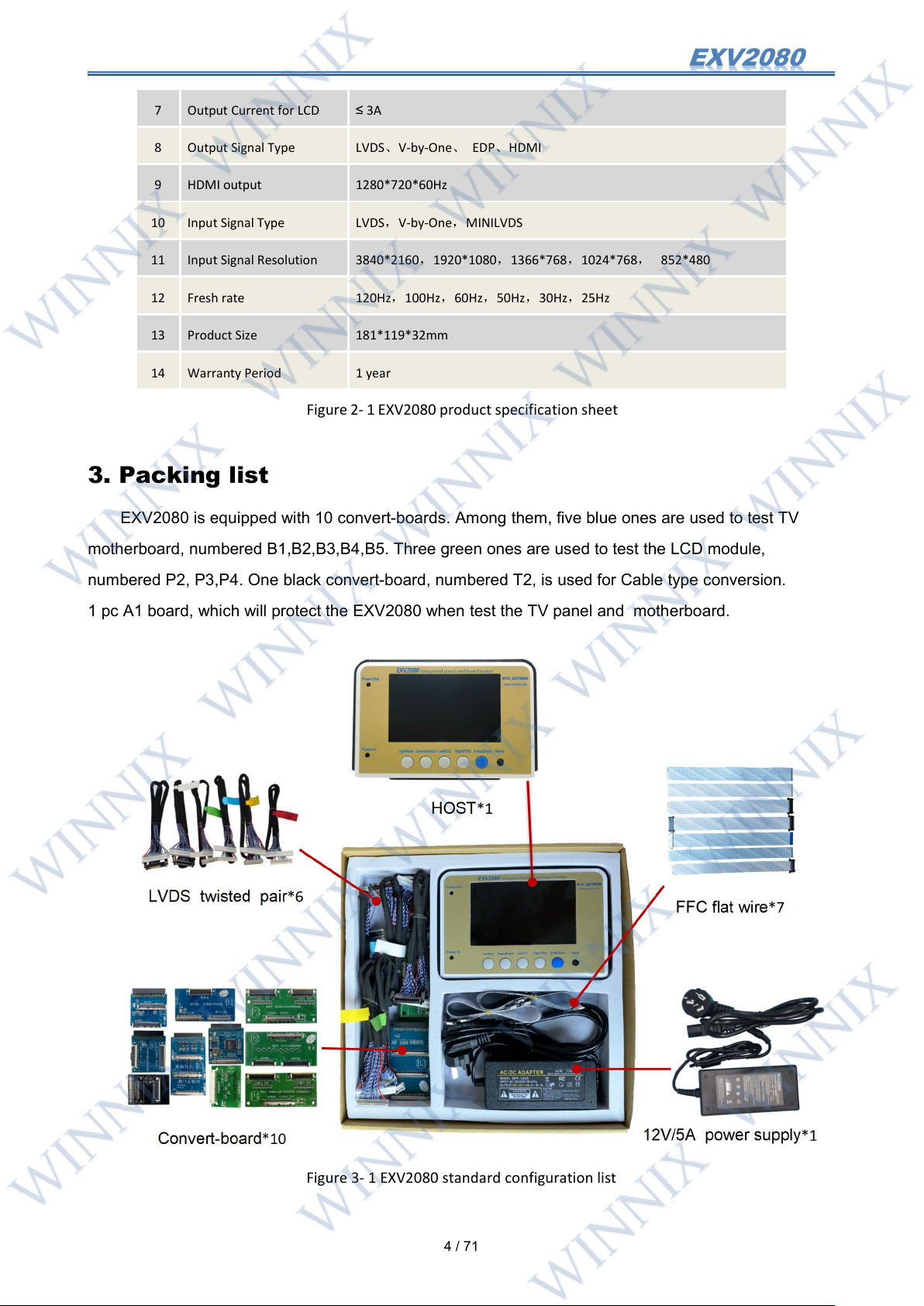
EXV2080 is equipped with 10 convert-boards. Among them, five blue ones are used to test TV
motherboard, numbered B1,B2,B3,B4,B5. Three green ones are used to test the LCD module,
numbered P2, P3,P4. One black convert-board, numbered T2, is used for Cable type conversion.
1 pc A1 board, which will protect the EXV2080 when test the TV panel and motherboard.
Figure 3- 1 EXV2080 standard configuration list
Page 6
5
/ 71
4. Structure and function
①②③
④
⑤
⑥
⑦
⑧⑨⑩⑪⑫⑬⑭
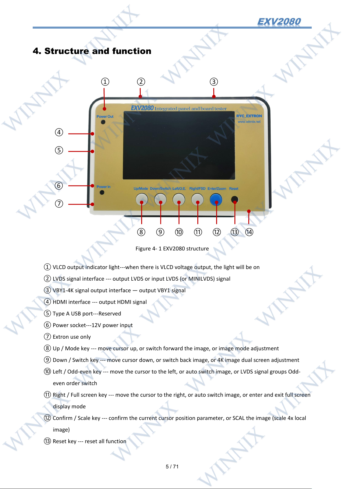
Figure 4- 1 EXV2080 structure
① VLCD output indicator light---when there is VLCD voltage output, the light will be on
② LVDS signal interface --- output LVDS or input LVDS (or MINILVDS) signal
③ VBY1-4K signal output interface — output VBY1 signal
④ HDMI interface --- output HDMI signal
⑤ Type A USB port---Reserved
⑥ Power socket---12V power input
⑦ Extron use only
⑧ Up / Mode key --- move cursor up, or switch forward the image, or image mode adjustment
⑨ Down / Switch key --- move cursor down, or switch back image, or 4K image dual screen adjustment
⑩ Left / Odd-even key --- move the cursor to the left, or auto switch image, or LVDS signal groups Odd-
even order switch
⑪ Right / Full screen key --- move the cursor to the right, or auto switch image, or enter and exit full screen
display mode
⑫ Confirm / Scale key --- confirm the current cursor position parameter, or SCAL the image (scale 4x local
image)
⑬ Reset key --- reset all function
Page 7
6
/ 71
⑭ MicroUSB port --- online firmware upgrade socket
5. Main interface description
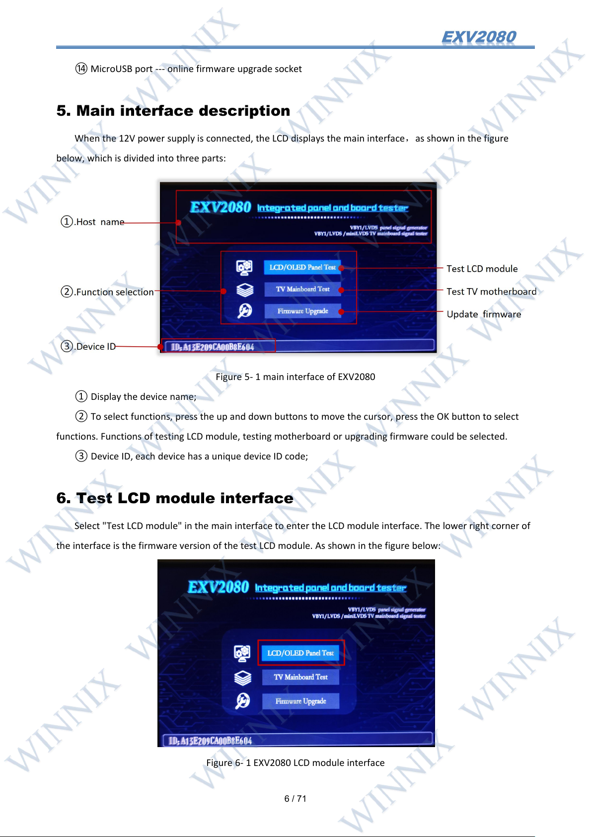
When the 12V power supply is connected, the LCD displays the main interface,as shown in the figure
below, which is divided into three parts:
Figure 5- 1 main interface of EXV2080
① Display the device name;
② To select functions, press the up and down buttons to move the cursor, press the OK button to select
functions. Functions of testing LCD module, testing motherboard or upgrading firmware could be selected.
③ Device ID, each device has a unique device ID code;
6. Test LCD module interface
Select "Test LCD module" in the main interface to enter the LCD module interface. The lower right corner of
the interface is the firmware version of the test LCD module. As shown in the figure below:
Figure 6- 1 EXV2080 LCD module interface
Page 8
7
/ 71
6.1 LCD module parameter selection
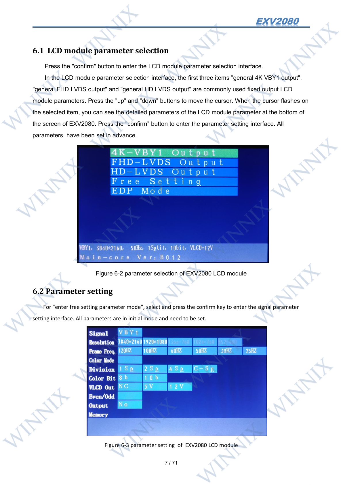
Press the "confirm" button to enter the LCD module parameter selection interface.
In the LCD module parameter selection interface, the first three items "general 4K VBY1 output",
"general FHD LVDS output" and "general HD LVDS output" are commonly used fixed output LCD
module parameters. Press the "up" and "down" buttons to move the cursor. When the cursor flashes on
the selected item, you can see the detailed parameters of the LCD module parameter at the bottom of
the screen of EXV2080. Press the "confirm" button to enter the parameter setting interface. All
parameters have been set in advance.
Figure 6-2 parameter selection of EXV2080 LCD module
6.2 Parameter setting
For "enter free setting parameter mode", select and press the confirm key to enter the signal parameter
setting interface. All parameters are in initial mode and need to be set.
Figure 6-3 parameter setting of EXV2080 LCD module
Page 9
8
/ 71
Select the corresponding mode in the LCD module parameter selection interface, press the confirm button
Cable
Cable
EXV2080
Convert
Board
LCD module
to enter the parameter setting interface, and press the "reset" button to return to the LCD module
parameter selection interface;
With the "up", "down", "left", "right" and "confirm" buttons, select the corresponding parameters of the
LCD module to be tested. If the first three general parameters are selected in the LCD module parameter
selection interface, you can see that all the parameters have been set after entering the parameter setting
interface. At this time, you can also move the cursor and press the OK key to modify the parameters;
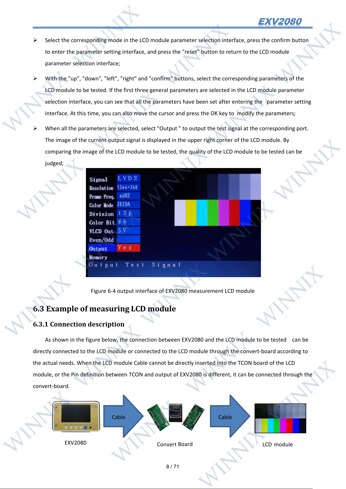
When all the parameters are selected, select "Output " to output the test signal at the corresponding port.
The image of the current output signal is displayed in the upper right corner of the LCD module. By
comparing the image of the LCD module to be tested, the quality of the LCD module to be tested can be
judged;
Figure 6-4 output interface of EXV2080 measurement LCD module
6.3 Example of measuring LCD module
6.3.1 Connection description
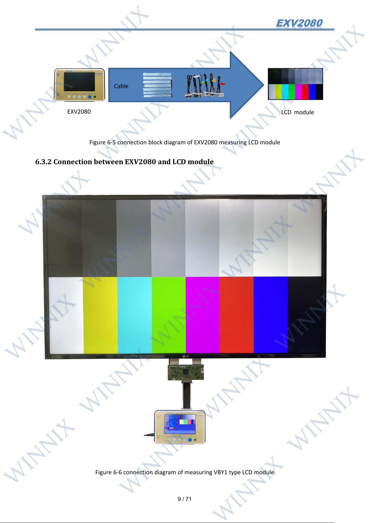
As shown in the figure below, the connection between EXV2080 and the LCD module to be tested can be
directly connected to the LCD module or connected to the LCD module through the convert-board according to
the actual needs. When the LCD module Cable cannot be directly inserted into the TCON board of the LCD
module, or the Pin definition between TCON and output of EXV2080 is different, it can be connected through the
convert-board.
Page 10
9
/ 71
Figure 6-5 connection block diagram of EXV2080 measuring LCD module
Cable
EXV2080
LCD module
6.3.2 Connection between EXV2080 and LCD module
Figure 6-6 connection diagram of measuring VBY1 type LCD module
Page 11
10
/ 71
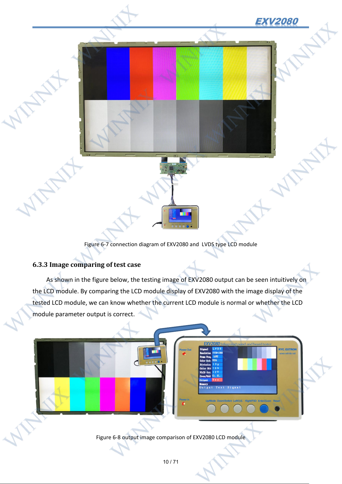
Figure 6-7 connection diagram of EXV2080 and LVDS type LCD module
6.3.3 Image comparing of test case
As shown in the figure below, the testing image of EXV2080 output can be seen intuitively on
the LCD module. By comparing the LCD module display of EXV2080 with the image display of the
tested LCD module, we can know whether the current LCD module is normal or whether the LCD
module parameter output is correct.
Figure 6-8 output image comparison of EXV2080 LCD module
Page 12
11
/ 71
7. The UI of testing TV motherboard
Enter the UI of testing TV motherboard from the initial interface.
7.1 Enter the UI of testing TV motherboard
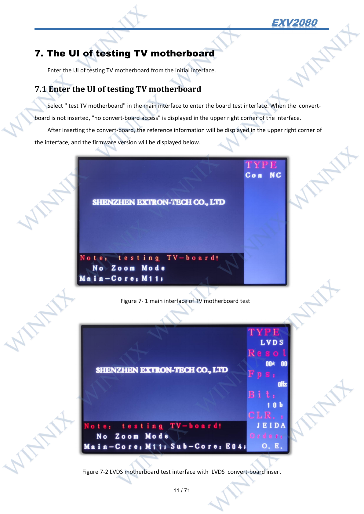
Select " test TV motherboard" in the main interface to enter the board test interface. When the convert-
board is not inserted, "no convert-board access" is displayed in the upper right corner of the interface.
After inserting the convert-board, the reference information will be displayed in the upper right corner of
the interface, and the firmware version will be displayed below.
Figure 7- 1 main interface of TV motherboard test
Figure 7-2 LVDS motherboard test interface with LVDS convert-board insert
Page 13
12
/ 71
7.2 Connecting TV motherboard to EXV2080
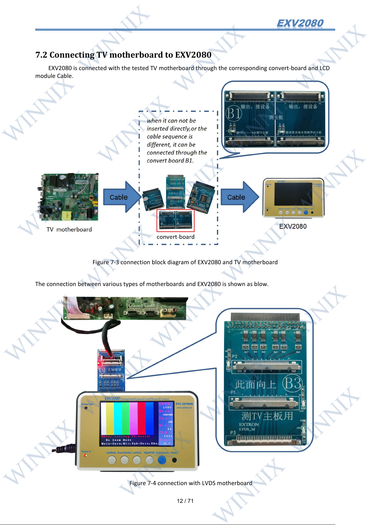
EXV2080 is connected with the tested TV motherboard through the corresponding convert-board and LCD
module Cable.
Figure 7-3 connection block diagram of EXV2080 and TV motherboard
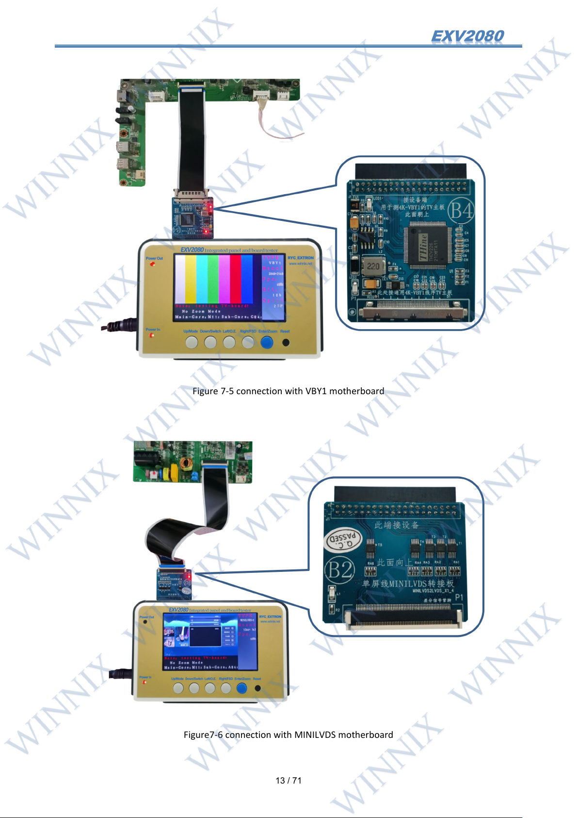
The connection between various types of motherboards and EXV2080 is shown as blow.
Figure 7-4 connection with LVDS motherboard
Page 14
13
/ 71
Figure 7-5 connection with VBY1 motherboard
Figure7-6 connection with MINILVDS motherboard
Page 15
14
/ 71
7.3 Brief introduction to the function of testing TV motherboard
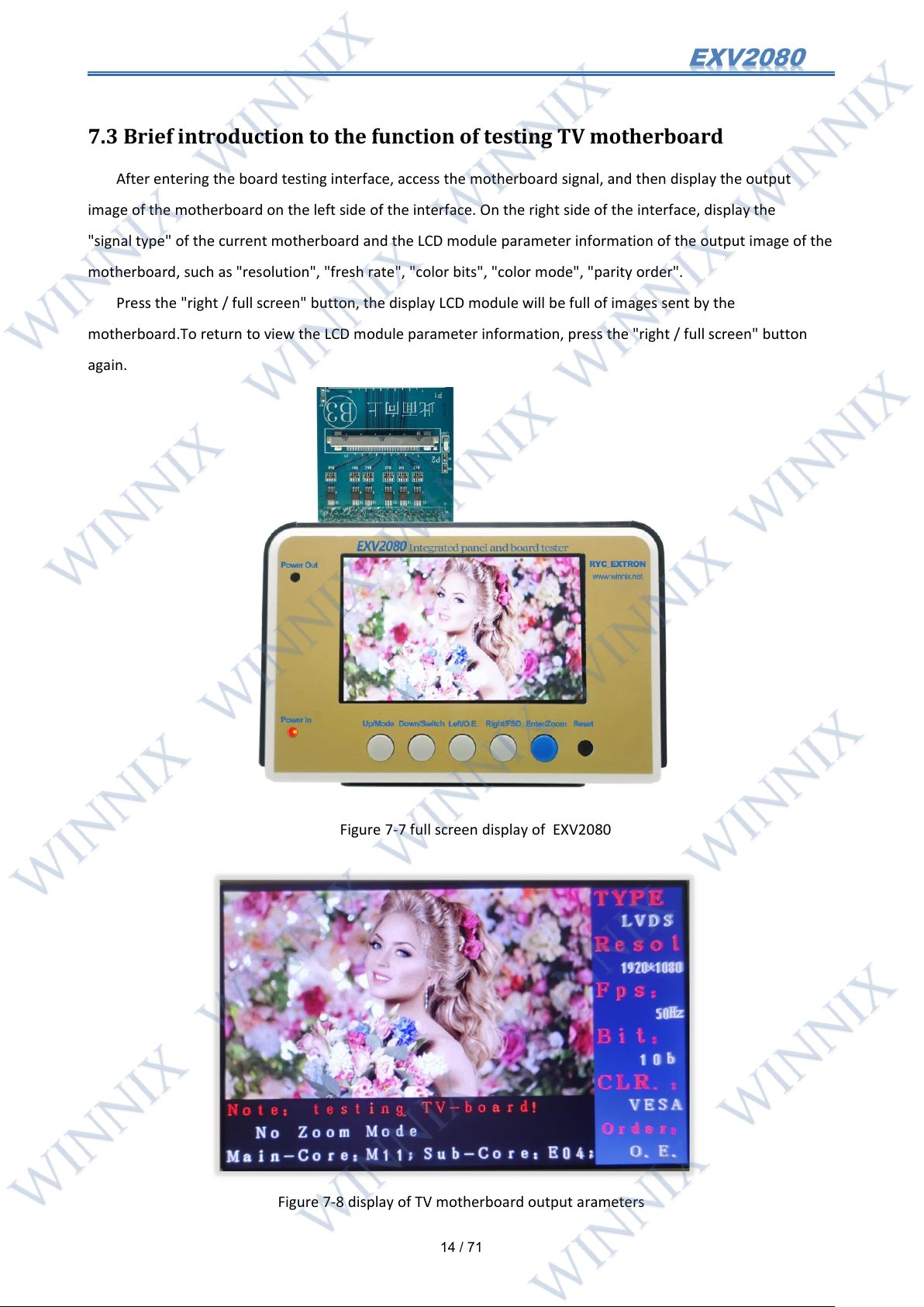
After entering the board testing interface, access the motherboard signal, and then display the output
image of the motherboard on the left side of the interface. On the right side of the interface, display the
"signal type" of the current motherboard and the LCD module parameter information of the output image of the
motherboard, such as "resolution", "fresh rate", "color bits", "color mode", "parity order".
Press the "right / full screen" button, the display LCD module will be full of images sent by the
motherboard.To return to view the LCD module parameter information, press the "right / full screen" button
again.
Figure 7-7 full screen display of EXV2080
Figure 7-8 display of TV motherboard output arameters
Page 16
15
/ 71
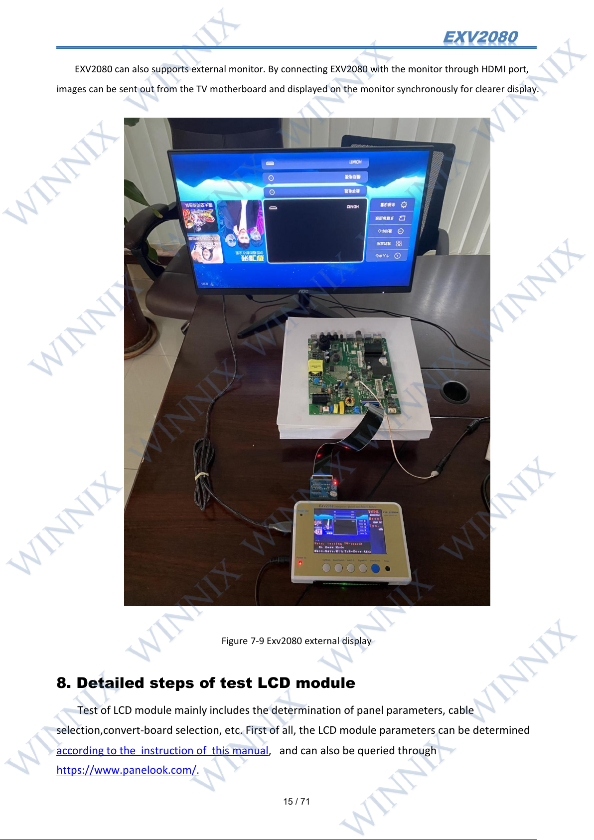
EXV2080 can also supports external monitor. By connecting EXV2080 with the monitor through HDMI port,
images can be sent out from the TV motherboard and displayed on the monitor synchronously for clearer display.
Figure 7-9 Exv2080 external display
8. Detailed steps of test LCD module
Test of LCD module mainly includes the determination of panel parameters, cable
selection,convert-board selection, etc. First of all, the LCD module parameters can be determined
according to the instruction of this manual, and can also be queried through
https://www.panelook.com/.
Page 17
16
/ 71
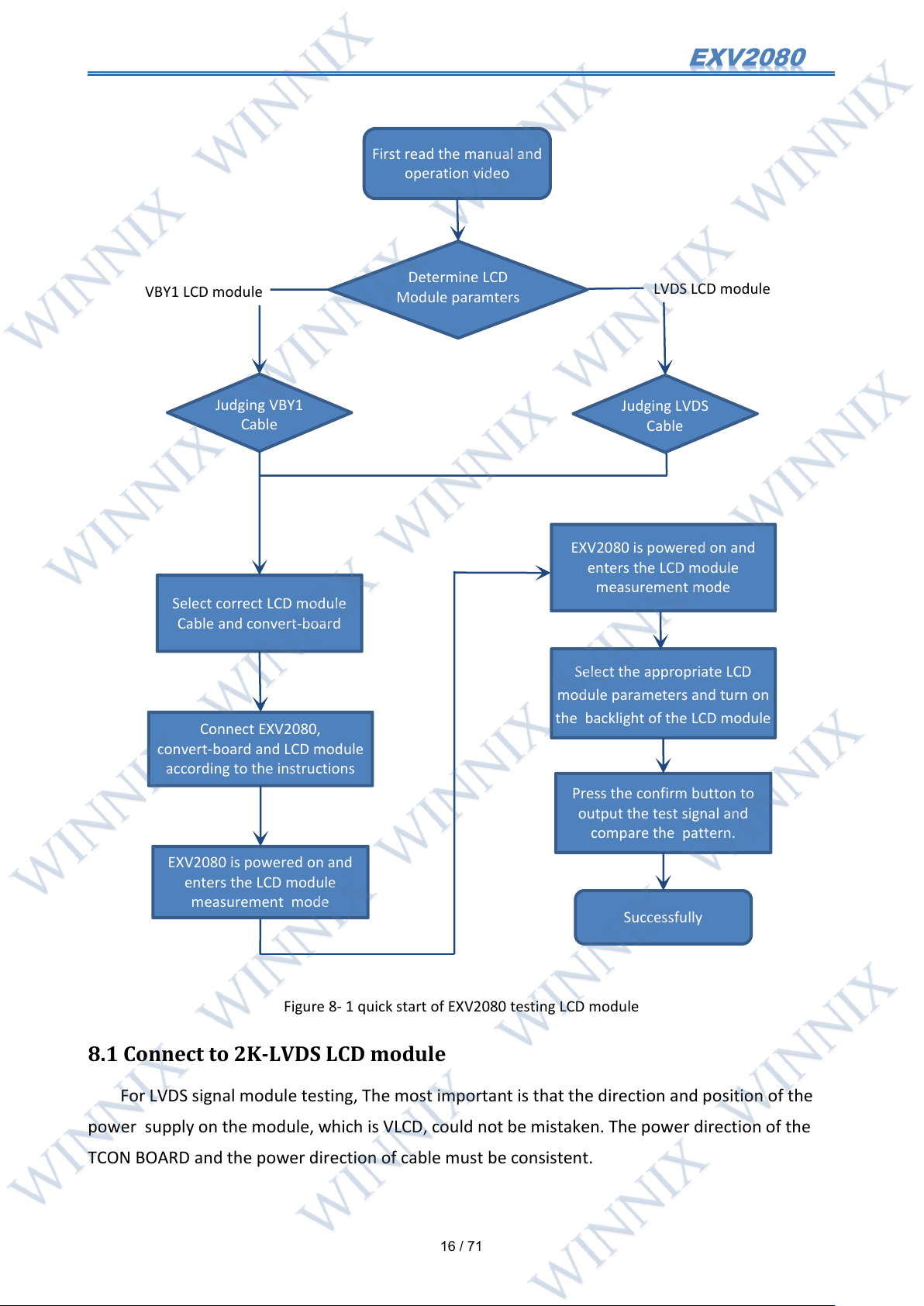
8.1 Connect to 2K-LVDS LCD module
First read the manual and
operation video
Determine LCD
Module paramters
Judging VBY1
Cable
Select correct LCD module
Cable and convert-board
Connect EXV2080,
convert-board and LCD module
according to the instructions
EXV2080 is powered on and
enters the LCD module
measurement mode
Select the appropriate LCD
module parameters and turn on
the backlight of the LCD module
Press the confirm button to
output the test signal and
compare the pattern.
Successfully
VBY1 LCD module
LVDS LCD module
Judging LVDS
Cable
EXV2080 is powered on and
enters the LCD module
measurement mode
For LVDS signal module testing, The most important is that the direction and position of the
power supply on the module, which is VLCD, could not be mistaken. The power direction of the
TCON BOARD and the power direction of cable must be consistent.
Figure 8- 1 quick start of EXV2080 testing LCD module
Page 18
17
/ 71
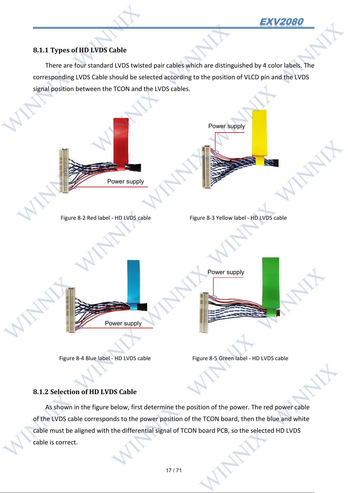
8.1.1 Types of HD LVDS Cable
Power supply
Power supply
Power supply
Power supply
There are four standard LVDS twisted pair cables which are distinguished by 4 color labels. The
corresponding LVDS Cable should be selected according to the position of VLCD pin and the LVDS
signal position between the TCON and the LVDS cables.
Figure 8-2 Red label - HD LVDS cable Figure 8-3 Yellow label - HD LVDS cable
Figure 8-4 Blue label - HD LVDS cable Figure 8-5 Green label - HD LVDS cable
8.1.2 Selection of HD LVDS Cable
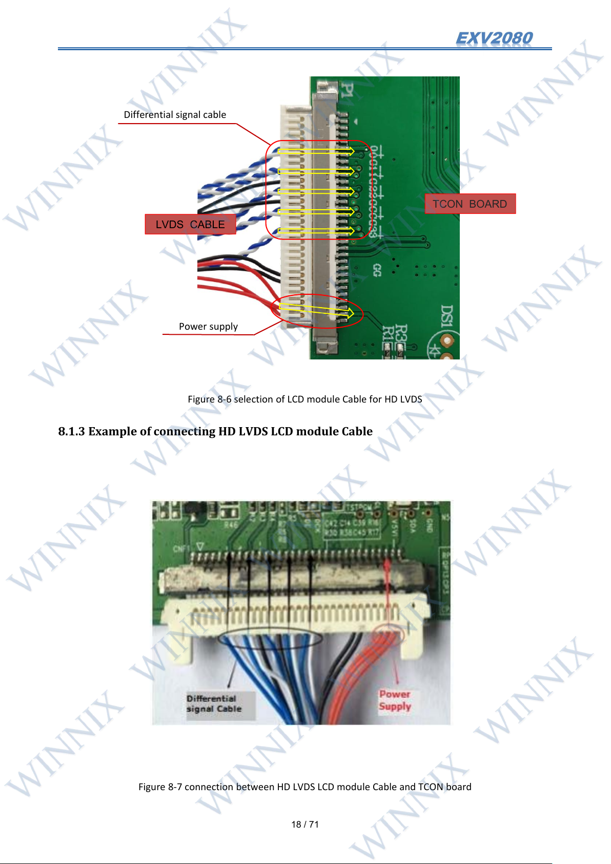
As shown in the figure below, first determine the position of the power. The red power cable
of the LVDS cable corresponds to the power position of the TCON board, then the blue and white
cable must be aligned with the differential signal of TCON board PCB, so the selected HD LVDS
cable is correct.
Page 19
18
/ 71
Figure 8-6 selection of LCD module Cable for HD LVDS
TCON BOARD
LVDS CABLE
Differential signal cable
Power supply
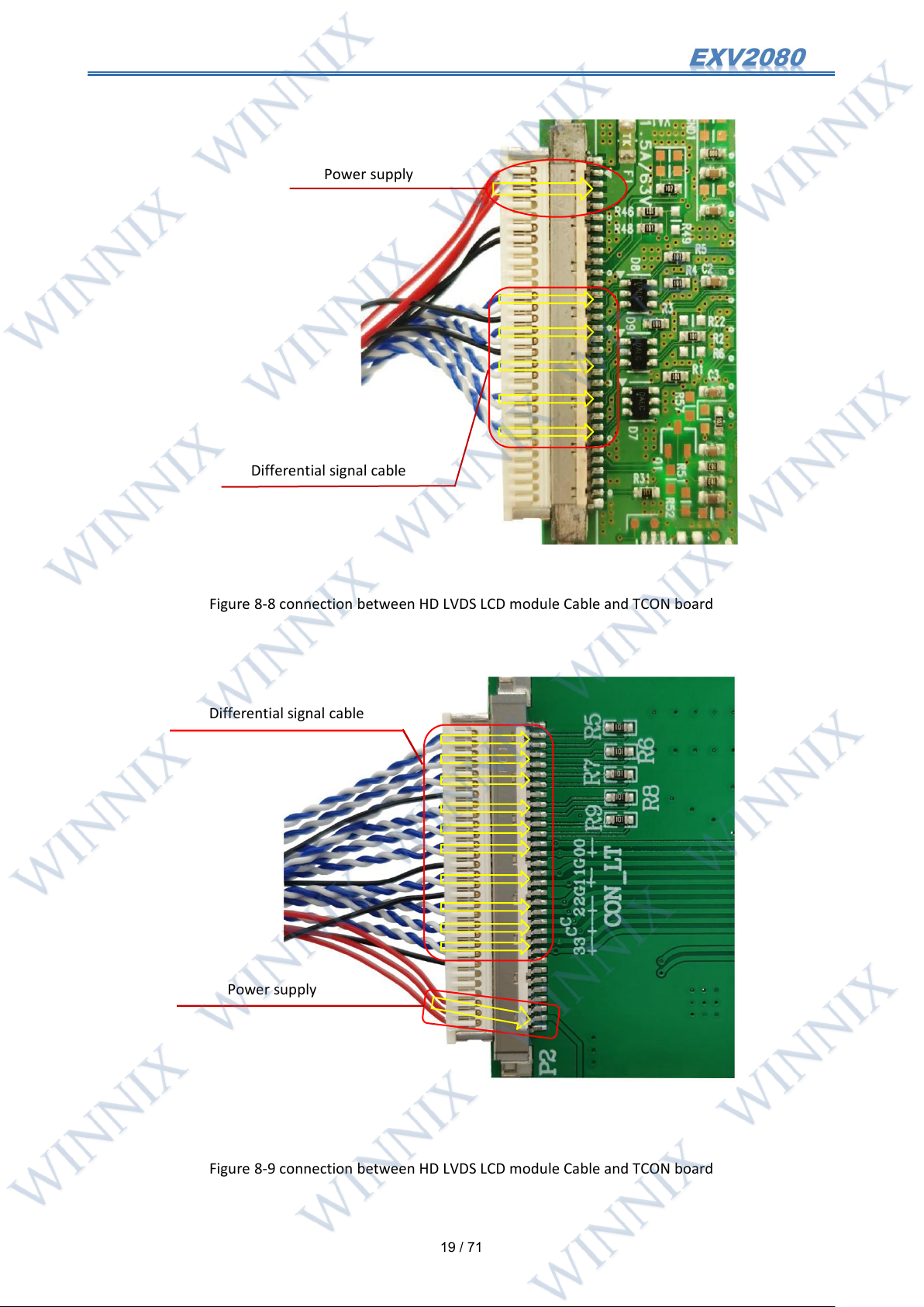
8.1.3 Example of connecting HD LVDS LCD module Cable
Figure 8-7 connection between HD LVDS LCD module Cable and TCON board
Page 20
19
/ 71
Figure 8-8 connection between HD LVDS LCD module Cable and TCON board
Power supply
Differential signal cable
Differential signal cable
Power supply
Figure 8-9 connection between HD LVDS LCD module Cable and TCON board
Page 21
20
/ 71
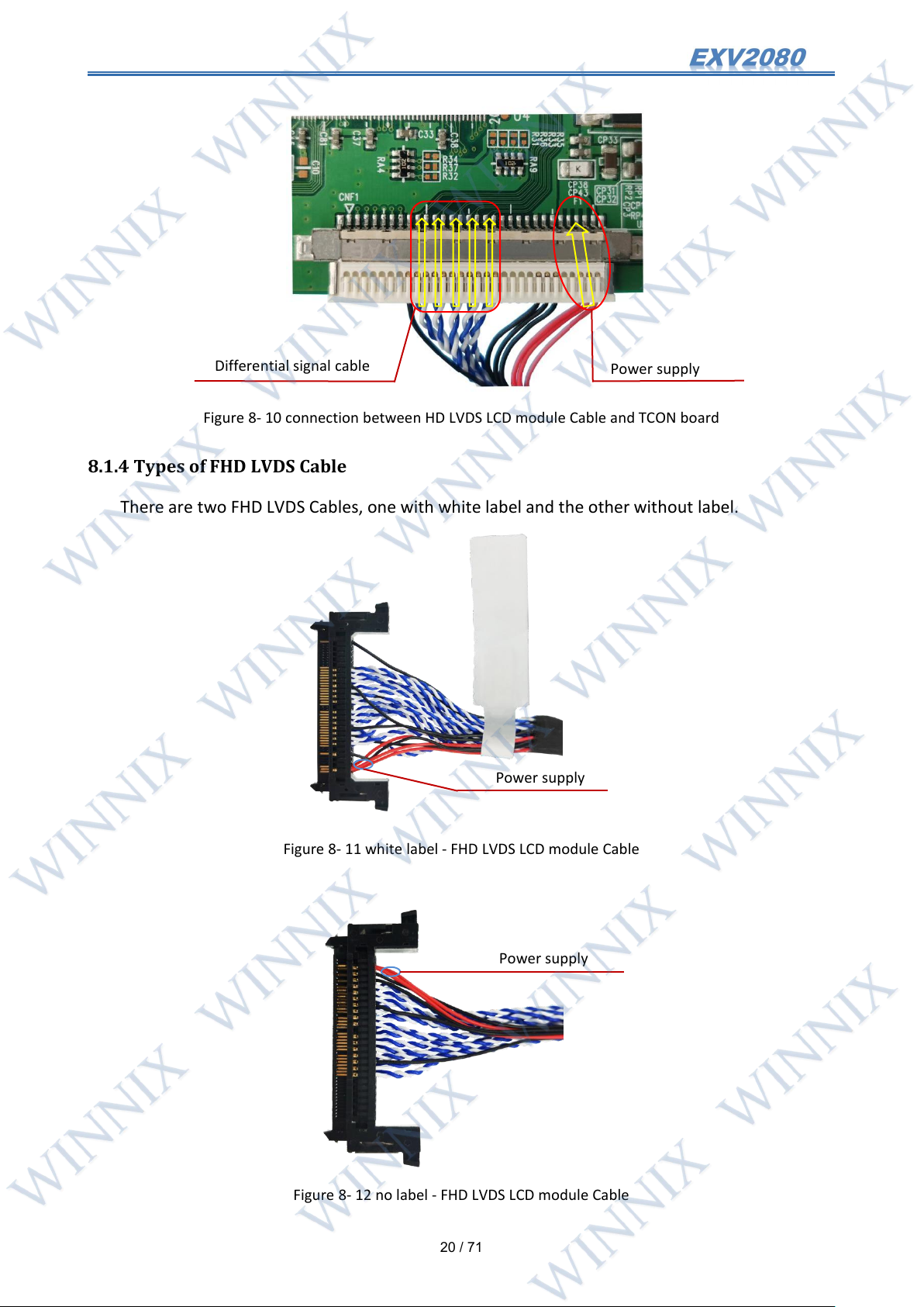
Figure 8- 10 connection between HD LVDS LCD module Cable and TCON board
Power supply
Power supply
Differential signal cable
Power supply
8.1.4 Types of FHD LVDS Cable
There are two FHD LVDS Cables, one with white label and the other without label.
Figure 8- 11 white label - FHD LVDS LCD module Cable
Figure 8- 12 no label - FHD LVDS LCD module Cable
Page 22
21
/ 71
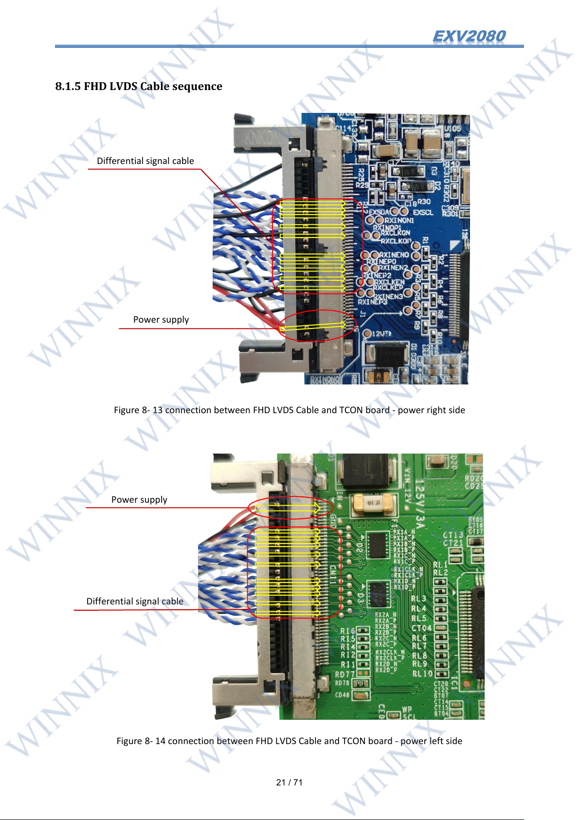
8.1.5 FHD LVDS Cable sequence
Power supply
Differential signal cable
Power supply
Differential signal cable
Figure 8- 13 connection between FHD LVDS Cable and TCON board - power right side
Figure 8- 14 connection between FHD LVDS Cable and TCON board - power left side
Page 23
22
/ 71
8.1.6 Connect to FHD LVDS dual LCD Cable
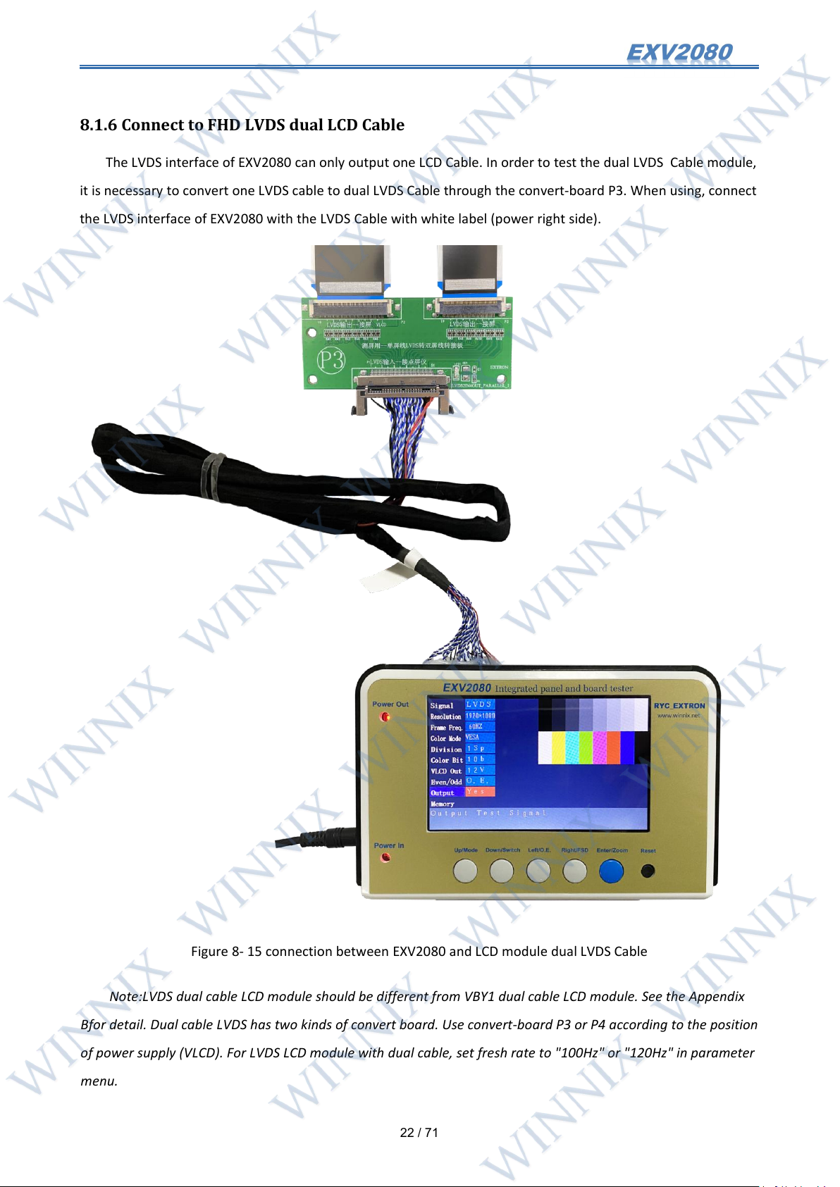
The LVDS interface of EXV2080 can only output one LCD Cable. In order to test the dual LVDS Cable module,
it is necessary to convert one LVDS cable to dual LVDS Cable through the convert-board P3. When using, connect
the LVDS interface of EXV2080 with the LVDS Cable with white label (power right side).
Figure 8- 15 connection between EXV2080 and LCD module dual LVDS Cable
Note:LVDS dual cable LCD module should be different from VBY1 dual cable LCD module. See the Appendix
Bfor detail. Dual cable LVDS has two kinds of convert board. Use convert-board P3 or P4 according to the position
of power supply (VLCD). For LVDS LCD module with dual cable, set fresh rate to "100Hz" or "120Hz" in parameter
menu.
Page 24
23
/ 71
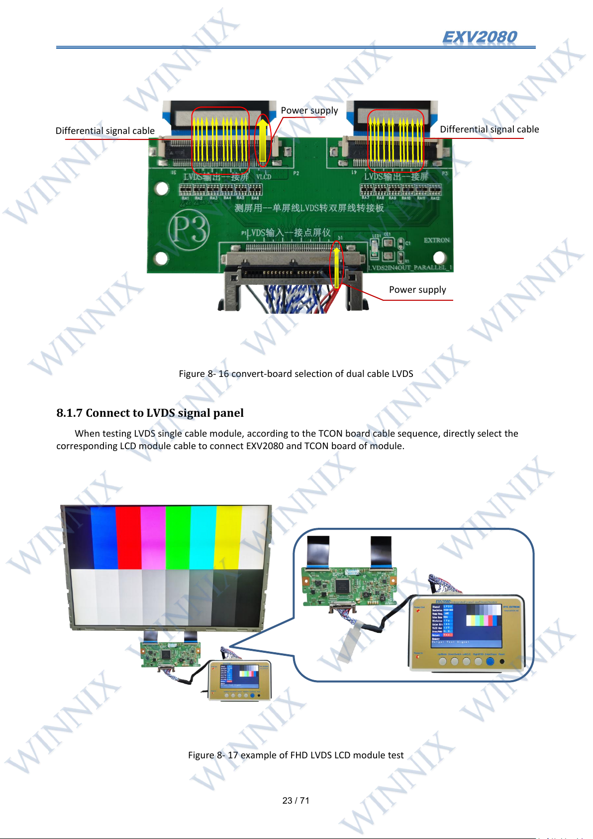
Figure 8- 16 convert-board selection of dual cable LVDS
Power supply
Differential signal cable
Differential signal cable
Power supply
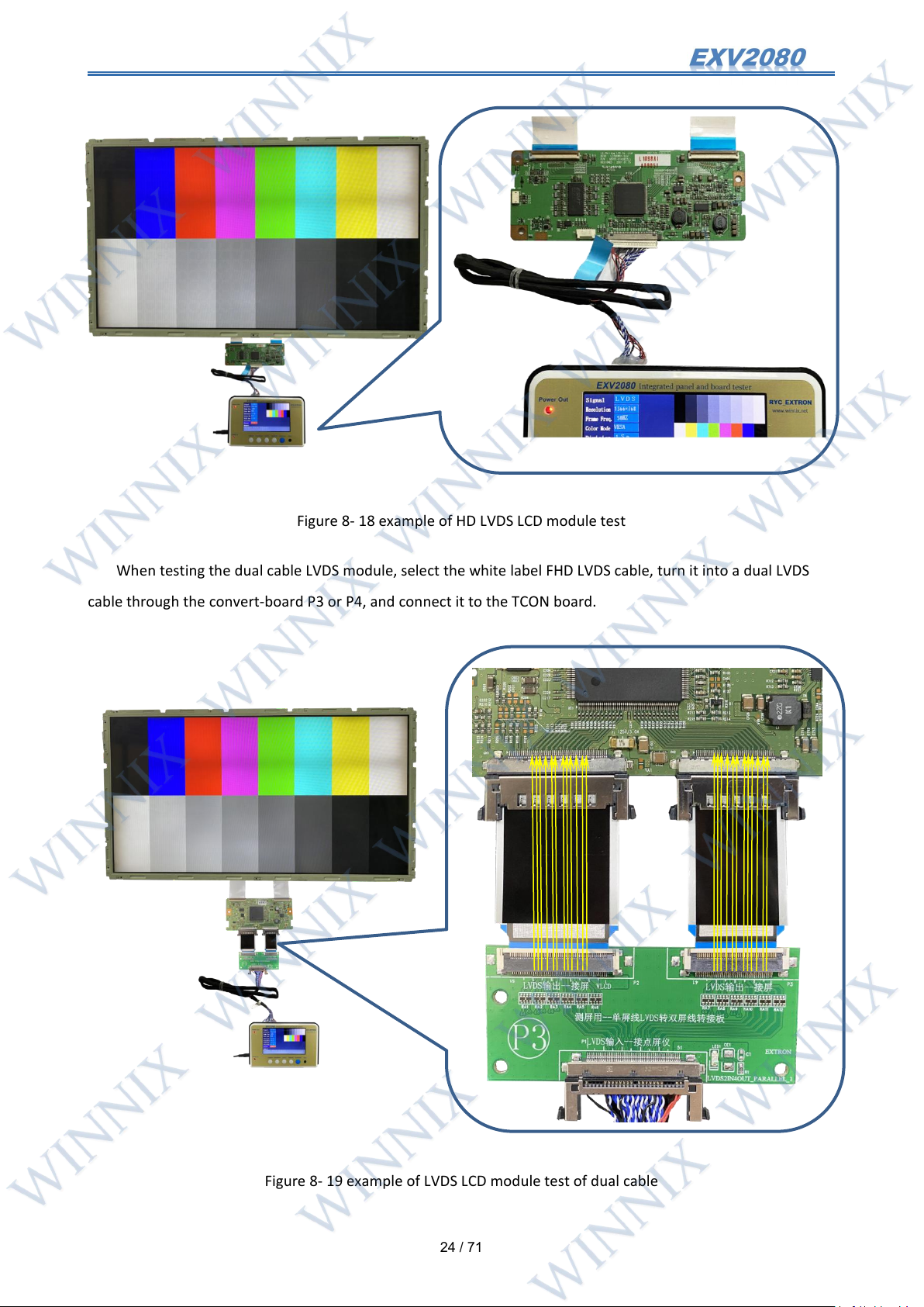
8.1.7 Connect to LVDS signal panel
When testing LVDS single cable module, according to the TCON board cable sequence, directly select the
corresponding LCD module cable to connect EXV2080 and TCON board of module.
Figure 8- 17 example of FHD LVDS LCD module test
Page 25
24
/ 71
Figure 8- 18 example of HD LVDS LCD module test
When testing the dual cable LVDS module, select the white label FHD LVDS cable, turn it into a dual LVDS
cable through the convert-board P3 or P4, and connect it to the TCON board.
Figure 8- 19 example of LVDS LCD module test of dual cable
Page 26
25
/ 71
8.2 Connect to 4K-VBY1 LCD module
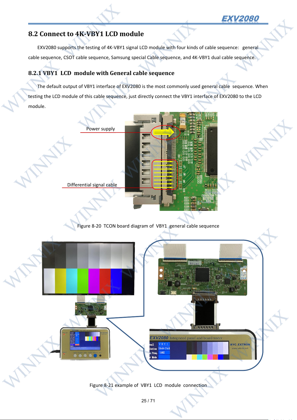
Differential signal cable
Power supply
EXV2080 supports the testing of 4K-VBY1 signal LCD module with four kinds of cable sequence: general
cable sequence, CSOT cable sequence, Samsung special Cable sequence, and 4K-VBY1 dual cable sequence.
8.2.1 VBY1 LCD module with General cable sequence
The default output of VBY1 interface of EXV2080 is the most commonly used general cable sequence. When
testing the LCD module of this cable sequence, just directly connect the VBY1 interface of EXV2080 to the LCD
module.
Figure 8-20 TCON board diagram of VBY1 general cable sequence
Figure 8-21 example of VBY1 LCD module connection
Page 27
26
/ 71
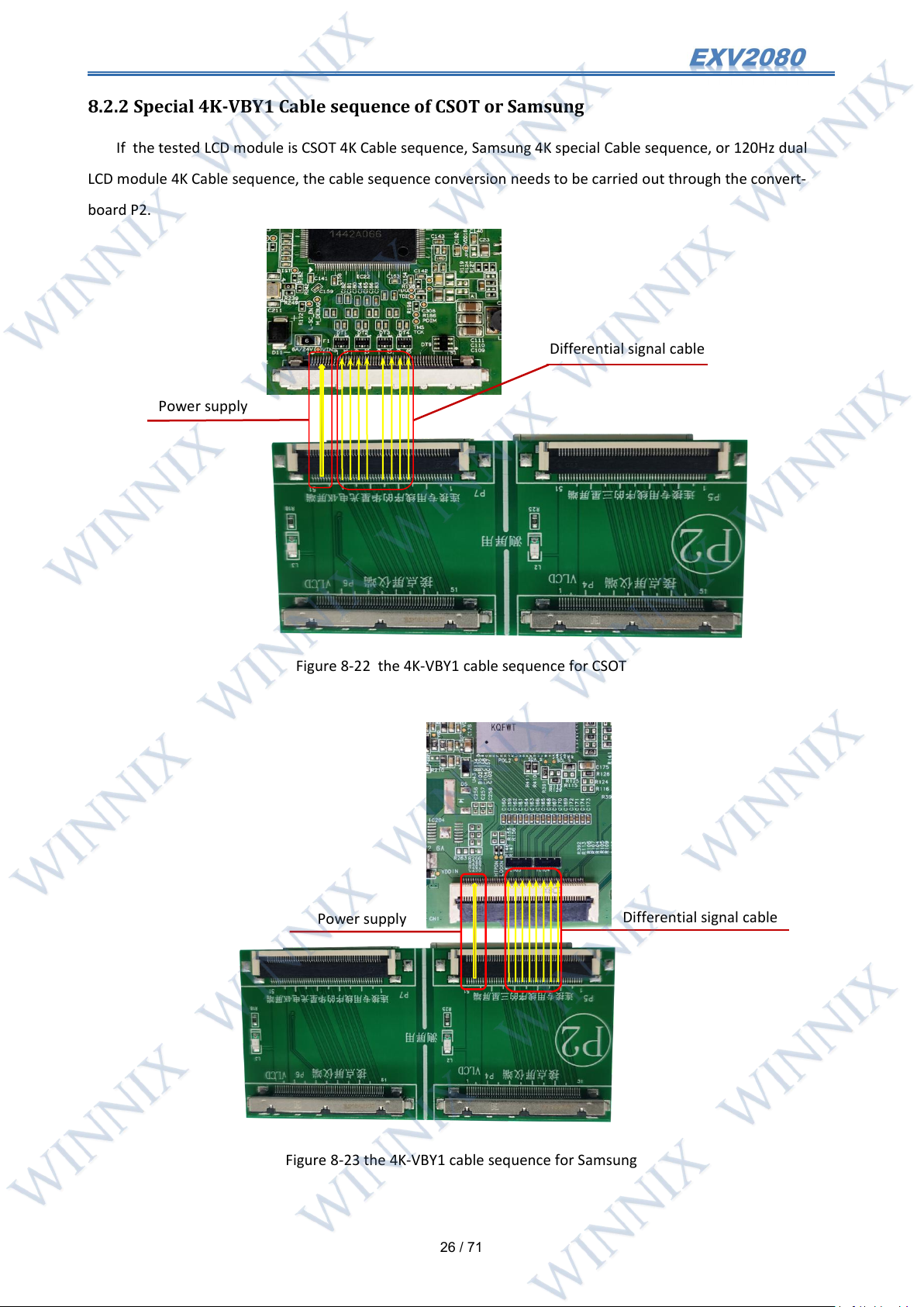
8.2.2 Special 4K-VBY1 Cable sequence of CSOT or Samsung
Differential signal cable
Power supply
Power supply
Differential signal cable
If the tested LCD module is CSOT 4K Cable sequence, Samsung 4K special Cable sequence, or 120Hz dual
LCD module 4K Cable sequence, the cable sequence conversion needs to be carried out through the convert-
board P2.
Figure 8-22 the 4K-VBY1 cable sequence for CSOT
Figure 8-23 the 4K-VBY1 cable sequence for Samsung
Page 28
27
/ 71
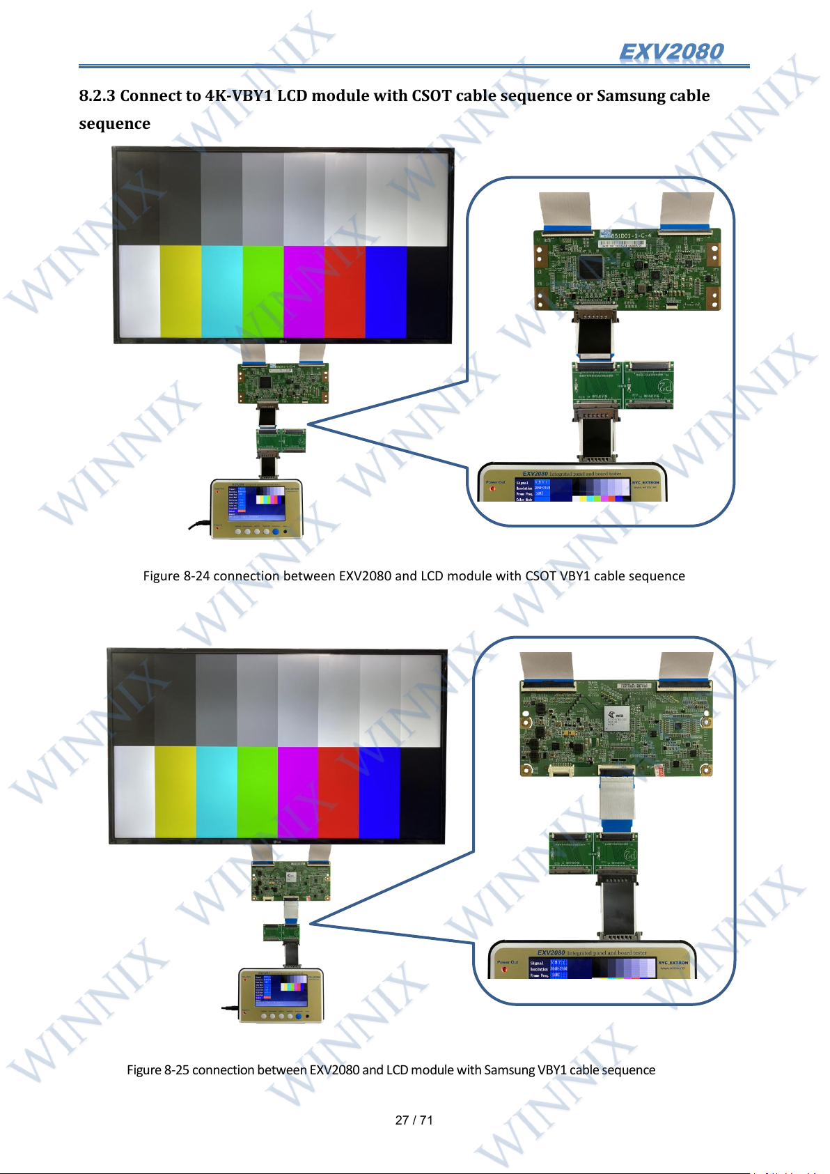
8.2.3 Connect to 4K-VBY1 LCD module with CSOT cable sequence or Samsung cable
sequence
Figure 8-24 connection between EXV2080 and LCD module with CSOT VBY1 cable sequence
Figure8-25connectionbetweenEXV2080andLCD modulewith SamsungVBY1 cablesequence
Page 29
28
/ 71
8.2.4 Connect to 4K-VBY1 dual cable LCD module
Differential signal cable
Differential signal cable
Differential signal cable
Differential signal cable
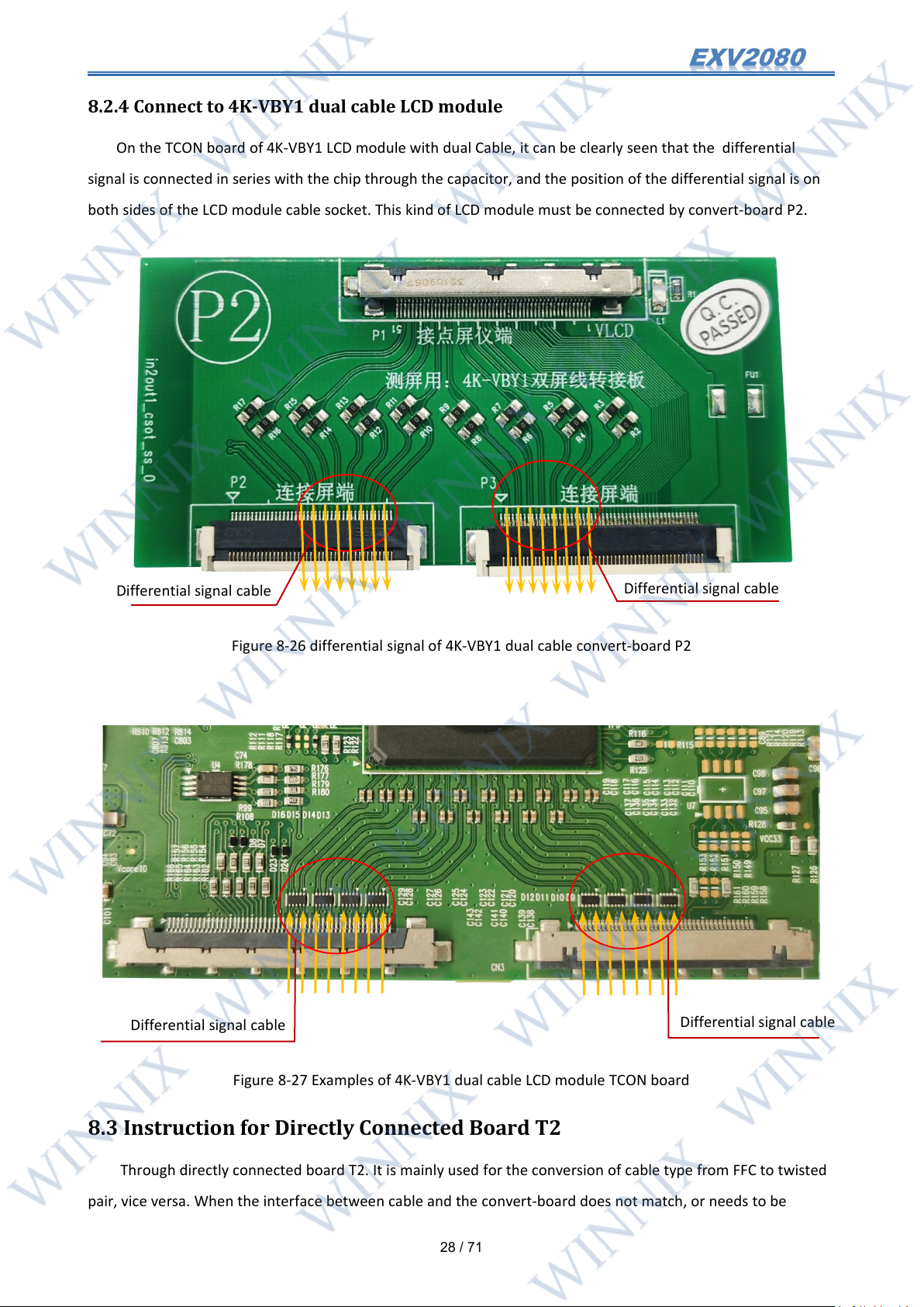
On the TCON board of 4K-VBY1 LCD module with dual Cable, it can be clearly seen that the differential
signal is connected in series with the chip through the capacitor, and the position of the differential signal is on
both sides of the LCD module cable socket. This kind of LCD module must be connected by convert-board P2.
Figure 8-26 differential signal of 4K-VBY1 dual cable convert-board P2
Figure 8-27 Examples of 4K-VBY1 dual cable LCD module TCON board
8.3 Instruction for Directly Connected Board T2
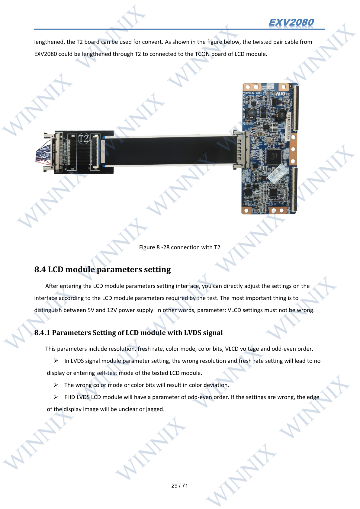
Through directly connected board T2. It is mainly used for the conversion of cable type from FFC to twisted
pair, vice versa. When the interface between cable and the convert-board does not match, or needs to be
Page 30
29
/ 71
lengthened, the T2 board can be used for convert. As shown in the figure below, the twisted pair cable from
EXV2080 could be lengthened through T2 to connected to the TCON board of LCD module.
Figure 8 -28 connection with T2
8.4 LCD module parameters setting
After entering the LCD module parameters setting interface, you can directly adjust the settings on the
interface according to the LCD module parameters required by the test. The most important thing is to
distinguish between 5V and 12V power supply. In other words, parameter: VLCD settings must not be wrong.
8.4.1 Parameters Setting of LCD module with LVDS signal
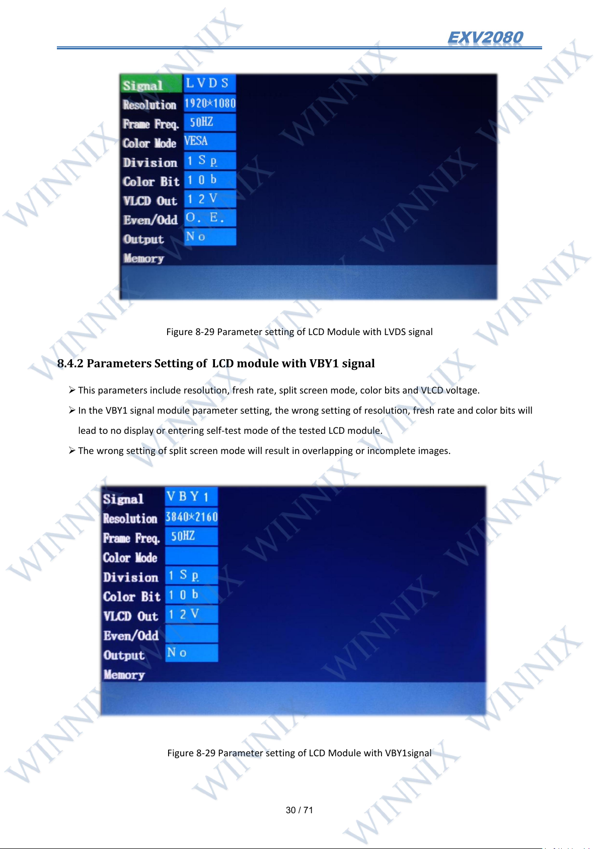
This parameters include resolution, fresh rate, color mode, color bits, VLCD voltage and odd-even order.
In LVDS signal module parameter setting, the wrong resolution and fresh rate setting will lead to no
display or entering self-test mode of the tested LCD module.
The wrong color mode or color bits will result in color deviation.
FHD LVDS LCD module will have a parameter of odd-even order. If the settings are wrong, the edge
of the display image will be unclear or jagged.
Page 31
30
/ 71
Figure 8-29 Parameter setting of LCD Module with LVDS signal
8.4.2 Parameters Setting of LCD module with VBY1 signal
This parameters include resolution, fresh rate, split screen mode, color bits and VLCD voltage.
In the VBY1 signal module parameter setting, the wrong setting of resolution, fresh rate and color bits will
lead to no display or entering self-test mode of the tested LCD module.
The wrong setting of split screen mode will result in overlapping or incomplete images.
Figure 8-29 Parameter setting of LCD Module with VBY1signal
Page 32
31
/ 71
8.5 Possible reasons why the tested Panel is not displayed
The output signal format does not match parameters of the tested LCD module. The solution is to
check the parameters from the datasheet of this module and then reset them.
If it is the LCD module with VBY1 signal, it may not correctly distinguish "General cable sequence",
"CSOT special cable sequence" and other cable sequences. According to the cable sequence of theLCD
module TCON board, it is necessary to determine whether the convert-board needs to be connected. If the
color bits is set incorrectly, there will be no display.
If it is the LVDS signal input LCD module, the LVDS cable may be selected incorrectly. According to
the cable sequence of the LCD module TCON board, select the correct LVDS cable.
If the cable is not connected correctly or damaged, check the connection or replace it.
It should be noted that EXV2080 has no LCD backlight drive,When testing LCD modules. it is
necessary to provide additional backlight power. Turn on the backlight first.
8.6 Test panel convert-boards of other special cable sequence
There are also some special convert-boards for test LCD module, which are rare. These convert-boards are
not included in the standard configuration packing list. Please refer to appendix:special Cable sequence convert-
board for its use and connection.
9. Motherboard test steps
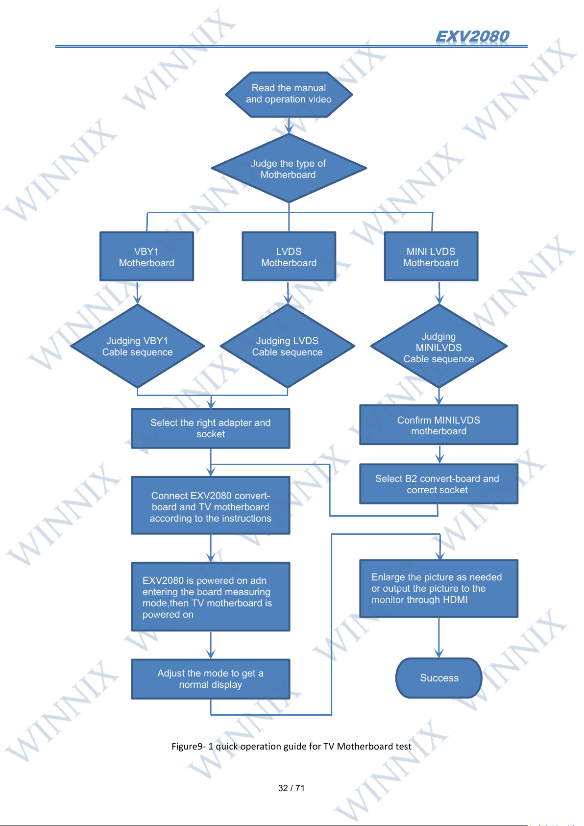
9.1 Quick operation guide
Read this manual and operation video.
Determine the signal type of TV motherboard to be tested.
Judge the cable sequence of TV motherboard.
Select the convert-board and socket according to the motherboard type and cable sequence.
Connect EXV2080, convert-board and motherboard being tested.
Power on the EXV2080. After entering the board testing mode, turn on the TV motherboard.
Adjust the mode through the mode button to get the normal display.
It can enlarge the display LCD module or output the LCD module to the external display through HDMI;
Page 33
32
/ 71
Enlarge the picture as needed
or output the picture to the
monitor through HDMI
Success
Judging VBY1
Cable sequence
Judging LVDS
Cable sequence
Judging
MINILVDS
Cable sequence
VBY1
Motherboard
MINI LVDS
Motherboard
LVDS
Motherboard
Read the manual
and operation video
Judge the type of
Motherboard
Select the right adapter and
socket
Confirm MINILVDS
motherboard
Select B2 convert-board and
correct socket
Adjust the mode to get a
normal display
EXV2080 is powered on adn
entering the board measuring
mode,then TV motherboard is
powered on
Connect EXV2080 convert-
board and TV motherboard
according to the instructions
Figure9- 1 quick operation guide for TV Motherboard test
Page 34
33
/ 71
9.2 Signal Type Judgment
1
2 pairs of differential Cables with resistance isolation
6 pairs of differential Cables with resistance isolation
9.2.1 LVDS Single LCD module Cable motherboard
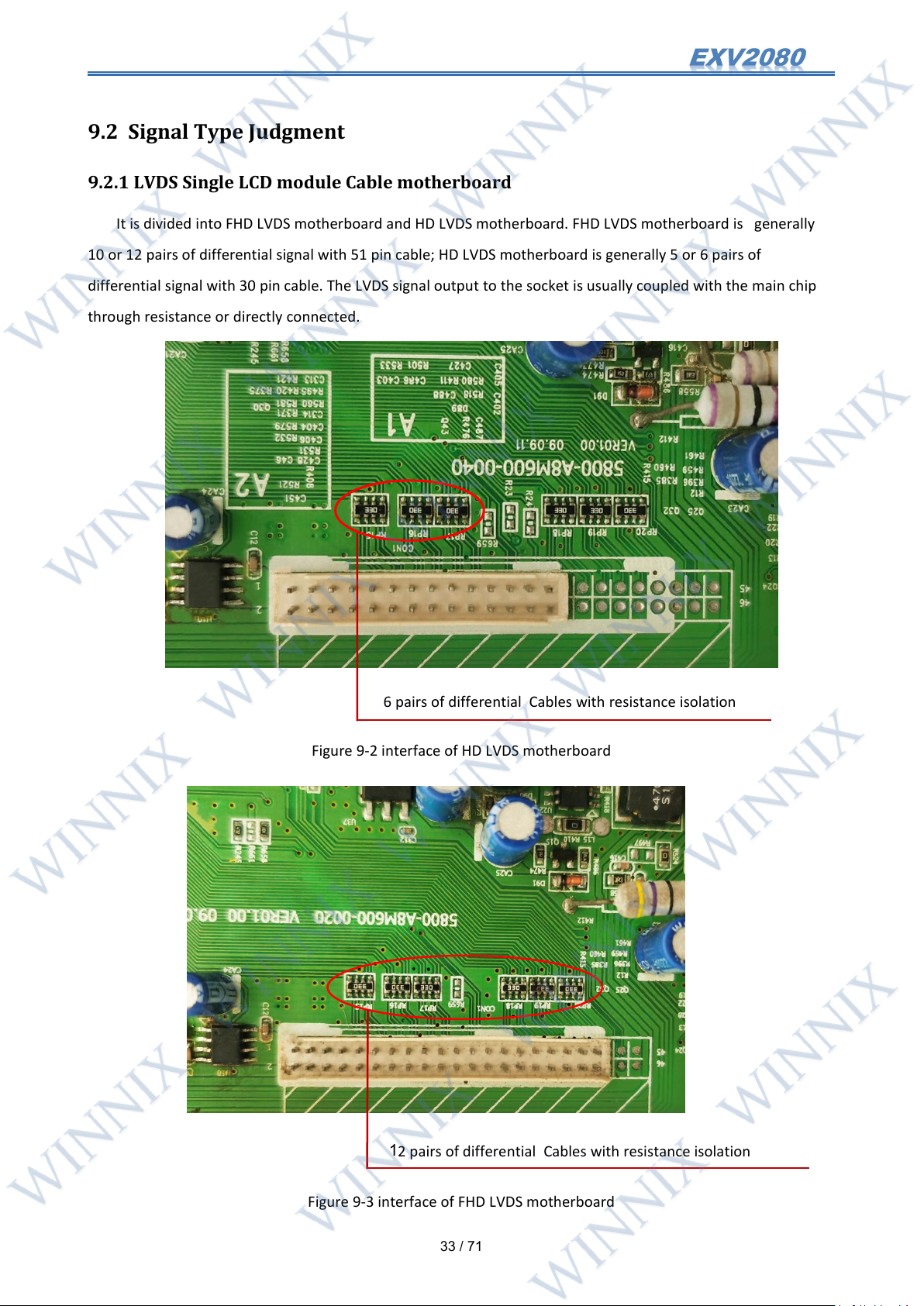
It is divided into FHD LVDS motherboard and HD LVDS motherboard. FHD LVDS motherboard is generally
10 or 12 pairs of differential signal with 51 pin cable; HD LVDS motherboard is generally 5 or 6 pairs of
differential signal with 30 pin cable. The LVDS signal output to the socket is usually coupled with the main chip
through resistance or directly connected.
Figure 9-2 interface of HD LVDS motherboard
Figure 9-3 interface of FHD LVDS motherboard
Page 35
34
/ 71
LVDS single Cable motherboard's Cable sequence judgment and convert-board 's connection, See《LVDS
Cable sequence and connection》
9.2.2 LVDS Dual LCD module Cable Motherboard
LVDS dual Cable motherboard, which has two cable sockets, a 51 pin, a 41 pin, both sides of the differential
signal are 12 pairs, or 10 pairs. Like the single cable LVDS motherboard, it is also coupled with the main chip
through resistance, or directly connected.
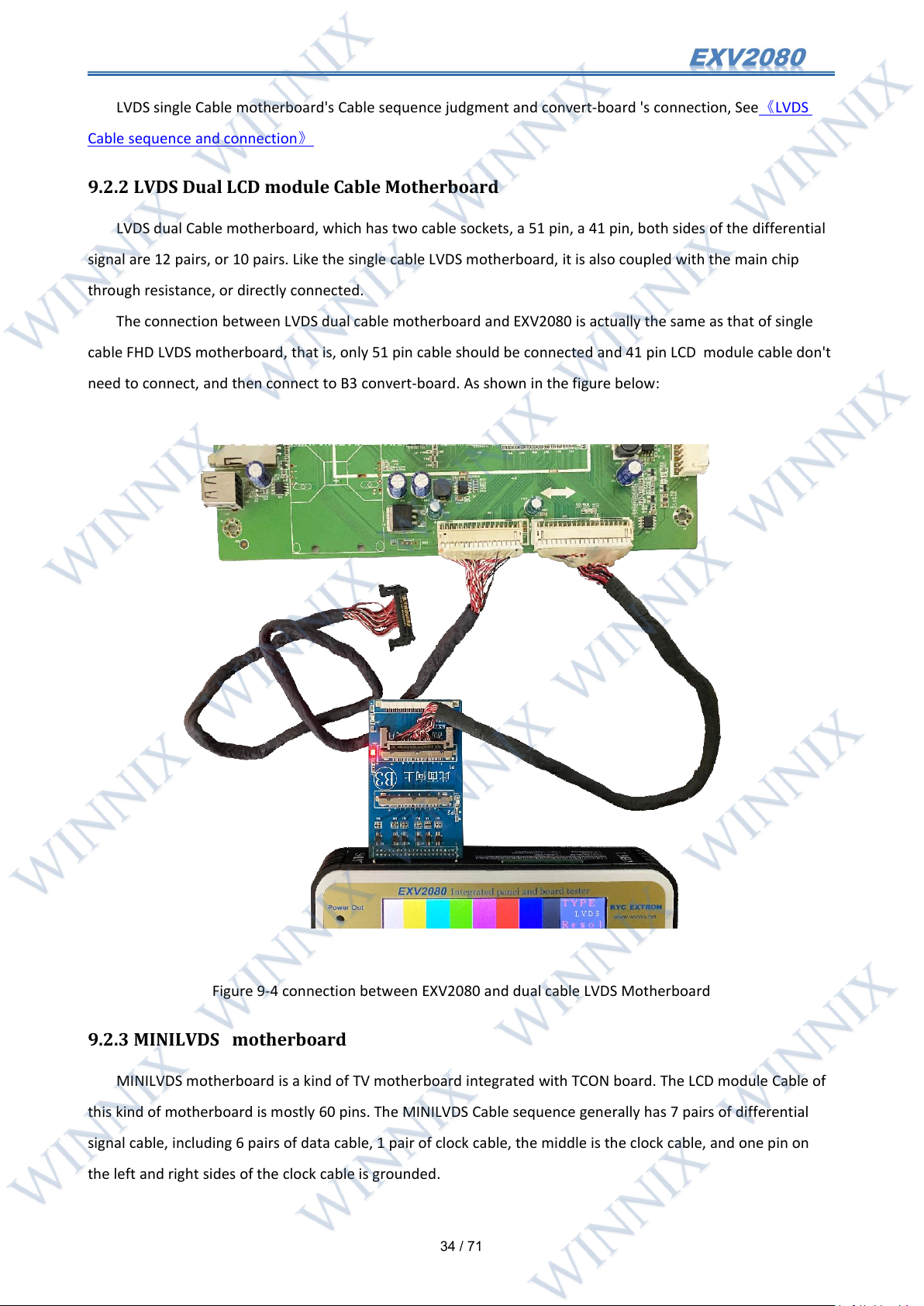
The connection between LVDS dual cable motherboard and EXV2080 is actually the same as that of single
cable FHD LVDS motherboard, that is, only 51 pin cable should be connected and 41 pin LCD module cable don't
need to connect, and then connect to B3 convert-board. As shown in the figure below:
Figure 9-4 connection between EXV2080 and dual cable LVDS Motherboard
9.2.3 MINILVDS motherboard
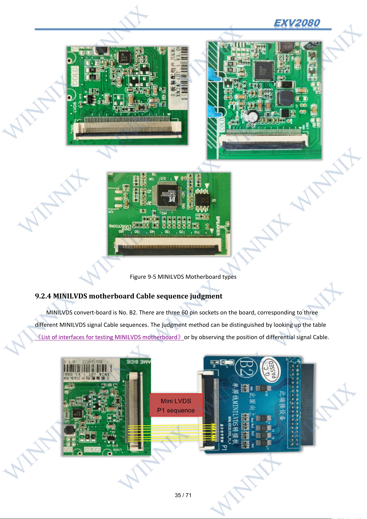
MINILVDS motherboard is a kind of TV motherboard integrated with TCON board. The LCD module Cable of
this kind of motherboard is mostly 60 pins. The MINILVDS Cable sequence generally has 7 pairs of differential
signal cable, including 6 pairs of data cable, 1 pair of clock cable, the middle is the clock cable, and one pin on
the left and right sides of the clock cable is grounded.
Page 36
35
/ 71
Figure 9-5 MINILVDS Motherboard types
9.2.4 MINILVDS motherboard Cable sequence judgment
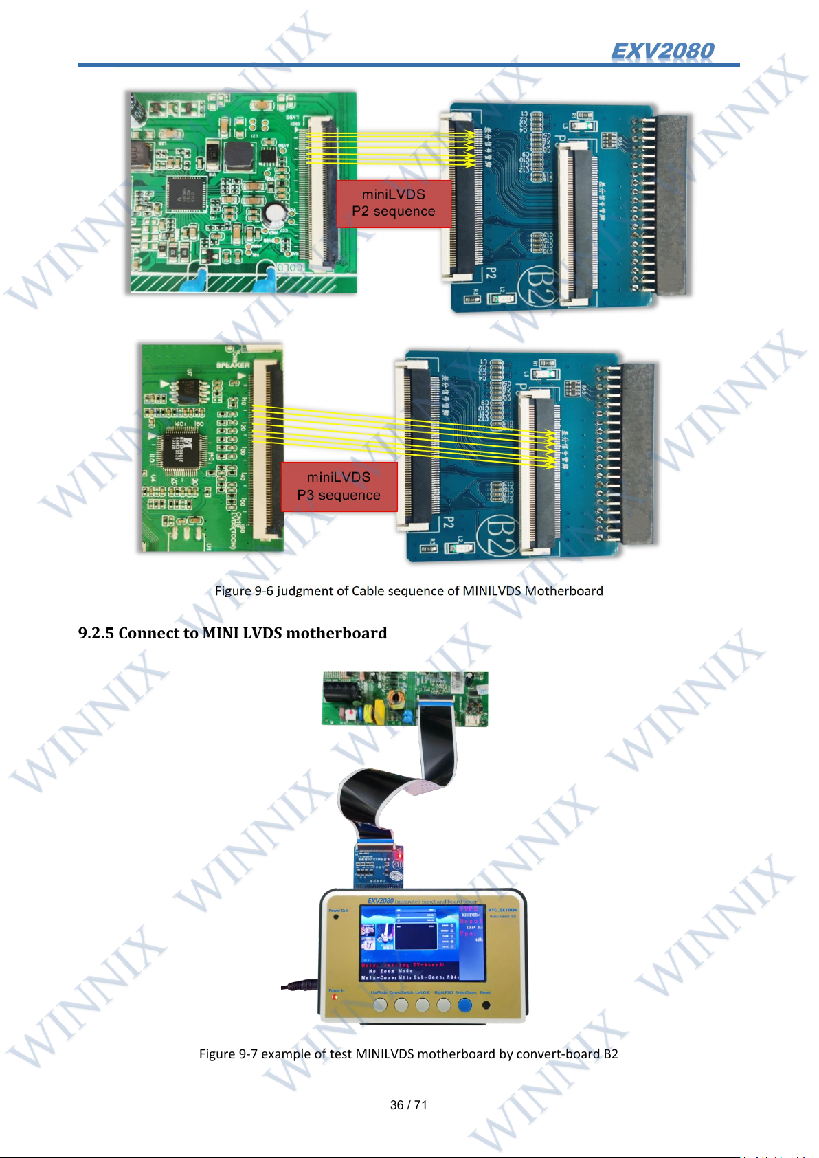
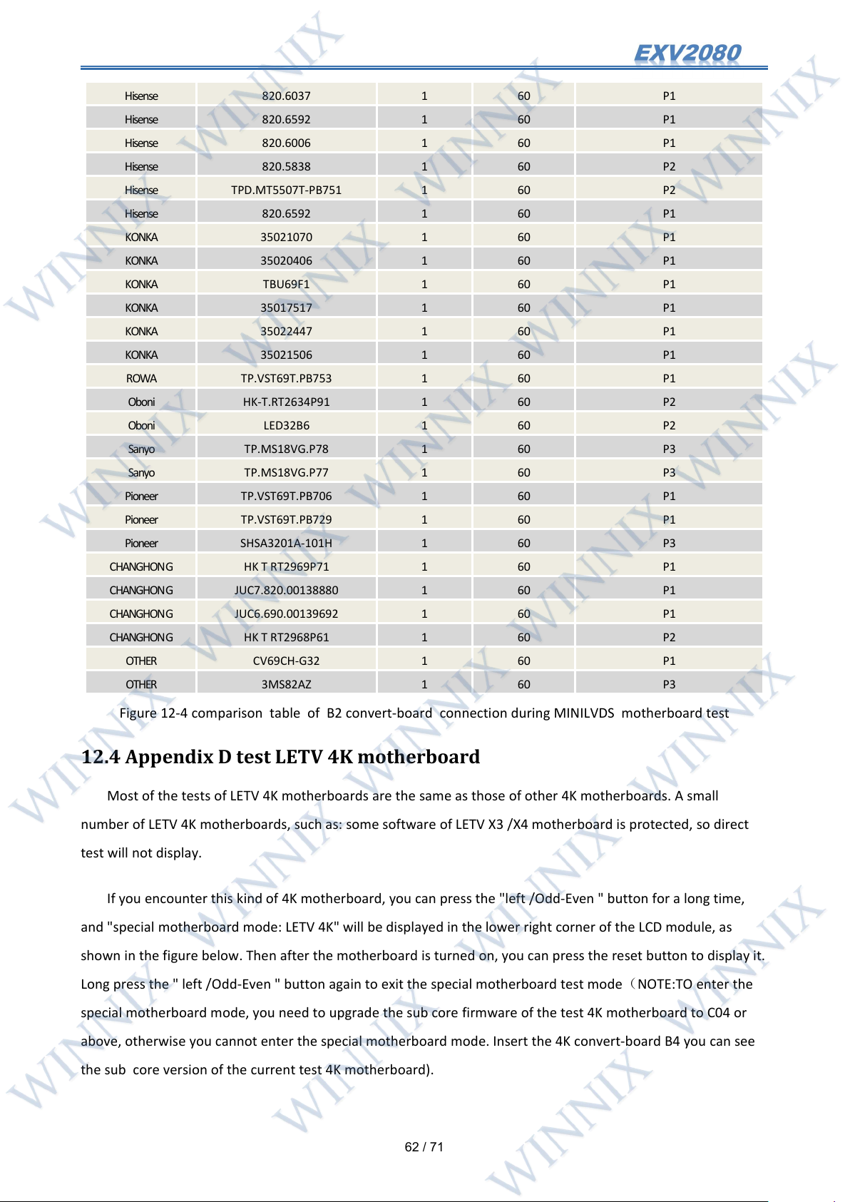
MINILVDS convert-board is No. B2. There are three 60 pin sockets on the board, corresponding to three
different MINILVDS signal Cable sequences. The judgment method can be distinguished by looking up the table
《List of interfaces for testing MINILVDS motherboard》or by observing the position of differential signal Cable.
Page 37
36
/ 71
Figure 9-6 judgment of Cable sequence of MINILVDS Motherboard
9.2.5 Connect to MINI LVDS motherboard
Figure 9-7 example of test MINILVDS motherboard by convert-board B2
Page 38
37
/ 71
Note: There are many voltage pins on the Cable interface of the MINILVDS motherboard, and the voltage is from
- 10V to above 30V, so we must be very careful when connecting the convert-board. Wrong connection
may lead to exceeding the rated protection voltage of the protection circuit and causing damage to the
protection circuit. In order to ensure no connection error, when testing MINILVDS motherboard, you should
directly follow the TV motherboard model lookup table《List of interfaces for testing MINILVDS
motherboard》.
9.5.6 VBY1 Single LCD module Cable motherboard
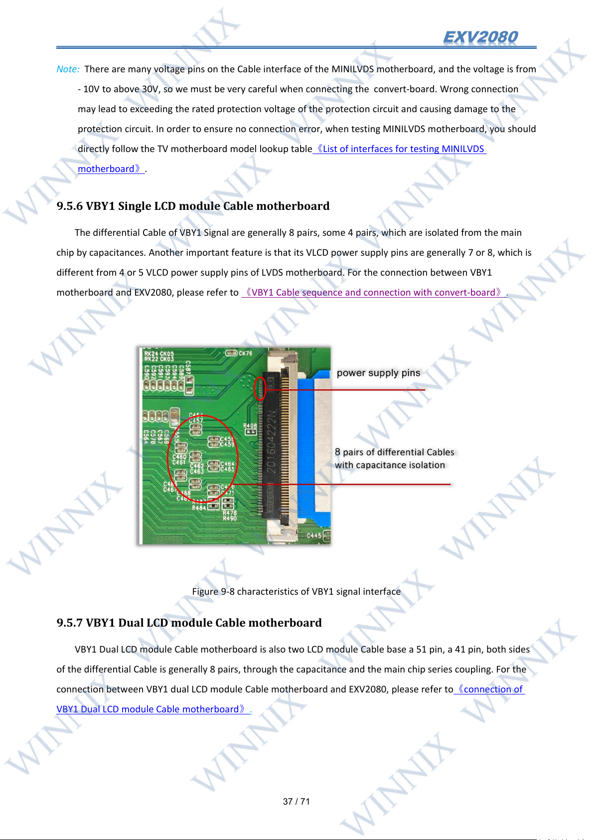
The differential Cable of VBY1 Signal are generally 8 pairs, some 4 pairs, which are isolated from the main
chip by capacitances. Another important feature is that its VLCD power supply pins are generally 7 or 8, which is
different from 4 or 5 VLCD power supply pins of LVDS motherboard. For the connection between VBY1
motherboard and EXV2080, please refer to 《VBY1 Cable sequence and connection with convert-board》.
Figure 9-8 characteristics of VBY1 signal interface
9.5.7 VBY1 Dual LCD module Cable motherboard
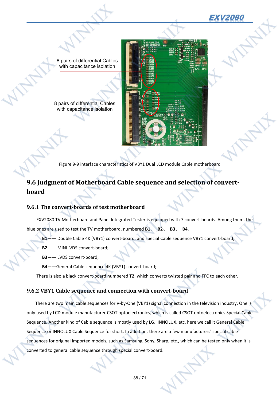
VBY1 Dual LCD module Cable motherboard is also two LCD module Cable base a 51 pin, a 41 pin, both sides
of the differential Cable is generally 8 pairs, through the capacitance and the main chip series coupling. For the
connection between VBY1 dual LCD module Cable motherboard and EXV2080, please refer to《connection of
VBY1 Dual LCD module Cable motherboard》.
Page 39
38
/ 71
Figure 9-9 interface characteristics of VBY1 Dual LCD module Cable motherboard
8 pairs of differential Cables
with capacitance isolation
8 pairs of differential Cables
with capacitance isolation
9.6 Judgment of Motherboard Cable sequence and selection of convert-
board
9.6.1 The convert-boards of test motherboard
EXV2080 TV Motherboard and Panel Integrated Tester is equipped with 7 convert-boards. Among them, the
blue ones are used to test the TV motherboard, numbered B1、 B2、 B3、 B4.
B1—— Double Cable 4K (VBY1) convert-board, and special Cable sequence VBY1 convert-board;
B2—— MINILVDS convert-board;
B3—— LVDS convert-board;
B4——General Cable sequence 4K (VBY1) convert-board;
There is also a black convert-board numbered T2, which converts twisted pair and FFC to each other.
9.6.2 VBY1 Cable sequence and connection with convert-board
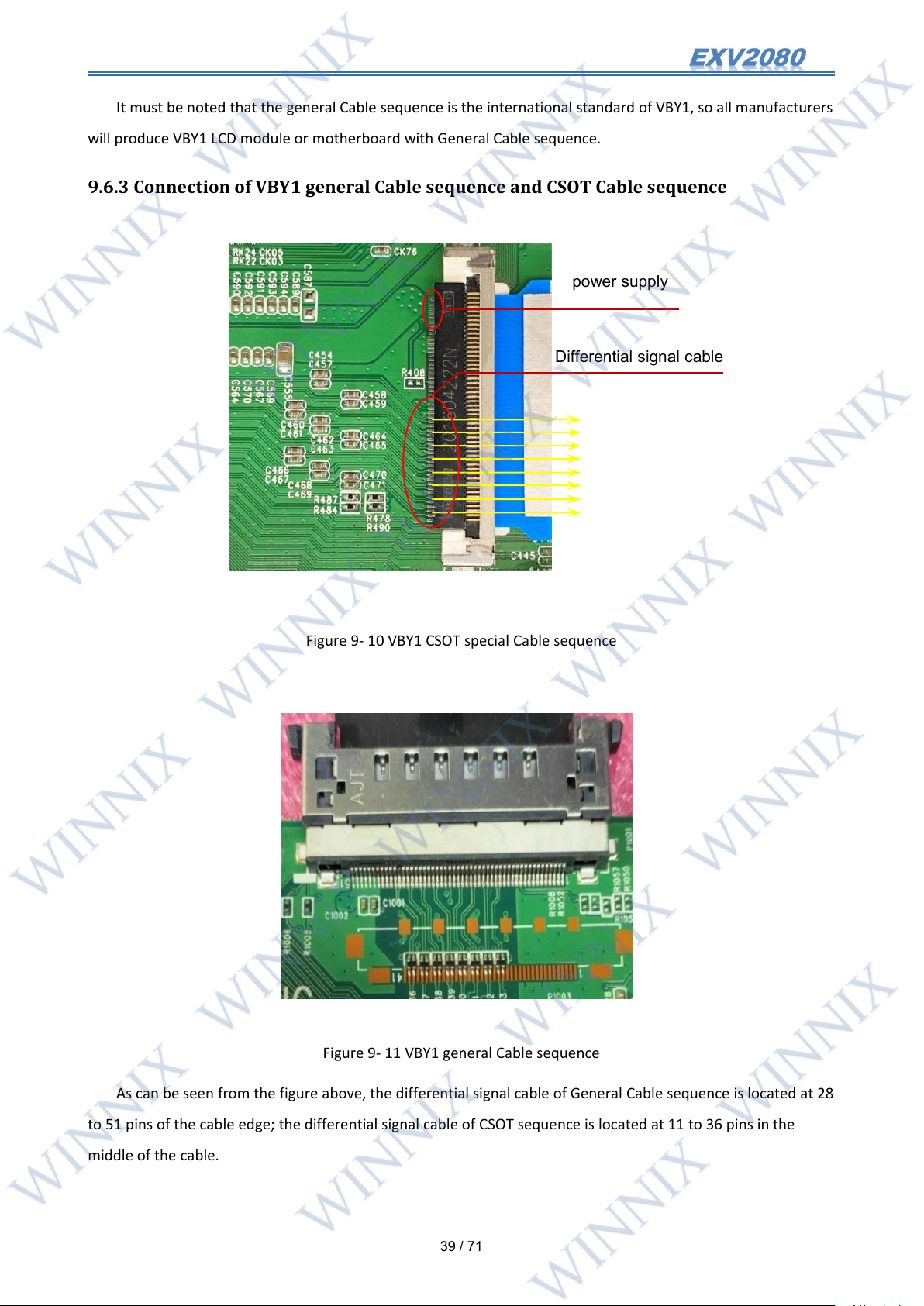
There are two main cable sequences for V-by-One (VBY1) signal connection in the television industry, One is
only used by LCD module manufacturer CSOT optoelectronics, which is called CSOT optoelectronics Special Cable
Sequence. Another kind of Cable sequence is mostly used by LG, INNOLUX, etc, here we call it General Cable
Sequence or INNOLUX Cable Sequence for short. In addition, there are a few manufacturers' special cable
sequences for original imported models, such as Samsung, Sony, Sharp, etc., which can be tested only when it is
converted to general cable sequence through special convert-board.
Page 40
39
/ 71
It must be noted that the general Cable sequence is the international standard of VBY1, so all manufacturers
Differential signal cable
power supply
will produce VBY1 LCD module or motherboard with General Cable sequence.
9.6.3 Connection of VBY1 general Cable sequence and CSOT Cable sequence
Figure 9- 10 VBY1 CSOT special Cable sequence
Figure 9- 11 VBY1 general Cable sequence
As can be seen from the figure above, the differential signal cable of General Cable sequence is located at 28
to 51 pins of the cable edge; the differential signal cable of CSOT sequence is located at 11 to 36 pins in the
middle of the cable.
Page 41
40
/ 71
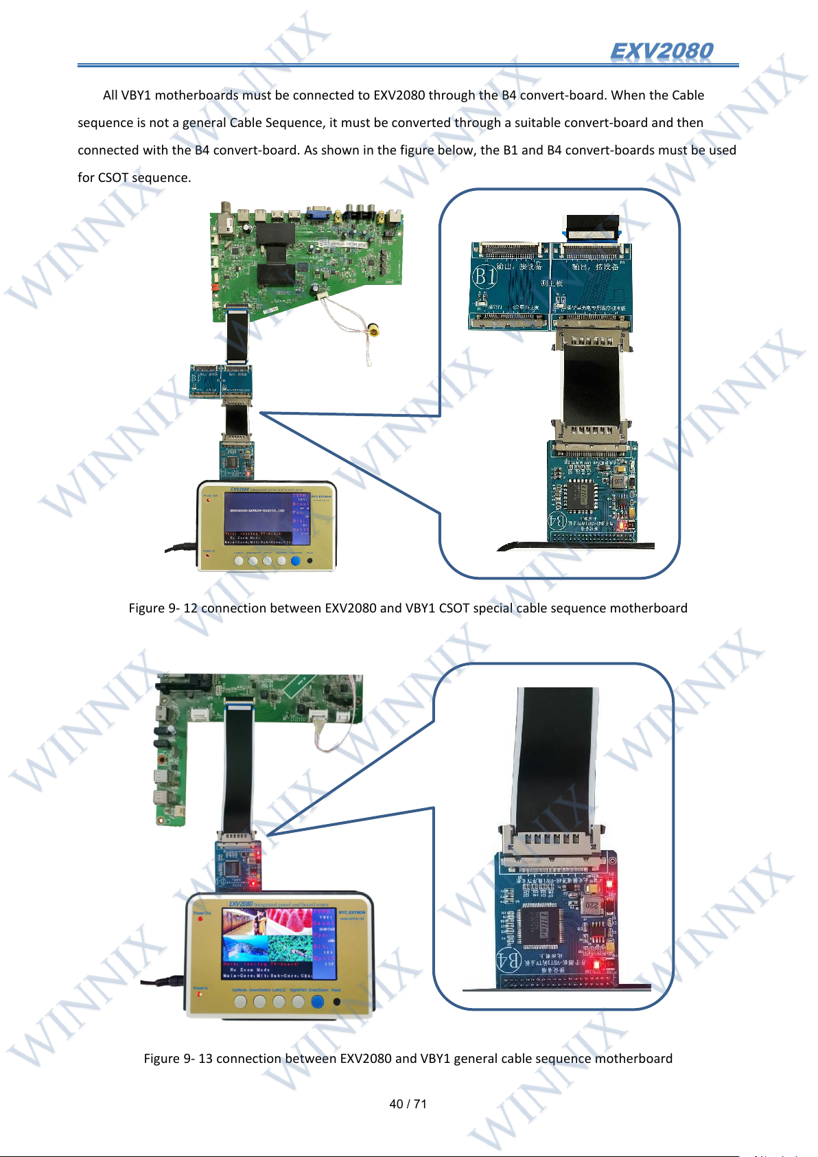
All VBY1 motherboards must be connected to EXV2080 through the B4 convert-board. When the Cable
sequence is not a general Cable Sequence, it must be converted through a suitable convert-board and then
connected with the B4 convert-board. As shown in the figure below, the B1 and B4 convert-boards must be used
for CSOT sequence.
Figure 9- 12 connection between EXV2080 and VBY1 CSOT special cable sequence motherboard
Figure 9- 13 connection between EXV2080 and VBY1 general cable sequence motherboard
Page 42
41
/ 71
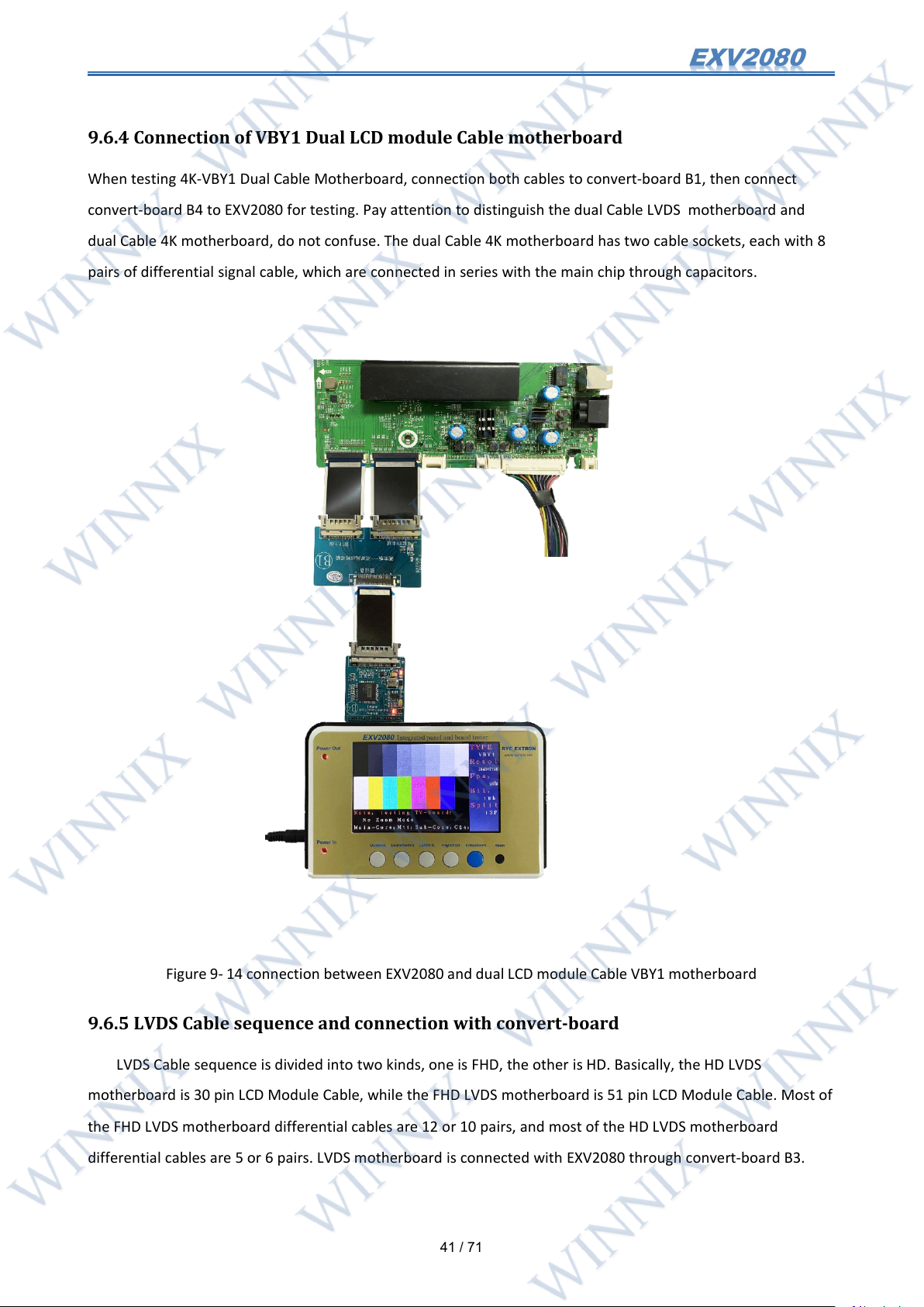
9.6.4 Connection of VBY1 Dual LCD module Cable motherboard
When testing 4K-VBY1 Dual Cable Motherboard, connection both cables to convert-board B1, then connect
convert-board B4 to EXV2080 for testing. Pay attention to distinguish the dual Cable LVDS motherboard and
dual Cable 4K motherboard, do not confuse. The dual Cable 4K motherboard has two cable sockets, each with 8
pairs of differential signal cable, which are connected in series with the main chip through capacitors.
Figure 9- 14 connection between EXV2080 and dual LCD module Cable VBY1 motherboard
9.6.5 LVDS Cable sequence and connection with convert-board
LVDS Cable sequence is divided into two kinds, one is FHD, the other is HD. Basically, the HD LVDS
motherboard is 30 pin LCD Module Cable, while the FHD LVDS motherboard is 51 pin LCD Module Cable. Most of
the FHD LVDS motherboard differential cables are 12 or 10 pairs, and most of the HD LVDS motherboard
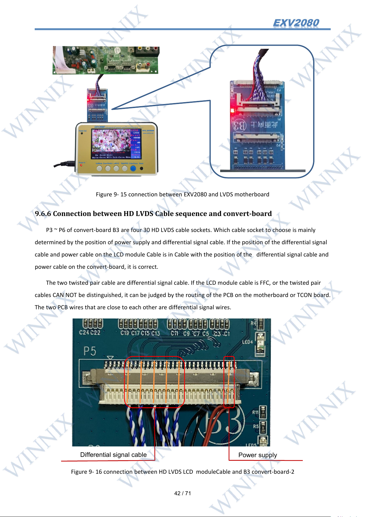
differential cables are 5 or 6 pairs. LVDS motherboard is connected with EXV2080 through convert-board B3.
Page 43
42
/ 71
Figure 9- 15 connection between EXV2080 and LVDS motherboard
Differential signal cable
Power supply
9.6.6 Connection between HD LVDS Cable sequence and convert-board
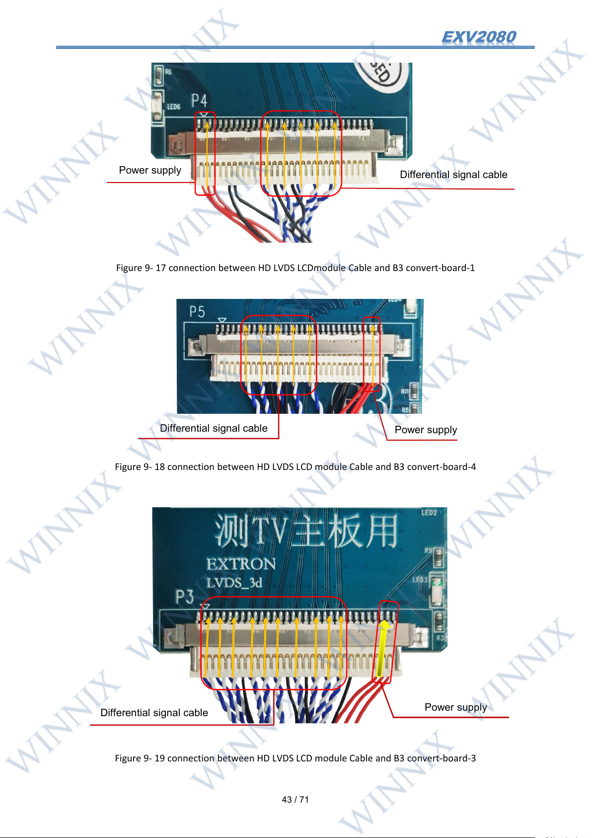
P3 ~ P6 of convert-board B3 are four 30 HD LVDS cable sockets. Which cable socket to choose is mainly
determined by the position of power supply and differential signal cable. If the position of the differential signal
cable and power cable on the LCD module Cable is in Cable with the position of the differential signal cable and
power cable on the convert-board, it is correct.
The two twisted pair cable are differential signal cable. If the LCD module cable is FFC, or the twisted pair
cables CAN NOT be distinguished, it can be judged by the routing of the PCB on the motherboard or TCON board.
The two PCB wires that are close to each other are differential signal wires.
Figure 9- 16 connection between HD LVDS LCD moduleCable and B3 convert-board-2
Page 44
43
/ 71
Figure 9- 17 connection between HD LVDS LCDmodule Cable and B3 convert-board-1
Differential signal cable
Power supply
Power supply
Differential signal cable
Power supply
Differential signal cable
Figure 9- 18 connection between HD LVDS LCD module Cable and B3 convert-board-4
Figure 9- 19 connection between HD LVDS LCD module Cable and B3 convert-board-3
Page 45
44
/ 71
9.6.7 Connection FHD LVDS Cable sequence and convert-board
Power supply
Differential signal cable
Differential signal cable
Power supply
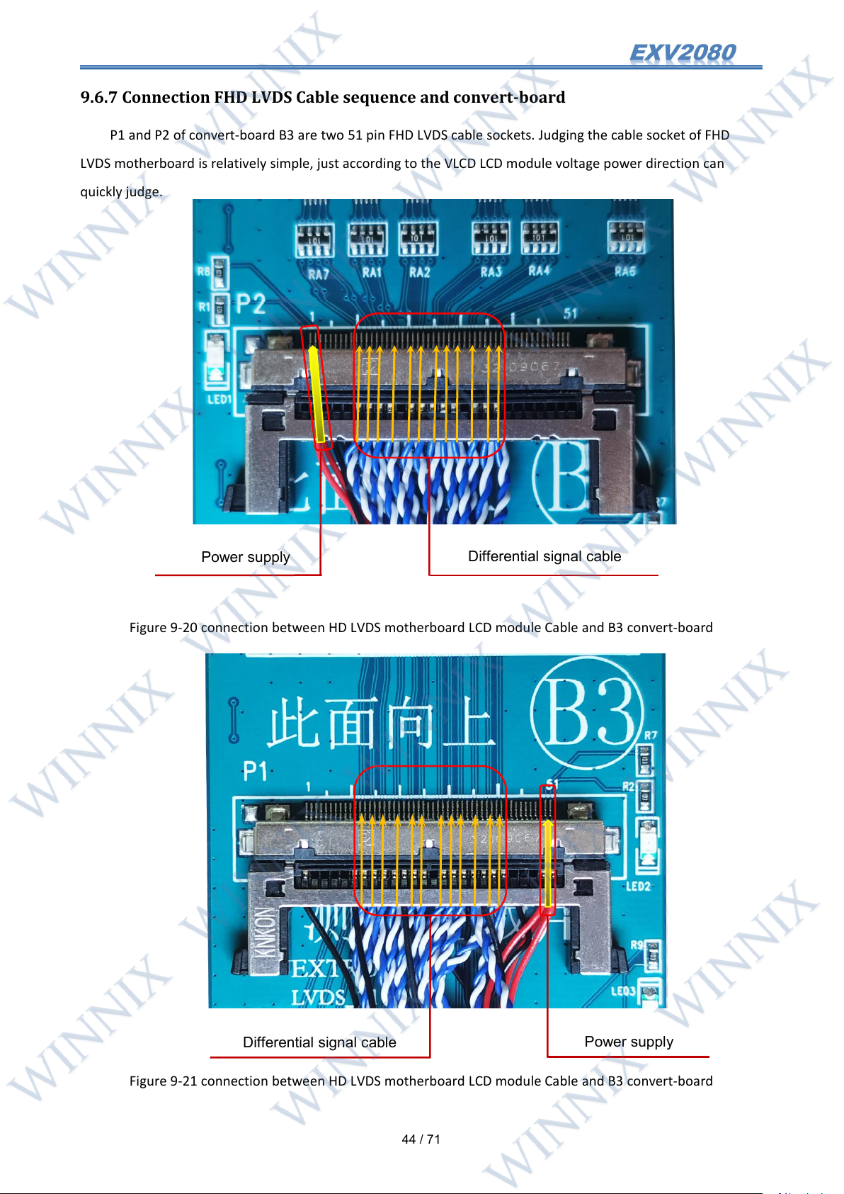
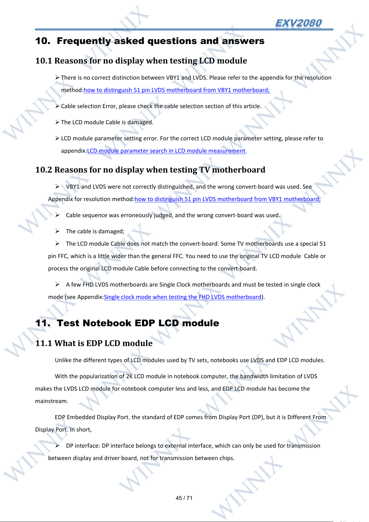
P1 and P2 of convert-board B3 are two 51 pin FHD LVDS cable sockets. Judging the cable socket of FHD
LVDS motherboard is relatively simple, just according to the VLCD LCD module voltage power direction can
quickly judge.
Figure 9-20 connection between HD LVDS motherboard LCD module Cable and B3 convert-board
Figure 9-21 connection between HD LVDS motherboard LCD module Cable and B3 convert-board
Page 46
45
/ 71
10. Frequently asked questions and answers
10.1 Reasons for no display when testing LCD module
There is no correct distinction between VBY1 and LVDS. Please refer to the appendix for the resolution
method:how to distinguish 51 pin LVDS motherboard from VBY1 motherboard;
Cable selection Error, please check the cable selection section of this article.
The LCD module Cable is damaged.
LCD module parameter setting error. For the correct LCD module parameter setting, please refer to
appendix:LCD module parameter search in LCD module measurement.
10.2 Reasons for no display when testing TV motherboard
VBY1 and LVDS were not correctly distinguished, and the wrong convert-board was used. See
Appendix for resolution method:how to distinguish 51 pin LVDS motherboard from VBY1 motherboard;
Cable sequence was erroneously judged, and the wrong convert-board was used.
The cable is damaged;
The LCD module Cable does not match the convert-board. Some TV motherboards use a special 51
pin FFC, which is a little wider than the general FFC. You need to use the original TV LCD module Cable or
process the original LCD module Cable before connecting to the convert-board.
A few FHD LVDS motherboards are Single Clock motherboards and must be tested in single clock
mode (see Appendix:Single clock mode when testing the FHD LVDS motherboard).
11. Test Notebook EDP LCD module
11.1 What is EDP LCD module
Unlike the different types of LCD modules used by TV sets, notebooks use LVDS and EDP LCD modules.
With the popularization of 2K LCD module in notebook computer, the bandwidth limitation of LVDS
makes the LVDS LCD module for notebook computer less and less, and EDP LCD module has become the
mainstream.
EDP Embedded Display Port. the standard of EDP comes from Display Port (DP), but it is Different From
Display Port. In short,
DP interface: DP interface belongs to external interface, which can only be used for transmission
between display and driver board, not for transmission between chips.
Page 47
46
/ 71
EDP interface: EDP interface is an internal interface, which can be used for the transmission between
chips, or between display and driver board.
EXV2080 supports edp1.1 standard, and EDP version is downward compatible. Here we only discuss how
to test EDP LCD module with EXV2080.
EXV2080 can be used with EDP convert-board E1 (to be purchased separately) to realize the test of
notebook EDP LCD module.
Note: DP interface looks very similar to EDP interface in appearance, but DP is only used for large display
LCD module, DP LCD module is not used for notebook. When you encounter a large LCD module, that is, a LCD
module of more than 16 inches, do not use the EDP of EXV2080 to test.
Note: Due to the fact that EDP LCD module is mostly used in notebook computers, it is suggested to use
EXV2080 for EDP LCD module test on the premise that users should be familiar with the maintenance of notebook
computers and have a deeper understanding of notebook LCD module.
11.2 Features of test EDP LCD module with EXV2080
Compared with similar products on the market, EXV2080 test notebook EDP LCD module has the following
characteristics:
Built in 12V power supply and backlight control circuit, for the mainstream LED backlight EDP LCD
module, there is no need to add additional backlight power supply;
The built-in SMBUS control circuit can directly light up the EDP LCD module with SMBUS control
backlight;
The LCD module parameter setting of EDP is intuitive and visual, and the LCD module parameter
covers the current mainstream 8 resolutions. The LCD module parameters are directly set in the user
interface of the instrument without additional resistance and jumper;
It can directly test the mainstream 30 pin and 40 pin general EDP cable sequence LCD module,
without the need to change the cable through the convert-board or twisted cable;
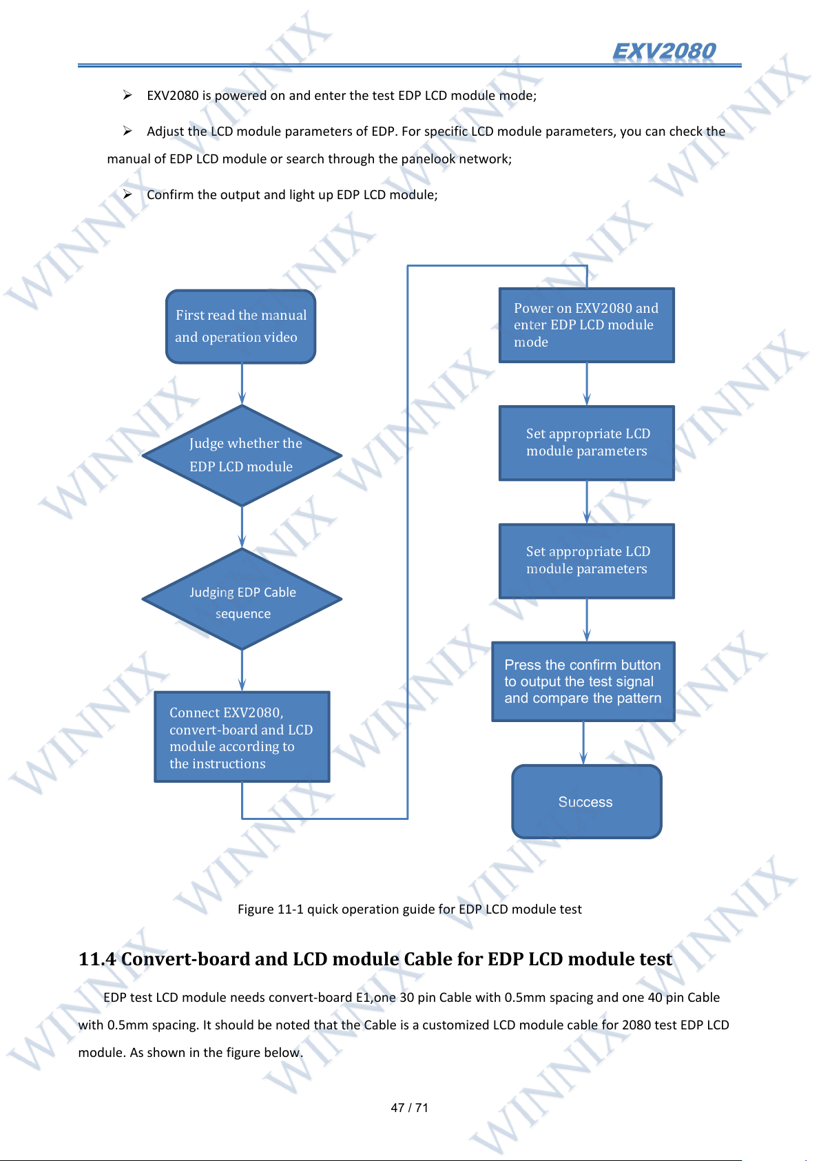
11.3 Quick operation guide
After watching the instructions and operation video;
First, judge whether the LCD module to be tested is EDP LCD module. At present, the EDP LCD
module is mostly used in notebooks, so we only need to distinguish it from the LVDS LCD module;
Judge the Cable sequence of EDP LCD module;
Connect EXV2080, convert-board E1 and EDP LCD module to be tested ;
Page 48
47
/ 71
EXV2080 is powered on and enter the test EDP LCD module mode;
Power on EXV2080 and
enter EDP LCD module
mode
Set appropriate LCD
module parameters
Set appropriate LCD
module parameters
Press the confirm button
to output the test signal
and compare the pattern
Success
First read the manual
and operation video
Judge whether the
EDP LCD module
Judging EDP Cable
sequence
Connect EXV2080,
convert-board and LCD
module according to
the instructions
Adjust the LCD module parameters of EDP. For specific LCD module parameters, you can check the
manual of EDP LCD module or search through the panelook network;
Confirm the output and light up EDP LCD module;
11.4 Convert-board and LCD module Cable for EDP LCD module test
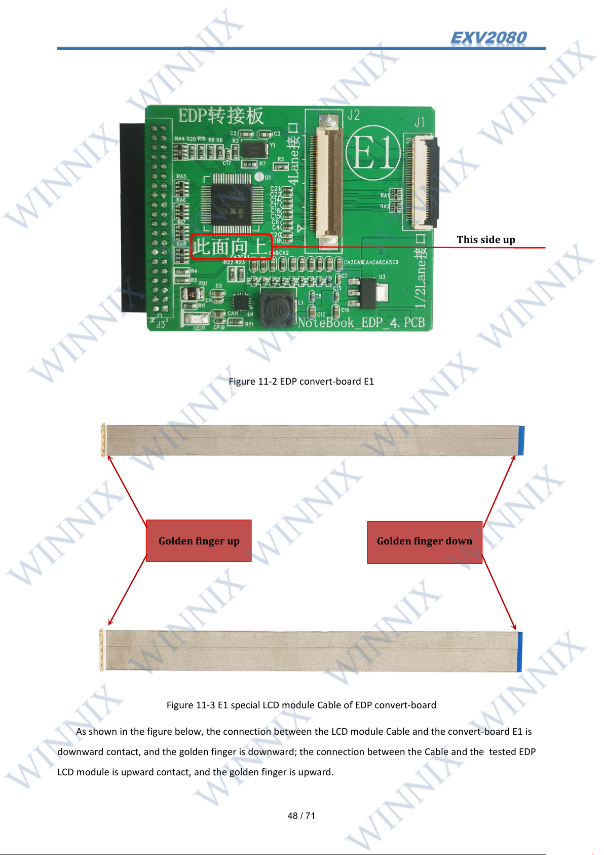
EDP test LCD module needs convert-board E1,one 30 pin Cable with 0.5mm spacing and one 40 pin Cable
with 0.5mm spacing. It should be noted that the Cable is a customized LCD module cable for 2080 test EDP LCD
module. As shown in the figure below.
Figure 11-1 quick operation guide for EDP LCD module test
Page 49
48
/ 71
Figure 11-2 EDP convert-board E1
This side up
Golden finger down
Golden finger up
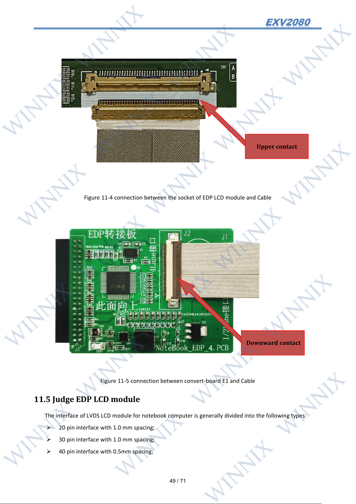
As shown in the figure below, the connection between the LCD module Cable and the convert-board E1 is
downward contact, and the golden finger is downward; the connection between the Cable and the tested EDP
LCD module is upward contact, and the golden finger is upward.
Figure 11-3 E1 special LCD module Cable of EDP convert-board
Page 50
49
/ 71
Figure 11-4 connection between the socket of EDP LCD module and Cable
Downward contact
Upper contact
11.5 Judge EDP LCD module
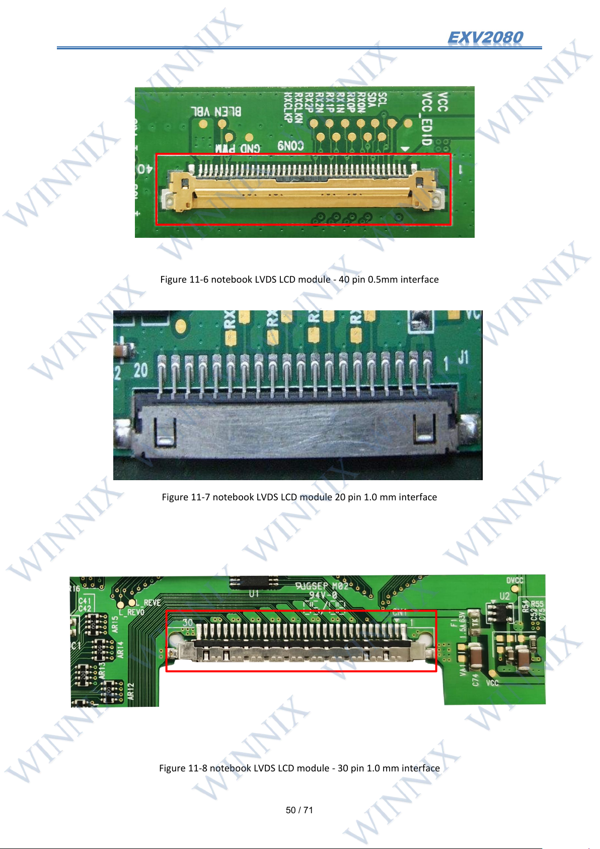
The interface of LVDS LCD module for notebook computer is generally divided into the following types:
Figure 11-5 connection between convert-board E1 and Cable
20 pin interface with 1.0 mm spacing;
30 pin interface with 1.0 mm spacing;
40 pin interface with 0.5mm spacing;
Page 51
50
/ 71
Figure 11-6 notebook LVDS LCD module - 40 pin 0.5mm interface
Figure 11-7 notebook LVDS LCD module 20 pin 1.0 mm interface
Figure 11-8 notebook LVDS LCD module - 30 pin 1.0 mm interface
Page 52
51
/ 71
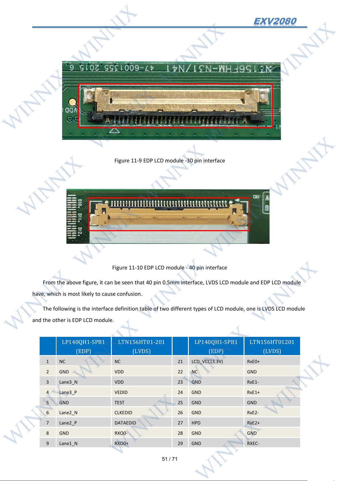
Figure 11-9 EDP LCD module -30 pin interface
LP140QH1-SPB1
(EDP)
LTN156HT01-201
(LVDS)
LP140QH1-SPB1
(EDP)
LTN156HT01201
(LVDS)
1NCNC21LCD_VCC(3.3V)
RxE0+
2
GND
VDD22NC
GND
3
Lane3_N
VDD23GND
RxE1-
4
Lane3_P
VEDID
24
GND
RxE1+
5
GND
TEST25GND
GND
6
Lane2_N
CLKEDID
26
GND
RxE2-
7
Lane2_P
DATAEDID
27
HPD
RxE2+
8
GND
RXO0-
28
GND
GND9Lane1_N
RXO0+
29
GND
RXEC-
Figure 11-10 EDP LCD module - 40 pin interface
From the above figure, it can be seen that 40 pin 0.5mm interface, LVDS LCD module and EDP LCD module
have, which is most likely to cause confusion.
The following is the interface definition table of two different types of LCD module, one is LVDS LCD module
and the other is EDP LCD module.
Page 53
52
/ 71
10
Lane1_P
GND30GND
RXEC+
11
GND
RXO1-
31
GND
GND
12
Lane0_N
RXO1+
32
BL_EN
GND
13
Lane0_P
GND33BL_PWM
GND
14
GND
RXO2-
34NCNC
15
AUX_CH_P
RXO2+
35NCLED_PWM
16
AUX_CH_N
GND36VBL(12V)
LED_EN
17
GND
RXOC-
37
VBL(12V)
NC
18
LCD_VCC(3.3V)
RXOC+
38
VBL(12V)
VBL(12V)
19
LCD_VCC(3.3V)
GND39VBL(12V)
VBL(12V)
20
LCD_VCC(3.3V)
RxE0-
40NCVBL(12V)
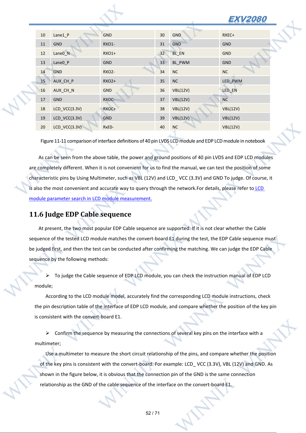
Figure11-11comparisonof interfacedefinitions of 40pinLVDSLCD moduleandEDP LCDmoduleinnotebook
As can be seen from the above table, the power and ground positions of 40 pin LVDS and EDP LCD modules
are completely different. When it is not convenient for us to find the manual, we can test the position of some
characteristic pins by Using Multimeter, such as VBL (12V) and LCD_ VCC (3.3V) and GND To judge. Of course, it
is also the most convenient and accurate way to query through the network.For details, please refer to LCD
module parameter search in LCD module measurement.
11.6 Judge EDP Cable sequence
At present, the two most popular EDP Cable sequence are supported. If it is not clear whether the Cable
sequence of the tested LCD module matches the convert-board E1 during the test, the EDP Cable sequence must
be judged first, and then the test can be conducted after confirming the matching. We can judge the EDP Cable
sequence by the following methods:
To judge the Cable sequence of EDP LCD module, you can check the instruction manual of EDP LCD
module;
According to the LCD module model, accurately find the corresponding LCD module instructions, check
the pin description table of the interface of EDP LCD module, and compare whether the position of the key pin
is consistent with the convert-board E1.
Confirm the sequence by measuring the connections of several key pins on the interface with a
multimeter;
Use a multimeter to measure the short circuit relationship of the pins, and compare whether the position
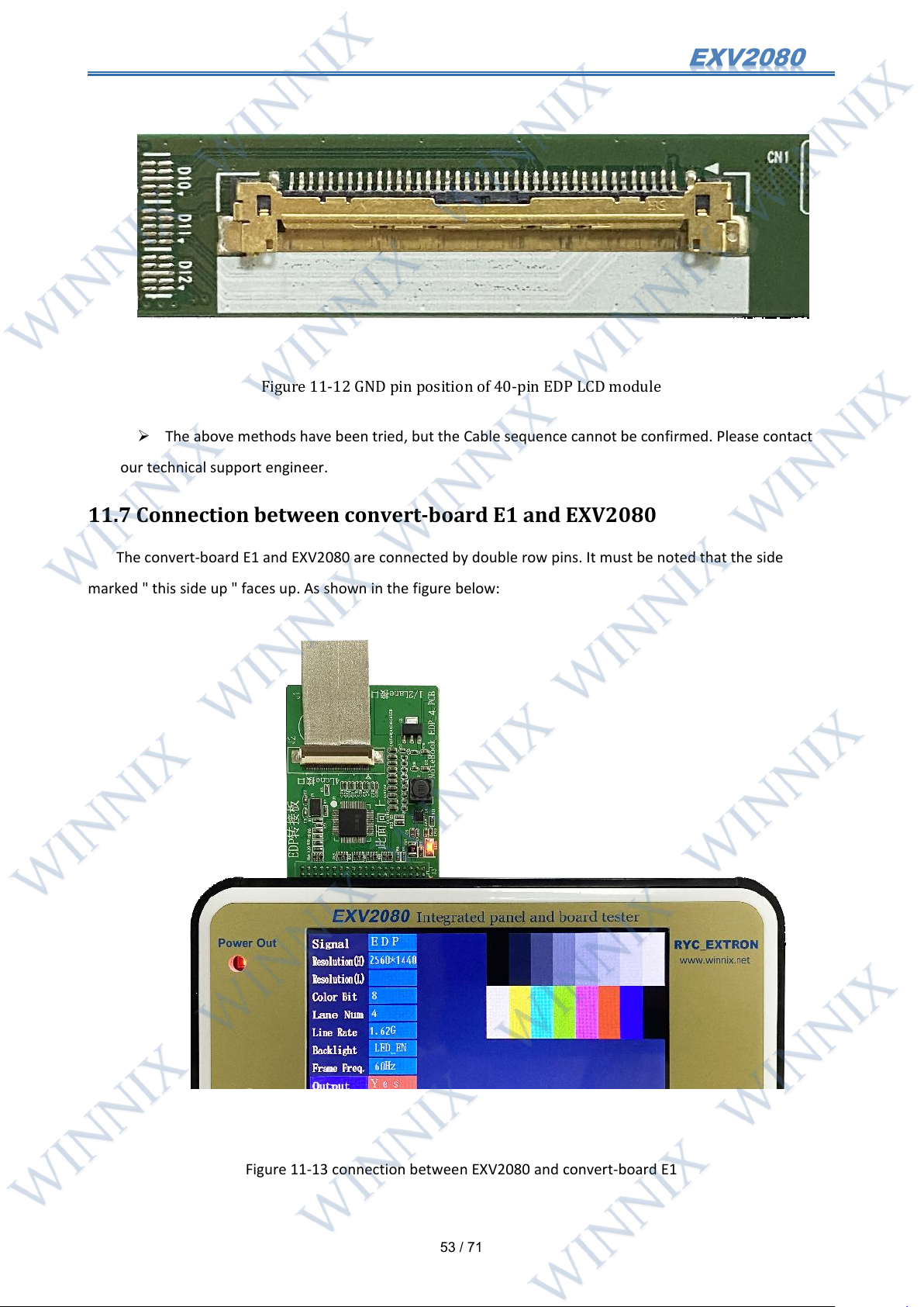
of the key pins is consistent with the convert-board. For example: LCD_ VCC (3.3V), VBL (12V) and GND. As
shown in the figure below, it is obvious that the connection pin of the GND is the same connection
relationship as the GND of the cable sequence of the interface on the convert-board E1.
Page 54
53
/ 71
Figure 11-12 GND pin position of 40-pin EDP LCD module
The above methods have been tried, but the Cable sequence cannot be confirmed. Please contact
our technical support engineer.
11.7 Connection between convert-board E1 and EXV2080
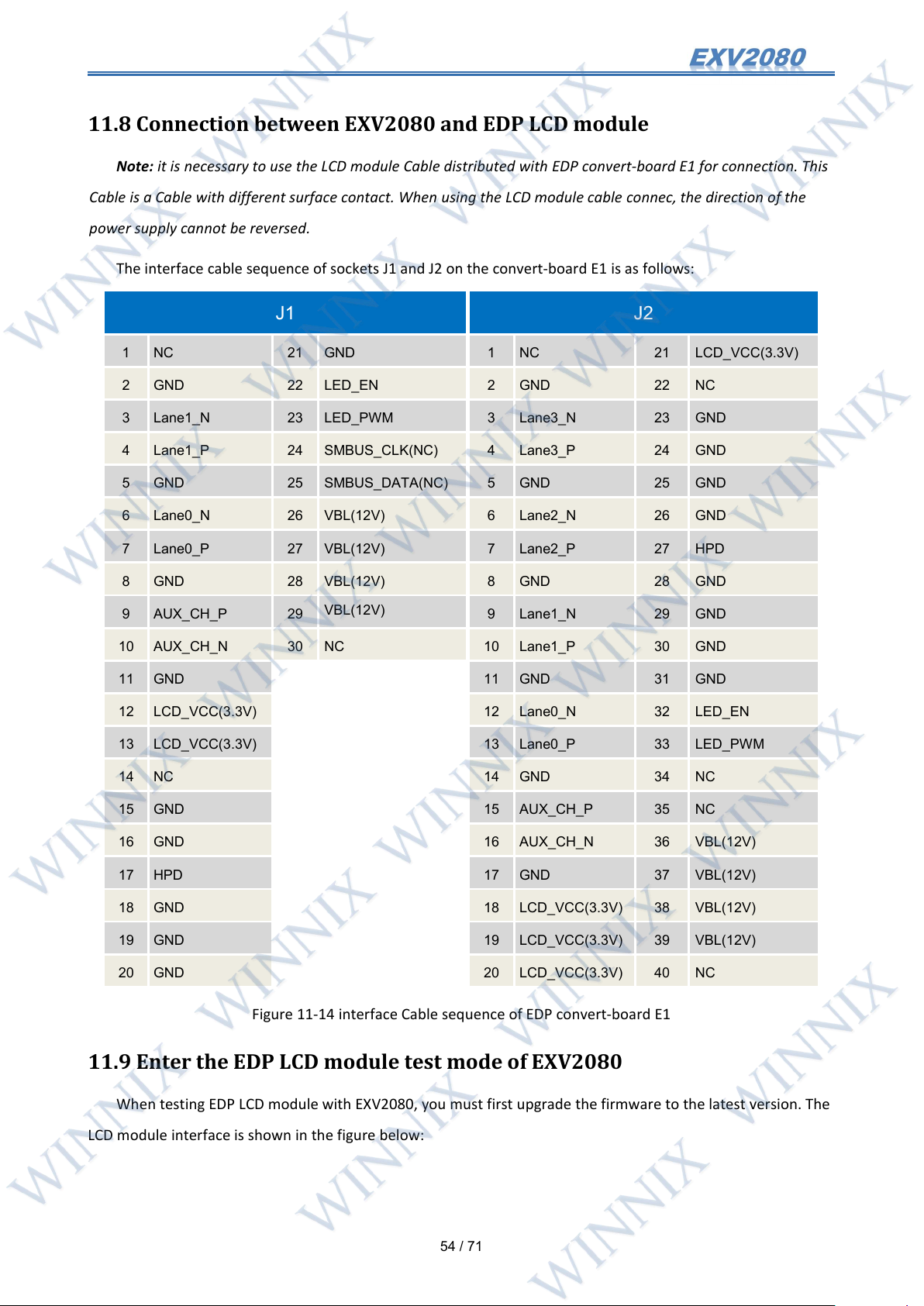
The convert-board E1 and EXV2080 are connected by double row pins. It must be noted that the side
marked " this side up " faces up. As shown in the figure below:
Figure 11-13 connection between EXV2080 and convert-board E1
Page 55
54
/ 71
11.8 Connection between EXV2080 and EDP LCD module
J1
J2
1NC21
GND
1NC21
LCD_VCC(3.3V)
2
GND22LED_EN
2
GND22NC
3
Lane1_N
23
LED_PWM
3
Lane3_N
23
GND
4
Lane1_P
24
SMBUS_CLK(NC)
4
Lane3_P
24
GND
5
GND25SMBUS_DATA(NC)
5
GND25GND
6
Lane0_N
26
VBL(12V)
6
Lane2_N
26
GND
7
Lane0_P
27
VBL(12V)
7
Lane2_P
27
HPD
8
GND28VBL(12V)
8
GND28GND
9
AUX_CH_P
29
VBL(12V)
9
Lane1_N
29
GND
10
AUX_CH_N
30NC10
Lane1_P
30
GND
11
GND11GND31GND
12
LCD_VCC(3.3V)
12
Lane0_N
32
LED_EN
13
LCD_VCC(3.3V)
13
Lane0_P
33
LED_PWM
14NC14
GND34NC
15
GND15AUX_CH_P
35
NC
16
GND16AUX_CH_N
36
VBL(12V)
17
HPD17GND37VBL(12V)
18
GND18LCD_VCC(3.3V)
38
VBL(12V)
19
GND19LCD_VCC(3.3V)
39
VBL(12V)
20
GND20LCD_VCC(3.3V)
40
NC
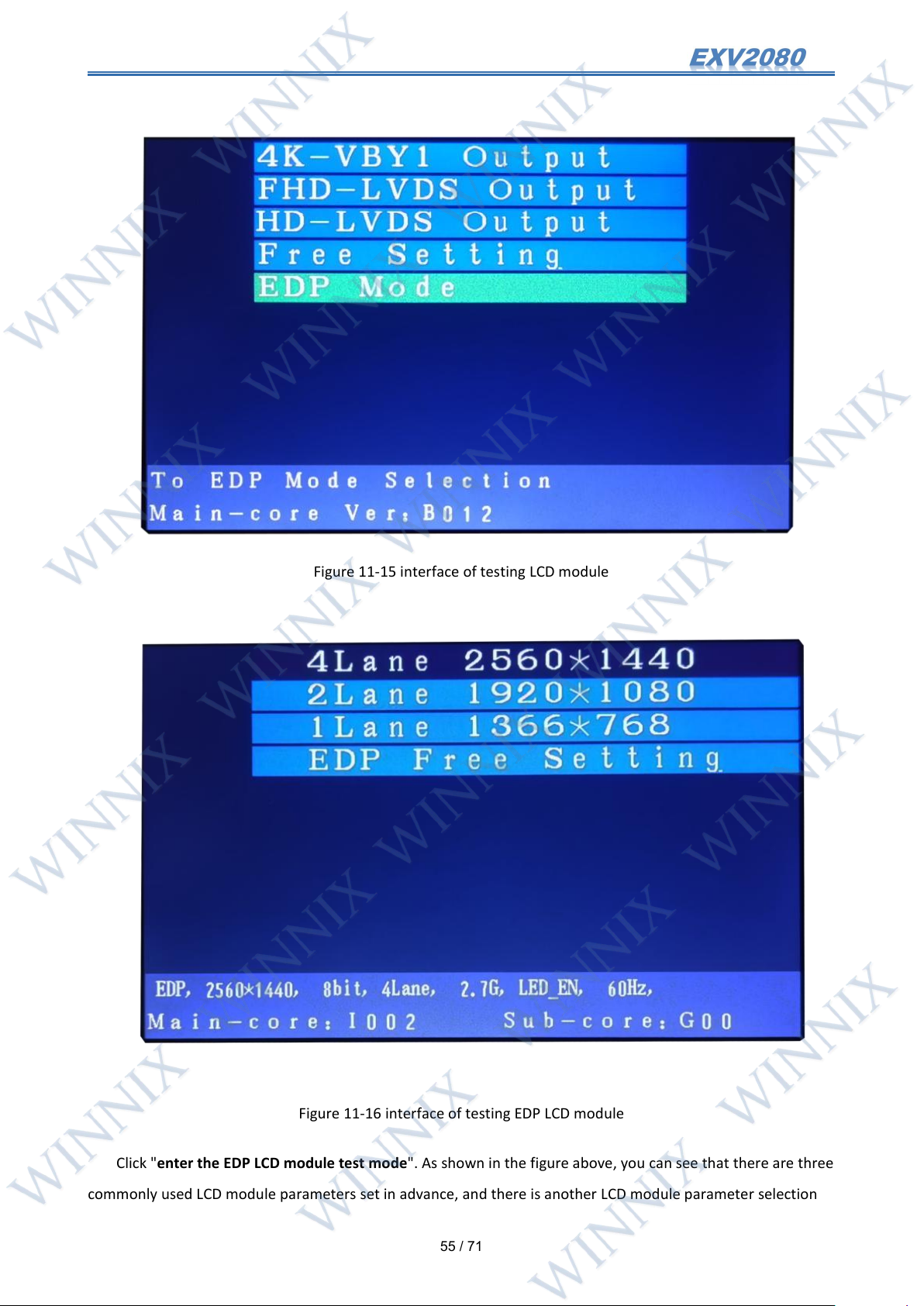
Note: it is necessary to use the LCD module Cable distributed with EDP convert-board E1 for connection. This
Cable is a Cable with different surface contact. When using the LCD module cable connec, the direction of the
power supply cannot be reversed.
The interface cable sequence of sockets J1 and J2 on the convert-board E1 is as follows:
11.9 Enter the EDP LCD module test mode of EXV2080
LCD module interface is shown in the figure below:
Figure 11-14 interface Cable sequence of EDP convert-board E1
When testing EDP LCD module with EXV2080, you must first upgrade the firmware to the latest version. The
Page 56
55
/ 71
Figure 11-15 interface of testing LCD module
Figure 11-16 interface of testing EDP LCD module
Click "enter the EDP LCD module test mode". As shown in the figure above, you can see that there are three
commonly used LCD module parameters set in advance, and there is another LCD module parameter selection
Page 57
56
/ 71
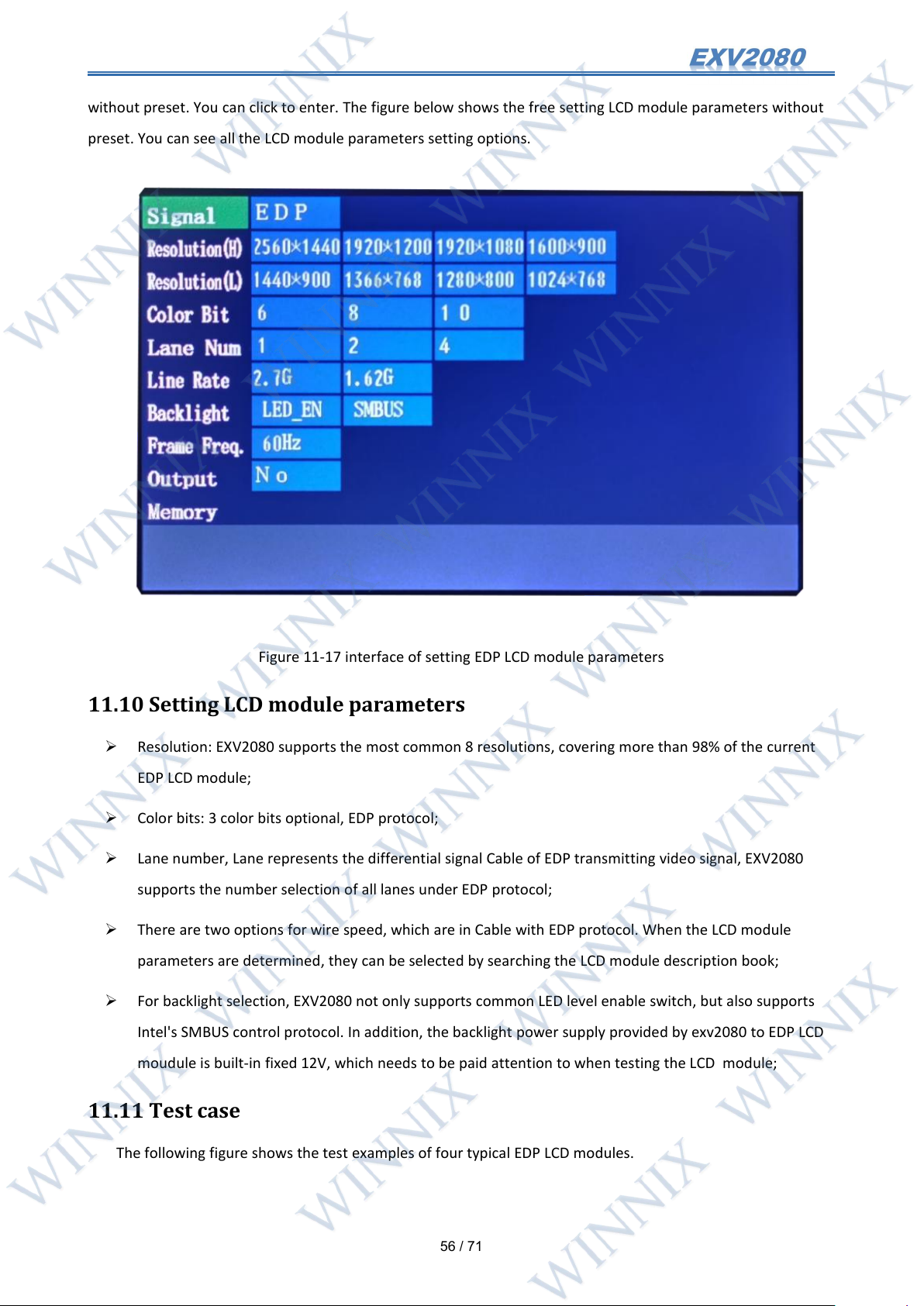
without preset. You can click to enter. The figure below shows the free setting LCD module parameters without
preset. You can see all the LCD module parameters setting options.
Figure 11-17 interface of setting EDP LCD module parameters
11.10 Setting LCD module parameters
Resolution: EXV2080 supports the most common 8 resolutions, covering more than 98% of the current
EDP LCD module;
Color bits: 3 color bits optional, EDP protocol;
Lane number, Lane represents the differential signal Cable of EDP transmitting video signal, EXV2080
supports the number selection of all lanes under EDP protocol;
There are two options for wire speed, which are in Cable with EDP protocol. When the LCD module
parameters are determined, they can be selected by searching the LCD module description book;
For backlight selection, EXV2080 not only supports common LED level enable switch, but also supports
Intel's SMBUS control protocol. In addition, the backlight power supply provided by exv2080 to EDP LCD
moudule is built-in fixed 12V, which needs to be paid attention to when testing the LCD module;
11.11 Test case
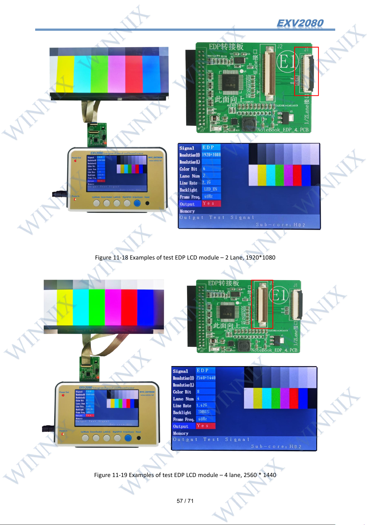
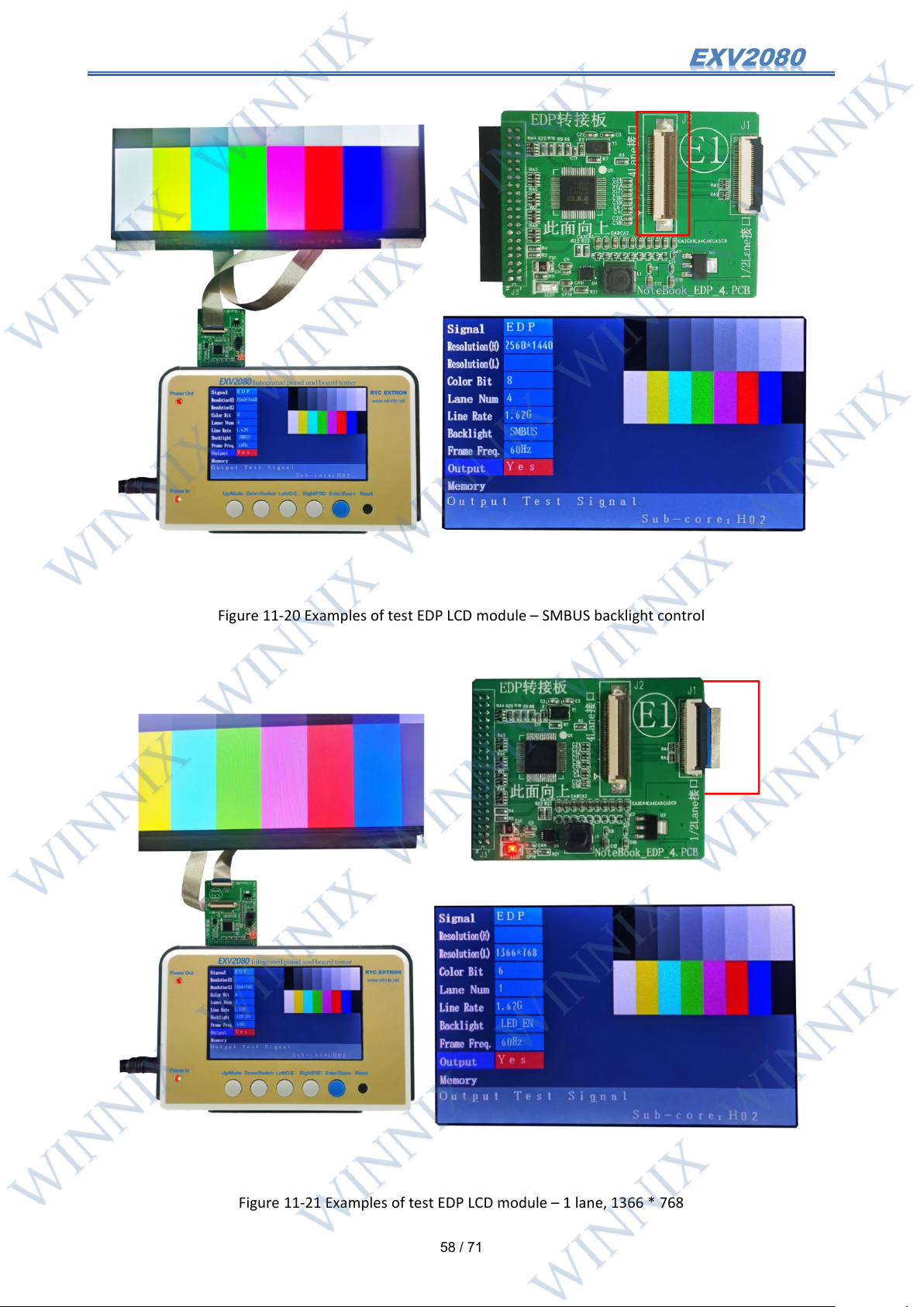
The following figure shows the test examples of four typical EDP LCD modules.
Page 58
57
/ 71
Figure 11-18 Examples of test EDP LCD module – 2 Lane, 1920*1080
Figure 11-19 Examples of test EDP LCD module – 4 lane, 2560 * 1440
Page 59
58
/ 71
Figure 11-20 Examples of test EDP LCD module – SMBUS backlight control
Figure 11-21 Examples of test EDP LCD module – 1 lane, 1366 * 768
Page 60
59
/ 71
12. Appendix
12.1 Appendix A LCD module parameter search in LCD module
measurement
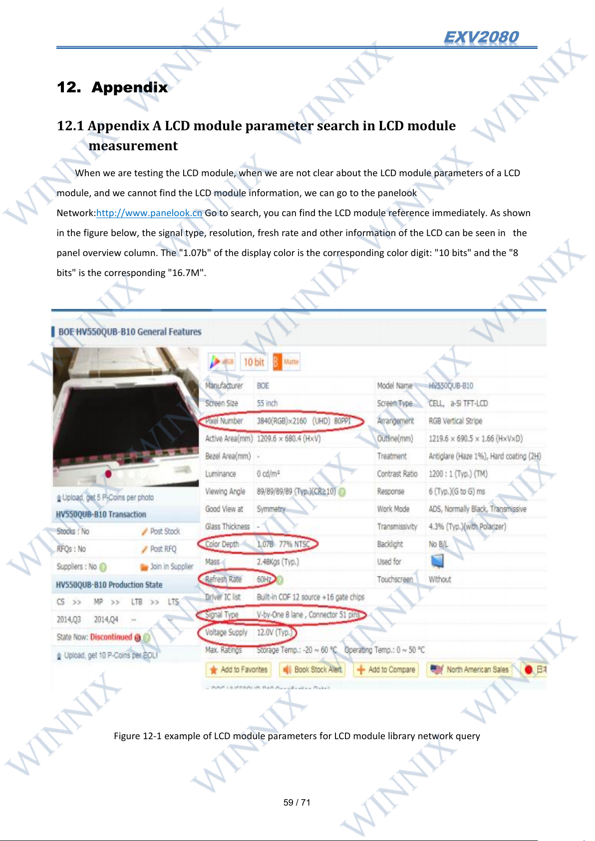
When we are testing the LCD module, when we are not clear about the LCD module parameters of a LCD
module, and we cannot find the LCD module information, we can go to the panelook
Network:http://www.panelook.cn Go to search, you can find the LCD module reference immediately. As shown
in the figure below, the signal type, resolution, fresh rate and other information of the LCD can be seen in the
panel overview column. The "1.07b" of the display color is the corresponding color digit: "10 bits" and the "8
bits" is the corresponding "16.7M".
Figure 12-1 example of LCD module parameters for LCD module library network query
Page 61
60
/ 71
12.2 Appendix B how to distinguish 51 pin LVDS motherboard from VBY1
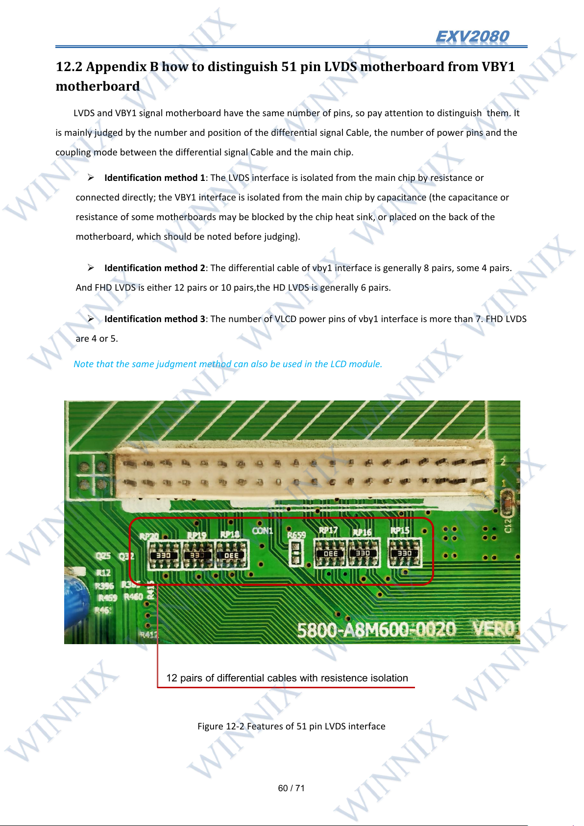
12 pairs of differential cables with resistence isolation
motherboard
LVDS and VBY1 signal motherboard have the same number of pins, so pay attention to distinguish them. It
is mainly judged by the number and position of the differential signal Cable, the number of power pins and the
coupling mode between the differential signal Cable and the main chip.
Identification method 1: The LVDS interface is isolated from the main chip by resistance or
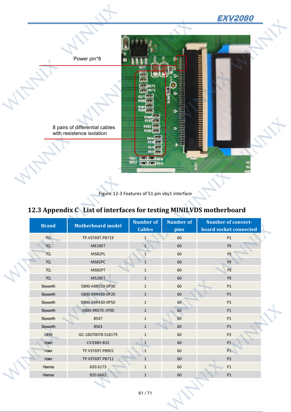
connected directly; the VBY1 interface is isolated from the main chip by capacitance (the capacitance or
resistance of some motherboards may be blocked by the chip heat sink, or placed on the back of the
motherboard, which should be noted before judging).
Identification method 2: The differential cable of vby1 interface is generally 8 pairs, some 4 pairs.
And FHD LVDS is either 12 pairs or 10 pairs,the HD LVDS is generally 6 pairs.
Identification method 3: The number of VLCD power pins of vby1 interface is more than 7. FHD LVDS
are 4 or 5.
Note that the same judgment method can also be used in the LCD module.
Figure 12-2 Features of 51 pin LVDS interface
Page 62
61
/ 71
Figure 12-3 Features of 51 pin vby1 interface
Brand
Motherboard model
Number of
Cables
Number of
pins
Number of convert-
board socket connected
TCL
TP.VST69T.PB719
1
60
P1
TCL
ME28ET
1
60
P3
TCL
MS82PL
1
60
P3
TCL
MS82PC
1
60
P3
TCL
MS82PT
1
60
P3
TCL
MS28ET
1
60
P3
Skyworth
5800-A9R010-0P30
1
60
P1
Skyworth
5800-A9R430-0P20
1
60
P1
Skyworth
5800-A9R430-0P50
1
60
P1
Skyworth
5800-9R070-1P00
1
60
P1
Skyworth
8S47
1
60
P1
Skyworth
8S63
1
60
P1
OEM
GC-16070078-S18179
1
60
P2
Haier
CV338H-B32
1
60
P1
Haier
TP.VST69T.PB901
1
60
P1
Haier
TP.VST69T.PB711
1
60
P2
Hisense
820.6173
1
60
P1
Hisense
820.6662
1
60
P1
8 pairs of differential cables
with resistence isolation
Power pin*8
12.3 Appendix C List of interfaces for testing MINILVDS motherboard
Page 63
62
/ 71
Hisense
820.6037
1
60
P1
Hisense
820.6592
1
60
P1
Hisense
820.6006
1
60
P1
Hisense
820.5838
1
60
P2
Hisense
TPD.MT5507T-PB751
1
60
P2
Hisense
820.6592
1
60
P1
KONKA
35021070
1
60
P1
KONKA
35020406
1
60
P1
KONKA
TBU69F1
1
60
P1
KONKA
35017517
1
60
P1
KONKA
35022447
1
60
P1
KONKA
35021506
1
60
P1
ROWA
TP.VST69T.PB753
1
60
P1
Oboni
HK-T.RT2634P91
1
60
P2
Oboni
LED32B6
1
60
P2
Sanyo
TP.MS18VG.P78
1
60
P3
Sanyo
TP.MS18VG.P77
1
60
P3
Pioneer
TP.VST69T.PB706
1
60
P1
Pioneer
TP.VST69T.PB729
1
60
P1
Pioneer
SHSA3201A-101H
1
60
P3
CHANGHONG
HK T RT2969P71
1
60
P1
CHANGHONG
JUC7.820.00138880
1
60
P1
CHANGHONG
JUC6.690.00139692
1
60
P1
CHANGHONG
HK T RT2968P61
1
60
P2
OTHER
CV69CH-G32
1
60
P1
OTHER
3MS82AZ
1
60
P3
Figure 12-4 comparison table of B2 convert-board connection during MINILVDS motherboard test
12.4 Appendix D test LETV 4K motherboard
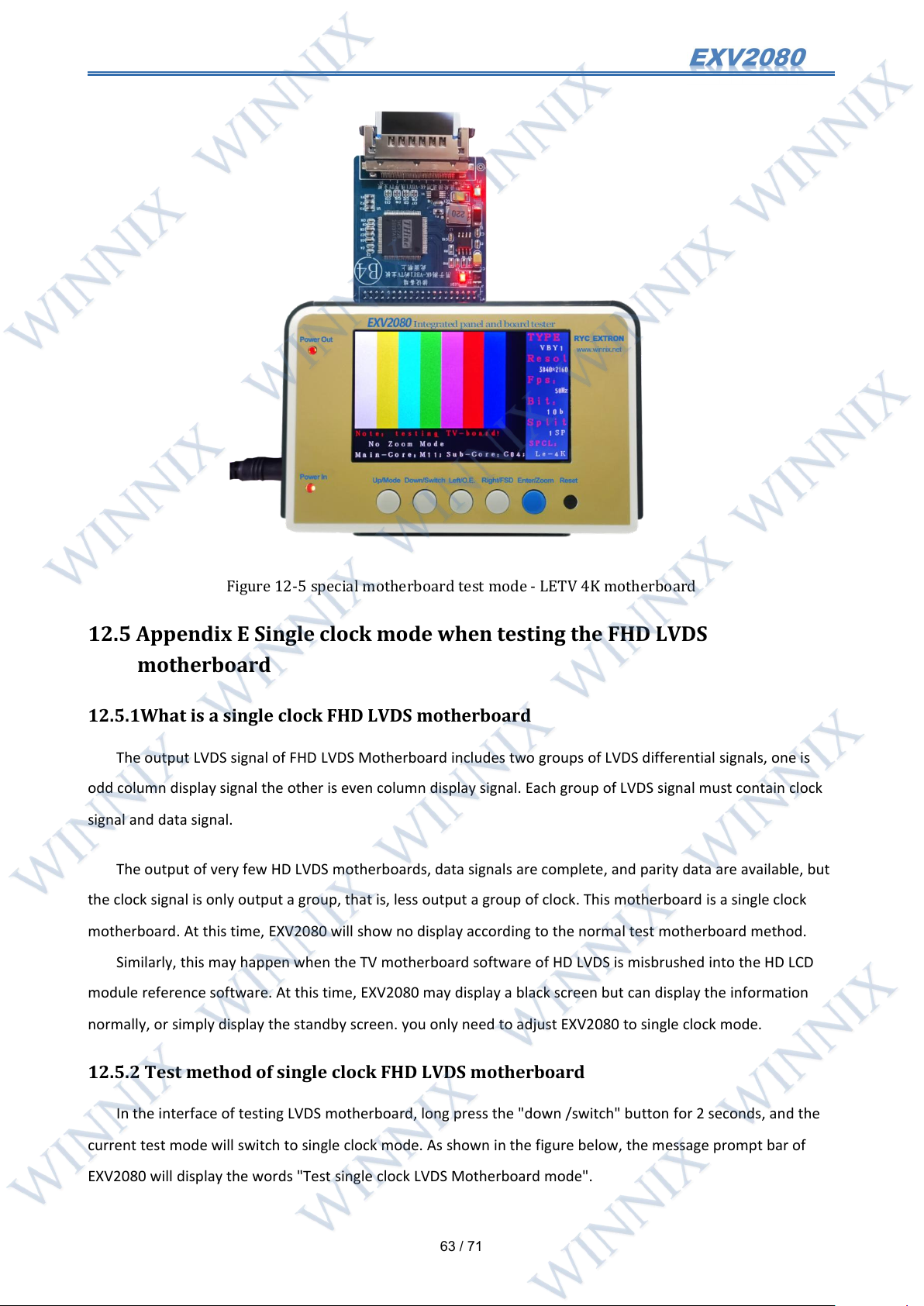
Most of the tests of LETV 4K motherboards are the same as those of other 4K motherboards. A small
number of LETV 4K motherboards, such as: some software of LETV X3 /X4 motherboard is protected, so direct
test will not display.
If you encounter this kind of 4K motherboard, you can press the "left /Odd-Even " button for a long time,
and "special motherboard mode: LETV 4K" will be displayed in the lower right corner of the LCD module, as
shown in the figure below. Then after the motherboard is turned on, you can press the reset button to display it.
Long press the " left /Odd-Even " button again to exit the special motherboard test mode(NOTE:TO enter the
special motherboard mode, you need to upgrade the sub core firmware of the test 4K motherboard to C04 or
above, otherwise you cannot enter the special motherboard mode. Insert the 4K convert-board B4 you can see
the sub core version of the current test 4K motherboard).
Page 64
63
/ 71
Figure 12-5 special motherboard test mode - LETV 4K motherboard
12.5 Appendix E Single clock mode when testing the FHD LVDS
motherboard
12.5.1What is a single clock FHD LVDS motherboard
The output LVDS signal of FHD LVDS Motherboard includes two groups of LVDS differential signals, one is
odd column display signal the other is even column display signal. Each group of LVDS signal must contain clock
signal and data signal.
The output of very few HD LVDS motherboards, data signals are complete, and parity data are available, but
the clock signal is only output a group, that is, less output a group of clock. This motherboard is a single clock
motherboard. At this time, EXV2080 will show no display according to the normal test motherboard method.
Similarly, this may happen when the TV motherboard software of HD LVDS is misbrushed into the HD LCD
module reference software. At this time, EXV2080 may display a black screen but can display the information
normally, or simply display the standby screen. you only need to adjust EXV2080 to single clock mode.
12.5.2 Test method of single clock FHD LVDS motherboard
In the interface of testing LVDS motherboard, long press the "down /switch" button for 2 seconds, and the
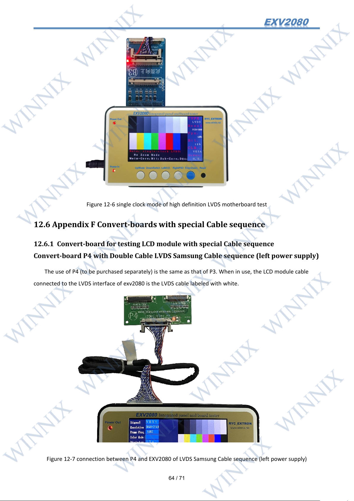
current test mode will switch to single clock mode. As shown in the figure below, the message prompt bar of
EXV2080 will display the words "Test single clock LVDS Motherboard mode".
Page 65
64
/ 71
Figure 12-6 single clock mode of high definition LVDS motherboard test
12.6 Appendix F Convert-boards with special Cable sequence
12.6.1 Convert-board for testing LCD module with special Cable sequence
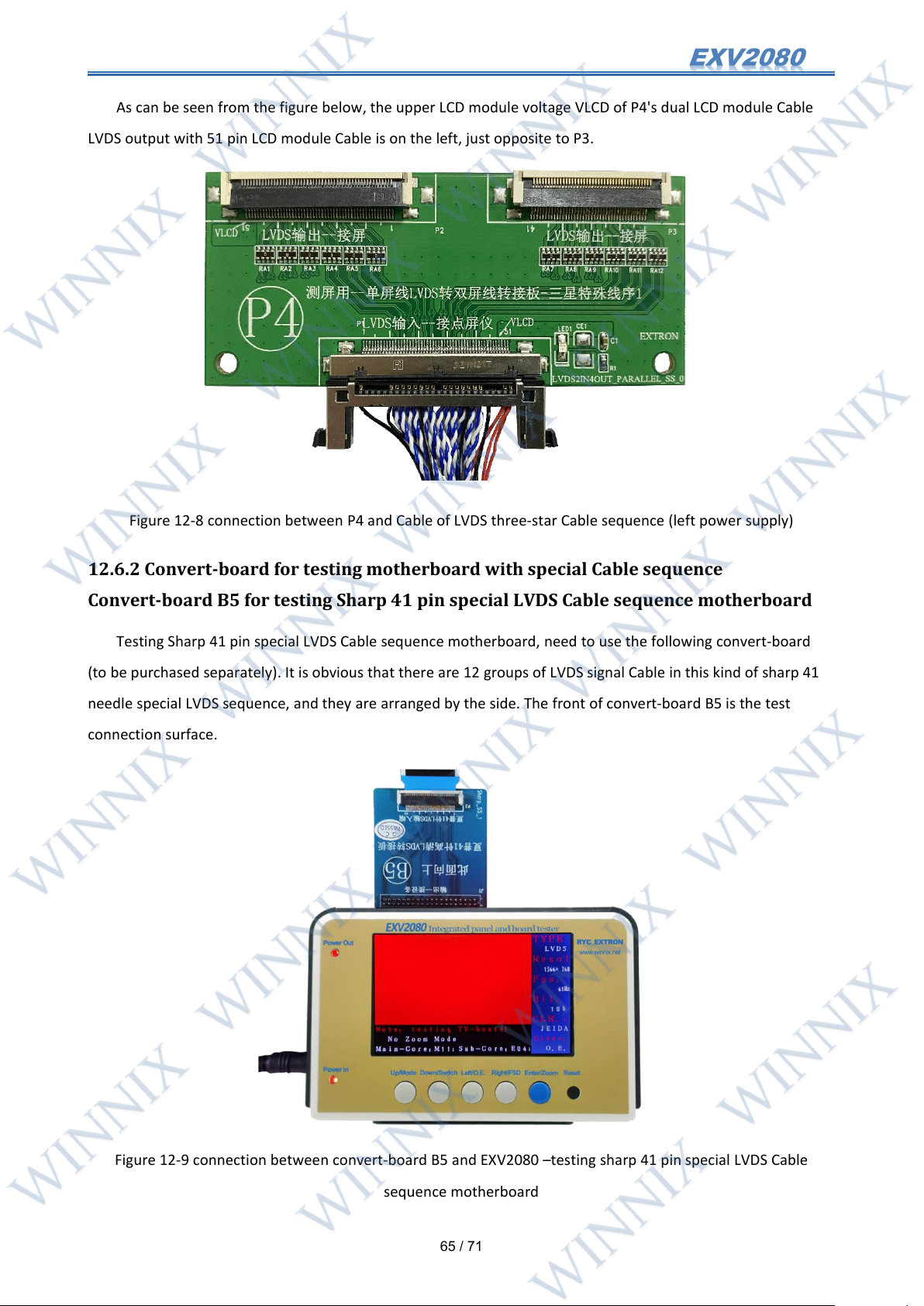
Convert-board P4 with Double Cable LVDS Samsung Cable sequence (left power supply)
The use of P4 (to be purchased separately) is the same as that of P3. When in use, the LCD module cable
connected to the LVDS interface of exv2080 is the LVDS cable labeled with white.
Figure 12-7 connection between P4 and EXV2080 of LVDS Samsung Cable sequence (left power supply)
Page 66
65
/ 71
As can be seen from the figure below, the upper LCD module voltage VLCD of P4's dual LCD module Cable
LVDS output with 51 pin LCD module Cable is on the left, just opposite to P3.
Figure 12-8 connection between P4 and Cable of LVDS three-star Cable sequence (left power supply)
12.6.2 Convert-board for testing motherboard with special Cable sequence
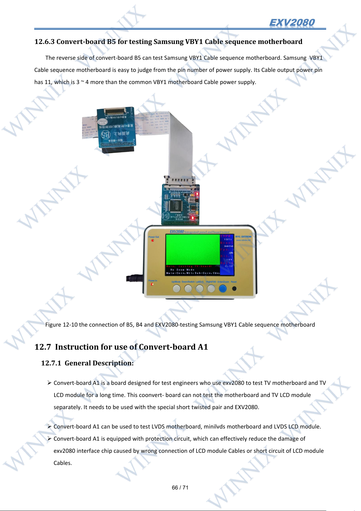
Convert-board B5 for testing Sharp 41 pin special LVDS Cable sequence motherboard
Testing Sharp 41 pin special LVDS Cable sequence motherboard, need to use the following convert-board
(to be purchased separately). It is obvious that there are 12 groups of LVDS signal Cable in this kind of sharp 41
needle special LVDS sequence, and they are arranged by the side. The front of convert-board B5 is the test
connection surface.
Figure 12-9 connection between convert-board B5 and EXV2080 –testing sharp 41 pin special LVDS Cable
sequence motherboard
Page 67
66
/ 71
12.6.3 Convert-board B5 for testing Samsung VBY1 Cable sequence motherboard
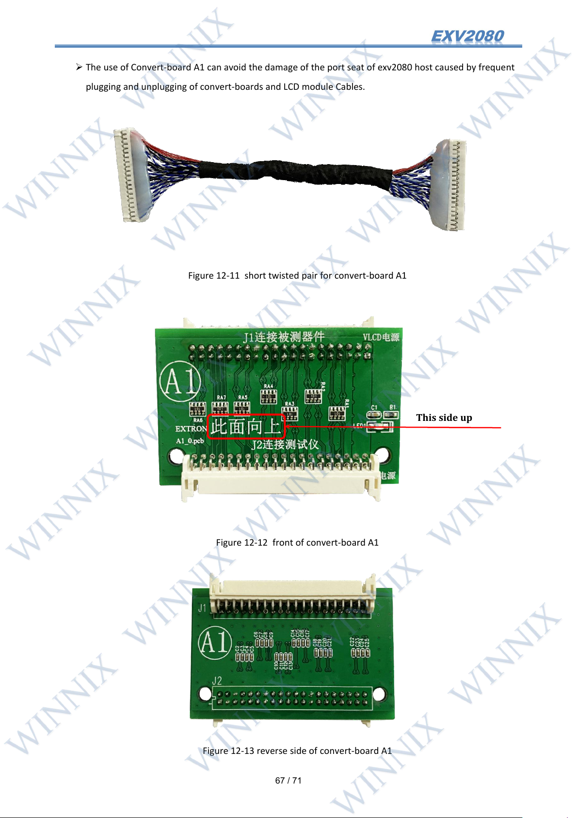
The reverse side of convert-board B5 can test Samsung VBY1 Cable sequence motherboard. Samsung VBY1
Cable sequence motherboard is easy to judge from the pin number of power supply. Its Cable output power pin
has 11, which is 3 ~ 4 more than the common VBY1 motherboard Cable power supply.
Figure 12-10 the connection of B5, B4 and EXV2080-testing Samsung VBY1 Cable sequence motherboard
12.7 Instruction for use of Convert-board A1
12.7.1 General Description:
Convert-board A1 is a board designed for test engineers who use exv2080 to test TV motherboard and TV
LCD module for a long time. This coonvert- board can not test the motherboard and TV LCD module
separately. It needs to be used with the special short twisted pair and EXV2080.
Convert-board A1 can be used to test LVDS motherboard, minilvds motherboard and LVDS LCD module.
Convert-board A1 is equipped with protection circuit, which can effectively reduce the damage of
exv2080 interface chip caused by wrong connection of LCD module Cables or short circuit of LCD module
Cables.
Page 68
67
/ 71
The use of Convert-board A1 can avoid the damage of the port seat of exv2080 host caused by frequent
This side up
plugging and unplugging of convert-boards and LCD module Cables.
Figure 12-11 short twisted pair for convert-board A1
Figure 12-12 front of convert-board A1
Figure 12-13 reverse side of convert-board A1
Page 69
68
/ 71
12.7.2 The method of connecting Convert-board A1
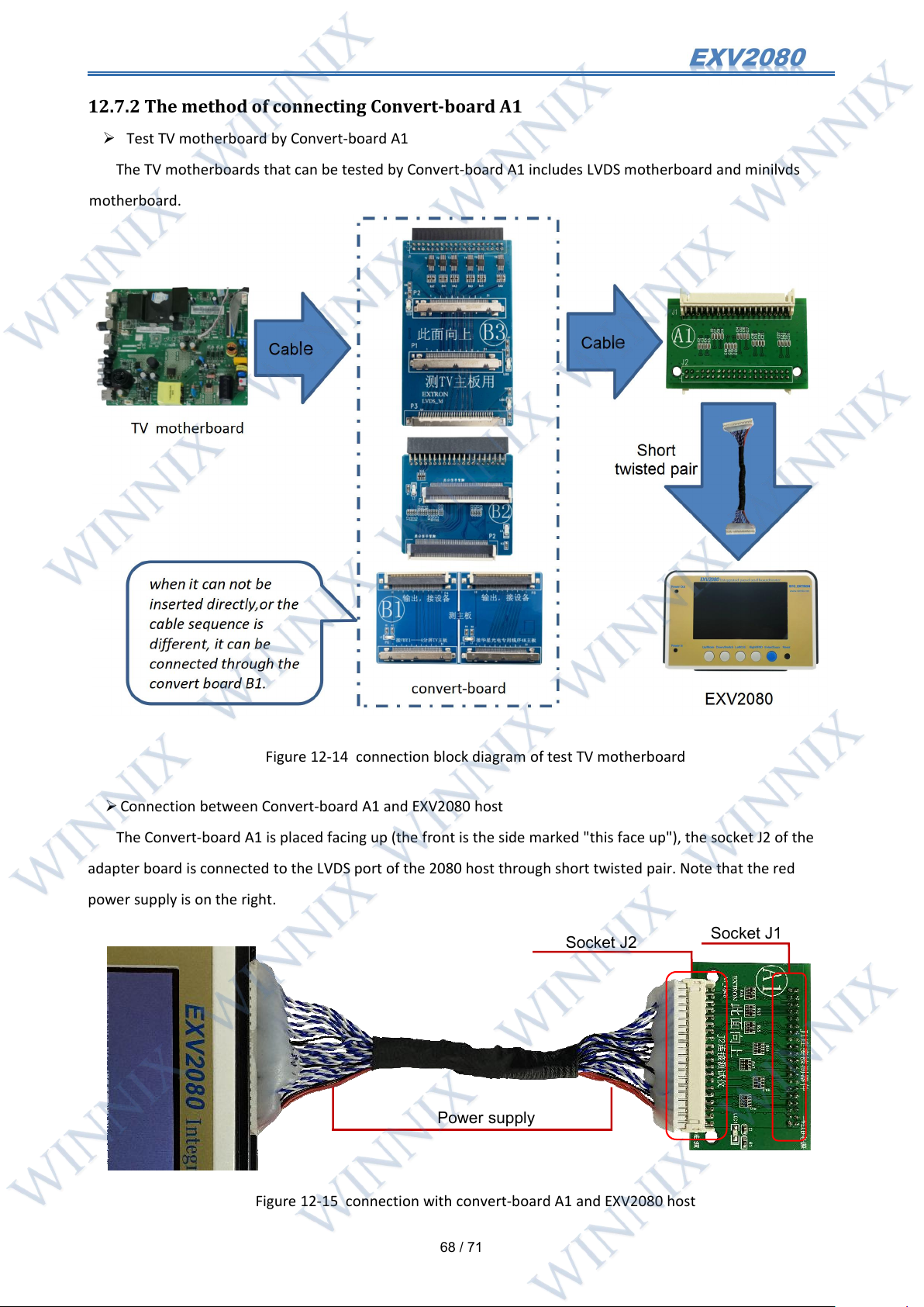
Power supply
Socket J1
Socket J2
Test TV motherboard by Convert-board A1
The TV motherboards that can be tested by Convert-board A1 includes LVDS motherboard and minilvds
motherboard.
Figure 12-14 connection block diagram of test TV motherboard
Connection between Convert-board A1 and EXV2080 host
The Convert-board A1 is placed facing up (the front is the side marked "this face up"), the socket J2 of the
adapter board is connected to the LVDS port of the 2080 host through short twisted pair. Note that the red
power supply is on the right.
Figure 12-15 connection with convert-board A1 and EXV2080 host
Page 70
69
/ 71
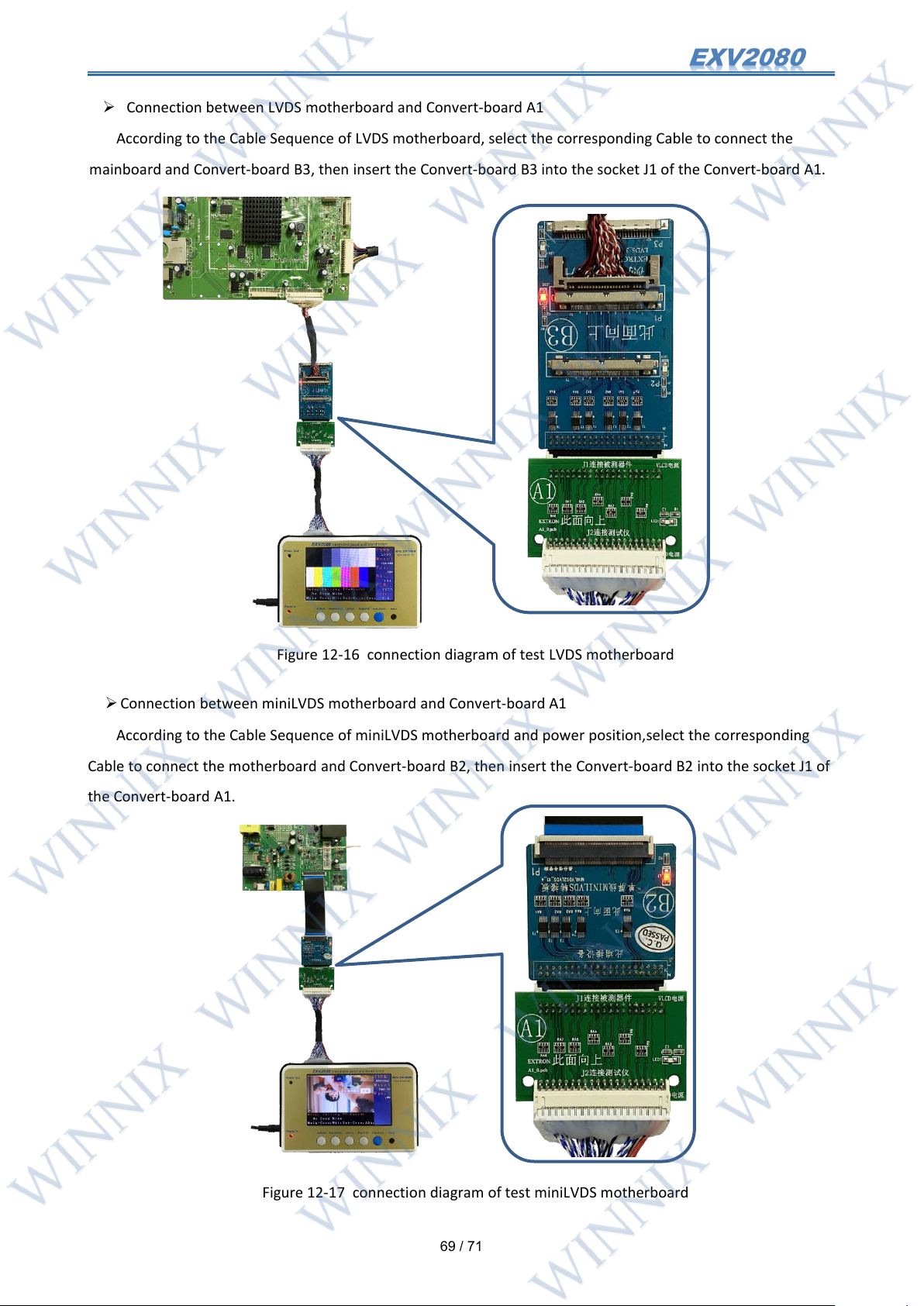
Connection between LVDS motherboard and Convert-board A1
According to the Cable Sequence of LVDS motherboard, select the corresponding Cable to connect the
mainboard and Convert-board B3, then insert the Convert-board B3 into the socket J1 of the Convert-board A1.
Figure 12-16 connection diagram of test LVDS motherboard
Connection between miniLVDS motherboard and Convert-board A1
According to the Cable Sequence of miniLVDS motherboard and power position,select the corresponding
Cable to connect the motherboard and Convert-board B2, then insert the Convert-board B2 into the socket J1 of
the Convert-board A1.
Figure 12-17 connection diagram of test miniLVDS motherboard
Page 71
70
/ 71
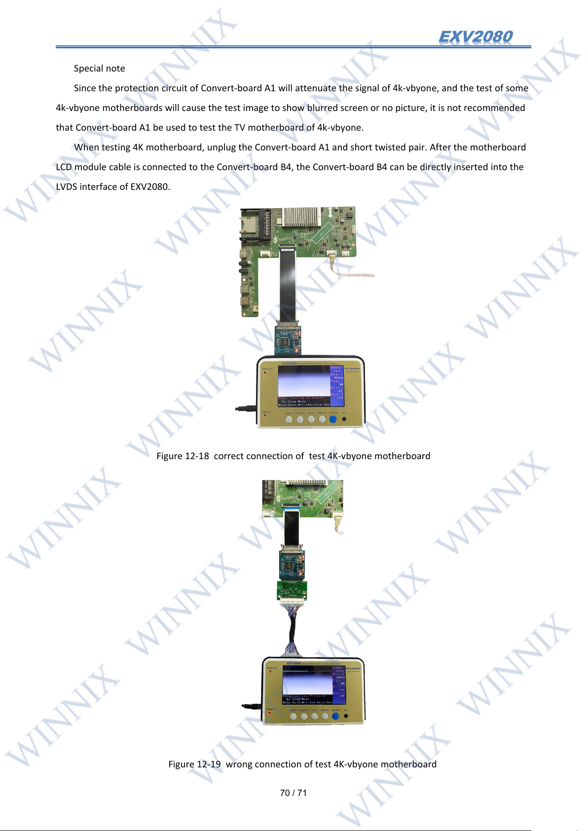
Special note
Since the protection circuit of Convert-board A1 will attenuate the signal of 4k-vbyone, and the test of some
4k-vbyone motherboards will cause the test image to show blurred screen or no picture, it is not recommended
that Convert-board A1 be used to test the TV motherboard of 4k-vbyone.
When testing 4K motherboard, unplug the Convert-board A1 and short twisted pair. After the motherboard
LCD module cable is connected to the Convert-board B4, the Convert-board B4 can be directly inserted into the
LVDS interface of EXV2080.
Figure 12-18 correct connection of test 4K-vbyone motherboard
Figure 12-19 wrong connection of test 4K-vbyone motherboard
Page 72
71
/ 71
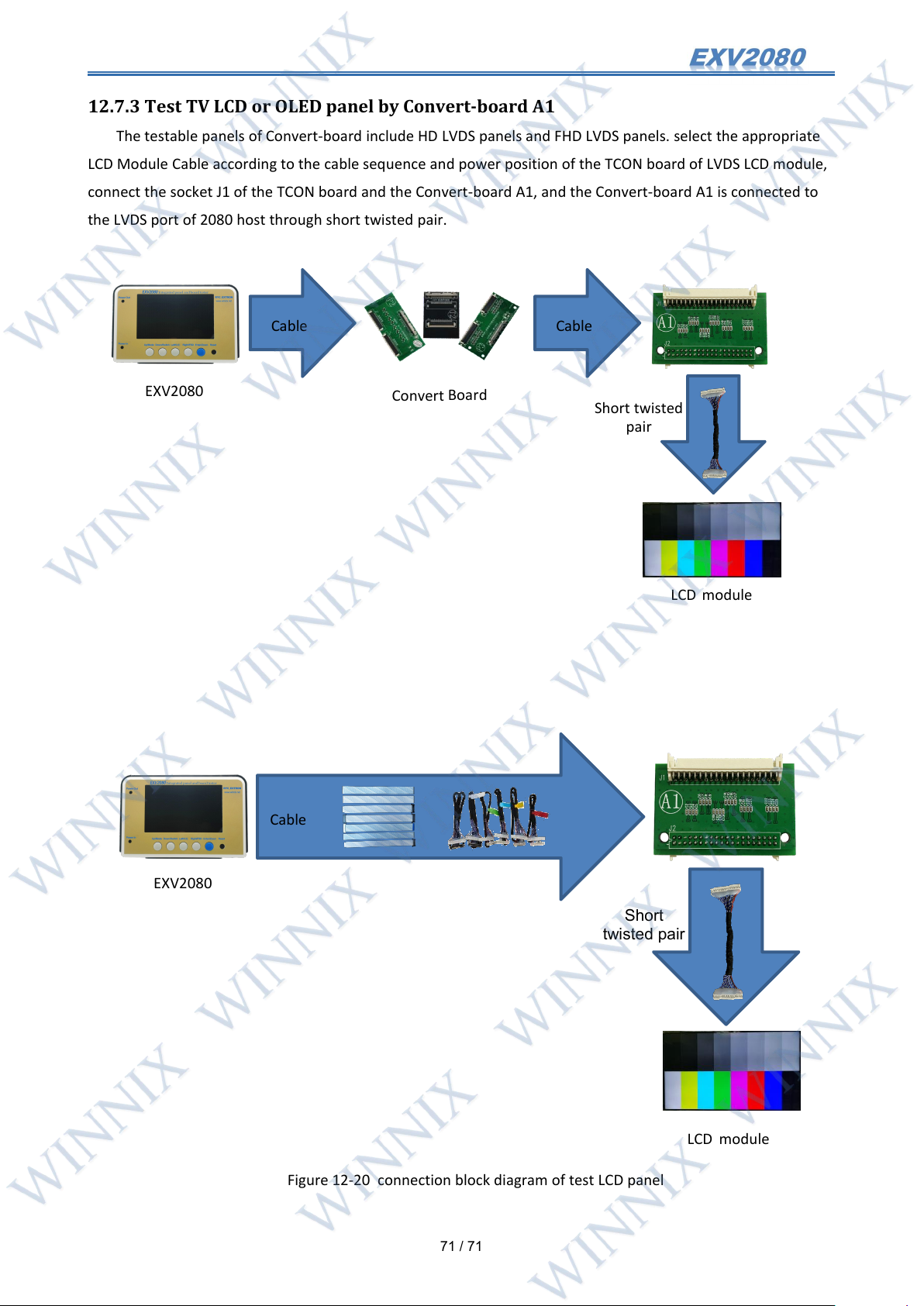
12.7.3 Test TV LCD or OLED panel by Convert-board A1
Cable
Cable
EXV2080
Convert
Board
LCD module
Short twisted
pair
Cable
EXV2080
LCD module
Short
twisted pair
The testable panels of Convert-board include HD LVDS panels and FHD LVDS panels. select the appropriate
LCD Module Cable according to the cable sequence and power position of the TCON board of LVDS LCD module,
connect the socket J1 of the TCON board and the Convert-board A1, and the Convert-board A1 is connected to
the LVDS port of 2080 host through short twisted pair.
Figure 12-20 connection block diagram of test LCD panel
 Loading...