

Page 1

TABLE OF CONTENTS
1 – INTRODUCTION
About this Manual ............................................................................................................................ 1-1
Safety Messages Used in this Manual .............................................................................................. 1-1
Pre-Delivery Inspection ....................................................................................................................1-2
Front Axle Tire Alignment ............................................................................................................... 1-2
Service and Assistance ...................................................................................................................... 1-2
Reporting Safety Defects .................................................................................................................. 1-2
Occupant and Cargo Carrying Capacity Label .................................................................................1-3
Vehicle Certification Label ............................................................................................................... 1-4
specifications and Capacities ............................................................................................................ 1-5
Owner and Vehicle Information ....................................................................................................... 1-6
2011 New Vehicle Limited Warranty ............................................................................................... 1-7
2 – SAFETY AND PRECAUTIONS
General Warnings ............................................................................................................................. 2-1
Driving Safety ................................................................................................................................... 2-1
Fuel and Propane Gas ....................................................................................................................... 2-1
LP Gas Leaks .................................................................................................................................... 2-2
Propane Gas Leak Detector .............................................................................................................. 2-2
Carbon Monoxide Warning .............................................................................................................. 2-3
Carbon Monoxide Alarm .................................................................................................................. 2-3
Smoke Alarm .................................................................................................................................... 2-4
Fire Extinguisher ............................................................................................................................... 2-4
Electrical ........................................................................................................................................... 2-5
Loading ............................................................................................................................................. 2-5
Maintenance ...................................................................................................................................... 2-5
Emergency Exits ............................................................................................................................... 2-5
Power Sofas and Beds ....................................................................................................................... 2-6
Slideout Rooms ................................................................................................................................. 2-6
Formaldehyde Information ............................................................................................................... 2-7
Mold, Moisture, and Your Motor Home ........................................................................................... 2-7
Roof and Ladders .............................................................................................................................. 2-8
Roadside Emergency ........................................................................................................................ 2-8
Jump Starting ....................................................................................................................................2-9
Engine Overheat ............................................................................................................................. 2-10
5 - DASH / AUTO
3 – DRIVING YOUR MOTOR HOME
Seats – Driver/Co-Pilot ..................................................................................................................... 3-1
Passenger Footrest ............................................................................................................................ 3-2
Seat Belts .......................................................................................................................................... 3-3
Child Restraints ................................................................................................................................. 3-4
KeyOne™ Lock System ................................................................................................................... 3-5
Mirrors – Power Electric ................................................................................................................... 3-5
Rev. 1119110425 Part No. 161500-11-016
Copyright 2010 Winnebago Industries, Inc. All rights reserved.
Page 2

Table Of Contents
12-Volt Front Drop-Down Solar/Night Shade .................................................................................. 3-6
Brake-Shift Interlock ........................................................................................................................ 3-7
Park Brake – Foot Pedal ................................................................................................................... 3-7
Fuel Pump Shut-Off Switch .............................................................................................................. 3-7
Tow/Haul Transmission Mode ......................................................................................................... 3-7
Hazard Warning Flashers .................................................................................................................. 3-7
Signal Lever/Headlight High-Low Beam .........................................................................................3-8
Map Light Switch ............................................................................................................................. 3-8
Battery Boost Switch ........................................................................................................................ 3-8
Air Conditioner/Heater – Automotive (Dash) .................................................................................. 3-9
Heater – Rear Coach (Automotive) .................................................................................................. 3-9
Defrost Fans ...................................................................................................................................... 3-9
Radio In-Dash/Rearview Monitor System ...................................................................................... 3-10
Sirius® Plug and Play Satellite Radio ............................................................................................ 3-11
CB Radio Power Wiring ................................................................................................................. 3-12
Front Service Access ...................................................................................................................... 3-12
Engine Access – Interior ................................................................................................................. 3-13
Engine Cooling System .................................................................................................................. 3-14
Chassis Battery Disconnect Switch ................................................................................................ 3-14
Tires ................................................................................................................................................ 3-14
Suspension Alignment and Tire Balance ........................................................................................ 3-15
Lights .............................................................................................................................................. 3-15
Circuit Breakers and Fuses – Chassis/Dash Automotive 12-Volt ..................................................3-15
4 – APPLIANCES AND SYSTEMS
Refrigerator ....................................................................................................................................... 4-1
Ice Maker ..........................................................................................................................................4-2
Refrigerator Service Access Compartment ....................................................................................... 4-2
Range and Oven ................................................................................................................................ 4-3
Microwave Oven/Range Hood ......................................................................................................... 4-4
OnePlace® Systems Monitor Panel .................................................................................................. 4-4
Solar Charger Panel .......................................................................................................................... 4-6
Power Control System (PCS) ........................................................................................................... 4-6
Water Heater - Gas/ Electric ............................................................................................................. 4-7
MotorAid Water Heater .................................................................................................................... 4-7
Pressure-Temperature Relief Valve .................................................................................................. 4-8
Electronic Thermostat ....................................................................................................................... 4-9
Electronic Thermostat Operation Chart ..........................................................................................4-12
Air Conditioner Filters .................................................................................................................... 4-12
Washer/Dryer .................................................................................................................................. 4-13
Washer/Dryer - Stackable ............................................................................................................... 4-14
Washer/Dryer - Prep Package ......................................................................................................... 4-15
5 – PROPANE GAS
Propane Gas Supply .......................................................................................................................... 5-1
Safe Use of the Propane Gas System ................................................................................................ 5-2
Propane Gas Warnings and Precautions ...........................................................................................5-3
Propane Gas Pressure Regulator ....................................................................................................... 5-4
Propane Vaporization in Cold Weather ............................................................................................ 5-5
Page 3

Table Of Contents
6 – ELECTRICAL
Electrical Cautions ............................................................................................................................ 6-1
Electrical System – House 120-Volt AC ..........................................................................................6-1
External Power Cord ......................................................................................................................... 6-1
Inverter Unit – 1000W ...................................................................................................................... 6-2
Power Center ..................................................................................................................................... 6-3
Circuit Breakers – House 120-Volt AC ............................................................................................ 6-4
Electrical Outlets – House 120-Volt AC .......................................................................................... 6-4
Ground Fault Circuit Interrupter ....................................................................................................... 6-5
Electrical Generator .......................................................................................................................... 6-5
Electrical System – House 12-Volt DC ............................................................................................ 6-7
House/Coach Battery Disconnect Switch ......................................................................................... 6-8
Battery Access .................................................................................................................................. 6-8
Battery Care ...................................................................................................................................... 6-9
Circuit Breakers – House 12-Volt .................................................................................................. 6-10
7 – PLUMBING
Fresh Water System .......................................................................................................................... 7-1
Utility Light ...................................................................................................................................... 7-2
Water Pump ...................................................................................................................................... 7-2
Ice Maker Water Filter ...................................................................................................................... 7-4
Filtered Water Faucet ........................................................................................................................ 7-5
Disinfecting Your Fresh Water System ............................................................................................ 7-5
Shower Hose Vacuum Breaker ......................................................................................................... 7-6
Exterior Shower/Wash Station .......................................................................................................... 7-6
Toilet ................................................................................................................................................. 7-7
Toilet - Electric Flush ....................................................................................................................... 7-7
Drainage System (P-Traps) ............................................................................................................... 7-8
Waste Water System ......................................................................................................................... 7-8
WaterLine & Tank Drain Valves .................................................................................................... 7-10
Water Heater Bypass Valve ............................................................................................................ 7-11
Winterizing Procedures ................................................................................................................... 7-11
Winterizing Optional Appliances ................................................................................................... 7-16
Water System Drain Valve Locations ............................................................................................ 7-19
8 – ENTERTAINMENT
High Definition Video Selection System .......................................................................................... 8-1
Front TV Ignition Switch Interlock .................................................................................................. 8-2
Audio-Video System Basic Operation .............................................................................................. 8-2
DVD Home Theater System ............................................................................................................. 8-2
CD/DVD Player - Bedroom .............................................................................................................. 8-3
CD/DVD Player ................................................................................................................................ 8-4
TV (Dining Buffet) - Power Lift ....................................................................................................... 8-5
Bedroom DVD Cables ...................................................................................................................... 8-6
TV Antenna ....................................................................................................................................... 8-6
TV Signal Amplifier ......................................................................................................................... 8-7
Satellite Dish and Cable TV Connections ........................................................................................8-7
TV Digital Satellite System Wiring .................................................................................................. 8-7
Page 4

Table Of Contents
TV Digital Satellite System – Manual ..............................................................................................8-8
TV Digital Satellite System (Automatic/In-Motion) ........................................................................ 8-8
Dish Network® Satellite Receiver .................................................................................................. 8-10
Exterior Entertainment Center ........................................................................................................ 8-11
9 – FURNITURE AND SOFTGOODS
Lounge Chair Base Clamp ................................................................................................................ 9-1
Buffet Table and Chairs .................................................................................................................... 9-1
Sleeping Facilities ............................................................................................................................. 9-3
Dinette/Bed Conversion .................................................................................................................... 9-3
U-Shaped Dinette/Bed Conversion ................................................................................................... 9-5
Sofa/Bed Conversion ........................................................................................................................ 9-6
Rest Easy® Multi-Position Lounge .................................................................................................. 9-7
Digital Sleep Air Bed ........................................................................................................................ 9-9
Bed - Power Lift ............................................................................................................................... 9-9
Roller Shades (Manual) - Solar Day/Night ..................................................................................... 9-10
Wood Furniture and Cabinetry ....................................................................................................... 9-10
10 – SLIDEOUT ROOMS AND LEVELING
Slideout Room Travel Locks - Electric .......................................................................................... 10-1
Slideout Room Travel Lock ............................................................................................................ 10-2
Slideout Room Retraction (with Rear Bedroom Sofa Option) ....................................................... 10-3
Slideout Room Retraction (with Power Lift Bed Option) .............................................................. 10-3
Slideout Room Operation – Electric ............................................................................................... 10-3
Slideout Room – Extreme Weather Precaution .............................................................................. 10-5
Slideout Room Troubleshooting – Electric .................................................................................... 10-6
Slideout Emergency Retraction - Electric .......................................................................................10-7
Slideout Emergency Retraction - Bedroom .................................................................................... 10-8
General Slideout Care ..................................................................................................................... 10-9
Leveling System ............................................................................................................................. 10-9
Checking Hydraulic Oil Level ...................................................................................................... 10-11
11 – MAINTENANCE AND STORAGE
Sealants – Inspection and General Information ..............................................................................11-1
Roof ................................................................................................................................................ 11-1
Undercarriage .................................................................................................................................. 11-1
Exterior Automotive Paint Finish ................................................................................................... 11-2
Care of Appliques and Decals ......................................................................................................... 11-4
Front End Masks and Paint Damage ............................................................................................... 11-4
Plastic Parts – Cleaning .................................................................................................................. 11-4
Headlights and Exterior Lights ....................................................................................................... 11-5
Interior Soft Goods ......................................................................................................................... 11-6
Cabinetry – Cleaning ...................................................................................................................... 11-7
Solid Surface Countertop – Corian® .............................................................................................. 11-7
Stainless Steel Appliances .............................................................................................................. 11-8
Galley Sink ..................................................................................................................................... 11-8
Range and Refrigerator ................................................................................................................... 11-9
Bathroom ........................................................................................................................................ 11-9
Doors and Windows ........................................................................................................................ 11-9
Page 5

Table Of Contents
Vehicle Storage – Preparation ...................................................................................................... 11-10
Vehicle Storage – Removal .......................................................................................................... 11-10
Chassis Service and Maintenance ................................................................................................. 11-11
Chassis Fuses and Relays ............................................................................................................. 11-11
Coach Maintenance Chart ............................................................................................................. 11-13
12 – MISCELLANEOUS
Loading the Vehicle ........................................................................................................................ 12-1
Weighing Your Loaded Vehicle ..................................................................................................... 12-1
Car or Trailer Towing ..................................................................................................................... 12-3
Trailer Wiring Connector ................................................................................................................ 12-4
Towing Guidelines .......................................................................................................................... 12-4
Entry Step – Electric ....................................................................................................................... 12-5
Tool and Ladder Storage ................................................................................................................. 12-6
Roof Ladder .................................................................................................................................... 12-7
Storage Compartment Doors .......................................................................................................... 12-7
Compartment Lights Switch ........................................................................................................... 12-7
Power Awning ................................................................................................................................ 12-8
Windows ......................................................................................................................................... 12-9
Power Roof Ventilator .................................................................................................................. 12-10
Effects of Prolonged Occupancy .................................................................................................. 12-10
Page 6

Page 7

SECTION 1 – INTRODUCTION
Congratulations! We welcome you to the
exciting world of motor home travel and
camping. You will find it convenient and
enjoyable to have all the comforts of home and
still enjoy the great outdoors wherever you
choose to go. Your motor home has been
carefully designed, engineered, and
manufactured to provide years of enjoyment.
Before sliding into the driver’s seat, please
become familiar with operations and features. In
addition, spend some time with the dealer when
you take delivery to learn all you can about your
new motor home.
ABOUT THIS MANUAL
This operator’s manual was prepared to aid
you in the proper care and operation of the
vehicle and equipment.
Please read this manual completely to
understand how everything in your coach works
before taking it on its “maiden voyage”.
NOTE: This manual describes many features of
your motor home and includes
instructions for its safe use.
This manual, including photographs and
illustrations, is of a general nature only.
Some equipment and features described
or shown in this manual may be
optional or unavailable on your model.
Because of Winnebago Industries
continuous program of product
improvement, it is possible that recent
product changes and information may
not be included.
The instructions included in this manual
are intended as a guide, and in no way
extend the responsibilities of Winnebago
Industries beyond the standard written
warranty as presented in this manual.
The descriptions, illustrations, and
specifications in this manual were
correct at the time of printing. We reserve
the right to change specifications or
®
’
design without notice, and without
incurring obligation to install the same
on products previously manufactured.
The materials in your InfoCase contain
warranty information and operating and
maintenance instructions for the various
appliances and components in your motor home.
NOTE: Many of the instruction sheets and
manuals for the various appliances and
components have been incorporated into
the Operator’s Manual Supplement for
your convenience.
Please read the FAQ in Section 1 of the
Operator’s Manual Supplement for more
details.
Throughout this manual, frequent reference is
made to the vehicle chassis manual that is
provided by the manufacturer of the chassis on
which this motor home is built.
Consult the chassis manual for operating,
safety, and maintenance instructions pertaining
to the chassis section of the motor home.
SAFETY MESSAGES USED IN THIS MANUAL
Throughout this manual, certain items are
labeled Danger, Warning, Caution, or Note.
These terms alert you to precautions that may
involve damage to your vehicle or a risk to your
personal safety. Read and follow them carefully.
DA NG E R
DANGER indicates a hazardous situation
which, if not avoided, will result in death or
serious personal injury.
5 - DASH / AUTO
1-1
Page 8

SECTION 1 –
INTRODUCTION
WARNING
WARNING indicates a hazardous
situation which, if not avoided, could
result in death or serious personal injury.
CAUTION
CAUTION indicates a hazardous
situation which, if not avoided, could
result in minor or moderate personal
injury.
NOTICE
NOTICE is used to address practices not
related to personal injury.
NOTE: A “Note” is not necessarily safety-
related, but indicates a recommendation
or special point of information that could
assist in understanding the use or care of
a feature item.
FRONT AXLE TIRE ALIGNMENT
We recommend that you have the front
suspension and steering alignment checked and
adjusted after you have fully loaded the vehicle
according to your needs. Thereafter, have
alignment inspected periodically to maintain
vehicle steering performance and prevent uneven
tire wear.
SERVICE AND ASSISTANCE
Your dealer will be glad to provide any
additional information you need, as well as
answer any questions you might have about
operating the equipment in your coach. When it
comes to service, remember that your dealer
knows your vehicle best and is interested in your
satisfaction. Your dealer will provide quality
maintenance and any other assistance that you
may require during your ownership of this
vehicle.
If you need warranty repairs while traveling,
you may take your vehicle to any authorized
Winnebago Industries® dealership and request
their assistance.
See the Service Dealer Directory in your
InfoCase.
PRE-DELIVERY INSPECTION
This motor home has been thoroughly
inspected before shipment. Your dealer is
responsible for performing a complete predelivery inspection of the chassis and all motor
home components.
As a part of the pre-delivery inspection
procedure, the dealer is responsible for road
testing the motor home, noting, and correcting
any problems before delivery.
1-2
REPORTING SAFETY DEFECTS
If you believe that your vehicle has a defect
which could cause a crash or could cause injury
or death, you should immediately inform the
National Highway Traffic Safety Administration
(NHTSA) in addition to notifying Winnebago
Industries, Inc.
If NHTSA receives similar complaints, it may
open an investigation, and if it finds that a safety
defect exists in a group of vehicles, it may order
a recall and remedy campaign. However,
NHTSA cannot become involved in individual
problems between you, your dealer, or
Winnebago Industries®.
To contact NHTSA, you may either call the
Vehicle Safety Hotline toll-free at:
1-888-327-4236; (TTY: 1-800-424-9153)
Page 9
or go to their website at http://www.safercar.gov
or write to:
Administrator, NHTSA
1200 New Jersey Avenue S.E.
Washington, D.C. 20590
You can also obtain other information about
motor vehicle safety from the NHTSA website
at http://www.safercar.gov
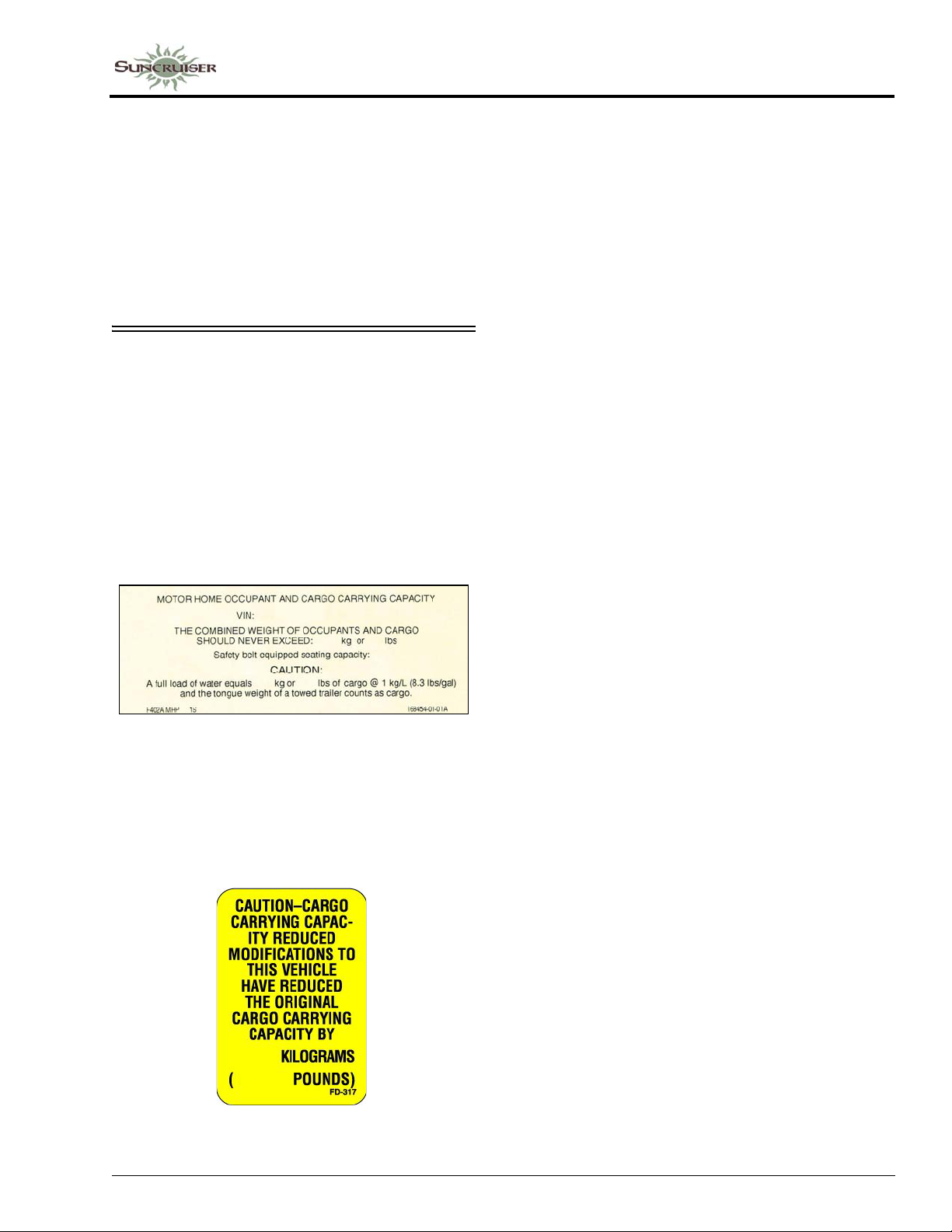
OCCUPANT AND CARGO CARRYING CAPACITY LABEL
This label is affixed in the driver’s area next to
or near the Vehicle Certification Label. It
contains vehicle occupant and cargo carrying
capacity along with the number of seat belt
positions in the vehicle. The label also provides
the weight of a full load of water and advises that
this weight, along with the tongue weight counts
as cargo.
SECTION 1 –
INTRODUCTION
If any weight exceeding 45.4 kg (100 lbs.) is
added to your coach between final vehicle
certification and first retail sale, the occupant and
cargo carrying capacity must be corrected and a
label similar to the one shown below will be
affixed inside your coach.
1-3
Page 10
SECTION 1 –
INTRODUCTION
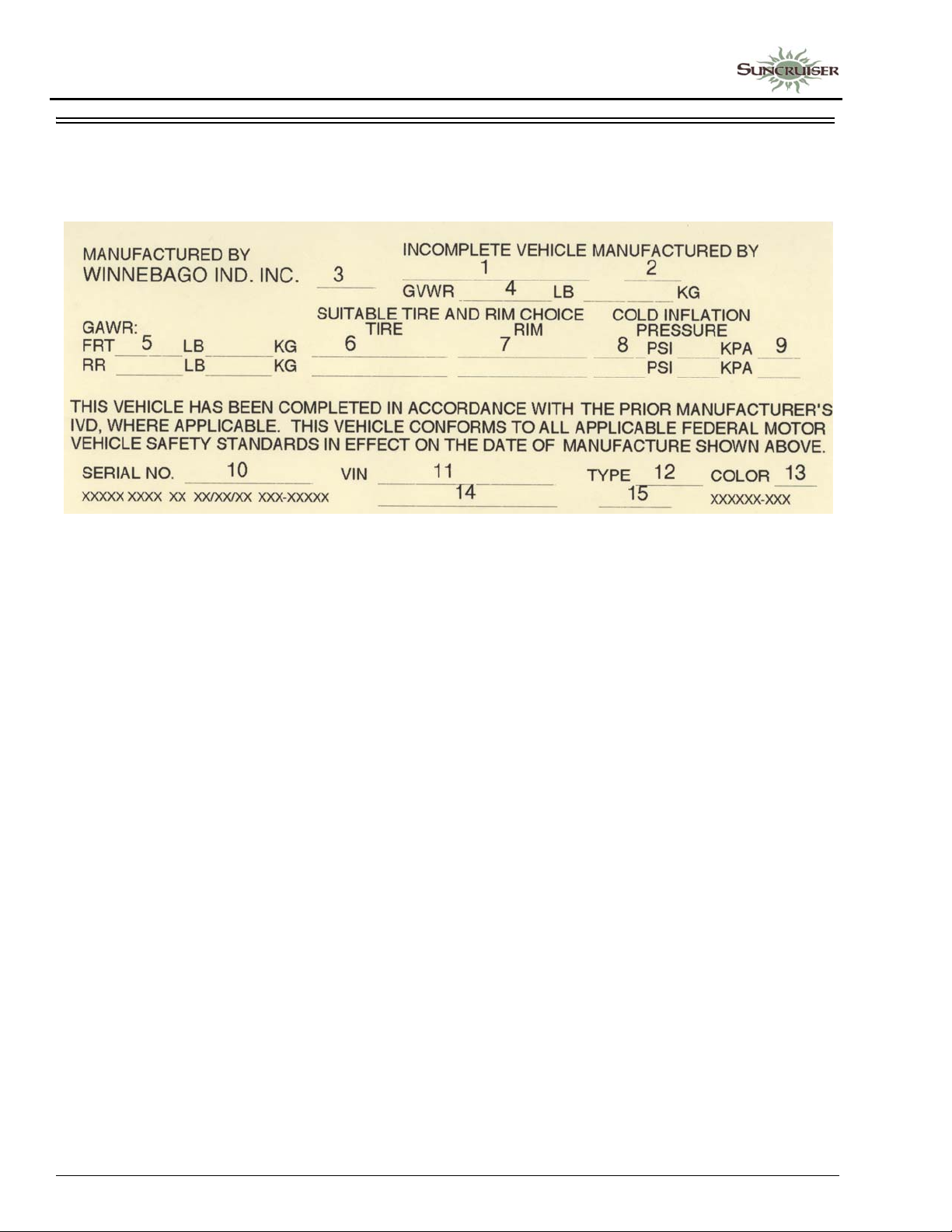
VEHICLE CERTIFICATION LABEL
This label is affixed to the lower driver side armrest panel, driver door, or the driver side door jamb,
depending on model. It contains vehicle identification numbers and other important reference information.
EXPLANATION OF DATA
1. Chassis manufacturer.
2. Chassis manufacture date.
3. Month and year of manufacture at Winnebago Industries®.
4. Gross Vehicle Weight Rating: Total permissible weight of the vehicle, including driver, passengers, total cargo carried (including all liquids), and equipped with all options.
5. Gross Axle W eight Rating: Total permissible weight allowed for the front and rear axles (listed in pounds and kilograms).
6. Suitable Tire Choice: Tires recommended to meet handling and safety requirements. When replacing any of the tires on your vehicle, always replace with a tire that meets these specifications.
7. Suitable Rim Choice: Wheel rims recommended to meet handling and safety requirements. When replacing any of the rims on your vehicle, always replace with a rim that meets these specifications.
8. Cold Inflation Pressure: Inflation pressures at
Gross Axle Weight Ratings recommended
(while cold) for the tires originally equipped
on your vehicle. These pressure levels must be
maintained to assure proper handling, safety,
and fuel economy.
9. Rear Axle Wheel Configuration: Single or Dual as it relates to the inflation.
10. Serial Number: This is the serial number assigned to the completed vehicle by Winnebago Industries.
11. Vehicle Identification Number (VIN): This
number identifies the chassis on which the
motor home is built. The 10th digit of the VIN
designates the chassis model year. (7=2007,
8=2008, etc.). This information is useful when
ordering chassis repair parts.
12. Type: States the NHTSA designated usage classification for your motor home. MPV signifies a Multi-purpose Passenger Vehicle.
13. Color: Signifies the color code number of the decor used throughout the vehicle. This number is necessary for ordering replacement cushions, curtains, carpet, etc.
®
14. Winnebago
name.
15. Model: Lists the Winnebago product model number of your vehicle.
model year and series/family
1-4
Page 11
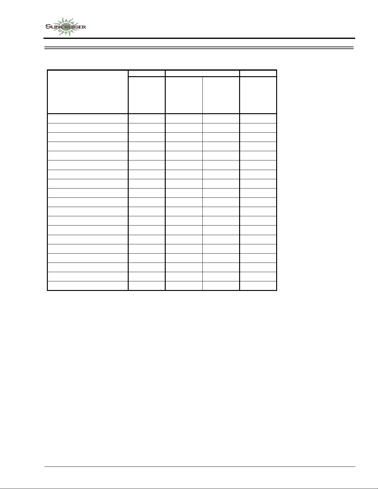
SPECIFICATIONS AND CAPACITIES
SECTION 1 –
INTRODUCTION
Itasca Suncruiser
32H 37F
®
F53
Ford
22,000 lb.
Chassis with
22.5" Tires
Standard
Ford
22,000 lb.
Chassis with
22.5" Tires
®
F53
35P
Optional
Ford
24,000 lb.
Chassis with
22.5" Tires
®
F53
®
F53
Ford
24,000 lb.
Chassis with
22.5" Tires
Feature Number 16L 16L 16Z 16Z
Length 32' 9.5" 35' 4" 35' 4" 37' 3.4"
Exterior Height
Exterior Width
Exterior Storage
1
2
3
12' 9" 12' 8" 12' 8" 12' 7"
8' 5.5" 8' 5.5" 8' 5.5" 8' 5.5"
107.0 cu. ft. 105.1 cu. ft. 105.1 cu. ft. 116.0 cu. ft.
Awning Length 17' 17' 17' 18'
Interior Height 7' 7' 7' 7'
Interior Width 8' 0.5" 8' 0.5" 8' 0.5" 8' 0.5"
Freshwater Capacity
4
75 gal. 75 gal. 75 gal. 75 gal.
Water Heater Capacity 10 gal. 10 gal. 10 gal. 10 gal.
Holding Tank Capacity - Black
Holding Tank Capacity - Gray
Propane Capacity
5
4
4
43 gal. 43 gal. 43 gal. 52 gal.
48 gal. 60 gal. 60 gal. 71 gal.
23 gal. 28 gal. 28 gal. 28 gal.
Wheelbase 220" 228 228 248
GVWR 22,000 lbs. 22,000 lbs. 24,000 lbs. 24,000 lbs.
GAWR - Front 8,000 lbs. 8,000 lbs. 9,000 lbs. 9,000 lbs.
GAWR - Rear 15,000 lbs. 15,000 lbs. 15,500 lbs. 15,500 lbs.
GCWR
6
26,000 lbs. 26,000 lbs. 30,000 lbs. 30,000 lbs.
Fuel Capacity 80 gal. 80 gal. 80 gal. 80 gal.
Notes:
All measurements are based upon the most recent data available. See your dealer for specifications.
1
The height of each model is measured to the top of the tallest standard feature and is based on the curb weight of a typically
equipped unit. The actual height of your vehicle may vary by several inches depending on chassis or equipment variations.
Contact your dealer for further information.
2
Floorplans feature a wide-body design - over 96". You should be aware that some states restrict access on some or all state
roads to 96" in body width. You should confirm the road usage laws in the states of interest to you.
3
The load capacity of your motor home is designated by weight, not by volume, so you cannot necessarily use all available space
when loading your motor home.
4
Capacities are based on measurements prior to tank installation. Slight capacity variations can result upon installation.
5
Capacities shown are the tank manufacturer's listed water capacity (W.C.). Actual filled propane capacity is 80% of listing due
to overfilling prevention device on tank.
6
Actual towing capacity is dependent on your particular loading and towing circumstances which includes the GVWR, GAWR,
and GCWR as well as adequate trailer brakes. Refer to the chassis operator's manual of your motor home for further towing
information.
1-5
Page 12

SECTION 1 –
INTRODUCTION
OWNER AND VEHICLE INFORMATION
OWNER INFO
Owner’s Name(s) __________________________________________________________________
Address __________________________________________________________________________
__________________________________________________________________________
VEHICLE INFORMATION
Motor Home Model Number _________________________________________________________
Motor Home Serial Number __________________________________________________________
Chassis Vehicle Identification No. (VIN)________________________________________________
Vehicle Mileage at Delivery __________________________________________________________
Selling Dealer Name________________________________________________________________
Address __________________________________________________________________________
__________________________________________________________________________
YOUR WINNEBAGO INDUSTRIES® DEALER /SERVICE CENTER
Name____________________________________________________________________________
Address __________________________________________________________________________
__________________________________________________________________________
Contact ____________________________________________Phone ________________________
CHASSIS SERVICE CENTER
Name____________________________________________________________________________
Address __________________________________________________________________________
__________________________________________________________________________
Contact ____________________________________________Phone ________________________
RV INSURANCE POLICY
Company_________________________________________________________________________
Policy Number ____________________________________________________________________
Agent______________________________________________Phone ________________________
1-6
Page 13
2011 NEW VEHICLE LIMITED WARRANTY
WINNEBAGO INDUSTRIES, INC.
SECTION 1 –
INTRODUCTION
WARRANTY COVERAGE TO OWNER
Winnebago Industries, Inc. of Forest City, Iowa, warrants each new
Winnebago and Itasca motor home to the owner for recreational use
in the U.S.A. and Canada as follows:
BASIC LIMITED WARRANTY
WINNEBAGO INDUSTRIES’ RESPONSIBILITY
Any part of the vehicle subject to this warranty that is found to be
defective in material or workmanship under normal use and
maintenance will be repaired or replaced at Winnebago Industries’
option without charge to the customer for parts or labor upon notice
of the defect.
WARRANTY PERIOD
The basic Warranty Period is 12 months or 15,000 miles (24,135
kilometers), on the odometer, whichever occurs first. The Warranty
Period for all coverages begins on the date the vehicle is delivered to
the first retail purchaser or first placed in service as a demonstrator
or company vehicle.
ONLY WARRANTY
This limited warranty is the only warranty made or authorized by
Winnebago Industries. Winnebago Industries makes no other
promises, representations or warranties concerning the vehicle or
other matters set forth herein. Winnebago Industries does not
authorize any person to create for it any other obligations or liability
in connection with this vehicle.
DEALER’S REPRESENTATIONS EXCLUDED
Winnebago Industries shall not be bound by any undertaking,
representation, or warranty made by any dealers selling its product
to any purchaser of its products.
EXCLUSIVE REMEDY
THE PERFORMANCE OF REPAIRS IS THE EXCLUSIVE REMEDY
UNDER THIS LIMITED WARRANTY OR ANY IMPLIED
WARRANTY. ANY IMPLIED WARRANTY OF MERCHANTABILITY
OR FITNESS FOR A PARTICULAR PURPOSE APPLICABLE TO
THIS VEHICLE ARISING BY WAY OF STATE LAW IS LIMITED IN
DURATION TO THE DURATION OF THIS WRITTEN WARRANTY
AS HEREINBEFORE OR HEREINAFTER PROVIDED.
LIMITATION ON LIABILITY
WINNEBAGO INDUSTRIES SHALL NOT BE LIABLE FOR
INCIDENTAL OR CONSEQUENTIAL DAMAGES RESULTING
FROM BREACH OF THIS WRITTEN WARRANTY OR ANY
IMPLIED WARRANTY. SUCH DAMAGES INCLUDE, BUT ARE
NOT LIMITED TO, LOSS OF TIME, INCONVENIENCE, OR OTHER
CONSEQUENTIAL DAMAGE INCLUDING EXPENSE FOR
GASOLINE, TELEPHONE, TRAVEL, LODGING, LOSS OR
DAMAGE TO PERSONAL PROPERTY, OR LOSS OF REVENUE.
Some states do not allow limitations on how long an implied warranty
will last or the exclusion or limitation of incidental or consequential
damages, so the above limitations or exclusions may not apply to
you.
ITEMS NOT SUBJECT TO WARRANTY COVERAGE
Chassis, drivetrain and related components*
Wheels*
Tires*
Any other part or component covered by a written warranty issued by
its manufacturer*
Service Items, such as Windshield Wiper Blades, Lubricants, Fluids
& Filters
Adjustments
Rust and Corrosion
*These items are covered under the manufacturer’s individual
warranty.
ADDITIONAL EQUIPMENT NOT COVERED
Winnebago Industries cannot and does not accept any responsibility
in connection with any of its motor homes for additional equipment or
accessories installed at any dealership or other place of business, or
by any other party other than Winnebago Industries. Such installation
of equipment or accessories by any other party will not be covered
by the terms of this warranty.
36 MONTH/36,000 MILE STRUCTURAL WARRANTY
At the expiration of the Basic Coverage and for the remainder of the
period of 36 months or 36,000 miles (57,924 kilometers), on the
odometer, whichever occurs first, Winnebago Industries warrants the
following:
1. Structural defects of the subfloor, floor, and slide-out room.
Floor lamination failure and lamination failure of the subfloor
panels and risers are covered by the structural warranty.
2. Body Thermo-Panel
against delamination. Body Thermo-Panel
bonding of the exterior skin and the interior paneling to an
insulating core material. Delamination (separation of layers)
caused by other factors such as physical damage or failed
sealants is not covered by this warranty.
This warranty gives you specific legal rights and you may also have
other rights which vary from state to state.
Also, this warranty shall not apply to failures, damage or
malfunctions resulting from normal wear, misuse, abuse, negligence,
alteration, accident, fire, improper repair of the vehicle or failure to
follow recommended maintenance requirements.
OWNER’S RESPONSIBILITY-CARE AND MAINTENANCE
It is the owner’s responsibility to perform the care, maintenance and
proper load distribution described in the operator’s manual which
accompanies your motor home. Any damage which results to your
vehicle as a result of your failure to perform such duties, is not
covered.
Damage to appearance items such as fiberglass, metal, paint,
fabrics and trim, may occur during manufacturing or transporting.
Normally, any factory defect or damage is corrected at the factory. In
addition, dealers are obligated to inspect each vehicle upon delivery
to them and prior to delivery to you. You should also immediately
inspect appearance items and advise your selling dealer of any
discrepancies. Damage and deterioration due to use and exposure,
such as rust or corrosion is not covered by this warranty.
®
Lamination of the sidewalls and backwall
®
Lamination is the
1-7
Page 14

SECTION 1 –
INTRODUCTION
OBTAINING WARRANTY REPAIRS
While any Winnebago Industries motor home dealer can perform
warranty service, we recommend you return to the dealership that
sold you your vehicle. If you are touring or have moved, contact any
Winnebago Industries motor home dealer in the United States or
Canada for warranty service.
If a part of the system covered by this limited warranty fails to
function or requires service during the warranty period:
1. Promptly take the vehicle to the selling dealer for repair or
inspection.
2. Written notice of defects must be given to the selling dealer and
manufacturer.
3. If the dealer is incapable of making the repairs, request that he
contact Winnebago Industries, Inc.
4. If, after the above steps are completed and the repair is not
made, the customer should contact Winnebago Industries, Inc.,
605 West Crystal Lake Road, P.O. Box 152, Forest City, Iowa
50436, Attention: Owner Relations Department (800-537-1885)
and furnish the following information:
− The complete serial number of the vehicle
− Date of retail purchase
− Selling dealer’s name
− Nature of the service problem, and a brief explanation of
the steps or service the dealer has performed, and the
results obtained. The customer may be directed to another
dealer or service center for repairs to be completed, if such
a dealer or service center is better able to complete the
repair.
Winnebago Industries may, at its option, request the vehicle be
returned to Forest City, Iowa for repair. If the customer refuses to
allow repairs to be performed at the Forest City, Iowa facility, the
warranty on that repair will be voided.
5. If after the above steps are completed and the repairs are not
satisfactory, the customer may contact the Service
Administration Manager of Winnebago Industries, and request a
customer relations board meeting to resolve the problem. This
action, however, is not mandatory.
6. Certain components are covered by warranties provided by
individual component manufacturers. Please refer to the
component’s information supplied in the vehicle’s InfoCase.
COMMENCEMENT OF ACTIONS
CALIFORNIA
Winnebago Industries participates in the Consumer Arbitration
Program for Recreation Vehicles (CAP-RV). This third-party dispute
resolution program is available, at no charge to you, to settle
unresolved warranty disputes for recreational vehicles. This dispute
resolution program reviews eligible product and service related
complaints involving warranty covered components.
To find out more about the program, or to request an
application/brochure, please call the Arbitration Administration office
toll-free 800-279-5343.
The CAP-RV program operates as a certified mechanism under the
review of the California Arbitration Certification Program. You must
utilize the arbitration program before claiming rights conferred by 15
USC section 2310 (Uniform Commercial Code) or Civil Code section
1793.22(b) (Tanner Consumer Protection Act). You are not required
to use the program if you choose to seek redress by pursuing rights
and remedies not created by those laws.
Members of the Armed Forces who purchased the vehicle in
California, or who were stationed in or a resident of California at the
time of purchase (regardless of state of purchase) or who are
stationed in California at the time of application to this program, may
utilize the CAP-RV program.
:
Any action for breach of The Basic Limited or Structural Warranty or
any implied warranty shall be commenced within one-year after
expiration of the warranty.
CHANGES IN DESIGN
Winnebago Industries, Inc. reserves the right to make changes in
design and changes or improvements upon its products without
imposing any obligation upon itself to install the same upon its
products theretofore manufactured.
NEW YORK
If your motor home has been repaired three or more times for the
same nonconformity, defect, or condition, or if your motor home has
been out of service by reason of repair for twenty-one days, Section
198-a of the General Business Law of the State of New York
requires you to provide written notice by certified mail, return receipt
requested, to Winnebago Industries or its authorized dealer before
making any claim under that section of the law. If you do have
problems with your motor home, you should provide written notice to
Winnebago Industries at the following address:
:
Winnebago Industries, Inc.
605 West Crystal Lake Road
P.O. Box 152
Forest City, Iowa 50436
Attn: Owner Relations
10/09
1-8
Page 15

SECTION 2 – SAFETY AND PRECAUTIONS
GENERAL WARNINGS
• Only seats equipped with seat belts are to be
occupied while the vehicle is moving.
• Make sure all passengers have seat belts
fastened. Lap belts should fit low on the hips
and upper thighs. The shoulder belt should be
positioned snug over the shoulder.
• For pregnant women, the lap belt should be
placed under the abdomen and across the
upper thighs. The shoulder belt should be
positioned across the center of the chest.
Consult your doctor if you have any
questions.
• Child restraints should be installed properly
according to manufacturer’s instructions. See
“Child Restraints”.
• All moveable or swiveling seats should be
placed and locked in position while the
vehicle is moving.
• Never let passengers stand or kneel on seats
while the vehicle is moving.
• Sleeping facilities are not to be utilized while
vehicle is moving.
• Examine the escape window and be familiar
with its operation.
• Inspect the fire extinguisher monthly for
proper charge and operating condition. This
should also be done before beginning a
vacation or any extended trip.
• Use care when accelerating or decelerating on
a slippery surface. Abrupt speed changes can
cause skidding and loss of control.
• Never drive the vehicle with a slideout room
extended.
• Driving through water deep enough to wet the
brakes may affect stopping distance or cause
the vehicle to pull to one side. Check brake
operation in a safe area to be sure they have
not been affected. Never operate any vehicle if
a difference in braking efficiency is
noticeable.
• Adverse weather conditions and extremes in
terrain may affect handling and/or
performance of your vehicle. Refer to your
chassis manual for related information.
FUEL AND PROPANE GAS
DANGER
All pilot lights, appliances, and their
ignitors (see operating instructions)
shall be turned off before refueling of
motor fuel tanks and/or propane
containers. Failure to comply could
result in death or serious injury.
5 - DASH / AUTO
DRIVING SAFETY
• Do not attempt to adjust the driver’s seat while
the vehicle is moving.
• Do not adjust tilt steering in a moving vehicle.
• Do not operate the cruise control on icy or
extremely wet roads, winding roads, in heavy
traffic, or in any other traffic situation where
a constant speed cannot be maintained.
WARNING
Propane gas containers, gasoline, or
other flammable liquids shall not be
placed or stored onboard the vehicle
because a fire or explosion may result.
Propane gas containers are equipped
with safety valves, which relieve
excessive pressure by discharging gas
to the atmosphere. Failure to comply
could result in death or serious injury.
2-1
Page 16
SECTION 2 –
SAFETY AND PRECAUTIONS
• All pilot lights must be extinguished and
appliances turned off while refilling the fuel
tank or LP gas tank.
• Never smoke while refilling vehicle fuel tank
or LP gas tank.
• Never use an open flame to test for LP gas
leaks. Replace all protective covers and caps
on LP system after filling. Make sure valve is
closed and the door is latched securely.
• Never connect natural gas to the LP gas
system.
• When lighting range burners, do not turn
burner controls to “On” and allow gas to
escape before lighting match.
• Portable fuel-burning equipment, including
wood and charcoal grills and stoves shall not
be used inside the recreational vehicle. The
use of this equipment inside the recreational
vehicle may cause fires or asphyxiation.
• LP gas regulators must always be installed
with the diaphragm vent facing downward.
Regulators are equipped with a protective
cover . Make sure that the regulator vent faces
downward and that the cover is kept in place
to minimize vent blockage, which could result
in excessive gas pressure causing fire or
explosion.
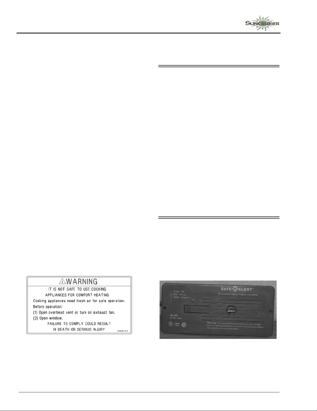
• The following warning label is located in the
cooking area to remind you to provide an
adequate supply of fresh air for combustion.
asphyxiation is greater when the appliance is
used for long periods of time. Failure to comply
could result in death or serious injury.
LP GAS LEAKS
The following procedures are located in the
vehicle near the range area. If you smell gas
within the vehicle, quickly and carefully perform
the procedures listed.
IF YOU SMELL PROPANE
• Extinguish any open flames, pilot lights, and
all smoking materials.
• Do not touch electrical switches.
• Shut off the gas supply at the tank valve(s) or
gas supply connection.
• Open doors and other ventilating openings.
• Leave the area until odor clears.
• Have the propane system checked and leakage
source corrected before using again.
Failure to comply could result in death or serious
injury.
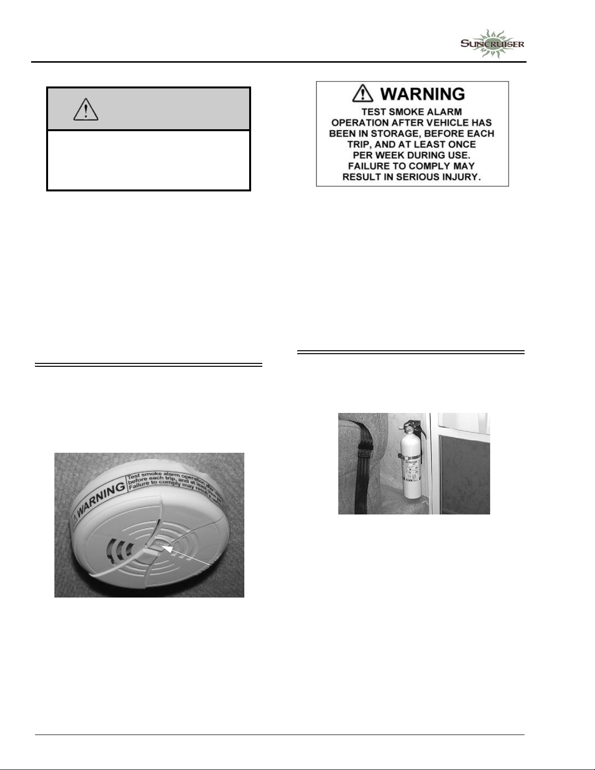
PROPANE GAS LEAK DETECTOR
Your coach is equipped with a propane gas
leak detector, similar to the one shown below.
The leak detector sounds an alarm if an unsafe
amount of propane gas is present inside the
coach.
Unlike homes, the amount of oxygen supply is
limited due to the size of the recreational vehicle,
and proper ventilation when using the cooking
appliance(s) avoids dangers of asphyxiation. It is
especially important that cooking appliances not
be used for comfort heating, as the danger of
2-2
Propane Gas Leak Detector
Because propane gas is heavier than air, the
leak detector is located on a cabinet face near the
floor of the coach.
Page 17

WARNING
EXPLOSION HAZARD: DO NOT use an
open flame to test for gas leaks. When
testing for gas line leaks with a soapy
water solution, DO NOT use a detergent
containing ammonia or chlorine. These
substances may generate a chemical
reaction causing corrosion to gas lines,
resulting in dangerous leak conditions.
Death or serious injury can result.
Power Connection
The propane gas leak detector is powered by
the house batteries. If the house/coach battery
switch is shut off or the battery cable is
disconnected from the batteries, the alarm will
not work. The propane gas leak detector fuse or
circuit breaker is located in the 12-volt house
electrical load center.
Because the propane gas leak detector is
connected to the house battery, it is always
drawing a small amount of current. Even though
this current draw is slight, it could drain the house
battery during storage periods when the house
battery will not be charged regularly by the
engine or shoreline.
Further Information
See the manufacturer’s information in your
InfoCase for further instructions on nuisance
alarms and care and testing of the propane gas
leak detector.
SECTION 2 –
SAFETY AND PRECAUTIONS
The best protection against carbon monoxide
entry into the vehicle body is a properly
maintained engine exhaust and ventilation
system. It is recommended that the exhaust
system and body be inspected by a qualified
motor home service center:
• Each time the vehicle is serviced for an oil
change.
• Whenever a change in the sound of the
exhaust system is noticed.
• Whenever the exhaust system, underbody , or
rear of the vehicle is damaged.
To allow proper operation of the vehicle’s
ventilation system, keep front ventilation inlet
grill clear of snow, leaves, or other obstructions
at all times. DO NOT OCCUPY A PARKED
VEHICLE WITH ENGINE RUNNING FOR
AN EXTENDED PERIOD.
Do not run engine in confined areas, such as a
garage, except to move vehicle into or out of the
area.
CARBON MONOXIDE ALARM
Your coach is equipped with a carbon
monoxide (CO) alarm located on the ceiling in
the bedroom area. The CO alarm is powered by a
9-volt battery and has a sensor that is designed to
detect toxic carbon monoxide gas fumes
resulting from incomplete combustion of fuel. It
will detect CO gas from any combustion source
such as the furnace, gas range/oven, water heater,
refrigerator, chassis engine, and electric
generator engine.
Press button to test
CARBON MONOXIDE WARNING
WARNING
Avoid inhaling exhaust gases, as they
contain carbon monoxide, which is a
colorless, odorless, and poisonous gas.
Death or serious injury can result.
Carbon Monoxide Alarm
2-3
Page 18
SECTION 2 –
SAFETY AND PRECAUTIONS
WARNING
Failure to replace this product by the
“REPLACE BY DATE” printed on the
alarm cover may result in death by
Carbon Monoxide poisoning.
Replacement
When replacing this alarm, we recommend
replacing only with the same model, or with one
that is also listed for RV application. We
recommend obtaining a replacement from your
Winnebago Industries® dealer.
Further Information
Please read the information provided by the
manufacturer, which is included in your InfoCase
for further information.
SMOKE ALARM
Your motor home is equipped with a smoke
alarm located on the ceiling in the lounge area.
The smoke alarm is powered by a 9-volt battery
and has a sensor that is designed to detect smoke.
Further Information
See the manufacturer’s information in your
InfoCase for further instructions.
Replacement
When replacing this alarm, we recommend
replacing only with the same model, or with one
that is also listed for RV application. We
recommend obtaining a replacement from your
Winnebago Industries® dealer.
FIRE EXTINGUISHER
A dry chemical fire extinguisher is located
near the main entrance door.
Push button
to test
Smoke Alarm
The following label is affixed to the smoke
alarm.
2-4
Fire Extinguisher
(Typical inst alla tion - your coach may
vary according to model and floorplan)
We recommend that you become thoroughly
familiar with the operating instructions displayed
on the side of the fire extinguisher and in the
information supplied in your InfoCase.
We also recommend that you inspect the fire
extinguisher for proper charge at least once a
month in accordance with National Fire
Protection Association (NFPA)
recommendations as stated on the label.
If the charge is insufficient, the fire
extinguisher must be replaced.
Page 19

SAFETY AND PRECAUTIONS
LOADING
SECTION 2 –
NOTICE
Do not test the fire extinguisher by
discharging it. Partial discharge can
cause leakage of pressure or contents,
which would render the unit inoperative
when needed. When using the fire
extinguisher , aim the spray at the base of
the fire.
Replacement
If for any reason you must replace the fire
extinguisher, the replacement must be the same
type and size as the one originally supplied in
your coach. We recommend obtaining a
replacement only from your Winnebago
Industries® dealer or a reliable RV parts supplier.
ELECTRICAL
• Careless handling of electrical components
can be fatal. Never touch or use electrical
components or appliances while feet are bare,
while hands are wet, or while standing in
water or on wet ground.
• Improper grounding of the vehicle can cause
personal injury . Do not plug the utility power
cord into an outlet which is not grounded and
do not adapt the plug to connect to a receptacle
for which it is not designed.
• Store or secure all loose items inside the motor
home before traveling. Possible overlooked
items such as canned goods or small
appliances on the countertop, cooking pans on
the range, or free-standing furniture items can
become dangerous projectiles during a
sudden stop.
• Be aware of GVWR, GAWR, and individual
load limit on each tire or set of duals (See
“Loading the Vehicle” in Section 12).
• Never load the motor home in excess of the
gross vehicle weight rating of the gross axle
weight rating for either axle.
MAINTENANCE
• Do not remove the radiator cap while engine
and radiator are still hot. Always check
coolant level visually at the see-through
coolant reservoir.
• Never get beneath a vehicle that is held up by
a jack only.
• Do not mix different construction types of
tires on the vehicle, such as radial, bias, or
belted tires, as vehicle handling may be
affected. Replace tires with exact size, type,
and load range.
EMERGENCY EXITS
• Do not attach an extension cord to the utility
power cord.
• Do not use any electrical device that has had
the ground pin removed.
• A void overloading electrical circuits. Replace
fuses or circuit breakers with those of the
same size and amperage rating only. Never
use a higher rated fuse or breaker.
• Use caution when handling or working near
electrical storage batteries. Always remove
jewelry and wear protective clothing and eye
covering. Avoid creating sparks.
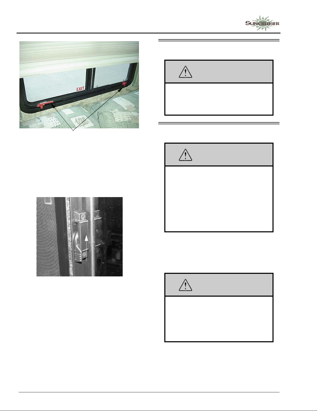
Escape Window
The bedroom escape window is secured by
two red safety latches at the bottom of the
window.
To open, lift both latches up and toward the
center of the window, then push outward near the
bottom of the window.
2-5
Page 20
SECTION 2 –
SAFETY AND PRECAUTIONS
Escape Window - Lift latch
handles upward to open
POWER SOFAS AND BEDS
WARNING
Keep people away from operating
mechanism and pinch hazard areas
during use. Failure to do so could cause
injury.
SLIDEOUT ROOMS
Using Slider Windows As Emergency Exits
Some coaches are required to have a slider
window as an alternate exit. This window will be
marked EXIT and have a red-handled latch.
Pull latch UP to slide window open
Most slider windows along the side of any
motor home can also be used as alternate
emergency exits, should the need arise.
To use a slider windows as an exit, first slide
the window open, then either slide the screen
open or push the screen material out, depending
on window construction.
WARNING
Your motor home may have more than
one slideout room. Understand which
switch operates which slideout room prior
to operation. Make sure all slideout rooms
are clear of people who could be harmed
or obstacles that could cause damage
prior to operating any slideout rooms.
Failure to observe can result in death or
serious injury.
Check inside and outside the vehicle to make
sure that there are no people who could be
harmed or obstacles that could cause damage due
to room activation.
WARNING
Keep all persons clear of the slideout
room and moving parts while extending or
retracting. Do not occupy the slideout
room while it is being extended or
retracted. Failure to observe can result in
death or serious injury.
2-6
Page 21

FORMALDEHYDE INFORMATION
Some of the materials used in this recreational
vehicle emit formaldehyde. Eye, nose, and throat
irritation, headache, nausea, and a variety of
asthma-like symptoms, including shortness of
breath have been reported as a result of
formaldehyde exposure. Reaction to
formaldehyde exposure may vary among
individuals. Elderly persons and young children,
as well as anyone with a history of asthma,
allergies, or lung problems may be at greater risk.
Research is continuing on the possible long-term
effects of exposure to formaldehyde. Inadequate
ventilation may allow formaldehyde and other
contaminants to accumulate in indoor air.
Ventilation to dilute the indoor air may be
obtained from a passive or mechanical
ventilation system. Always be sure to thoroughly
ventilate your recreational vehicle before and
during each use. High indoor temperatures and
humidity may raise formaldehyde levels. When a
recreational vehicle is in areas subject to high
temperatures, an air conditioning system can be
used to control indoor temperature levels. If you
have any questions regarding the health effects of
formaldehyde, consult your doctor or local health
department.
MOLD, MOISTURE, AND YOUR MOTOR HOME
What is Mold?
Molds are part of the natural environment.
They are as old as the Earth itself and mold
spores are almost everywhere at some level
waiting to grow. Mold plays a part of nature by
breaking down dead organic matter, such as
fallen leaves and dead trees. Indoors however,
mold growth should be avoided. Molds
reproduce by means of tiny spores. Those spores
are invisible to the naked eye and float
throughout the outdoor and indoor air. Because
of the nature of the use of a motor home, it is
natural for a motor home to be introduced into an
environment with mold spores.
SECTION 2 –
SAFETY AND PRECAUTIONS
Mold is a plant and requires its own special
environment to grow. That environment includes
organic materials, nutrients, moisture, and proper
temperature.
How Can I Avoid Mold?
To reduce the ability for mold to grow, you
must reduce what constitutes its growth
environment. Mold can grow with the smallest of
a nutrient base. Just small amounts of dirt or dust
on the carpet can be enough to allow the mold
process to begin. Keep the environment as clean
as possible. Vacuum the carpet. Clean food spills
thoroughly and quickly. Avoid grease buildup
near the stove or sink. Clean the exhaust fan
above the stove often.
Minimize moisture in your motor home and
keep humidity low. Clean spills quickly. Do not
allow condensation to build up. You can open
windows and vents to minimize condensation.
Use of the air conditioner can assist in removing
moisture from the air. Avoid leaks, but if leaks do
occur, make repairs promptly.
Avoid bringing mold into your motor home.
Plants, cloths, books, and other household items
may already have mold present. It is easy to
transfer mold into your motor home
environment.
Monitor your motor home. Periodically check
those hidden areas in corners, closets, and
cabinets to assure mold is not present.
What if I Find Mold?
If mold develops, clean the area with a
concentrate of soap and bleach. Items that
contain mold that cannot be cleaned should be
removed from the vehicle.
Can Mold Harm Me?
The effects of mold and airborne mold spores
may cause irritation to some people. Experts
disagree on the level of exposure that may cause
health concerns.
2-7
Page 22
SECTION 2 –
SAFETY AND PRECAUTIONS
If Mold Is Present, What Will
®
Winnebago Industries
If Winnebago Industries determines that mold
is present in the Winnebago®/Itasca® motor
home as a result of a manufacturing defect
reported to Winnebago Industries within the
limited warranty period, Winnebago will clean
the affected area(s) and/or replace affected items
as it deems necessary. This is the extent of
coverage provided by Winnebago Industries.
Winnebago Industries, however, will not assume
responsibility for mold deemed to be a result of a
motor home users lack of timely and appropriate
action to mitigate circumstances should a
problem occur.
If Winnebago Industries determines that mold
is present due to conditions it determines is not a
result of a manufacturing defect found within the
warranty period, Winnebago Industries will not
provide any financial assistance to the repair of
the condition.
Do?
ROOF AND LADDERS
WARNING
Stay off roof. Roof surface may be
slippery. Falling could result in death or
serious injury.
The ladder on your motor home is provided
for limited access to the roof.
Walking or working on the roof should be left
to qualified service personnel using proper safety
equipment in a safe environment. You should
only walk or work on the roof if you are qualified
and have created a safe environment.
For your safety, it is not recommended that
you store or carry items on the roof.
Before Using the Ladder
• Inspect the ladder to make sure it is not
damaged. Never use a damaged ladder.
• Keep the rungs of the ladder clean and dry
while in use. Never use the ladder when it is
raining, snowing, or icy. The rungs can
become slippery . Do not step onto the rungs if
the rungs are wet, or if your shoes are wet or
carry mud or debris that could result in a loss
of footing.
• Never ignore warning labels or weight limits
defined on your ladder. The following
warning label is located on or near the ladder:
WARNING
Do not exceed 225-lb. maximum weight capacity.
Misuse of ladder could result in death or serious injury.
See Operators Manual before using ladder.
• Maximum Capacity: 225 lbs.
• Do not overload. Ladder is intended for one
person.
• Make sure you are physically capable to
safely use the ladder . Strength, flexibility , and
stability are required.
• Be aware that the vehicle may sway as you
climb the ladder . Do not use the ladder in high
winds.
• As you climb the ladder, grasp the side rails
firmly and always use both hands. Keep your
body centered between the side rails. Do not
over-reach.
• Never allow children on the ladder.
• Do not transport items anchored to the
ladder. You could damage the ladder.
ROADSIDE EMERGENCY
Because of the size and weight of this vehicle
and its tires, and the possible complications
involved in tire changing, we strongly advise
obtaining professional road service to change a
flat tire whenever possible. However, if an
emergency requires you to change the tire
yourself, please exercise extreme caution and
read all tire changing information in the chassis
manual.
Never get beneath a vehicle that is held up by
a jack only.
2-8
Page 23

SECTION 2 –
SAFETY AND PRECAUTIONS
If You Get A Flat Tire
• DO NOT panic.
• Grip the steering wheel firmly and steer the
vehicle as straight as possible. Avoid quick
maneuvers. You may need to counter-steer to
compensate for “pull” created by the failed
tire.
• DO NOT stomp on the brake. This abruptly
shifts the vehicle’s weight forward, making it
nose-dive and pull toward the blown-out side.
• DO NOT jerk your foot off the accelerator.
Just ease back on the accelerator slowly and
gently to continue momentum. The deflated
tire will slow the vehicle.
• If you must change lanes to get to a safe
stopping place, use your signals to warn other
motorists and change lanes smoothly and
carefully after you are certain the lane is clear .
• Let the vehicle coast to a stop, gently steering
to a safe stopping place off the traffic lanes of
the road. Do not worry about damaging the
tire or wheel rim by driving on it. A tire or
wheel replacement is cheaper than damaging
the vehicle or injuring yourself.
• When you have come to a stop, activate your
hazard flashers to warn other motorists, then
exit the vehicle carefully.
• Set out flares or other warning devices.
Check your tires for proper inflation before
each trip and at least once a month with an
accurate tire gauge.
Recovery Towing
When calling a professional towing service,
we recommend that you advise them of your
coach length and approximate front axle weight
listed on your Vehicle Certification Label. This
will allow the towing operator to determine the
proper towing equipment to use.
We recommend that you ask for an underlift
(wheel lift or frame lift) type towing assembly for
safe towing.
Winnebago Industries® does not assume
responsibility for damage incurred while towing
this vehicle.
NOTE: Consult the chassis manual for any
additional towing instructions or
precautions provided by the chassis
manufacturer.
NOTICE
Do not lift on bumper . Damage will result
to front end body parts.
WARNING
Stay out from beneath the motor home
while it is suspended by the towing
assembly. Do not allow passengers to
occupy a towed vehicle. Death or serious
injury can result.
JUMP STARTING
If your coach will not start from the chassis
battery, try using the battery boost switch to
divert power from the house batteries to the
starter. (See either “Battery Boost Switch” or
“Aux Start Switch”).
If you wish to try jump starting the engine
using another vehicle or booster system, see your
chassis manual for connecting jumper cables to
the automotive electrical system.
NOTICE
Do not attempt to push start this vehicle.
Damage to the transmission or other
parts of the vehicle will occur.
2-9
Page 24
SECTION 2 –
SAFETY AND PRECAUTIONS
ENGINE OVERHEAT
If you see or hear steam escaping from the
engine compartment or have any other reason to
suspect an extreme engine overheating condition,
pull the vehicle over to the roadside as soon as it
is safe to do so, stop the engine, and get all
passengers out of the vehicle.
NOTICE
Operating a vehicle under a severe
overheating condition can result in
damage to the vehicle.
For information on what to do in case of
overheating, consult your chassis manual.
2-10
Page 25
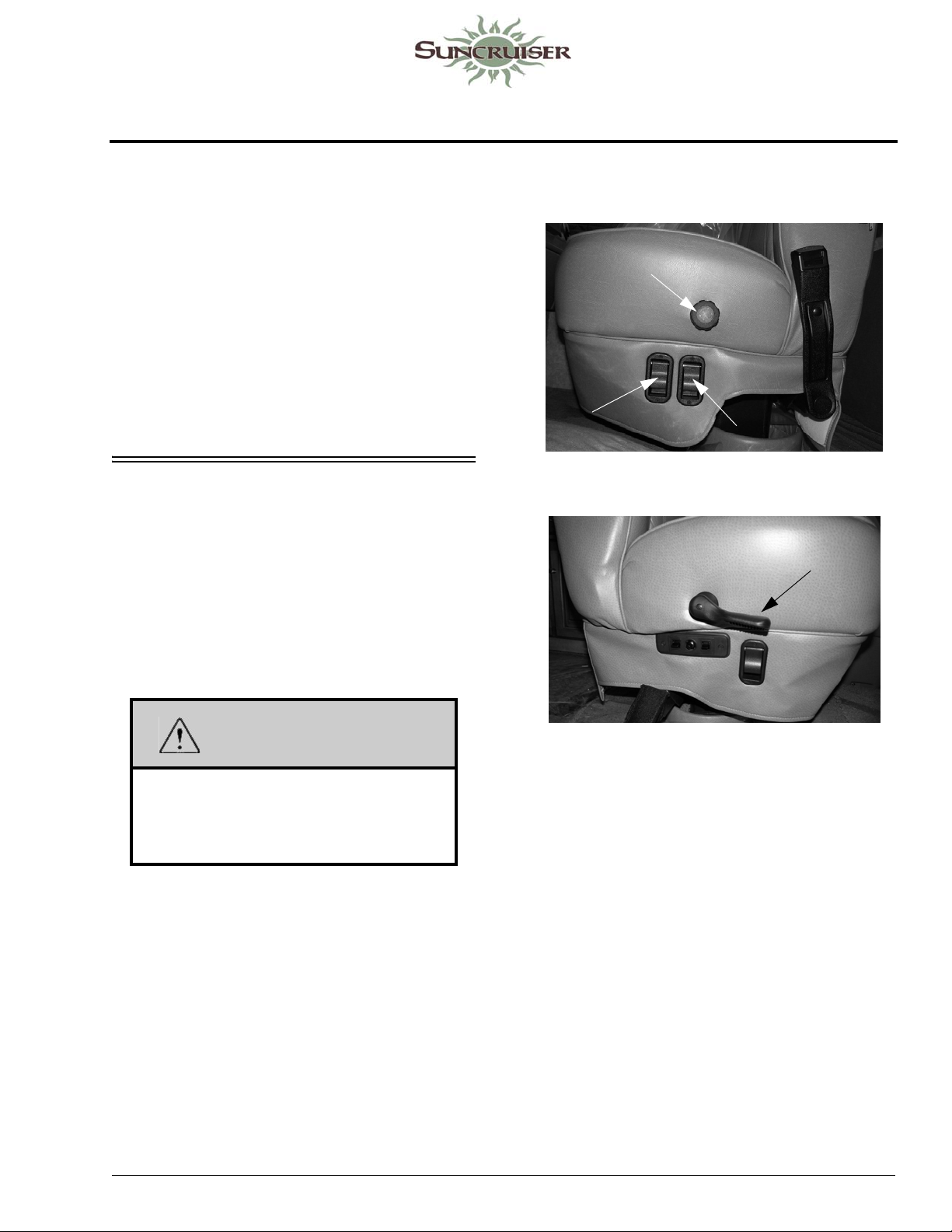
SECTION 3 – DRIVING YOUR MOTOR HOME
The information in this section refers only to
features installed or adapted to the dash and
driver compartment area by Winnebago
Industries®. It also includes passenger seating in
the living area of the coach.
Further Information
See the chassis manual in your InfoCase for
all original chassis related controls,
instrumentation, switches, and other features.
This includes items such as transmission, parking
brakes, cruise control, gauges, wipers, lights, etc.
SEATS – DRIVER/CO-PILOT
The driver and co-pilot seats may be
independently adjusted to suit individual
preference.
The seats may be swiveled to provide easy
entrance and exit. The swivel feature also allows
the seats on most models to be turned toward the
living area for additional seating while the unit is
parked.
Front Seats
Turn Knob
for Lumbar
Tension
Lift to Swivel
Lift to Slide
-Typical View
Lift to
Recline
WARNING
Assure seat is in its forward and locked
position for travel. Do not adjust seat
while vehicle is in motion. Failure to
comply may result in injuries.
-Typical View
Multi-Adjustable Power Seat
–If Equipped
The power seat controls are located on the
lower right hand side of the driver seat base.
5 - DASH / AUTO
3-1
Page 26
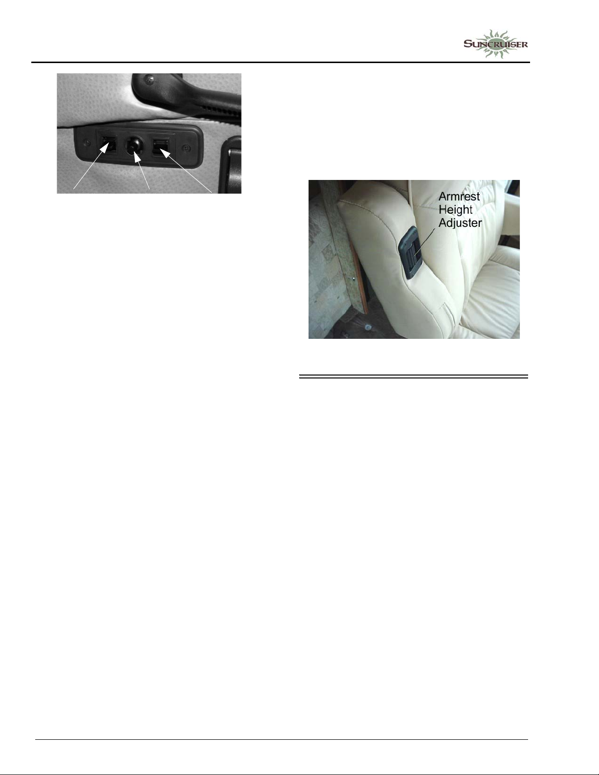
SECTION 3 –
DRIVING YOUR MOTOR HOME
Armrest Adjustment
-If Equipped
The armrests may be swung upward out of the
way for easy exit or access to the front seats. A
roller on the underside of the front of the armrest
also lets you adjust the resting angle for personal
comfort, whether the seat is upright or reclined.
Hip Area
- Up/Down
Main Seat
Position
- Up/Down
- Fore/Aft
-Typical View
Knee Area
- Up/Down
To Face Driver’s Seat Rearward
Manual Seat
• Tilt the steering wheel all the way up.
• Put the left armrest down.
• Swivel the seat to the right until it just contacts
the steering wheel, then slide the seat ahead all
the way.
• Lift the recliner lever and let the seat back tilt
ahead to clear the steering wheel.
• Swivel the seat the rest of the way to face the
living area.
• Tilt the steering wheel down.
• Reverse the procedure to face the seat
forward.
Power Seat
• Tilt the steering wheel all the way up and put
the left armrest down.
• Move the seat rearward fully and then ahead a
few inches.
-Typical View
PASSENGER FOOTREST
-If Equipped
The co-pilot seat is equipped with a manual
footrest that provides greater utility to be used as
a lounge chair when rotated for television
viewing or as part of a lounge conversational
area.
• To extend footrest, lift black footrest lever
(located on right-hand side of seat).
• T o retract footrest, push downward with your
legs and the footrest will close.
• Swivel the seat to the right until it just contacts
the steering wheel, then move the seat ahead
all the way to clear the steering wheel.
• Swivel the seat the rest of the way to face the
living area.
• Position the tilt wheel down and to provide
maximum clearance to recline the seat.
• Reverse the procedure to face the seat
forward.
3-2
Page 27
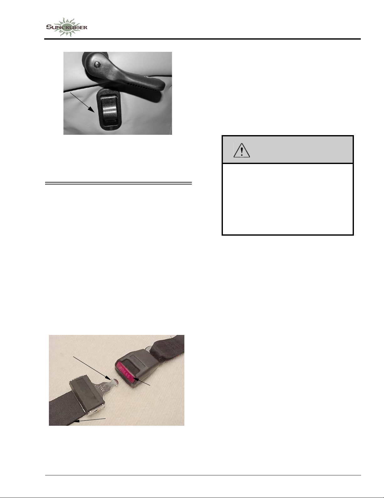
Passenger Footrest Lever
(Located on right-hand
side of passenger seat)
-Typical View
SEAT BELTS
Seats intended for occupancy while the
vehicle is in motion are equipped with seat belts
for the protection of the driver and passengers.
Lap Belts
The lap belts must be worn as low as possible
and fit snugly across the hip area. Always sit
erect and well back into the seat. To gain full
protection of the safety belt, never let more than
one person use the same safety belt at any one
time, and do not let the safety belts become
damaged by pinching them in the doors or in the
seat mechanism. After any serious accident, any
seat belts which were in use at the time must be
inspected and replaced if necessary.
1- Insert tab into buckle slot until it “clicks” and is locked
3- Press to
release
2- Pull strap to tighten
SECTION 3 –
DRIVING YOUR MOTOR HOME
To Fasten
Be sure belt is not twisted. Grasp each part of
the belt assembly and push tongue into buckle.
Adjust to a snug fit by pulling the loose end away
from the tongue.
To Release
Press button in center of buckle and slide
tongue out of buckle.
WARNING
Snug and low belt positions are essential.
This will ensure that the force exerted by
the lap belt in a collision is spread over the
strong hip area and not across the
abdomen, which could result in serious
injury.
Only seats equipped with seat belts are to
be occupied while vehicle is in motion.
Lap/Shoulder Belts
Fastening
Hold the belt just behind the tongue using the
hand nearest to the door. Next, bring the belt
across the body and insert the tongue into the
buckle until the latch engages.
Unfastening
Press the release button in the buckle. Hold
onto the tongue when you release it from the
buckle to keep it from retracting too rapidly.
When the lap-shoulder belt is in use, the lap
belt must ride low across the hip area and the
shoulder belt must ride diagonally over the
shoulder toward the buckle.
The shoulder belt is designed to lock only
during a sudden stop, sudden body movement or
a collision. At all other times it will move freely
with the occupant.
Adjustment
To lengthen belt, swivel the tab end at a right
angle to belt and pull strap to desired length. To
shorten, pull loose end of belt.
3-3
Page 28

SECTION 3 –
DRIVING YOUR MOTOR HOME
WARNING
Never wear the shoulder belt in any
position other than as stated above.
Failure to do so could increase the
chance or extent of injury in a collision.
Seat Belt Care and Cleaning
• Be careful not to damage the belt webbing and
hardware. Take care not to pinch them in the
seat or doors.
• Inspect the belts and hardware periodically.
Check for cuts, frays, and loose parts.
Damaged parts should be replaced. Do not
remove or modify the belt system.
• Keep belts clean and dry. If the belts need
cleaning, use only a mild soap and water
solution. Do not use hot water. Do not use
abrasive cleaners, bleach, or dyes. These
products may weaken the belts.
• Replace any belt assembly that was used
during a severe impact. Replace the complete
assembly even if damage is not apparent.
2. Make sure that it will attach to your vehicle and restrain your child securely and conveniently so that you are able to install it correctly each time it is used.
3. Be certain that it is appropriate for the child's height, weight, and development. The instructions and/or the regulation label attached to the restraint typically provides this information.
4. Review the instructions for installation and use of the restraint. Be sure that you understand them fully and can install the restraint properly and safely in your vehicle.
Tether Anchor Loop
-If Equipped
If your coach has a dinette, it may be equipped
with a child seat tether anchor loop located on the
floor directly behind the forward facing dinette
seat.
Tether Anchor Loop
CHILD RESTRAINTS
-If Equipped
A properly installed and secured child
restraint system can help reduce the chance or
severity of personal injury to a child in an
accident or during a sudden maneuver. Children
may have a greater chance of being injured in an
accident if they are seated in a child restraint
system which is not properly secured.
A child restraint system is designed to be
secured in a vehicle seat by a lap belt or the lap
belt portion of a lap-shoulder belt.
When purchasing a child restraint system,
follow these guidelines:
1. Look for the label certifying that it meets all
applicable safety standards.
NOTE: The dinette table must be in the lowered
position when a child seat is in use.
3-4
Page 29
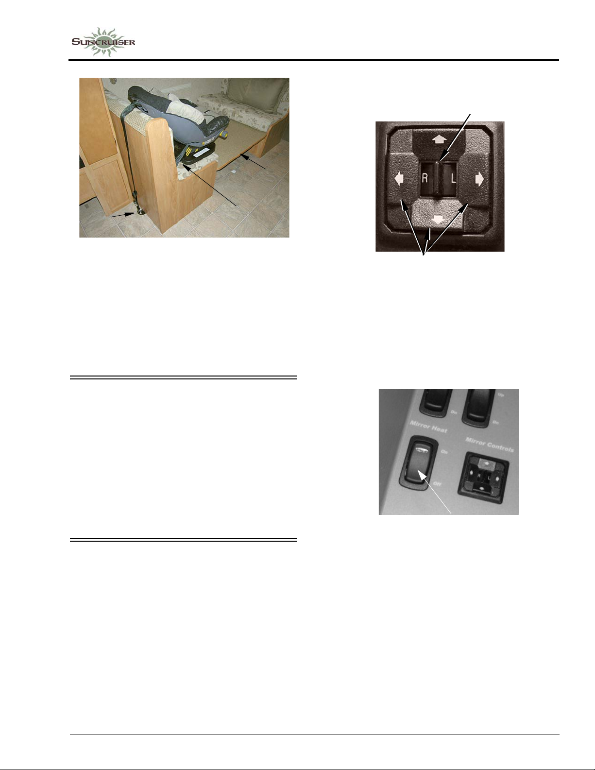
SECTION 3 –
DRIVING YOUR MOTOR HOME
Move Selector Switch L or R to select mirror.
Center “neutral” position disables arrows
to avoid unintentionally moving a mirror
1
2
1. Lower the dinette table.
2. Route the tether over the top of the dinette seat
back and hook it to the anchor loop on the floor .
3. Fasten the lap belt.
3
Further Information
See the child seat manufacturer’s specific
instructions for proper attachment and
adjustment of the tether and seat belts.
KEYONE™ LOCK SYSTEM
-If Equipped
Your coach is equipped with the KeyOne lock
system. A single key will open every door lock in
the entire vehicle (except the security deadbolt
lock on the entrance door).
The key number for your coach is registered in
our factory database, so if you ever lose your
®
keys, any Winnebago Industries
dealership can
order a new key for you.
MIRRORS – POWER ELECTRIC
–If Equipped
Always adjust mirrors for maximum rear
visibility before driving off. Make sure the seat is
adjusted for proper vehicle control and that you
are sitting back squarely into the seat.
Press Arrow Buttons to move
mirror surface in direction indicated
Mirror Heaters
The mirrors may also contain heating
elements to de-fog or de-ice the mirror glass
during cold weather operation. An ON-OFF
switch for the mirror heaters is located near the
remote mirror controls.
Mirror Heat Switch
(Located on driver side trim panel)
-Typical View
Mirror Arm/Head Adjustment
If you cannot adjust a mirror properly using
the control switch, the mirror may need a coarse
adjustment by rotating the mirror head.
Mirror Adjustment Control
The mirror control is located on the driver side
armrest panel or the dash. The ignition key must
be on to adjust the mirrors.
3-5
Page 30
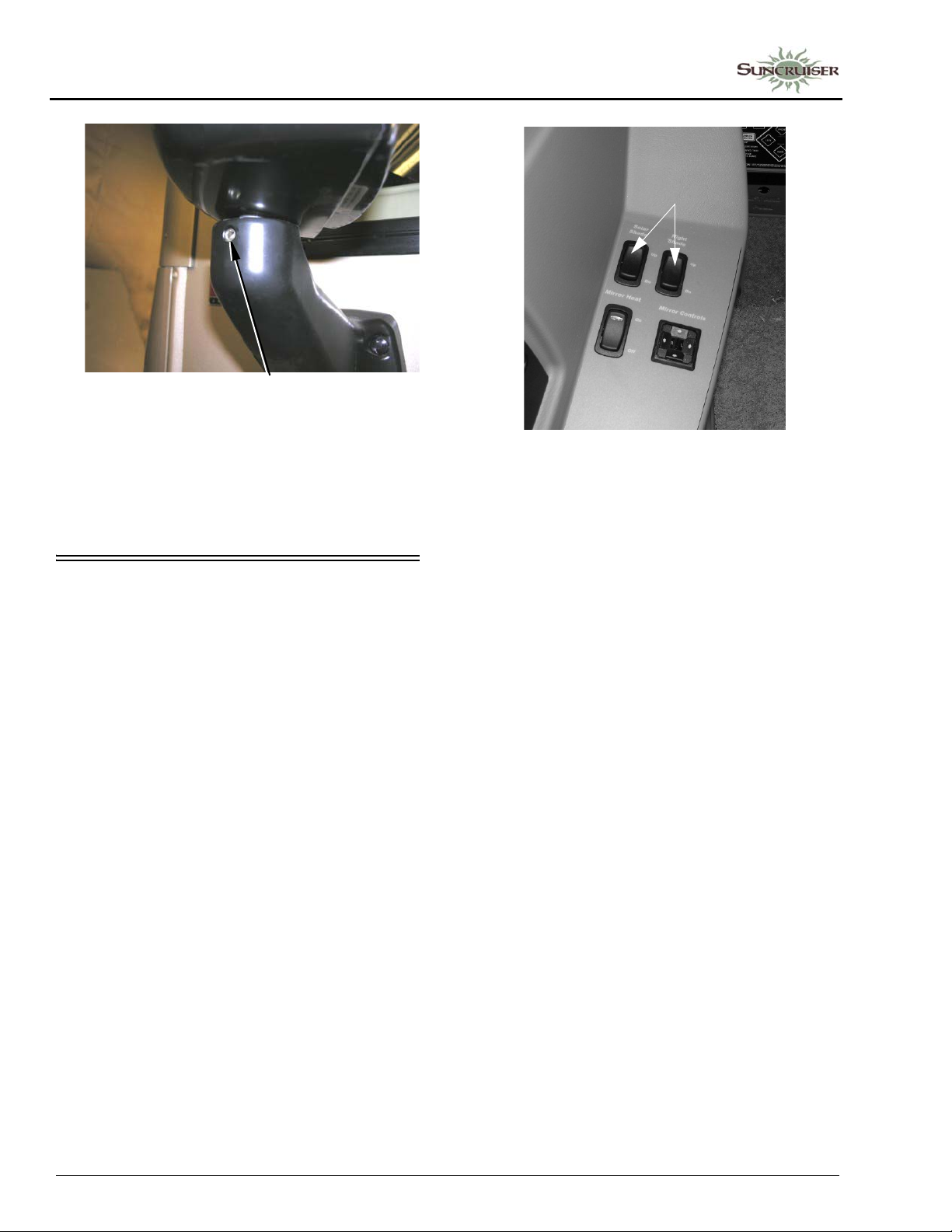
SECTION 3 –
DRIVING YOUR MOTOR HOME
Mirror Head Pivot Lock
• Loosen Allen head set
screw to pivot mirror head
(Torque 75-100 in/lbs)
NOTE: Set screws may be located on the
opposite side of the mirror arm.
Passenger side mirror is similar.
12-VOLT FRONT DROP-DOWN SOLAR/NIGHT SHADE
Your coach is equipped with a 12V Front
Drop-Down Solar/Night Shade that provides
privacy and solar heat protection as well as a
sunvisor feature.
The power switches for the 12V Front DropDown Solar/Night Shade are located on the dash
or driver side trim panel, depending on model.
12-Volt Front Drop-Down Solar/
Night Shade Switches
-Typical View
Press the Solar Shade (black) or the Night
Shade (white) switch up or down to adjust the
shade to the setting that best suits your needs.
Dual range motors provide lowering of either
two shades to visor height restriction when the
ignition is ON and lowers completely to cover the
entire windshield when the ignition is OFF.
The Chassis Battery Disconnect switch must
be ON to supply power to the solar/night shade.
NOTE: If power is gradually drained and falls
below the lower limit of 11-volts, the
motors could lose their electronic Set
Limits and will require reprogramming
once normal power has been restored.
Refer to the Solar/Night Shade
manufacturer’s information provided in
your InfoCase.
3-6
Further Information
Refer to the manufacturer’s user guide
provided in your InfoCase for complete operating
instructions, troubleshooting tips, and
maintenance care.
Page 31
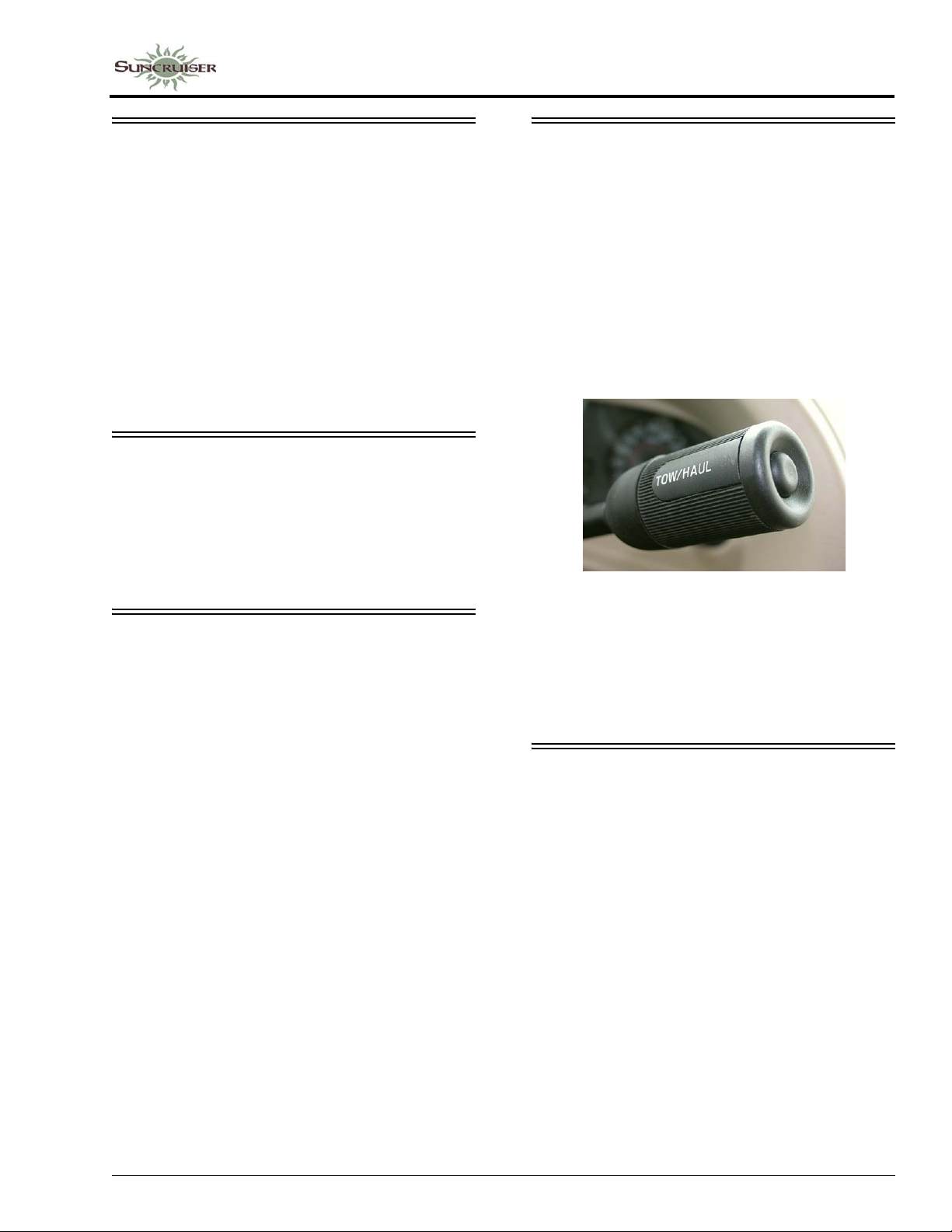
SECTION 3 –
DRIVING YOUR MOTOR HOME
BRAKE-SHIFT INTERLOCK
Ford® Chassis
The Brake-Shift Interlock is a safety feature
that prevents the shift lever from being moved
from the Park position unless the ignition is ON
and the service brake pedal is pressed.
NOTE: If the brake light fuse is blown, the
interlock feature will not work properly
and an alternate method must be used.
See the chassis manual provided in your
InfoCase for detailed instructions on
what to do in this situation.
PARK BRAKE – FOOT PEDAL
Ford® Chassis
The park brake foot pedal and release lever are
located beneath the left side of the dash.
Step the pedal down fully to apply and pull the
brake release knob to disengage.
FUEL PUMP SHUT-OFF SWITCH
Ford® Chassis Only
Vehicles built on Ford chassis are equipped
with an inertial-type switch that shuts off the fuel
pump in the event of collision. This switch must
be manually reset to resume the fuel supply to the
engine.
See the chassis manual provided in your
InfoCase for location and reset procedures for
this switch.
NOTE: It is possible to accidentally trigger the
fuel pump shut-off switch by abruptly
striking an object such as a curb or
parking block. If your vehicle exhibits
symptoms of running out of fuel
immediately after such an occurrence,
the fuel pump shut-off switch may need to
be reset.
See your chassis manual for additional
information.
TOW/HAUL TRANSMISSION MODE
Ford® Chassis only
This mode locks out Overdrive and helps
reduce gear “hunting” by the automatic
transmission while towing. It also improves
power delivery and uses engine braking to help
control vehicle speed when descending hills.
This mode may also be useful when the coach
is fully loaded or when driving into a strong
headwind.
• Press the button at the end of the shift
lever to engage Tow/Haul Mode
when pulling a trailer or tow vehicle
Further Information
See the chassis manual in your InfoCase for
further operating instructions and cautions.
HAZARD WARNING FLASHERS
The hazard warning flashers provide
additional safety when the vehicle must be
stopped on the side of the roadway and presents a
possible hazard to other motorists. When the
flashers are on, it serves as a warning to other
drivers.
Further Information
See your chassis manual for instructions on
activating, operating, and canceling hazard
warning flashers.
3-7
Page 32
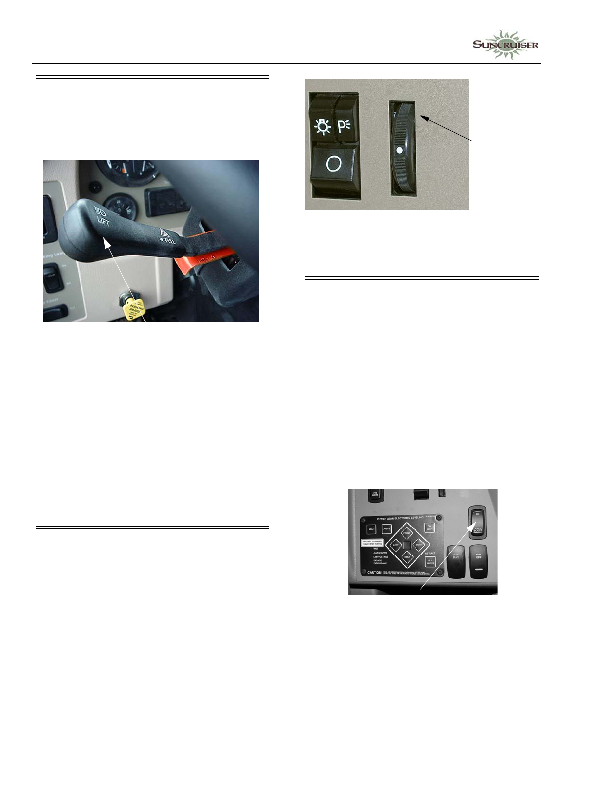
SECTION 3 –
DRIVING YOUR MOTOR HOME
SIGNAL LEVER/HEADLIGHT HIGH-LOW BEAM
The signal lever controls the turn signals and
headlight high/low beams.
Turn Signals/High-Low Beams
(Typical View - your coach may differ
depending on model)
• Move multi-function lever upward for right
turn signal and downward for left turn signal.
An audible chime will alert you when the
signals are flashing.
• Pull end of handle toward you to switch
headlight high/low beams.
Further Information
See your chassis manual for further operating
instructions and features.
Roll panel light dimmer wheel upward fully to turn driver side map light on.
Further Information
See the chassis manual in your InfoCase for
further information on this switch.
BATTERY BOOST SWITCH
The Battery Boost switch can be used to draw
emergency starting power from the house
batteries to start the engine if the chassis battery
is discharged.
Press and Hold the Battery Boost switch in the
ON position while turning ignition key for
emergency starting power.
NOTE: The House/Coach Battery Disconnect
switch near the entrance door must be
ON and house batteries must be
sufficiently charged for this feature to
work.
MAP LIGHT SWITCH
Turn the driver side map light on using the
Panel Dim thumbwheel. Roll it up to maximum
position until you feel it click into the map light
“On” position.
3-8
Battery Boost Switch
(Located on dash)
-Typical View
• If chassis battery is discharged,
press and hold while turning
ignition key for emergency starting
power.
Page 33
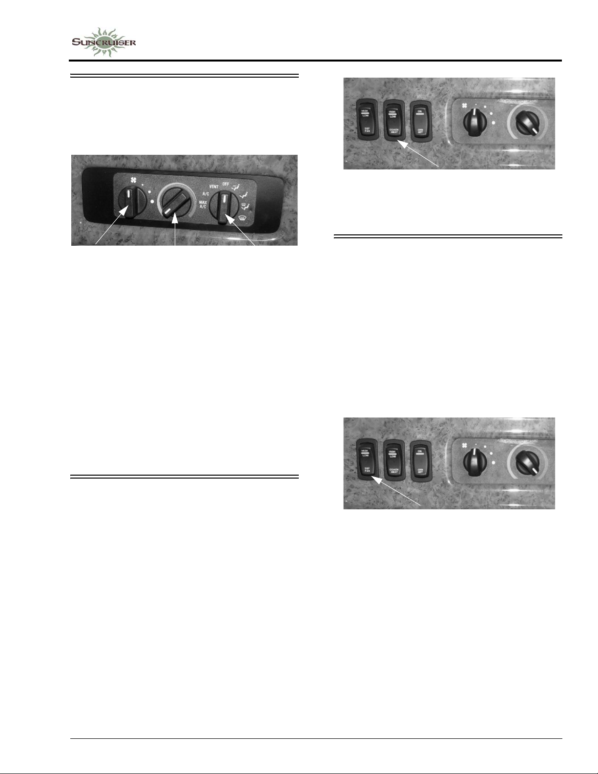
AIR CONDITIONER/HEATER – AUTOMOTIVE (DASH)
Controls for the air conditioner, heater,
defroster, and vent are located on the dash.
SECTION 3 –
DRIVING YOUR MOTOR HOME
Coach Heat Switch
(Located on dash)
-Typical View
Blower
Control
NOTE: The dash air conditioner/heater is not
designed to heat and cool the entire
interior of the coach, but is intended only
to provide heating and cooling for the
cab area.
A small amount of air will blow out of all
of the defrost and dash vents regardless
of the mode setting.
Temp
Control
Mode
Selector
Further Information
See the manufacturer’s user guide provided in
your InfoCase for complete operating
instructions.
HEATER – REAR COACH (AUTOMOTIVE)
–If Equipped
To provide auxiliary automotive system heat
to the rear of the vehicle while driving, turn the
rear heater fan switch to the desired speed. The
switch has three positions: High (up), Low
(down), and the middle position is Off.
DEFROST FANS
-If Equipped
The two-speed auxiliary fans are intended to
assist the automotive windshield defroster
system in clearing fog and frost in cold weather
or humid conditions.
• HIGH - For maximum defrost output, press
the Defrost Fan switch UP.
• LOW - For lower defrost output, press the
Defrost Fan switch DOWN.
• The middle position on the switch is OFF.
Defrost Fan Switch
(Located on dash)
-Typical View
3-9
Page 34
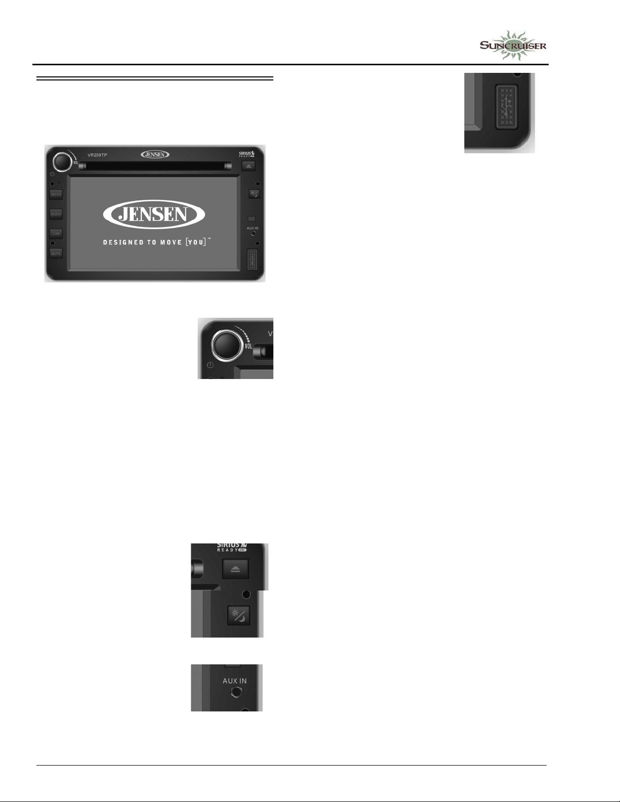
SECTION 3 –
DRIVING YOUR MOTOR HOME
RADIO IN-DASH/REARVIEW MONITOR SYSTEM
–If Equipped
Basic Operating Instructions
• POWER ON/OFF - Push
to turn ON or OFF. Push
and hold to turn screen OFF .
Touch screen to turn back
ON.
• MENU - Press to access USER SETTING
MENU. Press and hold access SYSTEM
SETUP MENU.
• AUDIO - Press and hold access AUDIO
MENU. Press to return to current playback
mode.
• CAM - Press to access CAMERA mode.
Press and hold access CAMERA SETTINGS
MENU.
• MUTE - Press to MUTE audio.
• EJECT - Press to EJECT
CD.
• USB - Connect a USB Jump
Drive. NOT FOR IPOD
CONTROLS.
Rearview Monitor
The rearview monitor feature of this system
lets you see what is directly behind your coach
for safety and maneuvering assistance. Sideview
cameras also allow you to see what is beside you
before turning or changing lanes.
The monitor screen “wakes up” automatically
when transmission is shifted into reverse. A
microphone built into the rear camera lets you
hear warning sounds or verbal directions from an
assistant.
Sideview Cameras
-If Equipped
The sideview cameras activate with the
corresponding turn signals and replace the rear
camera view on the monitor until the turn is
completed or the signal lever is canceled
manually.
Satellite Radio
–If Equipped
Your coach may be equipped with a Sirius®
satellite radio receiver that plays through your
radio.
See the receiver manufacturer’s information
in your InfoCase for programming and operating
instructions.
• DAY/NIGHT - Press to
switch between stored
DAY/NIGHT user settings.
Press and hold to access
AUTO DAY/NIGHT adjust.
• AUX IN - Connect portable
audio player.
3-10
NOTE:If your Sirius tuner is not activated,
follow the instructions in the radio
owners manual in your InfoCase for the
phone number to call and procedure to
access the Sirius Tuner ID Number
(ESN).
Page 35
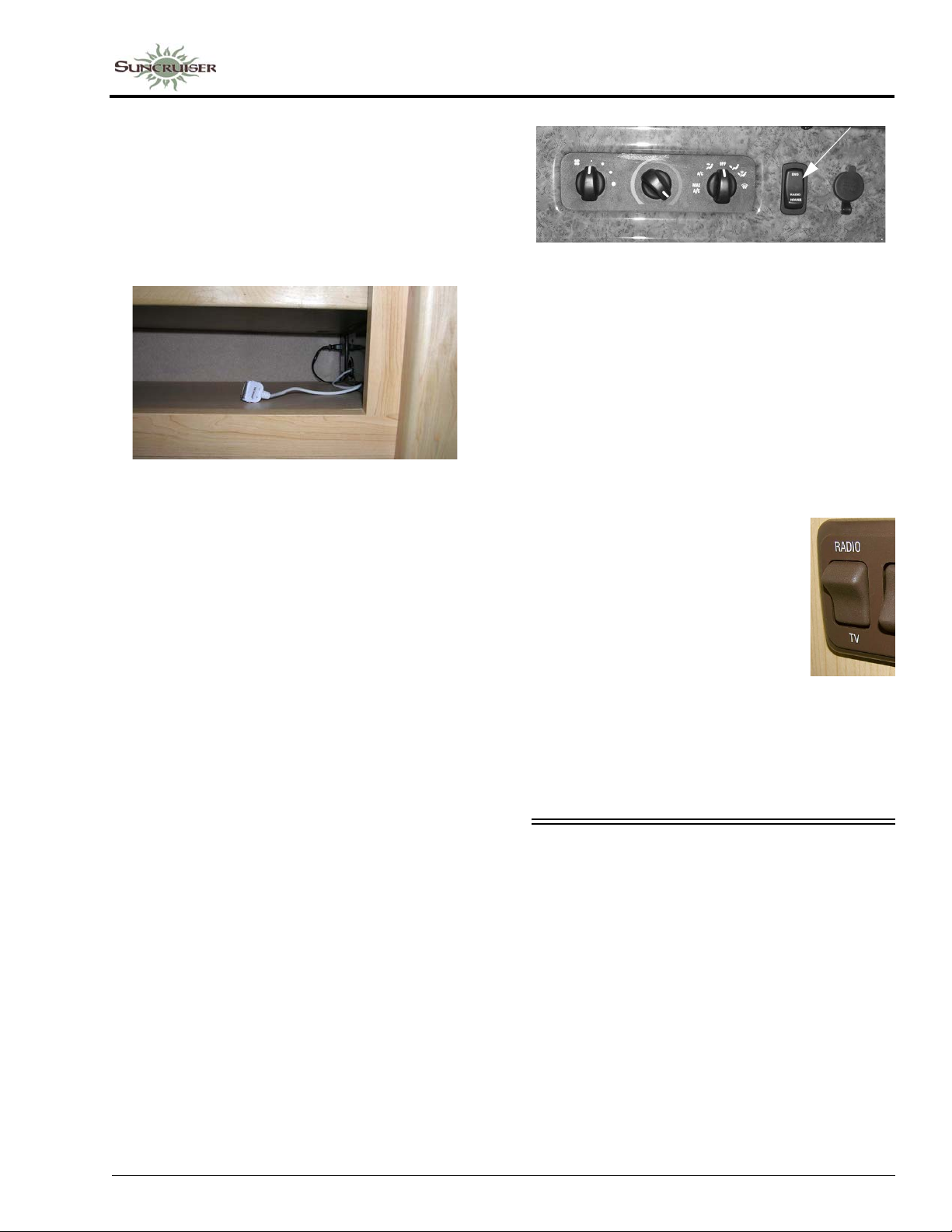
iPod Cable
-If Equipped
Your coach may be equipped with a cable to
connect your iPod to play through your dash
radio. This cable is in the overhead compartment
above the driver’s seat. The cable is shown in the
following photo.
-Typical View
SECTION 3 –
DRIVING YOUR MOTOR HOME
Radio Power Switch
(Located in dash area)
-Typical View
• Press HOUSE to listen to the radio while
parked without the ignition key on.
• Press ENGINE to listen while driving.
Radio Sound through Deluxe Sound Speakers
–If Equipped
See the manufacturer’s information in your
InfoCase for operating instructions.
Radio Remote Control
A hand-held remote control for the radio lets
you change radio stations or CD selections from
a distance for your convenience. The remote
control is included in your InfoCase.
Radio Power Switch
The Radio Power switch lets you connect the
dash radio to the coach batteries with the ignition
switch turned off for listening while parked. This
prevents accidental draining of the chassis
battery with prolonged use of the radio.
NOTE:The Coach/House Battery Disconnect
switch must be on while listening to the
dash radio because the audio relay is
powered by house batteries. If the Coach/
House Battery Disconnect switch is off,
the speakers will not emit sound.
To Listen to the Dash Radio through the
Deluxe Sound Speakers:
• Press the Speaker Selector
switch to RADIO position to
connect the dash radio to the
deluxe sound speakers. The
Speaker Selector switch is
located near the DVD player.
• Adjust volume with radio
buttons or radio remote.
Further Information
See the radio/rearview monitor reference
guide provided in your InfoCase for specific
instructions provided by manufacturer.
SIRIUS® PLUG AND PLAY SATELLITE RADIO
–If Equipped
(Located inside the driver or passenger
side overhead compartment)
Take Sirius Plug and Play on the go - in your
RV, at home, the office, other vehicles, or
anywhere else! It is featured with universal
docking capability so you can easily move Sirius
to different locations and enjoy your favorite
programming (separate docking station
included).
3-11
Page 36
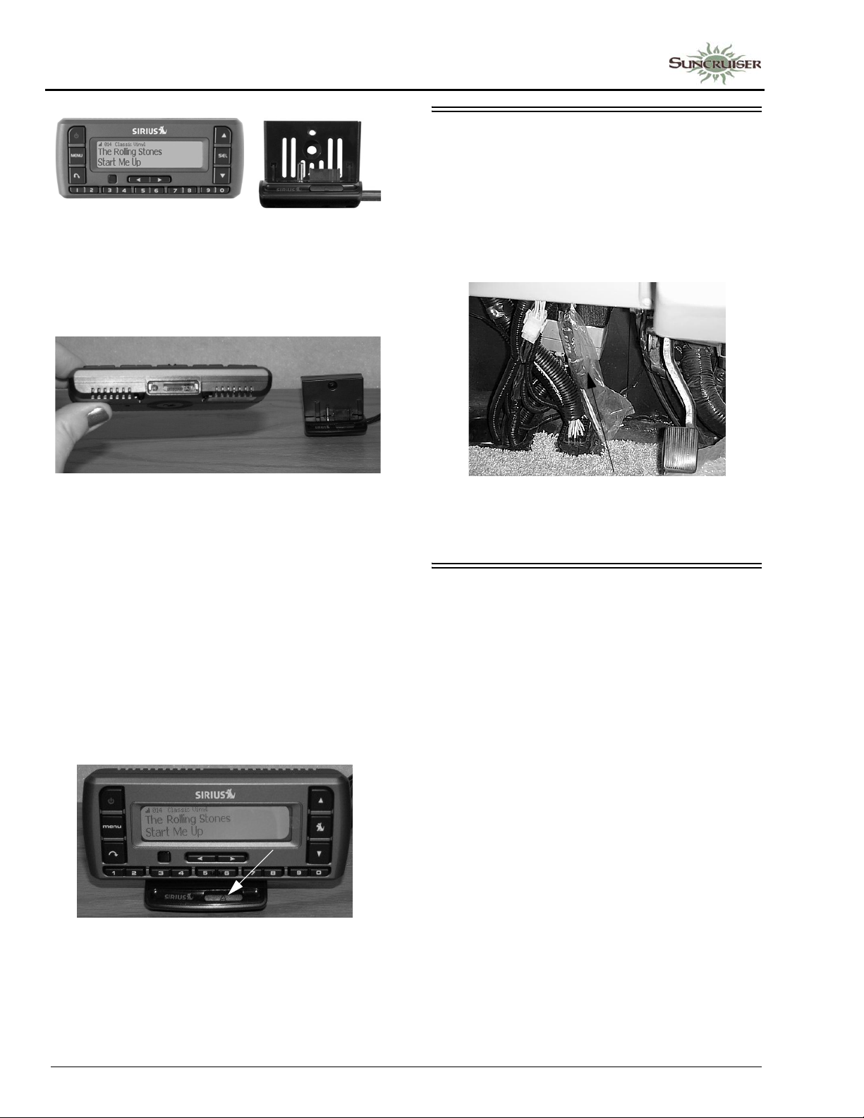
SECTION 3 –
DRIVING YOUR MOTOR HOME
To install the satellite unit, place your Sirius
radio into the docking station, aligning the tabs at
the edges of the the radio adapter with the
grooves in your radio. Gently push the radio
down until it is fully seated in the docking station.
CB RADIO POWER WIRING
Your coach is pre-wired for CB radio power
connection. The wires are located beneath the
dash to the left of the steering wheel.
Look for a pair of wires - yellow (+) and white
(-) with connectors and flag labels suspended
from the wiring harness.
For complete operating instructions, see
the dash radio and satellite radio receiver user
guide provided in your InfoCase.
When your Sirius radio is connected via the
SiriusConnect Docking Kit to the dash radio, the
buttons and controls of the Sirius radio will be
disabled, and a SiriusConnect message or logo
will be displayed.
To remove the satellite unit from the docking
station, press the release button while pulling the
radio out of the docking station. You can now
take your Sirius Plug and Play and install it in
your car with the supplied car kit.
CB Power Wires
(in plastic sheath)
Typical View - your coach may differ
FRONT SERVICE ACCESS
(HOOD)
The hood panel can be opened for access to
service items such as the engine oil dipstick, oil
fill, radiator fill, power steering reservoir, and
windshield washer fluid reservoir.
The hood latches are located behind the
bottom edge of the hood panel near both ends of
the grille. Squeeze or pull both latch handles at
the same time toward the hood panel to release
the latches. Then pull the hood panel outward
slightly and raise it up into the open position.
Further Information
See the dash radio/satellite radio receiver user
guide provided in your InfoCase for complete
operating and installation instructions.
3-12
Page 37
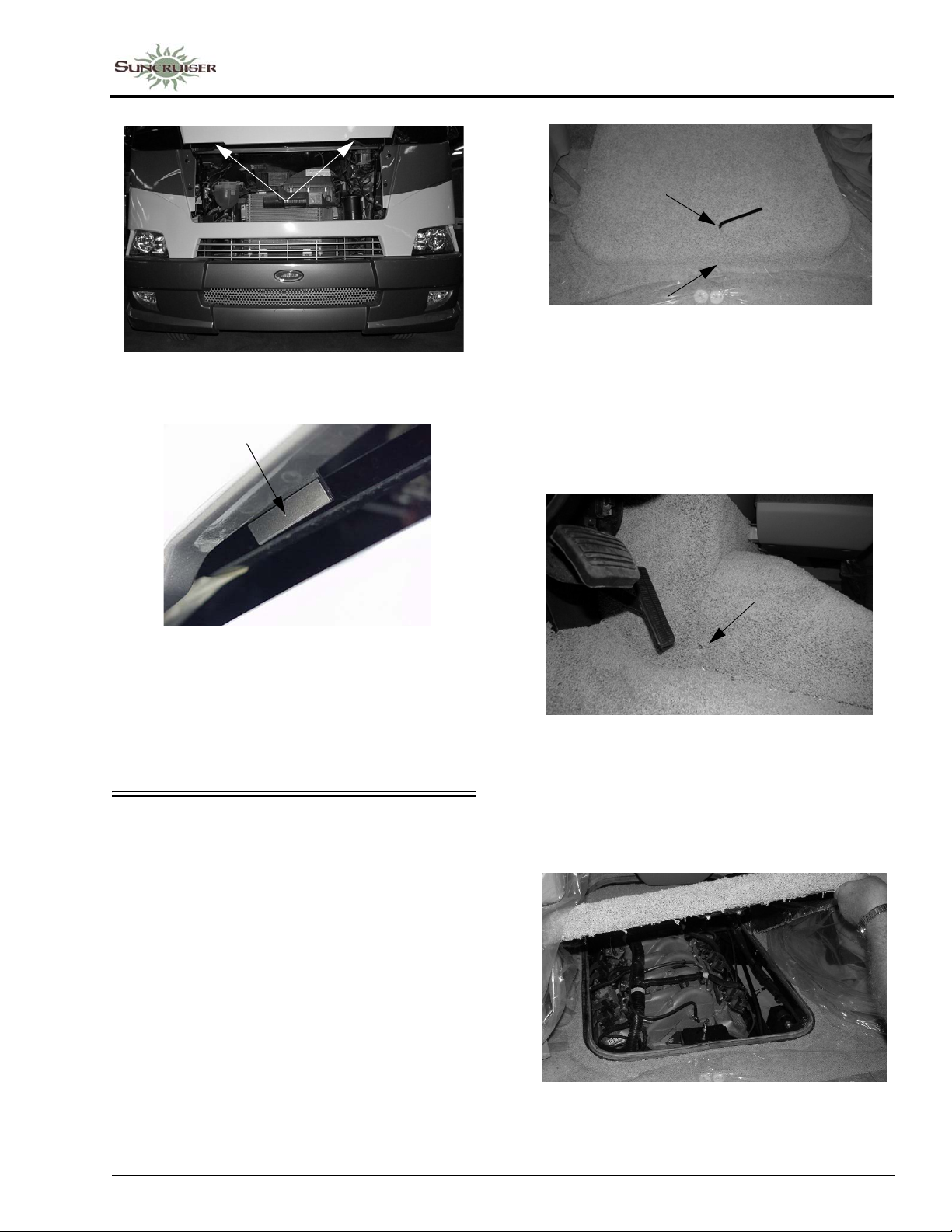
Latch Handle Locations
-Typical View
SECTION 3 –
DRIVING YOUR MOTOR HOME
• Insert hex wrench into the hole on the top
center of the engine cover (as shown) or
the front edge of engine cover to unlatch
-Typical View
NOTE: On some models there may also be
screws to remove at the lower front
corners. See following photo.
Squeeze latch handles toward hood
panel and raise hood into open position
To close the hood, pull downward and swing
inward. Press top edge of hood panel inward
firmly with palms of your hands to ensure proper
latching.
ENGINE ACCESS – INTERIOR
Front Engine Cover
• To remove the engine cover, insert the
supplied hex wrench into the hole in the top
center or the front edge of the engine cover
(depending on model).
Turn the hex wrench to the left (counterclockwise) to unlatch.
• Remove screws on both sides of engine cover
-Typical View
• Lift the rear end of the cover upward and slide
rearward, then pull the cover from the
opening.
-Typical View
3-13
Page 38
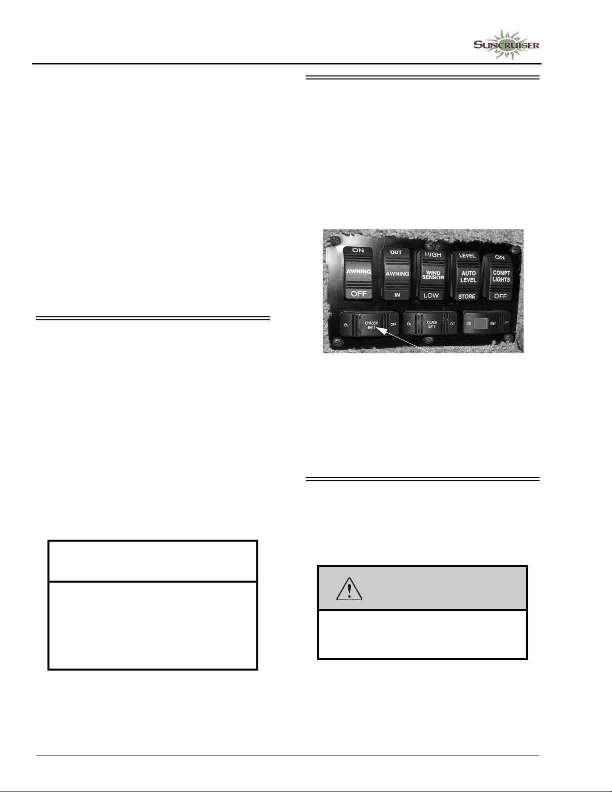
SECTION 3 –
DRIVING YOUR MOTOR HOME
NOTE: On some models the beverage tray (if
equipped) may need to be removed to
provide additional clearance to extract
the engine cover.
If the beverage tray has a drawer, it must
be removed to expose the fasteners that
hold the tray to the motor cover.
• To reinstall the engine cover, position the
front end of the cover first, then lower the rear
end. It is important to be sure the front edge is
pushed completely forward to the radiator
cover to ensure an air-tight seal.
• Press the rear end of the cover down and turn
the hex wrench to the right (clockwise) until
the latch pulls the cover downward and stops.
• Reinstall the two side screws (if equipped).
CHASSIS BATTERY DISCONNECT SWITCH
The Chassis Battery Disconnect switch
disconnects most chassis electrical loads from
the chassis (starting) batteries to avoid discharge
by constant draws such as engine computers,
radio clock, sensors, etc. (except the electric
entrance step). This feature is intended to help
conserve battery charge during storage.
ENGINE COOLING SYSTEM
Do not remove the radiator cap while engine
and radiator are still hot. Always check coolant
level visually at the see-through coolant
reservoir.
NOTE: Your chassis engine cooling system is
filled with special extended-life coolant
that is not the same as common antifreeze available at retail outlets.
The coolant system MUST be refilled or
topped up with the same type of coolant
as equipped to maintain the special longlife properties.
NOTICE
When refilling the coolant system of a
vehicle equipped with a rear auxiliary
automotive heater and motoraid water
heater, be sure to allow for additional
coolant capacity of the heater and its
supply and return hoses.
Chassis Battery Disconnect Switch
(Located near entrance door)
-Typical View
Turn the switch to the OFF or ON positions to
disconnect or reconnect the chassis batteries.
NOTE: The Chassis Battery Disconnect switch
must be on to start the engine.
TIRES
Improper tire pressure can result in tire
overloading and abnormal wear and also affects
handling, ride characteristics, and fuel economy.
WARNING
Make sure all replacement tires are of the
same size and rating as those shown on
your Vehicle Certification Label.
Further Information
Refer to the chassis manual in your InfoCase
for information and precautions on filling,
servicing, and checking the fluid level.
3-14
Page 39
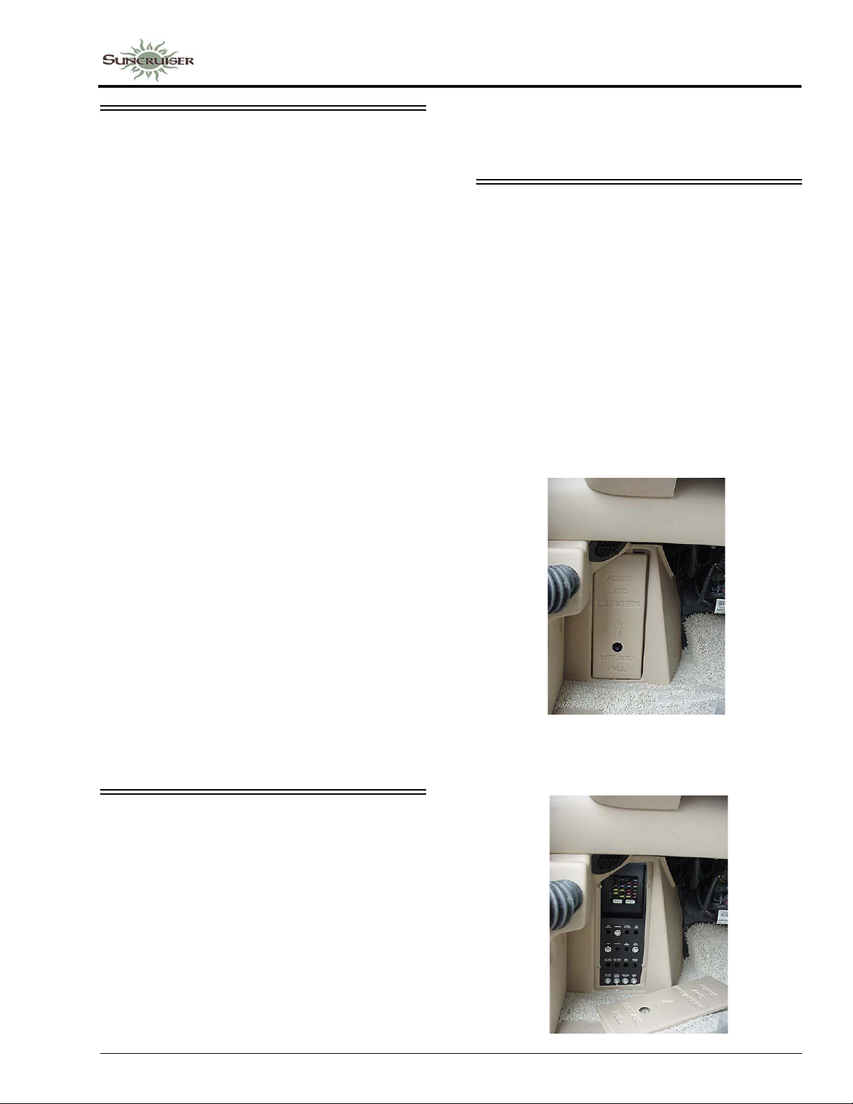
SUSPENSION ALIGNMENT AND TIRE BALANCE
The front suspension and steering system of
this vehicle was factory aligned using highly
accurate equipment prior to delivery to the
dealership. However, alignment should be
checked and adjusted after you have fully loaded
the motor home according to your personal
needs. Thereafter, the alignment should be
periodically inspected to help prevent uneven tire
wear.
Any excessive or abnormal tire wear may
indicate worn or misaligned suspension or
steering, unbalanced tire, or other tire/suspension
problem.
Alignment can be affected by worn steering/
suspension parts or by incidents which happen
during driving, such as hitting a curb, pothole, or
railroad track, etc. Improper alignment can cause
tires to roll at an angle and wear unevenly. It may
also cause the vehicle to “pull” to the right or left.
Have your dealer inspect your vehicle’s
suspension and steering components periodically
for misalignment or wear.
Out-of-balance tires will not roll smoothly and
can lead to vibrations and uneven tread wear,
such as cupping and flat spots. Tires may need to
be balanced if uneven wear is detected or if ride
comfort decreases noticeably.
SECTION 3 –
DRIVING YOUR MOTOR HOME
Further Information
Refer to the chassis manual in your InfoCase
for further information.
CIRCUIT BREAKERS AND FUSES – CHASSIS/DASH AUTOMOTIVE 12-VOLT
The 12-volt automotive fuses and breakers are
conveniently located behind the panel beneath
the left end of the dash in front of the driver’s
seat.
The circuit breakers will pop outward if they
are tripped. Simply push in to reset.
Always replace plug-in blade fuses with ones
of the same size and amperage rating/color.
See your chassis manual for further
information about chassis supplied fuses.
Further Information
See the chassis manual in your InfoCase for
further information.
LIGHTS
All exterior lights should be checked for
proper operation each time the vehicle is
prepared for a trip. Any bulbs which fail to light
should be checked and replaced, when necessary,
with a new bulb of the same size. A failure of
more than one light, such as both taillights not
operating, may indicate a burned out fuse. Check
fuse and replace with one of the same rating
when necessary. If a fuse is not the cause of the
problem, the wiring system should be checked
immediately by an authorized service center.
Automotive Fuse/Breaker Panel
(Located beneath left end of dash)
3-15
Page 40

Page 41
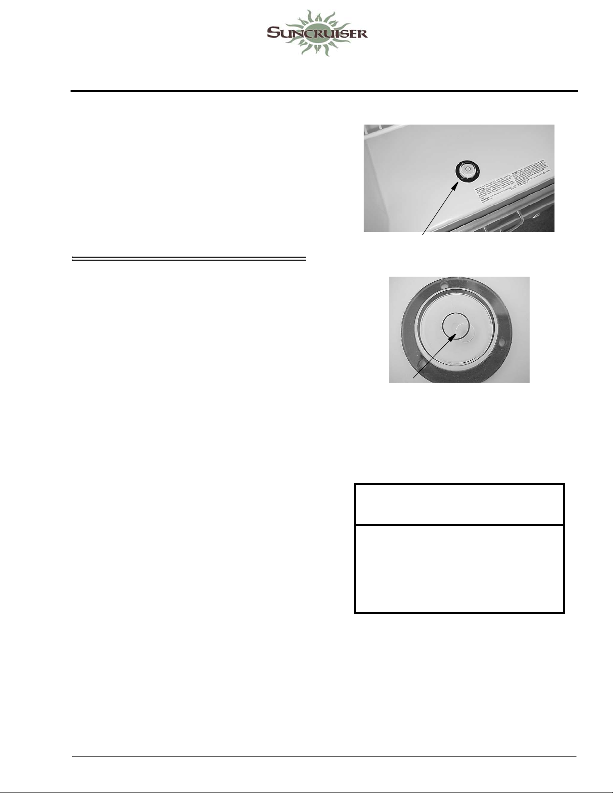
SECTION 4 – APPLIANCES AND SYSTEMS
The appliances installed in your motor home
are manufactured by reputable RV appliance
makers and have been tested by independent
laboratories to meet all applicable standards and
codes set for RV appliances.
See Section 2 - Safety and Precautions of this
manual for any safety and precautions you need
to take regarding the operation of your
appliances.
REFRIGERATOR
The refrigerator in your coach can operate
from either of two energy sources available to the
motor home:
• 120-Volt AC Electric
• Propane Gas
Place bubble level in bottom of refrigerator
To be able to use both types of energy, the
refrigerator does not have a compressor like
household refrigerators. Instead, it uses an
ammonia-water solution for cooling. Basically,
ammonia vapor is distilled from the solution by
heat produced from either propane gas flame or
electrical heat element. The ammonia vapor is
then carried to the finned condenser where it
liquefies. The liquid then flows to an evaporator
where it creates cooling by evaporation. The
ammonia circulates back into the water solution
and the cooling cycle continues.
Leveling
Before operating the refrigerator when the
motor home is stationary, place a small level on
the bottom of the refrigerator and make certain
the unit is level. If over 1/2 of the bubble is inside
the circle in any direction, the coach is level
enough for continuous operation of the
refrigerator while parked.
Bubble must be at least 1/2 inside circle
Normal vehicle leveling to provide comfort
for the occupants is satisfactory for refrigerator
operation.
NOTICE
To prevent permanent damage to the
refrigerator cooling unit, turn the
refrigerator off if the vehicle will be p arked
on an incline of over 3° side-to-side or 6°
front-to-rear (such as steep driveways or
parking lots, etc.) for more than one hour.
Basic Operation
• Press the ON/OFF button to start the
refrigerator.
5 - DASH / AUTO
• If the display code reads “no” there is no
electricity or gas available to operate the
refrigerator. Open the propane tank valve or
connect the shoreline.
4-1
Page 42
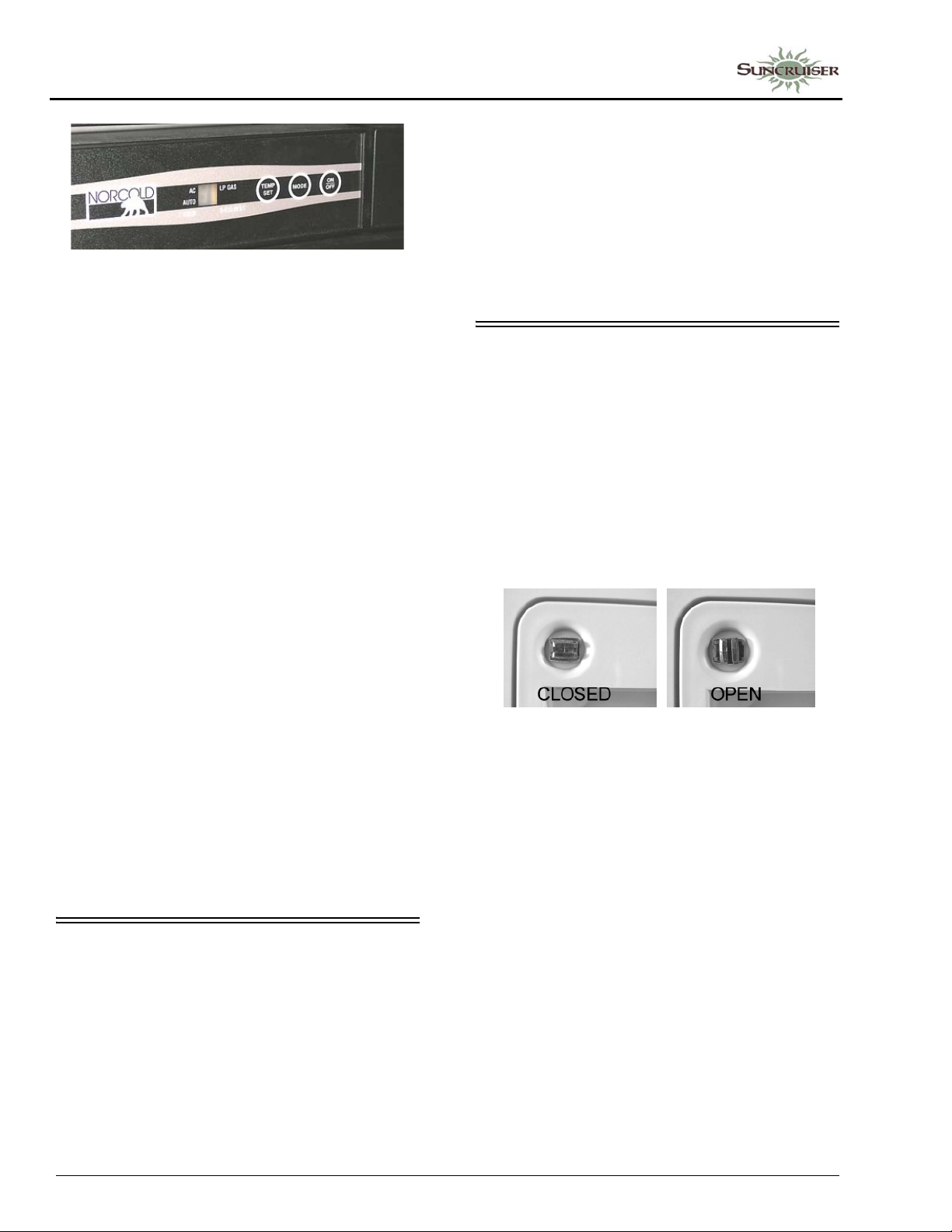
SECTION 4 –
APPLIANCES AND SYSTEMS
• Press the MODE button to select energy
source. There are three settings:
LP (Gas Mode) - Refrigerator will operate on
gas from the propane tank if the main valve is
open and the tank contains gas.
AC (Electric Mode) - Refrigerator will
operate on 120-VAC household current if the
shoreline is connected or the auxiliary
generator is running.
AU (Automatic Mode) - Refrigerator will
automatically start operating on 120-VAC
household current if the shoreline is
connected or the auxiliary generator is
running. If electricity is lost, it will
automatically switch over to LP gas operation
if gas is available.
NOTE: A water shut-off valve for the ice maker
is located near the water faucet filter
inside the galley cabinet beneath the
sink.
Further Information
See the refrigerator manufacturer’s operation,
care and maintenance information in your
InfoCase.
REFRIGERATOR SERVICE ACCESS COMPARTMENT
(Exterior)
The exterior refrigerator service compartment
allows access to the rear of the refrigerator for
inspection, maintenance and service.
To Open
1. Use a screwdriver or coin to turn the latch
knobs to the vertical position as shown.
• Press the TEMP SET button to change
temperature setting from 1 to 9 on display.
Start at the ‘coldest’ setting to ensure coldest
temperature in the freezer compartment, then
adjust warmer as necessary after cold* food
has been added. *The refrigerator will r etain
temperature mor e efficiently if food is already
cold before placing inside.
Further Information
For further information and operating
cautions, see the refrigerator operating
instructions included in your InfoCase.
ICE MAKER
–If Equipped
Some refrigerators are equipped with an
automatic ice maker system. The ice maker unit
is installed in the freezer compartment of the
refrigerator.
Refrigerator Access Door Latches
2. Remove the door from the opening.
To Close
1. Replace the door into the opening.
2. Push the latch knobs in while turning to the horizontal position as shown.
4-2
Page 43
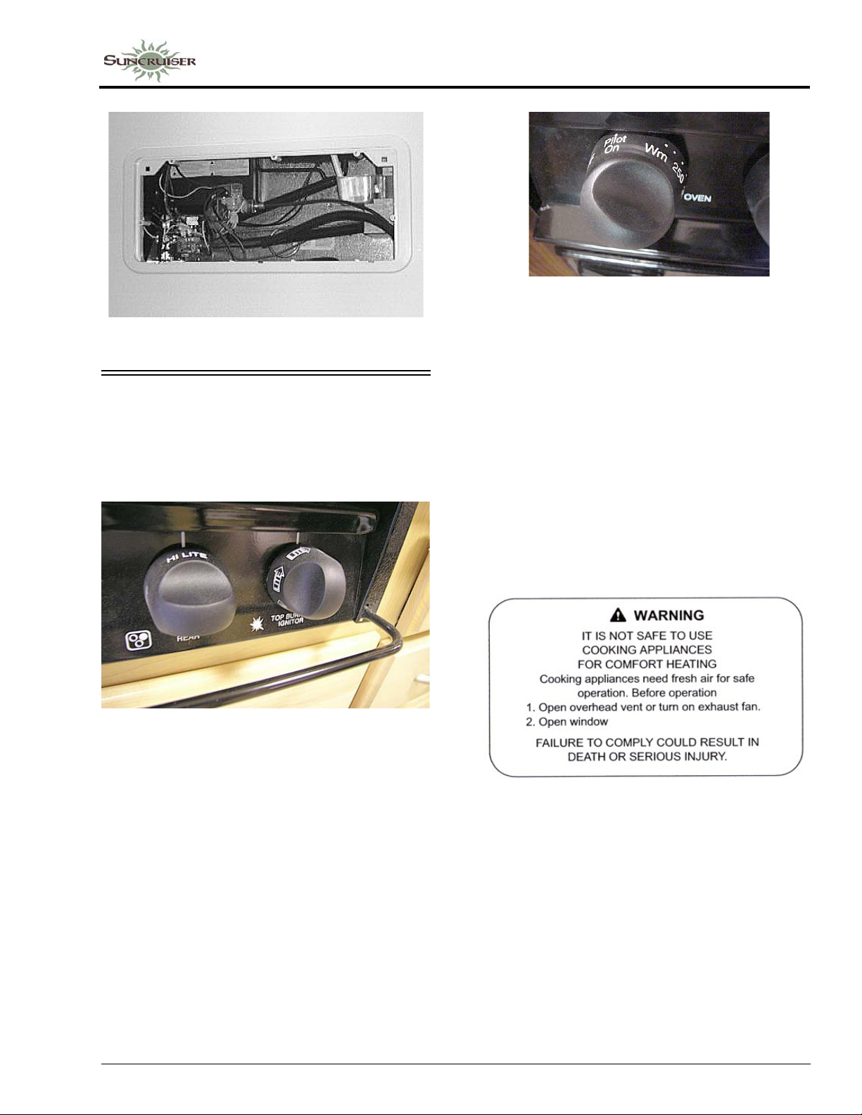
Refrigerator Access Compartment
RANGE AND OVEN
–If Equipped
The range and optional oven in your motor
home operate on propane gas and will provide
most of the functions of the range in your home.
SECTION 4 –
APPLIANCES AND SYSTEMS
Oven Burner Knob
–If Equipped
• Pilot On position keeps pilot flame lit for repeated
use of oven while vehicle is parked
• Turn oven knob to Pilot Off position while
traveling or refilling propane gas tank
To Light Oven Pilot
•See USING THE OVEN in the manufacturer’s
RV Cooking Appliance Use and Care guide in
your InfoCase
To Light Range Top Burners
• Turn the desired burner knob to HI LITE position
• Immediately spin the IGNITOR knob clockwise
at least one full turn to light the burner
If equipped with an oven, the oven knob has a
“Pilot Off” position to turn the oven pilot off
when traveling or refilling the propane tank.
Avoiding Asphyxiation
The following warning label has been located
in the cooking area to remind you to provide an
adequate supply of fresh air for combustion.
Unlike homes, the amount of oxygen supply is
limited due to the size of the recreational vehicle,
and proper ventilation when using the cooking
appliances avoids dangers of asphyxiation.
It is especially important that cooking
appliances not be used for comfort heating, as the
danger of asphyxiation is greater when the
appliance is used for long periods of time.
FAILURE TO COMPLY COULD RESULT
IN DEATH OR SERIOUS INJURY.
4-3
Page 44
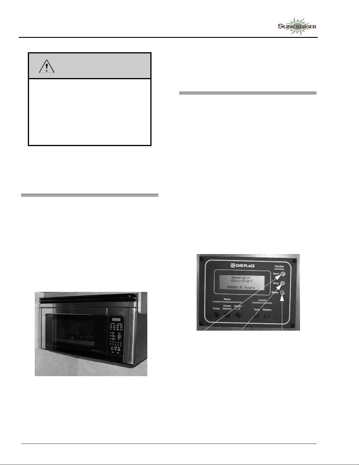
SECTION 4 –
APPLIANCES AND SYSTEMS
WARNING
Portable fuel-burning equipment
including wood and charcoal grills and
stoves, shall not be used inside the
recreational vehicle. The use of this
equipment inside the recreational vehicle
can cause fires or asphyxiation. Failure to
comply could result in death or serious
injury.
Further Information
See the appliance manufacturer’s operation
manual in your InfoCase for complete features
and operating instructions.
MICROWAVE OVEN/RANGE HOOD
-If Equipped
The range hood vent is built into the
microwave oven. The range hood fan carries
cooking odors and gas fumes to the outside of the
coach. A light on the underside of the hood
provides illumination for food preparation. The
hood fan and light switches are located on the
microwave control panel.
Further Information
See the manufacturer’s information in your
InfoCase for microwave operating instructions
and replacement of vent hood light bulbs and
replacement or cleaning of grease filter elements.
ONEPLACE® SYSTEMS MONITOR PANEL
The OnePlace Systems Monitor Panel
provides a convenient, central location for
checking the condition of all utility systems in
your coach.
At the touch of a button, the monitor panel
will display the fresh water and holding tank
levels, propane gas tank level, plus the chassis
battery and house battery condition. You can start
the generator and check the generator hourmeter
or turn on the water pump and water heater.
Generator Start/Stop Switches and Hourmeter
See Section 6 - Electrical for generator startup/shut-down and generator hourmeter
instructions.
4-4
Microwave Oven/Range Hood
(Brand, model, and appearance
shown may vary from your model)
-Typical View
Gen Start Gen Stop Gen
Hourmeter
T ypical - Your coach may or may not be
equipped with all of the features shown.
Water And Holding Tank Levels
Press the Tank Levels switch to show
approximate levels on the LCD screen.
Page 45
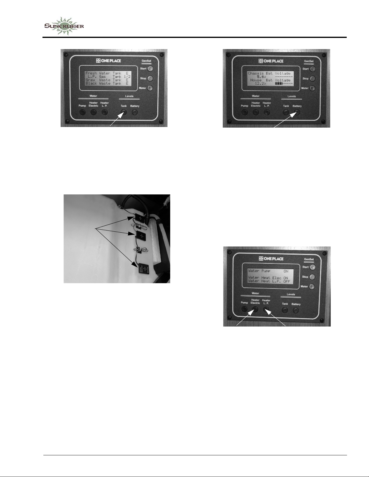
SECTION 4 –
APPLIANCES AND SYSTEMS
Tank Levels Switch
The approximate fluid levels are measured by
electronic sensors on the sides of the tanks. Tank
levels are displayed as 1/3, 2/3, and Full (F).
There is generally more fluid in a tank than
indicated on the monitor panel.
Sensors
Water Tank
-Typical View
Battery Levels Switch
To get an accurate reading:
• Both the chassis engine and the generator
engine must be shut off and 120-volt AC
shoreline unplugged.
• An interior light should be turned on to
provide a small load which draws off the
battery surface charge.
Water Heater Switches
See Water Heater information elsewhere in
this section for operating instructions.
Tank Capacities
See “Tank Capacities” in Section 1 -
Introduction.
Propane Gas Level
Press the Tank Levels switch to show
approximate propane tank level.
The propane level is registered by a sending
unit on the tank. The gauge mounted on the side
of the tank will give a more accurate indication of
actual tank level if needed.
Battery Charge Meter
Press the Battery Levels switch to check the
level of charge (voltage) in the chassis and house
batteries.
Electric
Water Heater
Switch
LP Gas
Water Heater
Switch
Water Pump Switch
When use of the self-contained water system
is desired, press the Pump switch (press once to
get to the desired screen, and a second time to
activate or deactivate.) Water will be available as
soon as a faucet is opened.
4-5
Page 46
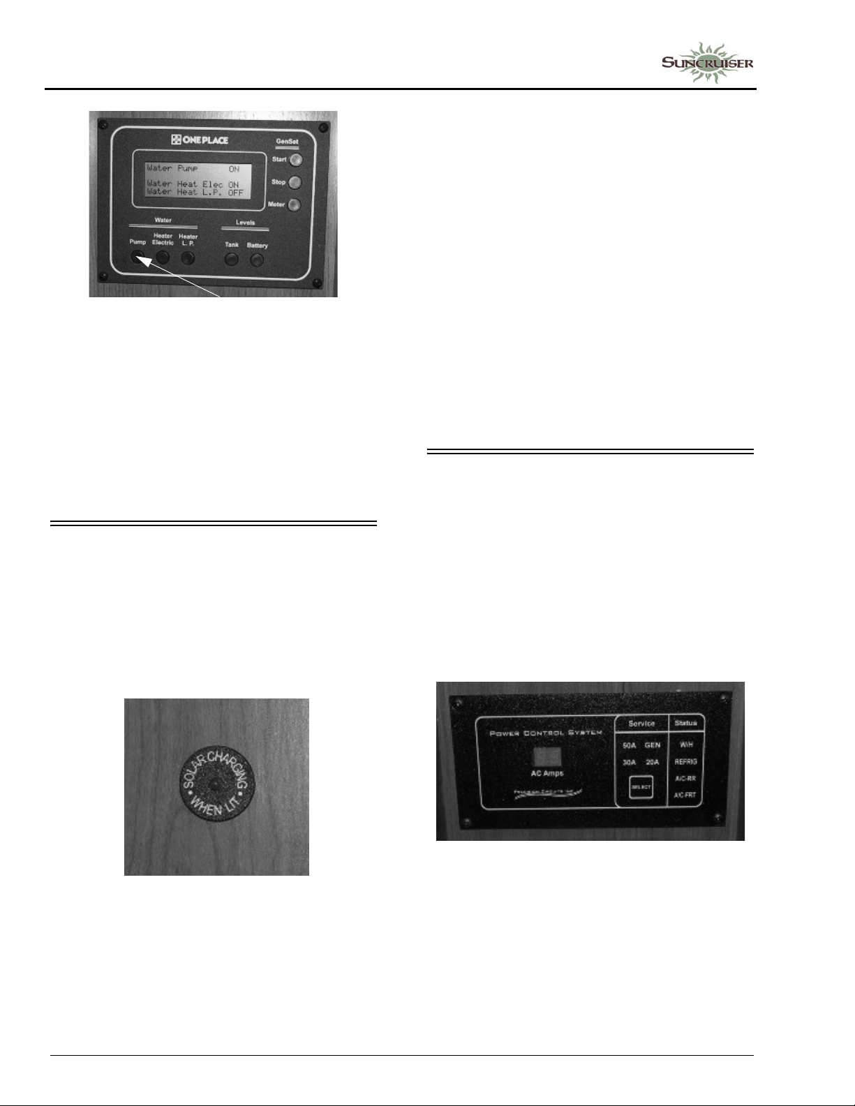
SECTION 4 –
APPLIANCES AND SYSTEMS
Water Pump Switch
Refer to Section 7 - Plumbing for additional
information on the water pump and initial startup.
NOTE: Some models may be equipped with a
Water Pump switch in the water service
center on the outside of the coach or
within the bathroom area for your
convenience.
SOLAR CHARGER PANEL
–If Equipped
The 10-watt roof-mounted solar charger panel
uses the sun to help keep your house batteries
charged. A charge indicator light is provided near
the monitor panel to show you when the solar
panel is actively charging the house batteries.
NOTE: The solar battery charger is not intended
to make the coach battery system
“maintenance free.” The solar panel will
not completely compensate for
continuous low amperage draw from
components such as the propane gas leak
detector, the clock in the dash radio and
the radio station memory circuitry, for
example.
Although the solar panel system can help
to extend battery life, the coach shoreline
should be plugged in routinely to “top
off” the batteries. We also recommend
following regular battery inspection and
maintenance, especially in cold weather.
See “Battery Care” in Section 6 Electrical.
PO WER CONTROL SYSTEM (PCS)
–If Equipped
The Power Control System (PCS) monitors
the electrical usage of the appliances and
equipment in the coach and allows you to use
certain high energy appliances, such as the
microwave or washer/dryer, without overloading
the shoreline circuit breaker to help prevent
nuisance tripping.
Solar Charging Indicator
(Located near monitor panel)
-Typical View
• Glows when charging
• Full glow means maximum charge rate
• Gradually dims as batteries charge
• Goes off when batteries fully charged
4-6
PCS Display Panel
(Located near monitor panel)
-Typical View
Further Information
Refer to the manufacturer’s user guide
provided in your InfoCase for important
information on how this system operates under
several conditions, whether 20-amp, 30-amp, and
50-amp connections, or generator service.
Page 47
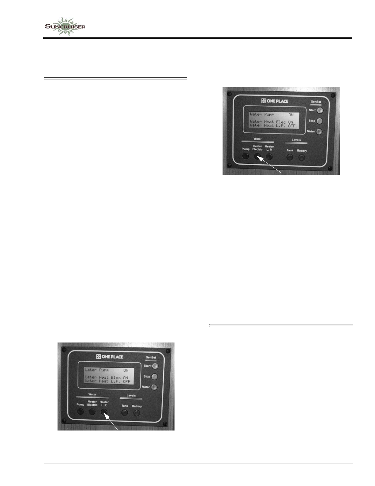
SECTION 4 –
APPLIANCES AND SYSTEMS
NOTE: In 50-amp service, the load meter is
blank. In all other conditions, the load
meter displays actual current load.
WATER HEATER - GAS/ ELECTRIC
The Gas/Electric Water Heater has a dual
power feature. It can operate from propane gas or
120-volt house current, or it can use both at the
same time for quicker recovery at times when
you are using a lot of hot water.
See the Water Heater manufacturer’s
operation manual provided in your InfoCase for
complete operating instructions, safety
warnings, and maintenance information before
operating the Water Heater.
Be sure the Water Heater is filled with
water before starting either electric or
propane gas operation. To fill the Water Heater,
turn the Water Pump switch ON and open a hot
water faucet anywhere in the coach. When water
begins to flow steadily from the faucet, the Water
Heater is full.
For Propane Gas Operation
Press the Water Heater LP switch to ON. The
monitor panel display will indicate that the heater
is “On”. If the monitor panel display reads
“Water Heat LP Fail”, it means that the burner
has gone into “lockout” mode and must be
restarted. If this happens, turn the Water Heater
LP switch off for about 5 minutes, then turn it
back on.
Propane Gas Water Heater Switch
®
(Located on OnePlace
monitor panel)
For Electric Operation
Press the Water Heater Electric switch to ON.
The shoreline must be connected or generator
running for electric operation.
Electric Water Heater Switch
(Located on OnePlace monitor panel)
For Quick Recovery Operation (Dual Heating)
Turn ON both Water Heater switches propane gas and electric. This will help reheat the
Water Heater tank more quickly than a single
source would alone. Use this mode when you are
using a larger than normal volume of hot water.
Further Information
See the Water Heater manufacturer’s
operation manual provided in your InfoCase for
complete operating instructions, safety warnings,
and maintenance information.
MOTORAID WATER HEATER
–If Equipped
The motoraid uses heat from the chassis
engine cooling system to heat water in the water
heater while driving. Hoses are routed from the
engine to a heat exchanger surrounding the water
heater tank.
Under normal conditions, the entire contents
of the water heater can be heated in about two
hours or 100 miles of driving. This means you
can have hot water at the faucets immediately
upon arriving at a site.
The motoraid also increases the capacity of
the engine cooling system.
4-7
Page 48
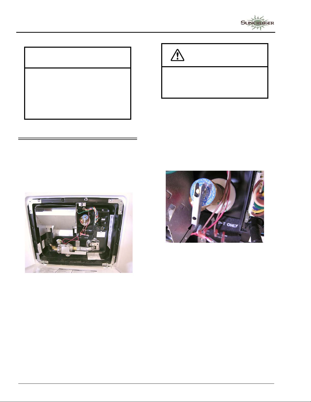
SECTION 4 –
APPLIANCES AND SYSTEMS
NOTICE
Any leak in the heat exchanger or its
supply or return lines could cause loss of
coolant and subsequent engine failure.
We recommend that you periodically
inspect these connecting lines and the
heater to insure that no leaks have
developed.
PRESSURE-TEMPERATURE RELIEF VALVE
On occasion, water may be seen seeping from
the water heater pressure temperature relief
valve. This is no cause for repair or replacement
of the valve.
CAUTION
Hot water can escape from tank causing
injury. Operate this valve only when the
water heater and engine cooling system
are cold.
To Replace the Air Gap:
1. Turn off the Water Heater switch and incoming water supply (city water and/or demand pump).
2. Open a faucet in the motor home to relieve water pressure.
3. Pull the handle of the P-T valve straight out and allow water to flow until it stops.
Water Heater Exterior Service Access
Normally there is an air gap at the top of the
water heater tank, which acts as a pressure buffer.
In time, however, heated water may expand and
fill this air gap, causing a slight increase in water
pressure. This may cause the P-T valve to “weep”
until the air gap is manually replaced.
4-8
• Lift handle straight out to open P-T valve
when water heater is cold
4. Let the handle of the P-T valve snap shut.
5. Close the faucet and turn on the water supply before switching the water heater on.
Manually operate the pressure temperature
relief valve at least once a year.
NOTE: If your water heater is equipped with the
motoraid system, it uses an extension
from the engine cooling system to heat
water in the water heater while driving.
The engine cooling system must also be
cold before opening the pressuretemperature relief valve. See “Motoraid
Water Heater” for more information.
Page 49
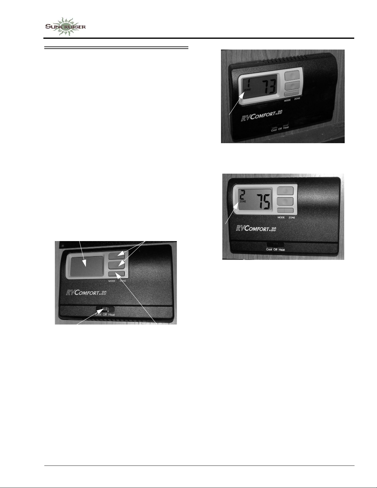
ELECTRONIC THERMOSTAT
(Heating and Cooling)
The Thermostat (located near the monitor
panel) controls the propane furnace, as well as
the two separate roof air conditioners in your
coach. The living area and galley are equipped
with one air conditioner, and the bedroom and
bath area are equipped with another.
When controlling the settings from the
Thermostat, you must manually press the “Zone”
side of the Mode/Zone button and set to your
preference by toggling to either Zone 1, Zone 2,
or both.
• ZONE 1 - Living/Galley Area
• ZONE 2 - Bedroom/Bath Area
The Thermostat system will operate in both
heat and cool modes, but will not allow you to
run both heat and cool modes simultaneously.
SECTION 4 –
APPLIANCES AND SYSTEMS
Zone 1 Operation
(Living Area/Galley)
LCD Display Screen
Thermostat Switch
COOL = Air Conditioning
HEAT = Furnace
Electronic Thermostat
(Located near monitor panel)
-Typical View
Setpoint Buttons
Mode/Zone
Button
Zone 2 Operation
(Bedroom/Bath)
NOTE: The Thermostat does not automatically
switch between heating and cooling. You
must place the Thermostat switch in the
desired position.
Heating
1. Open the LP gas tank valve by turning fully counter-clockwise.
2. Select Zone.
3. Slide the Thermostat switch to the “Heat” position.
4. Press the “Mode” side of the Mode/Zone button and toggle between settings to select either “Gas Heat” (for Propane Furnace) or “Heat Elec” (for Heat Pump).
5. Adjust the temperature setpoint to personal preference if needed. See “Changing Temperature Setpoints.”
4-9
Page 50

SECTION 4 –
APPLIANCES AND SYSTEMS
Cooling (A/C)
1. Select Zone.
2. Slide the Thermostat switch to Cool position.
3. Press the “Mode” side of the Mode/Zone button and toggle to your desired setting:
• Cool/Auto: Allows the fan speed to vary
depending on the cooling needs. This is the
default setting.
• Cool High/Cool Low: Sets the fan speed to
run continuously at high or low , but the upper
unit will cycle when cooling is needed.
• Fan High/Fan Low: Sets the fan to run
continuously at high or low speed. The upper
cooling unit will not run to produce cooling.
Setpoint is not adjustable in this mode.
• Off: Turns the upper unit off for the zone
displayed. By continuing to press the “Mode”
button, you can toggle through the settings for
the zone displayed until you have reached
your desired setting. Setpoint is not adjustable
in this mode.
4. Adjust the temperature setpoint to personal preference if needed. See “Changing Temperature Setpoints”.
5. Once you have established the settings for Zone 1, press the Zone button to store settings in Thermostat memory.
NOTE: Repeat steps for each zone.
Heat Pump
Your coach is equipped with an air source
Heat Pump built into the air conditioning system.
Because the Heat Pump operates on electricity, it
provides economical heat inside your coach and
helps reduce the use of propane gas for heating in
cooler weather.
A Heat Pump can be thought of as an air
conditioner running in reverse. An air
conditioner absorbs heat from the air on the
inside of the coach and moves it to the outside.
The Heat Pump does exactly the opposite. Even
cold air contains some heat, so a Heat Pump will
extract heat from the outside air on a cold day and
carry it to the inside of the coach to maintain a
comfortable temperature.
The efficiency of a Heat Pump decreases as
the outdoor air temperature drops, so
supplementary heat is often needed when the
outside temperature nears freezing. This system
is set to automatically start the propane furnace to
assist the Heat Pump if room temperature cools to
5 degrees or more below the Thermostat set
temperature. You may wish to manually switch
to propane furnace heat to maintain a higher
temperature when outside temperatures begin to
reduce the efficiency of the Heat Pump. The Heat
Pump will not operate when the outside
temperature falls below 36 degrees F.
To Run Fan Only (No Heat or Air)
1. Set Thermostat switch to COOL.
2. Press the “Mode” side of the Mode/Zone
button.
3. Toggle between settings and select FAN
HIGH/FAN LOW.
4. The fan will run continuously at the selected
speed and is not controlled by Thermostat
setting. The display will show current room
temperature.
LCD Thermostat Display
The LCD Display Screen displays a variety of
features, including the room temperature and
setpoint temperature. If the word “Set” is shown
above the temperature, then the setpoint or
desired temperature is shown. If the word “Set” is
not shown, then the temperature shown is the
actual room temperature.
Changing Temperature Setpoints
To change the temperature, press the up or
down arrow once on the Setpoint button. The
word “Set” will appear on the display screen.
This puts the system in the mode to change the
setpoint temperature. Then, press the up or down
arrow until your have reached your desired
temperature.
NOTE: The temperature setpoint cannot be
adjusted in the following situations:
When the Thermostat switch is set to
OFF, when the zone is turned off for
4-10
Page 51
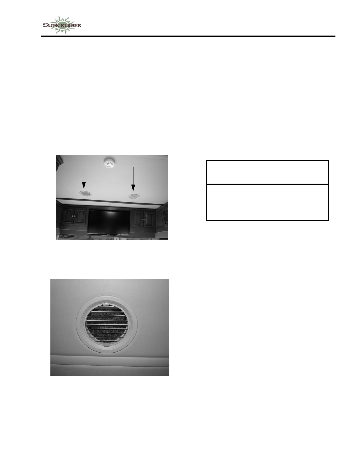
SECTION 4 –
APPLIANCES AND SYSTEMS
either heating or cooling mode, or when
the fan is set to be running continuously
in either high or low speed.
Supply and Return Air Vents
Supply and Return Air Vents are located
throughout the ceiling of the coach. The Supply
Vents produce airflow. The Return Vents are for
air intake, in which the air goes back into the air
handler. There is a distinguishable difference
between the two - Return Air Vents are equipped
with a removable filter inside, and Supply Air
Vents are not.
Condensate Drain Lines
The two roof air conditioners are equipped
with condensate water pumps, which allows
water that is extracted from the roof air
conditioners to be pumped through two separate
drain lines (located at the rear of coach).
If you notice water running off of the roof
when the air conditioners are running, this is a
sign that one or more of the drain lines have
plugged and water is now flowing out of the
safety overflow of the air conditioner(s). See
your Winnebago Industries® dealer for service
and proper cleaning of the drain lines.
NOTICE
Water running off the roof is a sign the
condensate drain lines are plugged and
require service. Failure to comply may
result in water damage to the roof.
Supply/Return Air Vents
(Located throughout the ceiling of the coach)
-Typical View
Return Air Vent
(Shown with filter installed)
Further Information
For complete operating instructions and
troubleshooting procedures, see the
manufacturer’s user guide provided in your
InfoCase.
4-11
Page 52
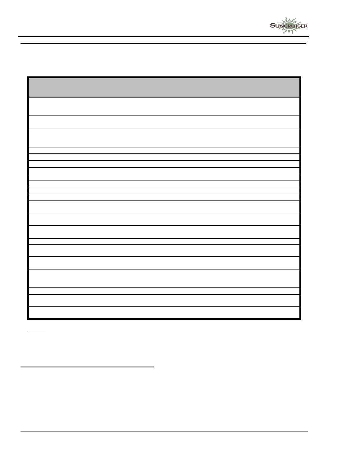
SECTION 4 –
APPLIANCES AND SYSTEMS
ELECTRONIC THERMOSTAT OPERATION CHART
The following chart shows the system functions with the Electronic Thermostat (Heating and Cooling)
CONTROL
SLIDE
SWITCH
Off N/A 1-4 N/A N/A
Cool Cool Auto 1-4 No N/A
Cool Cool Auto 1-4 Yes N/A
Cool Cool High 1-4 No N/A
Cool Cool High 1-4 Yes N/A
Cool Cool Low 1-4 No N/A Fan Low is energized.
Cool Cool Low 1-4 Yes N/A
Cool Fan High 1-4 N/A N/A
Cool Fan Low 1-4 N/A N/A
Cool Off 1-4 N/A N/A
Heat Elec 1-4 No Non-HP
Heat Elec 1-4
Heat Elec 1-4
Heat Elec 1-4
Heat Elec 1-4 No HP
Heat Elec 1-4
Heat Elec 1-4
MODE ZONE DEMAND
Stage 1 (1 degree
below setpoint)
Stage 2 (5 degrees
below setpoint)
Stage 3 (7 degrees
below setpoint)
Stage 1 (1 degree
below setpoint)
Stage 2 (5 degrees
below setpoint)
BOX - H/P
JUMPER
Non-HP
Non-HP
Non-HP
HP
HP
OPERATION OF UNIT
No units operating in this mode. LCD is displaying temperature of Zone.
User can toggle through zones to see temperature in each zone
(setpoint cannot be adjusted).
Nothing is operating since there is no cooling demand. LCD is displaying
temperature of Zone.
Compressor is energized. If 1 degree above setpoint, then fan Low is
energized; If 2 degrees above setpoint, then fan High is energized and
locks in on High.
Fan High is energized.
Compressor is energized/fan High is energized.
Compressor is energized/fan Low is energized.
Fan High is energized (setpoint cannot be adjusted).
Fan Low is energized (setpoint cannot be adjusted).
Nothing operational in Zone (setpoint cannot be adjusted).
Nothing is operating in this mode since there is no heating demand.
Fan Low is energized. Heat strip is energized.
Fan Low is energized. Heat strip is energized. Low gas heat energized
(Zones 1 and 2 only). See Notes 1 and 2.
Fan Low is energized. Heat strip is energized. Low and High gas heat
energized (Zones 1 and 2 only). See Notes 1 and 2.
Nothing is operating in this mode since there is no heating demand.
High Fan energized. Compressor and reversing valve energized.
High Fan energized. Compressor and reversing valve energized. Low
Gas Heat energized (Zones 1 and 2 only). See Notes 1 and 2.
Stage 3 (7 degrees
Heat Elec 1-4
Heat Gas 1-2 No N/A
Heat Gas 1-2
Heat Gas 1-2
NOTES:
1) When 2nd or 3rd stage heating is activated, it stays on until setpoint is satisfied. When heating stage is running for more than 20
minutes without reaching setpoint, then the next available heating stage will be energized.
2) The word "Gas" will display on the LCD screen when 2nd stage heat (Low Gas Furnace) is operating.
below setpoint)
Stage 1 (1 degree
below setpoint)
Stage 2 (5 degrees
below setpoint)
High Fan energized. Compressor and reversing valve energized. Low
and High Gas Heat energized (Zones 1 and 2 only). See Notes 1 and 2.
HP
Nothing is operating in this mode since there is no heating demand.
N/A Low Gas Heat energized.
Low Gas Heat energized. High Gas Heat energized. See Note 1.
N/A
AIR CONDITIONER FILTERS
Air conditioner filters are located inside the
Return Air Vents throughout the ceiling of the
coach and must be inspected monthly and
cleaned periodically so the air conditioners will
operate efficiently.
4-12
Page 53
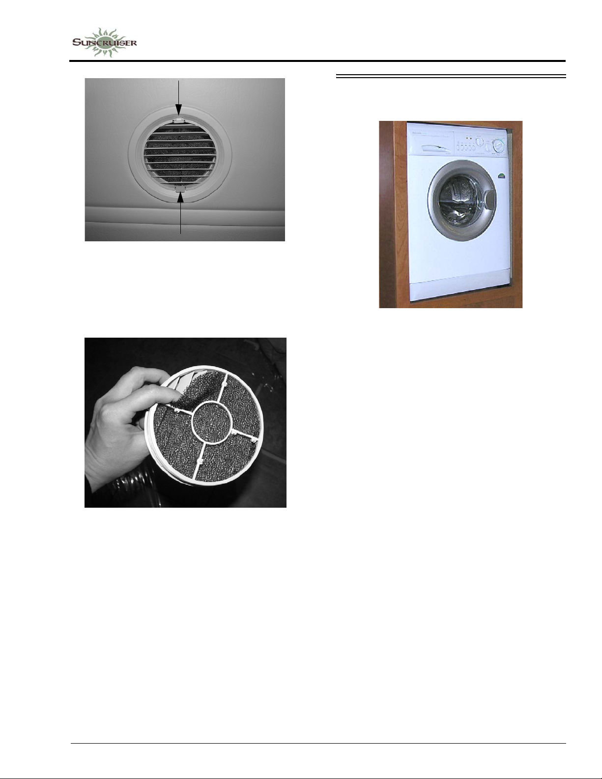
Return Air Vent
(Press tabs inward to remove air vent)
It is recommended to use mild soap and warm
water to clean the air filters. When finished,
allow filters to air dry.
SECTION 4 –
APPLIANCES AND SYSTEMS
WASHER/DRYER
–If Equipped
To Open the Doo r During a Wash Cycle
Follow these steps if you need to open the
door to your washer/dryer after a cycle has
already begun.
Air Filter
(Located on back side of Return Air Vent)
NOTE: There are multiple Supply and Return
Vents throughout the coach. Therefore,
you must remember to remove each
separate air filter from each Return Air
Vent to clean.
1. Advance the Program Selector to “Reset” and
wait 5 seconds.
2. Advance the Program Selector to “Drain” (8
o'clock) and allow the machine to drain
completely.
3. Advance the Program selector to “Reset” (the
“Status/Door Lock” LED will blink quickly to
indicate that the cycle has stopped, but the
door is STILL LOCKED).
4. When the “Status/Door Lock” LED blinks
SLOWLY (takes 1-2 minutes), you can open
the door.
To Open During a Dry Cycle
1. Advance the Program selector to “Reset” (the
“Status/Door Lock” LED will blink quickly to
indicate that the cycle has stopped, but the
door is STILL LOCKED).
2. When the “Status/Door Lock” LED blinks
SLOWLY (takes 1-2 minutes), you can open
the door.
IMPORTANT! Once a wash cycle is
underway, the washer/dryer door will LOCK for
the duration of the cycle and will STAY LOCKED
4-13
Page 54
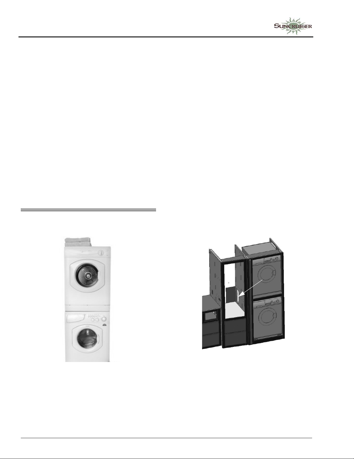
SECTION 4 –
APPLIANCES AND SYSTEMS
for up to 2 minutes after the cycle ends. DO NOT
attempt to open the door unless the “STATUS/
DOOR LOCK” LED is BLINKING SLOWLY!
Water Supply Faucets
The washing machine water supply faucets
are located behind the combination washer/dryer.
Extend (or remove) pantry drawer above washer/
dryer to access.
Always turn supply faucets off when not using
washing machine to avoid possible water leaks if
a hose or hose gasket should fail.
See “Winterizing Optional Appliances” in
Section 7 - Plumbing for steps in winterizing your
washer/dryer.
Further Information
For complete washer/dryer operating
instructions, see the manufacturer’s information
provided in your InfoCase.
WASHER/DRYER - STACKABLE
–If Equipped
3. Rotate the PROGRAMS dial to the desired washing program, or DRAIN.
After the washer drains, wait for the DOOR
LOCK light to extinguish before attempting to
open the door.
The washing machine door will stay locked
for up to two minutes after the program is
completed.
NOTE: Never attempt to open the door when the
DOOR LOCK light is on!
Water Supply Faucets
The washing machine water supply faucets
are located inside the washer/dryer cabinet. Open
the access door located inside the wardrobe
cabinet to access.
NOTE: Slideout room must be extended to reach
the access door.
Always turn supply faucets off when not using
washing machine to avoid possible water leaks if
a hose or hose gasket should fail.
To Reset or Cancel a Wash Cycle
If resetting or canceling a program is
necessary:
1. Rotate the PROGRAMS dial clockwise to a STOP/RESET position.
2. Wait five seconds.
4-14
Water Supply Faucets
(Located in washer/dryer
cabinet behind access door)
-Typical View
See “Winterizing Optional Appliances” in
Plumbing - Section 7 for steps in winterizing your
washer/dryer.
Page 55
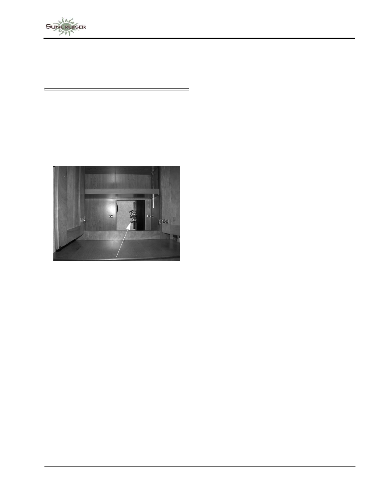
Further Information
For complete washer/dryer operating
instructions, see the manufacturer’s information
provided in your InfoCase.
WASHER/DRYER - PREP PACKAGE
If your coach is not equipped with a washer/
dryer, plumbing may be present for installation.
Typically, the plumbing is located inside the
rear linen cabinet (remove shelving and panels to
access).
SECTION 4 –
APPLIANCES AND SYSTEMS
Water Supply Faucets
-Typical Installation
We recommend obtaining parts and service
for the washer/dryer installation from your
Winnebago® or Itasca® dealer.
4-15
Page 56

Page 57
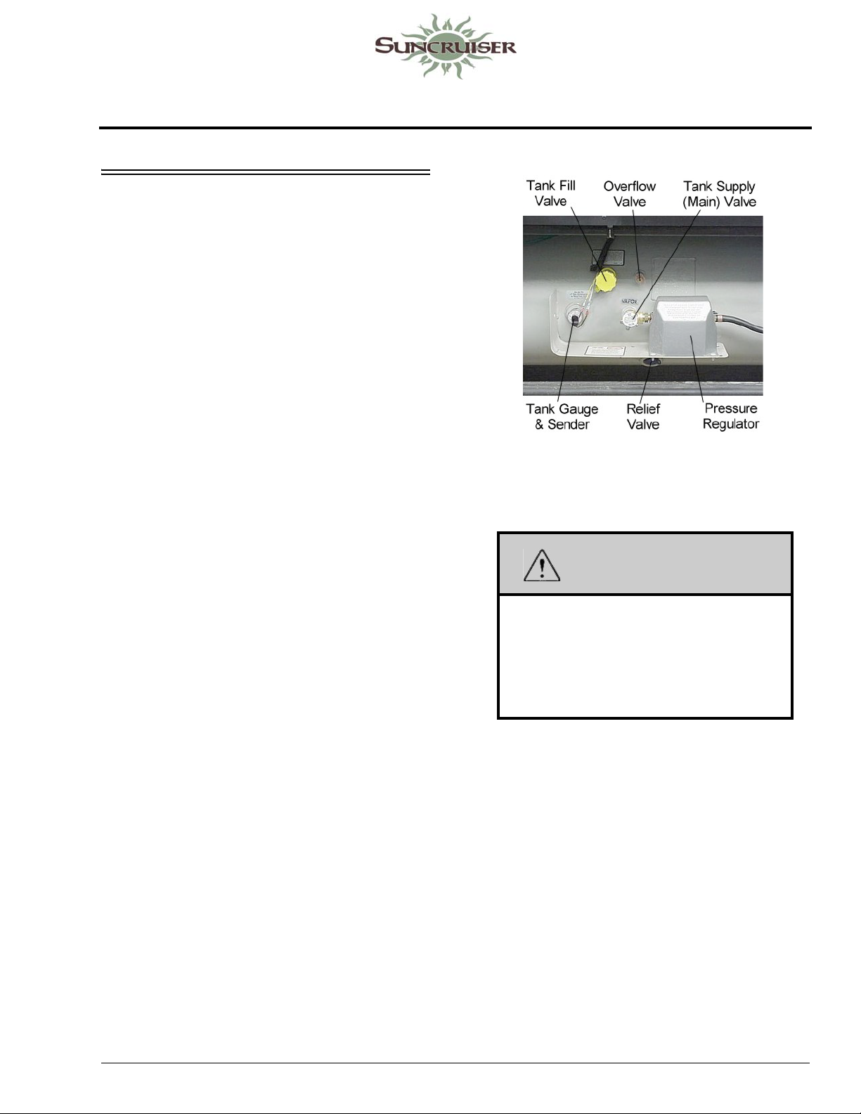
SECTION 5 – PROPANE GAS
PROPANE GAS SUPPLY
The propane gas system supplies fuel for the
gas range/oven, water heater, furnace, and
refrigerator (while in gas mode). When used and
handled properly, this system is safe and
economical and provides modern living
conveniences wherever you travel.
See Section 2 - Safety and Precautions in this
manual for other safety and precautions you need
to be aware of related to propane.
How Propane Gas Works
Propane is a type of LP (Liquefied Petroleum)
gas compressed into liquid form for easy
transportation and storage. Propane gas may also
be called tank gas, bottle gas, or simply LP.
Propane is used by appliances in vapor form
only, but is stored in the tank as a liquid under
very high pressure. As the liquid gas is released,
it reverts back to a vapor and expands to many
times its compressed volume.
Propane Tank System
The storage reservoir for the propane gas
system is a horizontally mounted tank which is
permanently attached to the vehicle frame. The
tank is accessible only from the outside of the
vehicle.
Propane Tank Features
-Typical View
WARNING
Do not alter or remove propane tank
valves or gauge. Propane can escape,
which can cause an explosion resulting in
death or serious injury . Have the propane
system serviced by a qualified service
center.
Refilling Propane Tank
Since the propane tank is permanently
mounted to the frame, the motor home must be
taken to a propane dealership for filling. Do not
attempt to remove the propane tank from the
vehicle. The tank is equipped with a fill adapter
with both internal and external threads, which
allows easy filling with any propane filling
equipment. The tank is full when liquid propane
gas appears at the overflow valve.
5 - DASH / AUTO
NOTE: The propane tank is equipped with an
automatic 80% stop-fill device.
5-1
Page 58
SECTION 5 –
PROPANE GAS
DA NG E R
DO NOT FILL CONTAINER TO MORE
THAN 80 PERCENT OF CAPACITY.
FAILURE T O COMPLY COULD RESUL T
IN A FIRE OR PERSONAL INJURY.
Make sure the motor home is level when
filling. It is possible to accidentally overfill
the tank if the vehicle is not level, with the
fill valve on the uphill side. Overfilling the
propane gas tank can result in
uncontrolled gas flow, which can cause
fire or explosion. A properly filled
container will contain approximately 80
percent of its volume as liquid propane
gas.
All pilot lights must be extinguished
and appliances and their ignitors turned
off, and supply valve closed before
refilling propane gas tanks or vehicle fuel
tanks.
Do not smoke or expose an open flame
while near a propane refueling area.
Propane gas is heavier-than-air and
extremely flammable.
Never fill the propane tank with engine or
generator running.
Before opening the supply valve, check to
be sure all controls for gas appliances are
in the “Off” or “Pilot Off” position. If this
step is not performed, propane gas could
accumulate inside the motor home
creating a fire or explosion hazard.
Never use an open flame to test for
propane gas leaks.
Replace all protective covers and caps on
propane system before filling.
Selecting Propane Fuel Types
We recommend using straight propane in your
propane tank. Propane gas is commonly available
at all propane gas outlets in the U.S. (According
to the National Propane Gas Association,
propane gas outlets in the United States do not
offer any other type of liquefied petroleum gas
than propane to the general public.) Check local
phone directory yellow pages for locations of
local propane gas refilling stations or bulk
dealerships.
NOTE: If you travel outside the U.S. with your
motor home, you may find butane or
propane/butane mixtures available in
addition to propane. Because gasburning RV appliances ar e designed to
run on propane only, we recommend that
you request straight propane only.
Butane burns about 30 percent hotter
than propane and can overheat some
appliances, particularly refrigerators,
and cause permanent damage. Other
appliances designed to operate on
propane can become sooted and lose
efficiency by using butane fuel.
Air in the Propane Gas Tank
If your gas appliances do not stay lit or require
frequent adjustment, even though you know the
propane tank contains sufficient fuel, the
problem may be air in the propane gas tank. Air
in the tank mixes with the propane gas vapors
causing them to burn poorly. This condition
could linger for weeks if the air is not purged
from the tank. Most propane gas dealers have
equipment for purging air from propane gas tanks
and will purge before refilling the tank.
SAFE USE OF THE PROPANE GAS SYSTEM
The propane system is designed and built with
strict adherence to national, state, and
recreational vehicle industry requirements for
mobile propane gas equipment.
For your safety, there are many safety devices
and backup systems installed, such as tank fill
overflow valves, an interior propane gas detector/
alarm, and an interior carbon monoxide (CO)
detector/alarm.
Propane gas also contains an odor additive
that you can smell if propane is present in the air.
Here are a few precautions to observe that will
help you to use the propane gas system safely:
5-2
Page 59
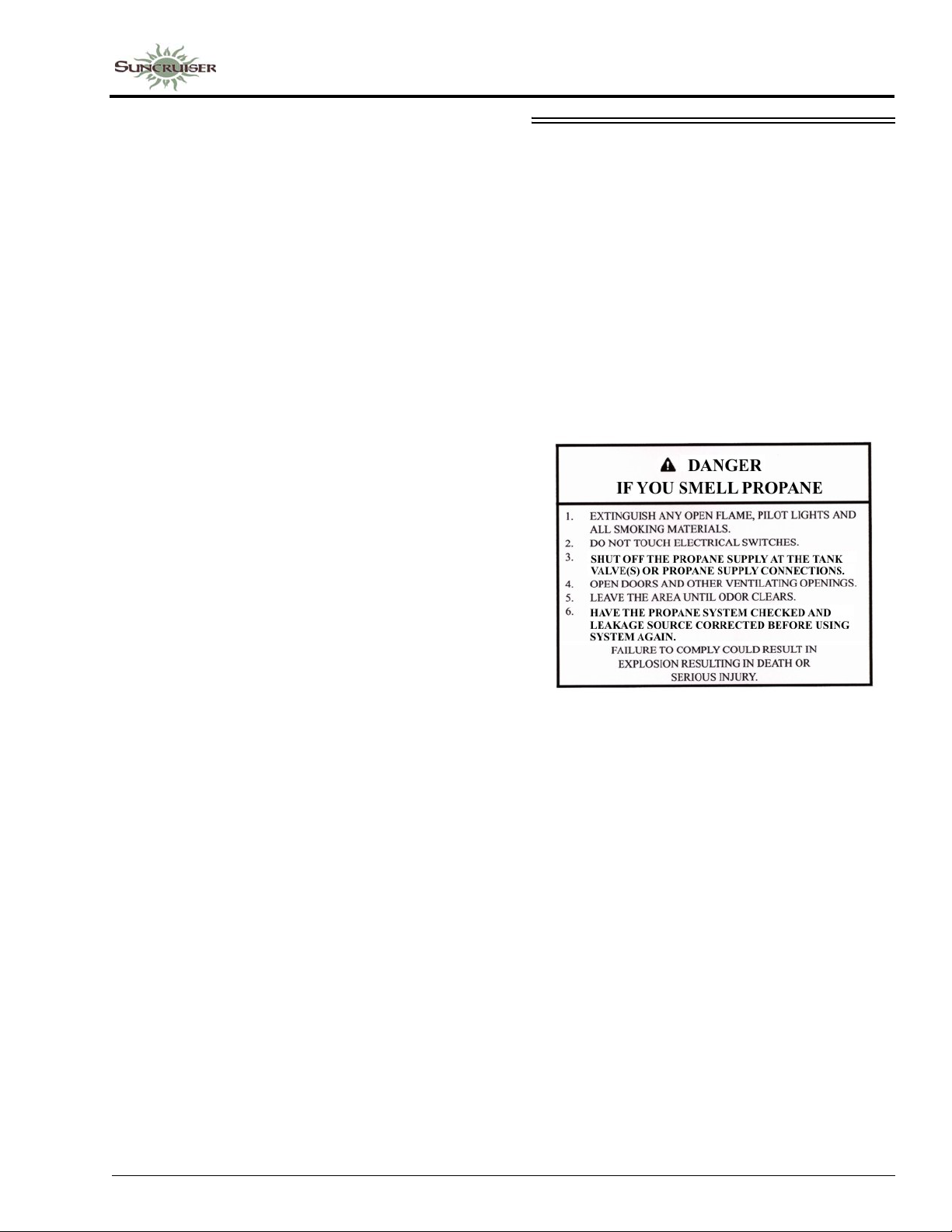
• Exercise caution at all times. Be familiar with
the distinctive odor of propane gas. If a leak is
suspected, turn off the supply valve
immediately. Have the propane gas system
checked by your dealer or other qualified
propane gas service center.
• Do not tamper with the propane gas piping
system, pressure regulator, or gas appliances.
Service and maintenance of propane gas
system components should be performed only
by your dealer or a qualified propane gas
service center.
• Never attempt to connect natural gas to the
propane gas system.
• Have the entire propane gas system inspected
for possible leaks and missing or damaged
parts at each tank filling. Also inspect before
and after each trip, and any time trouble is
suspected.
SECTION 5 –
PROPANE GAS
PROPANE GAS WARNINGS AND PRECAUTIONS
It is illegal for vehicles equipped with propane
tanks to travel on certain roadways or through
certain tunnels in the U.S. To avoid
inconvenience, check state regulations
concerning flammable gas transportation.
Propane Gas Leaks
The following label is located in the vehicle
near the range area. If you smell gas within the
vehicle, quickly and carefully perform the
procedures listed.
• Turn the propane supply valve off when not
using the propane gas system.
• Never use a wrench to tighten the tank supply
valve. It is designed to close leak-tight by
hand. If a wrench is required to completely
close the valve, it is defective and must be
replaced.
• Be sure appliance and outside vents are open
and free from obstruction when using the
propane gas system.
• Never attach a lock or any device requiring a
key to the propane tank compartment door.
According to standards set for recreation
vehicles, the propane supply valve must be
readily accessible in an emergency.
• Exercise caution when drilling holes or
attaching objects to the walls. Gas lines and
electrical wiring could be seriously damaged
and present an extreme safety hazard.
• All pilot lights must be extinguished and
appliances and their ignitors turned off while
refilling the fuel tank or propane tank.
• Never smoke while refilling vehicle fuel tank
or propane gas tank.
• Avoid inhaling exhaust gases produced by
burned gasoline, diesel fuel, or propane gas in
items such as the range, chassis engine,
generator engine, refrigerator, furnace, and
water heater. They contain carbon monoxide,
which is an odorless, colorless, and poisonous
gas.
5-3
Page 60
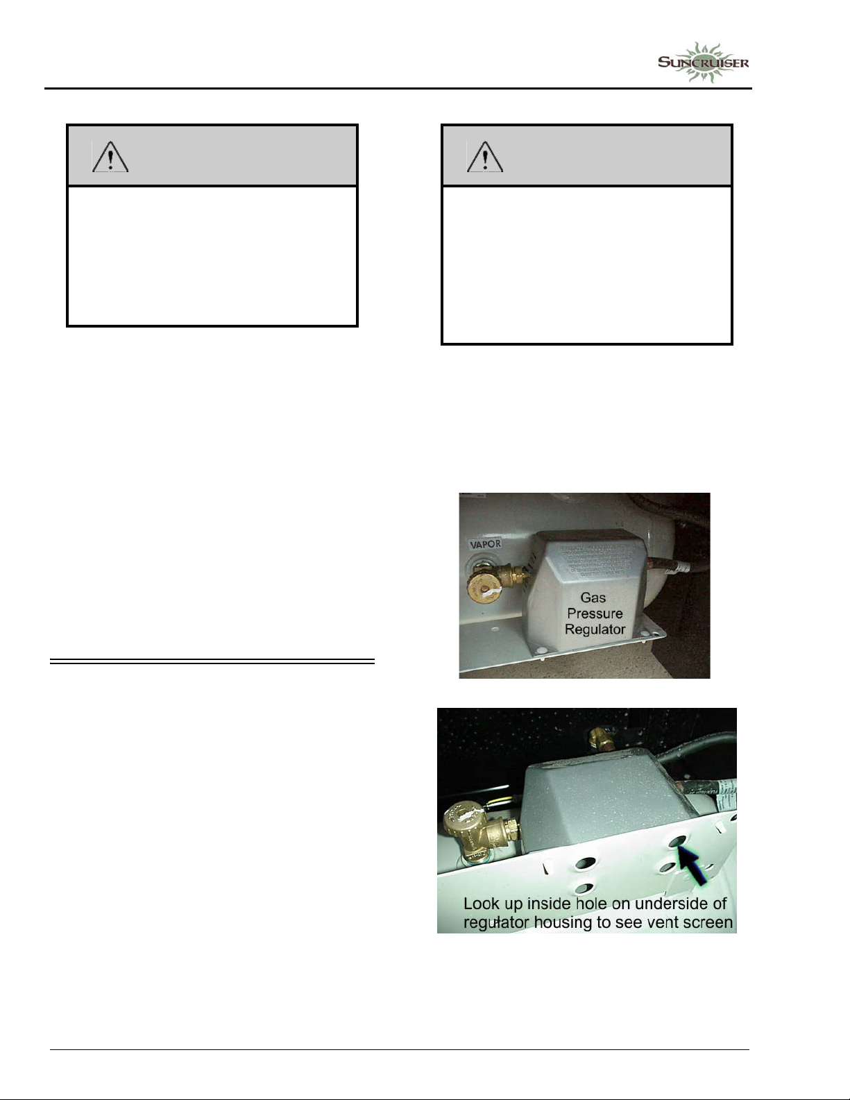
SECTION 5 –
PROPANE GAS
WARNING
Propane cylinders shall not be placed or
stored inside the vehicle. Propane
cylinders are equipped with safety
devices that relieve pressure by
discharging propane to the atmosphere.
Failure to comply could result in death or
serious injury.
• Never use an open flame to test for propane
gas leaks. Replace all protective covers and
caps on propane system after filling. Make
sure valve is closed and door latched securely .
• Portable fuel-burning equipment, including
wood and charcoal grills and stoves, shall not
be used inside the recreational vehicle. The
use of this equipment inside the recreational
vehicle may cause fires or asphyxiation.
• Regulators are equipped with a protective
cover . Make sure that the regulator vent faces
downward and that the cover is kept in place
to minimize vent blockage, which could result
in excessive gas pressure causing fire or
explosion.
WARNING
Visually inspect the pressure regulator
vent periodically for blockage by
accumulated debris or insect nests, etc.
Vent obstruct ion could result in excessive
pressure causing fire or explosion, which
could result in death or serious injury . If an
obstruction exists, have the regulator
serviced by a qualified service center.
NOTE: If your model is equipped with a propane
powered electrical generator, there will
be two regulators stacked one upon
another. One regulates the house
propane supply pressure, the other
regulates pressure to the generator.
PROPANE GAS PRESSURE REGULATOR
The pressure regulator is protected from the
elements by a plastic cover, which should be left
in place at all times.
Propane regulators must always be installed
with the regulator vents facing downward.
Regulators that are not in compartments have
been equipped with a protective cover. Make sure
that the regulator vent faces downward and that
the cover is kept in place to minimize vent
blockage that could result in excessive propane
pressure causing fire or explosion.
Only your dealer or a qualified propane gas
service should remove the regulator cover for
adjustments.
5-4
Page 61
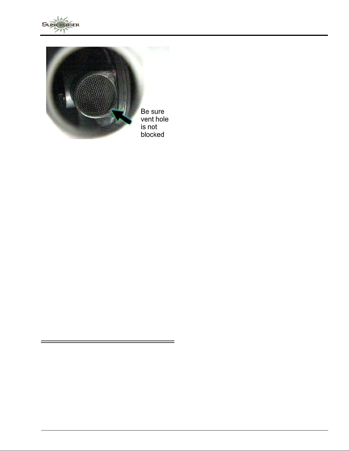
Regulator Freeze-up
Regulator freeze-ups are caused by the
presence of moisture in fuel. This moisture will
pass through the cylinder valve and into the
regulator where it can freeze. Fuel producers,
tank and bottle manufacturers, and propane gas
dealers take every precaution to reduce moisture,
but sometimes only a fraction of an ounce
entering the tank can cause problems. To help
avoid the possibility of freeze-up, always keep
tank control valve closed when not in use, even
when tank is empty, to prevent moisture from
collecting on the inside.
If regulator freeze-up should occur, you may
attempt to thaw the regulator using a light bulb.
DO NOT USE AN OPEN FLAME OR HEAT
LAMP.
If moisture begins to cause problems, have
your propane gas dealer inject a small amount of
dry methyl alcohol in your tank (approximately
one ounce to 20 pounds or one pint to 100
gallons) to help guard against regulator freezeups.
SECTION 5 –
PROPANE GAS
This means that in extremely cold weather
when a large volume of gas is being used by the
furnace for heating, it is possible to experience a
loss of gas pressure.
At first, this problem may appear to be caused
by an empty tank or a regulator freeze-up, but is
actually caused by failure of the liquid gas to
vaporize as fast as it is needed by the furnace.
The demand for propane to produce heat
increases to the point where the gas cannot
vaporize fast enough to keep the furnace going.
The only solution to this problem is to reduce gas
usage where possible.
Adjusting the temperature on the gas/electric
refrigerator may be a first step. Using less hot
water will also help, as well as refraining from
using the gas cooktop. A final step is to lower the
thermostat setting to reduce gas usage by the
furnace.
PROPANE VAPORIZATION IN COLD WEATHER
Propane gas vaporization increases and
decreases in direct relation to ambient
temperature. In other words, the lower the
temperature, the slower the liquid propane will
vaporize into a usable gas for appliances.
5-5
Page 62

Page 63
SECTION 6 – ELECTRICAL
Your coach is equipped with an electrical
system consisting of two separate voltages:
• 12-volt DC system (battery current); and
• 120-volt AC system (household current)
The 12-volt system consists of two internal
power sources, while the 120-volt system is
operated from an outside power source or the
optional 120-volt generator.
ELECTRICAL CAUTIONS
• Careless handling of electrical components
can be fatal. Never touch or use electrical
components or appliances while feet are bare,
while hands are wet, or while standing in
water or on wet ground.
• Improper grounding of the vehicle can cause
personal injury . Do not plug the utility power
cord into an outlet which is not grounded and
do not adapt the plug to connect to a receptacle
for which it is not designed.
• Do not attach an extension cord to the utility
power cord.
• Be sure that all electrical appliances to be used
contain 3-prong plugs for proper grounding.
• A void overloading electrical circuits. Replace
fuses or circuit breakers with those of the
same size and amperage rating only. Never
use a higher rated fuse or breaker.
• Use caution when handling or working near
electrical storage batteries. Always remove
jewelry and wear protective clothing and eye
covering. Avoid creating sparks.
ELECTRICAL SYSTEM – HOUSE 120-VOLT AC
The 120-volt system operates from the
shoreline cord connected to an outside 120-volt
utility service, such as those at campgrounds or
from the 120-volt generator. When the shoreline
cord is connected to an outside power source, or
when the auxiliary electric generator is running,
the power converter automatically changes a
portion of the 120-volt current to 12-volt DC
current. All equipment in the motor home that is
normally powered by the house batteries is then
powered through the converter.
In addition, the following equipment is
entirely dependent on 120-volt current: air
conditioner, refrigerator (when placed in AC
mode), microwave oven, and any 120-volt
electrical equipment used at convenience outlets.
EXTERNAL POWER CORD
(Shoreline)
The external power cord (commonly referred
to as a “shoreline”) is located in a the utility
compartment on the left (drivers) side of the
coach.
WARNING
Do not use an extension cord. Improper
sized cords, damaged cords, and poor
connections can lead to fire, which can
result in death or serious injury.
5 - DASH / AUTO
WARNING
Do not connect the external power cord to
any receptacle until you have verified
proper polarity and grounding. Be sure
that all three prongs of the supply cord are
properly plugged into the receptacle.
Failure to observe can result in death or
serious injury.
The power cord is designed to ground the
electrical system through the receptacle. It is also
designed to carry the amperage output of most
campground outlets. If the electrical receptacle to
6-1
Page 64
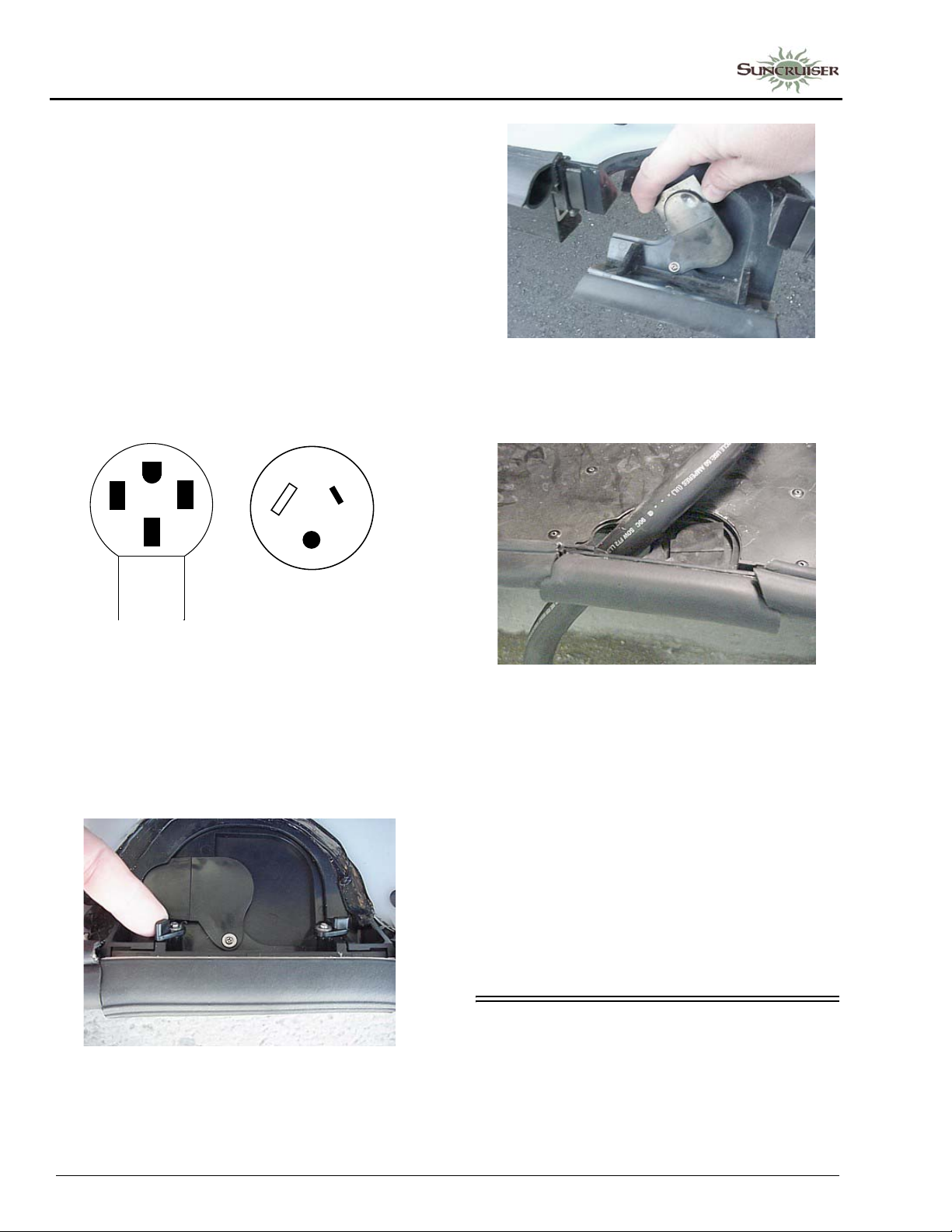
SECTION 6 –
Power Receptacle
30 Amp Receptacle
ELECTRICAL
be used is designed to mate with the prongs of the
power cord plug, the electrical connection can be
expected to carry rated load.
Connecting The Power Cord
To connect to an external source, remove the
cord from the utility compartment and plug it into
a suitable 50-amp power receptacle to provide
external power to the coach and converter/
charger system.
NOTE: Some parks do not have 50-amp service
available, so you will need to connect to
a standard 30-amp service pole using an
adapter.
3. Route the cord through the notch and flip the hatch back up into place and close the compartment door.
50 Amp.
A flip-down hatch lets you route the power
cord out the bottom of the compartment so you
can close the compartment door while the power
cord is connected.
1. Flip the hatch downward.
2. Swivel the cover section aside to reveal cord
notch.
NOTE: Always keep service access passage
closed while utility connection is not in
use.
Park Fuses or Breakers
Most campgrounds are equipped with a fuse
or circuit breaker at the receptacle. This protects
the park’s wiring, as well as the power cord on
your vehicle, from electrical damage. If electrical
power fails, contact the park attendants and have
them check the fuse or breaker for your supply
receptacle.
After disconnecting the power cord, neatly
stow it in the utility compartment.
INVERTER UNIT – 1000W
–If Equipped
The inverter unit is located on the wall of the
utility compartment.
6-2
Page 65
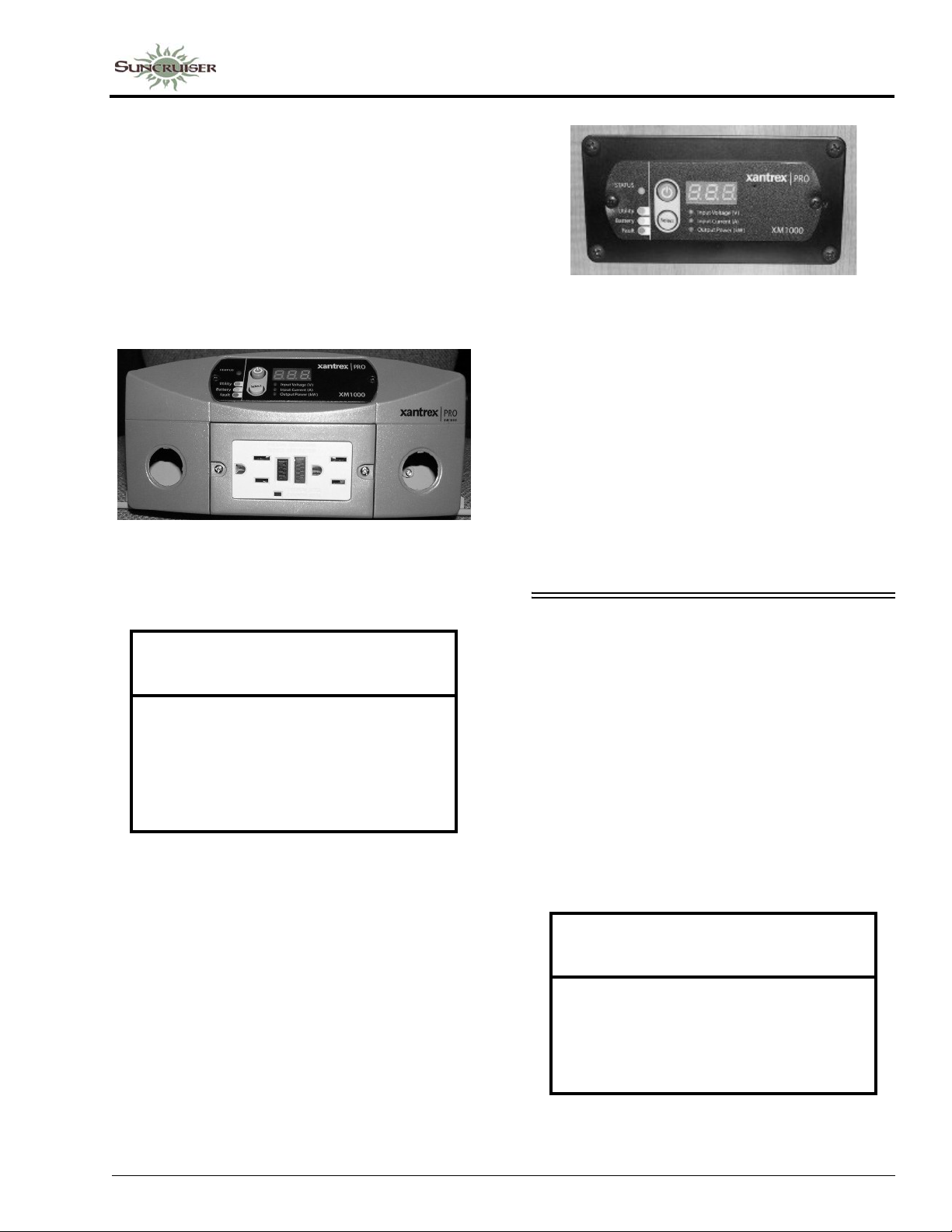
NOTE: The inverter is not intended for steady
use while “dry camping”. Batteries will
deplete quickly with use of the inverter.
The inverter is intended for limited, short
term power usage when not connected to
shoreline or generator power.
The inverter can also be used while
driving the motor home because the
engine alternator will charge the
batteries while driving.
Inverter Charger Unit
(Located inside utility compartment)
-Typical View
SECTION 6 –
ELECTRICAL
Inverter Control Panel
(Located near monitor panel)
-Typical View
When the inverter is not being used, it should
be shut off at the control panel. The inverter
could drain the house batteries if the shoreline is
not connected to external power and the House/
Coach Battery Disconnect switch is on.
Further Information
See the inverter control panel instructions in
your InfoCase for complete instructions and
charging setup directions.
NOTICE
Do not store items too closely around the
inverter unit in the storage compartment.
The inverter generates heat while
operating and needs unrestricted airflow
for proper cooling. Damage to the inverter
can result.
The inverter changes 12-volt DC battery
power into 120-volt AC power for use by 120volt AC equipment inside the coach.
Inverter Control Panel
–If Equipped
The inverter has a wall-mounted monitor/
control panel. It will also display warnings for
overload conditions or other operating failure
conditions.
POWER CENTER
(Converter)
The power converter is generally located
under a cabinet in the galley, living area, or in the
power cord compartment, depending on the
floorplan of your model.
The power converter changes 120-volt AC
current from the auxiliary generator or the
shoreline into 12-volt DC current for use by 12volt equipment in the motor home.
NOTE: The converter will not change 12-volt
DC current to 120-volt AC.
NOTICE
Do not block the converter cover vents in
any way. The converter generates heat
while operating and needs unrestricted
airflow for proper cooling. Damage to the
converter can result.
6-3
Page 66
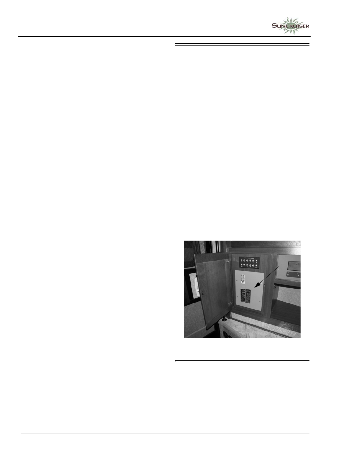
SECTION 6 –
ELECTRICAL
Further Information
See the manufacturer’s operation, care and
maintenance information in your InfoCase.
Charging Section
The converter charges house batteries while
120-volt external power is connected. The
converter will automatically “sense” the
condition of the battery. If it is below “full
charge”, the Charging Section will start charging
the batteries.
If the house batteries have been extremely
discharged, they will accept charge at a relatively
high amperage rate. If they are only slightly
discharged, they will charge at a lower amperage
rate. The rate of charge will decrease as the
batteries reach “full charge”, then will continue
“trickle” charging at a very low amperage rate. If
your battery does not charge as described above,
it is possible the battery is defective.
CIRCUIT BREAKERS – HOUSE 120-VOLT AC
The breaker panel protects all 120-volt
components in the motor home from either an
overload on the circuit or a short in the wiring or
component itself. When an overload or short
develops, the breaker will open preventing
damage to the system.
Shut off the equipment (example: roof air
conditioner) and allow a brief cooling period.
Then reset the breaker by moving the switch to
“Off” and back to “On”. If the breaker is
continually tripped and no overload is evident,
have the system checked for a short in the wiring
or the appliances.
The breaker panels are located behind a door
or pull-off panel on a lower cabinet face in either
the galley or lounge area or beneath the rear bed,
depending on model.
Thermal Overload
A thermal overload device inside the
converter will shut down the converter if it
becomes overheated. This can result from
operating above its maximum limit for an
extended period of time or by obstruction of
ventilation to unit.
NOTE: The 12-volt loads will automatically be
powered by the house battery power in
this event.
The thermal overload will reset itself after a
period of time, and the lights and motors will
again resume operation from the power converter
section. If the breaker trips again shortly after
reset, take immediate steps to correct the cause of
overheating. A portion of the house 12-volt load
(lights or motors or both) should be turned off to
reduce total load. Also, inspect the power
converter to make sure ventilation is not
obstructed.
NOTE: Breakers are labeled on panel.
Arrangement may vary according to
appliance and equipment options.
-Typical View
ELECTRICAL OUTLETS – HOUSE 120-VOLT AC
A number of standard household electrical
outlets are provided throughout the coach for
connecting small appliances such as televisions,
radios, toasters, etc.
6-4
Page 67
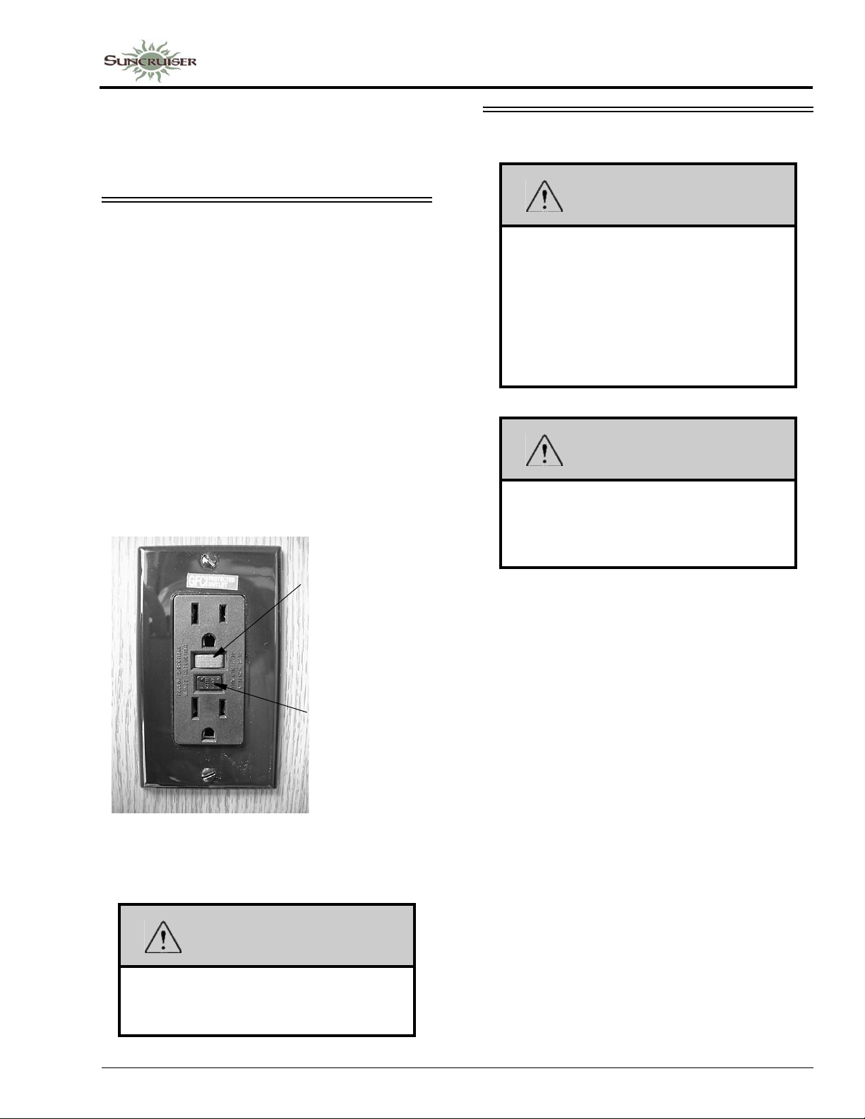
An exterior outlet is also located on the
outside of the coach near the entrance door or in
a storage compartment on the passenger side of
the coach.
SECTION 6 –
ELECTRICAL
ELECTRICAL GENERATOR
GROUND FAULT CIRCUIT INTERRUPTER
Bath, galley, and exterior outlets are
connected to a GFCI (Ground Fault Circuit
Interrupter), which is an extremely sensitive
circuit breaker that will help to protect against
severe electrical shock if a ground fault develops.
If such a condition occurs, the GFCI will break
the circuit by turning off the power to the
protected outlets. Should this occur, unplug all
the appliances on that circuit and press the reset
button on the GFCI equipped outlet.
If the GFCI keeps tripping, have the electrical
system checked and repaired, if necessary, before
using again.
• Push to Reset
circuit after
monthly testing
or ground fault
tripping.
• Push to Test at
least monthly.
Should break
circuit. Press
Reset button to
reconnect.
WARNING
Careless handling of the generator and
electrical components can be fatal.
Never touch electrical leads or appliances
when your hands are wet, or when
standing in water or on wet ground.
Do not attempt to repair the generator
yourself. Service should be performed by
a qualified service center.
WARNING
Do not plug the power cord into the
generator receptacle while the generator
is running. Electrical shock can cause
personal injury.
Automatic Power Transfer Switch
–If Equipped
Whenever the Generator is started, an
automatic power transfer system automatically
switches the household electrical system to the
Generator approximately 10 seconds after the
Generator is started. The 10 second delay allows
the Generator to start easily without the burden of
electrical loads.
GFCI Outlet
(Ground Fault Protector)
WARNING
The GFCI will not completely eliminate
the risk of electrical shock. Infants and
small children may still be affected.
6-5
Page 68
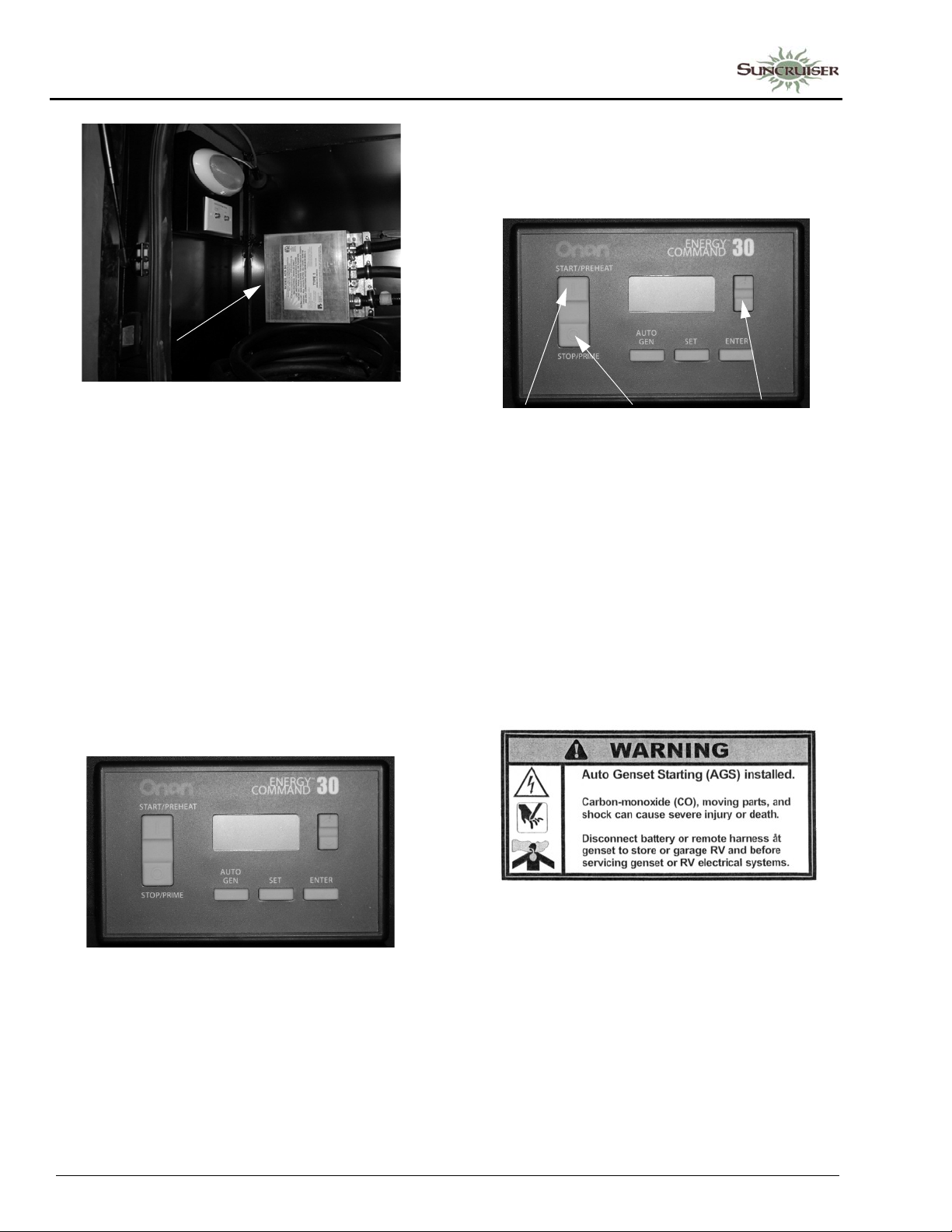
SECTION 6 –
ELECTRICAL
Automatic Power Transfer Box
(Located inside or behind
utility compartment)
-Typical Installation
Automatic Generator Start (AGS)
-If Equipped
The Automatic Generator Start feature
monitors house battery voltage and coach interior
temperature, and has the ability to automatically
start the Generator to help maintain full air
conditioning function and house battery charge.
The AGS control pad is also equipped with an
hourmeter feature, which registers the total
number of hours that the generator has been
operated.
To Stop the Generator
Press and Hold the “Stop/Prime” button on the
AGS Control Pad until you hear the Generator
come to a full stop, then release.
• Press and
Hold to start
Generator
• Press and
Hold to stop
Generator
• Press Up/Down to
scroll to desired
screen for Generator
Hourmeter reading
NOTE: Your coach may be equipped with two
additional Generator power switches
(located on the dash and on the
generator itself), depending on model.
The following label is located near the 120volt house circuit breaker panel and at the
Generator to warn you to disconnect specific
electrical connections before servicing the
Generator and storing the coach.
AGS Control Pad
(Located near monitor panel)
Generator Operation
(if equipped with AGS)
To Start the Generator
Press and Hold the “Start/Preheat” button on
the AGS Control Pad until you hear the
Generator running smoothly, then release.
6-6
See the AGS user guide for more information
to help understand the AGS feature and its
operation with your Generator.
Generator Operation
(Not available on coaches equipped with AGS)
NOTE: If the GenSet Start or Stop switch is
momentarily pressed, the monitor panel
will automatically try to start or stop the
Generator. It will try 4 times (10 second
crank, 10 second rest).
Page 69
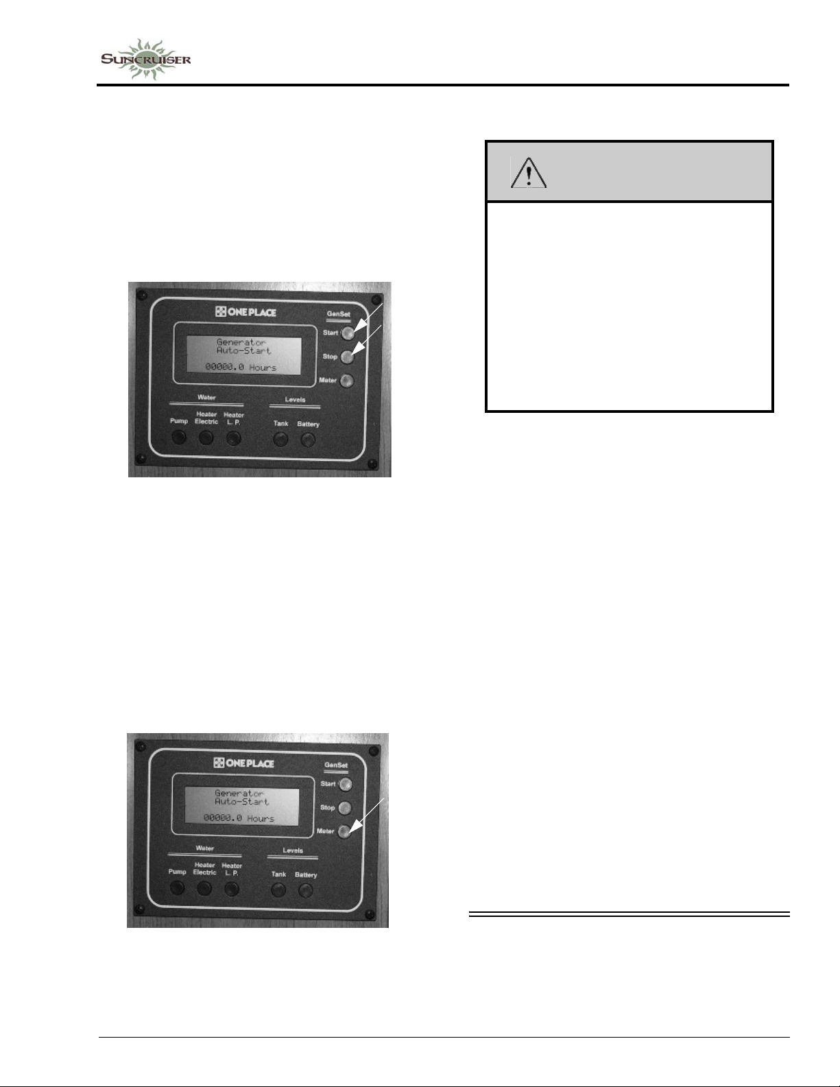
SECTION 6 –
ELECTRICAL
To Start the Generator
Press and Hold the GenSet Start button until
you hear the Generator running smoothly, then
release.
To Stop the Generator
Press and Hold the GenSet Stop button until
you hear the Generator come to a full stop, then
release.
Generator Start/Stop Buttons
(Located on monitor panel)
-Typical View
Operation Warnings and Cautions
WARNING
The exhaust of all internal combustion
engines contains carbon monoxide (CO).
This poisonous gas is colorless, odorless,
tasteless, and lighter than air. The
exhaust systems of both your motor home
engine and your generator engine have
been installed with your safety in mind.
However, certain precautions must be
taken when using them to protect yourself
from conditions beyond the control of the
manufacturer.
• Do not simultaneously operate the Generator
and a power vent, which could draw exhaust
gases into the vehicle.
• Do not open windows or vents on the end or
side of the vehicle where exhaust pipe of the
Generator is located.
Generator Hourmeter
The Generator hourmeter registers the total
number of hours that the Generator has been
operated. Press the GenSet Meter button once to
get reading.
Refer to the hourmeter to determine when
periodic maintenance is due and to record
services which have been performed.
Generator Hourmeter Button
-Typical View
• Park the vehicle so that the wind will carry the
exhaust away from the vehicle. Also, note the
position of other vehicles to be sure their
exhaust will not enter your vehicle.
• Do not operate the Generator engine while
parked if vegetation, snow, buildings,
vehicles, or any other object can deflect the
exhaust under or into the vehicle.
Check Generator oil level frequently during
periods of use. Refer to the Generator
manufacturer’s user guide provided in your
InfoCase for specific recommendations.
Further Information
Refer to the Generator manufacturer’s user
guide provided in your InfoCase for specific
recommendations, operating instructions and
cautions, troubleshooting, and maintenance.
ELECTRICAL SYSTEM – HOUSE 12-V OLT DC
The DC voltage system consists of the chassis
battery, the 12-volt house batteries, and the 12volt power converter.
6-7
Page 70
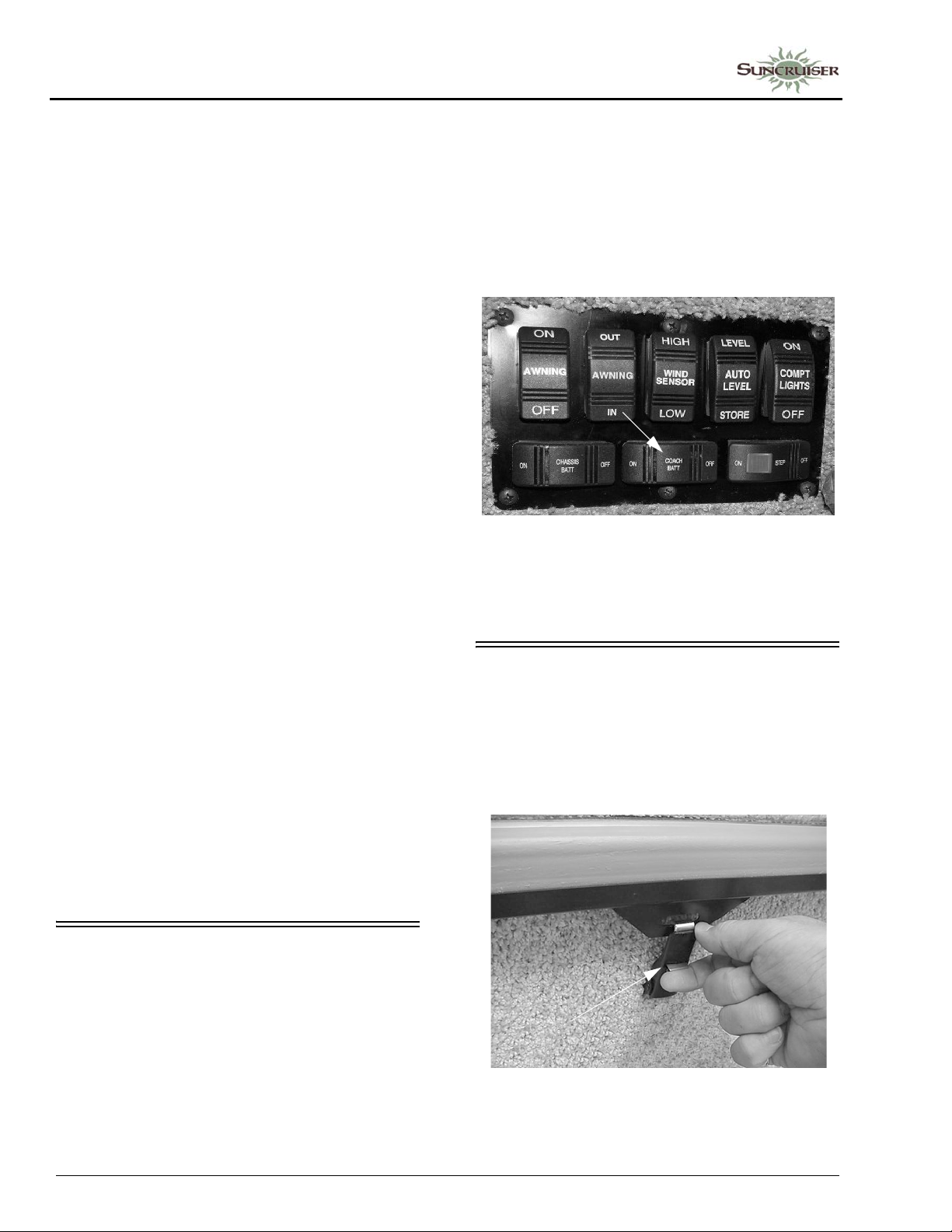
SECTION 6 –
ELECTRICAL
Converter
See “Power Center.”
Chassis Battery
The chassis battery is used to operate the
engine starter and automotive accessories and
controls found on the instrument panel. The
slideout room systems and the electric step are
also connected to the chassis battery.
See your chassis manual for further
information on chassis batteries and chassis
electrical system.
House Batteries
House batteries are “deep-cycle” type
batteries specially designed for recreational
vehicle use. They will provide longer lasting
power than standard automotive starting batteries
and will withstand the frequent drain-andrecharge cycles that occur under the demanding
conditions of a camping outing.
The house batteries supply power to 12-volt
equipment located in the living area of the motor
home. This includes the following 12-volt
powered components (if equipped): interior 12volt lighting, range exhaust fan, propane furnace
fan, fresh water pump, systems monitor panel
with water level and holding tank gauges,
refrigerator, roof vent fans, and 120-volt
electrical generator starter.
The house batteries can also provide
emergency power to start the engine if the chassis
battery is discharged. (See “Battery Boost
Switch” or “Aux Start Switch”).
House batteries are automatically charged by
the chassis alternator while the engine is running.
Always leave this switch ON while using the
coach.
NOTE: Some electronic displays and memory
functions may need to be reset after
power has been reconnected.
See also “Battery Care” elsewhere in this
section.
House/Coach Battery Disconnect Switch
(Located near entrance door)
-Typical View
BATTERY ACCESS
The house/coach batteries (and chassis
batteries in certain models) are located in a
compartment beneath the interior entrance steps.
• Unfasten the step retainer, then lift the step
upward and remove to service batteries.
HOUSE/COACH BATTERY DISCONNECT SWITCH
(COACH BATT)
The House/Coach Battery Disconnect switch
lets you disconnect the house batteries from the
12-volt system of your coach during storage
periods to avoid battery drain by electrical items
that are hooked directly to the house batteries,
such as clock displays and radio memories, etc.
6-8
• Squeeze tab upward
to release latch
-Typical View
Page 71
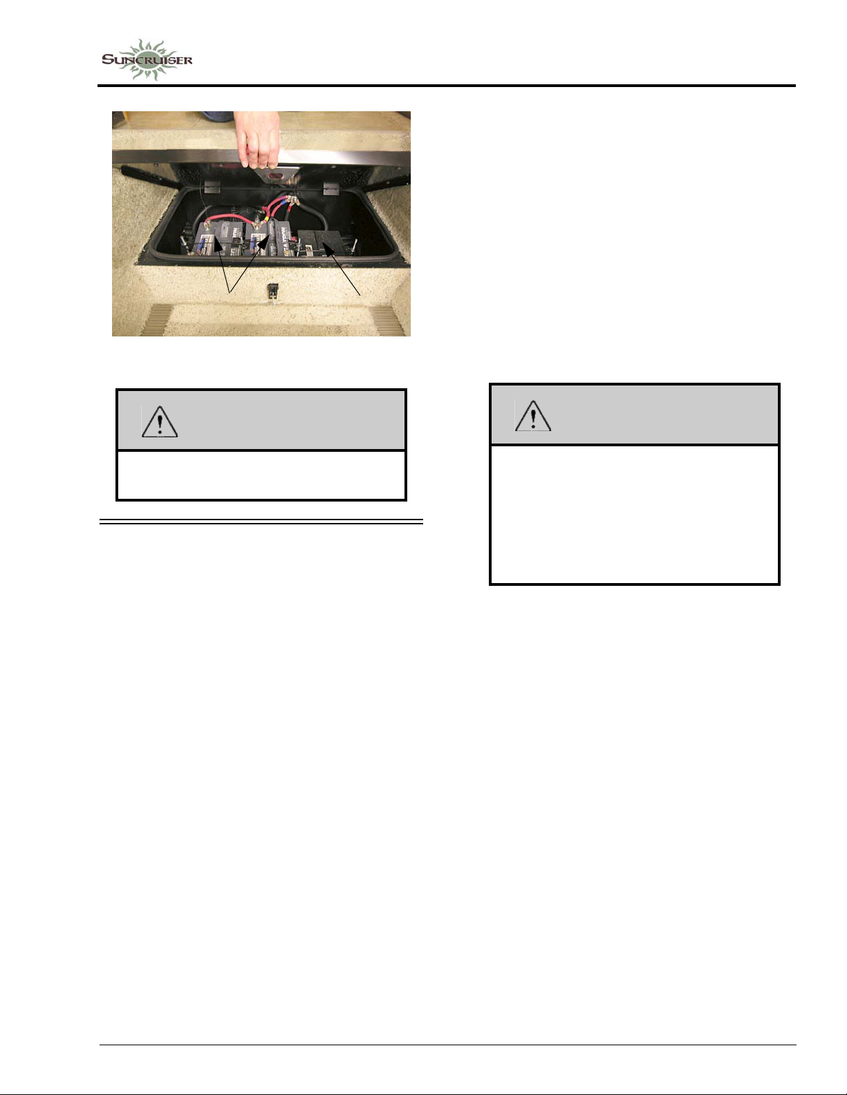
House
Batteries
-Typical View
Chassis
Battery
SECTION 6 –
ELECTRICAL
The two best defenses against sulfating and insufficient charge are to:
1. Turn of f the House/Coach Battery Disconnect switch to avoid parasitic discharge (the trickle discharge caused by directly connected components like propane gas detectors or digital clock displays, etc.)
2. Check the battery and recharge as necessary at least once a month during long storage periods. Turn the House/Coach Battery Disconnect switch off to avoid electrical arcing when attaching or detaching charger clamps.
WARNING
Always refasten the battery retainer when
returning a battery to the compartment.
BATTERY CARE
Lead-acid type batteries are electro-chemical
devices for storing and releasing electrical
charge. As such, they are simply an electrical
reservoir, not an electrical source. As soon as
energy is removed from the battery, it should be
replaced by the engine alternator or the coach
converter system.
If a battery sits unused for 30 days or more,
especially during warm weather, it can develop a
deposit of sulfate crystals on the metal plates
inside the battery. This condition is called
“sulfating” and prevents the battery from either
releasing or accepting a charge. If this condition
occurs, the battery must be replaced.
If a battery does not contain at least 80%
charge during freezing temperatures, the
electrolyte can freeze and crack the battery case.
WARNING
California Proposition 65 Warning:
Battery posts, terminals, and related
accessories contain lead and lead
compounds, chemicals known to the
state of California to cause cancer and
reproductive harm. Wash hands after
handling.
NOTE: We do not recommend leaving the
shoreline plugged in continuously during
storage periods because the batteries
can lose electrolytic fluids and become
damaged from continuous charging
without periodic use or maintenance.
We recommend following regular battery
inspection and maintenance, especially
in cold weather.
Further precautions are:
• Remove the battery from the coach.
• Store it in a cool place.
• Check the state of charge periodically to avoid
discharge or sulfating.
To ensure that the battery will always accept
and hold a charge, follow these simple
maintenance practices:
• Make sure the batteries always remain
securely clamped in the battery tray.
6-9
Page 72
SECTION 6 –
ELECTRICAL
• Make sure battery cable clamps are tight on
the terminal posts and are free of corrosion.
• Neutralize corrosion buildup or acid film on
top of battery by washing with a baking soda/
water solution. Rinse with clear water.
NOTE: Make sure vent caps are on securely to
prevent baking soda solution from
entering the battery and contaminating
the electrolyte fluid.
WARNING
Before removing any battery cables or
battery, make sure all 12-volt equipment
in the motor home is off and the power
cord has been disconnected. Be sure to
replace the battery terminal boot, if
supplied, back onto the positive terminal
after servicing. Care must be taken to
avoid pinching the cable between any
metal parts. Should the cable be
damaged, a short circuit could result in
personal injury or damage to equipment.
Replace any damaged cables at once.
Always remove jewelry and wear
protective clothing and eye covering
when checking or handling batteries.
WARNING
To prevent wiring damage, it is essential
when replacing the cables on the battery ,
or when using a “booster” battery , that the
positive post and the positive cable be
attached and the negative post and
negative cable be attached. The posts are
marked (+) plus and (-) minus.
If a “boost charger” is used while battery
is in the motor home, disconnect both
battery cables before connecting the
charger to avoid damage to engine
electronic components.
Never attempt to charge or boost a frozen
battery . An explosion can occur resulting
in personal injury.
Chassis Batteries
If your coach is going to be unoccupied for
two weeks or more, Winnebago Industries®
recommends disconnecting the chassis batteries
in your coach to avoid battery discharge.
Turn the Chassis Battery Disconnect switch
(located near the entrance door) to the OFF
position to disconnect batteries.
• Clean and tighten battery terminals and have
the specific gravity checked at least once a
year.
• Check the battery fluid level every month, or
more often in hot weather. Fill to
approximately 3/8 inch above the plates. DO
NOT OVERFILL. If fluid is added during
freezing weather, the motor home should be
driven several miles to mix water and
electrolyte to prevent freezing.
• Fluid level check may be omitted if equipped
with maintenance-free batteries.
6-10
CIRCUIT BREAKERS – HOUSE 12-VOLT
All 12-volt circuits and equipment in the
coach area of the motor home are protected by
the breaker panel. When a circuit is overloaded or
a short develops in any part of the system, a fuse
or breaker will shut down that circuit. If this
happens, turn off all affected lights or appliances
and reset the breaker or replace the fuse with a
new one of equal amperage rating.
House Breaker Panel
The House 12-Volt Breaker Panel is located
behind a cabinet door near the galley, below the
refrigerator, or under the bed, depending on
model.
Page 73
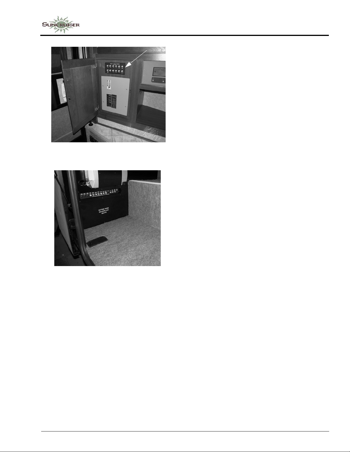
House 12V Circuit Breaker Panel
-Typical View
SECTION 6 –
ELECTRICAL
Auto Chassis 12V Circuit
Breaker Panel
(Located inside passenger
side compartment)
-Typical View
A label on the panel states the amperage rating
and circuit protected for each fuse or breaker.
NOTE: Breakers are labeled on panel.
Arrangement may vary according to
appliance and equipment options.
Battery Charge Meter
See related item under “Systems Monitor
Panel” in Section 4 - Appliances and Systems.
Battery Boost Switch
See Section 3 - Driving Your Motor Home for
information on the Battery Boost switch.
6-11
Page 74

Page 75
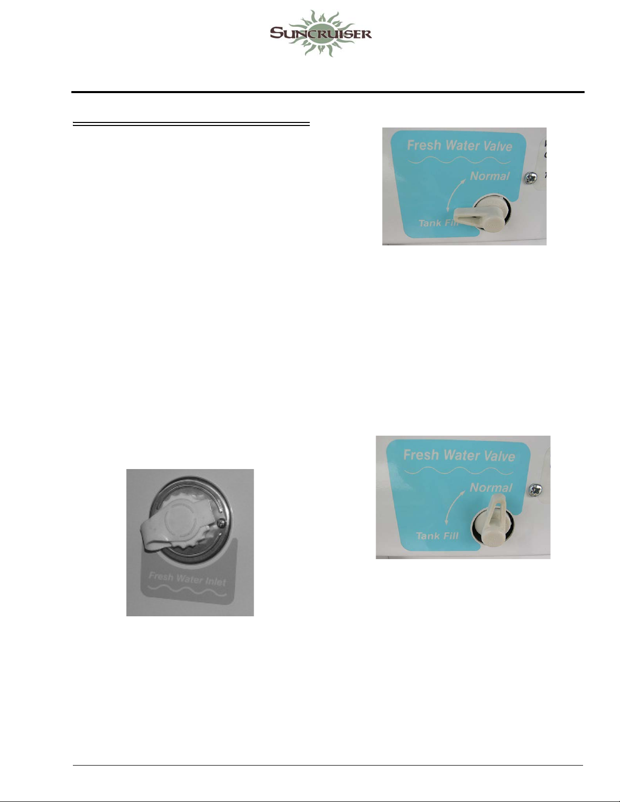
SECTION 7 – PLUMBING
FRESH WATER SYSTEM
The fresh water system provides water to the
galley sink, shower, bathroom lavatory, toilet,
and water heater. Water may be supplied by
either of two sources:
• a fresh water tank and water pump located
within the motor home; or
• any external fresh water source to which the
motor home may be connected, known as
“city water.”
Fresh Water Valve in Tank Fill position
(Located in water service center)
Filling the Fresh Water Tank
Always fill the fresh water tank at an approved
potable water filling facility or a known purified
drinking water source.
The tank is filled through the city water
connection (Fresh Water Inlet) inside the water
service center.
The Fresh Water Valve routes the water from
the city water hose to the fresh water tank for
filling.
1. Attach hose to the Fresh Water inlet.
3. Turn city water supply on.
4. T ank is full when water flows from tank vent tube beneath coach.
5. Turn off city water supply and disconnect from city water connector.
6. Turn Fresh W ater Valve to Normal position to
use the water pump. The Tank Fill position is
only for pressure filling the water tank from
the city water hose connection.
5 - DASH / AUTO
Fresh Water Valve in Normal use position
(Located in water service center)
Fresh (City) Water Connection
2. Turn the Fresh Water Valve to Tank Fill position.
Using City Water
When connected to an outside source of water,
the water bypasses the demand pump and storage
tank and supplies pressure directly to individual
faucets and toilet. A check valve built into the
pump prevents water from entering the pump and
filling the storage tank.
1. Connect hose to city water connection as
described in previous steps.
7-1
Page 76
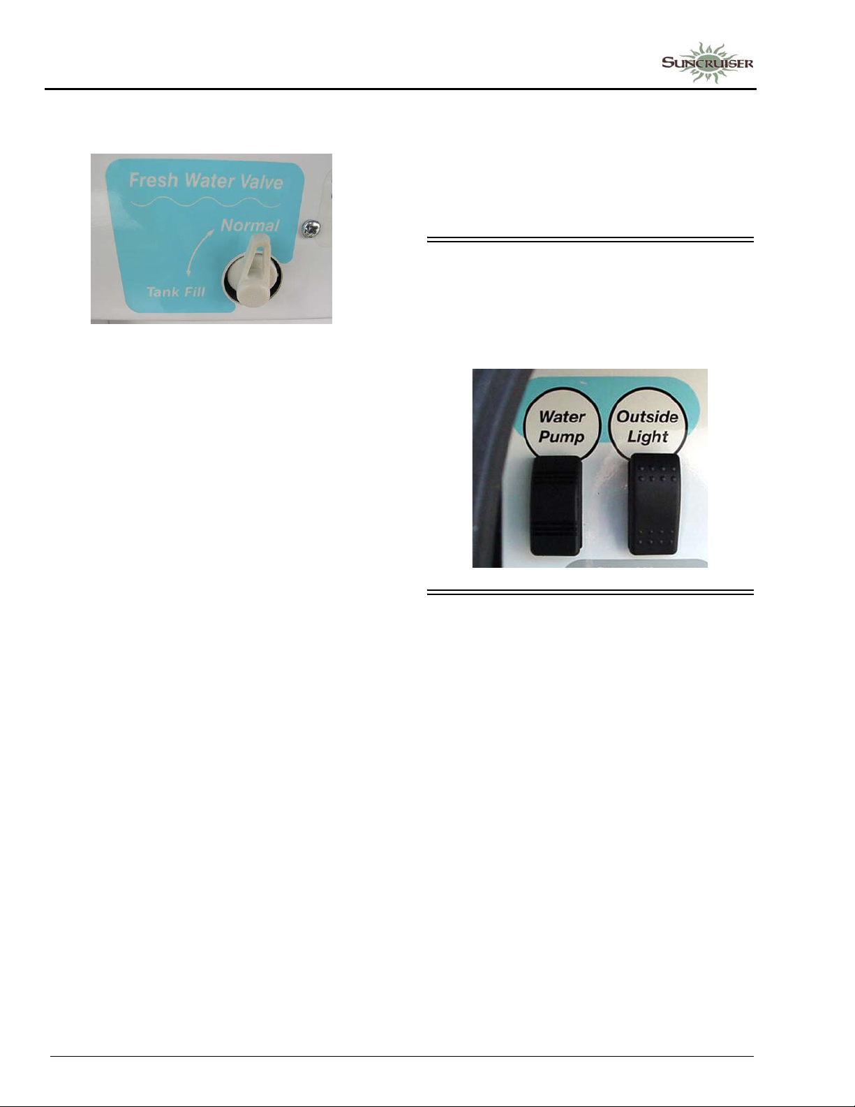
SECTION 7 –
PLUMBING
2. Turn Fresh Water Valve to Normal position and turn the water pump switches OFF.
Fresh Water Valve in Normal use position
(Located in water service center)
NOTE: Always keep the tank fill valve in Normal
position unless you are filling the tank. If
this valve is left in the Tank Fill position
while using the city water, water will
keep flowing into the tank and out the
tank vent tube onto the ground and the
water pump will run without delivering
water to faucets.
These devices simply connect in-line between
the supply hose and the city water input on the
coach.
Water pressure regulators are commonly
available at most RV dealerships and many large
retail discount or home supply centers.
UTILITY LIGHT
A light is located up on the left sidewall to
illuminate the utility hook-up area when needed.
The switch is located in the water service
center compartment.
Disconnecting from City Water
1. Turn the city water source off.
2. Open a faucet on the coach (such as the exterior wash station, if equipped) to relieve line pressure.
3. Disconnect the city water hose from the coach and replace the cap on the fresh water inlet.
NOTE: Be sure the Fresh Water Valve is in
Normal position to use the water pump.
If the valve is in Tank Fill position, the
pump will run continuously without
delivering water.
Pressure Regulators
Because city water pressure varies from
location to location, we recommend obtaining an
in-line water pressure regulator to prevent
damage to any components, connections, and
seals in your fresh water system.
We recommend a regulator that controls water
pressure to 50 psi. max.
WATER PUMP
When your coach is not connected to a city
water supply, water is supplied from the fresh
water tank by a water system demand pump. A
demand pump is designed to run only when you
are using water. When you open a faucet, the
waterline pressure drops and the pump begins to
run, and it will continue to run as long as the
faucet is open. When you close the faucet, the
line pressure backs up to the pump, and it shuts
itself off.
The pump is self-priming and will run briefly
to build up line pressure when the Water Pump
switch is first turned on. See “Initial Waterline
Priming” for instructions on using the water
system for the first time.
Further Information
See the water pump manufacturer’s operation,
care, and maintenance information in your
InfoCase.
7-2
Page 77
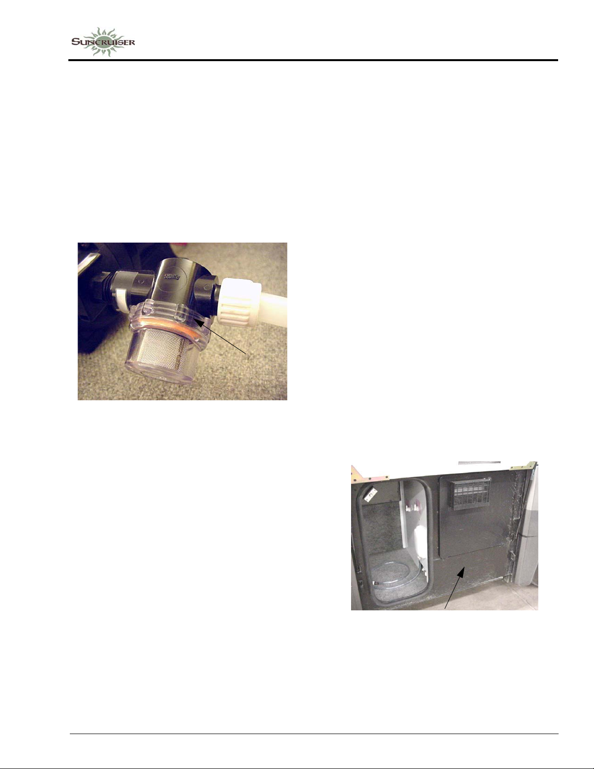
SECTION 7 –
PLUMBING
Pump Strainer
The pump is equipped with a cleanable
strainer to capture any possible tank-borne
particles that could damage pump components.
NOTE: We recommend that you check and clean
the strainer after each tankful of water
during the first few uses of the water
pump system. Thereafter, remember to
check it at least yearly, and be sure to
empty water from it during winterization
procedures.
Unscrew bowl
and remove to
clean strainer
Water Pump Strainer
-Typical View
To Clean Pump Strainer
• Be sure all water pump switches are OFF.
While the switch is “ON”, the pump will
automatically supply water as it is needed.
We recommend that you turn the water pump
switch off whenever you will be away from the
vehicle or not using the water system. In time, a
slow leak in a faucet could drain the water tank,
fill the holding tank, and discharge the house
batteries.
Initial Waterline Priming
1. Make sure that all water drain valves are
closed, including water heater valve.
2. Turn water pump switch to “OFF” position.
3. Fill water tank.
4. Open all faucets, hot and cold.
5. Turn on water pump switch.
6. Close each faucet as it begins to deliver a
steady stream of water (close cold water first).
Leave hot water faucets on until they also
deliver a steady stream of water. This will
ensure that the water heater is filled with
water.
7. Check to be sure pump stops soon after all
faucets have been closed.
8. Pump is now ready for automatic operation.
Pump will start when a faucet is opened and
stop when the faucet is closed.
• Twist the inlet cap (bowl) counter-clockwise
to unscrew from the strainer assembly.
• Remove the bowl and pull the strainer screen
out of the bowl to tap out any particles and
rinse clean.
• Insert the strainer screen back into the bowl,
then screw the bowl back onto the strainer
assembly.
NOTE: You must also empty the strainer when
winterizing your coach to avoid water
freezing and cracking the filter bowl.
Water Pump Switch
The water pump switch is located near the
monitor panel (some models may have an
additional switch in the water service center or
within the bathroom area for your convenience).
Water Pump Access Panel
(Your model may or may not be
equipped with an access panel)
-Typical View
7-3
Page 78
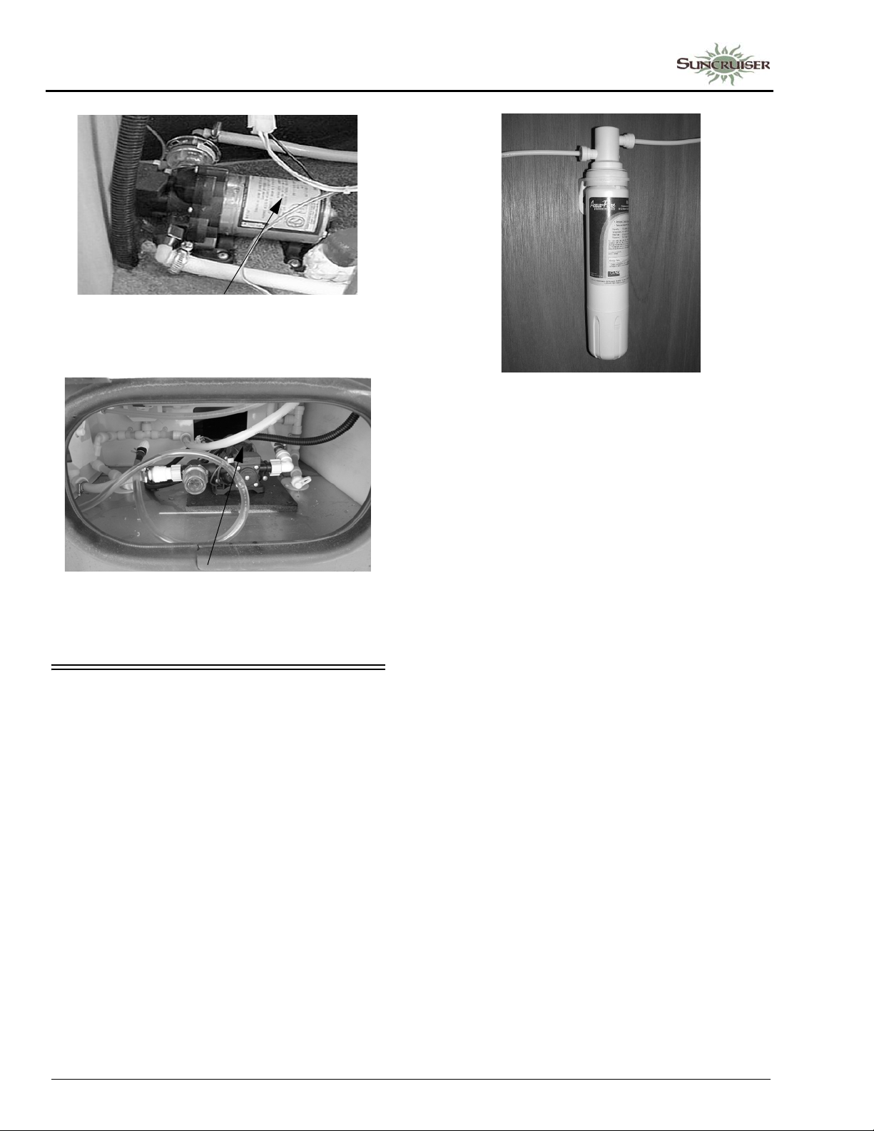
SECTION 7 –
PLUMBING
-Typical Installation
Water Pump
Ice Maker Filter Assembly
(Located below galley sink)
-Typic al Installation
Water Pump
(Located in passenger compartment)
-Typical Installation
ICE MAKER WATER FILTER
–If Equipped
If the refrigerator in your coach is equipped
with an ice maker, an ice maker filter is provided,
which removes chlorine and odors for clean,
taste-free ice cubes.
Replacing the Ice Maker Filter Cartridge
The filter cartridge must be replaced at least
every 12 months, or when water flow from the
filtered water faucet is too slow for convenience.
• Place a container beneath the filter to catch
any water remaining in the waterlines during
filter removal.
• Twist the filter cartridge counter-clockwise
(to the left) about one-quarter turn, then pull it
down and out of the filter socket. (A springloaded valve inside the filter socket will block
water from flowing out of the socket when the
filter cartridge is removed).
• Insert a new filter cartridge up into the filter
socket as far as possible and twist it clockwise
(to the right) one-quarter turn until it stops.
• Discard the first two batches of ice cubes to
avoid consuming carbon dust or particles that
may have been present in the new filter
cartridge.
• See “Winterization Procedure” at the end of
this section for further information.
7-4
NOTE: When removing the coach from storage,
always disinfect and flush the water
system thoroughly before installing a
new filter.
Page 79
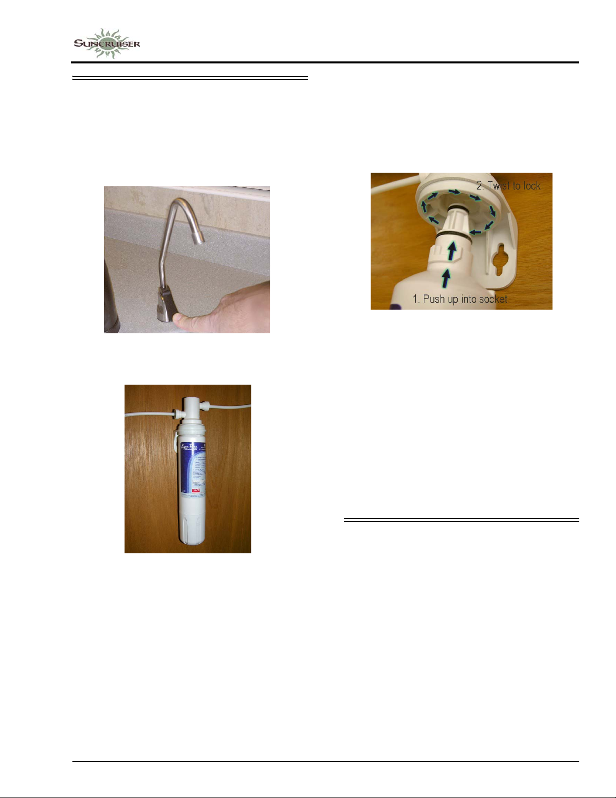
FILTERED WATER FAUCET
–If Equipped
The filtered water faucet is connected to a
flow-through, activated carbon filter cartridge
that removes chlorine and odors for taste-free
drinking water.
Filtered Water Faucet
-Typical View
SECTION 7 –
PLUMBING
loaded valve inside the filter socket will block
water from flowing out of the socket when the
filter cartridge is removed.)
• Insert a new filter cartridge up into the filter
socket as far as possible and twist it clockwise
(to the right) one-quarter turn until it stops.
• Purge a new filter cartridge before using for
drinking. Run a few gallons of water through
the filter and discard the water (or use for
watering plants) to avoid ingesting carbon
dust or particles that may have been present in
the new filter cartridge.
Water Filter Assembly
(Located below galley sink)
-Typical View
Replacing the Water Filter Cartridge
Replace the filter cartridge when water flow
from the faucet is too slow for convenience.
• T wist the filter cartridge counterclockwise (to
the left) about one-quarter turn, then pull it
down and out of the filter socket. (A spring-
• See Winterization Procedure at the end of this
section. Also see filter manufacturer’s
information in your InfoCase for further
instructions or precautions.
• When removing the coach from storage,
always disinfect and flush the water system
thoroughly before installing a new filter.
DISINFECTING YOUR FRESH WATER SYSTEM
To ensure complete disinfection of the potable
water system, it is recommended that the
following procedure be followed on a new
system, one that has not been used for a period of
time, or one that could have become
contaminated.
This procedure is also recommended before
long periods of storage such as over winter.
7-5
Page 80
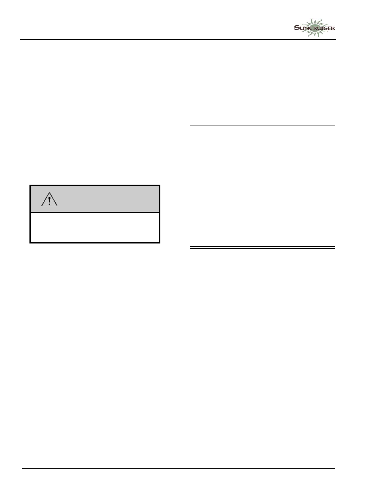
SECTION 7 –
PLUMBING
City Water Hose Disinfection
NOTE: This procedure can be used periodically
to sanitize the city water hose, and can
be used as an alternate method of adding
bleach solution to the fresh water tank if
desired.
1. Connect your city water hose to the fresh water inlet of your coach.
2. Hold the “city end” of the water hose upright and use a funnel to pour 1 1/2 cups of household chlorine bleach (sodium hypochlorite solution) into the hose. Keep the end of the hose held upright to avoid draining the bleach solution.
WARNING
Chlorine is poisonous. Do not misuse.
Recap bottle and clean all utensils after
use.
will result in a 6.7 ppm level of chlorine,
which should kill harmful bacteria and slimeforming organisms.
• Chlorine will be removed from drinking water
by the full-coach filter and cold water filter at
the galley.
• Superchlorination does not affect city water
usage, only the fresh water tank.
SHOWER HOSE VACUUM BREAKER
After using the shower, you may notice water
dripping from the shower faucet assembly. The
dripping results when vacuum in the shower hose
(after closing the shower faucet) slowly releases
and allows water remaining in the hose to drain
down. This is a normal function of the shower
valve assembly and is not a leak or defect.
If items are placed into the shower tub before
shower valve vacuum release is complete, they
may become wet.
3. Connect the hose to a city water hydrant and turn on slowly , allowing the water to force the bleach through the hose, then continue filling the tank with water. (This will disinfect the city water hose at the same time).
4. Let the system stand at least 4 hours when
disinfecting with 50 ppm residual chlorine.
If a shorter time period is desired, then a 100
ppm chlorine concentration (double the
amount of bleach) should be allowed to stand
in the system for at least 1 hour.
5. Drain the chlorinated water from the fresh water tank and refill with clean water.
Continuous Tank Disinfection (Superchlorination)
Some RVers like to ensure continuous
sanitation of their fresh water tank by
“superchlorination”– maintaining an effective
low level of chlorine in the tank at all times.
• Add 1 teaspoon of chlorine bleach (sodium
hypochlorite) to your tank for each 10 gallons
of tank capacity. When you fill the tank, this
EXTERIOR SHOWER/WASH STATION
–If Equipped
The exterior wash station feature allows you
to do things such as rinse off sand or salt after a
swim, rinse off muddy boots, or bathe your pet
outside the coach. Some models may have a
water pump switch located near the shower
faucet for convenience.
7-6
Page 81
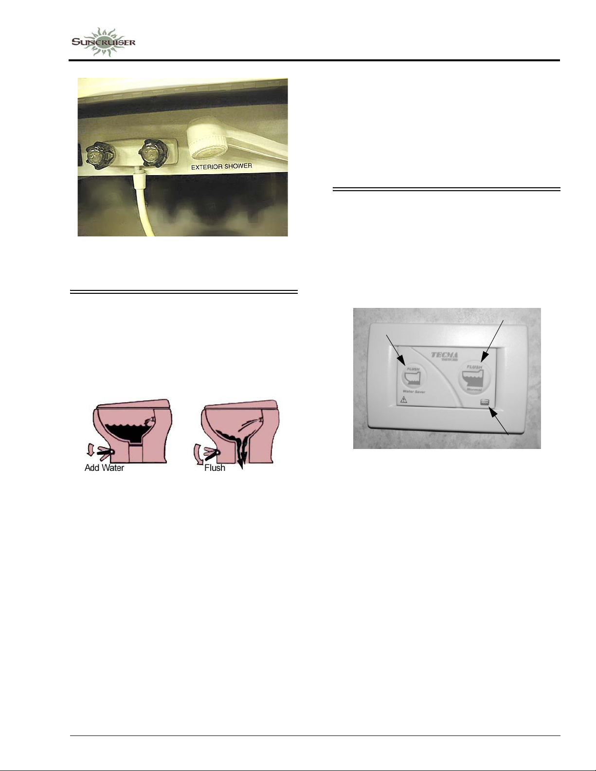
SECTION 7 –
PLUMBING
Exterior Shower/Wash Station
-Typical View
TOILET
The toilet in your motor home is very similar
to the household type, except that it is designed to
use only a small amount of water per flush. It
uses a high velocity jet of water, producing a
swirl effect, to efficiently cleanse the bowl.
See winterizing instructions at the end of this
section to prepare the toilet for storage in freezing
conditions.
Further Information
See the toilet manufacturer’s operation
information in your InfoCase for complete
operating, care, and maintenance information.
TOILET - ELECTRIC FLUSH
-If Equipped
Your coach may be equipped with an electric
macerating toilet, which provides powerful, yet
whisper quiet operation. It is equipped with a
wall-mounted push button control and operates
on minimal water consumption.
Water
Saver Flush
Normal Flush
Important “Don’ts”
• Don't use facial tissue or regular toilet tissue in
the RV toilet. These will not disintegrate
sufficiently and will often cling to the sides of
the holding tank. Toilet tissue made
specifically for use in RV toilets and holding
tanks is available at most RV supply centers.
• Don’t dispose of sanitary napkins or other
non-dissolving items in the toilet.
• Don’t put automotive antifreeze or caustic
chemicals, such as laundry bleach or heavy
detergents into the toilet or holding tank.
These products may damage plastic or rubber
parts in the system.
LED Symbol
Wall Switch/Controller
(Located on wall near toilet)
Water Saver Flush Button
• Press and release to flush liquids and small amounts
of toilet paper.
Normal Flush Button
• Press and release to flush solids and toilet paper.
NOTE: Press both Water Saver Flush and
Normal Flush buttons simultaneously
and release to empty bowl and leave it
dry for travel. Press either button once to
return to normal use.
LED Symbol
• Symbol not lighted - T oilet is OFF, in sleep mode, or
not receiving power.
• Symbol lighted GREEN - Toilet is ON and the holding
tank is between empty and half full.
• Symbol lighted YELLOW - Toilet is ON and the
holding tank is at least half full.
7-7
Page 82

SECTION 7 –
PLUMBING
• Symbol lighted RED - Toilet system is ON and the
holding tank is full.
Important “Don’ts”
• Don't use facial tissue or regular toilet tissue in
the RV toilet. These will not disintegrate
sufficiently and will often cling to the sides of
the holding tank. Toilet tissue made
specifically for use in R V toilets and holding
tanks is available at most RV supply centers.
• Don’t dispose of sanitary napkins or other
non-dissolving items in the toilet.
• Don’t put automotive antifreeze or caustic
chemicals, such as laundry bleach or heavy
detergents into the toilet or holding tank.
These products may damage plastic or rubber
parts in the system.
See winterizing instructions at the end of this
section to prepare the toilet for storage in freezing
conditions.
Further Information
See the toilet manufacturer’s operation
information provided in your InfoCase for
complete operating, care, and maintenance
information.
DRAINAGE SYSTEM (P-TRAPS)
Ensure there is an adequate amount of water in
the drainage system p-traps to avoid sewer odor
from entering your coach.
If you should experience a sewer odor, pour
approximately 1 cup of water down each sink and
shower drain in the coach.
WASTE WATER SYSTEM
(Holding Tanks)
The drainage system is self-contained and
uses two separate holding tanks to contain the
waste water until it can be dumped at an
appropriate waste water disposal site. This means
you can use the toilet, sinks and shower even in
areas where utility hookups are not available.
The black water holding tank contains the
sewage from the toilet and may include bathroom
lavatory on some models. The gray water holding
tank contains the waste water from the galley
sink and shower, and may include bathroom
lavatory.
See “Specifications” in Section 1 -
Introduction for tank capacities for your model.
Dumping Holding Tanks
1. Remove sewer hose from water service
center.
2. Remove dust cap from drain outlet and
connect sewer hose. Be sure it is firmly
attached.
NOTE:The drain outlet swivels downward when
necessary to avoid bends in the drain
hose which could trap solids while
dumping or to provide more direct
drainage while using on-site sewer hookups.
3. Place the outlet end of sewer hose into
disposal opening.
Washer/Dryer
-If Equipped
In addition to pouring water down sink and
shower drains, also run a wash cycle to ensure
there is an adequate amount of water in the
washer p-trap.
7-8
Page 83
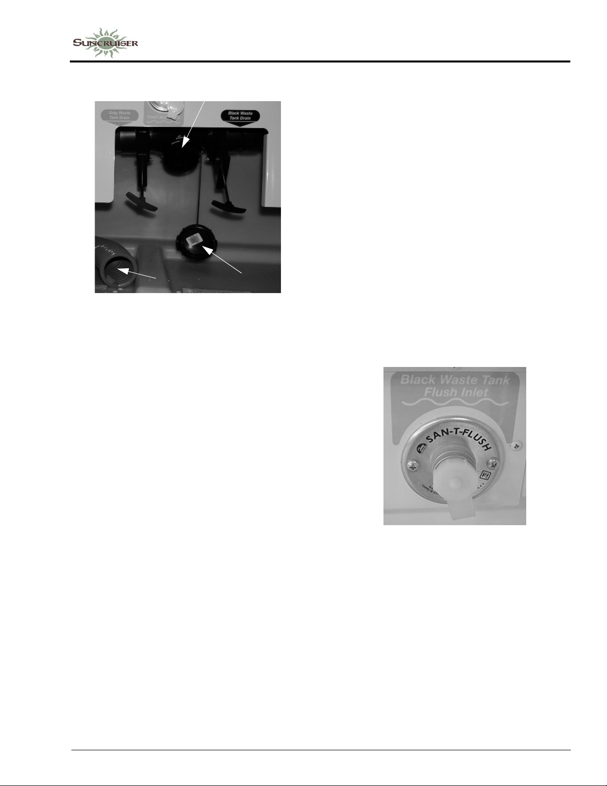
Drain Outlet
Sewer
Hose
Holding Tank Dump Valves
(Located in Water Service Center)
-Typical View
NOTE: Black and Gray Waste Tank Drain
positions may be reversed depending on
floorplan and tank location.
4. Open the Black W aste T ank Drain Valve with a quick pull and make sure there are no sags in the hose. Move the hose gently about to dislodge any waste and ensure complete drainage. Close Black Waste Tank Drain Valve as soon as tank is empty.
Dust Cap
SECTION 7 –
PLUMBING
NOTE: We recommend that you dump all
holding tanks before traveling to avoid
carrying unnecessary weight.
Flushing your Black Water Holding Tank
The black water holding tank is equipped with
an internal spray head that allows you to rinse the
inside of the tank with a shower of clean water
after dumping.
1. Dump your black water holding tank in the
usual manner at approved sewage disposal
station.
2. Leave Black Waste Tank Drain Valve open
while flushing tank.
3. Attach a garden hose from a city water
hydrant to the Black Waste Tank Flush Inlet
fitting in the water service center . (This inlet is
clearly marked separate from the City Water
inlet).
NOTE:DO NOT OPEN BOTH VALVES AT
ONCE. Do not open the gray waste tank
drain valve until the black tank is
drained and black waste tank drain valve
is closed to avoid sewage back-up into
gray tank. Gray water also rinses any
black water solids from the drain hose.
5. Open the Gray Waste Tank Drain Valve. Be sure there are no sags in the hose to ensure complete drainage. Close Gray Waste Tank Drain Valve as soon as tank is empty.
6. Add an odor control chemical to the sewage holding tank through the toilet. These chemicals are available at most RV supply centers.
7. Rinse sewer hose thoroughly with water and stow.
Black Waste Tank Flush Inlet
(Located in water service center)
-Typical View
4. Turn the water on to begin flushing. Allow water to run for about three minutes.
5. Disconnect hose from flushing system and close Black Waste Tank Drain Valve.
Using On-Site Sewer Hook-Ups
The sewer hose may remain attached to the
drain outlet and be routed out the bottom of the
compartment while the motor home is parked and
connected to an on-site sewage hook-up.
7-9
Page 84
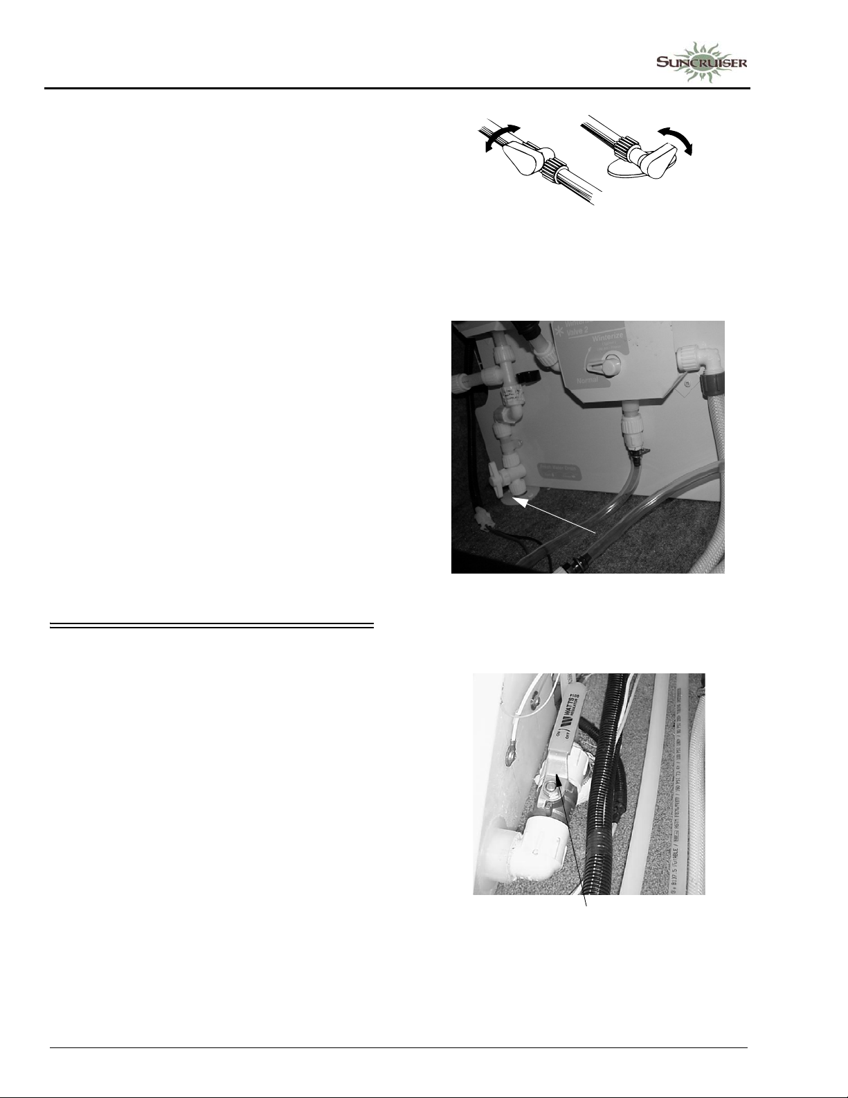
SECTION 7 –
VALVE
PLUMBING
NOTE: The drain outlet swivels downward for
better hose alignment and drainage.
Always keep service access passage
closed while utility connection is not in
use.
When using a sewer hook-up, keep the Black
and Gray Waste Tank Drain Valves closed until
a tank becomes full or when preparing to leave
the site. This keeps the solids in suspension,
allowing them to be carried out with the liquids
when the dump valve is opened. If the valve is
left open, the liquids will drain off, leaving solids
in the tank. Should this accidentally happen,
disconnect the hose, fill the tank about half full
with water, and drive a few miles to dislodge the
solids. A few starts and stops will aid in the
process. Then reconnect the hose and drain in the
normal manner.
CLOSE
DRAIN
IN-LINE
Waterline Drain Valves
-Typical
DRAIN
LINE-END
VALVE
CLOSE
Holding Tank Level Indicators
See “OnePlace® Systems Monitor Panel” in
Section 4 - Appliances and Systems for further
information on the monitor panel and checking
tank levels.
See “Specifications” in Section 1 -
Introduction for tank capacities for your model.
WATERLINE & TANK DRAIN VALVES
The water drain valves are used to drain water
from the water tank and the water supply lines
when preparing the motor home for storage or
when sanitizing the water system.
To Drain Tanks and Waterlines:
The waterline and tank drain valves are
located in an exterior compartment. Turn the
valves as indicated on the label provided,
according to the type of valve installed.
Drain valve locations are listed in the Water
System Drain Valve Locations chart at the end of
this section.
Waterline Drain Valve
-Typical View
• Open both Hot and Cold waterline valves.
• Turn water diverter valve to WATER TANK
FILL position.
Water Tank Drain Valve
-Typical View
7-10
Page 85
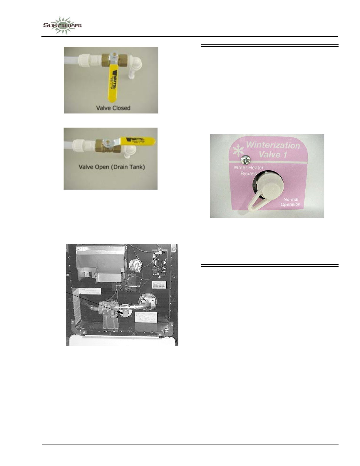
SECTION 7 –
PLUMBING
WATER HEATER BYPASS VALVE
Your coach may be equipped with a water
heater bypass valve for easier winterization of
waterlines using RV antifreeze. See Water
System Drain Valve Locations chart at the end of
this section for valve location on your model.
Turn the handle as shown to either Bypass or
Normal flow through the water heater.
Water Heater Drain Plug
The water heater drain plug is located on the
outside of the coach behind the water heater
service panel. Use a socket to remove the plug.
Drain
Plug
Water Heater Service Access
-Typical View
Leave bypass valve handle in NORMAL
FLOW position if draining water and blowing
out waterlines. Place in BYPASS position ONLY
when using antifreeze solution in waterlines.
WINTERIZING PROCEDURES
You can winterize the water and plumbing
system of your coach using one of the following
two methods – 1) Blow out waterlines using
compressed air or – 2) Fill waterlines with RV
water system antifreeze.
Method 1 – Blow Out Procedure
(Drain and purge waterlines using compressed air)
1. Level the Motor Home. If the coach is not
level, there may be “low points” in waterlines
that can trap water in the lines and prevent it
from draining properly.
2. Drain Fresh Water Tank and Waterlines.
Open all waterline drain valves and drain
fresh water tank. (See “Water System Drain
Valve Locations” chart at end of this section
for locations of drain valves on your model).
7-11
Page 86
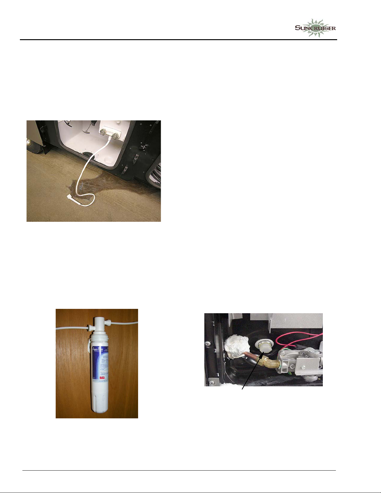
SECTION 7 –
PLUMBING
3. Drain Exterior Shower/Wash Station.
Open exterior shower knobs and lay shower
head on ground as shown to drain any water
left in the shower line. Also place the tip of
your finger into the city water inlet and gently
press the backflow valve “button” in the
center of the inlet to drain any water trapped in
the inlet line.
Using Exterior Shower to drain waterline
-Typical View
4. Remove the Water Filter Cartridge (if
equipped). Remove the filter cartridge from
the filter assembly below the galley sink.
(If your coach is not equipped with a filtered
water faucet or ice maker , pr oceed to the next
numbered step).
• Twist the filter cartridge counter-clockwise
(left) about a quarter-turn and pull it down and
out of the filter socket.
NOTE: The water filter head has a built-in
bypass. No separate diverter plug is
needed.
5. Open Faucets. Turn on the water pump and open all sink faucets and shower head knobs. Leave open after water stops flowing.
6. Drain Toilet. Press the toilet flush pedal (or electric wall switch, if your coach is equipped with an electric flush toilet) and hold until water stops flowing in the toilet. Then turn water pump switch off.
7. Drain Optional Appliances. At this time, if
your coach is equipped with an optional
refrigerator ice maker, dishwasher, or washer/
dryer, the waterlines for these appliances must
also be drained.
(See “Winterizing Optional Appliances”
instructions at the end of this section.)
If not, proceed to the next numbered step.
8. Drain Water Heater. Turn off the water
heater power switch before draining the water
heater tank to avoid damage to the heating
element. Drain the water heater by removing
the plug from the base of the water heater tank,
accessible from the outside of the coach.
(Requires socket and ratchet).
7-12
Filtered Water Faucet/Ice Maker
Filter Assembly
(Located below galley sink)
Water Heater Drain Plug
(Remove with socket)
Also open the Pressure-Temperature Relief
Valve at the top right portion of the tank to
prevent air locking in the tank while draining.
Page 87
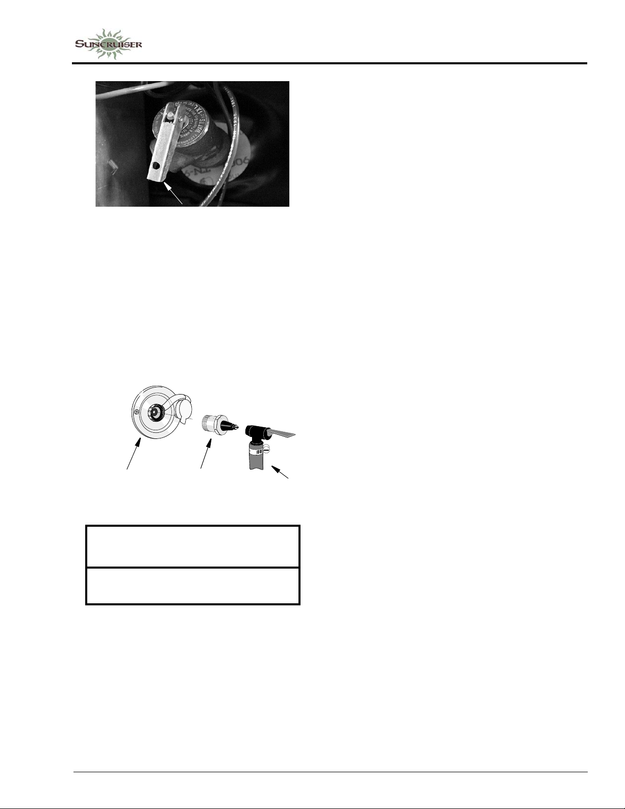
Pressure-Temperature Relief Valve
(Lift handle only when water heater is cold)
9. Connect Air Pressure. After water has
stopped draining at all faucets and drain
valves, leave faucets open and connect a
“blow-out” plug to the city water connection
on the coach. Then use a compressed air hose
regulated to 30 psi or less to force air through
the system. A blow-out plug can be purchased
at any Winnebago® or Itasca® dealer.
City Water
Connection
SECTION 7 –
PLUMBING
12. Turn air pressure off. Disconnect water
purge adapters. Recap the city water inlet to
avoid contamination by dirt or insects.
After Disconnecting Air Pressure
13. Close all waterline and tank drain valves and all faucets to avoid contamination by dirt, insects, or rodents.
14. Reinstall the Water Heater drain plug and close the P-T Relief Valve.
15. Pour about one cup of RV antifreeze down each drain for the galley sink, lavatory sink, and shower/tub. This fills the drain trap pipes to prevent holding tank odors from entering the coach during storage.
NOTE: It is not necessary to add antifreeze to
the toilet since the flush valve will be
closed.
Do not add automotive antifreeze or
caustic chemicals such as bleach or
laundry detergents into the toilet bowl or
holding tanks. Although these products
may have a deodorizing effect, they may
damage plastic and rubber parts in the
system.
Fresh Water
Inlet
Blow-out
Plug
Air Hose
NOTICE
Limit air pressure to 30 psi to avoid
damage to equipment.
NOTE: DO NOT burst air into the system. This
can damage the water pump. It is better
to let air in slowly.
10. Let air flow for five minutes until water is
completely drained out of faucets and drain
valves. Then close faucets one at a time.
11. Drain Toilet. Operate and hold toilet flush
lever (or electric wall switch, if your coach is
equipped with an electric flush toilet) until
water is completely drained from toilet.
16. Empty the water pump strainer filter bowl to avoid water freezing and cracking the filter bowl. See “Water Pump” previously in this section.
Dump and Clean Holding Tanks
17. Completely drain the sewage and waste water holding tanks at an approved waste disposal site. Drain the sewage tank first so the following waste water can rinse any waste solids from the dump outlet and sewer hose.
18. Flush the sewage tank using the Black W aste Tank Flush Inlet (if equipped).
19. Close dump valves and refit the dust cap onto the drain outlet. This will inhibit rust formation on valve shafts and prevent entry and contamination by airborne debris, insects, and rodents.
7-13
Page 88
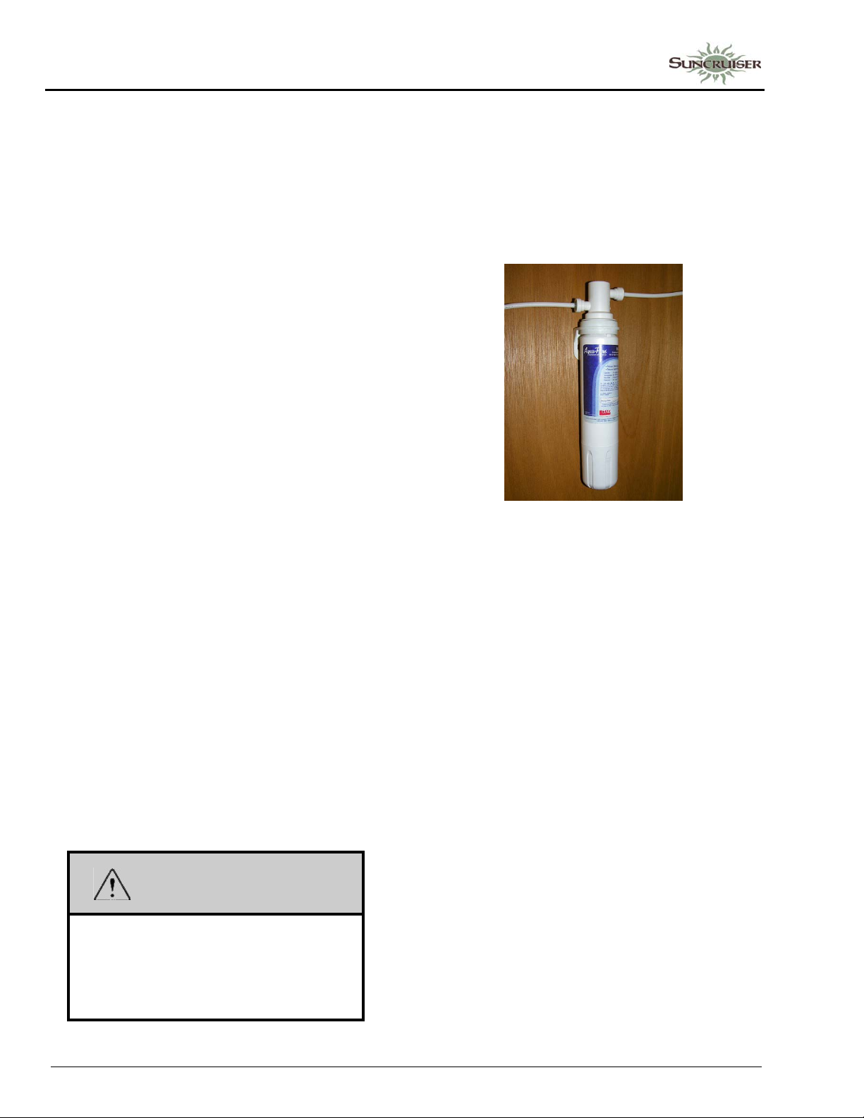
SECTION 7 –
PLUMBING
Your drainage and fresh water systems are now
totally winterized.
See instructions for removal from storage in
Section 11 - Maintenance and Storage.
Method 2 – Antifreeze Fill Procedure
(Fill plumbing lines with RV water system antifreeze)
NOTE: As an alternative to totally draining the
waterlines, you may winterize tanks and
lines by filling them with non-toxic RV
water system antifreeze through the
plumbing system.
This product is available from your
dealer and from most RV supply stores
and national retail outlets.
Follow directions on the container to
determine the correct amount to use for
your coach.
Your coach is equipped with a manually
operated waterline winterization system for your
convenience in winterizing fresh waterlines.
The system features a winterization (diverter)
valve with siphon tube to draw non-toxic RV
water system antifreeze into the waterlines.
There is also a water heater bypass valve to avoid
filling the water heater with antifreeze. See the
Drain Valve Location chart at the end of this
section for locations on your coach.
Leave bypass valve handle in NORMAL
FLOW position if draining water and blowing
out waterlines. Place in BYPASS position ONLY
when using antifreeze solution in waterlines.
Remove Water Filters (if equipped)
1. Remove and discard the filter cartridge from
the filtered water faucet/ice maker filter
assembly (if equipped) below the galley sink.
(If your coach is not equipped with a filtered
water faucet or ice maker , pr oceed to the next
numbered step).
Water Filter Assembly
(Located below galley sink)
• Twist the filter cartridge counter-clockwise
(left) about a quarter-turn and pull it down and
out of the filter socket.
NOTE: The water filter head has a built-in
bypass. No separate diverter plug is
needed.
Set Up Winterization Valves
2. Turn Winterization V alve 1 to “Water Heater Bypass” position to avoid filling water heater with antifreeze.
WARNING
NEVER use automotive antifreeze/
coolant in your RV water system. Auto
antifreeze contains ethylene glycol which,
if ingested, can cause blindness and can
be fatal.
7-14
Page 89
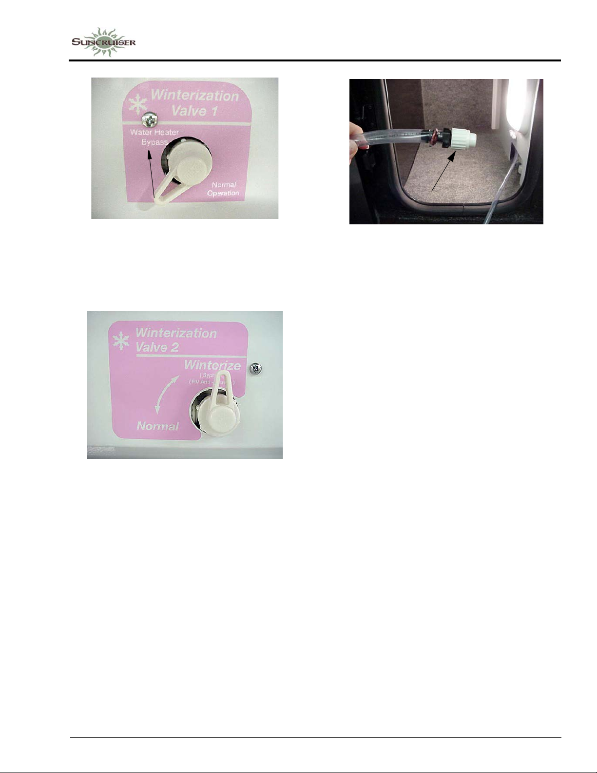
SECTION 7 –
PLUMBING
.
See Water System Drain Valve
chart at the end of this section for
location on your coach
3. Place handle of Winterization Valve 2 in the “Winterize” position.
See Water System Drain Valve
chart at the end of this section for
location on your coach
4. Remove and save the protective cap from the end of the antifreeze siphon tube (which connects to Winterization Valve 2). Insert the end of the siphon tube into a pail or other container with 2 to 3 gallons of non-toxic R V antifreeze solution.
.
RV Antifreeze Siphon Tube
(See Water System Drain Valve chart at the
end of this section for location on your coach)
-Typical View
• Insert into container of RV water system
antifreeze
Fill Lines
5. Turn the water pump switch on.
6. Open each hot and cold water faucet handle/ knob in the coach – one at a time each in turn until antifreeze solution just begins to flow from the faucet, then close. Do not forget exterior shower/wash station knobs (if equipped).
7. Press the toilet flush pedal (or electric wall switch, if your coach is equipped with an electric flush toilet) and hold until antifreeze begins flowing into the toilet. Leave small amount of antifreeze that remains in the bowl.
When Done Adding RV Antifreeze
8. Turn water pump switch off.
9. Turn the Winterization V alve 2 to “Normal”. This will stop the flow from the antifreeze siphon tube and revert the tank line flow to the pump.
10. Replace the protective cap onto the end of the antifreeze siphon tube to keep out insects and debris when not in use.
Drain Water Heater
11. Turn off the Water Heater power switch before draining the water heater tank to avoid damage to the heating element.
7-15
Page 90
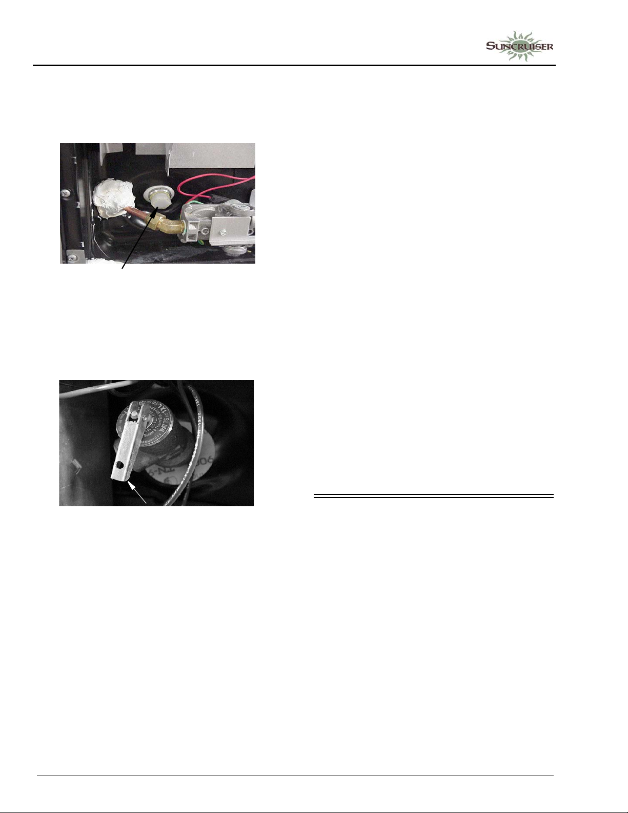
SECTION 7 –
PLUMBING
• Drain the water heater by removing the plug
from the base of the water heater tank,
accessible from the outside of the coach.
(Requires socket and ratchet).
Water Heater Drain Plug
(Remove with socket)
• Also open the Pressure-Temperature Relief
Valve at the top right portion of the tank to
prevent air locking in the tank while
draining.
Close All Drain Valves
13. Close all waterline drains and tank drain valves to avoid contamination by dirt, insects, or rodents.
14. Pour about one cup of RV antifreeze down each drain for the galley sink, lavatory sink, and shower/tub. This fills the drain trap pipes to prevent holding tank odors from entering the coach during storage.
Dump and Clean Holding Tanks
15. Completely drain the sewage and waste water holding tanks at an approved waste disposal site. Drain the sewage tank first so the following waste water can rinse any waste solids from the dump outlet and sewer hose.
16. Flush the sewage tank using the Black W aste Tank Flush Inlet (if equipped).
17. Close dump valves and refit the dust cap onto the drain outlet. This will inhibit rust formation on valve shafts and prevent entry and contamination by airborne debris, insects, and rodents.
Your drainage and fresh water systems are now
totally winterized.
Pressure-Temperature Relief Valve
(Lift handle only when water heater is cold)
• Reinstall the water heater drain plug and
close the P-T Relief Valve when drained.
Drain Appliances
12. At this time, if your coach is equipped with an
optional refrigerator ice maker, dishwasher , or
washer/dryer, the waterlines for these
appliances must also be drained. (See
“Winterizing Optional Appliances”
instructions at the end of this section.)
If not equipped with optional appliances,
proceed to the next numbered step.
See instructions for removal from storage in
Section 11 - Maintenance and Storage.
WINTERIZING OPTIONAL APPLIANCES
Winterizing Ice Maker
–If Equipped
®
Norcold
1. Drain coach waterlines.
2. Unscrew the water supply line from the
bottom of the water inlet valve and drain any
water left in the line. This connection is
located in the refrigerator service access
compartment on the outside of the coach (see
“Refrigerator Service Access Compartment”
in Section 4 - Appliances and Systems).
Refrigerator
7-16
Page 91
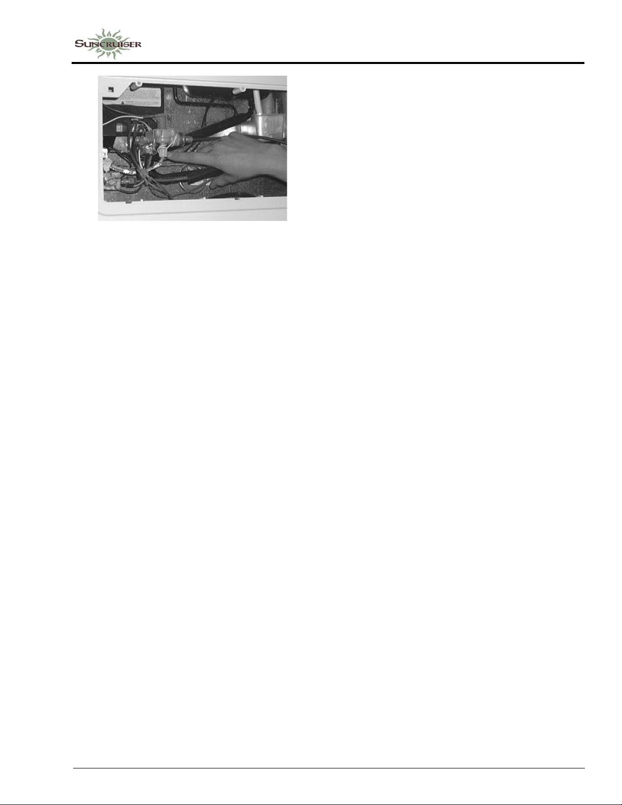
Ice Maker Water Supply Connection
(Located in refrigerator service access
compartment on outside of coach)
-Typical View
3. Let the Ice Maker run through a cycle, then raise the wire shut-off arm to the OFF position.
4. Ensure water has drained from the Ice Maker supply line, then reconnect to inlet valve.
5. Ice Maker is now winterized.
T o use Ice Maker again after seasonal storage:
1. Flush antifreeze from the waterlines (if antifreeze fill winterization procedure was performed).
2. Close all drain valves.
3. Turn the water supply ON.
4. Ensure the ice bin is in place and the wire shutoff arm is lowered to the ON position.
5. Let the refrigerator cool down to ice making temperature. Remember, this can take up to 24 hours.
6. Let the Ice Maker cycle and dump the first batch of ice.
Winterizing Washer/Dryer (Stackable)
Models ARWXF129W and ARXL129WSP
–If Equipped
Method 1 – Drain Water
If you have decided to completely drain the
coach waterlines, follow these steps to winterize
your Washer/Dryer:
SECTION 7 –
PLUMBING
1. With the Washer/Dryer power OFF , pour 1/2 quart of RV-type antifreeze into the Washer drum.
2. Close door. Advance Cycle Selector to “B”.
3. Press ON/OFF button, then press ST AR T . Let the Washer/Dryer run for 1 to 2 minutes.
4. Press ON/OFF button to turn power OFF.
5. Unplug Washer/Dryer from electrical outlet (or disconnect power).
6. Turn Water Supply Faucets OFF . Disconnect inlet hoses from faucets.
7. Drain remaining water from hoses. Finished.
To use Washer/Dryer again after seasonal storage:
1. Reconnect water inlet hoses to corresponding HOT/COLD faucets. Turn faucets ON.
NOTE: Check water inlet hoses and pump
periodically (see manufacturer’s user
guide for further information).
2. Plug Washer/Dryer into electrical outlet (or reconnect power).
3. With Washer/Dryer power OFF, pour 1/2 TBSP. of powder detergent (or liquid equivalent) into “Compartment 2” inside Dispenser Drawer.
4. Advance Cycle Selector to:
• “Position 4” (Model ARWXF129W)
• “Position 9” (Model ARXL129WSP)
5. Press ON/OFF button, then press START.
6. Allow machine to run through the complete cycle to clean out any remaining antifreeze. Finished.
Method 2 – Fill with RV Antifreeze
If you have decided to fill the coach waterlines
with RV antifreeze, follow these steps to
winterize your Washer/Dryer:
1. With machine power OFF, advance Cycle
Selector to “Position 3”.
2. Press ON/OFF button, set water temperature
to WARM*, then press START. Let machine
fill until the drum turns (this could take up to
1 to 2 minutes).
* Set water temperature to warm on Model
ARWXF129W only.
7-17
Page 92

SECTION 7 –
PLUMBING
3. Press ON/OFF button to turn power OFF.
4. Advance Cycle Selector to “B”.
5. Press ON/OFF button, then press START.
6. After letting antifreeze drain completely from drum, press the ON/OFF button to turn power OFF. Finished.
To use Washer/Dryer again after seasonal storage:
1. Reconnect water inlet hoses to corresponding HOT/COLD faucets. Turn faucets ON.
NOTE: Check water inlet hoses and pump
periodically (see manufacturer’s user
guide for further information).
2. Plug Washer/Dryer into electrical outlet (or reconnect power).
3. With Washer/Dryer power OFF, pour 1/2 TBSP. of powder detergent (or liquid equivalent) into “Compartment 2” inside Dispenser Drawer.
4. Advance Cycle Selector to:
• “Position 4” (Model ARWXF129W)
• “Position 9” (Model ARXL129WSP)
5. Press ON/OFF button, then press START.
6. Allow machine to run through the complete cycle to clean out any remaining antifreeze. Finished.
Winterizing Washer/Dryer (Combination)
–If Equipped
Method 1 – Drain Water
If you have decided to completely drain the
coach waterlines, follow these steps to winterize
your Washer/Dryer:
1. With the Washer/Dryer power OFF, pour 1/2
quart of RV-type antifreeze into the Washer
drum.
2. Close door . Advance Cycle Selector to SPIN.
3. Press ON/OFF button, then press ST AR T. Let
the Washer/Dryer run for 1 to 2 minutes.
4. Press ON/OFF button to turn power OFF.
5. Unplug Washer/Dryer from electrical outlet
(or disconnect power).
6. Turn Water Supply Faucets OFF . Disconnect inlet hoses from faucets.
7. Drain remaining water from the hoses. Finished.
To use Washer/Dryer again after seasonal storage:
1. Reconnect water inlet hoses to corresponding HOT/COLD faucets. Turn faucets ON.
NOTE: Check water inlet hoses and pump
periodically (see manufacturer’s user
guide for further information).
2. Plug Washer/Dryer into electrical outlet or reconnect power supply.
3. With Washer/Dryer power OFF, pour 1/2 TBSP. of powder detergent (or liquid equivalent) into “Compartment 2” inside Dispenser Drawer.
4. Advance Cycle Selector to “Position 9”.
5. Press ON/OFF button, then press START.
6. Allow machine to run through the complete cycle to clean out any remaining antifreeze. Finished.
Method 2 – Fill with RV Antifreeze
If you have decided to fill the coach waterlines
with RV antifreeze, follow these steps to
winterize your Washer/Dryer:
1. With machine power OFF, turn Wash Temp
knob to HOT.
2. Advance Cycle Selector to “Position 3”.
3. Press ON/OFF button, then press ST AR T . Let
machine fill until the drum turns (this could
take up to 1 to 2 minutes).
4. Press ON/OFF button to turn power OFF.
5. Advance Cycle Selector to SPIN.
6. Press ON/OFF button, then press START.
7. After letting antifreeze drain completely from
drum, press the ON/OFF button to turn power
OFF. Finished.
To use Washer/Dryer again after seasonal storage:
1. Reconnect water inlet hoses to corresponding
HOT/COLD faucets. Turn faucets ON.
7-18
Page 93
SECTION 7 –
PLUMBING
NOTE: Check water inlet hoses and pump
periodically (see manufacturer’s user
guide for further information).
2. Plug Washer/Dryer into electrical outlet or reconnect power supply.
3. With Washer/Dryer power OFF, pour 1/2 TBSP. of powder detergent (or liquid equivalent) into “Compartment 2” inside Dispenser Drawer.
4. Advance Cycle Selector to “Position 9”.
5. Press ON/OFF button, then press START.
6. Allow machine to run through the complete cycle to clean out any remaining antifreeze. Finished.
WATER SYSTEM DRAIN VALVE LOCATIONS
SYSTEM DRAIN VALVE LOCATION
Waterline Drain Valves: • Models 32H and 35P: Compartment behind entrance door.
• Model 37F: Compartment rear of right-hand rear wheel lip.
Water Tank Drain Valves: • Compartment rear of right-hand rear wheel lip.
W ater Heater Drain: • Drain plug on outside of coach behind service door . Use socket
to remove drain plug.
Winterization Valve 1:
(Water Heater Bypass)
• Models 32H and 35P: Bypass valve is located in the utility
compartment on the passenger side of the coach.
• Model 37F: Compartment rear of right-hand rear wheel lip.
Winterization Valve 2:
(Antifreeze Siphon)
• Models 32H and 35P: Valve with clear vinyl siphon tube is
located in the utility compartment on the passenger side of the
coach.
• Model 37F: Compartment rear of right-hand rear wheel lip.
7-19
Page 94

Page 95
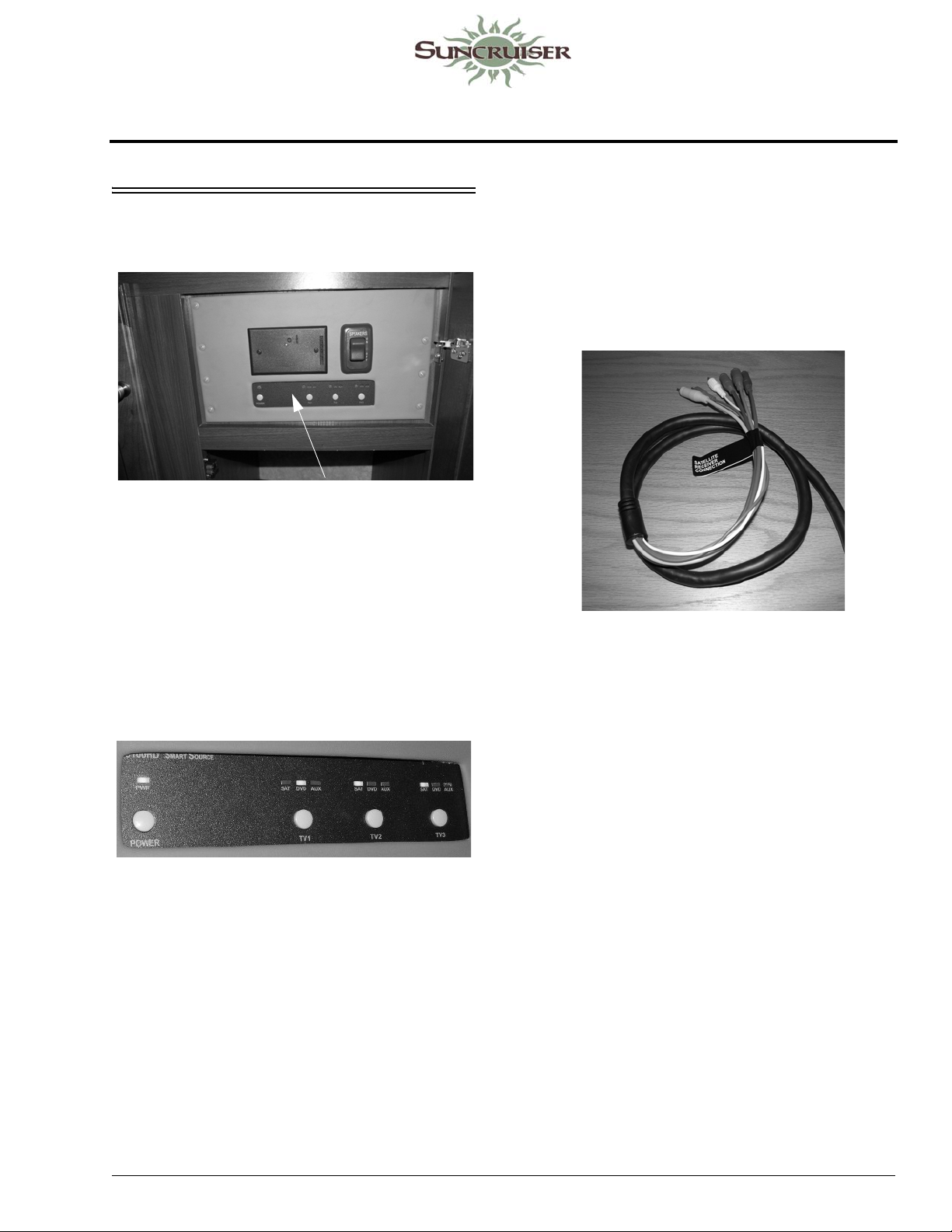
SECTION 8 – ENTERTAINMENT
HIGH DEFINITION VIDEO SELECTION SYSTEM
High Definition Video Selection Box
-Typical View
The Video Selection System allows you to
watch standard or high definition video from
multiple sources on multiple TV’s at the same
time. You can select either DVD, Satellite, or
Auxiliary AV Component.
TV’s connected to this system are the main
TV, 2nd main TV (if equipped), and the exterior
entertainment center TV (if equipped).
The TV will display the DVD logo when the
correct input is selected.
To Watch Satellite TV (Dish)
-If Equipped
• Connect satellite receiver to accessory
connection cables (provided in the prep area).
Accessory Connection Cables
• Power “ON” TV and the High Definition
Video Selection Box.
• Determine which TV you want to use (e.g.
TV1 for main TV) and select “SAT” from the
High Definition Video Selection Box.
To Watch DVD
• Power “ON” TV and the High Definition
Video Selection Box.
• Power “ON” the DVD player.
• Determine which TV you want to use (e.g.
TV2 for second main TV) and select “DVD”
from High Definition Video Selection Box.
• On TV remote control, press INPUT or
SOURCE button and select either
COMPOSITE (for standard definition) or
COMPONENT (for high definition).
• On TV remote control, press INPUT or
SOURCE button and select either
COMPOSITE (for standard definition) or
COMPONENT (for high definition).
The TV will display the satellite logo when
the correct input is selected.
To Watch Broadcast TV (Antenna)
• Power “ON” the TV Signal Amplifier Power
Switch. All TV’s in the coach will now be
connected to the roof antenna (via coax cable)
and set TV to be viewed through antenna
input.
8-1
5 - DASH / AUTO
Page 96
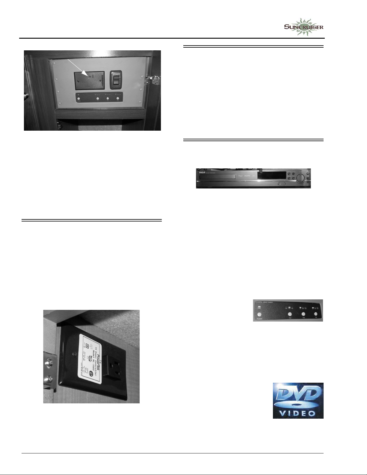
SECTION 8 –
ENTERTAINMENT
TV Signal Amplifier Power Switch
-Typical View
To Watch Cable TV
• Power “OFF” the TV Signal Amplifier Power
Switch. All TV’s in the coach will now be
connected to the cable TV (via coax cable)
and set TV to be viewed through cable TV
input.
FRONT TV IGNITION SWITCH INTERLOCK
–If Equipped
If your coach is equipped with a front
overhead TV, it is plugged into a special
electrical outlet with a built-in ignition switch
interlock. The device allows the front overhead
TV to operate only when the ignition key is in the
Off or Accessory positions.
AUDIO-VIDEO SYSTEM BASIC OPERATION
NOTE: For your convenience, we have also
included a handy, tear -out version of this
“A/V System Basic Operation” guide in
Section 8 of your Operator’s Manual
Supplement.
See your InfoCase for specific operating
guides for audio and video components.
DVD HOME THEATER SYSTEM
–If Equipped
The available DVD home theater system
operates from 120-volt AC household current
only, so you must have either the shoreline
connected, the generator running, or the inverter
turned on (if equipped).
The TV is connected to the Home Theater
System, which plays through theater speakers in
the lounge area of the coach.
Set TV Video Input
• Turn ON the TV, DVD player, and Video
Selection Box.
NOTE: Switch the
V ideo Selection
box to DVD for
the TV that you
are going to use).
• Press INPUT/SOURCE
button on the remote or
front of TV and select the
DVD input (Video 1 or
Component) on the TV.
8-2
Front TV Ignition Switch Interlock
-Typical View
The TV screen will
display the DVD player logo
when the correct input is
selected.
Page 97
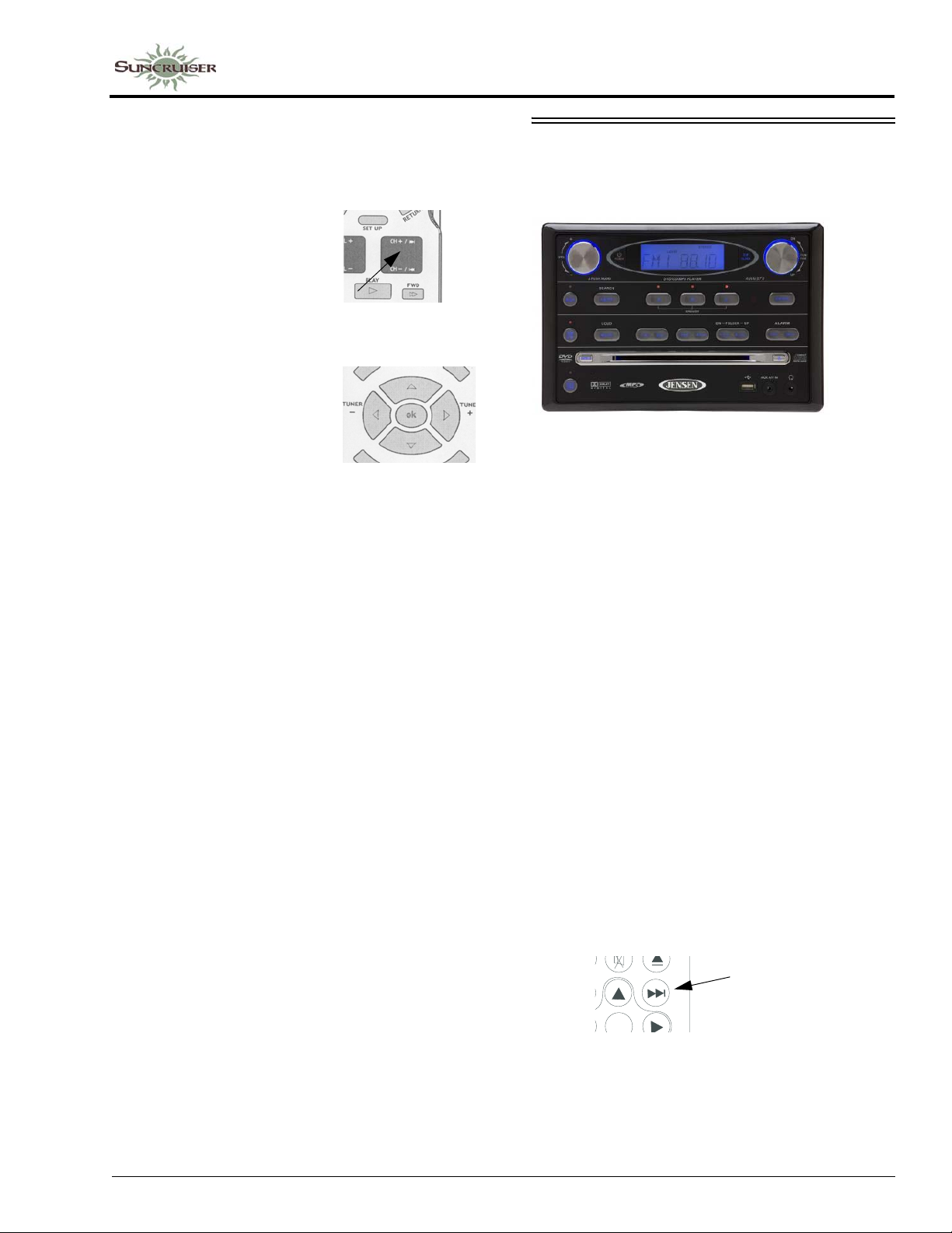
Play DVD with Theater Sound
• Insert DVD into player. DVD will begin to
load automatically. TV screen will typically
show “READING” or “LOADING.”
• The DVD may load directly
to the main title/menu
screen or it may begin to
play previews. Y ou may be
able to skip previews if
desired by pressing the NEXT (CH+ / CH-)
button until you see the main menu screen.
• When the main menu
screen appears, use the
arrow buttons on the
remote to select the desired
entry or press the OK or
PLA Y buttons on the remote (or “Play” button
on DVD player) to begin playing the feature.
• Volume is adjusted with the DVD remote (or
volume control on DVD player).
SECTION 8 –
ENTERTAINMENT
CD/DVD PLAYER - BEDROOM
(& Stereo Radio Alarm Clock)
–If Equipped
The TV operates from 120-volt AC household
current only, so you must have either the
shoreline connected, the generator running, or the
inverter turned on (if equipped).
The DVD player is connected to the TV and
plays through the TV stereo speakers.
TV Sound Through Home Theater Speakers
When watching TV programs (broadcast,
cable, or satellite), the TV normally plays sound
through its own built-in stereo speakers. To
connect TV sound output to home theater
speakers for a richer sound quality, follow these
steps:
• Turn the TV and DVD player ON.
• Select the TV channel you wish to watch.
• Press FUNCTION button on DVD player or
remote to set DVD player to “AV IN.”
• Use the TV Menu button to turn TV speaker
on or off, or if available, change audio output
to “V ariable Audio Output.” (See TV owner’s
manual for instructions.) This will route TV
stereo sound output through the home theater
system.
• Select TV channels to watch and adjust
theater speaker volume with remote for either
the TV or DVD.
NOTE: T urn the volume level up significantly on
the DVD player when using the home
theater as an amp for the TV through the
stereo system.
Set TV Video Input
• Turn TV and DVD player ON.
• Press the SOURCE or INPUT button on the
TV or TV remote to select INPUT1 or AV1.
• The TV screen will display the DVD player
logo when the correct input is selected.
Play DVD
• Insert DVD into player. DVD will begin to
load automatically. TV screen will typically
show “READING” or “LOADING”.
• The DVD may load directly to the main title/
menu screen or it may begin to play previews.
Y ou may be able to skip previews if desired by
pressing the NEXT button until you see the
main menu screen.
NEXT
ENTER
• When the main menu screen appears, use the
arrow buttons on the DVD remote to select the
desired entry or press the ENTER or PLAY
buttons on the remote (or “Play” button on
DVD player) to begin playing the feature.
8-3
Page 98
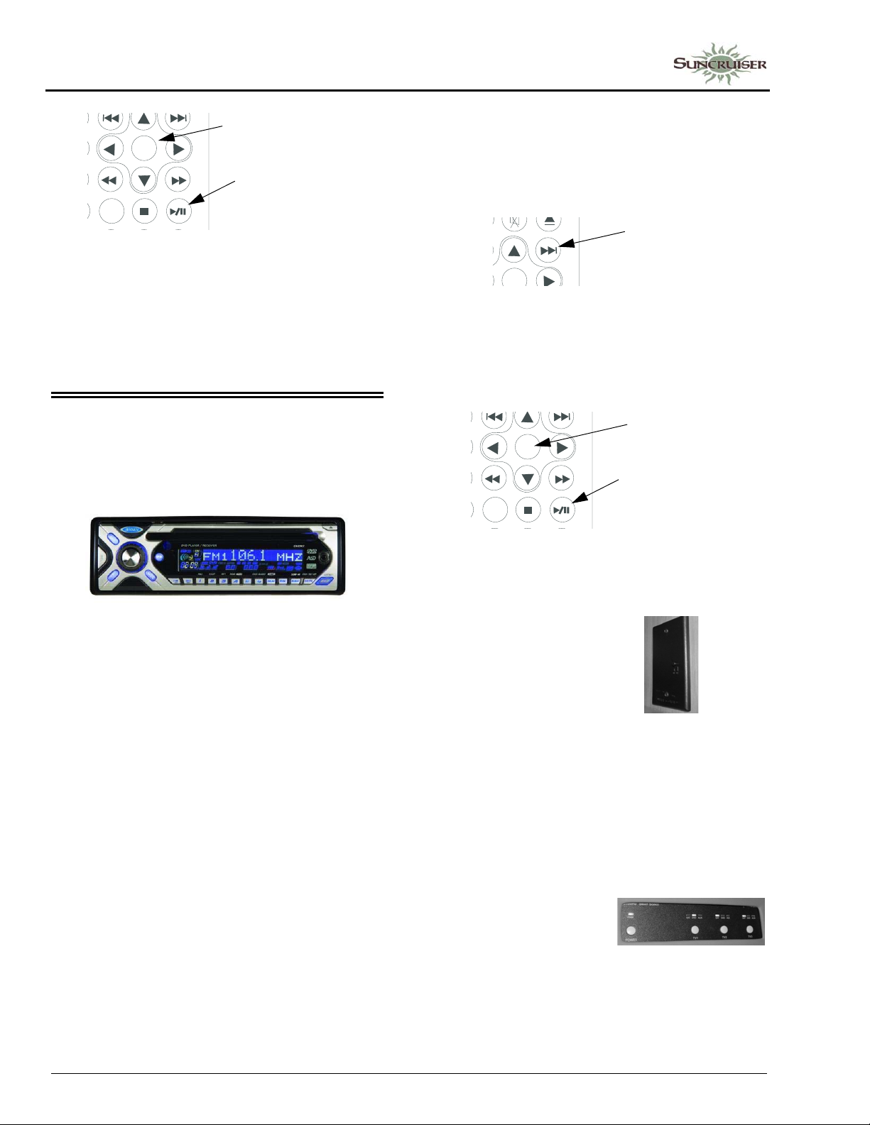
SECTION 8 –
ENTERTAINMENT
ENTER
ENTER
PLAY/PAUSE
T/F
• Volume is adjusted with the DVD remote or
volume buttons on DVD player.
Further Information
For further information and operating
instructions, see the manufacturer’s user guide
provided in your InfoCase.
• The DVD may load directly to the main title/
menu screen or it may begin to play previews.
Y ou may be able to skip previews if desired by
pressing the NEXT button until you see the
main menu screen.
NEXT
ENTER
• When the main menu screen appears, use the
arrow buttons on the DVD remote to select the
desired entry or press the ENTER or PLAY
buttons on the remote (or “Play” button on
DVD player) to begin playing the feature.
CD/DVD PLAYER
(& Stereo Radio)
Exterior Entertainment Center
–If Equipped
The TV operates from 120-volt AC household
current only, so you must have either the
shoreline connected, the generator running, or the
inverter turned on (if equipped).
The exterior entertainment center TV is
connected to the exterior DVD player, video
selection box, the rooftop antenna, and the park
cable input.
Play DVD
• Turn TV and DVD player On.
• Press the SOURCE or INPUT button on the
TV or TV remote to select INPUT 2 or AV2.
• The TV screen will display the DVD player
logo when the correct input is selected.
• Insert DVD into player. DVD will begin to
load automatically. TV screen will typically
show “READING” or “LOADING”.
ENTER
ENTER
PLAY/PAUSE
T/F
• Volume is adjusted with the DVD remote (or
volume buttons on DVD player).
Antenna
• Turn On antenna booster
inside coach.
• Turn On TV and tune to
desired channel.
Cable
(Park cable input located in power cord compartment)
• Turn Off antenna booster inside coach. See
above photo.
• Turn On TV and tune to desired channel.
Video Programming from the V ideo Selection Box
• Turn On video
selection box and
select desired input
(Satellite, DVD, or
Aux) for TV2.
• Turn On TV and press the SOURCE or
INPUT button on the TV or TV remote to
select INPUT1 or AV1.
8-4
Page 99
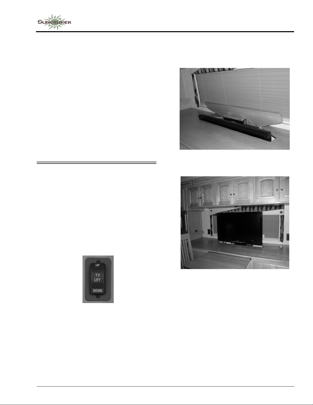
SECTION 8 –
ENTERTAINMENT
Play TV Through Stereo Speakers
The exterior entertainment center TV is
connected to the video selection box, the rooftop
antenna, and the park cable input. To play this
signal through the stereo speakers:
• Tune TV to desired channel or input.
• Turn On the radio and press the MODE button
on the remote or the radio until it displays AV IN1.
• Adjust the volume on the TV or the radio for
desired level.
Further Information
For further information and operating
instructions, see the manufacturer’s information
included in your InfoCase.
TV (DINING BUFFET) - POWER LIFT
–If Equipped
Your coach may be equipped with a TV power
lift/lower mechanism built into the dining buffet
which allows you to raise and lower the TV with
a touch of a switch.
The control switch is located on the galley end
near the buffet. Some models are equipped with
an additional control switch located on the
bottom of the sofa/lounge chair overhead.
Power Lift Operation
1. To raise the TV, press the control switch UP and the TV will pop up through the access lid.
2. Continue to raise TV to the height that best suits your viewing needs.
Buffet TV Power Lift/Lower Control Switch
(Located on galley end near buffet)
Road vibration may damage the TV and/or
power lift mechanism in the extended position. If
you encounter significant road vibration, lower
the TV into stored position to avoid possible
property damage.
3. To lower the TV back into stored position, press the control switch DOWN. The power lift/lower mechanism will stop automatically when the TV is all the way seated into stored position.
NOTE: Ensure that the buffet counter is clear
before raising/lowering the TV to pr otect
the TV, lift/lower mechanism, and
personal property from possible damage.
8-5
Page 100
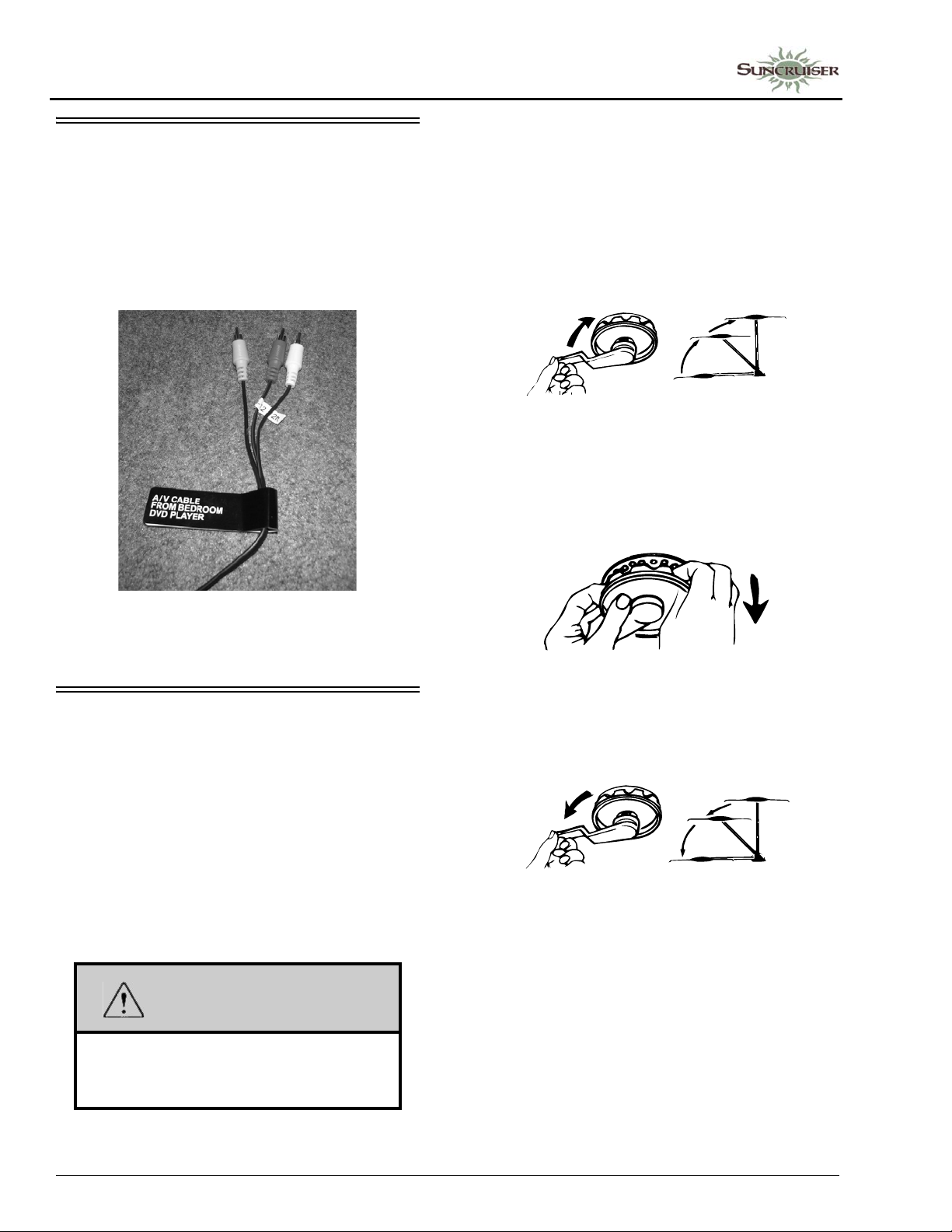
SECTION 8 –
ENTERTAINMENT
BEDROOM DVD CABLES
–If Equipped
If your coach is equipped with a bedroom TV
(but is not equipped with a bedroom DVD
player), audio/video connection cables are
provided for the TV to connect to a DVD player,
video game, or video camera.
Raising Antenna to Operating Position
Turn elevating crank clockwise in “UP”
direction until some resistance to turning is noted
(approximately 13 turns). Antenna is now in
operating position.
Turn amplifier power switch “ON” to receive TV
signal.
Rotating Antenna for Best Picture
Make sure antenna is in the “UP” position.
Pull down on directional handle using both hands
until it disengages ceiling plate and rotate for best
picture and sound on TV set.
Bedroom Audio/Video
Connection Cables
(Located near bedroom TV)
TV ANTENNA
The TV antenna on your motor home can be
easily raised, rotated a full 360° and lowered
from inside the vehicle by simply turning a crank
or directional handle. A built-in signal amplifier
designed to strengthen signals, is controlled by a
power switch built into the optional video
selection box or on a wall plate assembly.
See the antenna manufacturer’s operation,
care, and maintenance information in your
InfoCase.
WARNING
Never allow the antenna to touch
electrical power lines or any other
electrical wires.
Lowering Antenna to Travel Position
Rotate antenna until pointer on directional
handle aligns with pointer on ceiling plate.
Turn elevating crank (counter-clockwise) in
“DOWN” direction until resistance is noted
(approximately 13 turns). Antenna is now locked
in travel position. Turn amplifier power switch
“OFF”.
8-6
 Loading...