


Electronic Water Detection Device
CONTENTS
This package contains:
• 1 WB-200
• 1 Surface Probe - Unsupervised (W-S-U)
• 1 Installation/Operating Instructions Guide
WB-200
SPECIFICATIONS
Power Requirement 8-28 VDC @ 35mA
8-28 VAC @ 100mA
Sensitivity Will not alarm due to high humidity or condensation.
Operating Temp 32˚ to 130˚F (0˚ to 54˚C); non-condensing environment (indoor use only)
Output 1 Form C Relay (N.O./N.C.)
1 Amp @ 30 VDC, resistive
1 Amp @ 24 VAC, resistive
Probe Options Includes 1 Standard Unsupervised Surface Probe (W-S-U)
Accepts up to 6 Unsupervised Surface Probes (W-S-U) wired in parallel or
Accepts up to 6 Unsupervised Under Carpet Probes (W-UC-U) wired in parallel.
Max Cable Length 1-2 probes; max recommended distance of 200’ (61 m)
3-6 probes; max recommended distance of 100’ (30.5 m)
Probe Cable Probes include 15” (4.6 m) cable. Extend using 22-18 AWG twisted pair.
Console Weight 2.4 oz (0.07 kg)
Console Dimensions 4.1 x 2.36 x 1.18” (10 x 6 x 3 cm) with flanges
Probe Dimensions Surface: 2 x 3 x 0.88” (5.1 x 7.6 x 2.2 cm)
Under Carpet: 2 x 3 x 0.18” (5.1 x 7.6 x 0.5 cm)
Mounting Flanges
Case Material ABS
Warranty 1 Year Limited
Tech Support 8:00am - 5:00pm Central Time
(800) 635-4269 • +1-507-625-7231 P
www.winland.com
© 2012 Winland Electronics, Inc.
D-011-0116 Rev C (08/2012)
INTRODUCTION
WATER
WATER
WATER
WATER
Thank you for your purchase of the Winland WaterBug® model WB-200. The WB-200 is completely electronic and is designed
to detect water only (distilled and deionized water cannot be detected). The WB-200 is not a self contained warning device.
For proper operation, it must be used in conjunction with an alarm system, sounder, etc. It is designed so that the control
console mounts on a wall or other flat vertical surface and the remote probes are placed in the locations where water
leakage is most probable. Up to six remote probes may be connected to one control console. A film of moisture forming a
bridge between the two metallic contacts on any remote probe is all that is needed for the unit to signal an alarm condition.
The output on the WB-200 is non-latching, but will remain in alarm state until the moisture bridge is broken. As sensitive
as the WB-200 is, it will not alarm due to high humidity or condensation. The WB-200 is ideal for use in homes, offices,
computer rooms, warehouses, etc.
INSTALLATION
Locate the area where the WB-200 console is to be mounted. Using the WB-200 as a guide, mark the two locations on the
mounting surface where the holes will be drilled in order to use the case’s mounting flanges. If mounting on drywall, use the
two provided drywall anchors. Once the holes have been drilled, place the WB-200 against the sur face and drive the screws
into the holes or anchors.
Multiple probes must be hooked up in parallel to the two “sensor” terminals. The remote surface probes may be mounted
securely to the floor or a wall. Mounting the probe(s) to a ver tical surface like a wall enables you to monitor an area for rising
water levels. This is useful in basement sump pumps and other types of water storage and drainage systems.
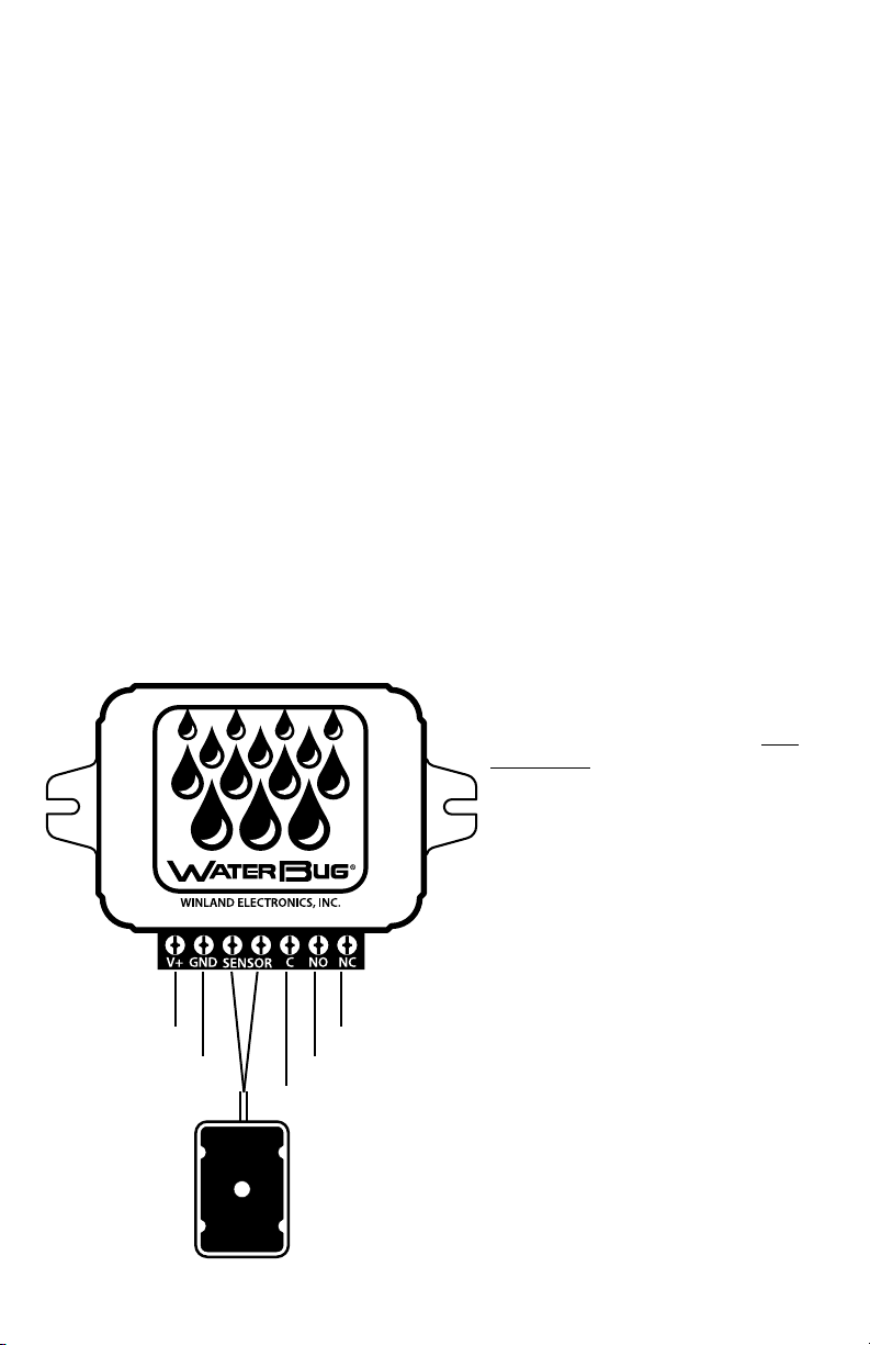
TERMINAL BLOCK CONNECTIONS
Relay contacts are accessible on the terminal block (See
Figure 1). The WB-200 is in normal condition when
power is applied and no moisture is being detected. It’s
in alarm condition when water is detected by any one
of the remote probes.
VAC / +VDC
Ground (VAC / -VDC)
Relay N.C.
Relay N.O.
Relay Common
Figure 1
Note: When connecting DC power to the WB-200 be
sure to observe polarity and test to see if the WB-200
is operating properly. This may be done by forming
a water bridge between two of the metallic contacts
located on the probe (See Figure 2) with a moistened
finger or cloth. If the WB-200 is not operating properly,
check the polarity of the power supply connections.
AC – Power input wires are interchangeable
DC – Positive to V+ and negative to Ground
 Loading...