

Powerless Temperature Monitoring with Single Output
CONTENTS
This package contains:
• One (1) TA-1
• Two (2) mounting screws and two (2) wall anchors
• Mounting template (inside this Instruction Guide)
• One (1) Installation/Operating Instructions Guide
TA-1
SPECIFICATIONS
Power Requirement No power required to operate.
Operating Temperature Alarm Use: 50 to 130° F (10 to 54° C); non-condensing environments only.
Alarm contacts may not function outside of this range.
Display Use: -30 to 130° F (-34 to 54° C); non-condensing environments only.
Low Limit Adjust Range -30 to 120° F (-34 to 49° C)
High Limit Adjust Range -20 to 130° F (-29 to 54° C)
Temp Accuracy ±3°F (±1.7° C)
Temp Response Time TC = 14 minutes
Temp Sensing Element Bimetallic Coil
Outputs Gold plated N.O. dry contacts (Not for high voltage use.)
Contact Output Rating 50mA @ 12VDC
Weight 6.5 oz (.18 kg)
Dimensions 6.25 x 3.75 x 2” (15.9 x 9.5 x 5.1 cm)
Material ABS
Mounting Key slot
Tech Support 8:00am - 5:00pm Central Time
(800) 635-4269 • +1-507-625-7231 P
www.winland.com
© 2012 Winland Electronics, Inc.
D-011-0113 Rev B (08/2012)
INTRODUCTION
®
Low Limit Arm
Lo
w Limit
Adjustmen
t
High Limit
Arm
High Limit
Adjustment
Temperature Indicato
r
1
2 3
4 5
6
7
8
9
0
Panel / Dialer / Transmitter
®
®
®
The Temp˚Alert ® has been designed for reliable monitoring of non-condensing (indoor only) environment
areas where high and low temperature limits are critical.
Select an acceptable temperature range by setting the adjustable high and low limit arms. If the monitored are
temperature either rises or falls to the limit arms, the temperature indicator will contact one of the limit arms.
This completes the circuit and provides you with a dry contact alarm signal. The TA-1 contacts are normally
open (N.O.) dry contacts rated at 50mA at 12 VDC . This output can be used to activate alarm systems, telephone
dialers, or other remote warning devices. Temp˚Alert ® is the ideal addition for any security system.
LOCATION
In specifying the location and number of TA-1s to install consider room size, effectiveness of the ventilation
system, and critical monitoring areas. If the building already has an energy management system, an easy rule
of thumb to follow is to install a TA-1 near each thermostat. It should be mounted on a wall or other vertical
surface in the area where temperature is to be monitored. Make sure it is well clear of windows, doors, or heat
sources that could cause an inaccurate reading of air temperature. When protecting a building against freeze
damage, always install at least one Temp˚Alert ® on every level of the home or business.
INSTALLATION
Items needed:
· Standard screwdriver · 11/32” wrench · 22-18 AWG twisted pair
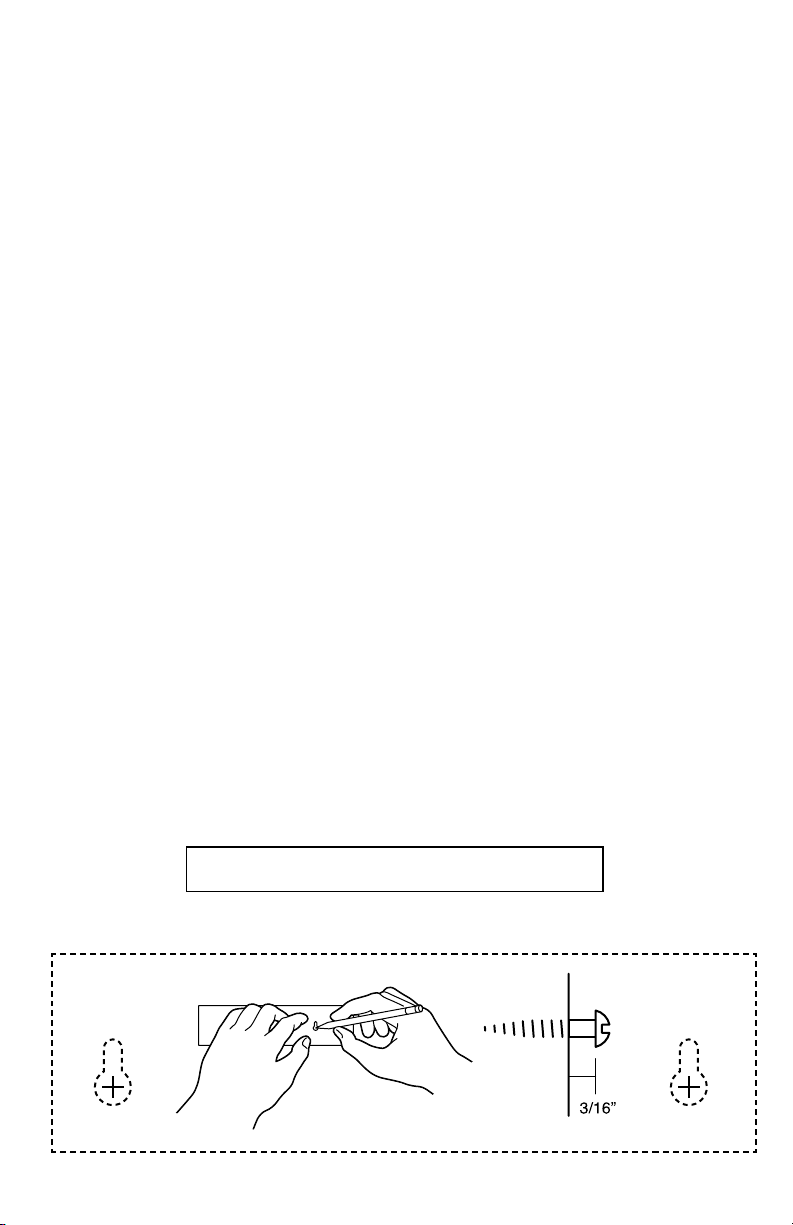
STEP 1 – ATTACH TA-1 TO MOUNTING SURFACE
Position the mounting template in the desired location and mark the mounting holes. Depending on the type
of surface you are mounting to, you may need to predrill holes to accept the mounting screws alone, or use the
plastic anchors and mounting screws. Drive the screws into the mounting surface, allowing approximately 3/16”
between the screw head and the mounting surface. (See Mounting Template below.) Engage the key slots on
the back of the TA-1 case with the screw heads and press down.
To insure proper operation, test weekly.
MOUNTING TEMPLATE
 Loading...