

Page 1
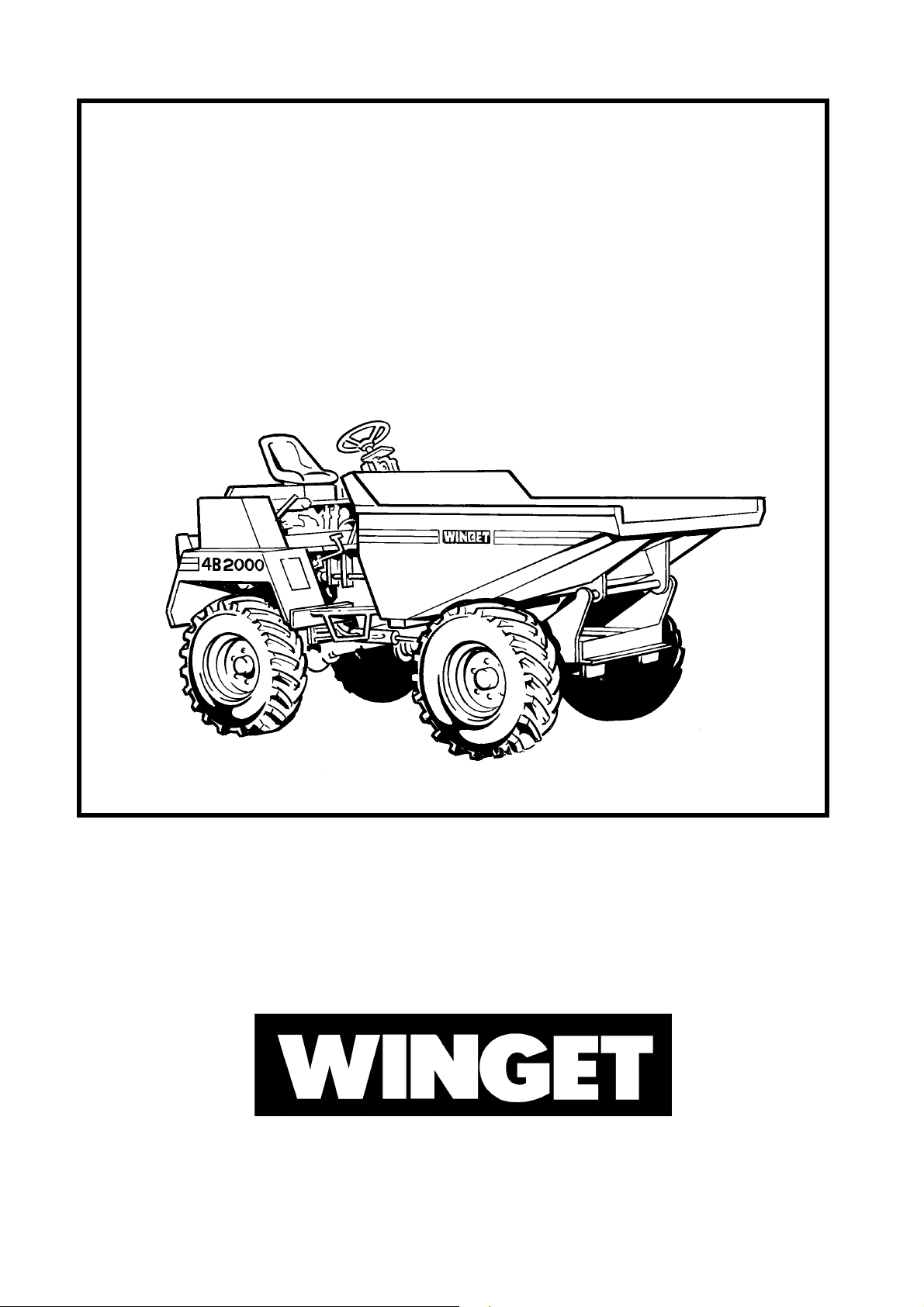
DUMPER
4B2000
OPERATORS HANDBOOK
Manual MANS524 March 2013
WINGET LIMITED, P.O. Box 41, Edgefold Industrial Estate, Plodder Lane, Bolton, BL4 0LR, England
Tel: +44 (0) 1204 854650 Fax: +44 (0) 1204 854663
E mail: [email protected], [email protected]
www.winget.co.uk
Page 2
INTRODUCTION I
Dumper
4B2000
The contents of this Handbook, although correct at the time of publication, may be
subject to alteration by the Manufacturers without notice.
Winget Limited operate a policy of continuous product development. Therefore, some
illustrations or text within this publication may differ from your machine.
Page 3

II INTRODUCTION
CONTENTS
Section Page
INTRODUCTION
Contents II
Introduction to the Handbook III
Machine identification III
Warranty Terms & Conditions IV
SAFE WORKING
Machine modification 1.1
Training 1.1
Running-in 1.1
Driving 1.1
Skips and loading 1.3
Towing 1.3
Gradients 1.3
Hydraulics 1.4
Servicing 1.4
Decal identification 1.6
OPERATION
Controls layout 2.1
Running-in a new engine 2.3
Pre-start checks 2.3
Driving the dumper 2.3
Starting and stopping the engine 2.4
Gradients 2.10
Braking 2.10
Engage gear lever 2.10
Stopping the dumper 2.10
Leaving the dumper 2.10
Skip operation 2.11
Towing 2.12
Section Page
SERVICE
Safe working 3.1
Service schedule chart 3.2
Engine 3.4
Fuel System 3.6
Air Cleaner 3.9
Gearbox 3.10
Transfer box 3.11
Propeller shafts 3.12
Battery 3.13
Hydraulic system 3.14
Greasing 3.19
Braking systems 3.20
Wheels & Tyres 3.22
Axles 3.23
TECHNICAL INFORMATION
Dimensions 4.1
Specifications 4.2
General dumper
Lubricants & fluids
Adjustments
Pressures
Tyres
Load capacities
Machine weight
Vibration declaration
Electrical circuit, without road lights 4.5
Electrical circuit, road lights 4.6
PARTS SECTION
Page 4
INTRODUCTION III
THE HANDBOOK
WARNING The Operator must read all the Handbook and fully understand its contents
before attempting to operate the machine.
THE HANDBOOK MUST NOT BE REMOVED FROM THE MACHINE.
The Handbook should be kept clean and in good condition. Additional copies of the
Handbook can be obtained from your Distributor.
The contents of this Operators Handbook are designed as a guide to the machine’s
controls, operation, working capacities and maintenance. It is not a training manual.
Only trained operators should use this machine. Consult your Distributor for details of
authorised training courses.
In this Handbook are WARNING notes. They are preceded by this symbol:
WARNING These notes are used to indicate that the procedure being described in the
Handbook must be followed to avoid serious injury or death to yourself or
others; or damage to the machine.
The warnings are also used to protect the machine from unsafe servicing
practices.
Pay particular attention to the warnings given in the Handbook.
If you have any doubts about any aspect of the machine’s capability or servicing
procedures, you must consult the manufacturer.
MACHINE IDENTIFICATION
Please record the model and serial numbers of your machine in the spaces provided and
quote them when ordering parts.
Model - Year
Dumper serial no.
Front axle
Rear axle
Key, start
Engine
Gearbox
Transfer box
Ram steering
Ram, tipping, L.H.
Ram, tipping, R.H.
Tyre manufacturer & size
Page 5

IV INTRODUCTION
WARRANTY TERMS & CONDITIONS
The Manufacturer assures you that if any part of the machine becomes defective due to
faulty manufacture or materials within 12 months from the date of purchase, the part will
be repaired or replaced under warranty free of charge by any authorised Winget
Distributor. Warranty repairs must be carried out by Winget Distributors.
This Warranty is given to the first owner and may be transferred to subsequent owners
for the balance of the Warranty period.
The Manufacturer’s liability only extends to the costs of repair or replacement of the
faulty parts and necessary labour charges involved in the repairs. The Company
accepts no liability for any consequential loss, damage or injury, resulting directly or
indirectly from any defect in the goods.
Items not covered by Warranty and considered to be the customer’s responsibility
include normal maintenance services; replacement of service items and consumables;
replacement required due to abuse, accident, misuse or improper operaton; replacement
of wearable items e.g. pins, bushes, brake linings, clutch linings etc.
The Warranty will not apply where the equipment is modified, converted, or used for
purposes other than those for which it was designed, unless clearance for the
modifications etc. have been granted by the Manufacturer, in writing.
The Pre-Delivery Inspection and Warranty Registration Document must be completed
correctly and returned to the Manufacturer within 7 days of sale date. Failure to do so
may result in the claim being subsequently rejected.
Tyres and tubes are not covered by Warranty, but are covered by the tyre
manufacturer’s own warranty system which provides against defects in material or
workmanship.
Engines are covered separately by the engine manufacturers, and engine warranty
repairs must be handled by the relevant engine manufacturers’ distrubutors.
No claim will be considered if other than genuine Winget Limited parts, which must be
obtained from Winget Limited via an authorised Distributor, are used to effect a repair, or
if lubricants other than those recommended by Winget Limited are used.
The equipment must be serviced in accordance with the service schedules laid down by
Winget Limited. Evidence that these have been complied with may be required before
Warranty Claims are reimbursed.
The Manufacturer’s policy is one of continuous improvement. Winget Limited reserve the
right to change specifications without notice. No responsibility will be accepted for
discrepancies which may occur between specification of machines and the descriptions
contained in publications.
Page 6
SAFE WORKING 1.1
Safety is the responsibility of all persons working with this machine. Think
“safety” at all times. Read and remember the contents of this handbook.
The safe working recommendations for specific tasks are found with the
instructions for the relevant operation in this Handbook.
MACHINE MODIFICATION
WARNING Any modifications to the machine will affect its working parameters and
safety factors. Refer to the Manufacturers before fitting any non-standard
equipment or parts.
The Manufacturers accept no responsibility for any modifications made after
the machine has left the factory, unless previously agreed by the
Manufacturers in writing; the Manufacturers will accept no liability for damage
to property, personnel or the machine if failure is brought about due to such
modifications, or fitment of spurious parts.
TRAINING
WARNINGOnly trained operators should use this machine.
Operators should hold an appropriate full motor vehicle driving licence and
undergo both a safety awareness course and a driver training course for Site
dumpers run by the C.ITB or equivalent body leading to the award of a CTA.
It is strongly recommended that operators read the H.S.E. publication “Safe
Working with Small Dumpers” which is available from government
bookshops (HMSO) or from other bookshops quoting the following number
ISBN O11 8836935. Another useful publication is British Standard number
BS 6264, “Procedure for Operator Training For Earth Moving Machinery”
available from the British Standard Institution.
RUNNING-IN
WARNINGWhile a gradual ‘running-in’ of a new engine is not necessary, it is extremely
important that the instructions given in Section 1 “Operation” on “Running-in
a new engine” should be followed very closely during the first fifty hours of
operation.
DRIVING
WARNING NEVER use the machine for purposes other than those for which it was
designed. This machine was designed to carry loads such as soil, clay,
sand, wet concrete, stone or other similar materials. It was not designed to
carry loads which may move around in the skip uncontrollably, nor to carry
any loads or materials which overhang the skip in any way. If in any doubt
as to the suitability of this machine for a particular task, contact your nearest
Distributor or the Manufacturer for advice.
Page 7

1.2 SAFE WORKING
ALWAYS be aware of local and national regulations governing the use of the
machine.
NEVER commence work with the machine until the “Daily (or every ten
hours)” service checks have been made. (See Service Section for details)
ALWAYS check wheel nut tightness daily.
NEVER carry passengers.
Ensure that the seat is securely fixed to the machine. Where seat belt
restraints are fitted as part of Rops/Fops protection they must be worn.
Check that the seat belt is in good condition, free from cuts and frayed
edges.
ALWAYS remain in the driving seat whenever the engine is running. Never
attempt to operate any controls unless seated.
ALWAYS apply the parking brake before leaving the driver’s seat.
NEVER dismount with the engine running, and never leave the machine
unattended with the key in the starter switch.
When Battery Isolators are fitted they must be activated only when the
engine is turned off except in cases of emergency.
Activating a Battery Isolator when the engine is running can result in damage
to the electrical components and circuits.
NEVER fill the fuel or hydraulic tanks with the engine running.
ALWAYS drive only on surfaces that are known to be stable.
ALWAYS keep the floor plates and walkways clean.
NEVER drive the machine close to the edge of any excavation. Always use
effective wheel stops to prevent the machine running close to the edge.
Make sure that the stops are in proportion to the size of the wheels and are
set sufficiently far enough back from the edge of any excavation to prevent
the weight of the load causing a collapse.
NEVER adjust the tyre pressures in an attempt to improve traction on soft
ground or obtain a softer ride on hard ground. Incorrectly adjusted tyres can
affect the steering and handling characteristics.
NEVER attempt to free a machine which is ‘bogged down’ by pushing with
the bucket of a backhoe loader, tracked excavator or other similar machine.
NEVER make unnecessary “crash stops” when travelling at speed, especially
in forward direction.
NEVER work under an unpropped skip. If the skip was supplied with a
special skip support always ensure that it is used.
Page 8
SAFE WORKING 1.3
SKIPS AND LOADING
WARNINGNEVER exceed the rated payload. The weights of all loads above skip water
level must be checked.
NEVER remain on the machine when loading the skip with excavators or
loaders. Stop the engine, apply the parking brake, dismount, and stand well
clear.
ALWAYS ensure that the load is evenly distributed in the skip.
NEVER carry loads or heap materials in such a manner as to affect the
forward vision.
ALWAYS take extra care when tipping non free running loads, particularly
with Rotary Skips and High Discharge machines.
NEVER use the skip in a tipped position to bulldoze heaped materials level
or to backfill material into excavations.
NEVER leave the machine with the skip raised or rotated.
TOWING
WARNINGNEVER attempt to tow a dumper before first reading ‘Towing the dumper’
(see Contents page).
Dumpers are not designed as towing vehicles, but loads (including weight of
trailer) not exceeding the rated payload of the dumper may be towed on dry,
level ground in first gear, providing the dumper skip is loaded with half the
rated payload to ensure tyre adhesion when braking.
NEVER attempt to start the engine of a dumper by towing or pushing.
ALWAYS use a purpose made towing pin.
NEVER tow loads up, down or across gradients.
GRADIENTS
WARNINGNEVER operate on any gradients which exceed 25% (1 in 4), or across
gradients which exceed 16% (1 in 6).
ALWAYS remember that slippery or loose surface conditions can adversely
affect safe machine operation, including braking, particularly on gradients.
ALWAYS choose routes that avoid steep, slippery or loose gradients.
NEVER coast down gradients. Always negotiate gradients in first gear.
ALWAYS drive forwards up gradients when loaded.
ALWAYS reverse down gradients when loaded.
ALWAYS keep the load facing uphill.
NEVER park on a gradient. If this is unavoidable, ALWAYS chock the
wheels.
NEVER attempt to turn on a gradient
NEVER tow up, down or across a gradient.
NEVER operate high discharge or rotating skips on gradients.
Page 9
1.4 SAFE WORKING
HYDRAULICS
WARNINGALWAYS “Dump” residual pressure from the system before leaving the
machine or before carrying out any maintenance or adjustments.
If maintenance work requires the skip to be in the raised position, then it
must be raised and supported before dumping the pressure.
Dump pressure by switching off the engine, then moving the hydraulic control
lever several times in each direction.
NEVER leave the machine unattended with pressure in the system.
ALWAYS purge hydraulic rams before commencing work. With the engine
running operate the hydraulic control to fully extend and retract the rams.
ALWAYS practise the greatest cleanliness in maintaining hydraulic
components.
SERVICING
WARNING ALWAYS report any defect at once, before an accident or consequential
damage can occur.
ALWAYS conform to service schedules except where:
1 Warning lights or warning indicators call for immediate attention.
2 Adverse conditions necessitate more frequent servicing.
ALWAYS wear correctly fitting protective clothing. Loose or baggy clothing
can be extremely dangerous when working on running engines or machinery.
ALWAYS, where possible, work on or close to engines or machinery only
when they are stopped. If this is not practical, remember to keep tools, test
equipment and all parts of your body well away from the moving parts.
ALWAYS “Dump” pressure from the hydraulic system before carrying out any
kind of maintenance or adjustment. (see Service - Hydraulic system).
ALWAYS avoid contact with exhaust pipes, exhaust manifolds and silencers
when the engine is running; these can be very hot.
ALWAYS work out of doors, or in a well-ventilated area.
NEVER run an engine in an enclosed space. Exhaust fumes in enclosed
areas can kill.
ALWAYS disconnect battery cables and remove battery before using an
external charger, carrying out welding repairs or to prevent unauthorised
usage when unattended or during a repair.
NEVER allow unqualified personnel to attempt to repair, remove or replace
any part of the machine, or anyone to remove large or heavy components
without adequate lifting tackle.
NEVER attempt to modify or repair Rops Frames or Fops Canopies by
welding, drilling or any other means. Attempts to do so will invalidate
Rops/Fops Certification.
Page 10

SAFE WORKING 1.5
ALWAYS obtain advice before mixing oils; some are incompatible. If in doubt
drain and refill.
NEVER allow oils and fuels to come into regular contact with skin. This can
lead to serious skin diseases including, medical evidence suggests, skin
cancer. ALWAYS wear protective gloves when handling oils and fuels
whether topping up, draining or refilling. ALWAYS wash hands if oils or fuels
come into contact with the skin.
Many liquids used in this machine are harmful if taken internally or splashed
into the eyes. In the event of accidentally swallowing oils, fuels, anti-freeze,
battery acid etc, DO NOT encourage vomiting, seek qualified medical
assistance immediately.
ALWAYS dispose of waste oils and fuels into waste oil storage tanks. If
storage tanks are not available consult your distributor or local authority for
addresses of local designated disposal points. It is illegal to dispose of waste
oil into drains or water courses or to bury it.
Equipment which includes friction materials will sometimes contain asbestos.
When removing friction material dust from components, such as when
servicing brakes or clutches, do not blow out with an airline; it could be
harmful to inhale the dust. Remove the dust with a vacuum cleaner or wipe
clean with a damp rag. Waste should be placed in a sealed container,
marked, and disposed of in accordance with local or national regulations.
The accumlated dust found in clutch housings may contain lead/antimony.
No food should be eaten at a work place contaminated by this dust. Hands
must be washed before eating. Do not blow out dust with an airline.
NEVER work under an unpropped skip. If the skip was supplied with a
special skip support always ensure that it is used.
ALWAYS ensure that when using a starting handle that it is clean and in
good condition. Keep the engine starting dog and the part of the starting
handle that mates with it lightly lubricated (Refer to the Engine Handbook).
Page 11
The battery negative terminal is
1.6 SAFE WORKING
DECALS
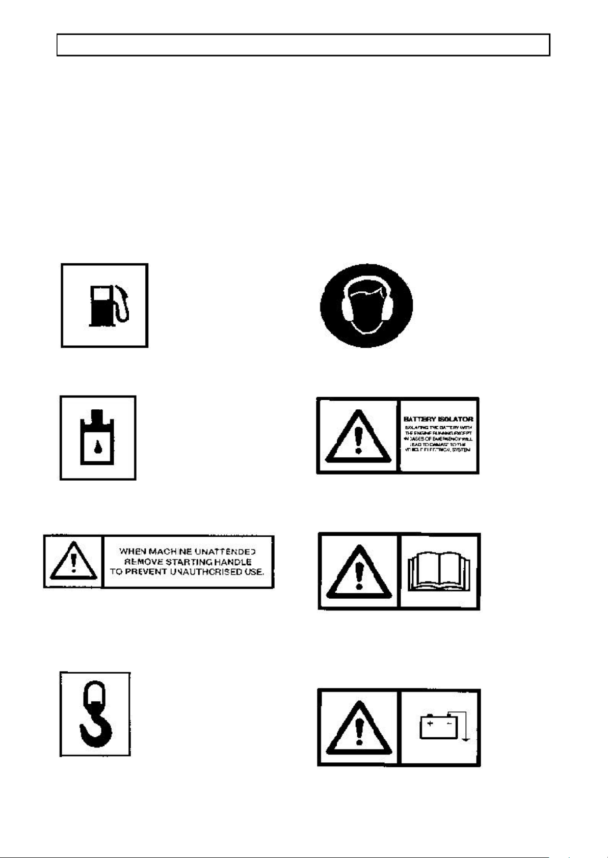
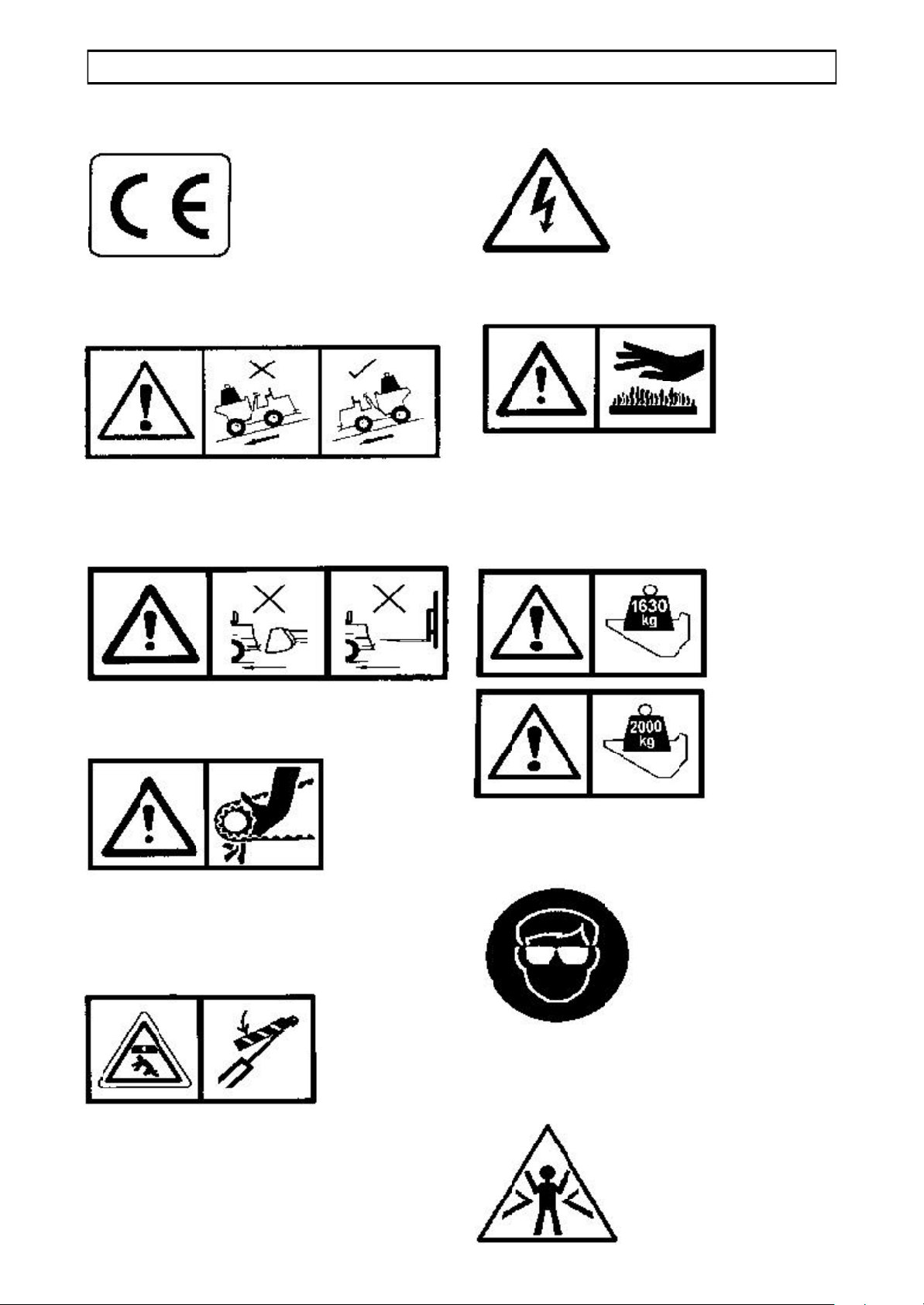
Attached to the dumper are several pictorial warning decals
Ensure that all decals fitted to the dumper are legible. If any should become detached,
they must be replaced immediately
For detailed information on how to safely use the items described by the decals, see the
“Safe working, Operation and Servicing” sections of this Handbook.
Descriptions of the decals are as follows:
Fuel tank filling point.
Hydraulic oil filling point.
Remove starting handle.
Wear ear protection.
The Battery Isolator is situated close to
this decal.
Read Operators Handbook, or
Operators Handbook storage place.
Attach lifting hooks to this eye.
connected to earth.
Page 12
SAFE WORKING 1.7
CE (EC machines only)
Always reverse down gradients when
loaded
Forks and buckets are not to be used to
push or lift the dumper.
Beware of electrical hazards
These surfaces may be hot.
The figures shown on these decals are
the maximum loads for the skips onto
which the decals are fastened.
Keep hands away from moving parts.
ISO Skip Support, when used, is pinned
around the tipping ram rod to prevent the
ram from closing.
Always wear eye protection.
Stand clear of the articulation area of the
dumper
Page 13

1.8 SAFE WORKING
Page 14
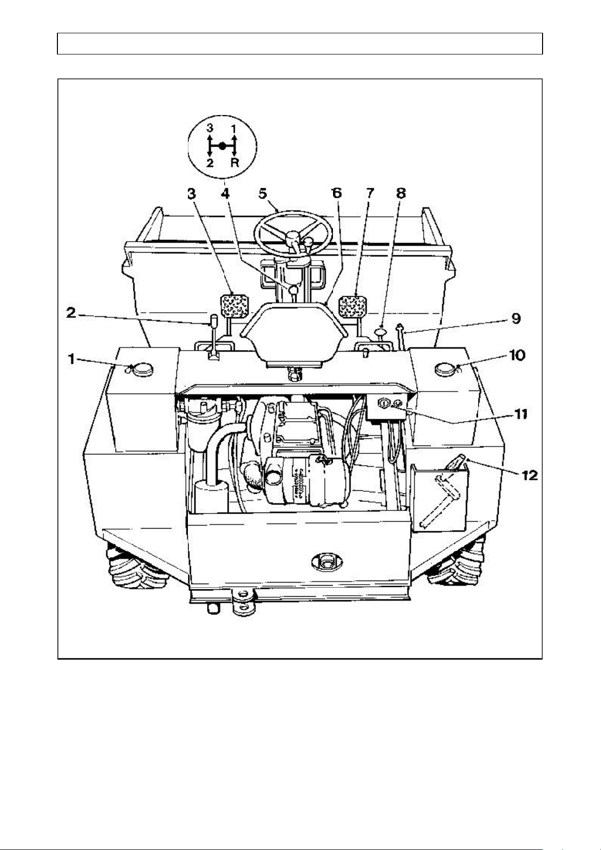
OPERATION 2.1
CONTROLS AND SERVICE POINTS
1 Hydraulic oil filler cap
2 Skip control, tip/return
3 Clutch
4 Gear lever
5 Steering wheel
6 Seat
7 Foot Brake
8 Accelerator
9 Parking brake
10 Fuel filler cap
11 Key start switch (where fitted)
12 Engine starting handle (stowage)
Page 15
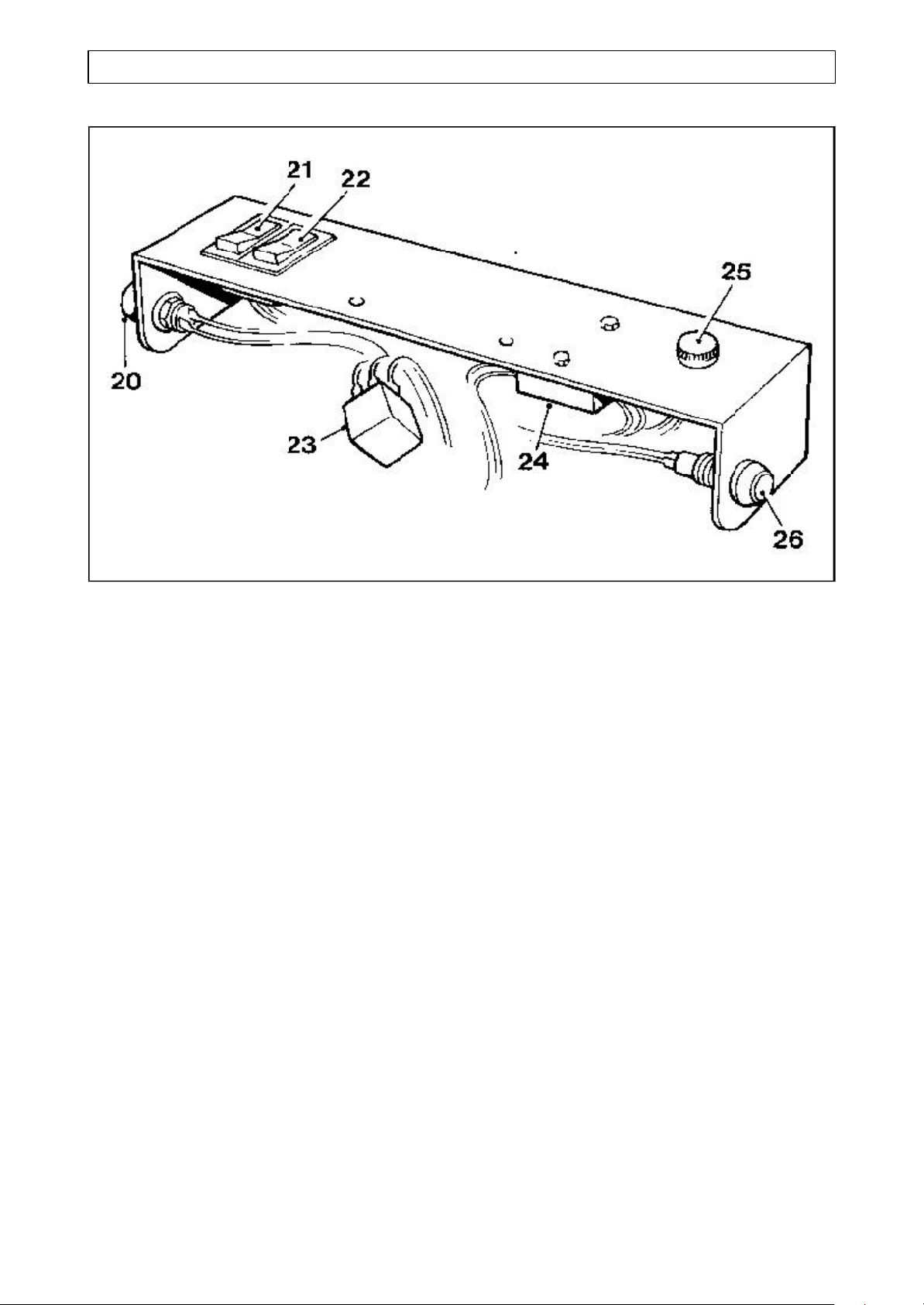
2.2 OPERATION
ROAD LIGHTS SWITCH PANEL
20 Horn
21 Switch: Side and head lights
22 Switch: Hazard warning lights
23 Flasher unit
24 Fuse box
25 Switch: Direction indicators
26 Warning light: Direction indicators
Page 16

OPERATION 2.3
DRIVING THE DUMPER
Safety warnings
Read also the “Safe Working” Section
before operating the dumper.
WARNINGALWAYS wear correctly fitting
protective clothing. Loose or
baggy clothing can be
extremely dangerous when
operating or servicing
machinery.
Only skilled personnel are
permitted to work with this
machine.
ALWAYS be aware of local
and national regulations
governing the use of this
machine.
Starting the engine
WARNINGNEVER use ether type
starting aids.
ALWAYS stop the engine if
the battery charge warning
light (where fitted) fails to
cancel.
Running-in a new engine
While a gradual ‘running-in’ of a new
engine is not necessary, it is
EXTREMELY IMPORTANT that the
following instructions should be followed
very closely during the first fifty hours of
operation.
1 Avoid overloading the engine.
2 Use the lower gears when operating
with heavy loads, and avoid continuous
operation at constant engine speeds.
3 Check the instruments frequently, and
keep the oil compartments and the
hydraulic reservoirs filled to their
recommended levels.
4 Do not operate the engine at high
speeds without a load.
5 Do not allow the engine to run at idle
speeds for long periods; this may cause
bore glazing and an increase in oil
consumption.
Operating in this way throughout the
machine’s life will prove beneficial to its
overall performance and efficiency.
Pre-start Checks
ALWAYS stop the engine if
warning lights illuminate.
Detect the fault before
continuing.
DO NOT PROCEED IF A
FAULT IS EVIDENT
NEVER attempt to start the
dumper by pushing or towing.
NEVER operate controls
unless you are seated on the
machine, and ALWAYS
remain in the driving seat
whenever the engine is
running.
WARNING NEVER commence work with
the machine until the checks
detailed in “Every 10
operating hours, or daily”
have been carried out. (See
Service Schedule).
Check that all controls are clean and not
slippery, and that they all function
correctly.
Check that the areas around pivot points,
rams and linkages are all free from mud,
ice and debris.
Check that all grab handles, steps and
platforms are clean and dry.
Check the machine for any obvious
damage or faults.
Check that all decals can be clearly read.
Page 17
2.4 OPERATION
DRIVING THE DUMPER
Petter PH2 engines (UP TO 1988)
To start Petter PH2 engines:
Ensure the parking brake is in the raised
“ON” position.
Ensure gear lever is in the neutral
position.
WARNINGIf a starting handle is to be
used, see that the shaft is
greased. Make sure the
starting handle can be freely
withdrawn.
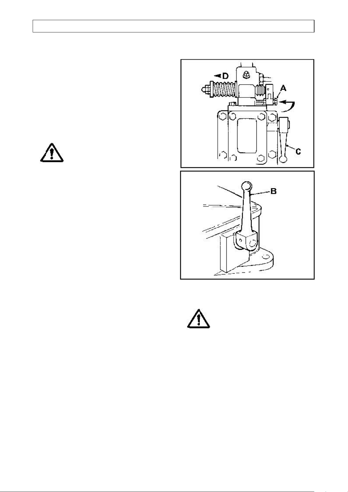
On the engine, lift the overload stop (A)
and move the fuel pump rack (D) in the
direction of the arrow to the fully open
position.
Operate the fuel pump priming lever (C)
approximately six times. (This is
unnecessary with a warm engine.)
Lift the decompression lever (B) to the
vertical position. Crank the engine as fast
as possible or use the starter motor.
When the engine is turning at a good
speed, knock down the lever (B). The
engine should now fire.
If the engine does not fire, lift the
decompressor lever (B) and slowly turn
the engine a few times before attempting
to start again. Do not operate the starter
motor for more than 20 seconds at a time.
.
Note:If it is necessary to bleed and prime
the fuel system, consult the PH2
Engine Operators Handbook.
To stop PH2 engines:
WARNING NEVER stop the engine by
using the decompressor lever.
This will lead to damaged
valve seats and cylinder head
joints.
DO NOT stop the engine by
allowing the tank to run dry.
This will make it necessary to
bleed and prime the system.
DO NOT remove or alter the
setting of the overload stop.
It is advisable to run on light load for a
few minutes before stopping.
Raise the priming lever (C) to the vertical
position, or move and hold the fuel pump
rack (D) away from the fly wheel until the
engine stops.
Page 18
OPERATION 2.5
DRIVING THE DUMPER
Lister ST2 engines (UP TO 1988)
To hand start Lister ST2 engines:
Ensure the parking brake is in the raised
“ON” position.
Ensure gear lever is in the neutral
position.
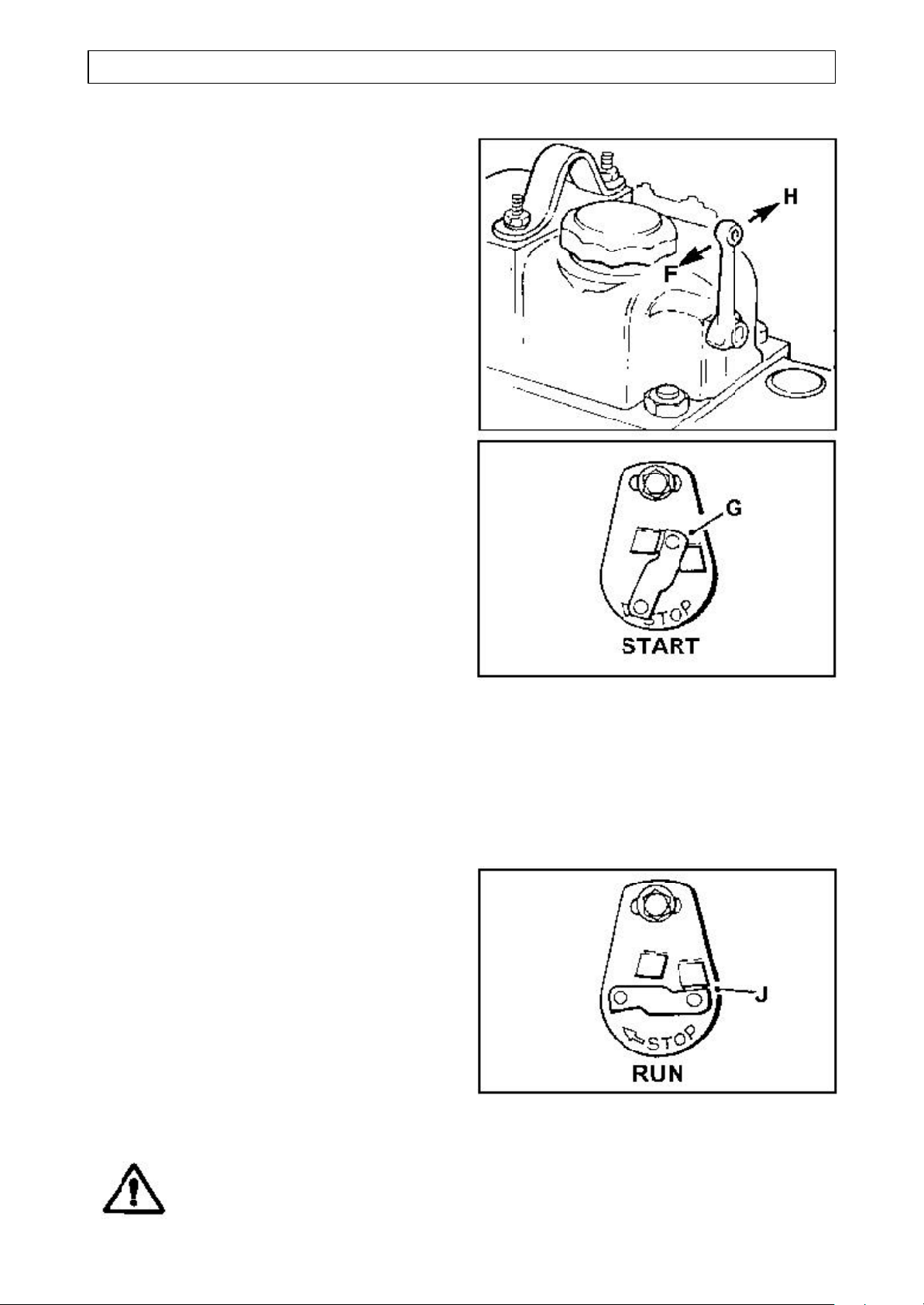
Move the decompressor lever over
towards the flywheel (F).
Pull the control lever outwards and allow it
to rotate anticlockwise so that it abuts
against the top stop and is in a vertical
position (G).
IMPORTANT: Ensure that the starting
handle is of the correct type and is fully
servicable. Lightly oil the end of the
starting shaft and the starting handle.
Check the arrow on the handle for correct
rotation, then turn the handle in the
opposite direction to that required to start
engine. This is done in order to check that
the clutch pin will disengage from the
keyway, and does not bind on the starting
shaft.
ENSURE THERE ARE NO BURRS ON
THE SHAFT.
IMPORTANT: With the starting handle, turn the engine slowly from 3 to 20 turns according to the temperature and period of standing unused, in order to prime the combustion chamber and the lubricating oil system.
Turning the starting handle in the correct
rotation, crank the engine really fast and
when maximum cranking speed is
reached move the decompressor lever
away from the flywheel (H). Retain a firm
grip on the starting handle and continue to
crank until the engine fires. Remove the
starting handle from the shaft.
WARNING It is dangerous to allow the
handle to rotate on the
running shaft.
IMPORTANT: As soon as the engine
reaches normal speed, turn the control
lever clockwise to the horizontal position
so that it abuts the horizontal stop (J).
Page 19
2.6 OPERATION
DRIVING THE DUMPER
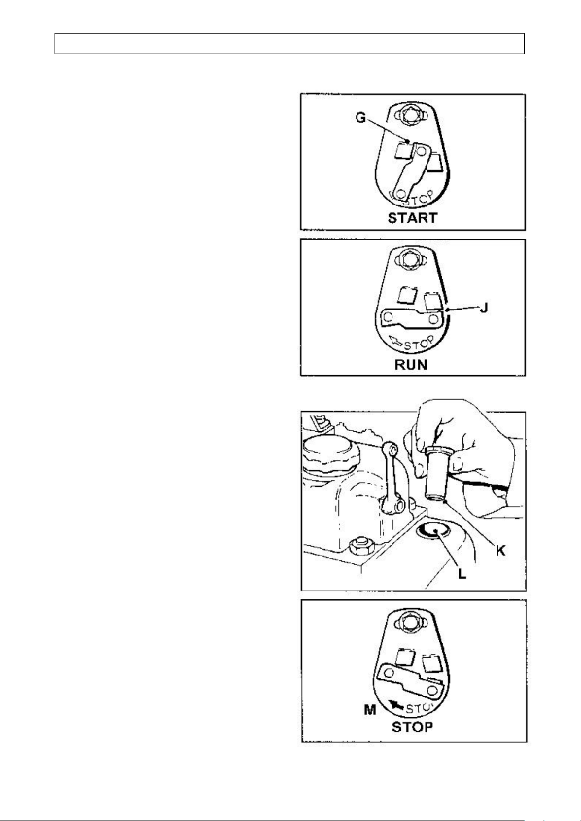
To key (Electric) start Lister ST2
engines:
Ensure the parking brake is in the raised
“ON” position.
Ensure gear lever is in the neutral
position.
Depress and hold down the accelerator.
Pull the control lever outwards and allow it
to rotate anticlockwise so that it abuts
against the top stop and is in a vertical
position (G).
Turn the starter key and release
immediately the engine fires. Do not
motor the engine continuously for more
than 20 seconds.
Release the accelerator pedal.
IMPORTANT: As soon as the engine
reaches normal speed, turn the control
lever clockwise to the horizontal position
so that it abuts the horizontal stop (J).
Cold Starting Below -10oC (14oF)
A cup and plunger is fitted to the
combustion air intake port on ST engines.
Operate as follows:
Withdraw the plunger (K) and fill one
third of the cup (L) with the same type
of lubricating oil as used in the engine.
Replace the plunger and inject the oil
just before starting the engine.
The device must not be used more than
three times in succession. When hand
starting, turn the engine 20 revolutions
with the fuel on after injecting the oil,
before attempting to start.
To stop engine
Turn the control lever clockwise in the
direction of the arrow (M) and hold it until
the engine stops.
Page 20
OPERATION 2.7
DRIVING THE DUMPER
TS/TR2 engines
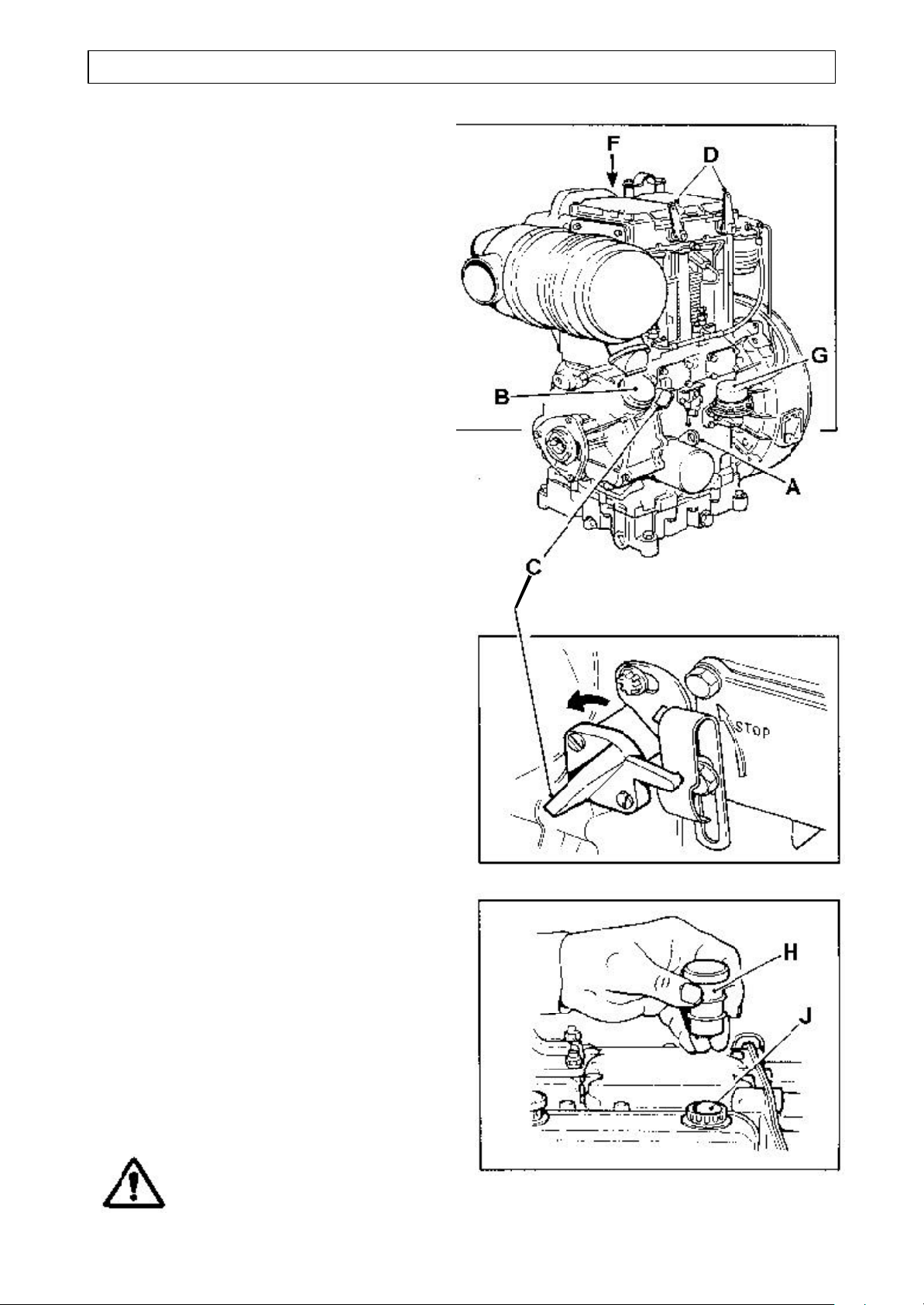
Description
A Dipstick
B Lubricating oil filler
C Engine control
D Decompressor levers
F Cold start oil cup
G Fuel lift pump
Automatic Exess Fuel Device
The engine is fitted with an automatic
excess fuel device which becomes
operative, ready for the next start, when
the engine is stopped.
If the engine stops other than by the
operation of the engine control, the control
(C) must be turned anti-clockwise to the
‘STOP’ position and released before the
device can operate.
As the engine runs up to speed the
excess fuel device will automatically reset
to the normal running position.
Cold Starting Below -10oC (14oF)
A cup and plunger is normally fitted to the
combustion air intake port on TR and TS
engines.
With the fuel turned on, turn the engine
for up to 20 revolutions to prime the fuel
and lubrication systems.
Withdraw the plunger (H) and fill one
third of the cup (J) with the same type
of lubricating oil as used in the engine.
Replace the plunger and inject the oil
just before starting the engine.
WARNING The device must not be used
more than three times in
succession during the same
attempt to start the engine.
Page 21
2.8 OPERATION
DRIVING THE DUMPER
Hand starting TS/TR2 engines
Ensure the parking brake is in the raised
“ON” position.
Ensure gear lever is in the neutral
position.
Always use the correct starting handle
which has been designed for the
engine.
Ensure there are no burrs on the handle.
Before attempting to use the handle,
clean and lightly oil that part of it which
fits onto the engine.
WARNINGDo not attempt to use a
handle if it is damaged in any
way.
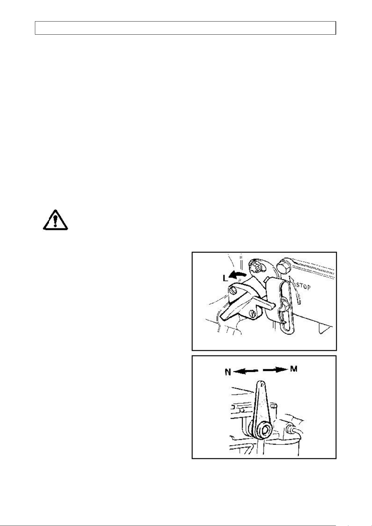
Turn the engine control lever
anti-clockwise to the “STOP” position (L)
and release it.
Move the decompressor lever towards the
flywheel (M).
Insert the correct handle into the starting
housing.
Turn the engine slowly for up to 20 turns
to prime the combustion chamber and
lubricating oil system.
Maintaining a firm grip on the starting
handle, crank the engine really fast and
when sufficient speed is obtained move
the decompressor lever away from the fly
wheel (N) and continue to crank until the
engine fires.
Retain a firm grip on the handle and
remove it from the engine.
Page 22
OPERATION 2.9
DRIVING THE DUMPER
Key Starting TS/TR2 engines
Ensure the parking brake is in the raised
“ON” position.
Ensure the gear lever is in the neutral
position.
Fully depress and hold down both clutch
and accelerator pedals.
Check that the decompressor lever, (if
fitted) is away (N) from the flywheel.
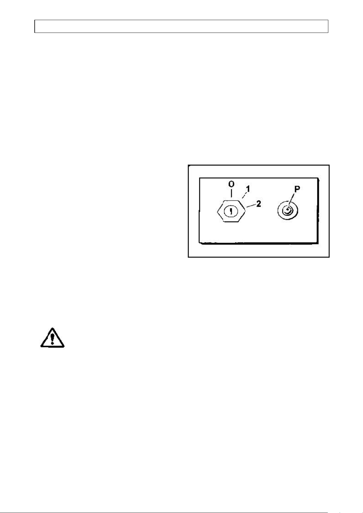
Turn the engine control lever
anti-clockwise to the “STOP” position (L)
and release it.
Turn the start key clockwise to position
(1), the battery charging light (P) will
illuminate.
Turn the key and hold at the “START”
position (2) until the engine fires and then
release it immediately.
If the engine fails to start within 20
seconds, release the key and attempt to
restart after allowing sufficient time for all
moving parts to stop.
Stopping the engine
WARNING Never stop the engine by
operating the decompressor
lever or valve damage may
occur
Key start engines: Turning
the starter key to the “OFF”
(0) position will not stop the
engine.
It is advisable to run on light load for a
few minutes before stopping.
Turn the engine control anti-clockwise to
the “STOP” position (L) and hold it there
until the engine comes to rest.
Key start engines: After the engine has
stopped, turn the starter key to the “OFF”
(0) position.
Page 23

2.10 OPERATION
DRIVING THE DUMPER
Gradients
IMPORTANT: Read the notes in “Safe
Working” and also remember the
following:
Slippery or loose surface conditions can
adversely affect safe machine
operation, particularly on gradients.
ALWAYS choose routes that avoid
steep, slippery or loose gradients.
NEVER park the machine on a
gradient.
NEVER attempt to turn on, or drive
across, a gradient.
ALWAYS drive forwards up gradients
when loaded.
ALWAYS reverse down gradients when
loaded.
NEVER tow up or down gradients.
NEVER operate on a gradient which
exceeds 25% (1 in 4), or across
gradients which exceed 16% (1 in
6). This should be reduced where
surfaces are wet or unstable.
NEVER operate high discharge or
rotating skip options on gradients.
Stopping the dumper
IMPORTANT: Never make unnecessary
‘crash’ stops when travelling at speed,
especially in forward direction.
Release accelerator and brake to a halt
progressively.
Select neutral gear.
Apply parking brake when stationary.
Stop the engine. Turn the starter key to
the ‘OFF’ position, and remove the key.
Leaving the dumper
Ensure the machine is parked on firm,
level ground. Do not park on a gradient.
Check that the parking brake is applied.
Ensure that the skip is fully lowered.
With the engine stopped, operate the skip
hydraulic control lever fully in each
direction several times to ‘dump’ hydraulic
pressure from the system.
Remove starter key (where fitted) from
switch.
Electric start dumpers: If unattended for
Braking
Dumpers with hydraulically operated
brakes
The brake pedal operates a hydraulic
master cylinder that supplies oil to brakes
within the front axle. (Brakes fitted within
the rear axle are an option.)
The handbrake operates a caliper that
acts upon a disc mounted on the
transmission.
some time, remove earth cable from
battery, or activate the Battery Isolator,
(where fitted).
Engaging gear lever
When changing gear, always depress the
clutch pedal before moving the gear lever
from one gear to another.
Page 24
OPERATION 2.11
DRIVING THE DUMPER
Skip operation
Loading
Never remain on the dumper when using
excavators or loaders to load the skip.
Stop the engine, apply the parking brake,
dismount, and stand well clear.
Ensure that the load is evenly distributed
in the skip. Never carry loads in such a
manner as to affect the forward vision.
Never exceed the rated payload. The
weights of all loads above skip water level
must be checked.
Tipping
Only discharge on level ground.
It is recommended that only free flowing
materials be tipped. Take extra care when
tipping non free running loads.
Skip control lever
The control lever has three positions; they
are, Tip (or Dump), Hold and Return.
To tip the skip:
Move the lever to DUMP.
To return the skip:
Move the lever to RETURN.
If the lever is released when in the DUMP
or RETURN position, it will automatically
return to the central HOLD position and
movement of the skip will stop. In this
way, the speed at which the skip is tipped
can be finely controlled.
However, if the skip is raised and the
engine is switched off, DO NOT operate
the control lever as the skip will rapidly
lower to the chassis
Rotating skip (manual rotation)
Rotating skip (hydraulic rotation)
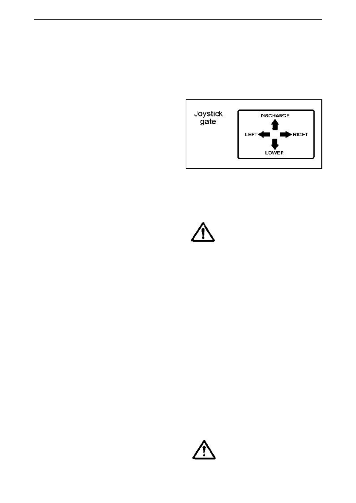
The skip is operated by a joystick control
valve; the lever of which is moved through
a gate.
Because of the gate it is not possible to
move the lever diagonally, therefore it is
not possible to tip and slew the skip
simultaneously.
WARNING Before attempting to slew the
skip; the dumper must be
stationary, on level ground,
with the front and rear chassis
in-line (not articulated) and
with the parking brake applied
When the skip is fully lowered, the rear of
the skip locates into a recess in the
chassis. This is to ensure that there is no
rotary movement of the skip while the
dumper is travelling.
To slew the skip:
Look at the rear of the skip where it is
recessed into the chassis.
With the joystick lever, gently tip the
skip forward just sufficiently to raise the
rear of the skip clear of the recess.
Allow the lever to “self-centre”.
Move the lever in the direction that you
wish to turn the skip.
Allow the lever to “self-centre”.
Move the lever forwards to tip the skip.
Reverse the procedure to return the
skip to the travelling position.
After releasing the turntable locking catch,
rotate the skip manually, then tip by using
the hydraulic control lever.
When returned to the carrying position,
ensure that the turntable catch is locked.
WARNING Be sure that the rear of the
skip has fully seated in its
recess in the chassis before
travelling.
Page 25

2.12 OPERATION
DRIVING THE DUMPER
Towing with the dumper
Dumpers are not designed as towing
vehicles, however, trailers may be towed
providing that:
1 The combined weight of the trailer and
its load does not exceed the specified
maximum dumper payload.
(see"specifications")
2 Trailers may be towed in first gear on
level dry ground, provided a purpose
made towing pin is used.
3 The dumper skip must be loaded with
half the rated payload to ensure tyre
adhesion when braking.
Never tow loads up, down or across
gradients.
Towing the dumper
The dumper should only be towed if
recovery is needed of a broken-down unit,
or to free a “bogged down” machine.
Always ensure that ropes, chains, etc.
used to tow the dumper have sufficient
safe working load capability.
When towing the dumper, always ensure
that the speed is kept to an absolute
minimum.
Always tow the dumper with the gear
lever in neutral.
Never attempt to start the dumper by
pushing or towing.
Page 26
SERVICE 3.1
SAFE WORKING
WARNINGRead the safety notes in
“Safe Working”, Section 1
of this book.
Also note the following :
Safe handling of oils, filters and
filter elements
WARNINGDo not allow oils to come into
regular contact with skin. This
can lead to serious skin
diseases. Medical evidence
suggests they may include
skin cancer.
Always wear protective gloves
when handling oils for
topping up, draining, or
refilling.
Dispose of waste oil into
waste oil storage tanks. if
storage tanks are not
available, consult your
Distributor or local authority
for addresses of local
designated disposal points.
It is illegal to dispose of waste
oil into drains or water
courses or to bury it.
The materials used in the
manufacture and treatment of
some filters and elements
may cause irritation or
discomfort if they come into
contact with the eyes or
mouth and they may give off
toxic gases if they are burnt.
After handling any filters or
oils the users hands should
be thoroughly washed,
particularly before eating.
Used filter elements contain
some of the filtered oil and
should be handled and
disposed of with care.
Page 27
3.2 SERVICE
SERVICE SCHEDULE
IMPORTANT: The engine will require additional services or adjustments in addition to
those listed below (See the appropriate Engine Operator’s handbook or Workshop
Manual).
WARNING Warning lights and indicators
REQUIRE IMMEDIATE ACTION.
SERVICE OPERATION REFERENCE PAGE
Every 10 operating hours, or daily, the above and the following
Engine oil level Engine 3.4
Fuel tank level Engine 3.6
Air cleaner Engine 3.9
Wheel nut tightness Wheels & tyres 3.22
Axle oil seals Axles 3.23
Hydraulic oil level & hose condition Hydraulic system 3.16
Every 50 operating hours, or weekly, the above and the following
Axle nuts Axles 3.23
Axle oil levels Axles 3.23
Tyre pressures & condition Wheels & tyres 3.22
Fuel tank filler strainer Engine 3.6
Battery electrolyte level Battery 3.13
Grease nipples Greasing 3.19
Gearbox / Transfer box oil levels Gearbox / Transfer box 3.10
Parking brake
Check function of the parking brake and adjust if necessary.
Propeller shaft
Tighten securing nuts. (See also Propeller Shaft Installation on page 3.12)
Brake pedal travel
Check the action of the brake pedal; it should have a short travel and firm
action. If travel is excessive, or the action spongy, have the brakes serviced
by your distributor.
First 100 operating hours
Hydraulic oil filter Hydraulic system 3.17
Page 28

SERVICE 3.3
SERVICE SCHEDULE
SERVICE OPERATION REFERENCE PAGE
Every 125 operating hours, the above and the following
Air cleaner element Engine 3.9
Every 250 operating hours, the above and the following
Engine oil and filter Engine 3.5
Fuel filter Engine 3.7
Every 300 operating hours, the above and the following
Hydraulic oil filter Hydraulic system 3.17
Every 500 operating hours, the above and the following
Air cleaner element Engine 3.9
Fuel filter Engine 3.7
Frame assembly bolts Check all structural nuts & bolts for tightness.
Every 1000 operating hours, the above and the following
Hydraulic oil & filter Hydraulic system 3.17
Gearbox / Transfer box oil change Gearbox / Transfer box 3.10
Axle oil change Axles 3.23
Every 2000 operating hours, or 2 years, the above and the following
Brake system overhaul Braking system 3.20
Extra services
Dirty working conditions
Increase the frequency of all services during extremes of dirt, heat and cold,
especially those relating to clean air, cooling efficiency, lubrication and machine
cleanliness.
Laying-up protection
When a machine is to remain idle, remove the battery to the workshop. Seal all
openings: air intake, exhaust breathers. Grease bright parts and protect rubber
components from direct sunlight. Fill the fuel tank, check the tyre pressures
and exhaust any pressure from the hydraulic system.
Page 29
3.4 SERVICE
ENGINE
Engines fitted in dumpers
Up to 1985: Lister ST2 and Petter PH2
1985 to 1989: Lister-Petter PH2
1985 to 1989: Lister-Petter TS2
Note: from 1989 the TS2 has been offered as an
option
1989 to date: Lister-Petter TR2
Engine lubrication oil
For engine oil grades and oil change
periods when operating in temperatures
above 30
o
C, see “Engine Handbook”.
IMPORTANT
To service the following engines,
Lister ST2
Petter PH2
Please refer to relevent Engine Operator’s
Handbook or Workshop Manual.
Lister-Petter TS/TR2
These engines will require additional
services and adjustments in addition to
those quoted in this handbook. Please
refer also to the relevant Engine
Operator’s Handbook or Workshop
Manual.
Every 10 operating hours, or
daily
Engine oil level
WARNING Lubrication oil cleanliness is
vital for the successful
operation of your engine. The
oil should be stored under the
cleanest possible conditions.
When changing or topping-up
oil, use only clean
receptacles.
Always wear protective gloves
when handling oils for
topping up, draining, or
refilling.
Oils and fuels can cause skin
irritation. Wear suitable
protective clothing to prevent
skin contact.
After handling oils the users
hands should be thoroughly
washed, particularly before
eating.
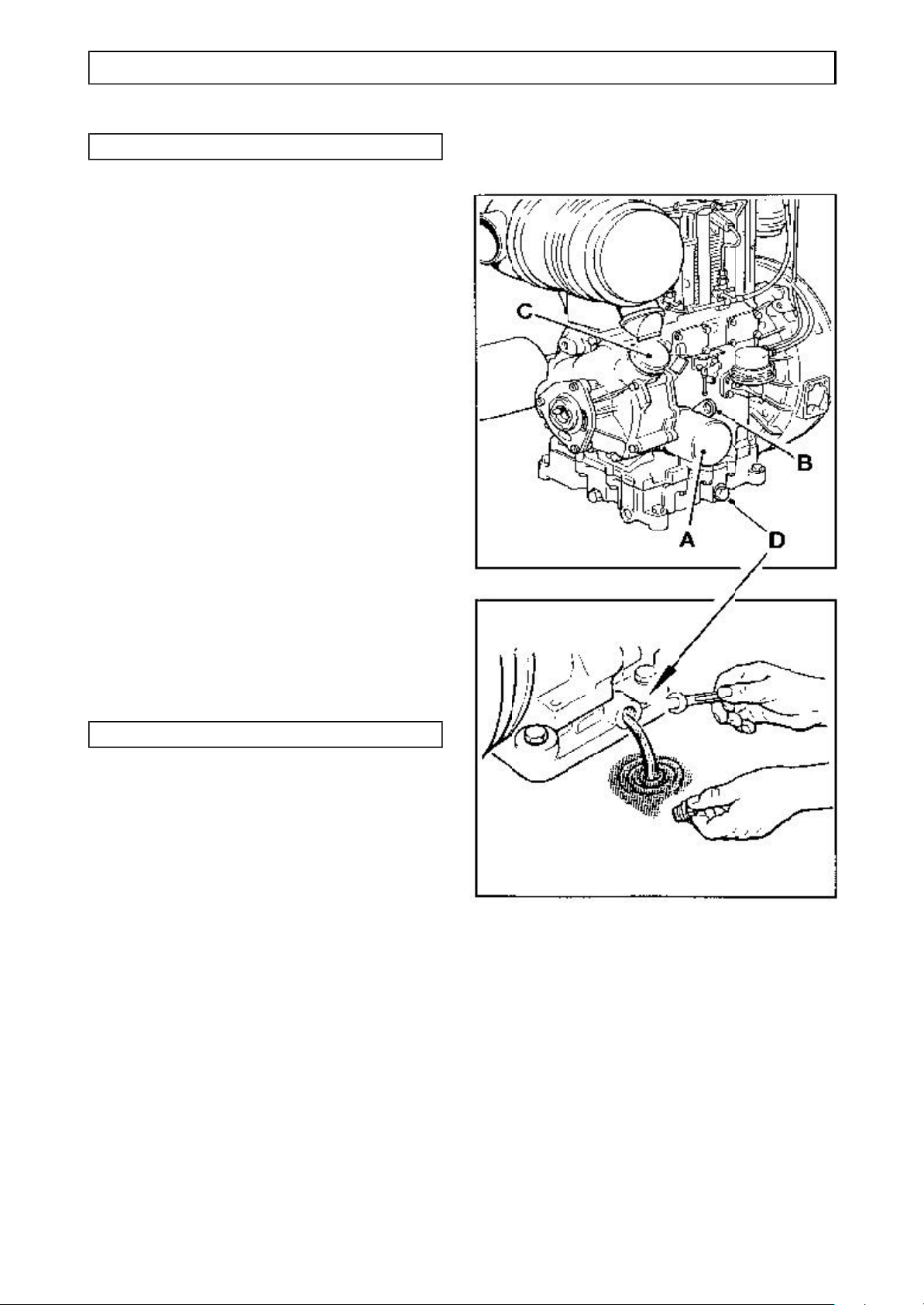
Check lubrication oil level as follows:
Stop the engine and allow the oil to
settle.
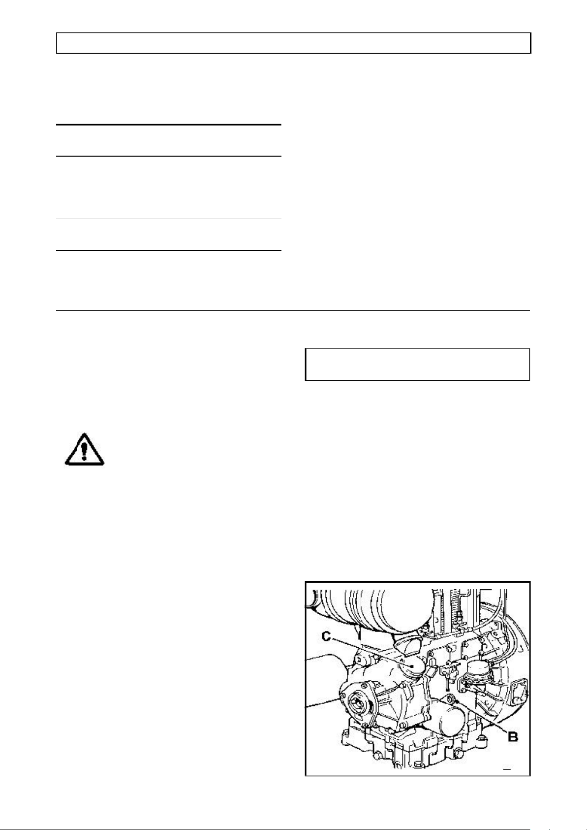
Remove and clean the dipstick (B),
then check that the oil is at the full
mark. If the level is low, top up through
the filler (C) to the full mark with clean
oil of the correct grade. DO NOT
OVERFILL.
For correct grade of engine oil, see
“Specifications”.
Page 30
SERVICE 3.5
ENGINE
Every 250 hours
Engine oil
Drain and refill the oil sump as follows:
If possible run the engine immediately
before draining the oil.
Place a suitable container under the
drain plug. Remove the drain plug (D)
and drain oil.
Clean and coat the threads of the drain
plug with an appropriate sealant.
Replace the drain plug (D) taking care
not to overtighten it.
Fill the sump through the oil filler (C) to
the top mark on the dipstick (B).
Start the engine, run it for a few
minutes and check the drain plug does
not leak.
Stop the engine, allow the oil to settle
and check the level on the dipstick.
Add more oil if necessary.
Every 250 hours
Oil filter
Change oil filter element as follows:
Using a suitable strap wrench, unscrew
and remove the old filter (A).
Do not attempt to clean the old filter!
Dispose of it safely.
Thoroughly clean the crankcase filter
housing face.
Stop the engine, allow the oil to settle
and check the level on the dipstick (B).
Apply a small amount of clean engine
oil to the filter sealing joint.
Do not use a strap wrench to fit the
new element.
Screw on the new filter by hand, until
the sealing joint is just touching the
crankcase and then tighten a further
half turn.
Run the engine and check for any oil
leaks.
Add more oil if necessary.
Do not check oil level until the engine
has been stopped for 2 minutes.
Remove and clean dipstick then check
that the oil is at the full mark. If level is
low, top up through the filler to the full
mark with clean oil of the correct grade.
DO NOT OVERFILL.
For correct grade of engine oil, see
“Specifications”.
Page 31

3.6 SERVICE
ENGINE
Every 10 operating hours, or
daily
Fuel tank
Fill the fuel tank at the end of each day to
reduce overnight condensation within the
tank.
WARNINGNever mix gasoline or any
other fuel mixes with diesel
fuel because of increased fire
or explosion risks.
Never remove the filler cap, or
refuel, with the engine
running.
Never smoke when refilling
the tank.
To fill the tank:
Stop the engine.
Clean the area around the filler cap.
Remove the cap.
Fill the tank. Do not fill the tank to
capacity. Allow room for expansion,
and wipe up spilt fuel immediately,
otherwise paintwork will be damaged.
Replace cap.
Fuel filter
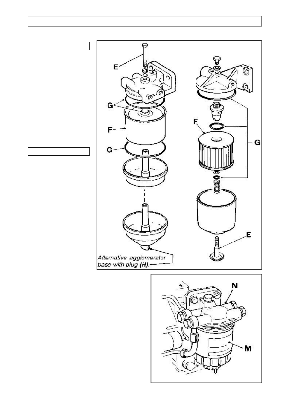
(Cartridge Agglomerator)
Check that there is no accumulation of
water in the base of the agglomerator by
unscrewing the drain tap (L) sufficiently to
allow any water to empty, then retighten
the tap.
Every 50 hours
Fuel tank strainer
When filling the fuel tank, check that the
strainer within the filler neck is clear of
sediment.
Page 32
SERVICE 3.7
ENGINE
Every 250 hours
Fuel filter
element/cartridge
Change the fuel filter
element/cartridge if the
fuel being used is not
perfectly clean (see
below).
Every 500 hours
Filter Element, or
Cartridge
Agglomerator
Change Fuel Filter
Element as follows :
Remove the retaining
bolt (E).
Remove the element
(F) and joints (G) .
Fit new element and
new joints.
Replace and tighten
retaining bolt (E).
Prime the system.
Change Cartridge Agglomerator as
follows:
The cartridge agglomerator should be
renewed more frequently than every 500
hours, if for any reason the fuel is known
to be dirty.
To change the cartridge agglomerator:
Use a suitable strap wrench to unscrew
the cartridge (M) from the head (N).
DO NOT USE A STRAP WRENCH TO
FIT THE NEW CARTRIDGE! Screw a
new cartridge onto the head and hand
tighten only.
Page 33
3.8 SERVICE
ENGINE
Priming the fuel system
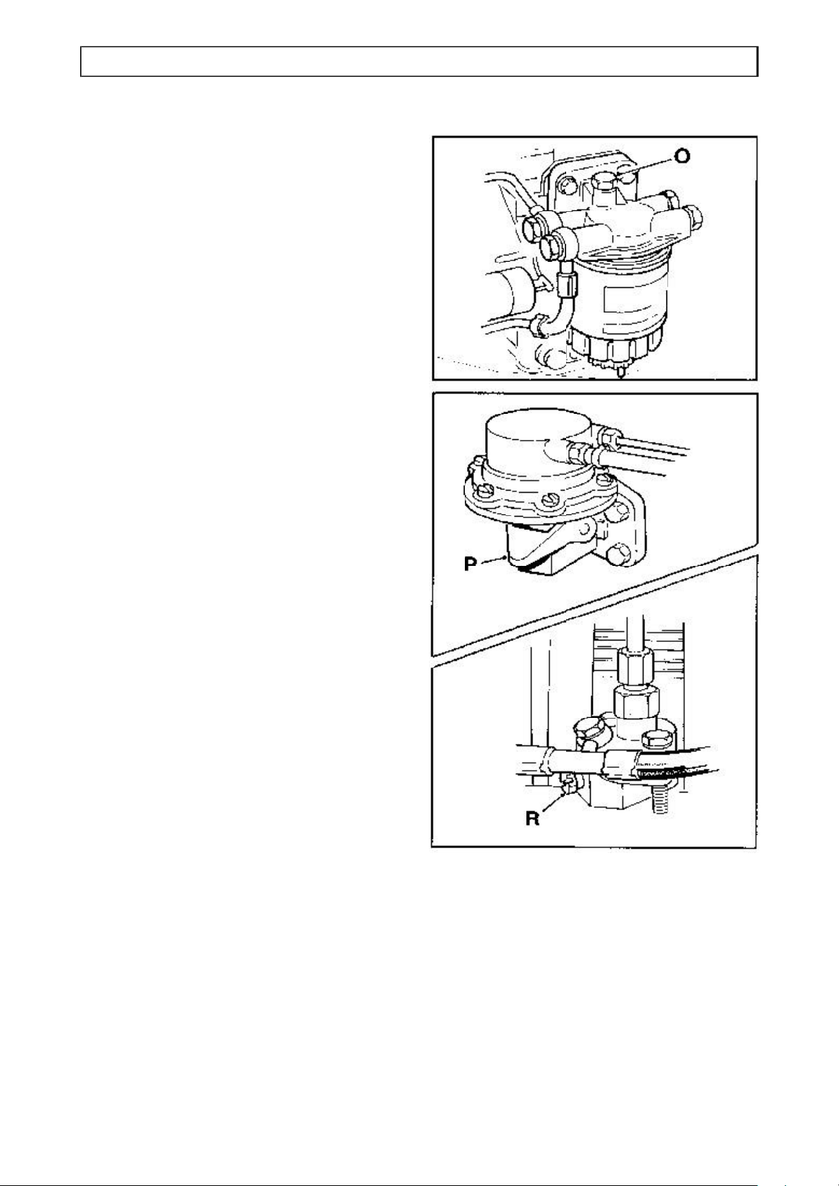
Prime the system as follows:
Fill the fuel tank
Move the engine control lever to the
RUN position.
Release the bleed screw (O) on the
filter head, then operate the priming
lever (P) on the lift pump until a full air
free flow is obtained
Retighten bleed screw (O)
Vent each injector pump in turn by
releasing screw (R), then operate the
priming lever (P) on the lift pump until a
full air free flow is obtained
Retighten bleed screw (R), then repeat
for the other injector pump.
Page 34
SERVICE 3.9
ENGINE
Every 10 operating hours, or
daily
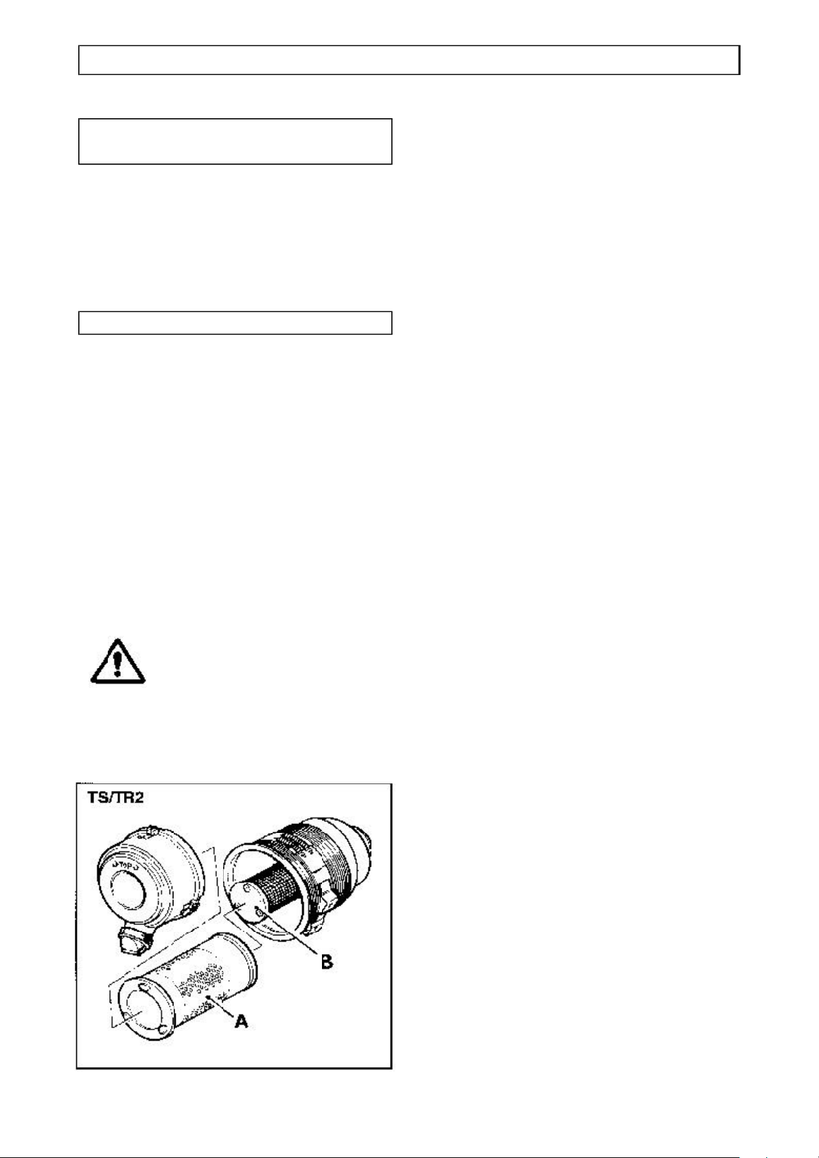
Air cleaner: clean/replace
Clean or replace the outer element (A)
under very dusty conditions as described
below:
Every 125 operating hours
Air cleaner: clean/replace
Clean or replace the outer element (A)
under moderately dusty conditions as
described below:
Access the elements by unhooking the
retaining clips and removing the cover.
Remove the outer element (A) and
clean or replace it as necessary.
Replace the element.
Replace the cover with the inlet facing
downwards.
WARNING No attempt must be made to
clean the inner element (B).
After the outer element (A)
has been cleaned three times
the inner element (B) must be
replaced.
Page 35
3.10 SERVICE
GEARBOX
Safe handling of oils
WARNING Do not allow oils to come into
regular contact with skin. This
can lead to serious skin
diseases. Medical evidence
suggests they may include
skin cancer.
Always wear protective gloves
when handling oils for
topping up, draining, or
refilling.
Dispose of waste oil into
waste oil storage tanks. if
storage tanks are not
available, consult your
Distributor or local authority
for addresses of local
designated disposal points.
It is illegal to dispose of waste
oil into drains or water
courses or to bury it.
Every 1000 operating hours
Change gearbox oil
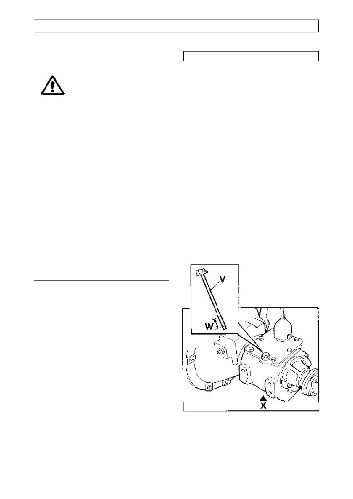
Clean the areas surrounding the dipstick
(V) and drain plugs (X).
Place a suitable container beneath the
drain plug.
CAUTION: Before removing the drain
plug be sure to stand to one side to avoid
the oil that will spill from the hole.
Remove the drain plug (X) and drain the
gearbox. (Do not lose its sealing washer)
Replace drain plug with its sealing
washer.
Remove the dipstick (V) from the filler
hole.
Fill with oil. Check that the final level is
between the two marks on the dipstick. It
is most important not to overfill.
For the correct type and grade of oil, see
“Specifications”.
Every 50 operating hours, or
weekly
Check gearbox oil level
Check the gearbox oil level when the
machine has stood for 2 minutes.
Clean the area around the dipstick/filler
(V) before removing.
Remove the dipstick and check the oil
level. Top-up between the two marks
(W). It is most important not to overfill.
For the correct type and grade of oil, see
“Specifications”.
Page 36
SERVICE 3.11
TRANSFER BOX
Every 50 operating hours, or
weekly
Check transfer gearbox oil level
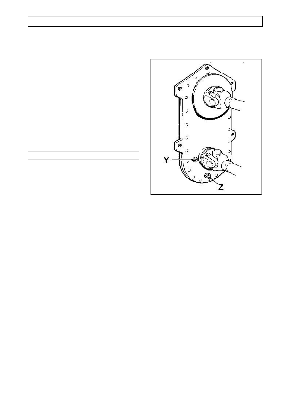
Clean the area surrounding the filler/level
plug (Y) before removing it.
Check and top-up through the filler/level
plug hole (Y) until the oil is level with the
bottom of that hole.
For the correct type and grade of oil, see
“Specifications”.
Every 1000 operating hours
Change transfer gearbox oil
Place a suitable container beneath the
drain plug (Z).
Drain oil by removing the plug (Z) .(Do not
lose its sealing washer)
Replace drain plug with its sealing
washer.
Fill with oil at filler/level plug (Y) to the
correct level. Replace filler/level plug with
its sealing washer.
For the correct type and grade of oil, see
“Specifications”.
Page 37
3.12 SERVICE
PROPELLER SHAFT
Propeller shaft Installation
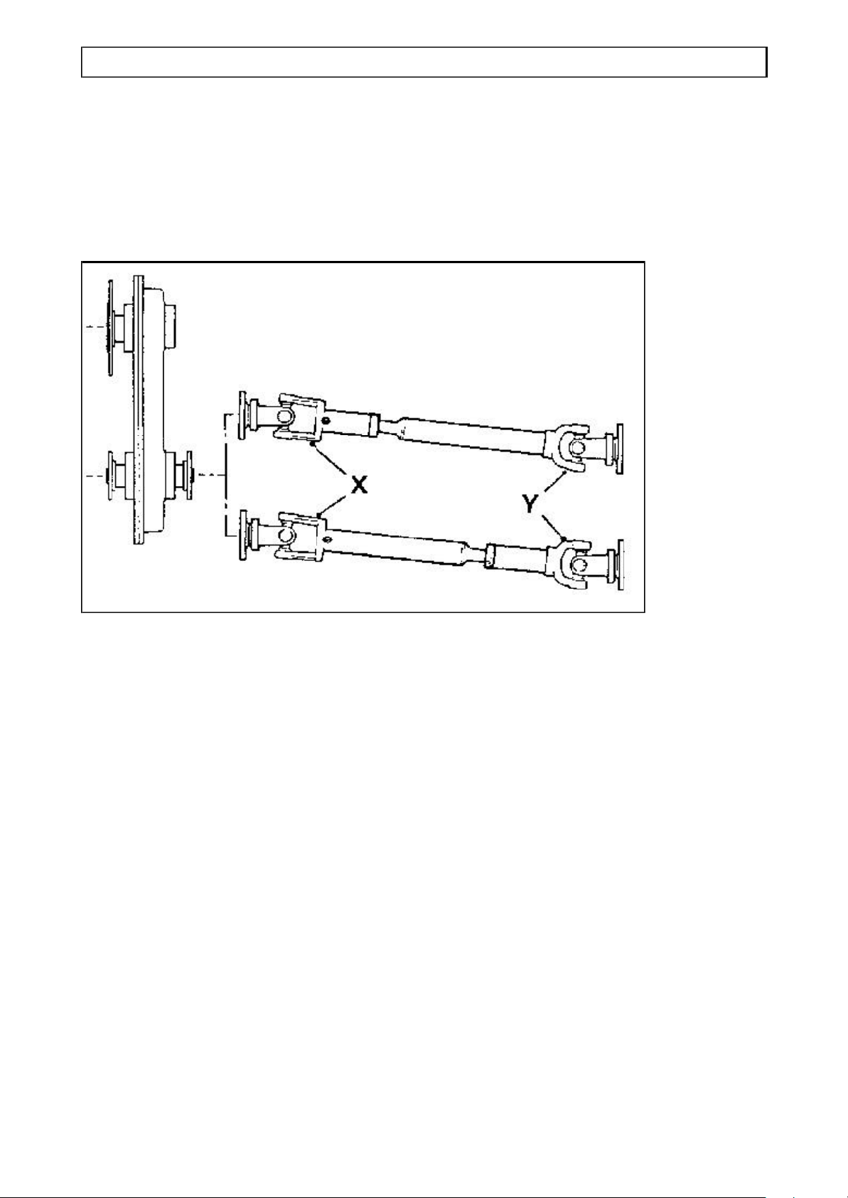
ALWAYS ensure that the larger yoke (X)
of the propeller shaft is fitted to the
transfer box, NOT the smaller yoke (Y).
Page 38
SERVICE 3.13
BATTERY
Safe handling of batteries
WARNINGThe battery contains a
sulphuric acid electrolyte
which can cause severe burns
and produce explosive gases.
Wear protective clothing,
gloves and goggles when
servicing the battery.
Avoid contact with the skin,
eyes or clothing. If spilled
onto the skin, flush
immediately with cold water.
If splashed into the eyes, flush
immediately with cold water
for 15 minutes and get prompt
medical attention.
Do not take internally. If
accidentally swallowed, call a
doctor immediately.
Do not use a naked flame or
smoke near the battery. Do
not produce sparks with cable
clamps when charging the
battery or starting the engine
with a slave battery.
Every 50 hours
Check battery electrolyte level
The battery is situated beneath a cover
on the left-hand side of the dumper.
Ensure that the electrical connections are
clean and tight, and coat the terminals
with petroleum jelly to protect them from
corrosion.
Remove battery filler plugs and check that
the electrolyte level is between 6 - 9 mm
(0.25 - 0.37 in) above the tops of the
separators.
If necessary, top-up with distilled water.
Replace battery filler plugs and tighten
securely.
Battery removal
WARNING If the battery is to be removed
from the machine, ensure the
following procedure is used.
Switch the engine off.
Always disconnect battery
leads, or activate battery
isolater where fitted, before
carrying out any maintenance
to the electrical system.
ALWAYS dispose of
unserviceable batteries safely.
Comply with local byelaws
and national regulations on
the disposal of hazardous
waste. Consult your local
authority for addresses of
local designated disposal
points.
Remove the starter key from the machine.
Ensure all electrical circuits are switched
off. Activate the battery isolater, where
fitted.
Remove the battery cover and clamp.
Disconnect the earth (-) lead from the
battery before removing the positive(+)
lead.
Lift the battery from the machine.
WARNING When installing the battery,
the positive (+) lead MUST be
connected first.
Page 39

3.14 SERVICE
HYDRAULIC SYSTEM
Hydraulic System Safety
(see also “Safe Working” section)
WARNING Do not allow oils to come into
regular contact with skin. This
can lead to serious skin
diseases. Medical evidence
suggests they may include
skin cancer.
Always wear protective gloves
when handling oils for
topping up, draining, or
refilling.
Always practise the greatest
cleanliness when servicing
hydraulic components.
Always clean the areas
surrounding filler points, filters
etc., before and after
servicing.
Dispose of waste oil into
waste oil storage tanks. if
storage tanks are not
available, consult your
Distributor or local authority
for addresses of local
designated disposal points.
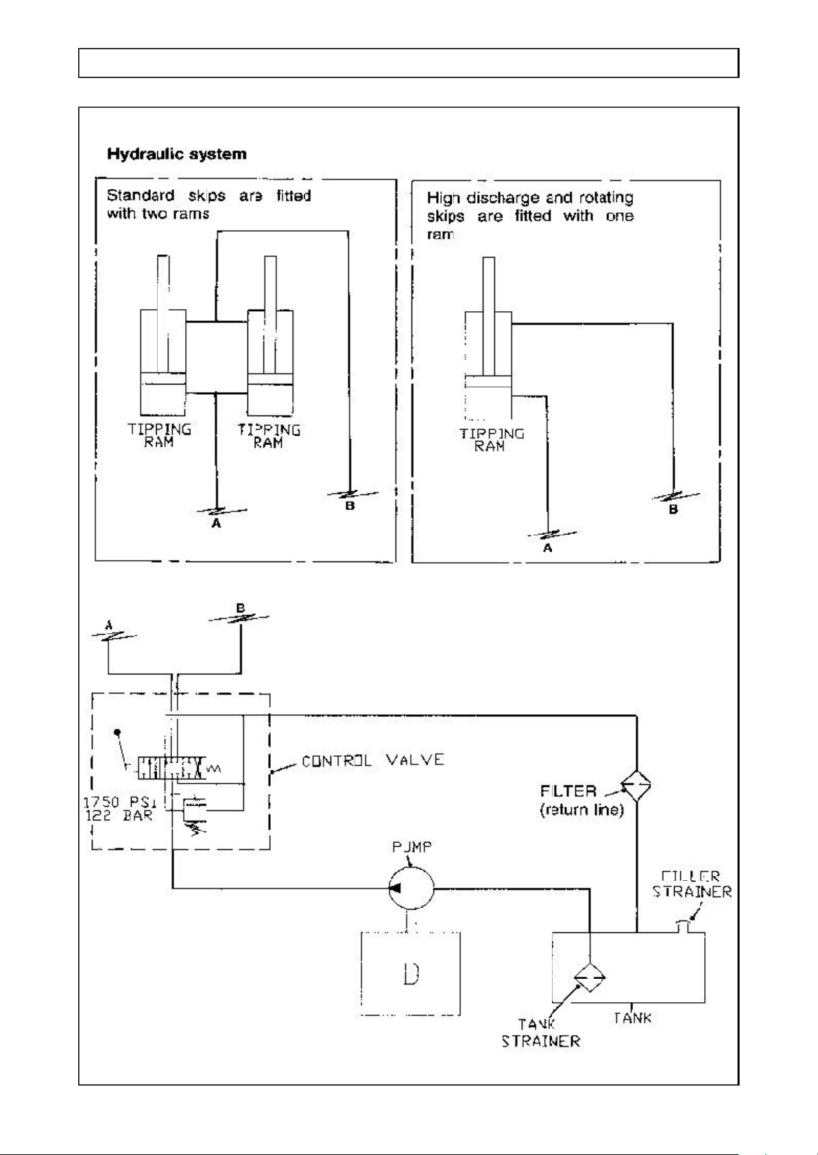
Description of hydraulic system
The hydraulic system provides power for
skip tipping.
The main components consist of:
Tank: The tank is filled through a
filler/strainer which incorporates an oil
level indicator. The filler cap is fitted with
a breather. In the bottom of the tank is a
suction strainer.
Pump: The pump is driven directly from
the engine.
Filter: The filter is situated in the return
to tank hose from the control valve.
Tipping control valve: The control valve
receives oil from the pump and delivers it
to the skip tipping rams. The rate of oil
flow to the rams is proportional to the
distance that the control valve lever is
moved.
If the control lever is held either fully
forward or backward after the rams have
reached their full stroke, a relief valve
opens, allowing the oil to return to the
tank.
It is illegal to dispose of waste
oil into drains or water
courses or to bury it.
Dumping hydraulic pressure
WARNINGAlways dump all hydraulic
pressure from the system
before servicing any hydraulic
component.
To dump pressure:
Stop the engine.
Move the skip control lever several
times in each direction.
Note: Hydraulically rotated skips
Hydraulically rotated skips on the 4B2000
utilise a load sensing steer valve and a
separate priority valve.
Page 40
SERVICE 3.14A
HYDRAULIC SYSTEM
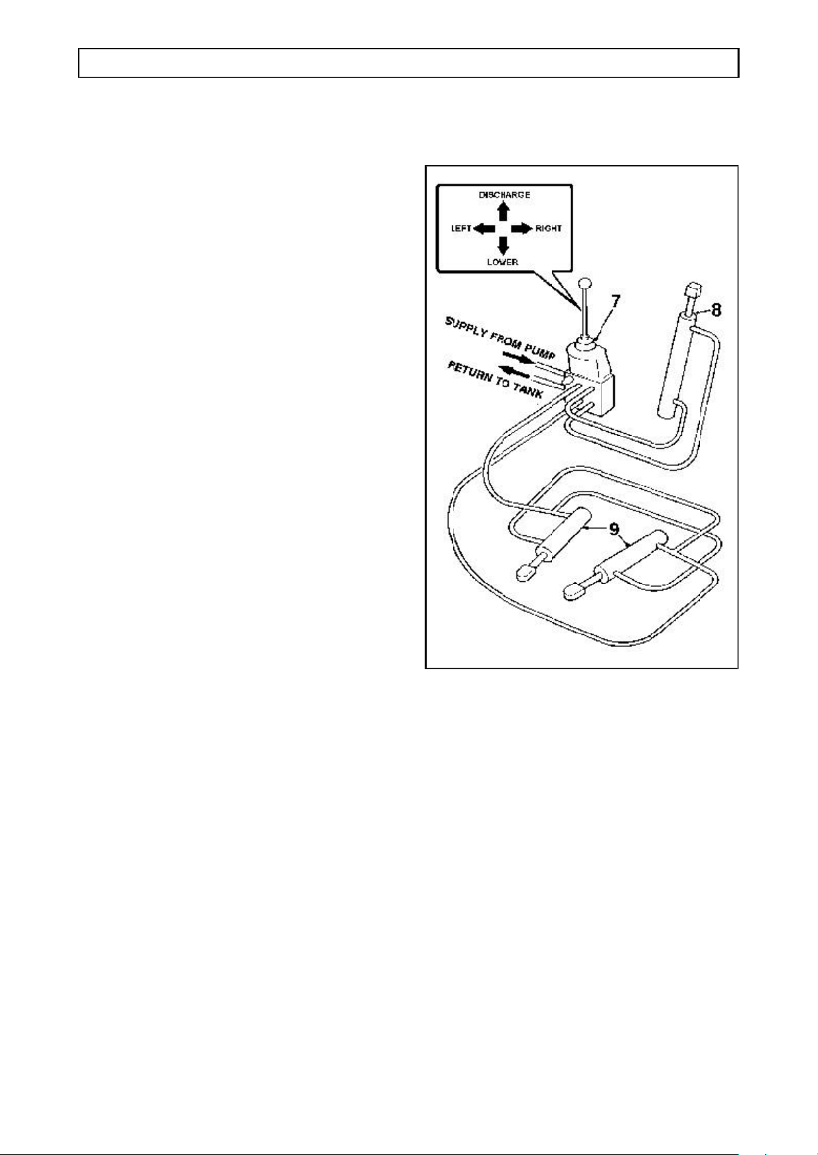
Dumpers with hydraulically
rotated skips
The tank, filter, pump and steering circuit
operate in basically the same manner as
for the conventional forward tipping skip.
(see the previous and following pages),
with the addition of a load sensing steer
valve and a separate flow priority valve.
Skip rotation
The skip is operated by a four-way
joystick control valve.
Joystick control valve: The control
valve (7) receives oil from the pump and
delivers it to either the tipping rams (8), or
the swivel rams (9). The rate of oil flow to
the rams is proportional to the distance
that the joystick lever is moved.
If the lever is held in one of its most
extreme positions (either left/right or
forwards/backwards, after any of the rams
have reached their full stroke, a relief
valve opens, allowing the oil to return to
the tank.
Because the joystick is fitted with a gate it
is not possible to move the lever
diagonally, therefore it is not possible to
tip and swivel simultaneously.
Page 41
SERVICE 3.15
HYDRAULIC SYSTEM
Page 42
Every 10 operating hours, or
3.16 SERVICE
HYDRAULIC SYSTEM
Hydraulic System Checks
If the hydraulic system fails to operate
completely, or does so extremely slowly,
carry out the following procedures.
Check that the hydraulic tank is full of oil
to the correct level. The level is correct
when oil is 50mm from the top of the filler
neck.
Check that the filter has been regularly
cleaned in accordance with the
maintenance schedule. If not, clean filter.
Check that the hydraulic pressures are
correct as follows:
Tipping circuit
Fit a 2000 lb/in2 gauge into the
hydraulic system at the base of a skip
ram.
Operate control lever to tip skip and
check the pressure reading on the
gauge when the rams are fully
extended and the relief valve is
‘blowing’. See “Specifications” for
correct pressure.
daily
Check hydraulic oil level
Do not check oil level before closing
the tipping rams, and the engine has
been stopped for 2 minutes.
Always clean the surrounding area before
removing the cap to prevent dirt from
entering the tank.
The oil level is correct when it is 50mm
(2”) from the top of the neck.
Do not overfill; it will cause leakage from
the breather!
First 100 operating hours
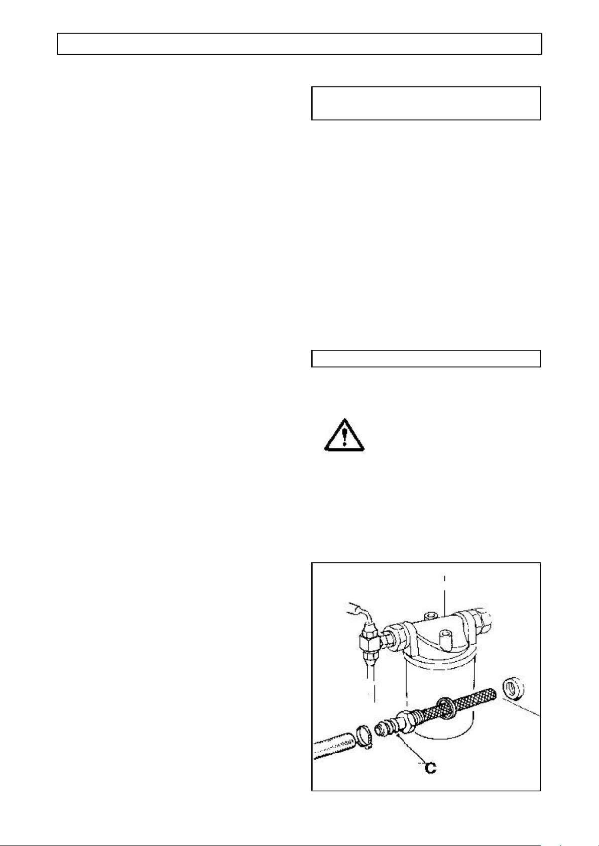
Clean / change tank strainer
WARNING Before cleaning the tank
strainer, stop the engine and
dump hydraulic pressure.
Steering circuit
Fit a 2000 lb/in2 gauge into the
hydraulic system at the base of the
steering ram.
Turn the steering wheel until the
machine is at ‘Full Lock’ and check the
pressure reading on the gauge. See
“Specifications” for correct pressure.
If these procedures do not correct the
fault, contact your Distributor.
Periodically check the hose between the
pump and the hydraulic tank to ensure
that it is not deformed. Any deformation
in the hose may result in a restricted flow
and damage to the pump.
Place a clean suitable container beneath
the hydraulic tank strainer. Clean the area
surrounding the strainer.
Disconnect the hose, then carefully
unscrew the strainer (C) from the tank
allowing the oil to drain into the container.
Page 43
SERVICE 3.17
HYDRAULIC SYSTEM
Provided that the oil does not become
contaminated it can be used to refill the
tank after the strainer has been cleaned
and replaced.
Wash the strainer in white spirit and
check it for any damage. If the strainer
cannot be thoroughly cleaned, fit a new
one.
Screw the strainer back into the tank.
Reconnect the hose.
Fill the tank with oil. (The oil level is
correct when it is 50mm below the top of
the filler neck. For the correct type of oil,
see “Specifications”.)
Run the engine to circulate the oil.
Operate the hydraulic control to purge any
air from the system.
Stop the engine and top up the tank as
required.
Every 300 operating hours
Change filter element
Change the filter element, using the
procedure described in the previous “First
100 operating hours”.
Every 1000 operating hours
Clean/change tank strainer
Clean or change the hydraulic tank
strainer (C), using the procedure
described in the previous “First 100
operating hours”.
Check the areas around the strainer for
leaks.
First 100 operating hours
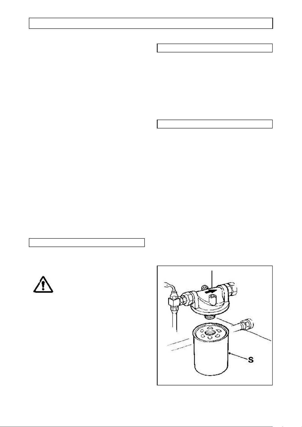
Change Hydraulic Filter Element
WARNINGBefore changing the filter
element, stop the engine and
dump hydraulic pressure.
Remove and discard element cartridge
(S). Clean joint area, wipe with hydraulic
oil, and fit new element cartridge. Do not
over tighten.
Run engine to circulate the oil.
Operate the hydraulic control to purge any
air from the system.
Stop the engine and top up the tank as
required. (For the correct type of oil, see
“Specifications”.)
Check the area around the element for
leaks.
Page 44

3.18 SERVICE
HYDRAULIC SYSTEM
Every 1000 operating hours
Change hydraulic oil
Run the engine and operate the
hydraulics to warm the oil.
Fully close the tipping rams.
Switch off the engine and dump hydraulic
pressure.
Clean the area surrounding the hydraulic
tank strainer and filler cap.
Place a suitable container on the ground
beneath the strainer to catch oil.
CAUTION: Before removing the strainer
be sure to stand to one side to avoid
the oil that will spill from the hole.
Carefully remove the strainer and drain
the oil from the tank.
Flush out the tank with clean hydraulic oil,
taking extreme care to remove all dirt and
foreign matter.
Refit the strainer.
Clean the filler cap breather.
Refill the tank with clean oil of the correct
type and grade. For the correct type of oil,
see “Specifications”.
Run the engine to circulate the oil.
Operate the hydraulic control to purge any
air from the system.
Stop the engine and top up the tank as
required.
Check the area around the strainer for
leaks.
Page 45
SERVICE 3.19
GREASING
Every 50 operating hours, or
weekly
WARNING Always use lubricants of the
grade specified.
Always lubricate and service
BEFORE work commences,
and WITHIN the periods
specified.
Grease points
Clean nipples BEFORE and
AFTER greasing. Apply the
grease gun until clean grease
appears.
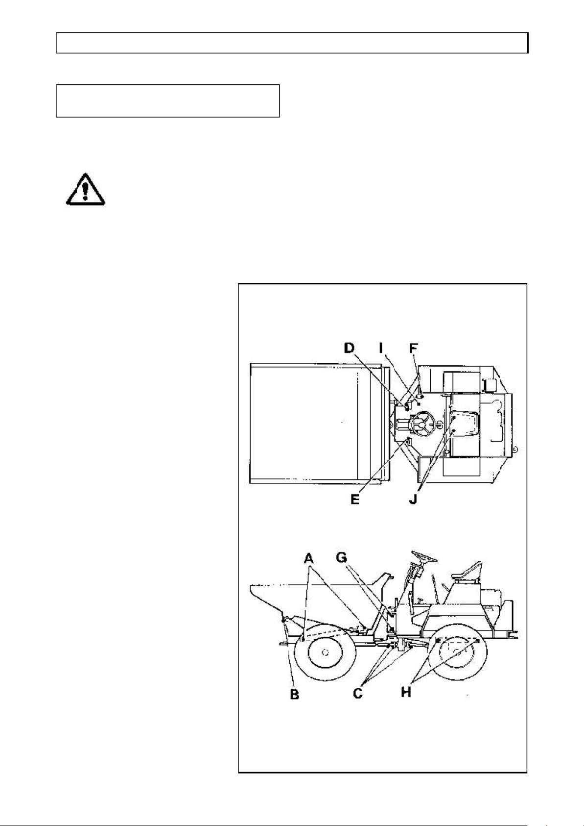
Location of grease points
A Tipping rams (2 on each ram)
[No grease points on Rotating
or High discharge skip tipping
rams]
B Skip pivots (2)
C Propeller shaft (3)
D Brake pedal pivot (2)
E Clutch pedal pivot (2)
F Accelerator pivot (2)
G Front/rear chassis centre
pivot (2)
H Rear axle centre pivot (2)
I Handbrake cable (1)
J Gearbox clutch shaft pivot (1
each side of gearbox bell-
housing)
# Clean and lubricate all
linkages not fitted with a
grease nipple.
Page 46
3.20 SERVICE
BRAKING SYSTEM
Salisbury axles
Brake System
The service brakes consist of calipers
acting upon dry discs.
The brake system is designed to require
the minimum of maintenance, and
providing the hydraulic fluid in the
reservoir is not allowed to fall below the
recommended level, no defects should
normally occur.
Fluid loss must be supplemented by
topping up the reservoir with brake fluid
that conforms to SAE. J1703. No other
fluid may be used.
If air is present in the system, it will be
indicated by sluggish response and by
spongy action of the brake pedal. This
may be due to air being introduced at a
loose joint or by the reservoir fluid level
being allowed to fall very low. These
defects must be remedied immediately
and the complete system bled.
F Lock both bleed screws and top up
reservoir to the correct level.
G Apply normal working load on brake
pedal for two or three minutes and
examine entire system for leaks.
Note: During operation it is essential
that the reservoir levels are kept
topped up to prevent further air being
drawn into the system. Only use new
fluid for topping up.
To bleed the system, proceed as
follows:
A Check that all connections are tight and
all bleed screws are closed.
B Fill reservoir with the correct fluid.
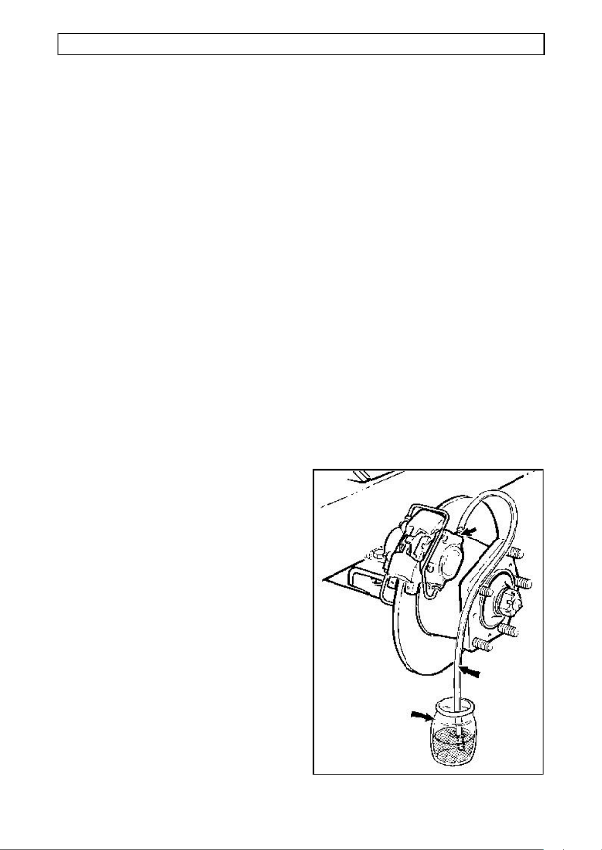
C Attach bleeder tube (1) to one of the
bleed screws (2) and immerse other
end in a small quantity of brake fluid
contained in a glass jar (3).
Slacken bleed screw and operate brake
pedal up and down to its full stroke until
fluid pumped into jar contains no air
bubbles. Hold down pedal and close
bleed screw.
Remove bleeder tube and release
pedal.
D Repeat on other caliper.
E Continue until all air has been bled from
the system.
Page 47
SERVICE 3.21
BRAKING SYSTEM
Newage axles
Brake System
The service brakes consist of totally
sealed oil immersed multi-discs fitted
within the front axle. (The rear axle only
has brakes fitted as an option.)
The brake system is designed to require
the minimum of maintenance, and no
defects should normally occur.
If air is present in the system, it will be
indicated by sluggish response and by
spongy action of the brake pedal.
To bleed the system, proceed as
follows:
A Check that all connections are tight and
the bleed screws are closed.
B Check that there is sufficient oil in the
hydraulic tank.
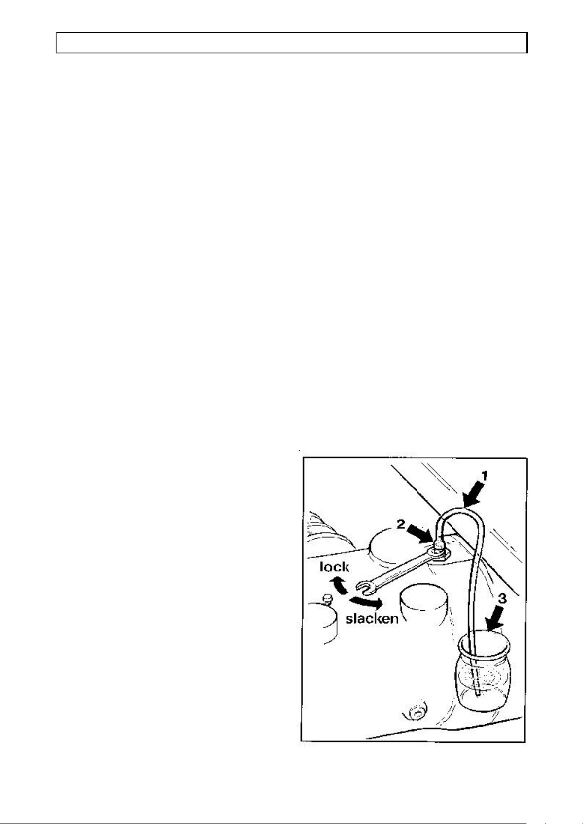
C Attach bleeder tube (1) to the bleed
screw (2) on the front axle and immerse
the other end of the tube in a small
quantity of hydraulic oil contained in a
glass jar (3).
Slacken bleed screw and depress the
brake pedal to its full extent. Hold the
pedal down and tighten bleed screw.
Release pedal and wait 5 to 10
seconds. Slacken the bleed screw and
repeat process until the oil pumped into
the jar contains no air bubbles. Hold
down the pedal and close the bleed
screw.
Remove bleeder tube and release
pedal.
Note: Always ensure that free play of 1
to 2 mm exists between the master
cylinder push rod and the piston when
the brake pedal is released.
D Lock the bleed screw.
F If the dumper is fitted with four wheel
braking, repeat the above procedure on
the rear axle.
G Apply normal working load on brake
pedal for two or three minutes and
examine the entire system for leaks.
Check the oil level in the hydraulic tank.
Page 48
3.22 SERVICE
WHEELS & TYRES
Every 10 operating hours, or
daily
Wheel nuts
Tighten wheel nuts whenever necessary,
every ten hours or daily.
After a wheel change, the nuts should be
checked several times a day until they
maintain their correct setting.
For wheel nut tightening torque, see
“Specifications”.
Every 50 operating hours, or
weekly
Tyre pressures
WARNINGALWAYS ensure that when
adding air to a tyre the area is
clear of personnel.
NEVER over-inflate a tyre
beyond its specified pressure.
NEVER adjust the tyre
pressure in an attempt to
improve traction on soft
ground or obtain a softer ride
on hard ground. Incorrectly
adjusted tyres can affect the
steering and handling
characteristics.
Check the tyre pressures only when the
tyres are cold.
For correct pressures see “Specifications”.
Tyre condition
Check the tyres for damage and
deterioration.
Page 49
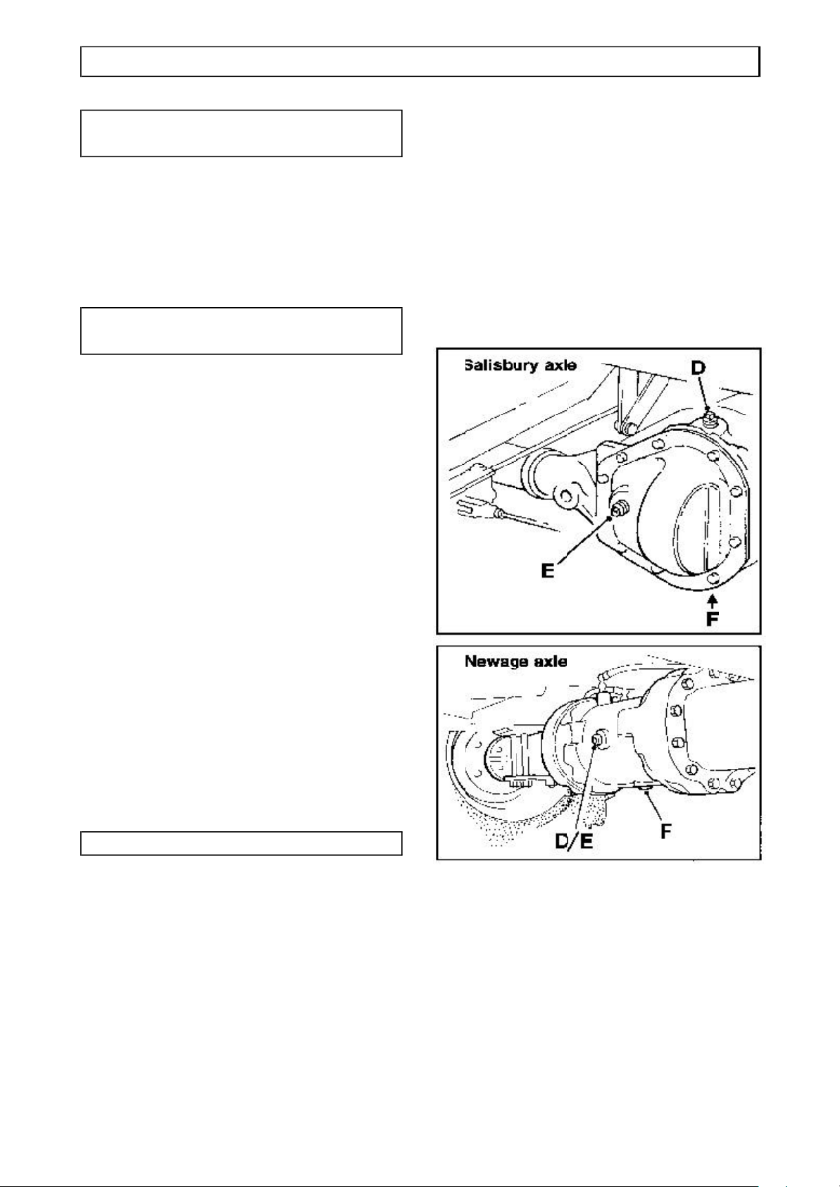
SERVICE 3.23
AXLES
Every 10 operating hours, or
daily
Check for leaks
Check for oil leaks around joints and
seals.
Every 50 operating hours, or
weekly
Tighten securing nuts
Tighten axle arm/main case joint securing
nuts and half shaft nuts.
Axle oil level
Do not check the oil level until the
machine has stood for 2 minutes.
Clean the area surrounding level plug (E)
before removing it.
The oil is correct when level with the
bottom of the level plug hole.
If the level is low, top-up with clean oil of
the correct grade through the filler (D).
Replace plugs.
For the correct type and grade of oil, see
“Specifications”.
Every 1000 operating hours
Axle oil change
Change the lubrication oil in the front axle
as follows:
Clean the area surrounding the filler (D),
level (E) and drain (F) plugs.
Place a suitable container beneath the
drain plug.
CAUTION: Before removing the plugs be
sure to stand to one side to avoid the oil
that will spill from the drain hole.
Remove drain plug (F) and drain oil from
the casing. Replace drain plug.
Refill at the filler plug (D) with clean oil of
the correct grade.
The level is correct when oil reaches the
bottom of the level plug hole (E) .
Replace all plugs.
For the correct type and grade of oil, see
“Specifications”.
Page 50

3.24 SERVICE
Page 51
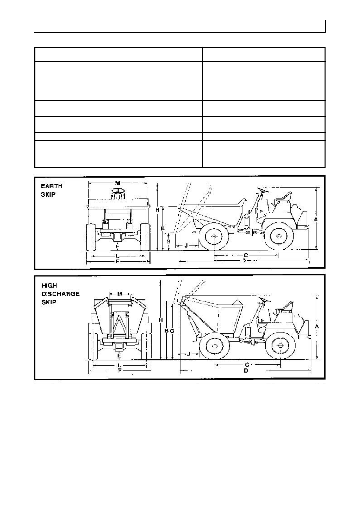
TECHNICAL INFORMATION 4.1
DIMENSIONS
Machine Model Earth skip High discharge
A Overall height 1.83 m 1.83 m
B Skip loading height 1.33 m 1.55 m
C Wheel base 1.79 m 1.79 m
D Overall length 3.55 m 3.27 m
E Ground clearance 0.20 m 0.20 m
F Overall width 1.76 m 1.76 m
G Skip discharge height 0.57 m 1.45 m
H Maximum skip height when tipped 2.31 m 2.73 m
J Skip discharge forward of tyres 0.56 m 0.32 m
L Track 1.53 m 1.53 m
M Skip discharge width 1.42 m 0.67 m
Rear axle articulation 0.30 m 0.30 m
Turning circle 7.45 m 7.45 m
Page 52
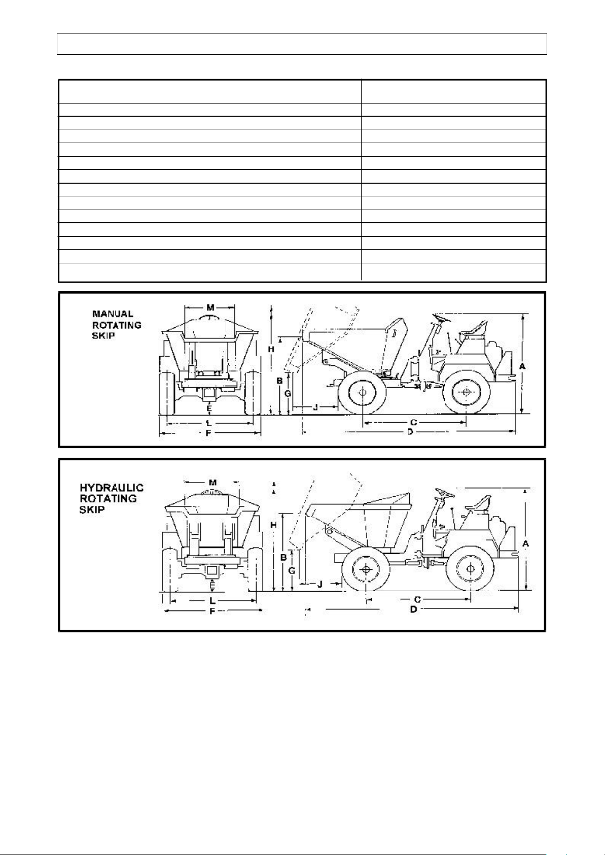
4.1A TECHNICAL INFORMATION
DIMENSIONS
Machine Model Manual rotating skip Hydraulic rotating skip
A Overall height 1.83 m 1.83 m
B Skip loading height 1.44 m 1.35 m
C Wheel base 1.79 m 2.10 m
D Overall length 3.71 m 3.67 m
E Ground clearance 0.20 m 0.20 m
F Overall width 1.76 m 1.76 m
G Skip discharge height 0.57 m 1.33 m
H Maximum skip height when tipped 2.48 m 2.77 m
J Skip discharge forward of tyres 0.71 m 0.30 m
L Track 1.53 m 1.53 m
M Skip discharge width 0.51 m or 1.07 m 1.40 m
Rear axle articulation 0.30 m 0.30 m
Turning circle 7.45 m 8.20 m
Page 53

4.2 TECHNICAL INFORMATION
SPECIFICATIONS
ENGINES
up to 1985 Petter PH2: “See relevent Engine Operator’s handbook”.
Lister ST2: “See relevent Engine Operator’s handbook”.
1985 to 1989 Lister-Petter PH2: “See relevent Engine Operator’s handbook”.
1985 to 1989 Lister-Petter TS2
1989 to date Lister-Petter TR2: Twin cylinder, direct injection, naturally aspirated,
flywheel fan air cooled diesel.
Rotation: Anti-clockwise when looking on the flywheel.
TS2: Output: 15.6 kW (20.9 bhp) @ 2500 rev/min.
TR2: Output: 19 kW (25.4 bhp) @ 2500 rev/min.
NOTE: FROM 1989 TO DATE THE LISTER-PETTER TS2 HAS BEEN OFFERED AS AN OPTION.
ELECTRICS (Where fitted) 12 volt negative earth.
FUEL SYSTEM System: Two element fuel pump.
Fuel specification: BS 2869:1988 Class A2, or BS EN590:1995 Class A1
Fuel tank capacity: 29.5 litres
Fuel filter: Strainer within fuel tank.
Air cleaner: Renewable element.
AXLES Front & rear: Heavy duty with fully floating half shafts.
(Newage)
BRAKES Service: Front axle braking. Totally sealed oil immersed
multi-plate disc brakes, featuring fully automatic
adjustment for wear.
(Optional rear axle braking).
Parking: Hand operated, ratchet type, actuating a disc brake
caliper mounted on the transmission.
TRANSMISSION Heavy duty constant mesh gearbox, with 3 forward and 1 reverse gear.
HYDRAULICS Pump: Gear type.
Control valve: Sectional or monobloc with pressure relief valve.
Filter: Strainer within the hydraulic tank, plus an in-line filter.
Page 54

TECHNICAL INFORMATION 4.3
SPECIFICATIONS
ROAD SPEEDS
1st Gear 2nd Gear 3rd Gear Reverse
Km/h (mph) km/h (mph) km/h (mph) km/h (mph)
Petter PH2
3.6 (2.2) 8.4 (5.2) 16.1 (10.0) 4.0 (2.5)
Lister ST2 and Lister-Petter TS/TR2
4.3 (2.7) 10.0 (6.2) 18.5 (11.5) 4.8 (3.0)
LUBRICANTS AND FLUIDS Total oils (factory fill) Capacities
TS/TR2 Engine Lub. Oil Rubia H 10W/30 2.7 litres
Note: For engine oils used in temperatures above 30oC consult the Engine Handbook.
Gearbox Rubia B 20W/30 2.0 litres (approx)
Transfer Box EP85W/140 or EP140 gear oil 1.00 litre (approx)
Axles (Newage, with brakes) Universal plant oil or Transmission MP 3.5 litres
(Newage, without brakes) ” 2.5 litres
(Salisbury) Gear oil SAE 90 EP -----
Brake System (Supplied from hydraulic tank) Azzola ZS46 -----
Hydraulic System Azzola ZS46 29.5 litres (tank)
General Grease Multis EP2 as required
General Lubrication Oil Rubia B 20W/30 as required
TYRE PRESSURES
Front 2.35 bar (35 lb in2)
Rear 2.35 bar (35 lb in
2)
TYRES
Newage Axles
Standard 11.5/80 x 15
ADJUSTMENTS
Wheel nuts torque 200 lbf ft (271 Nm)
Engine (See Engine Workshop Manual)
HYDRAULIC PRESSURE
120.7 bar (1750psi)
138 bar (2000psi) hyd. rotating skips only
Alternative 7.5 x 16
(not to be used on rotating skips)
Salisbury Axles (Obsolete)
10/75 x 15
Page 55
4.4 TECHNICAL INFORMATION
SPECIFICATIONS
CAPACITIES
SKIP TYPE
Standard High discharge Rotating
Payload 2000 kg 2000 kg 1630 kg (up to serial no.1092)
2000 kg (from serial no.1093)
Water level 850 litres 760 litres 935 litres
Struck 1100 litres 800 litres 992 litres
Heaped 1500 litres 1207 litres 1304 litres
MACHINE WEIGHTS
MODEL, skip type
Standard High discharge Manual rotating skip
1739 kg 1875 kg 1857 kg
VIBRATION DECLARATION Whole body vibration level a
w
(m/s
2
) :- 0.7 - 0.8 Typical*
* Note: The absence of a harmonised test code together with the variable conditions under
which this equipment may be used allows only representative figures to be quoted.
Hand/arm vibration level a
(m/s2) :- Less than 2.5
ha
(Vibration declaration applicable only to EEC models)
Page 56
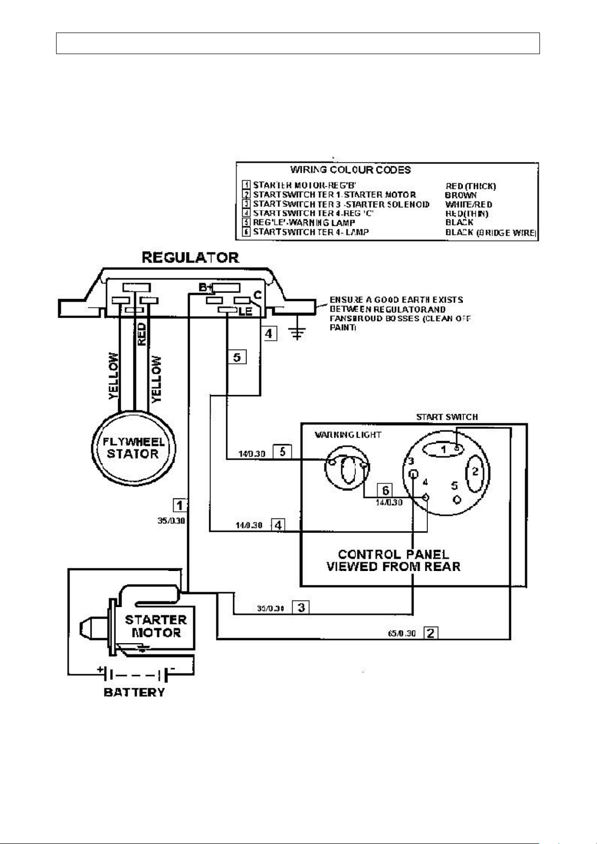
TECHNICAL INFORMATION 4.5
MAIN ELECTRICAL CIRCUIT (without road lights)
Later dumpers with Lister-Petter ‘NISCA’ charging system
Page 57
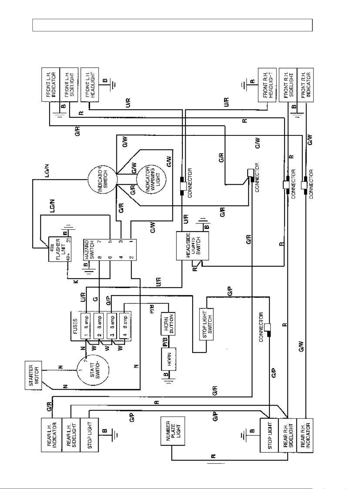
4.6 TECHNICAL INFORMATION
ROAD LIGHTS ELECTRICAL CIRCUIT
4B2000 dumpers from serial number 0863
Page 58
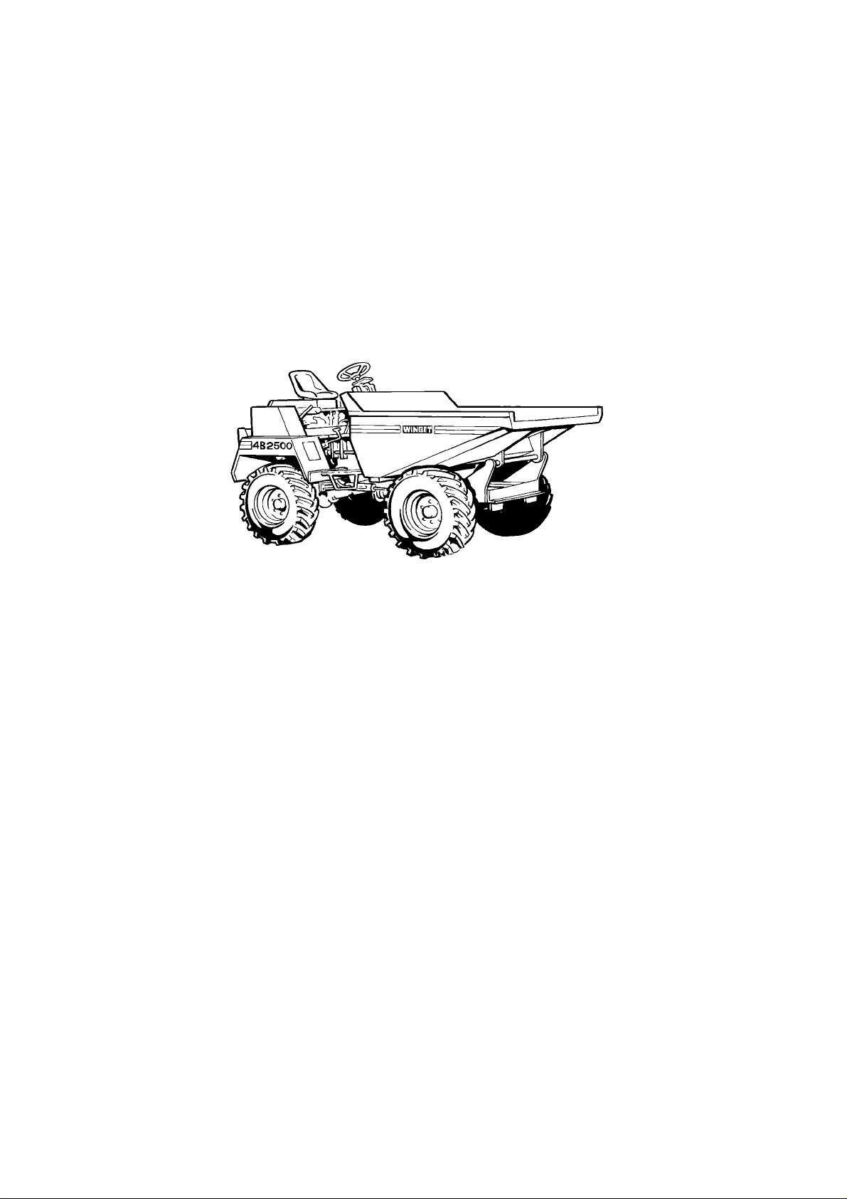
Contents
4B2000
4B2000
4B20004B2000
DUMPERS
DUMPERS
DUMPERSDUMPERS
A CHASSIS & SKIPS
B AXLES & STEERING
C TRANSMISSIONS
D BRAKES
E ENGINES
F ELECTRICS
H HYDRAULICS
J DECALS
K NUMERICAL INDEX
Page 59

Chassis, Panels
& Skips
CHASSIS
Non hydraulic rotating skip
CHASSIS, front
Hydraulic rotating skip
BATTERY CARRIER A - 2
SKIPS
Earth & concrete
Rotating, manually operated A - 4
Rotating, hydraulically operated A - 4A
High discharge A - 5
A - 1
A - 1A
A - 3
PANELS A - 6
R.O.P.S. FRAME A - 10
SEAT "KAB" A - 11
Page 60
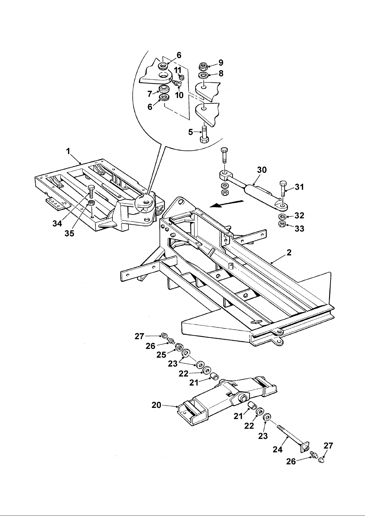
A - 1 4B2000 Dumper
Page 61

CHASSIS A - 1
Item Part no Serial no Description Qty
1 40100A33
1 40100A32
2 40101A05
2 40101A06
CHASSIS, front (to fit Salisbury axle)
CHASSIS, front (to fit Newage axle)
CHASSIS, rear (to fit Salisbury axle)
CHASSIS, rear (to fit Newage axle)
5 10375A07 BOLT 2
6 10609A02 SPACER, tapered 4
7 460214 BEARING 2
8 10S43 WASHER 2
9 107S11 NUT 2
10 131S02 NIPPLE, grease 2
11 176S01 CAP, grease nipple 2
20 30188A05 / 1092 FRAME, axle pivot 1
20 30188A06 1093 / FRAME, axle pivot 1
21 10938A01 BUSH 2
22 43529C WASHER, centre, 'bronze' 2
23 ASE178 WASHER, thrust 4
24 20161A07 PIN, pivot 1
25 107S23 NUT, self-locking 1
1
1
1
1
26 131S03 / 0745 NIPPLE, grease, push-in 2
26 131S01 0746 / NIPPLE, grease, threaded 2
27 176S01 CAP, grease nipple 2
30
………………..
RAM, steering (see Hydraulic Section)
31 10599A01 BOLT, steering ram 2
32 67S13 WASHER 2
33 10600A01 NUT, steering ram 2
34 11S07P BOLT, skip stop 2
35 7S07 NUT 2
1
V601140 / Dec '10
Page 62
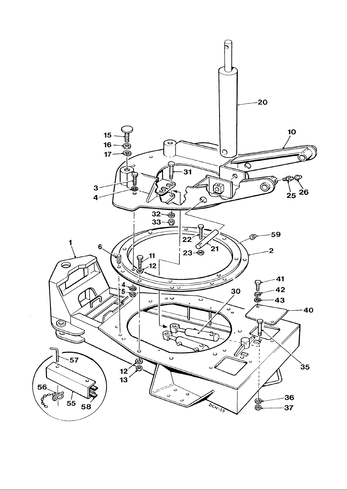
A - 1A 4B2000 Dumper
Page 63

CHASSIS, Hydraulic rotating skip A - 1A
Item Part no Serial no Description Qty
1 V2004770 CHASSIS, front, rotating skip 1
2 10640A03 RING, bearing 1
3 11S05E SCREW, set 8
4 267S07 WASHER, flat 16
5 61S05 NUT, “Binx”, self-locking 8
6 54S08J PIN, roll 4
10 V2004145 FRAME, rotating 1
11 11S05E SCREW, set 6
11A 11S05F
12 267S07 WASHER, flat 16
13 61S05 NUT, “Binx”, self-locking 10
15 V2004234 SCREW, skip stop 2
16 7S08 NUT 2
17 17S11 WASHER, spring 2
SCREW, set (not illustrated)
4
20 30113A06 RAM, tipping 1
21 10720A02 Pin, ram base pivot 2
22 11S03M SCREW, set 2
23 61S03 NUT, “Binx”, self-locking 2
25 131S01 NIPPLE, grease 2
26 176S01 CAP, grease nipple 2
30 30287A03 RAM, rotating 2
31 6S07MM BOLT, (rotating ram eye) 2
32 10S06 WASHER, flat 6
33 107S18 NUT, “Nyloc” self-locking 2
35 6S07V BOLT, (rotating ram base) 2
36 10S06 WASHER, flat 6
37 107S18 NUT, “Nyloc”, self-locking 2
40 V2004494 COVER 2
41 11S03B SCREW,set 4
42 17S04 WASHER, spring 4
43 267S05 WASHER, flat 4
55 V2004212 SAFETY SUPPORT, tip ram 1
56 902S02 PIN, lynch, c\w chain 2
57 V2004217 PIN 2
58 106209000
59 176S01 CAP, grease nipple
V601140 / July '02
SEAL, strip, (2 meters)
1
Page 64
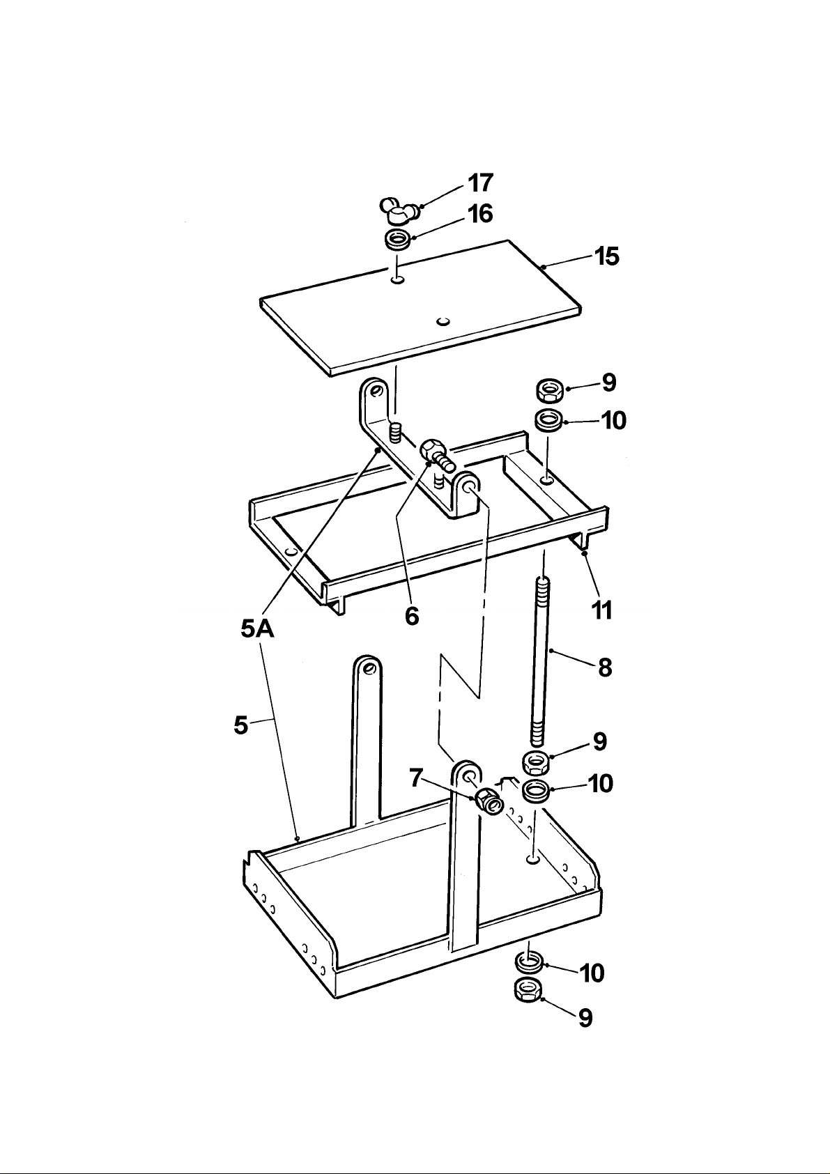
A - 2 4B2000 Dumper
Page 65

BATTERY CARRIER A - 2
Item Part no Serial no Description Qty
5 30080A03 CARRIER, battery 1
5A 30080A0303 BAR, locking 1
6 11S04C SCREW, set 2
7 59S03 NUT, 'Nyloc' self-locking 2
8 40SA17 TIE BAR 2
9 9S01 NUT 6
10 267S04 WASHER, flat 6
11 10559A01 CLAMP, battery 1
15 10742A05 COVER, battery 1
16 267S04 WASHER, flat 2
17 177S03 NUT, wing 2
V601140 / issue 02 0800
Page 66
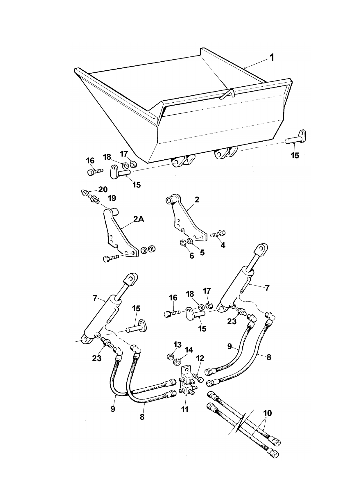
A - 3 4B2000 Dumper
Page 67

SKIP, earth & concrete A - 3
3
3
Item Part no Description Qty
1 40089A04
1 40275A02
Serial no
SKIP, concrete, 0.96 m
SKIP, earth, 0.85 m
1
1
2 30126A10 BRACKET, R.H., skip support 1
2A 30126A11 BRACKET, L.H., skip support 1
4 8S06G BOLT 8
5 267S09 WASHER, flat 8
6 59S11 NUT, self-locking 8
7 -------------
RAM, skip tip (see pages H-6 & H-6A)
2
8 33S02H HOSE, 470mm long 2
8 33S02J HOSE, 570mm long, ram retract 2
9 31S02GG HOSE, bracket to ram extend 2
10 35S02AG HOSE, bulkhead to bracket 2
11 435388 BRACKET, Tee pieces 1
12 11S02C BOLT 1
13 7S02 NUT 1
14 17S03 WASHER, spring 1
15 10470A02 PIN, pivot 4
16 11S04E SCREW, set 4
17 7S04 NUT 4
18 17S05 WASHER, spring 4
19 131S03 / 0745
19 131S01 0746 /
NIPPLE, grease, push-in
NIPPLE, grease, threaded
20 176S01 CAP, grease nipple 2
23 122S03 FITTING, adaptor 2
2
2
V601140 / issue 02 0800
Page 68
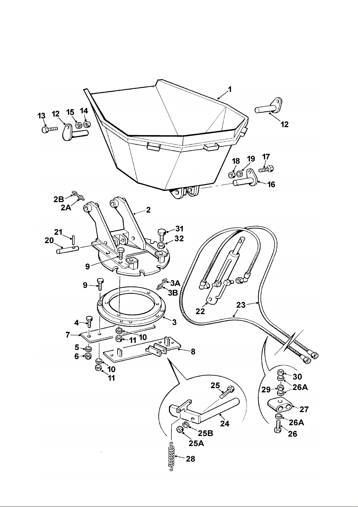
A - 4 4B2000 Dumper
Page 69

SKIP, Manual rotating A - 4
..….
..….
…………..….
…………..….
……
……
Item Part no Serial no Description Qty
40312A01 SKIP, 508mm mouth, asembly
40312A02 SKIP, 1067mm mouth, asembly
1 40217A01 SKIP, 508mm mouth 1
1 40217A02 SKIP, 1067mm mouth 1
2 40116A03 FRAME, skip 1
2A 131S01 NIPPLE, grease 2
2B 176S01 CAP, grease nipple 2
3 10640A02 RING, slewing turntable 1
3A 176S01 CAP, grease nipple 4
3B
4 8S05D BOLT 4
5 267S07 WASHER, flat 8
6 59S04 NUT, nylon insert 4
7 10833A04 PLATE, front mount 1
8 30306A01 PLATE, rear mount 1
9 8S05E BOLT 4
10 267S07 WASHER, flat 8
11 59S04 NUT, nylon insert 4
12 10522A04 PIN, skip pivot 2
13 11S04C SCREW, set 2
14 7S04 NUT 2
15 17S05 WASHER, spring 2
16 10919A01 PIN, ram upper pivot 1
17 11S04C SCREW, set 1
18 7S04 NUT 1
19 17S05 WASHER, spring 1
20 10720A02 PIN, ram lower pivot 1
21 55S07Q PIN, tension 1
NIPPLE, grease 4
22
RAM, hyd (see Hydraulics Section) 1
23 31S02K HOSE, ram to bulkhead 2
24 40296A03 CATCH, skip locking 1
25 8S05H BOLT 1
25A 59S04 NUT, 'Nyloc' self-locking 1
25B 267S07 WASHER, flat 1
26 11S02H SCREW, set 1
26A 267S04 WASHER, flat 3
27 187S08JJ CLAMP, hose 1 pair
28 C173D SPRING, skip catch 2
29 7S02 NUT 1
30 61S02 NUT, 'Binx' self locking 1
31 11S07P SCREW, set 2
32 7S07 NUT 2
V2003111
V2003253
TIE, nylon (not illustrated)
TIE, nylon (not illustrated)
V601140 / issue 02 0800
2
1
Page 70
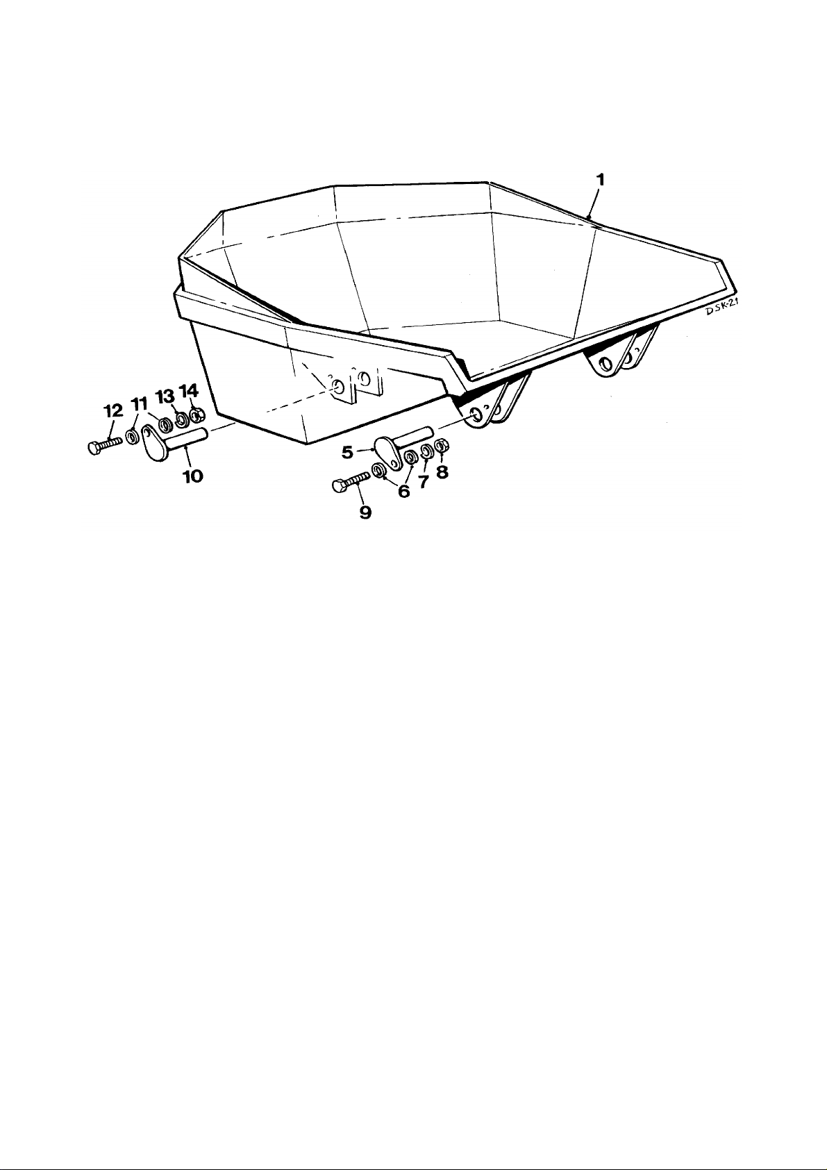
A - 4A 4B2000 Dumper
Page 71

SKIP, Hydraulic rotating A - 4A
Item Part no Serial no Description Qty
1 V2004449 SKIP, rotating, hydraulically swivelled 1
5 10522A04 PIN, skip pivot 2
267S06 WASHER, flat 4
6
17S05 WASHER, spring 2
7
8 7S04 NUT 2
9
11S04C SCREW, set 2
10 10919A01 PIN, ram pivot 1
267S06 WASHER, flat 2
11
12 11S04C SCREW, set 1
17S05 WASHER, spring
13
14 7S04 NUT 1
1
V601140 / July '02
Page 72
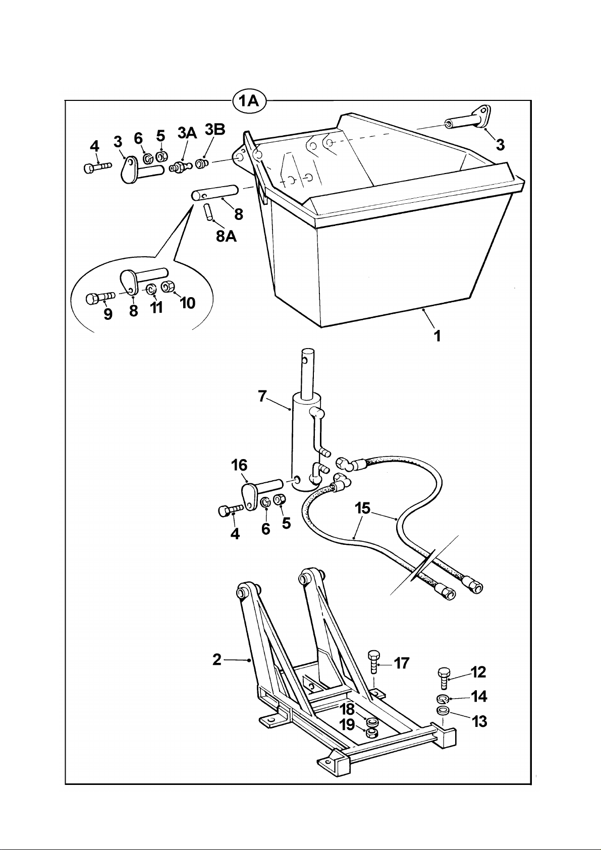
A - 5 4B2000 Dumper
DSK-3
Page 73

SKIP, high discharge A - 5
…………..….
Item Part no Serial no Description Qty
1A 40313A01 SKIP, high discharge, assembly 1
1 40299A01 SKIP, high discharge 1
2 40252A02 FRAME 1
3 10932A01 PIN, skip pivot 2
3A 131S01 NIPPLE, grease 2
3B 176S01 CAP, grease nipple 2
4 11S04C SCREW, set 3
5 7S04 NUT 3
6 17S05 WASHER, spring 3
7
RAM, hyd (see Hydraulics Section)
8 10919A02 / July 90 PIN, ram upper pivot 1
8 10919A04 July 90 / PIN, ram upper pivot 1
8A 55S07T July 90 / PIN, spirol 1
9 11S03C SCREW, set 2
10 7S03 NUT 2
11 17S04 WASHER, spring 2
12 11S07K SCREW, set 4
13 267S10 WASHER, flat 4
14 17S09 WASHER, spring 4
15 31S02P HOSE, bulkhead to ram 2
16 10919A03 PIN, ram lower pivot 1
17 11S05F SCREW, set 2
18 267S07 WASHER, flat 2
19 59S04 NUT, 'Nyloc' self-locking 2
1
V601140 / issue 02 0800
Page 74
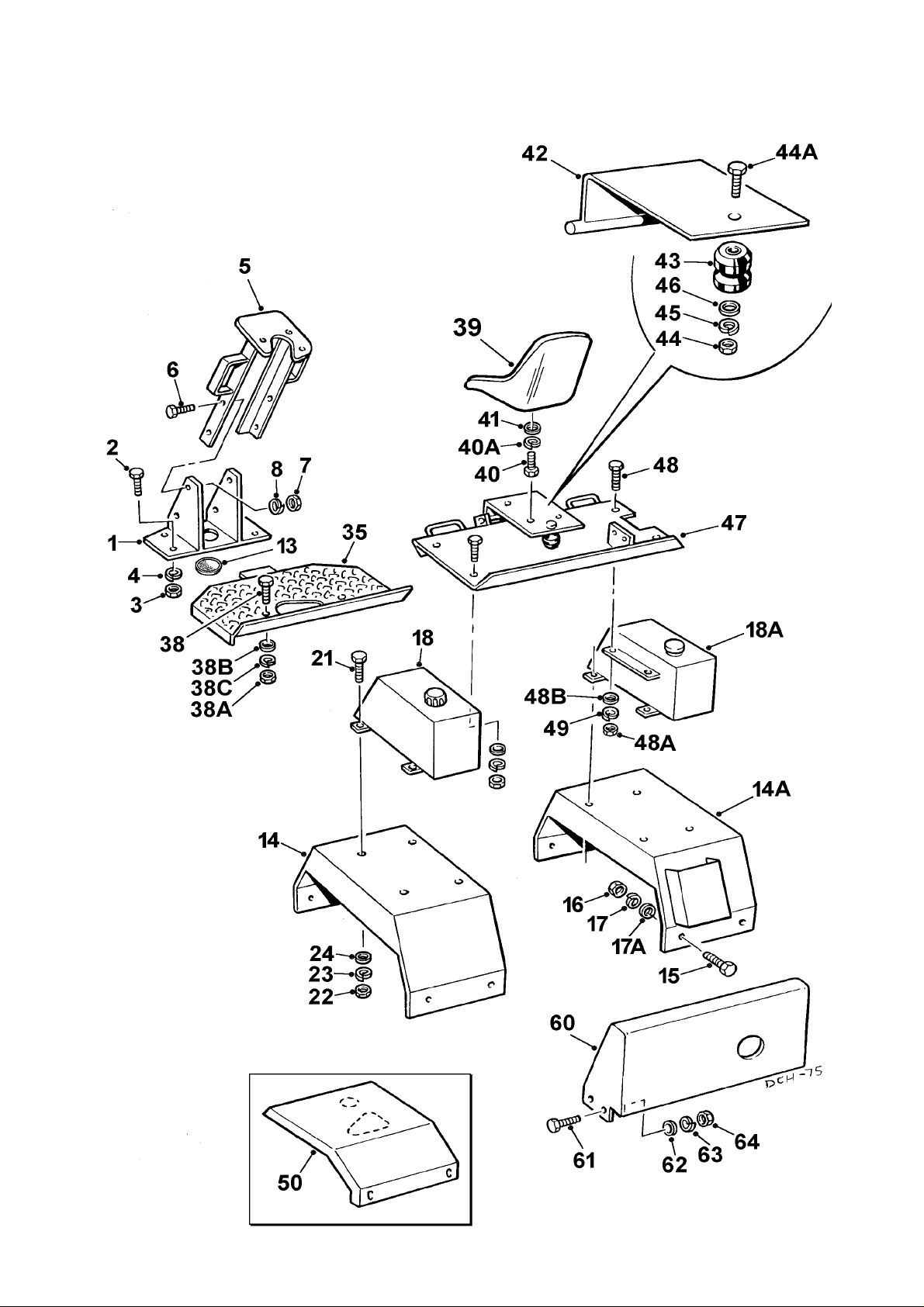
A - 6 4B2000 Dumper
Page 75

PANELS A - 6
…………..
Item Part no Serial no Description Qty
1 30184A02 PLATE, mounting 1
2 11S04C SCREW, set 4
3 7S04 NUT 4
4 17S05 WASHER, spring 4
5 30125A02 SUPPORT, steering column 1
6 11S04C SCREW, set 4
7 7S04 NUT 4
8 17S05 WASHER, spring 4
13 435375 GROMMET 1
14 40280A11 MUDWING, L.H. 1
14A 40279A04 MUDWING, R.H. 1
15 11S04C SCREW, set 8
16 7S04 NUT 8
17 17S05 WASHER, spring 8
17A 267S06 WASHER, flat 8
18 40282A04
18A
TANK, hydraulic (see page H - 1)
TANK, fuel (see page E - 1A)
21 11S04C SCREW, set 8
22 7S04 NUT 8
23 17S05 WASHER,spring 8
24 267S06 WASHER, flat 8
35 30163A06 PLATE, floor 1
38 11S04C SCREW, set 2
38A 7S04 NUT 2
38B 267S06 WASHER, flat 2
38C 17S05 WASHER, spring 2
39 20072A01
SEAT (OBSOLETE: use V2000954)
39 V2000954 SEAT 1
NOTE: When replacing seat 20072A01 with V2000954, refer
to Bulletin SB2 (August 1991) for fitting instructions.
1
1
40 11S03B SCREW, set 4
40A 17S04 WASHER, spring 4
41 267S05 WASHER, flat 4
V601140 / issue 02 0800 continued >
Page 76
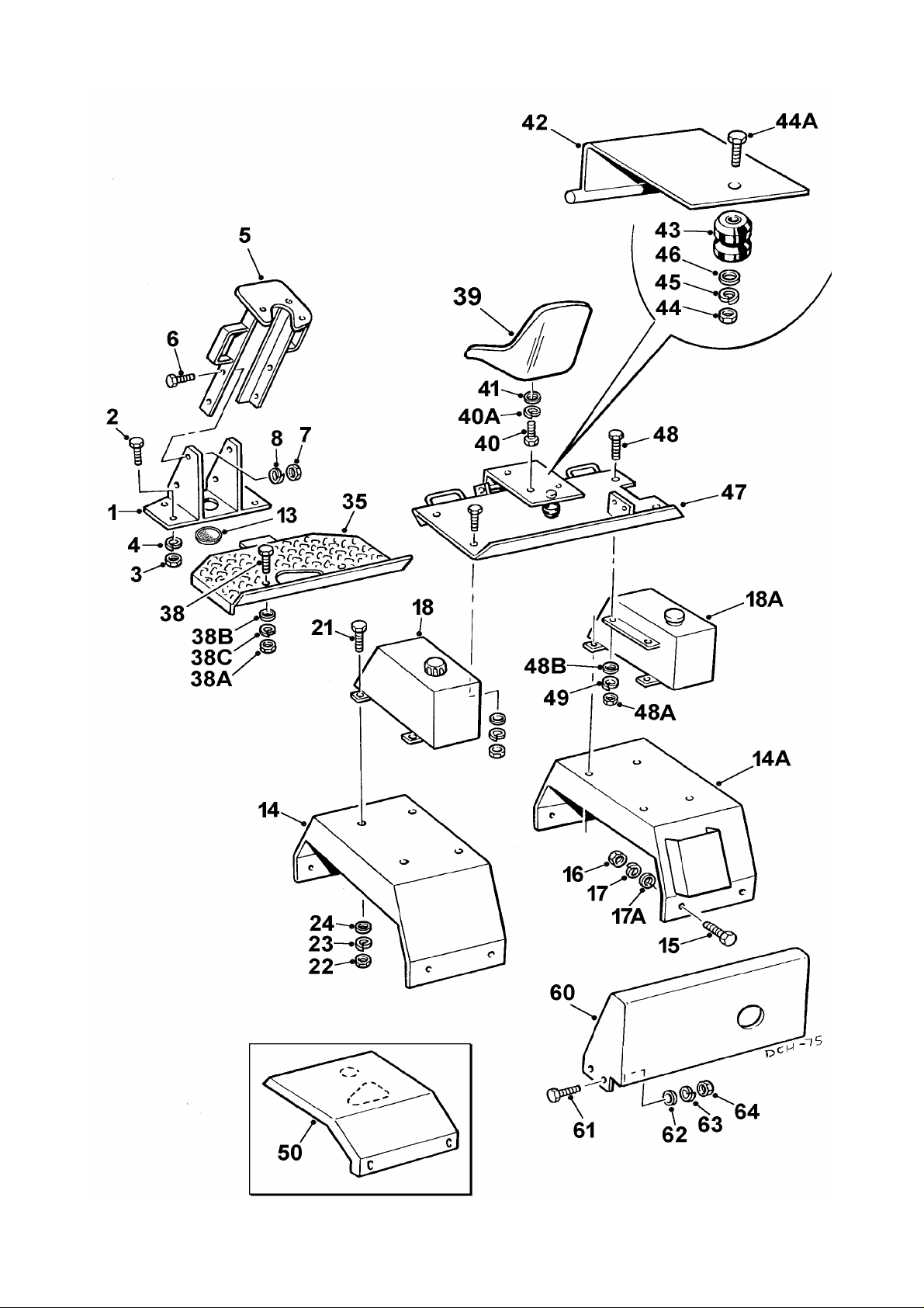
A - 6 4B2000 Dumper
Page 77

PANELS A - 6
Item Part no Serial no Description Qty
42 30148A06 FRAME, seat 1
43 10519A01 SPRING, rubber 1
44 7S04 NUT 1
44A 206S03C SCREW, counter sunk 1
45 17S05 WASHER,spring 1
46 C180B WASHER, flat 1
47 30025A09 / Jan-88 PLATE, seat support 1
47 30025A19 Jan-88 / PLATE, seat support 1
48 11S04C SCREW, set 4
48A 7S04 NUT 4
48B 267S06 WASHER, flat 4
49 17S05 WASHER, spring 4
50 30063A03 COVER, engine 1
……
11S04C # SCREW, set 4
……
7S04 # NUT 4
……
17S05 # WASHER, spring 4
……
267S06 # WASHER, flat 4
# Fittings to retain engine cover (item 50)
60 40105A12 COVER, rear, TS2 & TR2, P600/2 1
60 40105A03 COVER, rear, PH2 1
60 40105A08 COVER, rear, PH2 with air cleaner 1
60 40105A05 COVER, rear, ST2 1
61 11S04C SCREW, set 4
62 267S06 WASHER, flat 4
63 17S05 WASHER, spring 4
64 7S04 NUT 4
V601140 / issue 02 0800
Page 78
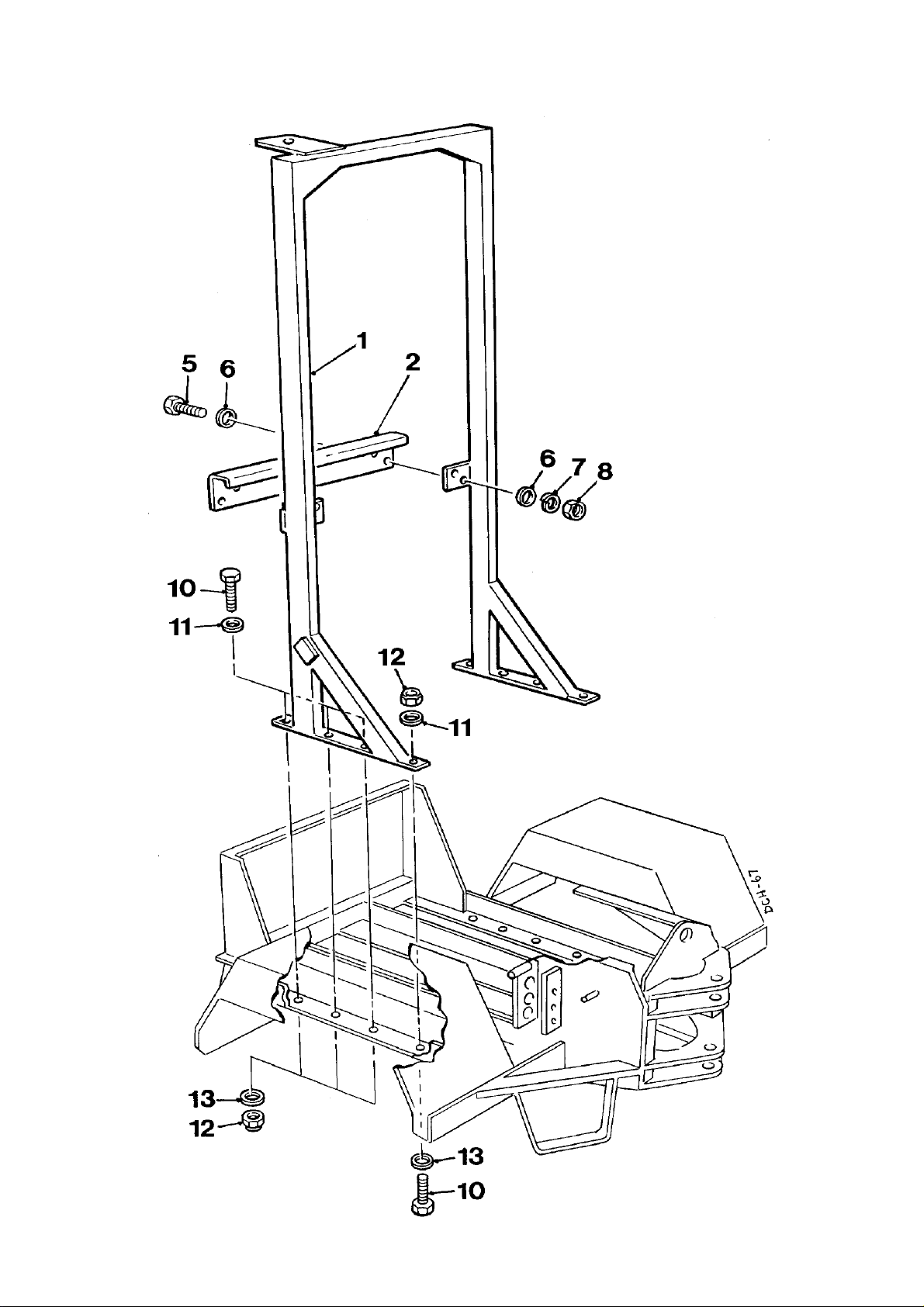
A - 10 4B2000 Dumper
DCH-67
Page 79

ROPS frame (Kit)
………
V2005013
(see page A - 11).
V602755
(see page E - 3A)
………
V2005013
(see page A - 11).
Item Part no Serial no Description Qty
A - 10
Machines with Lister-Petter TS2 & TR2 engines
V602753 ROPS KIT, includes items 1 to 15 listed below.
Plus……
Seat assembly KAB XH2/P2N to ISO 6683
TS/TR exhaust silencer kit
Machines with Lister-Petter PH2, P600 & ST2 engines
V602754 ROPS KIT, includes items 1 to 15 listed below.
Plus……
Seat assembly KAB XH2/P2N to ISO 6683
1 V2005004 May-99 / FRAME (ROPS) c/w stiffener, assy 1
2 V2005011 STIFFENER 1
3 V2004754
5 11S04C SCREW, set 4
6 267S06 WASHER, flat 8
7 17S05 WASHER, spring 4
8 7S04 NUT 4
10 11S13H SCREW, set 8
11 V2003892 WASHER, special 8
12 59S15 NUT, Nyloc 8
13 267S08 WASHER, flat 8
14 V2005030
15 101S05D
DECAL, damage (not illustrated)
PLATE, R.O.P.S. ident. (not illustrated)
RIVET, pop (not illustrated)
1
4
V601140 / issue 02 0800
Page 80
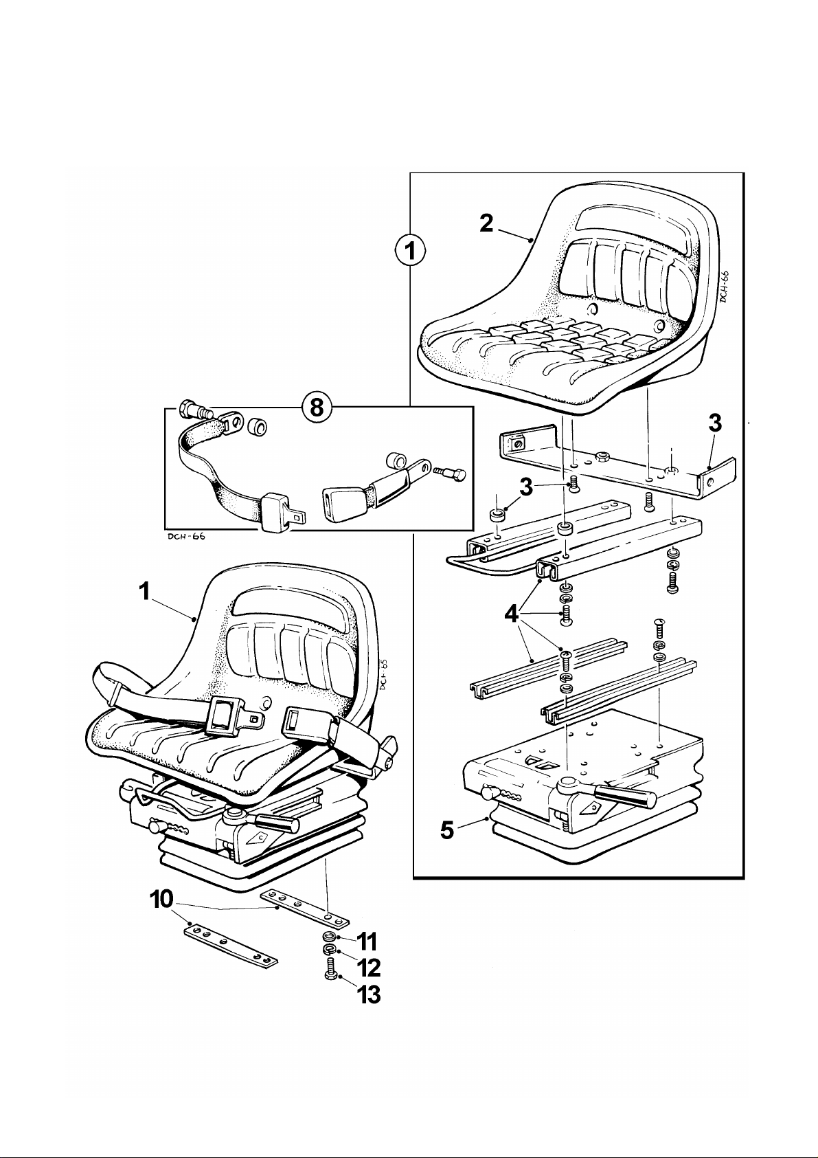
A - 11 4B2000 Dumper
Page 81

SEAT, assembly A - 11
KAB XH2/P2N' to ISO 6683
Item Part no Serial no Description Qty
This seat assembly is used with and is included with R.O.P.S. kits…..
V602753 (see page A - 10)
V602754 (see page A - 10)
V602755 (see page E - 3A)
All 4B2000 dumpers which are fitted with a R.O.P.S. (Roll Over Protective
Structure) including 'Export' models must be fitted with this seat assembly.
Earlier versions of the KAB seating XL or XH suspension unit do not
meet the requirements of the ISO 6683 (Seat Belt Pull Test) and should not
be used in conjunction with a R.O.P.S.
1 V2005013 May-99 / SEAT, assembly c/w with seat belt 1
2 V2000954 SEAT, 'KAB P2N'
3 V602750 BRACKET, anchorage 1
4 V602752 SLIDE RAIL, assembly 1
5 V602751 UNIT, suspension 'XH2' (ISO 6683) 1
8 V602749 BELT, seat 1
10 V2004206 PLATE, clamp 2
11 267S05 WASHER, flat 4
12 17S04 WASHER, spring 4
13 11S03C SCREW, set 4
V601140 / issue 02 0800
Page 82

Axles
WHEELS & TYRES B - 1
STEERING COLUMN B - 2
AXLES, Salisbury
Dry disc brakes B - 5
Non braked B - 6
Oil immersed brakes B - 7
AXLES, Newage
Axle identification: Up to serial no. 1092
Axle identification: From serial no. 1093
200RF with brakes: Up to serial no. 1092
175RF without brakes: Up to ser. no. 1092
212 without brakes: From serial no. 1093
Input Pinion & Differential B - 10
Planet Carrier & Axle Casing B - 10A
Hub & Axle Shaft B - 10B
215 with brakes: From serial no. 1093
Input Pinion & Differential B - 11
B - 7A
B - 7B
B - 8
B - 9
Planet Carrier & Axle Casing B - 11A
Hub & Axle Shaft B - 11B
Brakes B - 11C
Page 83
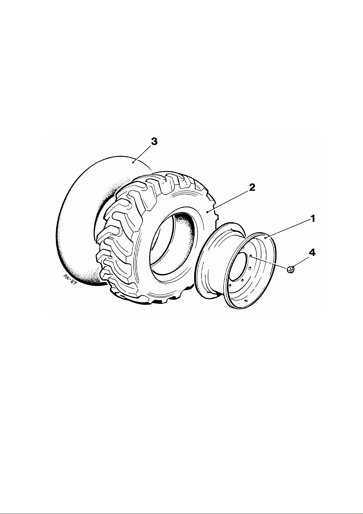
B - 1 4B2000 Dumper
AX-87
Page 84

WHEELS & TYRES B - 1
Item Part no Serial no Description Qty
Wheels suitable for all types of axle.
- 24S25 WHEEL ASSEMBLY, L.H. 2
- 24S26 WHEEL ASSEMBLY, R.H. 2
1 30192A03 RIM, 5.5 x 16 1
2 20S08 TYRE, 7.5 x 16 1
3 23S03 TUBE, 7.5 x 16 1
4 10668A01 NUT, wheel 20
Wheels suitable for all types of axle, except
for Salisbury dry disc and non braked.
- 24S29 WHEEL ASSEMBLY, L.H. 2
- 24S30 WHEEL ASSEMBLY, R.H. 2
1 20131A03 RIM, 7 x 15 1
2 20S17 TYRE, 10/75 x 15 1
3 23S11 TUBE, 10 x 15 1
4 10668A01 NUT, wheel 20
- 24S05 WHEEL ASSEMBLY, L.H. 2
- 24S06 WHEEL ASSEMBLY, R.H. 2
1 20131A02 RIM, 9 x 15 1
2 20S13 TYRE, 11.5/80 x 15 1
3 23S08 TUBE, 11.5 x 15 1
4 10668A01 NUT, wheel 20
V601140 / issue 02 0800
Page 85
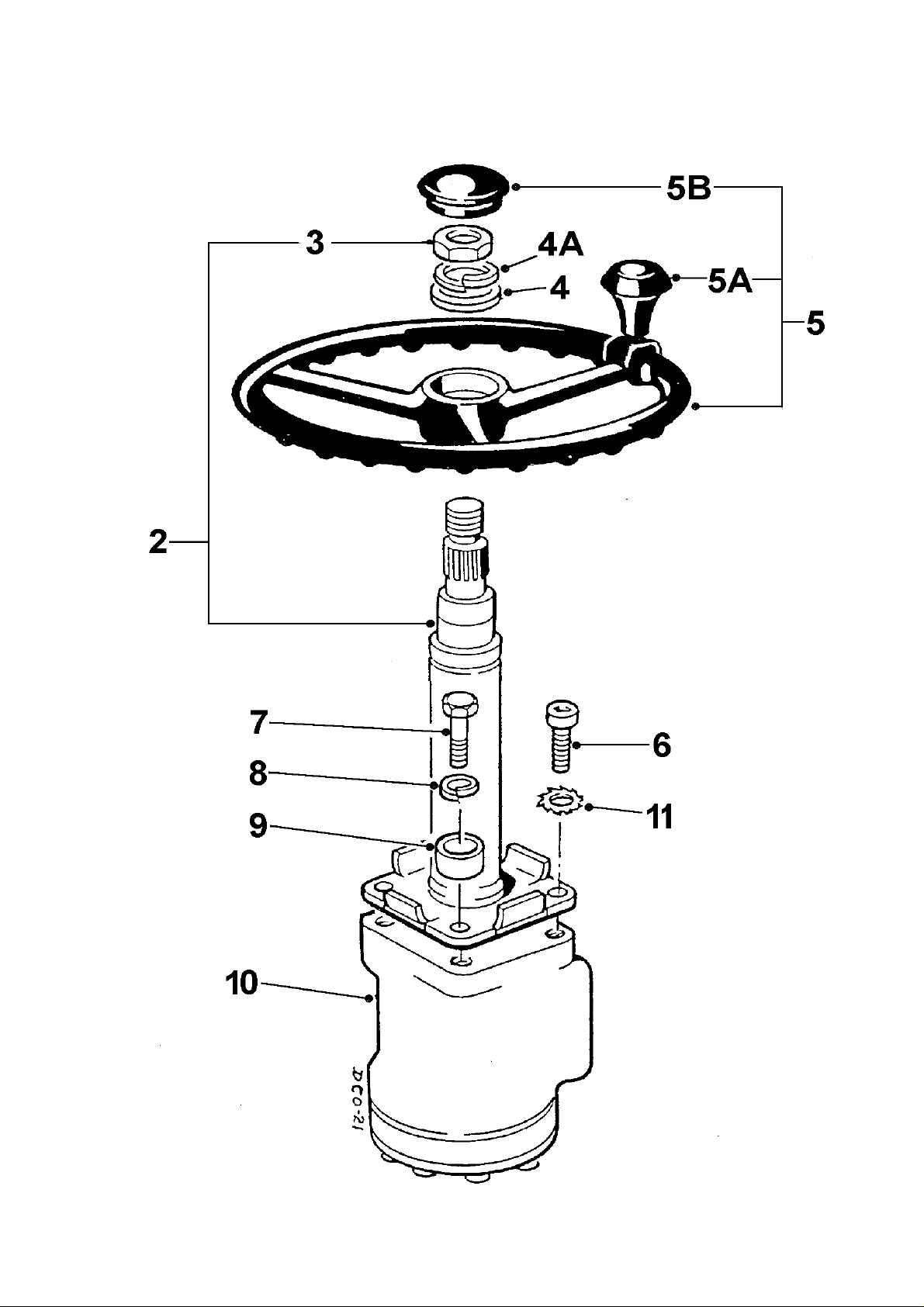
B - 2 4B2000 Dumper
Page 86

STEERING COLUMN B - 2
………….
……
…..
Item Part no Serial no Description Qty
2 CSE1781 COLUMN, steering assembly 1
3 95S06 #
3
4 267S09 WASHER, flat 1
4A 17S08 WASHER, spring 1
5 40064A01 WHEEL, steering, 400mm dia 1
(OBSOLETE: use V2002350)
5B 10314A01 CAP 1
5 V2002350 WHEEL, steering, 400mm dia 1
5B V601232 CAP 1
V601233 REDUCER, cap 1
NUT (5/8" UNF)
NUT (M16 x 1.5 pitch)
#
# Check thread before ordering nut
1
1
5 V2003164 WHEEL, steering, 350mm dia , c/w knob
(OBSOLETE: use V2004152) 1
5B V601232 CAP 1
5 V2004152 WHEEL, steering, 350mm dia 1
5A V600491 SPINNER, knob 1
5B V2004153 CAP 1
6 103S04B SCREW, socket 2
7 69S03G BOLT 2
8 41S05 WASHER, spring 2
9 CSE182 SPACER 2
10 CSE1782 UNIT, steering, EM&S 1
(No load sensing. Not used with hydraulic
rotating skips)
V602683 KIT, seals, EM&S AR
10 V2003312 UNIT, steering 1
(With load sensing. Used with hydraulic
rotating skips)
11 67S04 WASHER, shakeproof 2
V601140 / July '02
Page 87
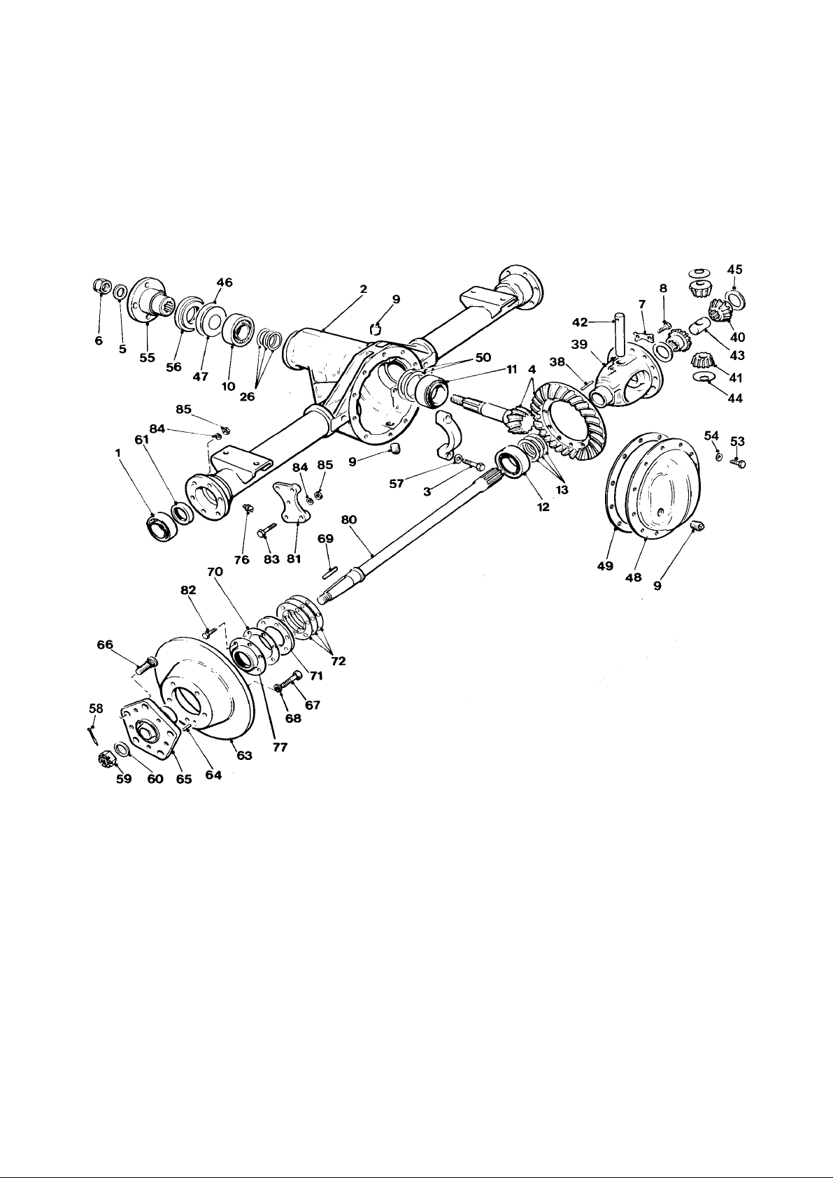
B - 5 4B2000 Dumper
Page 88

DRIVE AXLE, Salisbury dry disc B - 5
Item Part no Serial no Description Qty
- 30166A01 AXLE, assembly 1
1 30166A0101 BEARING 2
2 30166A0102 CARRIER & TUBE, assembly 1
3 30166A0103 BOLT, diff bearing cap 4
4 30166A0104 GEAR & PINION assembly 1
5 30166A0105 WASHER 1
6 30166A0106 NUT, pinion locking 1
7 30166A0107 NUT, drive gear locking 6
8 30166A0108 BOLT, drive gear 12
9 30166A0109 PLUG, level/filler 3
10 30166A0110 BEARING 1
11 30166A0111 BEARING 1
12 30166A0112 BEARING 2
13 30166A0113 SHIM, diff bearing, 0.028" AR
13 30166A0114 SHIM, diff bearing, 0.030" AR
13 30166A0115 SHIM, diff bearing, 0.031" AR
13 30166A0116 SHIM, diff bearing, 0.032" AR
13 30166A0117 SHIM, diff bearing, 0.033" AR
13 30166A0118 SHIM, diff bearing, 0.034" AR
13 30166A0119 SHIM, diff bearing, 0.035" AR
13 30166A0120 SHIM, diff bearing, 0.036" AR
13 30166A0121 SHIM, diff bearing, 0.037" AR
13 30166A0122 SHIM, diff bearing, 0.038" AR
13 30166A0123 SHIM, diff bearing, 0.039" AR
13 30166A0124 SHIM, diff bearing, 0.040" AR
13 30166A0125 SHIM, diff bearing, 0.045" AR
26 30166A0126 SHIM, outer pinion bearing, 0.030" AR
26 30166A0127 SHIM, outer pinion bearing, 0.031" AR
26 30166A0128 SHIM, outer pinion bearing, 0.032" AR
26 30166A0129 SHIM, outer pinion bearing, 0.033" AR
26 30166A0130 SHIM, outer pinion bearing, 0.034" AR
26 30166A0131 SHIM, outer pinion bearing, 0.035" AR
26 30166A0132 SHIM, outer pinion bearing, 0.036" AR
26 30166A0133 SHIM, outer pinion bearing, 0.037" AR
26 30166A0134 SHIM, outer pinion bearing, 0.038" AR
26 30166A0135 SHIM, outer pinion bearing, 0.039" AR
26 30166A0136 SHIM, outer pinion bearing, 0.040" AR
- 30166A0137 DIFFERENTIAL CASE, assembly 1
38 30166A0138 PIN, roll 1
39 30166A0139 CASE, differential 1
40 30166A0140 GEAR, side, diff 2
41 30166A0141 MATE, diff pinion 2
42 30166A0142 SHAFT, diff pinion mate 1
43 30166A0143 SPACER, axle shaft 1
44 30166A0144 WASHER, thrust 2
V601140 / issue 01 0891 continued >
Page 89
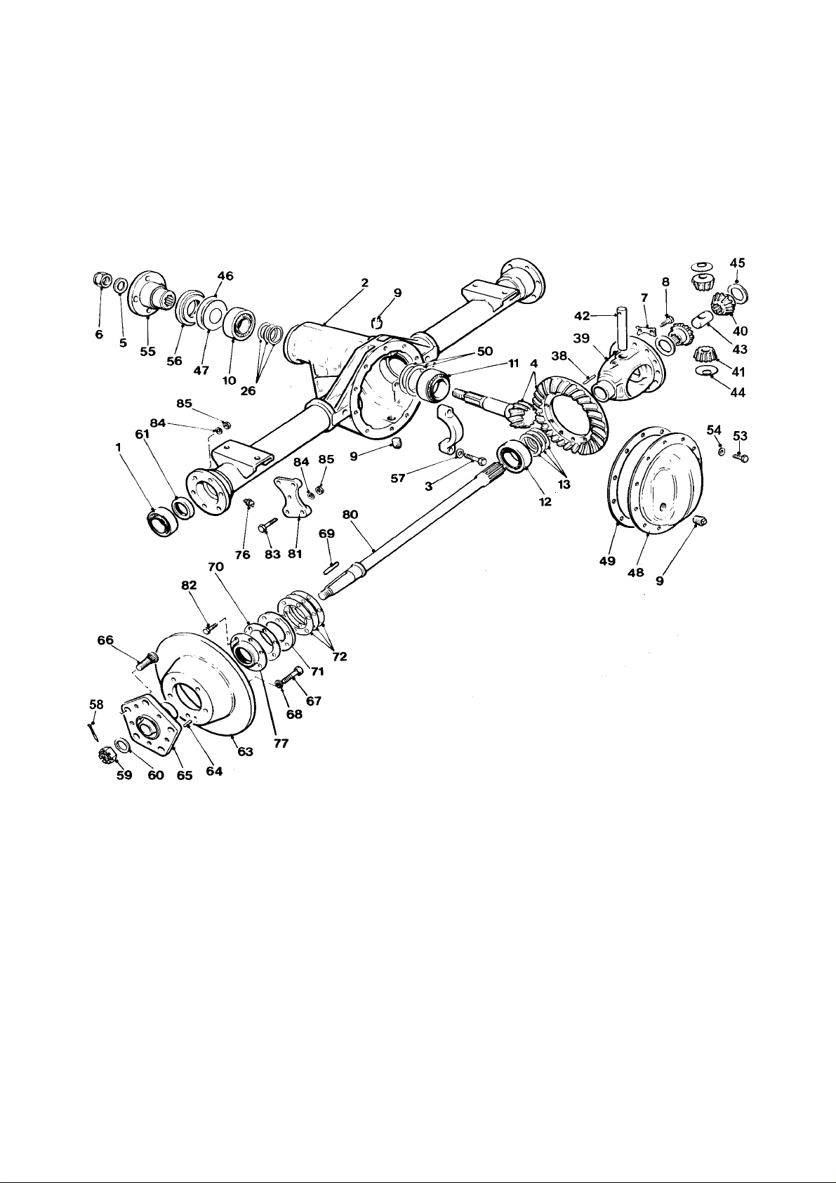
B - 5 4B2000 Dumper
Page 90

DRIVE AXLE, Salisbury dry disc B - 5
Item Part no Serial no Description Qty
45 30166A0145 WASHER, thrust 2
46 30166A0146 GASKET, pinion oil seal 1
47 30166A0147 SLINGER, pinion oil 1
48 30166A0148 COVER, gear carrier 1
49 30166A0149 COVER, gasket 1
50 30166A0150 SHIM, inner pinion bearing, 0.003" AR
50 30166A0151 SHIM, inner pinion bearing, 0.005" AR
50 30166A0152 SHIM, inner pinion bearing, 0.010" AR
53 30166A0153 BOLT, carrier cover 10
54 30166A0154 WASHER, locking 10
55 30166A0155 FLANGE, companion 1
56 30166A0156 SEAL, oil, pinion 1
57 30166A0157 WASHER, locking, diff bearing cap 4
58 30166A0158 PIN, cotter 2
59 30166A0159 NUT, shaft 2
60 30166A0160 WASHER, shaft 2
61 30166A0161 SEAL, oil, axle shaft 2
- 30166A0162 BRAKE, hub & disc assembly 2
63 30166A0163 DISC, brake 2
64 30166A0164 PIN, roll 4
65 30166A0165 HUB & STUD, assembly 1
66 30166A0166 STUD, wheel 10
67 30166A0167 BOLT, brake disc 10
68 30166A0154 WASHER, locking 10
69 30166A0169 KEY, axle shaft 2
70 30166A0170 GASKET, hub oil seal 2
71 30166A0171 PLATE, RETAINER 2
72 30166A0172 SHIM, wheel bearing, 0.003" AR
72 30166A0173 SHIM, wheel bearing, 0.005" AR
72 30166A0174 SHIM, wheel bearing, 0.010" AR
72 30166A0175 SHIM, wheel bearing, 0.030" AR
76 30166A0176 NIPPLE, grease 2
77 30166A0177 SEAL, oil, hub, assembly 2
77 30166A0178 CONTAINER, oil seal 1
77 30166A0179 SEAL, oil 1
80 30166A0180 SHAFT, axle 2
81 30166A0181 BRACKET, caliper 2
82 30166A0182 BOLT, brake back plate 6
83 30166A0183 BOLT, caliper mounting plate 6
84 30166A0154 WASHER, locking 12
85 30166A0185 NUT, brake back plate 12
- 6S05C Axle fixings BOLT 4
- 132S05 (not illustrated) NUT 4
- 10S04 WASHER 4
V601140 / issue 01 0891
Page 91
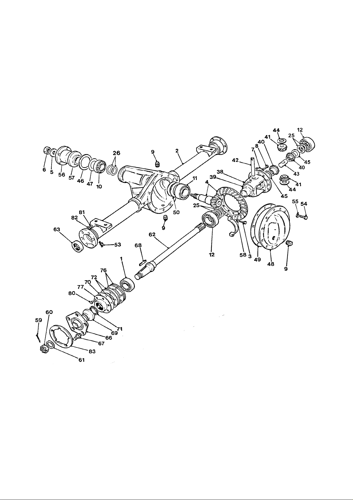
B - 6 4B2000 Dumper
Page 92

DRIVE AXLE, Salisbury non braked B - 6
Item Part no Serial no Description Qty
- 30171A01 AXLE, assembly 1
1 30166A0101 BEARING 2
2 30171A0101 CARRIER & TUBE, assembly 1
3 30166A0103 BOLT, diff bearing cap 4
4 30166A0104 GEAR, assembly 1
5 30166A0105 WASHER 1
6 30166A0106 NUT, pinion locking 1
7 30166A0107 STRAP, ‘L’, drive gear 6
8 30166A0108 BOLT, drive gear 12
9 30166A0109 PLUG, level/filler 3
10 30166A0110 BEARING 1
11 30166A0111 BEARING 1
12 30166A0112 BEARING 2
25 30166A0113 SHIM, diff bearing, 0.028" AR
25 30166A0114 SHIM, diff bearing, 0.030" AR
25 30166A0115 SHIM, diff bearing, 0.031" AR
25 30166A0116 SHIM, diff bearing, 0.032" AR
25 30166A0117 SHIM, diff bearing, 0.033" AR
25 30166A0118 SHIM, diff bearing, 0.034" AR
25 30166A0119 SHIM, diff bearing, 0.035" AR
25 30166A0120 SHIM, diff bearing, 0.036" AR
25 30166A0121 SHIM, diff bearing, 0.037" AR
25 30166A0122 SHIM, diff bearing, 0.038" AR
25 30166A0123 SHIM, diff bearing, 0.039" AR
25 30166A0124 SHIM, diff bearing, 0.040" AR
25 30166A0125 SHIM, diff bearing, 0.045" AR
26 30166A0126 SHIM, outer pinion bearing, 0.030" AR
26 30166A0127 SHIM, outer pinion bearing, 0.031" AR
26 30166A0128 SHIM, outer pinion bearing, 0.032" AR
26 30166A0129 SHIM, outer pinion bearing, 0.033" AR
26 30166A0130 SHIM, outer pinion bearing, 0.034" AR
26 30166A0131 SHIM, outer pinion bearing, 0.035" AR
26 30166A0132 SHIM, outer pinion bearing, 0.036" AR
26 30166A0133 SHIM, outer pinion bearing, 0.037" AR
26 30166A0134 SHIM, outer pinion bearing, 0.038" AR
26 30166A0135 SHIM, outer pinion bearing, 0.039" AR
26 30166A0136 SHIM, outer pinion bearing, 0.040" AR
- 30166A0137 DIFFERENTIAL CASE, assembly 1
38 30166A0138 PIN, roll 1
39 30166A0139 CASE, differential 1
40 30166A0140 GEAR, side, diff 2
41 30166A0141 MATE, diff pinion 2
42 30166A0142 SHAFT, diff pinion mate 1
43 30166A0143 SPACER, axle shaft 1
V601140 / issue 01 0891 continued >
Page 93
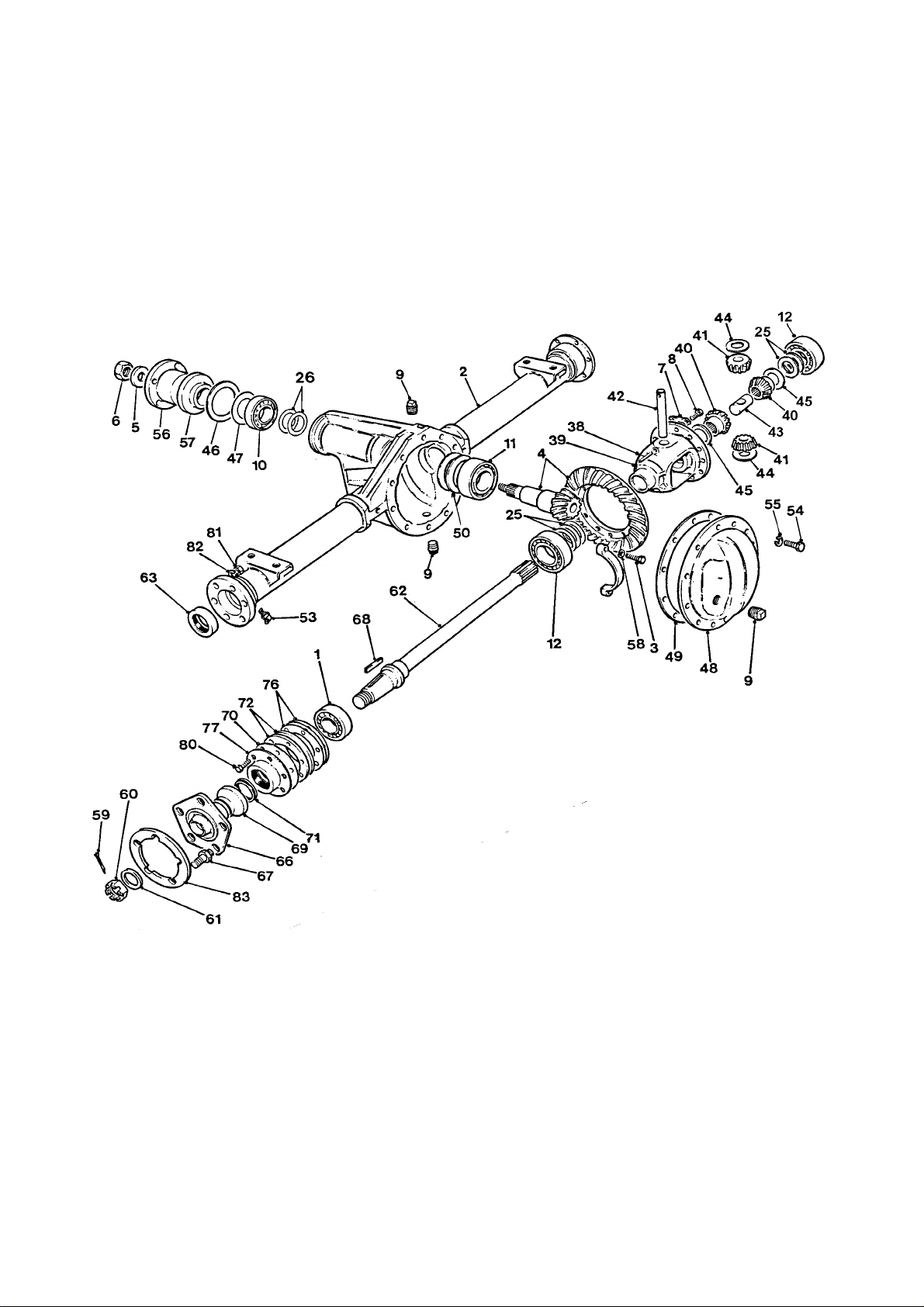
B - 6 4B2000 Dumper
Page 94

DRIVE AXLE, Salisbury non braked B - 6
Item Part no Serial no Description Qty
44 30166A0144 WASHER, thrust 2
45 30166A0145 WASHER, thrust 2
46 30166A0146 GASKET, pinion oil seal 1
47 30166A0147 SLINGER, pinion oil 1
48 30166A0148 COVER, gear carrier 1
49 30166A0149 COVER, gasket 1
50 30166A0150 SHIM, inner pinion bearing, 0.003" AR
50 30166A0151 SHIM, inner pinion bearing, 0.005" AR
50 30166A0152 SHIM, inner pinion bearing, 0.010" AR
53 30166A0176 NIPPLE, grease 2
54 30166A0153 BOLT, carrier cover 10
55 30166A0154 WASHER, locking 10
56 30166A0155 FLANGE, companion 1
57 30166A0156 SEAL, oil, pinion 1
58 30166A0157 WASHER, locking, diff bearing cap 4
59 30166A0158 PIN, cotter 2
60 30166A0159 NUT, shaft 2
61 30166A0160 WASHER, shaft 2
62 30166A0180 SHAFT, axle 2
63 30166A0161 SEAL, oil, axle shaft 2
- 30171A0102 WHEEL HUB, assembly 2
66 30171A0104 HUB, wheel 1
67 30171A0103 DOWEL, stud locking 5
67 30171A0105 STUD, wheel 10
68 30166A0169 KEY, axle shaft 2
69 30171A0106 HOUSING, ‘V’ ring 2
70 30166A0170 GASKET, hub oil seal 2
71 30171A0107 SEAL, ‘V’ ring 2
72 30171A0108 PLATE, retainer 4
76 30166A0172 SHIM, wheel bearing, 0.003" AR
76 30166A0173 SHIM, wheel bearing, 0.005" AR
76 30166A0174 SHIM, wheel bearing, 0.010" AR
76 30166A0175 SHIM, wheel bearing, 0.030" AR
77 30166A0177 SEAL, oil, hub, assembly 2
78 30166A0178 CONTAINER, oil seal 1
79 30166A0179 SEAL, oil 1
80 30166A0167 BOLT 12
81 30171A0109 NUT, locking 12
82 30171A0110 WASHER 12
83 ASE127 SPACER 2
- 6S05C Axle fixings BOLT 4
- 132S05 (not illustrated) NUT 4
- 10S04 WASHER 4
V601140 / issue 01 0891
Page 95
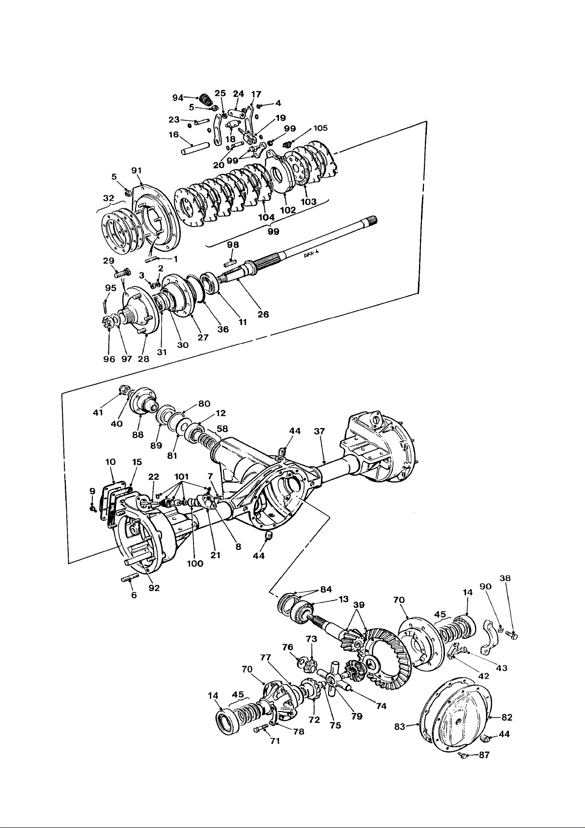
B - 7 4B2000 Dumper
Page 96

DRIVE AXLE, Salisbury oil immersed B - 7
Item Part no Serial no Description Qty
- 30242A01 AXLE, assembly 1
1 30242A0101 STUD, nylon patch locking 16
2 30242A0102 WASHER, locking 16
3 30242A0103 NUT 16
4 30242A0104 CIRCLIP 12
5 30242A0105 WASHER, locking 18
6 30242A0106 STUD 16
7 30242A0107 BOLT 4
8 30242A0108 WASHER, locking 4
9 30242A0109 SCREW & WASHER 16
10 30242A0110 COVER, brake link access 2
11 30242A0111 BEARING 2
12 30166A0110 BEARING 1
13 30166A0111 BEARING 1
14 30166A0112 BEARING 2
15 30242A0112 GASKET, brake housing cover 2
16 30242A0113 PIN, brake 2
17 30242A0114 LEVER, brake operating 4
18 30242A0115 PIN 2
19 30242A0116 CLEVIS 2
20 30242A0117 PIN, clevis 2
21 30242A0118 SLAVE CYLINDER, assembly 2
22 30242A0119 ROD, push 1
23 30242A0120 PIN 2
24 30242A0121 SLEEVE, push rod 2
25 30242A0122 SPACER, pivot 4
26 30242A0123 SHAFT, axle 2
27 30242A0124 HOUSING, bearing 2
28 30242A0125 HUB & STUD, assembly 2
29 30166A0166 STUD, wheel 5
30 30242A0127 SEAL, oil, rubber 2
31 30242A0153 SEAL, oil, leather 2
32 30242A0128 SHIM, wheel bearing, 0.08mm 2
32 30242A0129 SHIM, wheel bearing, 0.125mm 2
32 30242A0130 SHIM, wheel bearing, 0.25mm 2
32 30242A0131 SHIM, wheel bearing, 0.8mm 2
32 30242A0149 SHIM SPACER, 2.5mm 2
36 30242A0132 SEAL, ‘O’ ring 2
37 30242A0133 CARRIER & TUBE, brake housing 1
38 30166A0103 BOLT, diff bearing cap 4
V601140 / issue 01 0891 continued >
Page 97
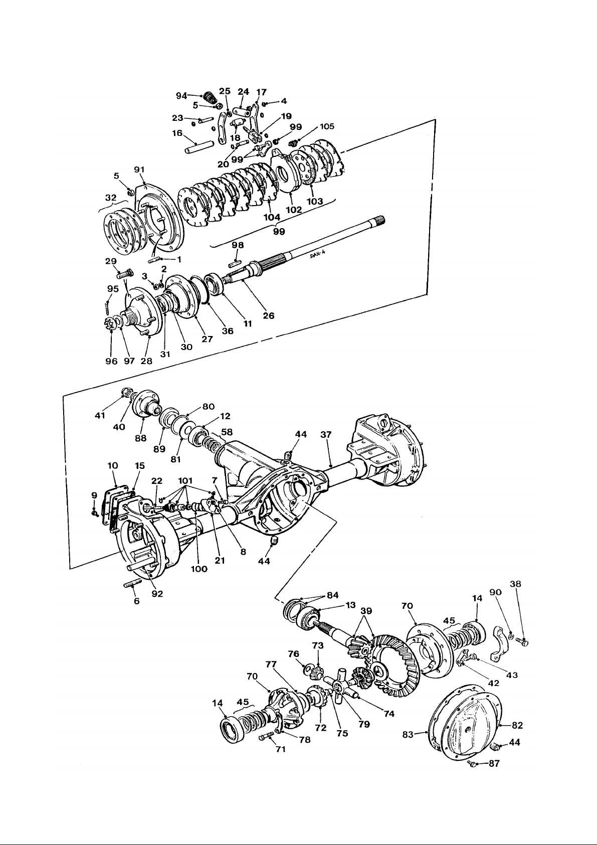
B - 7 4B2000 Dumper
Page 98

DRIVE AXLE, Salisbury oil immersed B - 7
Item Part no Serial no Description Qty
39 30166A0104 GEAR, assembly 1
40 30166A0105 WASHER 1
41 30166A0106 NUT, pinion locking 1
42 30166A0107 STRAP, ‘L’, drive gear 6
43 30166A0108 BOLT, drive gear 12
44 30166A0109 PLUG, level/filler 3
45 30166A0113 SHIM, diff bearing, 0.028" AR
45 30166A0114 SHIM, diff bearing, 0.030" AR
45 30166A0115 SHIM, diff bearing, 0.031" AR
45 30166A0116 SHIM, diff bearing, 0.032" AR
45 30166A0117 SHIM, diff bearing, 0.033" AR
45 30166A0118 SHIM, diff bearing, 0.034" AR
45 30166A0119 SHIM, diff bearing, 0.035" AR
45 30166A0120 SHIM, diff bearing, 0.036" AR
45 30166A0121 SHIM, diff bearing, 0.037" AR
45 30166A0122 SHIM, diff bearing, 0.038" AR
45 30166A0123 SHIM, diff bearing, 0.039" AR
45 30166A0124 SHIM, diff bearing, 0.040" AR
45 30166A0125 SHIM, diff bearing, 0.045" AR
58 30166A0126 SHIM, outer pinion bearing, 0.030" AR
58 30166A0127 SHIM, outer pinion bearing, 0.031" AR
58 30166A0128 SHIM, outer pinion bearing, 0.032" AR
58 30166A0129 SHIM, outer pinion bearing, 0.033" AR
58 30166A0130 SHIM, outer pinion bearing, 0.034" AR
58 30166A0131 SHIM, outer pinion bearing, 0.035" AR
58 30166A0132 SHIM, outer pinion bearing, 0.036" AR
58 30166A0133 SHIM, outer pinion bearing, 0.037" AR
58 30166A0134 SHIM, outer pinion bearing, 0.038" AR
58 30166A0135 SHIM, outer pinion bearing, 0.039" AR
58 30166A0136 SHIM, outer pinion bearing, 0.040" AR
- 30242A0134 DIFFERENTIAL CASE, assembly 1
70 30242A0135 CASE, diff 1
71 30242A0136 BOLT, diff case 8
72 30242A0137 GEAR, side 2
73 30242A0138 PINION, mete 4
74 30242A0139 CROSS SHAFT, pinion mate 1
75 30242A0140 SPACER, split, axle shaft 2
76 30242A0141 WASHER, thrust, diff pinion mate 4
77 30242A0142 WASHER, thrust, diff side gear 2
78 30242A0143 STRAP, locking, diff case 4
79 30242A0144 PIN, roll 1
V601140 / issue 01 0891 continued >
Page 99
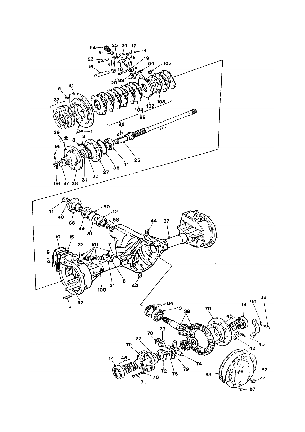
B - 7 4B2000 Dumper
Page 100

DRIVE AXLE, Salisbury oil immersed B - 7
Item Part no Serial no Description Qty
80 30166A0146 GASKET, pinion oil seal 1
81 30166A0147 SLINGER, oil, pinion 1
82 30242A0145 COVER, gear carrier 1
83 30166A0149 GASKET, carrier cover 1
84 30166A0150 SHIM, pinion bearing inner, 0.003" AR
84 30166A0151 SHIM, pinion bearing inner, 0.005" AR
84 30166A0152 SHIM, pinion bearing inner, 0.010" AR
87 30242A0146 BOLT & WASHER 10
88 30166A0155 FLANGE, companion 1
89 30166A0156 SEAL, oil, pinion 1
90 30166A0157 WASHER, locking, diff bearing cap 4
91 30242A0147 COVER, brake & spindle housing 2
92 30242A0148 PIN, anchor, brake 2
94 30242A0150 SPRING, return, conical 2
95 30166A0158 PIN, cotter 2
96 30166A0159 NUT, shaft 2
97 30166A0160 WASHER, shaft 2
98 30166A0169 KEY 2
99 30242A0152 BRAKE & DISC, assembly, 8 plate
(includes items 102, 103, 104) 2
100 30242A0154 SEAL, ‘O’ ring 2
101 30242A0155 KIT, seal, slave cylinder 2
102 30242A0156 ACTUATOR 2
103 30242A0157 PLATE, brake, middle 16
104 30242A0158 PLATE, brake, intermediate 16
105 30242A0159 SPRING 2
Axle fixings (not illustrated)
- 6S05E BOLT 8
- 132S05 NUT 8
- 10S04 WASHER 8
V601140 / issue 01 0891
 Loading...