

Page 1
Operation Manual
“Marine”
Vessel:
Type:
Engine No.:
Document ID: DBAC753771
Winterthur Gas & Diesel Ltd. 24hrs Support:
Schützenstrasse 1−3 Wärtsilä Services Switzerland Ltd.
CH-8400 Winterthur Zürcherstrasse 12
Switzerland CH 8400 Winterthur
Switzerland
+41 52 262 80 10
[email protected]
Page 2

E 2017-08 Winterthur Gas & Diesel Ltd., Printed in Switzerland – All rights reserved
No part of this publication may be reproduced or copied in any form or by any means
(electronic, mechanical, graphic, photocopying, recording, taping or other information retrieval
systems) without the prior written permission of the copyright holder.
Winterthur Gas & Diesel Ltd. makes no representation, warranty (express or implied) in this
publication and assumes no responsibility for the correctness, errors or omissions of information contained herein. Information in this publication is subject to change without notice.
NO LIABILITY, WHETHER DIRECT, INDIRECT, SPECIAL, INCIDENTAL OR CONSEQUENTIAL, IS ASSUMED WITH RESPECT TO THE INFORMATION CONTAINED HEREIN. THIS
PUBLICATION IS INTENDED FOR INFORMATION PURPOSES ONLY.
Page 3

Operation Manual
“Marine”
Vessel:
Type:
Engine No.:
Document ID: DBAC753771
Winterthur Gas & Diesel Ltd. 24hrs Support:
Schützenstrasse 1−3 Wärtsilä Services Switzerland Ltd.
CH-8400 Winterthur Zürcherstrasse 12
Switzerland CH 8400 Winterthur
Switzerland
+41 52 262 80 10
[email protected]
Page 4

E 2017-04 Winterthur Gas & Diesel Ltd., Printed in Switzerland – All rights reserved
No part of this publication may be reproduced or copied in any form or by any means (electronic, mechanical, graphic, photocopying, recording, taping or other information retrieval systems)
without the prior written permission of the copyright holder.
Winterthur Gas & Diesel Ltd. or Wärtsilä Services Switzerland Ltd. make no representation,
warranty (express or implied) in this publication and assumes no responsibility for the correctness, errors or omissions for information contained herein. Information in this publication is
subject to change without notice.
NO LIABILITY WHETHER DIRECT, INDIRECT, SPECIAL, INCIDENTAL OR CONSEQUENTIAL, IS ASSUMED WITH RESPECT TO THE INFORMATION CONTAINED HEREIN. THIS
PUBLICATION IS CONFIDENTIAL AND INTENDED FOR INFORMATION PURPOSES ONLY.
Page 5
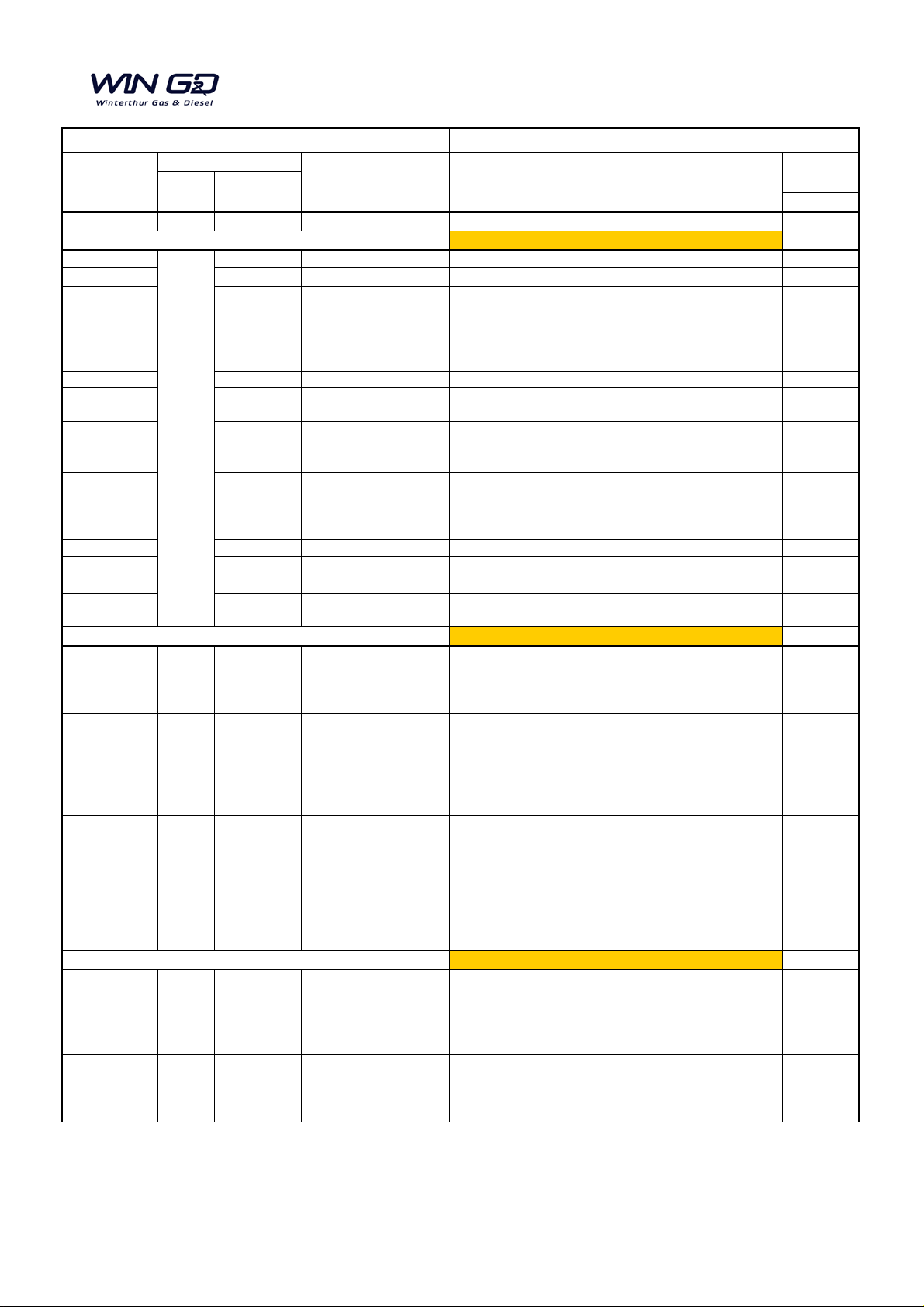
Summary for Operation Manual (OM)
Page No. Title Subject
Date No.
new
exch.
2014 Operation Manual, Issue 2014
x
Date of publication 2014-08-19
0020-1/A1 TOC New chapter 9314-2/A1 added x
0030-1/A1 Subject Index New chapter 9314-2/A1 added x
0080-1/A1 Basic Engine Data Additional illustrat i ons added; x
0590-1/A1
Operation during Unusual
Conditions - Defective
Additional data for three turboc harger c onfiguration and
x
0710-1/A1 Diesel Engine Fuels Latest data, minor t ext c hanges x
4104-1/A1 Supply Drive Unit
Additional illustrat i on f or 9-cylinder engines added;
x
7218-1/A1 Cylinder Lubrication
page 2: Illustration schematic diagram f or 9-cylinder
x
8016-1/A2
Lubricating Oil System - 9-
page 4: New illustration added
x
Group 9 Group TOC New chapter 9314-2/A1 added x
9314-1/A1
Oil Mist Detector -
Schematic diagram updated; terminology updated x
9314-2/A1
Oil Mist Detector -
New chapter for 9-cylinder engines added x
Date of publication 2014-09-16
OM_2015-05 2015-05
Cover page, Disclaimer
Data about Wintert hur Gas & Diesel (Wi nGD) and Wärtsilä
x
8019-1/A1 2015-05
Fuel System - 6-cylinders
Fig. 5: Illustrati on updated;
x
8019-1/A2 2015-05 Fuel System - 9-cylinders
Fig. 5: Illustrati on updated;
x
Date of publication 2015-06-09
0210-1/A1 2015-07
Safety Precautions and
paragraph 2: Warning about oil mist detector added;
x
0270-1/A1 2015-07
Service
Changing Over from
Temperature gradient changed from 15°C/min to 2°C/min
x
2014-09
Manual
Page or
Modification Service
Engine Documentation
Modification
W-X82
Turbocharger
Table 1 added
illustrations updated
engines added
page 13, 14: pressure transmi tter PT3139C added
cylinders
6-cylinder to 8-cylinder
9-cylinder
and all related pages
to 8-cylinders
page 5: Key to Fig. 1 updated
page 8: New illustration added
page 9: New illustration added; Key to Fig. 3 updated
Services Switzerland (W SCH) added;
New Layout WinGD;
Disclaimer updated (WinGD and WS CH added);
para 4.3 and 4.4: reference changed;
para 4.4: procedure changed; alternative proc edure added;
para 4.5: procedure changed; data about spare part kit
added;
para 4.3 and 4.4: reference changed;
para 4.4: procedure changed; alternative proc edure added;
para 4.5: procedure changed; data about spare part kit
added;
all paragraphs: minor text changes and updates (e.g.
position numbers);
Warnings (General Data)
Bulletin RT-82
Diesel Oil to Heavy Fuel
Oil and Vice Versa
paragraph 8: Warning about hot part s added;
paragraph 9: Warning about injury hazards added;
paragraph 13: Warning about air run added;
related to the Service Bullet i n;
1/4 16/10/2017
Page 6

Summary for Operation Manual (OM)
Page No. Title Subject
Date No.
new
exch.
Manual
Page or
Modification Service
Engine Documentation
Modification
W-X82
0710-1/A1 2015-07
EAAD085468
Service
Diesel Engine Fuels
Latest data from fuel specification added;
Note 2) to Fig. 1: min. val ue f or fuel viscosity changed from
x
0720-1/A1
2015-07
EAAD085468
Operating Media - Fuel
Fig. 1: Schemati c Diagram - Fuel System updated;
x
0750-1/A1 2015-07
Service
Operating Media
paragraph 2.1: additional data added
x
4003-2/A1 2015-07 EAAD085118 Engine Control Diagram
Document updated with latest data:
-At servo oil rail new group with PT2041A, PI2041L, 8.11-1,
x
4003-2/A2 2015-07 EAAD085118 Engine Control Diagram
Document updated with latest data:
-At servo oil rail new group with PT2041A, PI2041L, 8.11-1,
x
Bulletin
RT-126
Table 1: maximum s ul f ur val ue changed from 4.5 to 3.5
m/m[%];
Fig. 1: Viscosi t y/ T emperature Diagram updated;
13 cSt to 10 cSt;
Table 2: Pour point (upper) winter max. value changed
from 0 to -6; Carbon residue m ax. value removed;
minor changes in the text;
Data about Wärtsi l ä Service Switzerland Ltd and Wi nGD
added;
EAAD085894
Bulletins
RT-138
(Version 4)
RT-138_1
(Version 4)
RT-161
Treatment and Fuel
System
Key to Fig. 1: Item s 31, 32, 33 added;
para 3: minor text changes;
para 4: text changed; data about additional leakage
collection tank added;
Structure of the document changed;
Table 1: data FZG gear machine test added
Table 2: data FZG gear machine test added
paragraph 2.4: Sample point added
paragraph 3.1: updated
Fig. 1: illustrati on updat ed
paragraph 3.2: new data and Fig. 2 added
paragraph 3.3: new paragraph added
paragraph 3.4: new paragraph added
paragraph 7: new paragraph added
paragraph 8.1: new paragraph added
paragraph 8.2: list of approved lubricat i ng oi l s updated
paragraph 8.3: new table added added
Chapter updated (latest data from Revision 4 of the
Service Bulletin RT-138);
Fig. 1 and Fig. 2: new illustrati on with l atest data;
Table 4: List of Validat ed Lubri cating Oils updated (latest
data from January 2015);
Table 5: List of Validat ed System Oils updated (latest data
from January 2015);
4.23 and accumulator added;
-Check point 3.17 top of ICU removed.
4.23 and accumulator added and connection L2 with
T2042A, PI2042L, 8.11-2 removed;
P
-At cylinder lubrication c onnection L2 remov
onnected the two servo oil pipes to one pipe.
c
2/4 16/10/2017
ed and
Page 7
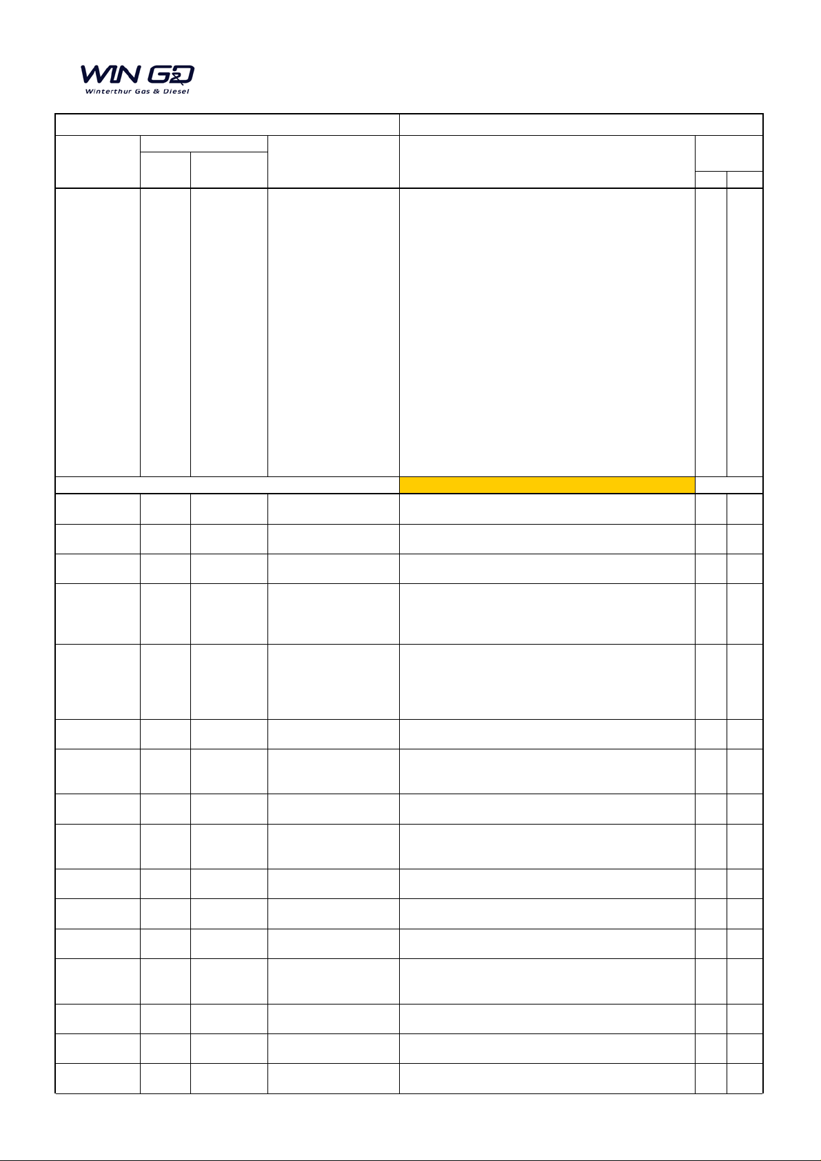
Summary for Operation Manual (OM)
Page No. Title Subject
Date No.
new
exch.
Manual
Page or
Modification Service
Engine Documentation
Modification
W-X82
4003-3/A1 2015-01 EAAD085118
Control and Auxiliary
Systems
Document updated with latest data:
x
Date of publication 2015-07-28
0050-1/A1 2017-08
Update
WinGD
Short Description of the
Engine
Minor text changes x
0120-1/A1 2017-08
Update
Prepare the Fuel System
Correction of References to Fi g 1; Chapter 3.2 Leak Test
x
0120-1/A2 2017-08
Update
Prepare the Fuel System
Correction of References to Fi g 1; Chapter 3.2 Leak Test
x
0250-1/A1 2017-04
Update
Operating Data Sheet
Torisional vibration damper (damper inlet):
x
0250-2/A1 2017-04
Update
Operating Data Sheet
PT2711A: ALM value changed from 1. 5 bar to 2.2 bar;
x
0270-1/A1 2017-08
Update
WinGD
Change-over from HFO
to MDO and back
Changed description and changed procedure x
0410-1/A1 2017-08
Update
Running in of New
Changed procedure for running-in x
0710-1/A1 2017-08
Update
Diesel Engine Fuels Text changed for Fuel additives x
0750-1/A1 2017-08
Update
Lubricating Oil
Update according to Service Bull etin (Text changes,
Particle Count; new Tables 4 and 5, updated F i gures 1 and
x
1203-1/A1 2017-08
Update
WinGD
Thrust Bearing Minor text changes, Section 1.1 deleted x
2722-1/A1 2017-08 EAAD086283 Injection Valve Updated section drawing x
3326-1/A1 2017-08 EAAD086618
Crosshead and Guide
Shoe
Text changed; Fig. 1 updated with shorter Guide rail s x
4003-1/A1 2017-08
Update
Engine Control
Table 4: Text changed; Table 5: Note deleted; Para 4.7:
x
4325-1/A1 2017-08
Update
Starting Air Shut-off
Steps 2 to 6 deleted x
5556-2/A1 2017-08
Update
Fuel Pump - Cutting Out
Procedures updated (2.1: step 10 and step 12 to 16; 2.2:
x
5583-1/A1 2017-08
Update
WinGD
Fuel Pump Actuator Update drawing x
-Page 11: PT2041A, PI2041L, 8. 11-1 have been removed.
Address 313 has been changed to 314;
-Page 12: PT2041A, PI2041L, 8. 11-1, PT2042A, PI2042L,
8.11-2 and connection 319 have been removed. Addres s
313 has been changed to 314. Only one servo oil pipe;
-Page 13: All signals relat ed to the turbocharger updated;
-Page 14: All signals relat ed to the turbocharger updated;
-Page 15,16: New group with PT2041A, PI2041L, 8.11-1,
4.23 added;
-Page 17,18: New group with PT2041A, PI2041L, 8.11-1,
4.23 added. Connection 319 has been removed;
-Page 19,20: Check point 3.17 t op of ICU has
r
emoved;
-Page 22: Oil mist detection MK6 has been replaced by
MK7.
been
WinGD
WinGD
WinGD
WinGD
WinGD
WinGD
WinGD
for Operation
for Operation
Pressure and
Temperature Ranges
Alarms and Safeguards
Cylinder Liners and
Piston Rings
deleted
deleted
Min. pressure value changed from 1.0 bar to
2.8 bar; max. pressure 5.0 bar (value added);
Note added;
Medium name changed to 'Tors i onal vibration damper oil
(steel spring damper)';
Note 5 changed
2, updated Tables 6 and 7)
WinGD
WinGD
WinGD
Valve
and Cutting In
step 2 deleted; Para 4.11: s t ep 2 changed, step 3 added;
Para 4.12.1: step 4 changed
step 6 to 10)
3/4 16/10/2017
Page 8
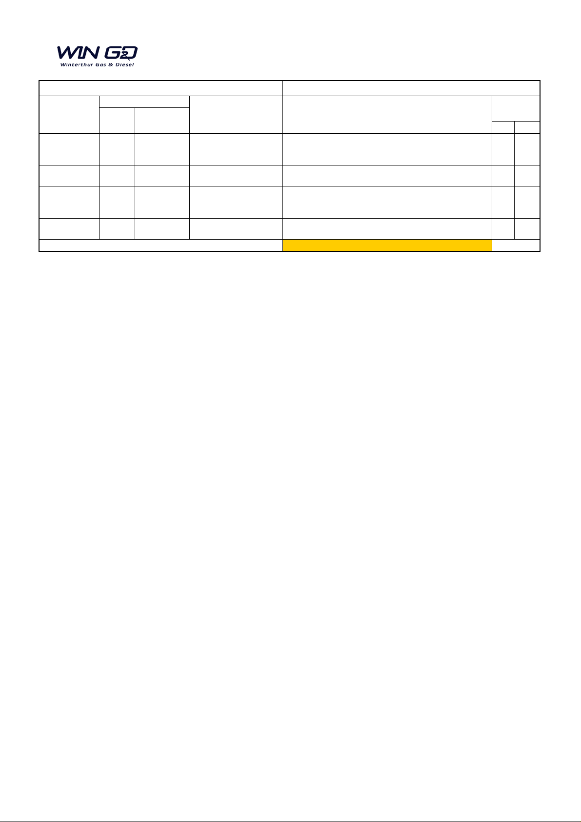
Summary for Operation Manual (OM)
Page No. Title Subject
Date No.
new
exch.
Manual
Page or
Modification Service
Engine Documentation
Modification
W-X82
6510-1/A1 2017-08
Update
WinGD
Cleaning the
Minor text changes (only cleaning of com pressor) x
6606-1/A1 2017-08
Update
WinGD
Operating Instructions
and Cleaning
Fig. 1 FW line changed x
6735-1/A1 2017-08
Update
Scavenge Air Was te
Text corrections: First paragraph -5° C replaced with related
x
7218-3/A1 2017-08
Update
WinGD
Feed Rate - Adjustment Updates according to Service B ul l etin x
Date of publication 2017-10-16
Turbocharger during
Operation
WinGD
Gate
value; Table 1 Corrections; In paragraph 2. 1 l ast two
sentences deleted.
4/4 16/10/2017
Page 9

0
Operating Descriptions
1
2
3
4
Bedplate and Tie Rod
Cylinder Liner and Cylinder Cover
Crankshaft, Connecting Rod and Piston
Engine Control and Control Elements
5
6
7
8
Supply Unit, Servo Oil Pump and Fuel Pump
Scavenge Air System
Cylinder Lubrication
Piping Systems
9
OM / X82 / Register
Engine Monitoring
Page 10

Intentionally blank
Page 11

Operation
Group0
Operating Descriptions Group 0
For Your Attention 0000−1/A1......................................................................
General
Preface 0010−1/A1.............................................................................
Table of Contents 0020−1/A1....................................................................
Subject Index 0030−1/A1.......................................................................
Abbreviations 0035−1/A1.......................................................................
How to Use the Operation Manual 0040−1/A1.....................................................
Short Description of the Engine 0050−1/A1........................................................
Two-stroke Diesel Engine − Operation 0060−1/A1..................................................
The Relation between Engine and Propeller 0070−1/A1.............................................
Basic Engine Data 0080−1/A1...................................................................
Prepare the Engine for Operation
Prepare for Engine Start after a Short Shutdown Period (One or More Days) 0110−1/A1................
Prepare the Fuel System for Operation 0120−1/A1.................................................
Prepare the Servo Oil System 0130−1/A1.........................................................
Prepare the Cylinder Lubricating System 0140−1/A1................................................
Operation during Usual Conditions
General Data 0200−1/A1........................................................................
Safety Precautions and Warnings (General Data) 0210−1/A1........................................
Slow Turning 0220−1/A1........................................................................
Engine Start 0230−1/A1........................................................................
Usual Operation 0240−1/A1.....................................................................
Operating Data Sheet
Pressure and Temperature Ranges at Continuous Service Power MCR 0250−1/A1.....................
Alarms and Safeguards at Continuous Service Power 0250−2/A1....................................
Operation
Manoeuvring 0260−1/A1........................................................................
Change-over from Diesel Oil to Heavy Fuel Oil and Back 0270−1/A1.................................
Operation at Low Load 0280−1/A1...............................................................
Operation at Overload 0290−1/A1................................................................
Engine Shutdown
General 0310−1/A1............................................................................
Procedures after Engine Stop 0320−1/A1.........................................................
Special Procedures
Running-in New Cylinder Liners and Piston Rings 0410−1/A1........................................
Indicator Diagrams 0420−1/A1...................................................................
Procedures to Prevent Contamination and Fire in the Scavenge Air Spaces 0450−1/A1.................
Prevention of Crankcase Explosions − Instructions 0460−1/A1.......................................
Winterthur Gas & Diesel Ltd. X82 / OM / 2014
Winterthur Gas & Diesel Ltd.
1/ 1
Page 12

OperationGroup0
Operation during Unusual Conditions
General Data 0500−1/A1........................................................................
Operation with Injection Cut Out (One or More Cylinders) 0510−1/A1.................................
Faults in High Pressure Fuel System 0515−1/A1...................................................
Operation with Exhaust Valve Control Unit Cut Out 0520−1/A1.......................................
Faults in Servo Oil System 0525−1/A1............................................................
Operation with Running Gear Partially or Fully Removed 0540−1/A1..................................
Operation with Water Leakage into the Combustion Chamber 0545−1/A1.............................
Defective Scavenge Air Cooler / Defective Auxiliary Blowers 0550−1/A1..............................
Defective Remote Control 0560−1/A1.............................................................
Defective Speed Control System 0570−1/A1.......................................................
Defective Turbocharger 0590−1/A1...............................................................
Special Procedures Before and After Operation
Prepare for Engine Start after a Long Shutdown Period or an Overhaul 0610−1/A1.....................
Prepare the Engine for a Long Shutdown Period 0620−1/A1.........................................
Operation Media
Diesel Engine Fuels 0710−1/A1..................................................................
Fuel Treatment and Fuel System 0720−1/A1......................................................
Scavenge Air and Starting Air 0740−1/A1.........................................................
Lubricating Oils 0750−1/A1......................................................................
Cooling Water / Cooling Water Treatment 0760−1/A1...............................................
Problems during Operation
General 0800−1/A1............................................................................
Problems During Engine Start and Stop
Irregular Operation 0820−1/A1...................................................................
Problems and Damage to Engine Parts 0840−1/A1.................................................
Failure and Defects of WECS Components 0850−1/A1.............................................
0810−1/A1................................................
X82 / OM / 2014 Winterthur Gas & Diesel Ltd.
2/ 1
Winterthur Gas & Diesel Ltd.
Page 13

For Your Attention
1. General
This manual is for the operator and is for use only for the related type of diesel engine
(the engine described in this manual). The data in this manual is confidential.
Make sure that you read carefully the Operation Manual before you operate the
engine.
Make sure that you know the Inspection and Overhaul intervals in the Maintenance
Manual before you operate the engine.
Make sure that you read the data in Group 0 in the Maintenance Manual before you
do maintenance work on the engine.
2. Spare Parts
Use only original spare parts and components to make sure that the engine will
continue to operate satisfactorily. All equipment and tools for maintenance and
operation must be serviceable and in good condition.
Operation
0000−1/A1
The extent of all supplies and services is set exclusively to the related supply
contract.
3. Data
The specifications and recommendations of the classification societies, which are
essential for the design, are included in this manual.
The data, instructions, graphics and illustrations etc. in this manual are related to
drawings from Winterthur Gas & Diesel Ltd. (WinGD). These data relate to the date of
issue of the manual (the year of the issue is shown on the title page). All instructions,
graphics and illustrations etc can change because of continuous new development
and modifications.
4. Personnel
Only qualified personnel that have the applicable knowledge and training must do
work on the engine, its systems and related auxiliary equipment.
Data related to protection against danger and damage to equipment are specified in
this manual as Warnings and Cautions.
Winterthur Gas & Diesel Ltd.
1/ 1
2014
Page 14

Intentionally blank
Page 15

General
Operation
Preface
5. Technical Documentation Set
The technical documentation set for this diesel engine type includes the following
publications:
5.1 Operation Manual
The operation manual contains data about engine operation, the necessary operating
media (oil, water and fuel) and descriptions of the components and systems. The
manual also gives troubleshooting procedures.
5.2 Maintenance Manual
The maintenance manual contains data about disassembly / assembly procedures
that are necessary for the engine maintenance and the maintenance schedule. This
manual gives more data about the masses (weight) of components, a clearance table,
tightening values for important screw connections and a tool list.
0010−1/A1
5.3 Code Book (spare parts catalogue)
In the code book all parts of the engine are marked with a unique code number. The
code number is necessary to order spare parts from Winterthur Gas & Diesel Ltd.
(WinGD) or the engine supplier. The spare parts can only be ordered with the code
number from the code book.
5.4 External Supplier Documentation
The documentation from external suppliers gives data about the parts of the engine
that are not supplied by Winterthur Gas & Diesel Ltd (WinGD), such as turbocharger,
automatic filter, torsional or vibration damper. Most of this documentation also
contains data about spare parts.
5.5 Records and Drawings
The setting tables, shop trial documents, schematic diagrams and survey certificates
of the related engine are given with the first supply of the documentation.
6. Manual Structure
The manual is divided into different groups. Each group contains data about
components or systems referred to in the design groups.
The manuals give data about the standard engine with all cylinder numbers,
alternative designs and special equipment.
Winterthur Gas & Diesel Ltd.
The documentation for alternative engine designs are separated into different
chapters with the related design name.
1/ 3
2014
Page 16

Preface
Operation0010−1/A1
6.1 Structure of the Manual
The groups with their illustrations are divided into the design groups.
Title
Subtitle
Engine type
(Version)
W-X62
Manual type
0peration
Group No.
1132−1/A1
− − − − −
Design variant
Variant
description
2014
Winterthur Gas & Diesel Ltd 1 / 4
Page number
Total pages of group
2/ 3
2015
2015-05
Year of issue
(or)
Modification date
Winterthur Gas & Diesel Ltd.
Page 17
Preface
Operation
6.2 Symbols
This symbol shows that the text is safety related. The signal word
WARNING is used to show a hazardous condition. If ignored,
these conditions could cause serious injury or death to
personnel.
This symbol shows that the text is safety related. The signal word
CAUTION is used to show a potentially hazardous condition. If
ignored, these conditions could cause minor injury to personnel,
or damage to engine components.
Note: Notes give more data to help you do a task, or give you data about the
engine. Notes come immediately before or after the related paragraph.
7. Technical Documentation
0010−1/A1
WARNING
CAUTION
Because of the continuous development of the engine, the technical documentation
also changes and is regularly updated. The modification service leaflet on the first
page of the manual shows all changes.
Important data and changes are given directly to the customer in the service bulletins.
To order more technical documents, the data that follows is necessary:
D Engine type, year of manufacture and engine manufacturer
D Name of vessel or site of installation
D Cylinder or engine number
D Special equipment
D Document type (printed manuals or CD).
Winterthur Gas & Diesel Ltd.
3/ 3
2014
Page 18

Intentionally blank
Page 19

Operation
0020−1/A1
Table of Contents
Table of Contents
Operating Descriptions Group 0
For Your Attention 0000−1/A1......................................................................
General
Preface 0010−1/A1.............................................................................
Subject Index 0030−1/A1.......................................................................
Abbreviations 0035−1/A1.......................................................................
How to Use the Operation Manual 0040−1/A1.....................................................
Short Description of the Engine 0050−1/A1........................................................
Two-stroke Diesel Engine − Operation 0060−1/A1..................................................
The Relation between Engine and Propeller 0070−1/A1.............................................
Basic Engine Data 0080−1/A1...................................................................
Prepare the Engine for Operation
Prepare for Engine Start after a Short Shutdown Period (One or More Days) 0110−1/A1................
Prepare the Fuel System for Operation 0120−1/A1.................................................
Prepare the Servo Oil System 0130−1/A1.........................................................
Prepare the Cylinder Lubricating System 0140−1/A1................................................
Operation during Usual Conditions
General Data 0200−1/A1........................................................................
Safety Precautions and Warnings (General Data) 0210−1/A1........................................
Slow Turning 0220−1/A1........................................................................
Engine Start 0230−1/A1........................................................................
Usual Operation 0240−1/A1.....................................................................
Operating Data Sheet
Pressure and Temperature Ranges at Continuous Service Power MCR 0250−1/A1.....................
Alarms and Safeguards at Continuous Service Power 0250−2/A1....................................
Operation
Manoeuvring 0260−1/A1........................................................................
Change-over from Diesel Oil to Heavy Fuel Oil and Back 0270−1/A1.................................
Operation at Low Load 0280−1/A1...............................................................
Operation at Overload 0290−1/A1................................................................
Engine Shutdown
General 0310−1/A1............................................................................
Procedures after Engine Stop 0320−1/A1.........................................................
Special Procedures
Running-in New Cylinder Liners and Piston Rings 0410−1/A1........................................
Indicator Diagrams 0420−1/A1...................................................................
Procedures to Prevent Contamination and Fire in the Scavenge Air Spaces 0450−1/A1.................
Prevention of Crankcase Explosions − Instructions 0460−1/A1.......................................
Winterthur Gas & Diesel Ltd.
1/ 4
2014-09
Page 20

Operation0020−1/A1
Table of Contents
Operation during Unusual Conditions
General Data 0500−1/A1........................................................................
Operation with Injection Cut Out (One or More Cylinders) 0510−1/A1.................................
Faults in High Pressure Fuel System 0515−1/A1...................................................
Operation with Exhaust Valve Control Unit Cut Out 0520−1/A1.......................................
Faults in Servo Oil System 0525−1/A1............................................................
Operation with Running Gear Partially or Fully Removed 0540−1/A1..................................
Operation with Water Leakage into the Combustion Chamber 0545−1/A1.............................
Defective Scavenge Air Cooler / Defective Auxiliary Blowers 0550−1/A1..............................
Defective Remote Control 0560−1/A1.............................................................
Defective Speed Control System 0570−1/A1.......................................................
Defective Turbocharger 0590−1/A1...............................................................
Special Procedures Before and After Operation
Prepare for Engine Start after a Long Shutdown Period or an Overhaul 0610−1/A1.....................
Prepare the Engine for a Long Shutdown Period 0620−1/A1.........................................
Operation Media
Diesel Engine Fuels 0710−1/A1..................................................................
Fuel Treatment and Fuel System 0720−1/A1......................................................
Scavenge Air and Starting Air 0740−1/A1.........................................................
Lubricating Oils 0750−1/A1......................................................................
Cooling Water / Cooling Water Treatment 0760−1/A1...............................................
Problems during Operation
General 0800−1/A1............................................................................
Problems During Engine Start and Stop 0810−1/A1................................................
Irregular Operation 0820−1/A1...................................................................
Problems and Damage to Engine Parts 0840−1/A1.................................................
Failure and Defects of WECS Components 0850−1/A1.............................................
Bedplate and Tie Rod Group 1
Main Bearing 1132−1/A1...........................................................................
Thrust Bearing 1203−1/A1..........................................................................
Tie Rod 1903−1/A1.................................................................................
Cylinder Liner and Cylinder Cover Group 2
Cylinder Liner 2124−1/A1...........................................................................
Lubricating Quills on Cylinder Liner 2138−1/A1......................................................
Piston Rod Gland 2303−1/A1.......................................................................
Injection Valve (FAST Nozzle) 2722−1/A1............................................................
Starting Valve 2728−1/A1...........................................................................
Exhaust Valve 2751−1/A1...........................................................................
2014-09
2/ 4
Winterthur Gas & Diesel Ltd.
Page 21

Operation
0020−1/A1
Table of Contents
Crankshaft, Connecting Rod and Piston Group 3
Axial Damper 3140−1/A1...........................................................................
Connecting Rod and Connecting Rod Bearing 3303−1/A1............................................
Crosshead and Guide Shoe 3326−1/A1..............................................................
Piston 3403−1/A1..................................................................................
Crosshead Lubrication and Piston Cooling 3603−1/A1...............................................
Engine Control and Control Elements Group 4
Engine Control
Engine Control System WECS-9520 4002−1/A1...................................................
User Parameters and Maintenance Settings 4002−3/A1.............................................
Regular Checks and Recommendations for WECS−9520 4002−4/A1.................................
Engine Control 4003−1/A1......................................................................
Control Diagram
Designations (Description to 4003−1, 4003−2 and 4003−3) 4003−2/A0................................
Control Diagram (6-cylinders to 8-cylinders) 4003−2/A1.............................................
Control Diagram (9-cylinders) 4003−2/A2.........................................................
Control and Auxiliary Systems − Detailed Control Diagrams with Interfaces to the Plant 4003−3/A1.........
Drive Supply Unit Drive 4104−1/A1..................................................................
Starting Air Shut-off Valve 4325−1/A1...............................................................
Control Air Supply 4605−1/A1......................................................................
Local Control Panel 4618−1/A1.....................................................................
Pick-up for Speed Measurement 4628−1/A1..........................................................
Supply Unit, Servo Oil Pump and Fuel Pump Group 5
Fuel Pump 5556−1/A1..............................................................................
Fuel Pump − Cutting Out and Cutting In 5556−2/A1..................................................
Fuel Pressure Control Valve 5562−1/A1.............................................................
Fuel Pump Unit 5581−1/A1.........................................................................
Fuel Pump Actuator 5583−1/A1.....................................................................
Servo Pump Unit with Dynex Servo Oil Pump 5591−1/A1.............................................
Servo Pump Unit with Bosch Servo Oil Pump 5591−1/A2.............................................
Winterthur Gas & Diesel Ltd.
3/ 4
2014-09
Page 22

Operation0020−1/A1
Table of Contents
Scavenge Air System Group 6
Scavenge Air Receiver 6420−1/A1..................................................................
Turbocharging 6500−1/A1..........................................................................
Cleaning the Turbocharger in Operation − All Types 6510−1/A1.......................................
Auxiliary Blower and Switch Box 6545−1/A1.........................................................
Scavenge Air Cooler: Operation Instructions and Cleaning 6606−1/A1.................................
Scavenge Air Waste Gate 6735−1/A1................................................................
Cylinder Lubrication Group 7
Cylinder Lubrication 7218−1/A1.....................................................................
Cylinder Lubrication Oil Consumption − Measurement 7218−2/A1.....................................
Feed Rate − Adjustment 7218−3/A1.................................................................
Piping Systems Group 8
Lubricating Oil System − 6-cylinders to 8-cylinders 8016−1/A1........................................
Lubricating Oil System − 9-cylinders 8016−1/A2.....................................................
Cooling Water System 8017−1/A1...................................................................
Starting Air Diagram 8018−1/A1.....................................................................
Fuel System − 6-cylinders to 8-cylinders 8019−1/A1..................................................
Fuel System − 9-cylinders 8019−1/A2...............................................................
Exhaust Waste Gate (Low-load-Tuning) 8135−1/A1...................................................
Drainage System and Wash-water Pipe System 8345−1/A1...........................................
Engine Monitoring Group 9
Instrument Panel 9215-1/A1........................................................................
Crank Angle Sensor Unit 9223-1/A1................................................................
Pressure Switches and Pressure Transmitters 9258-1/A1............................................
Intelligent Combustion Control 9308-1/A1...........................................................
Oil Mist Detector − 6-cylinders to 8-cylinders 9314-1/A1..............................................
Oil Mist Detector − 9-cylinders 9314-2/A1...........................................................
Location of Flex Electronic Components 9362-1/A1..................................................
2014-09
4/ 4
Winterthur Gas & Diesel Ltd.
Page 23

Operation
Subject Index
Alphabetical Table of Contents
A
Abbreviations 0035−1/A1.......................................................................
Adjustment − Feed Rate 7218−3/A1..............................................................
Air flaps in the scavenge air receiver 6420−1/A1...................................................
Alarms and safeguards at continuous service power 0250−2/A1.....................................
Auxiliary blower and switch box 6545−1/A1........................................................
Auxiliary blower, failure of... 0550−1/A1...........................................................
Axial damper 3140−1/A1........................................................................
B
Bleed the lubricating pump 7218−1/A1............................................................
C
Change-over from diesel oil to heavy fuel oil and back 0270−1/A1....................................
Checks, engine controls 4003−1/A1..............................................................
Cleaning the cooling water system 0760−1/A1.....................................................
Cleaning the scavenge air cooler in operation 6606−1/A1...........................................
Cleaning the turbocharger during operation 6510−1/A1.............................................
Compressed air, starting air, control air 0740−1/A1.................................................
Control air supply 4605−1/A1...................................................................
Control diagram, designations 4003−2/A0.........................................................
Control diagram 4003−2/A1.....................................................................
Connecting rod, connecting rod bearing 3303−1/A1................................................
Cooling water system 8017−1/A1................................................................
Cooling water treatment 0760−1/A1..............................................................
Crank angle sensor unit 9223−1/A1..............................................................
Crankcase explosions, prevention of... 0460−1/A1..................................................
Crosshead and guide shoe 3326−1/A1............................................................
Cut out an exhaust valve control unit 0520−1/A1...................................................
Cylinder liner 2124−1/A1........................................................................
Cylinder liner, running-in of new... 0410−1/A1......................................................
Cylinder Lubrication 7218−1/A1..................................................................
Cylinder lubricating oil supply unit 7218−1/A1......................................................
Cylinder lubricating system, control
Cylinder lubricating system, procedures before taking into service 0140−1/A1..........................
0030−1/A1
7218−1/A1....................................................
D
Damage to engine parts 0840−1/A1..............................................................
Defective remote control system 0560−1/A1.......................................................
Drainage system and wash-water system 8345−1/A1...............................................
Draining cooling water 8017−1/A1................................................................
Drive supply unit 4104−1/A1.....................................................................
Winterthur Gas & Diesel Ltd.
1/ 5
2014
Page 24

Operation0030−1/A1
Alphabetical Table of Contents
E
Emergency operation with exhaust valve closed / opened 0520−1/A1.................................
Engine, short description of... 0050−1/A1..........................................................
Engine control 4003−1/A1.......................................................................
Engine control system WECS 4002−1/A1.........................................................
Engine numbering and designations 0080−1/A1....................................................
Exchange of defective exhaust valve control unit 0520−1/A1.........................................
Exchange of defective hydraulic pipe 0520−1/A1...................................................
Exhaust valve 2751−1/A1.......................................................................
Exhaust Waste Gate (low-load-tuning) 8135−1/A1..................................................
F
Failure of auxiliary blower 0550−1/A1.............................................................
Faults in HP fuel system 0515−1/A1..............................................................
Faults in servo oil system 0525−1/A1.............................................................
Feed Rate − Adjustment 7218−3/A1..............................................................
Finding group and page numbers 0040−1/A1......................................................
Fires in scavenge air spaces, prevention of... 0450−1/A1............................................
For your attention 0000−1/A1....................................................................
Fuels for diesel engines 0710−1/A1..............................................................
Fuel leakage system 8019−1/A1.................................................................
Fuel oil system 8019−1/A1......................................................................
Fuel oil system, prepare for... 0120−1/A1..........................................................
Fuel pump 5556−1/A1..........................................................................
Fuel treatment 0720−1/A1.......................................................................
G
General indications for operation 0210−1/A1.......................................................
Guide shoe on crosshead 3326−1/A1.............................................................
H
Heavy fuel, quality requirements 0710−1/A1.......................................................
Heavy fuel, treatment 0720−1/A1................................................................
I
Indicator diagrams 0420−1/A1...................................................................
Injection valve 2722−1/A1.......................................................................
Irregular functions during operation 0820−1/A1....................................................
2014
2/ 5
Winterthur Gas & Diesel Ltd.
Page 25

Operation
Alphabetical Table of Contents
L
Leakage and wash-water system 8345−1/A1......................................................
Leakage check of pressure control valve 8019−1/A1................................................
Leakage servo oil 8016−1/A1....................................................................
Local control panel 4618−1/A1...................................................................
Location of flex electronic components 9362−1/A1.................................................
Low-load-Tuning 8135−1/A1.....................................................................
Lubricating oils 0750−1/A1......................................................................
Lubricating oil system 8016−1/A1................................................................
Lubricating quills 2138−1/A1.....................................................................
Lubrication of cylinder liner 7218−1/A1............................................................
M
Main bearing 1132−1/A1........................................................................
Manoeuvring 0260−1/A1........................................................................
O
Oil mist detector − 6-cylinders to 8-cylinders 9314−1/A1.............................................
Oil mist detector − 9-cylinders 9314−2/A1.........................................................
Operating data sheet, alarms and safeguards 0250−2/A1...........................................
Operating data sheet, pressure and temperature ranges 0250−1/A1..................................
Operating medium, air 0740−1/A1................................................................
Operating medium, oil 0750−1/A1................................................................
Operating medium, water 0760−1/A1.............................................................
Operating troubles, general 0800−1/A1...........................................................
Operating with defective turbocharger 0590−1/A1..................................................
Operation at low load 0280−1/A1.................................................................
Operation at overload 0290−1/A1................................................................
Operation under Usual conditions, general data 0210−1/A1.........................................
Operation under Usual conditions, general data 0200−1/A1.........................................
Operation interruption, measures before extended standstill 0620−1/A1...............................
Operation under Unusual conditions, general data 0500−1/A1.......................................
Operation during unusual conditions 0500−1/A1...................................................
Operation with injection cut out (one or more cylinders) 0510−1/A1...................................
Operation with a running gear removed 0540−1/A1.................................................
Operation with cut out exhaust valve control unit 0520−
Operation with scavenge air cooler out of service 0550−1/A1........................................
Operation with water leakage into the combustion chamber 0545−1/A1...............................
0030−1/A1
to 0590−1/A1
1/A1.........................................
Winterthur Gas & Diesel Ltd.
3/ 5
2014-09
Page 26

Operation0030−1/A1
Alphabetical Table of Contents
P
Pick-up for speed measurement 4628−1/A1.......................................................
Piston 3403−1/A1..............................................................................
Piston cooling and crosshead lubrication 3603−1/A1................................................
Piston and piston rings, running-in of cylinder liner 0410−1/A1.......................................
Piston rod gland 2303−1/A1.....................................................................
Precautionary measures for operation 0210−1/A1..................................................
Preface 0010−1/A1.............................................................................
Prepare the fuel oil system for operation 0120−1/A1................................................
Prepare the servo oil system 0130−1/A1..........................................................
Prepare before taking into service 0110−1/A1......................................................
Prepare before starting after a prolonged shut-down period
or an overhaul 0610−1/A1.......................................................................
Pressure and temperature ranges 0250−1/A1......................................................
Pressure control valve 5562−1/A1................................................................
Pressure release servo oil rail 8016−1/A1.........................................................
Prevention of crankcase explosions 0460−1/A1....................................................
Problems, during operation 0820−1/A1...........................................................
Problems when starting and shutting down 0810−1/A1..............................................
Problems with engine parts (damage) 0840−1/A1..................................................
Procedures after engine stop 0320−1/A1..........................................................
Procedures before putting out of service for a long period 0620−1/A1.................................
Procedures before starting after a short shut-down
(one or more days) 0110−1/A1...................................................................
Procedures to prevent contamination and fire in the
scavenge air spaces 0450−1/A1.................................................................
Propeller curve 0070−1/A1......................................................................
Q
Quality requirements for heavy fuel oil 0710−1/A1..................................................
R
Relationship between engine and propeller 0070−1/A1..............................................
Remote control system defective 0560−1/A1......................................................
Running gear, operation with removed... 0540−1/A1................................................
Running-in of new cylinder liner, piston and piston rings 0410−1/A1..................................
2014
4/ 5
Winterthur Gas & Diesel Ltd.
Page 27

Operation
Alphabetical Table of Contents
S
Safety measures and warnings (general information) 0210−1/A1.....................................
Scavenge air 0740−1/A1........................................................................
Scavenge air cooler, operating instructions and cleaning 6606−1/A1..................................
Scavenge air cooler out of service, failure of auxiliary blower 0550−1/A1..............................
Scavenge air receiver 6420−1/A1................................................................
Section Views 0040−1/A1.......................................................................
Servo oil leakage 8016−1/A1....................................................................
Servo oil pump 5591−1/A1......................................................................
Service pump 8016−1/A1.......................................................................
Shutting down, general 0310−1/A1...............................................................
Shutting down, measures to be taken after the ... 0320−1/A1........................................
Shut-off valve for starting air 4325−1/A1..........................................................
Slow turning 0220−1/A1........................................................................
Speed control system defective 0570−1/A1........................................................
Speed measurement, pick-up for... 4628−1/A1.....................................................
Starting 0230−1/A1.............................................................................
Starting air system, schematic diagram 8018−1/A1.................................................
Starting valve 2728−1/A1.......................................................................
Structure of the manuals 0010−1/A1..............................................................
Symbols 0010−1/A1............................................................................
0030−1/A1
T
Table of contents 0020−1/A1....................................................................
Thrust bearing 1203−1/A1.......................................................................
Tie rod 1903−1/A1.............................................................................
Turbocharger out of service 0590−1/A1...........................................................
Turbocharger surging 0820−1/A1................................................................
Turbocharging 6500−1/A1.......................................................................
U
WECS engine control system 4002−1/A1.........................................................
Unusual operating conditions 0500−1/A1..........................................................
Usual operation 0240−1/A1.....................................................................
V
Viscosity-temperature diagram 0710−1/A1........................................................
W
Warnings (general information), safety precautions and 0210−1/A1...................................
Wash-water system 8345−1/A1..................................................................
Water, operating medium... 0760−1/A1...........................................................
Working principle of two-stroke diesel engine 0060−1/A1............................................
Winterthur Gas & Diesel Ltd.
5/ 5
2014
Page 28

Intentionally blank
Page 29
Abbreviations
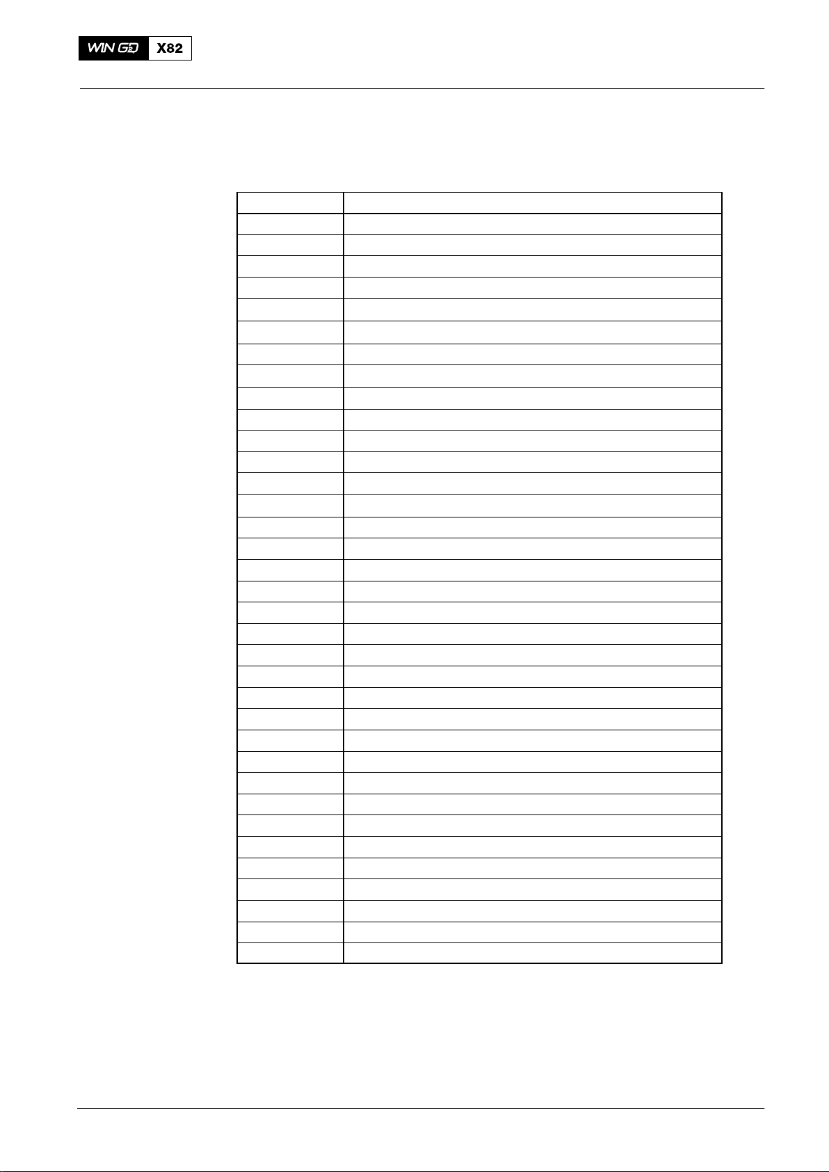
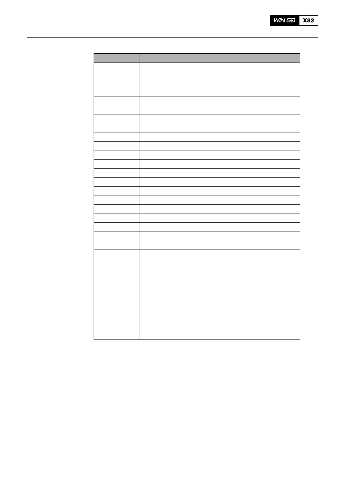
See the table below for the the abbreviations used in this manual. Unit of measures
are not shown in the list.
Operation
0035−1/A1
Abbreviation
AHD Ahead
ALM Alarm
ALM−20 Advanced Lubrication Module−20
AMS Alarm and Monitoring System
AST Astern
ASTM American Society for Testing and Materials
BDC Bottom Dead Center
BN
BSFC Brake Specific Fuel Consumption
CA Crank Angle
CAN−Bus Controller Area Network Bus
CAN M Controller Area Network Module Bus
CAN S Controller Area Network System Bus
CCAI Calculated Carbon Aromaticity Index
CMCR Contract Maximum Continuous Rating
COC Cleveland Open Cup
CSR Continuous Service Rating
DE Driving End
DENIS Diesel Engine CoNtrol and OptImizing Specification
DO Diesel Oil
ECA Emission Control Area
ECR Engine Control Room
EM Engine Margin
FCM-20 Flex Control Module−20
FE Free End
FPP Fixed Pitch Propeller
FQS Fuel Quality Setting
FZG Gear Research Center
HFO Heavy Fuel Oil
HP High Pressure
ICC Intelligent Combustion Control
IMO International Maritime Organisation
ISO International Standard Organisation
LED Light Emitting Diode
LLT Low-load Tuning
Word(s) in Full
Base Number
Winterthur Gas & Diesel Ltd.
1/ 2
2014
Page 30
Abbreviations
Operation0035−1/A1
Abbreviation Word(s) in Full
MARPOL International Convention for the Prevention of Pollution
from Ships
MCM Main Control Module
Modbus Gould-Modicon Fieldbus
MCR Maximum Continuous Rating
MDO Marine Diesel Oil
ME Main Engine
mep Mean effective pressure
MGO Marine Gas Oil
OAT Organic Acid Technology
OM Operational Margin
OMD Oil Mist Detector
PCS Propulsion Control System
PLM Pulse Lubrication Module
PLS Pulse Lubrication System
PMCC Pensky Martens Closed Cup method
RCS Remote Control System
SAC Scavenge Air Cooler
SAE Society of Automotive Engineers
SCS Speed Control System
SHD Shut Down
SIB Shipyard Interface Box
SLD Slow Down
SS Safety System
SSI Synchron Serial Interface
TC Turbocharger
TDC Top Dead Center
VEC Variable Exhaust valve Closing
VEO Variable Exhaust valve Opening
VIT Variable Injection Timing
WECS−9520 Wärtsilä Engine Control System−9520
2014
2/ 2
Winterthur Gas & Diesel Ltd.
Page 31

General
Operation
How to Use the Operation Manual
1. Contents
The Operation Manual, (Operation), contains data and indications about:
D The servicing of the engine during operation
D The necessary media (oil, water, air, fuel)
D The functions of components and systems.
Note: The maintenance and overhaul instructions are found in the Maintenance
Manual.
2. Abbreviations
Some of the abbreviations used in the Operation Manual are given in 0035−1. Other
abbreviations are shown in the related text and the keys to related illustrations.
3. Where to find data
0040−1/A1
You can find the group titles in the Table of Contents 0020−1. You can also look in
The Subject Index 0030−1.
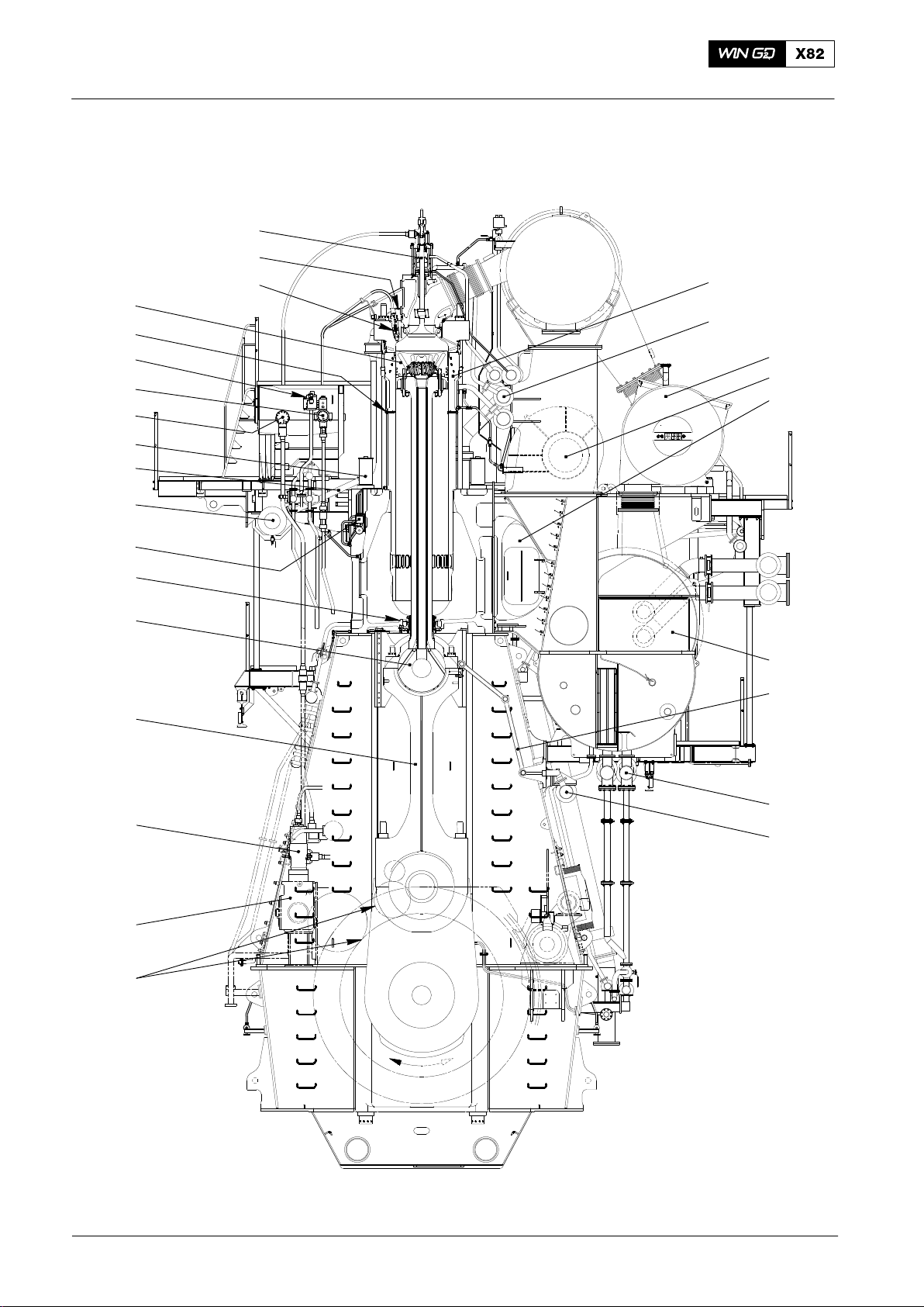
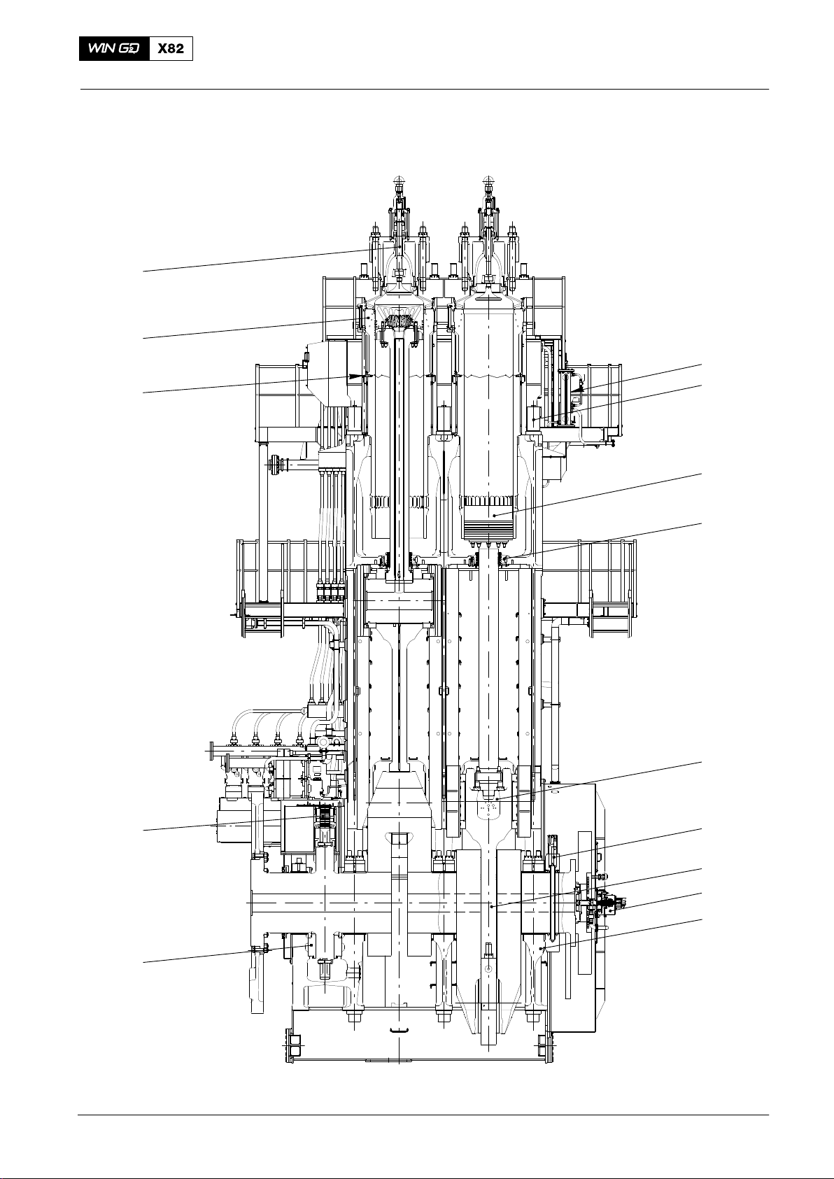
In the cross section and longitudinal section illustrations (see Fig. 1 and Fig. 2),
important components are shown with their group numbers. These group numbers
have hyperlinks to the different groups in the manual, which give more data about the
engine.
For the cross section and longitudinal section illustrations, see pages 2 and 3.
The cross section and longitudinal section illustrations shown can have small
differences because of different engine revisions.
If you have a PDF version of this manual, you can use the Previous View and Next
View buttons on the taskbar to navigate.
Winterthur Gas & Diesel Ltd.
1/ 3
2014
Page 32
How to Use the Operation Manual
4. Cross section
2751−1
2728−1
2722−1
3403−1
2138−1
5562−1
8019−1
8016−1
1903−1
8018−1
4325−1
Operation0040−1/A1
2124−1
8017−1
6500−1
6545−1
6420−1
7218−1
2303−1
3326−1
3303−1
5556−1
5581−1
4104−1
6606−1
3603−1
8345−1
8016−1
2014
Fig. 1: Cross Section
2/ 3
WCH01165
Winterthur Gas & Diesel Ltd.
Page 33
How to Use the Operation Manual
5. Longitudinal section
2751−1
2124−1
2138−1
Operation
0040−1/A1
7218−1
1903−1
4104−1
3403−1
2303−1
3326−1
3140−1
3303−1
1203−1
Winterthur Gas & Diesel Ltd.
Fig. 2: Longitudinal Section
3/ 3
9223−1
1132−1
018.264/09
2014
Page 34

Intentionally blank
Page 35

General
Operation
Short Description of the Engine
1. General
General data about the engine are given as follows:
D The W−X engine is a single acting, two-stroke diesel engine of crosshead design
with exhaust gas turbocharging and uniflow scavenging.
D The engine is reversible and is directly connected to the propeller.
D The W−X concept is based on the Common Rail System, with full electronic
control of the fuel injection system and the exhaust valve operation.
D The engine control can have different remote controls, which are related to our
specifications, from recommended manufacturers.
D If the remote control has a failure, the engine can be controlled with the
emergency control from the local control panel.
D Tie rods hold the bedplate, columns and cylinder block together.
0050−1/A1
D A partition isolates the crankcase from the cylinder block. This partition includes
the piston rod glands for the piston rods.
D The thrust bearing and turning gear are installed on the driving end of the engine.
D The engine control system WECS-9520 controls the exhaust valve operation,
electronic fuel injection and cylinder lubricating system.
D The lubrication oil, coolant water, fuel supply, booster pumps and air
compressors are parts of the engine room installation (ancillary systems).
2. Systems
General data about the systems are given as follows:
D The servo oil system opens the exhaust valves hydraulically. The exhaust valves
are closed pneumatically.
D Servo oil pumps in the supply unit, supply bearing oil at the necessary pressure
through two high pressure (HP) oil pipes to the servo oil rail.
D Bearing oil cools the pistons.
D The fuel pumps in the supply unit, supply high pressure fuel through the HP fuel
pipes to the fuel rail. The fuel rail supplies high pressure fuel to all the injection
valves.
D The servo oil system operates the injection control units.
Winterthur Gas & Diesel Ltd.
D Fresh water cools the cylinder liners and cylinder covers.
D The central fresh water cooling system (closed circuit), or the conventional
sea-water cooling system (direct) with single-stage coolers are used to cool the
scavenge air.
D The WECS-9520 controls the engine start sequence. Compressed air flows
through the starting valve into the cylinders to start the engine.
1/ 2
2017−08
Page 36

Short Description of the Engine
D The exhaust gases flow from the cylinders through the exhaust valves into the
exhaust gas manifold.
D The turbocharger uses the pressure of the exhaust gas to operate the
compressor.
D The scavenge air from the turbocharger flows through the air cooler and water
separator into the air receiver. This air then flows through air flaps and scavenge
ports when the pistons are almost at BDC.
D At low loads, independently operated auxiliary blowers supply air to the scavenge
air space.
Operation0050−1/A1
2017−08
2/ 2
Winterthur Gas & Diesel Ltd.
Page 37
General
Operation
0060−1/A1
Two-stroke Diesel Engine − Operation
1. Piston Movement
1.1 First Stroke (Compression)
The sequence of piston movements during the compression stroke is as follows:
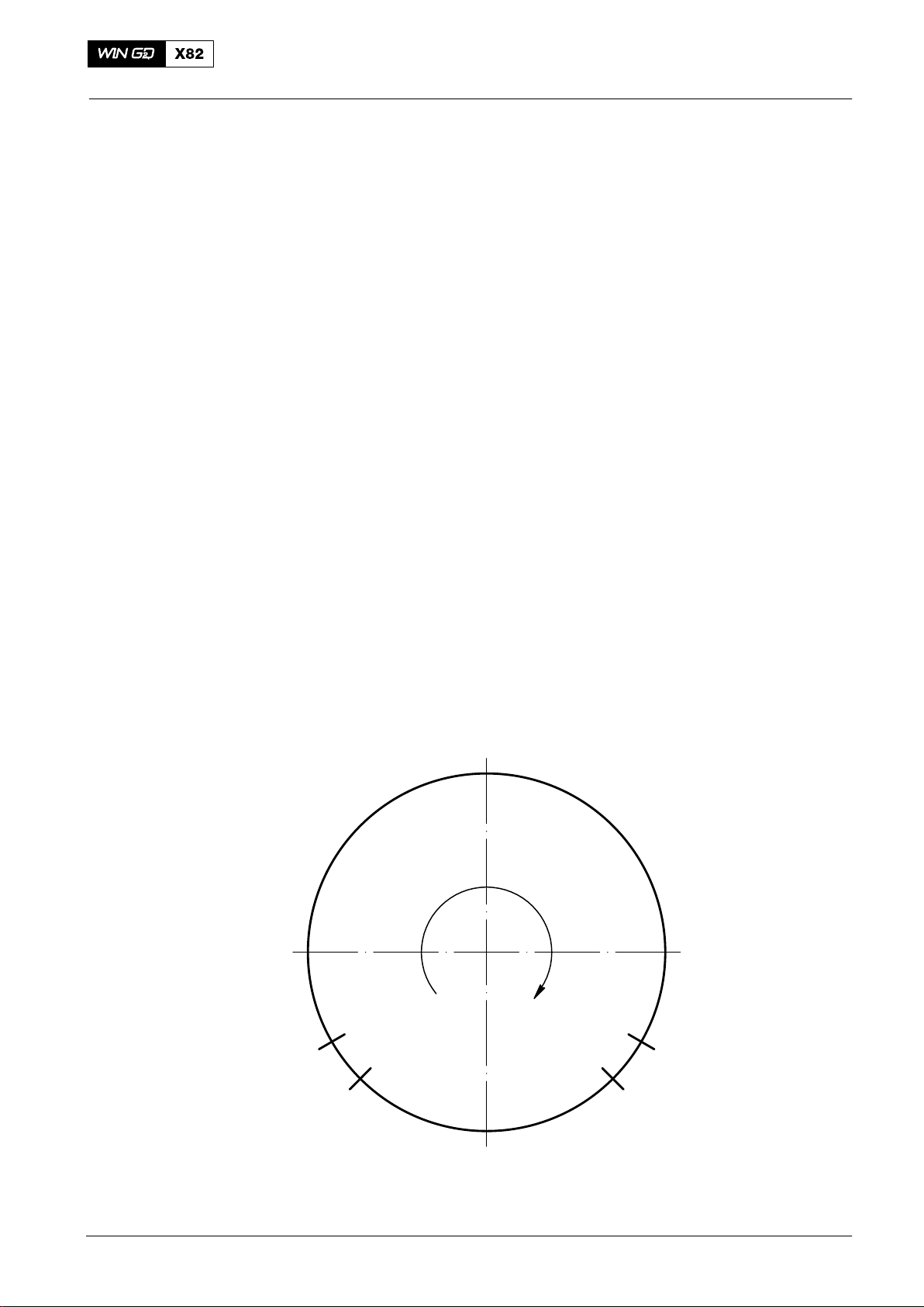
D The piston is at BDC (see Fig. 1).
D The scavenge ports and exhaust valve are open.
D Scavenge air flows into the cylinder and pushes the exhaust gas through the
exhaust valve into the exhaust gas manifold and then to the turbocharger.
D The piston moves up.
D At ES, the piston covers the scavenge ports.
D At AS, The exhaust valve closes and compression starts, which heats the air.
1.2 Second Stroke (Ignition − Combustion − Expansion − Exhaust −
Scavenging)
The sequence of piston movements during the second stroke is as follows:
D When the piston is almost at TDC, fuel is injected into the cylinder.
D The fuel ignites in the compressed, heated air and combustion starts.
D The gases expand and push the piston down.
D At AO, the exhaust valve opens. Exhaust gas flows out of the cylinder into the
exhaust gas manifold.
D At EO, the piston continues to move down to let air in through the scavenge
ports.
D Scavenge air flows into the cylinder and pushes the exhaust gas through the
exhaust valve into the exhaust gas manifold and then to the turbocharger.
See also the schematic diagram in 6500−1 Turbocharging.
TDC
AS
BDC
Fig. 1: Schematic of Engine Operation
AO
EOES
Winterthur Gas & Diesel Ltd.
1/ 1
2014
Page 38

Intentionally blank
Page 39

General
Operation
The Relation between Engine and Propeller
1. General 1..........................................................
2. Fixed Pitch Propeller (FPP) 2........................................
2.1 Continuous Service Rating (CSR) 2............................
2.2 Engine Margin (EM) / Operational Margin (OM) 2................
2.3 Load Range Limits 3..........................................
3. Controllable Pitch Propeller (CPP) 4.................................
3.1 Load Ranges 4...............................................
3.2 Control System 5.............................................
1. General
There is a specified relation between the propeller speed and the absorbed power in
ships that have fixed pitch propellers. The relation is between the propeller and the
speed at which it turns.
The formula that follows (where P = power and n = speed) gives an approximate
result, which is sufficient for conventional vessels:
P
1
=
P
2
3
n
1
n
2
0070−1/A1
The graph from this formula is known as the propeller characteristic.
If the engine is in good condition, correctly supplied with air (i.e. turbocharger(s) are in
good condition and the resistance of the air and exhaust lines is in the specifications)
and the fuel injection quantity is correctly adjusted (see the shop test protocol), then
the mean effective pressure (mep) developed during service conditions (in
accordance with the specified load indication), is related to the approximate mep for
this position on the test bed.
In the diagram (see paragraph 2), the propeller property line through the CMCR point
(100% power at 100% engine speed) is known as the nominal propeller characteristic.
Engines which are to be used for the propulsion of vessels with fixed propellers have
a load applied on the test bed in accordance with this propeller characteristic.
However, during sea trial of a new ship with a smooth and clean hull, the power
requirement is lower and the operation point is below the nominal propeller
characteristic.
During service, a higher torque will be necessary for the propeller to keep its speed
than at the time of the sea trial (sea margin) because:
D There are changes in wake flow conditions because of marine growth on the hull.
D The cargo load has an effect on the depth of the vessel in the water.
D The propeller has a rough surface or has mechanical damage.
D The vessel operates in bad sea and weather conditions.
D The vessel operates in shallow water. The mep of the engine (and thus the fuel
injection quantity) will increase. In such a condition, the operating point will then
be at the left of the initial propeller curve which was calculated during sea trials.
A hull that was cleaned and painted will help to decrease the resistance as the vessel
moves through the water. It is not possible, to get the hull back to its initial condition.
Because the thermal load of the engine is related to the mep, the position of the
operating point is also important. The air supply to the engine and the operating
conditions will become unsatisfactory if the operation point is far above the propeller
curve.
To get the best conditions, the operation point of the engine for service range must be
on or below the nominal propeller characteristic.
Winterthur Gas & Diesel Ltd.
1/ 5
2014
Page 40
The Relation between Engine and Propeller
2. Fixed Pitch Propeller (FPP)
2.1 Continuous Service Rating (CSR)
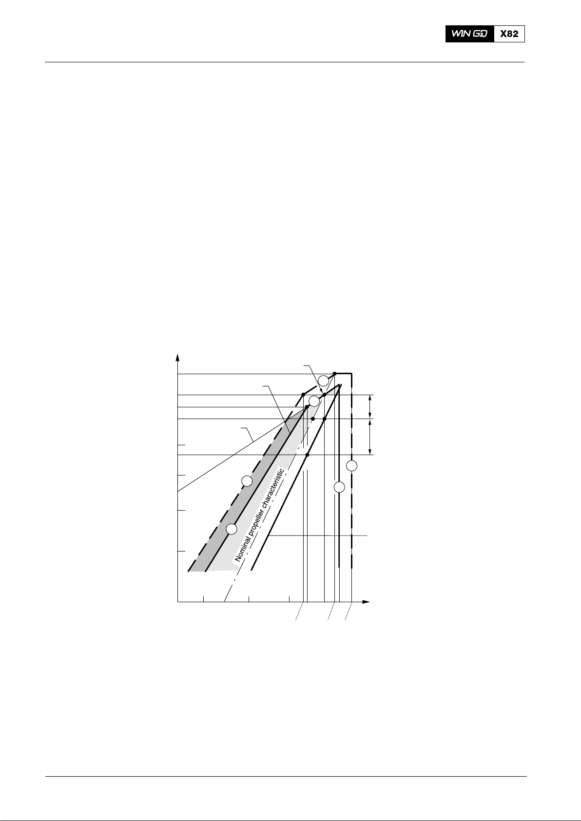
Point A (see Fig. 1) shows the power and speed of a ship that operates at contractual
speed in calm seas with a new clean hull and propeller. A power / speed combination
at point D is necessary for the same ship at the same speed during service conditions
with aged hull and average weather. Point D is then the CSR point.
2.2 Engine Margin (EM) / Operational Margin (OM)
Most owners specify the contractual loaded service speed of the ship at 85% to 90%
of the contract maximum continuous rating (CMCR). The remaining 10% to 15% of
power can be used to catch up with changes in schedules or for the timing of dry-dock
intervals. This margin is usually subtracted from the CMCR. Thus, to get the 100%
power line, you divide the power at point D by between 0.85 to 0.90.
Engine power
[% Rx]
Operation0070−1/A1
Load range limits with load diagram of an
engine related to a specified rating point Rx
110
CMCR (Rx)
Engine load range
100
95
90
Constant
80
torque
76.5
70
6
60
5
50
40
65 70 80 90 95 100 104
F10.5249
93.8
2
1
D
A
103.2
10% EM / OM
B
15% SM
4
3
Propeller curve
without SM
Engine speed
[% Rx]
108
2014
EM Engine Margin
OM Operational Margin
SM Sea Margin
Fig. 1: Schematic Diagram of Speed / Power Relation (FPP)
2/ 5
Winterthur Gas & Diesel Ltd.
Page 41

The Relation between Engine and Propeller
2.3 Load Range Limits
When the engine has the best values at CMCR (Rx), the limits that follow give the
load range of the engine:
D Line 1 is a constant mep or torque line through CMCR from 100% speed and
power down to 95% speed and power.
D Line 2 is the overload limit. This is a constant mep line from 100% power and
93.8% speed to 110% power and 103.2% speed. 103.2% speed is the
intersection point between the nominal propeller property and 110% power.
D Line 3 is the 104% speed limit where an engine can operate continuously. For Rx
with decreased speed (N
but, the torsional vibration must not be more than the specified limits.
D Line 4 is the overspeed limit. The overspeed range between 104 (106) and 108%
speed is only permitted during sea trials if necessary. This is to demonstrate the
speed of the ship at CMCR power with a light running propeller in the presence of
authorized representatives of the engine builder. The torsional vibration must not
be more than the specified limits.
Operation
CMCR
0.98 N
0070−1/A1
) this limit can be extended to 106%,
MCR
D Line 5 is the permitted torque limit from 95% power and speed to 45% power and
70% speed. This shows a curve defined by the equation: P
= (N2/N1)
2/P1
2.45
.
When the engine speed and power is near the data in Line 5 there will be a
decrease in scavenge air, which has an effect on the engine. The area between
Lines 1, 3 and 5 show the range in which the engine must be operated. The area
in the nominal propeller characteristic, 100% power and Line 3 is recommended
for continuous operation. The area between the nominal propeller property and
Line 5 must be reserved for acceleration, shallow water and usual flexibility of
operation.
D Line 6 gives the equation: P
= (N2/N1)
2/P1
2.45
through 100% power and 93.8%
speed and the maximum torque limit in transient conditions. The area above
Line 1 is the overload range. You must only operate the engine in this range for a
maximum of one hour during sea trails in the presence of authorized
representatives of the engine builder. The area between Lines 5 and 6 and the
constant torque line (shown as a dark area) must only be used for transient
conditions, i.e. during fast acceleration. This range is known as the service range
with operational time limit.
Winterthur Gas & Diesel Ltd.
3/ 5
2014
Page 42
The Relation between Engine and Propeller
3. Controllable Pitch Propeller (CPP)
3.1 Load Ranges
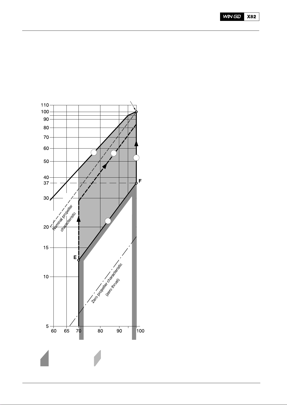
After engine start, the engine is operated at an idle speed of up to 70% of the rated
engine speed with zero pitch. From idle speed, the propeller pitch must be increased
with constant engine speed to the minimum at point E, the intersection with Line 9.
Operation0070−1/A1
Engine power [% Rx]
CMCR (Rx)
5
7
8
9
D Line 9 is the bottom load limit between
70% and 100% speed, with a pitch
position that at 100% speed, the
minimum power at point F is 37%. The
formula shown in paragraph 1 is used for
this calculation.
D Along Line 8 the power increase from
37% (point F) to 100% power (CMCR) at
100 % speed is the constant speed mode
for shaft generator operation
D Line 5 is the top load limit and relates to
the permitted torque limit.
D The area between 70% and 100% speed
and between Line 5 and Line 9 shows the
area that an engine with a CPP must be
operated.
Line 7 shows a typical combinator curve for
variable speed mode.
Maneuvering at maximum speed with low or
zero pitch is not permitted. Thus,
installations with main engine-driven
generators must have a frequency
converter when electrical power is to be
supplied (e.g. to thrusters) at constant
frequency during manoeuvring. As an
alternative, power from auxiliary engines
can be used for this purpose.
Engine speed [% Rx]
Engine operation
is not permitted
Fig. 2: Schematic Diagram of Speed / Power Relation (CPP)
2014
Operate the engine
in this area when a
4/ 5
For test purposes, the engine can be
operated at rated speed and low load during
a one-time period of 15 minutes on the
testbed (e.g. NO
minutes during dock trials (e.g. shaft
generator adjustment) when there are an
authorized representatives of the engine
builder on board. More requests must be
agreed from Winterthur Gas & Diesel Ltd.
measurements) and 30
x
Winterthur Gas & Diesel Ltd.
Page 43

The Relation between Engine and Propeller
3.2 Control System
The CPP control functions are usually part of the engine control system and include
the functions in the paragraphs that follow.
3.2.1 Combinator Mode 1
Combinator mode for operation without a shaft generator. A combinator curve that
includes an applicable light running margin can be set in the permitted operation area,
Line 7 (see Fig. 2).
3.2.2 Combinator Mode 2
An optional mode used in connection with shaft generators. During maneuvering, the
combinator curve follows the Line 9. At sea the engine is operated between point F
and 100% power (Line 8) at constant speed .
For manual and/or emergency operation, different setpoints for speed and pitch are
usually supplied.
Operation
0070−1/A1
An alarm is also usually given in the main engine safety system, or the alarm and
monitoring system when the engine operates for more than three minutes in the
operation area that is not permitted. If the engine operates for more than five minutes
in the operation area that is not permitted, the engine speed must be decreased to
idle speed (less than 70% ).
Winterthur Gas & Diesel Ltd.
5/ 5
2014
Page 44

Intentionally blank
Page 45
General
Basic Engine Data
1. General
Operation
0080−1/A1
DRAWN FOR
7 CYLINDERS
DRIVING
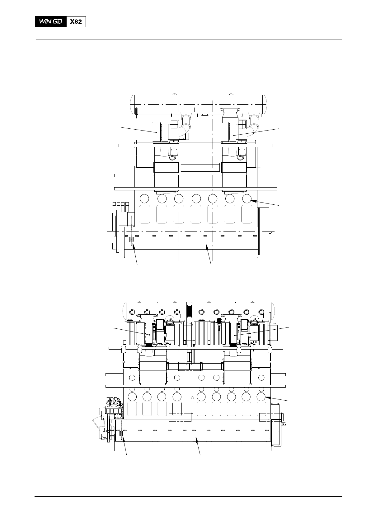
END
Turbocharger 1
1 2 3 4 5 6 7
1
Thrust Bearing
Pads
6543287 9
Main Bearing
Numbering
Turbocharger 2
Cylinder Numbering
FREE
END
Turbocharger 1
DRAWN FOR
9 CYLINDERS
DRIVING
END
Winterthur Gas & Diesel Ltd.
1 2 3 4 5 6 7 8 9
Thrust Bearing
Pads
6543287
Main Bearing
Numbers
Fig. 1: Outline View
1/ 4
91
Turbocharger 2
Cylinder Number
FREE
END
10 11 12
WCH02734
2014-09
Page 46
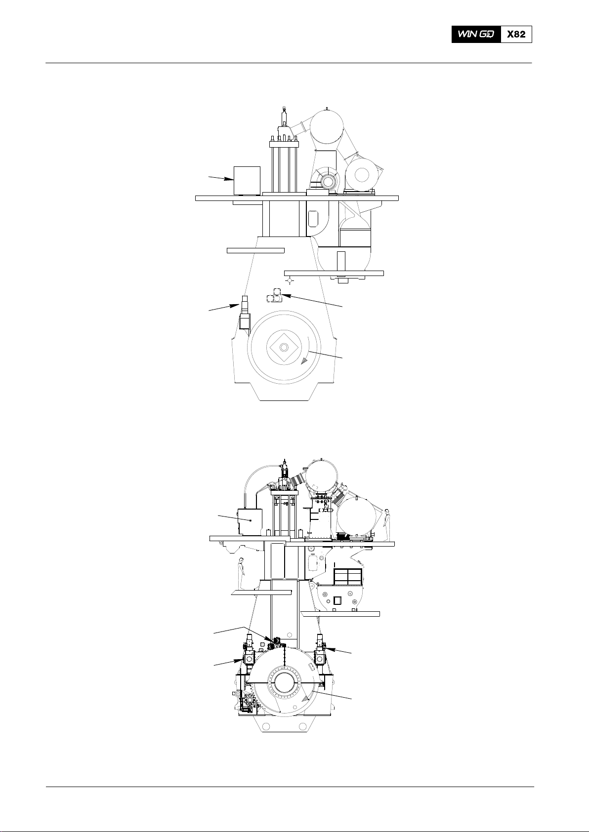
Engine Numbering and Designations
Rail Unit
Operation0080−1/A1
DRAWN FOR
6 CYLINDERS TO
8 CYLINDERS
Fuel Pump Unit
FUEL
SIDE
EXHAUST
SIDE
Servo Pump Unit
Clockwise Rotation
017.921/08
DRAWN FOR
9 CYLINDERS
Rail Unit
FUEL
SIDE
Servo Pump Unit
Fuel Pump Unit
(Fuel Side)
EXHAUST
SIDE
Fuel Pump Unit
(Exhaust Side)
Clockwise Rotation
WCH02734
Fig. 2: Outline View
2014-09
2/ 4
Winterthur Gas & Diesel Ltd.
Page 47
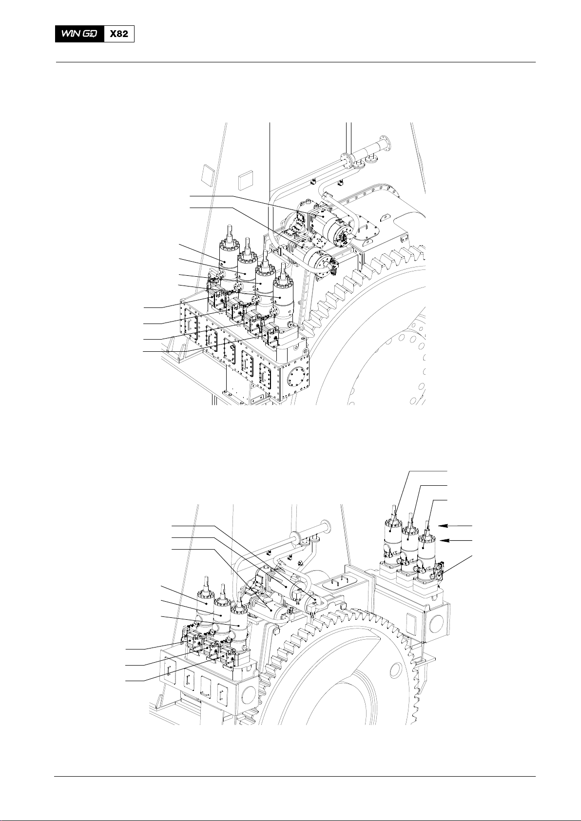
Engine Numbering and Designations
2. Flex Parts
DRAWN FOR
6 CYLINDERS TO
8 CYLINDERS
Servo Oil Pump 2
Servo Oil Pump 1
Fuel Pump A1
Fuel Pump A2
Fuel Pump A3
Fuel Pump A4
Actuator A1
Actuator A2
Actuator A3
Actuator A4
FUEL SIDE
Operation
0080−1/A1
EXHAUST SIDE
DRAWN FOR
9 CYLINDERS
Servo Oil Pump 3
Servo Oil Pump 2
Servo Oil Pump 1
Fuel Pump A1
Fuel Pump A2
Fuel Pump A3
Actuator A1
Actuator A2
Actuator A3
017.931/08
DRIVING END
Fuel Pump B1
Fuel Pump B2
Fuel Pump B3
Actuator B1
Actuator B2
Actuator B3
EXHAUST SIDE
FUEL SIDE
Winterthur Gas & Diesel Ltd.
DRIVING END
Fig. 3: Flex Parts
3/ 4
016.834/08
2014-09
Page 48

Engine Numbering and Designations
Operation0080−1/A1
Crank Angle Sensors
Sensor 2
(GT5127C)
FREE END
Fig. 4: Flex Parts
Sensor 1
(GT5126C)
FUEL SIDE
013.150/05
2014
4/ 4
Winterthur Gas & Diesel Ltd.
Page 49
Prepare the Engine for Operation
Prepare for Engine Start after a Short Shut-down Period (One or More Days)
1. Start Position
For the start position, the engine must be in the condition that follows:
D All components that had an overhaul are correctly assembled and installed. All
components that had an overhaul have had tests or checks to make sure that
they operate correctly.
D All devices, tools and materials are removed from the engine.
D The fuel pump settings and the connections of the actuators to the regulating
linkages are correct.
Operation
CAUTION
Damage Hazard: The vent valves 2.21 and 2.27 in the start air line
must be open when the starting air shut-off valve 2.03 is in the
manually CLOSED position (see the Control Diagram 4003−2).
0110−1/A1
2. Prepare for Operation
1) Do a check of the fluid levels of all the tanks in the engine systems (and the
leakage drain tanks).
2) Make sure that all the shut-off valves for the coolant water system and lubrication
oil system are in the correct position.
3) Open the air supply from the shipboard system and from the starting air
bottles [9.01] to the control air supply A.
4) Open the shut-off valve 36HB at connection A1 and set the 3/2-way shut-off valve
4.08 to the operation position (see Control Air Supply 4605−1).
5) Heat the lubrication oil to approximately 35_C (through the lube oil separator or
heaters in oil drain tank if installed).
6) Heat the cylinder coolant water to a minimum of 60_C.
7) Set to on the remote control system and the WECS−9520.
8) In the power supply box E85, set all circuit breakers to on.
9) Make sure that the two green LEDs on all FCM−20 come on.
Note: The FCM−20 can operate if no red LEDs come on after the countdown
process.
10) Prepare the servo oil system (see 0130−1).
11) Start the pumps for the cylinder coolant water and bearing oil. Set the pressures
to their usual values (see the Operating Data Sheet 0250−1).
12) Set to on the control box for the automatic filter (see the documentation of the
automatic filter manufacturer).
13) Set to on the main switch of the servo oil service pump.
14) Prepare the cylinder lubrication system (see 0140−1).
15) Prepare the fuel system (see 0120−1).
16) Make sure that you correctly release all air from all systems.
17) Make sure that there is an air spring supply and make sure that all exhaust
valves are closed.
18) In the remote control, use the parameter Exv. A/M Cmd to manually open and
close all exhaust valves 4.01 until all air is released in the hydraulic actuators
(see 4002−3 User Parameters and Maintenance Settings, paragraph 1).
Note: You cannot start the engine if the exhaust valves are not fully closed.
Winterthur Gas & Diesel Ltd.
1/ 3
2014
Page 50
Operation0110−1/A1
Prepare for Engine Start after a Short Shut-down Period (One or More Days)
19) Open the indicator valve on all cylinder covers.
WARNING
Injury Hazard: Before you operate the turning gear, make sure
that no personnel are near the flywheel.
20) Use the turning gear to turn the engine a minimum of one full turn to make sure
that all the running gears will operate correctly.
Note: Oil, water or fuel must not come out of the indicator valves.
21) If water oil or fuel comes out of the indicator valves, do a check of the related
cylinder liner, cylinder cover, piston or injection valves.
22) Set the cylinder lubrication to on.
23) Close the indicator valves on all cylinders.
24) Make sure that all the clamps lock the crankcase doors.
25) Make sure that the fuel pump regulating linkage moves freely in the spring links.
26) Check the pressure in the starting air bottles and open their drains until any
condensate has been drained.
27) Open the drain and test valve 2.06 to drain possible condensate water.
28) Close the drain and test valve 2.06.
29) Close the venting valves 2.21 and 2.27.
30) Open the shut-off valves on the starting air bottles 9.01.
31) Turn the handwheel 2.10 of the shut-off valve for starting air 2.03 to the position
AUTOMAT.
32) Make sure that the pressure gauges on the instrument panel show starting air
pressure and control air pressure.
33) Make sure that a pressure indication shows on the pressure gauges for the
control air supply.
The different circuits are:
D Air spring air
D Control air.
For the necessary pressures, see the Operating Data Sheet 0250−1.
34) Set the switches on the control panels for the auxiliary blowers to AUTOMAT.
35) Set to off the servo oil service pump.
2014
36) Disengage the turning gear and lock the lever.
37) Open the test valve 2.06 of the shut-off valve for starting air 2.03 for a short time.
Make sure that you can hear the valve open.
38) Close the test valve 2.06.
2/ 3
Winterthur Gas & Diesel Ltd.
Page 51
Operation
Prepare for Engine Start after a Short Shut-down Period (One or More Days)
WARNING
Injury Hazard: Before you operate the engine make sure that no
personnel are near the flywheel.
39) In WECS−9520 manual control panel (on the local control panel), push the
SLOW TURNING button (4618−1, Local Control Panel, paragraph 2.1). The
engine will slowly turn one time (see also Slow Turning 0220−1).
40) Make sure that at the location where you want to start the engine, the related
WECS−9520 control panel has control (e.g. the bridge, control room or local
control panel).
41) Tell personnel on the bridge that the engine is prepared for operation.
0110−1/A1
Winterthur Gas & Diesel Ltd.
3/ 3
2014
Page 52

Intentionally blank
Page 53

Operation
0120−1/A1
Prepare the Engine for Operation 6-cylinders to 8-cylinders
Prepare the Fuel System for Operation
1. Prepare the Fuel System
1.1 Diesel Operation
1) See 0720−1, Fig. 1.
2) Set the three-way valve (16) in the suction line of the low pressure feed
pump (19) to let diesel oil flow from the daily tank (6) to the pump and to the
mixing unit (21).
3) Make sure that the shut-off valves upstream and downstream of the engine are
open.
4) Start the pumps (19) and (22).
5) Drain the daily tanks and the mixing unit.
6) Use the pressure regulating valve (17) to set the pressure in the fuel system.
Note: When the engine operates with diesel oil (and low fuel temperature) a
small over-pressure is sufficient. If a change-over to heavy fuel oil is
necessary, the setting of the usual pressure is recommended from the
start.
7) Use the pressure retaining valve (27) to set the fuel pressure at the fuel pump
inlet (see 0250−1 Operating Data Sheet).
1.2 Heavy Fuel Operation
1) See 0720−1, Fig. 1.
Note: The fuel system is not ready for operation until the heavy fuel upstream
of the fuel pumps is at the necessary temperature (see 0710−1,
paragraph 3.1 Viscosity-Temperature Diagram).
After a shut-down period of more than 24 hours heat the high pressure circuit on the
engine for a minimum of four to six hours. Do not try to start the engine on heavy fuel
before you heat the fuel.
2) Set to on all heaters in the HFO system.
3) Set to on the heating for the fuel system on the engine (fuel rail 3.05 (13), HP fuel
pipes 3.29 (8) and the fuel leakage system (see 8019−1).
4) Do a check of the steam pipes to make sure they are tight. If leaks are found,
they must be repaired before the first commissioning or after maintenance on the
fuel system.
5) Set the three-way valve (16) in the suction line of the low pressure feed
pump (19) so that HFO flows from the daily tank (3) to the feed pump (19) and
the mixing unit (20).
6) Drain the settling tank, daily tanks and mixing unit.
Winterthur Gas & Diesel Ltd.
7) Make sure that the shut-off valves upstream and downstream of the engine are
open.
8) Start the pumps (19) and (22).
9) Heat the HFO. This is necessary to get the HFO to the necessary viscosity (see
0270−1 Change-over from Diesel Oil to Heavy Fuel Oil).
10) Use the pressure regulating valve (17) to set the pressure in the fuel system.
11) Use the pressure retaining valve (27) to set the fuel pressure at the fuel pump
inlet (see 0250−1 Operating Data Sheet).
1/ 2
2017−08
Page 54

Operation0120−1/A1
Prepare the Fuel Oil System for Operation 6-cylinders to 8-cylinders
2. High Pressure Circuit
1) See 8019−1 Fuel System Fig. 1.
2) Make sure that the drain valve 3.65 (21) is closed.
3) At the driving end of the fuel rail 3.05 (13), make sure that the drain
screw 3.82 (22) is closed. If necessary, torque the drain screw 3.82 (22) to
200 Nm.
3. Vent of the Fuel Oil System
Note: The numbers in the parentheses ( ) below refer to items in 0720−1, Fig. 1
Configuration of fuel oil system. The numbers in the square brackets [ ]
refer to items in 4003−2, Control Diagrams. Numbers that do not have
parenthesis and square brackets refer to items in 8019−1, Fig. 1.
The fuel oil system can be vented manually as follows:
D Make sure that the engine control system WECS−9520 is set to on.
D Start the low pressure pump (19) and the booster pump (22).
When the booster pump (22) starts, fuel flows through the fuel pumps 3 [3.14], then
flows through the HP fuel pipes 8 [3.29] into the fuel rail 13 [3.05].
D Use the hand lever on the fuel shut-down pilot valve 25 [3.08] to vent the fuel rail
through the fuel pressure control valve 24 [3.06].
2017−08
2/ 2
Winterthur Gas & Diesel Ltd.
Page 55

Operation
0120−1/A2
Prepare the Engine for Operation 9-cylinders
Prepare the Fuel Syst
em for Operation
1. Prepare the Fuel System
1.1 Diesel Operation
1) See 0720−1, Fig. 1.
2) Set the three-way valve (16) in the suction line of the low pressure feed
pump (19) to let diesel oil flow from the daily tank (6) to the pump and to the
mixing unit (21).
3) Make sure that the shut-off valves upstream and downstream of the engine are
open.
4) Start the pumps (19) and (22).
5) Drain the daily tanks and the mixing unit.
6) Use the pressure regulating valve (17) to set the pressure in the fuel system.
Note: When the engine operates with diesel oil (and low fuel temperature) a
small over-pressure is sufficient. If a change-over to heavy fuel oil is
necessary, the setting of the usual pressure is recommended from the
start.
7) Use the pressure retaining valve (27) to set the fuel pressure at the fuel pump
inlet (see 0250−1 Operating Data Sheet).
1.2 Heavy Fuel Operation
1) See 0720−1, Fig. 1.
Note: The fuel system is not ready for operation until the heavy fuel upstream
of the fuel pumps is at the necessary temperature (see 0710−1,
paragraph 3.1 Viscosity-Temperature Diagram).
After a shut-down period of more than 24 hours heat the high pressure circuit on the
engine for a minimum of four to six hours. Do not try to start the engine on heavy fuel
before you heat the fuel.
2) Set to on all heaters in the HFO system.
3) Set to on the heating for the fuel system on the engine (fuel rail 3.05 (15), HP fuel
pipes 3.29 (10) and the fuel leakage system (see 8019−1).
4) Do a check of the steam pipes to make sure they are tight. If leaks are found,
they must be repaired before the first commissioning or after maintenance on the
fuel system.
5) Set the three-way valve (16) in the suction line of the low pressure feed
pump (19) so that HFO flows from the daily tank (3) to the feed pump (19) and
the mixing unit (20).
6) Drain the settling tank, daily tanks and mixing unit.
7) Make sure that the shut-off valves upstream and downstream of the engine are
open.
Winterthur Gas & Diesel Ltd.
8) Start the pumps (19) and (22).
9) Heat the HFO. This is necessary to get the HFO to the necessary viscosity (see
0270−1 Changing Over from Diesel Oil to Heavy Fuel Oil).
10) Use the pressure regulating valve (17) to set the pressure in the fuel system.
11) Use the pressure retaining valve (27) to set the fuel pressure at the fuel pump
inlet (see 0250−1 Operating Data Sheet).
1/ 2
2017−08
Page 56

Operation0120−1/A2
Prepare the Fuel Oil System for Operation 9-cylinders
2. High Pressure Circuit
1) See 8019−1 Fuel System Fig. 1.
2) Make sure that the drain valve 3.65 (30) is closed.
3) At the driving end of the fuel rail 3.05 (15), make sure that the drain
screw 3.82 (31) is closed. If necessary, torque the drain screw 3.82 (31) to
200 Nm.
4) Make sure that the shut-off valves 3.33-3 to 3.33-6 (26), (27), (28) and (29), on
the connecting pipe (14) are tight and open. If necessary, torque the stop
valves 3.33-3 to 3.33-6 (26), (27), (28) and (29) to 100 Nm.
3. Vent of the Fuel Oil System
Note: The numbers in the parentheses ( ) below refer to items in 0720−1, Fig. 1
Configuration of fuel oil system. The numbers in the square brackets [ ]
refer to items in 4003−2, Control Diagrams. Numbers that do not have
parenthesis and square brackets refer to items in 8019−1, Fig. 1.
The fuel oil system can be vented manually as follows:
D Make sure that the engine control system WECS−9520 is set to on.
D Start the low pressure pump (19) and the booster pump (22).
When the booster pump (22) starts, fuel flows through the fuel pumps 3 [3.14], then
flows through the HP fuel pipes 10 [3.29] into the fuel rail 15 [3.05].
D Use the hand lever on the fuel shut-down pilot valve 34 [3.08] to vent the fuel rail
through the fuel pressure control valve 33 [3.06].
2017−08
2/ 2
Winterthur Gas & Diesel Ltd.
Page 57

Prepare the Engine for Operation
Prepare the Servo Oil System
1. Servo Oil System − Checks
1.1 6-cylinder to 8-cylinder engines
For more data, see 8016−1 Fig. 3 and Fig. 4 and 4003−2, Control Diagram.
Do the checks that follow:
1) Make sure that the stop valve 4.37 (14), upstream of the automatic filter 4.20 (1)
is open.
2) Make sure that the stop valve 4.80 (15) downstream of the automatic
filter 4.20 (1) is open.
3) At the free end of the servo ol rail 4.11 (7), make sure that the stop
valve 3.40 (27) is closed and the nut with the conical plug is installed.
4) At the driving end of the servo ol rail 4.11 (7), make sure that the drain
screw 4.82 (31) has a torque of 200 Nm (see 8016−1 Servo oil rail − fill and drain,
paragraph 6).
Operation
0130−1/A1
5) Make sure that the ball valves 3.38 (21) and 3.27 (22) upstream and downstream
of the injection control unit 3.02 (11) are open.
1.2 9-cylinder engines
For more data, see 8016−1/A2 Fig. 3 and Fig. 4 and 4003−2, Control Diagram.
Do the checks that follow:
1) Make sure that the stop valve 4.37 (15), upstream of the automatic filter 4.20 (1)
is open.
2) Make sure that the stop valve 4.80 (16), downstream of the automatic
filter 4.20 (1) is open.
3) Make sure that the stop valves 4.26-3 to 4.26-6 (18), (19), (20) and (21), on the
connecting pipe (8) are tight and open. If necessary, torque the stop
valves 4.26-3 to 4.26-6 (18), (19), (20) and (21) to 100 Nm.
4) At the free end of the servo ol rail 4.11 (7), make sure that the stop
valve 3.40 (33) is closed and the nut with the conical plug is installed.
5) At the driving end of the servo ol rail 4.11 (7), make sure that the drain
screw 4.82 (37) has a torque of 200 Nm (see 8016−1 Servo oil rail − fill and drain,
paragraph 6).
6) Make sure that the ball valves 3.38 (26) and 3.27 (27) upstream and downstream
of the injection control unit 3.02 (12) are open.
Winterthur Gas & Diesel Ltd.
1/ 1
2014
Page 58

Intentionally blank
Page 59

Prepare the Engine for Operation
Prepare the Cylinder Lubricating System
For more data, see 7218−1 Cylinder Lubrication, Fig. 1, Fig. 2, Fig. 3, Fig. 4 and
Fig. 8. Make sure that:
1) The WECS−9520 engine and remote control systems are set to on.
2) The servo oil service pump 4.88 operates.
Do the checks that follow:
1) Make sure that on all ALM−20 the green LEDs come on.
2) Make sure that the ball valve 4.30-5 (5) is open (see Fig. 2).
3) Make sure that the ball valve 4.30-6 is open (only for 9-cylinder engines) (see
4003−3 Cylinder Lubrication).
4) Make sure that ball valve (5), downstream of the lubricating oil filter 8.17, is open
(see Fig. 3).
5) Make sure that the ball valve (9), downstream of the measurement tube (4), is
open (see Fig. 3).
6) Make sure that the shut-off valve (6) (to the servo oil inlet of the lubricating
pumps 8.06) is open (see Fig. 4).
Operation
0140−1/A1
7) Make sure that the ball valve (7) (lubricating oil pipe to the exhaust valve) is open
(see Fig. 8)
8) Make sure that the lubricating oil filter 8.17 and the measurement tube (4) have
no air (see Fig. 3).
9) Make sure that the lubricating pumps 8.06 have no air (servo and lubricating oil).
10) Make sure that the lubricating oil pipes to the lubricating quills have no air.
Note: You must only do the air removal procedure:
D Before first commissioning
D After maintenance
D After a long shut-down period
D When there are problems during operation (pressure, feed rate).
Winterthur Gas & Diesel Ltd.
1/ 1
2014
Page 60

Intentionally blank
Page 61

Operation during Usual Conditions
General Data
The data that follow are about engine operation during usual conditions e.g. all
cylinders operate correctly:
D 0210−1 Safety Precautions and Warnings
D 0220−1 Slow Turning
D 0230−1 Starting
D 0240−1 Usual Operation.
During maneuvering, it is possible to operate the engine from the control room, the
bridge or the local maneuvering stand.
For operation during unusual conditions, see 0500-1.
Operation includes all maneouvers from the first start at cast off until the last
maneuver when the vessel is moored.
The engine is designed to operate with heavy fuel oil (HFO) from pier-to-pier, i.e.
without a change-over to diesel oil.
When the engine is at a standstill, the fuel flows through the fuel pumps if the booster
pump operates.
Operation
0200−1/A1
The necessary conditions of HFO before operation are as follows:
D The HFO is correctly treated.
D The HFO is kept at the correct temperature during the full in-service period,
which includes manoeuvring and stand-by.
For more data, see 0710−1 Diesel Engine Fuels and 0720−1 Fuel Treatment and Fuel
Oil System.
Winterthur Gas & Diesel Ltd.
1/ 1
2014
Page 62

Intentionally blank
Page 63
Operation
Operation
Safety Precautions and Warnings (General Data)
1. General 1..........................................................
2. Warnings 1.........................................................
3. Lighting 2..........................................................
4. Clean Areas 2......................................................
5. Fire 2..............................................................
6. Tools 3.............................................................
7. Spare Parts 3.......................................................
8. Crankcase Doors − Open 3..........................................
9. Temperature 4......................................................
10. Crankcase, Cylinder, Exhaust Pipes and Scavenge air Receiver 4......
11. Carbon Dioxide (CO2) Gas 4.........................................
12. Crankcase Doors − Close 4..........................................
13. Turning Gear 5.....................................................
14. Instruments 5......................................................
15. Frost Hazard 5.....................................................
0210−1/A1
1. General
A correctly maintained engine gives problem-free and safe operation. Use the data
given below as a guide to the maintenance personnel.
For more data about the general maintenance procedures, see the Maintenance
Manual 0011−1 and 0012−1.
2. Warnings
WARNING
Injury Hazard. When you remove valves from the cylinder cover,
do not let oil or fuel fall on to the hot piston. This can cause an
explosion.
WARNING
Injury Hazard: If an oil mist detector activates an alarm, keep
away from engine. There is a risk of explosion. Do not go into the
areas adjacent to the explosion relief valves (see 0460−1
Instructions about the Prevention of Crankcase Explosions).
WARNING
Injury Hazard. Be careful when you disassemble the engine
without the correct tools and/or the necessary precautions.
Compressed springs can suddenly expand and cause injury.
Winterthur Gas & Diesel Ltd.
WARNING
Injury Hazard. When you open valves and shut-off devices, hot
fluids or gases can be released. To prevent injury, always open
slowly the valves and shut-off devices and look at the direction
the medium is released.
Make sure that you read the maintenance instructions for the related parts.
1/ 5
2015-07
Page 64
Operation0210−1/A1
Safety Precautions and Warnings (General Information)
3. Lighting
There must be good permanent lighting. Also, hand lamps must be available at
different locations in the engine room.
4. Clean Areas
Damage Hazard. Do not use water or cleaning fluids to clean the
UNIC electronic control boxes on the rail unit. Damage can occur
if fluids go into these control boxes.
Always keep the engine as clean as possible.
Keep the UNIC electronic control boxes on the rail unit clean and dry.
You must repair all leaks as soon as possible.
Dust, sand and chemical vapors must not go into the engine room.
CAUTION
5. Fire
Make sure that you know the fire fighting instructions.
Before you do welding work or work that causes sparks, make sure that there are no
explosive fluids in the work area.
Make sure that fire fighting equipment is immediately available if you must do work
that causes sparks in the engine room.
Some components e.g. the turbocharger silencer and UNIC electronic control boxes,
must be protected with an applicable cover.
Keep covers and casings closed until the engine has cooled to decrease the risk of
fire or explosions.
CAUTION
Injury Hazard. Be careful when you use paints and solvents in the
engine room. These materials are flammable.
CAUTION
Injury Hazard. Insulation material that is soaked with oil or fuel is
flammable and must be replaced.
2015-07
The engine room and the area below the floor plates must be kept clean. This will
help prevent a fire in the engine room and in different areas.
Make sure that no fire extinguisher gases can be automatically released when
personnel are in the engine room.
Make sure that the emergency exits are clearly marked.
2/ 5
Winterthur Gas & Diesel Ltd.
Page 65
Operation
Safety Precautions and Warnings (General Information)
6. Tools
Put hand-tools in locations where you can easily get access to them. Put special tools
and devices in positions in the engine room near the area where you use them.
All tools must be prevented from unwanted movement and must have protection from
corrosion.
7. Spare Parts
Keep large spare parts as near as possible to the position where they will be installed
and near the engine room crane.
You must prevent the unwanted movement of large spare parts.
All the spare parts must have corrosion protection. The corrosion protection agent
must be easy to remove. Examine the the corrosion protection agent at regular
intervals and replace if necessary.
The spare parts must also have protection from mechanical damage.
0210−1/A1
Spare parts that are removed from the store must be replaced as soon as possible.
8. Crankcase Doors − Open
Danger: If you think that parts of the running gear or bearings
have become too hot, it is possible that the engine must be shut
down. Before you open the crankcase doors, you must wait for a
minimum of 20 minutes. This will prevent an explosion.
Injury Hazard. Be careful when you touch hot parts with your
hands. This can cause injury.
WARNING
WARNING
Winterthur Gas & Diesel Ltd.
3/ 5
2015-07
Page 66
Operation0210−1/A1
Safety Precautions and Warnings (General Information)
9. Temperature
Danger: If you think that parts of the running gear or bearings
have become too hot, it is possible that the engine must be shut
down. Before you open the crankcase doors, you must wait for a
minimum of 20 minutes. This will prevent an explosion.
Injury Hazard. Be careful when you touch hot parts with your
hands. This can cause injury.
When commissioning an engine after an overhaul of its running gear, do a
temperature check to find unusually high temperatures in areas of the engine. Do this
temperature check after 10 minutes of engine operation.
Do the temperature check again after approximately one hour of engine operation.
WARNING
WARNING
After a short period of operation at full load, do the temperature check again.
10. Crankcase, Cylinder, Exhaust Pipes and Scavenge air
Receiver
Before you go into the spaces of the crankcase, cylinder, exhaust pipes and scavenge
air receiver, make sure that:
D The starting air to the engine is blocked and the ball valves 30-8605_E0_6 and
30-8605_E0_7 are open (see Control Diagram 4003−2).
D The turning gear is engaged (see the Maintenance Manual 0011−1 Precautionary
measures before you start maintenance tasks).
Note: Other ships in the water cause currents, which will make the propeller
and the engine turn. The engine and propeller cannot turn when the
turning gear is engaged.
11. Carbon Dioxide (CO2) Gas
WARNING
Injury Hazard. Where CO2 is used to extinguish a fire in the
engine, there is a risk of suffocation. Make sure that all related
spaces have good airflow to remove all CO
into the engine.
gas before you go
2
2015-07
12. Crankcase Doors − Close
Make sure that all crankcase doors are closed and locked before you operate the
engine. This is also applicable to short periods of engine operation e.g. running-in,
after the replacement of bearings etc.
4/ 5
Winterthur Gas & Diesel Ltd.
Page 67
Operation
Safety Precautions and Warnings (General Information)
13. Turning Gear
The lubricating oil pump must operate if possible, but the oil pressure cannot fully
increase when the exhaust valves are open.
Injury Hazard: After an air run the crankshaft can turn suddenly
when the pressurized air in the cylinder releases. There is a risk
of death, serious injury or damage to components. Make sure that
there is no pressurized air in the cylinder and starting air pipes
before you do maintenance on the engine or engage the turning
gear. Make sure that the relief valves on all cylinder covers are
open to release the pressure.
Injury Hazard: Make sure that no personnel and components are
in the danger areas (crankcase, piston underside, propeller shaft,
etc). The propeller coupling also turns.
0210−1/A1
WARNING
WARNING
Note: If the engine is stopped for overhaul, you must engage the turning gear to
prevent engine movement.
If the engine is ready for maneuvering, the turning gear must not be engaged.
Before the you start the engine, make sure that the turning gear is disengaged and
the lever is locked. It is possible that the 3/2-way valve (35-31HA) can prevent engine
start (see 4003−2 Control Diagram).
14. Instruments
Calibrate instruments (and gages) at regular intervals before you use them.
15. Frost Hazard
If the temperature decreases below 0°C and the engine is not in operation, it is
possible that water in the engine, pumps, coolers and piping system will freeze. To
prevent this, drain the systems or increase the temperature in the engine room.
Winterthur Gas & Diesel Ltd.
5/ 5
2015-07
Page 68

Intentionally blank
Page 69

Operation during Usual Conditions
Slow Turning
1. General
To make sure that the running gear turns freely, it is recommended (as long as the
classification society did not make more primary specifications) to turn the crankshaft
a minimum of one full turn before start-up.
Note: This does not apply if the engine was stopped during a maneuvering
period.
2. Turning Gear
The turning gear is used to turn the crankshaft (approximately one turn in
10 minutes). An arrow next to the flywheel shows the direction and distance that the
crankshaft has turned.
3. Slow Turning with Starting Air
A controlled quantity of starting air is released to turn the running gear at
approximately 5 rpm to 10 rpm.
The WECS−9520 has the command SLOW TURNING for this operation.
The active control stand is used to start the SLOW TURNING operation:
D From the remote control
D At the ECR manual control panel in the control room
D At the local control panel (see 4618−1 WECS−9520 manual control panel).
Operation
0220−1/A1
3.1 Conditions
Note: The numbers e.g. 2.03 refer to items in 4003−2 Control Diagram.
1) Before you start the SLOW TURNING operation, do the steps that follow:
a) Make sure that the turning gear is disengaged.
b) Make sure that the WECS-9520 is set on.
c) Make sure that the oil pumps operate (bearing oil and crosshead oil).
d) Make sure that the related control stand has control.
e) Make sure that the indicator valves are closed.
f) Make sure that the handwheel 2.10 on the shut-off valve for starting air 2.03 is in
the position AUTOMAT.
g) Make sure that the shut-off valves on the starting air bottles are open.
h) Make sure that the air pressure for the air spring is correctly set (see 0250−1
Operating Data Sheet).
i) Make sure that the cylinder lubrication is set to on.
3.2 Function
The function below is almost the same as the engine start function:
D The control valve 2.05 opens the shut-off valve for starting air 2.03. Starting air
flows to the starting air valves 2.07 in the cylinder covers.
D The FCM−20 control the 5/2-way solenoid valves upstream of the starting valves.
The starting valves open and close for short periods only.
D You can use the remote control to change the timing of the starting valves (open /
close) to get the best slow turning speed.
Winterthur Gas & Diesel Ltd.
1/ 1
2014
Page 70

Intentionally blank
Page 71
Operation during Usual Conditions
Engine Start
1. General
Before you start the engine (also, before trials and using starting air to turn the
engine) see:
D 0110−1 Prepare the Engine for Engine Start
D 0120−1 Prepare the Fuel Oil System for Operation
D 0130−1 Prepare the Servo Oil System
D 0140−1 Prepare the Cylinder Lubricating System.
You can start the engine from the locations that follow:
D The bridge or control room with remote control
D At the backup control box in the control room
D At the local control panel on the engine.
Operation
0230−1/A1
2. Engine Start − Control Stand in Control Room
Prepare the engine as follows:
1) At WECS−9520 manual control panel (see 4618−1), push the button REMOTE
AUTOM. CONTROL (Remote Control) for mode transfer to the remote control.
2) At the control room console, push the button REMOTE AUTOM. CONTROL
(Remote Control) to get control.
For more procedures to start using the remote control, see the documentation of the
remote control manufacturer.
If you move the telegraph from STOP to a different position, a start signal is released
automatically.
3. Engine Start − at the Local Control Panel
You use this mode if e.g. the electronic speed control system or the remote control
becomes defective.
CAUTION
Damage Hazard. The operator must not leave the local
maneuvering stand. The operator must regularly monitor the
speed indication to immediately adjust the fuel supply if the
speed changes.
3.1 Preparation
Winterthur Gas & Diesel Ltd.
1) At the WECS−9520 manual control panel, push the button LOCAL MANUAL
CONTROL (Local Control) for mode transfer to local manual control.
1/ 2
2014
Page 72

Engine Start
Operation0230−1/A1
3.2 Engine Start Procedure
1) Push the button AUX. BLOWER PRESEL.
2) Push the button FUEL CONTROL MODE.
3) Turn the rotary knob to set the fuel injection quantity to approximately 15%.
4) Push the button START AHEAD or START ASTERN until the engine operates.
5) Slowly turn rotary knob to adjust the fuel injection quantity until the engine
operates at the necessary speed. You can see the related value on the display
and speed indicator.
6) Read the instructions for speed/power increase (see Maneuvering 0260−1) and
monitor the data (see Operating Data Sheet 0250−1).
You can also do the engine start procedure above from the ECR manual control
panel.
Note: You can use the buttons and rotary button only at the related active control
stand (see 4618−1 WECS−9520 manual control panel).
2014
2/ 2
Winterthur Gas & Diesel Ltd.
Page 73

Operation
Operation
Usual Operation
1. General
To get the best performance, operate the engine at constant power. You must only
change the engine load and / or speed slowly, unless there are unusual conditions.
2. Checks and Precautions
During usual operation, you must do regular checks and use precautions. This lets
you operate the engine without problems. The most important of these regular checks
and precautions are given below:
D You must do regular checks of pressures and temperatures. You must obey the
limits (see 0250−1 Operating Data Sheet).
D You must compare the values of the instruments with those given in the
acceptance records and include the engine speed and power values. This gives
a good indication of engine performance. If there are differences in the values,
these must be identified.
0240−1/A1
D If there is no risk to the engine, replace instruments that are possibly defective.
Feel the pipes to compare temperatures.
1) Do a check of the values that follow:
D Fuel injection quantity
D Fuel rail pressure
D Servo oil rail pressure
D Engine speed
D Turbocharger speed
D Scavenge air pressure
D Exhaust gas temperature upstream of the turbine.
Other important data are the values of the fuel that is used each day and the lower
calorific value.
2) Do a check to make sure that all shut-off valves in the cooling and lubricating
system are in the correct position.
3) Make sure that the shut-off valves for the cooling inlets and outlets on the engine
are always fully open during operation. These shut-off valves are used only to
isolate cylinders from the cooling water system during overhauls.
If there are unusually high or low temperatures at a water outlet, the temperature
must must be gradually adjusted to the usual value. Sudden temperature changes
can cause damage (see also 2124−1 Cylinder Liner and 8017−1 Cooling Water
System).
Winterthur Gas & Diesel Ltd.
The maximum permitted exhaust temperature at the turbine inlet must not be more
than the limit given in 0250−1 Operating Data Sheet.
4) Compare the exhaust gas temperature indications at the cylinder outlet with the
related values in the acceptance records. If larger differences between the
cylinders are shown, you must find the cause.
5) Look at the colors of the exhaust gases from the funnel. No dark smoke must
come out.
1/ 3
2014
Page 74

Usual Operation
Operation0240−1/A1
6) Keep the correct scavenge air temperature downstream of the air cooler with the
usual water flow (see 0250−1 Operating Data Sheet). A higher scavenge air
temperature will give an unsatisfactory quantity of scavenge air in the cylinder.
This will cause more fuel to be used and higher exhaust gas temperatures.
7) Do a check of the scavenge air pressure decrease through the air cooler. Too
much resistance will cause a decrease of air to the engine.
Note: The fuel must be carefully cleaned before use. See the recommendations
in 0720−1 Fuel Treatment, Fuel System and the documentation of the
separator manufacturer.
8) Open the drain valves of all fuel tanks and and fuel filters regularly for short
periods to drain possible sludge or water.
9) Keep the fuel pressure correct downstream of the low pressure feed pump and
the inlet of the mixing unit (see the 0250−1 Operating Data Sheet and 0720−1,
paragraph 4, Configuration of the Fuel System).
10) Use the pressure retaining valve in the fuel return pipe to adjust the pressure at
the fuel pump inlet. The fuel will flow in the low pressure circuit of the engine at
the usual supply capacity of the booster pump.
The heavy fuel oil (HFO) must be sufficiently heated to make sure that its viscosity
upstream of the inlet to the fuel pumps is in the limits given in 0710−1, Viscosity
paragraph 3.1).
11) Do regular checks of the cylinder lubricating oil quantity that is used. Continuous
service will give the best cylinder lubricating oil quantity. Do not lubricate the
cylinders too much. For the usual quantity used, and how to calculate it, see
7218−2 Instructions about Measurement of the Cylinder Lubricating Oil
Consumption.
The cooling water pumps must operate at their usual flow capacity i.e. the supply
head is related to the given system configuration. The result of the flow rate and
temperature difference between the inlet and outlet will approximately relate to the
values given in 0250−1 Operating Data Sheet . If the temperature difference is too
much, repair or replace the related pump as soon as possible.
To adjust the correct supply head of the cylinder cooling water pump, the supply rate
must be controlled in the engine outlet manifold. There must always be positive
pressure at the suction side of the pump to prevent air flow through the stuffing box.
12) Make sure that the vents at the top of the cooling water spaces are kept
constantly open to release the air.
13) Do a check of the level in all water and oil tanks, and all the drainage tanks of the
leakage pipes. Look for unusual changes.
14) Look at the cooling water. If there is contamination or oil in the cooling water, the
cause must be found and the defect repaired.
2014
15) Regularly examine the sight glasses of the condensate collectors to do a check
of the water flow (see 8345−1 Drainage System and Wash-water Piping System
Fig. 1, item 12). Clean the condensate collector and the orifices if necessary (see
Maintenance Manual 0380−1 and 6708−1).
16) If there is a pressure decrease, do a check of the oil filters. Clean the oil filters if
necessary.
17) You must monitor for a period, bearings that are replaced or bearings that are
installed after an overhaul. You must obey the precautions to prevent crankcase
explosions (see 0460−1).
18) Make sure that the covers of the rail unit are kept closed when the engine
operates.
2/ 3
Winterthur Gas & Diesel Ltd.
Page 75

Usual Operation
Operation
When you listen to the engine, unusual noises will show that there is a possible
defect.
Hand-drawn diagrams give data about the combustion process and pressures in the
cylinder (see 0420−1 Indicator Diagrams).
When the quality of the fuel used changes (diesel oil, HFO from different bunkerings),
the maximum pressure in the cylinder at service power must be found as soon as
possible. You must compare this pressure to the pressure measured during the
related shop trial (speed, power).
If there are large differences in the firing pressures (i.e. too high or too low), adjust the
fuel quality setting (FQS) to change the firing pressures (see 4002−3 User
Parameters).
19) Put the lubricating oil through a centrifuge. Get samples at regular intervals and
compare these samples with the values given in 0750−1 Lubricating Oils.
20) Do a check of the dirty oil drain pipes from the piston underside to make sure that
there are no blockages. Use your hand to touch each drain pipe to feel for a
temperature difference. A pipe is blocked when there is a temperature difference
along its length. You must clear all blockages as soon as possible.
0240−1/A1
21) Examine regularly the lubricating and fuel oil systems for leaks (see 8016−1,
paragraph 5 Servo oil leakage system and 8019−1, paragraph 4 Fuel leakage
system). To find leakages in the rail unit, open the related hinged covers and
casings. You must repair leaks as soon as possible.
Winterthur Gas & Diesel Ltd.
3/ 3
2014
Page 76

Intentionally blank
Page 77
Operation
0250−1/A1
Operating Data Sheet
Pressure and Temperature Ranges at Continuous Service Power MCR
Medium System Location of
Measurement
Fresh water Cylinder cooling Inlet 3.0 5.0 65 − max.
Outlet each cylinder − − 80 95 15
SAC, low temperature circuit LT Inlet 2.0 4.0 25 36
(single-stage scavenge air cooler) Outlet − − − 80
Lubricating Servo oil Pumps inlet 3.3 5.5 − − −
oil Main bearing Inlet 3.8 5.0 40 50 −
Piston cooling Inlet 3.8 5.0 40 50 max.
Outlet − − − 80 30
Thrust bearing Pads AHEAD − − − 80 −
Torsional vibration damper Supply 3.8 5.0 − − −
(steel spring damper) Damper inlet 2.8
Axial vibration damper Supply 3.8 5.0 − − −
(chamber pressure) Monitoring 1.7 − − − −
Turbocharger bearing (ABB, TPL type) Inlet 1.0 2.5 − − −
(with internal oil supply) Housing outlet − − − 11 0 −
Turbocharger bearing (ABB, TPL type) Inlet 1.3 2.5 − 80 −
(with external oil supply) Housing outlet − − − 120 −
Turbocharger bearing (MHI, MET type) Inlet 0.7 1.5 − − −
Housing outlet − − − 85 −
Fuel Supply unit (fuel pump) Inlet 7.0 1) 10
Downstream of pressure retaining valve
(fuel pump)
Scavenge air Scavenge air cooler after cooler 25 60 −
Intake from engine room (pressure drop) Air filter / silencer max. 10 mbar − − −
Intake from outboard (pressure drop) Ducting and filter max. 20 mbar − − −
Scavenge air cooler (SAC) (pressure drop) new SAC max. 30 mbar − − −
Air Starting air Engine inlet 12 25 / 30 − − −
Control air Engine inlet 6.0 7.5 − − −
Air spring of exhaust valve Main distributor 6.0 7.5 − − −
Exhaust gas Receiver after cylinder − − − 515 Difference
Manifold downstream of turbocharger new max. 30 mbar − − −
Return 3.0 5.0 − − −
fouled SAC
Turbocharger inlet − − − 515 −
fouled max. 50 mbar − − −
Gage Pressure
[bar]
Min. Max. Min. Max. Diff.
5)
max. 50 mbar
normal 6.5 − − −
normal 6.5 − − −
5.0
5)
2)
Temperature
[_C]
− − −
− 150 −
− − −
±50
3)
4)
Winterthur Gas & Diesel Ltd.
For the limits of the alarm, slow-down and shutdown signals (see 0250−2).
Pressure measured approximately 6.5 m above crankshaft center line.
(1)
At 100% engine load.
(2)
At stand-by condition; during commissioning of the fuel system, the fuel pressure at
the inlet of the fuel pumps is adjusted to 10 bar.
(3)
The water flow must be in the specified limits (scavenge air cooler specification).
(4)
Maximum temperature difference between the cylinders.
(4)
The value can be different. For the applicable setting value, refer to the
specification of the damper manufacturer.
1/ 1
2017−04
Page 78

Intentionally blank
Page 79
Operation
0250−2/A1
Operating Data Sheet
Alarms and Safeguards at Continuous Service Power
Media Unit Location Signal No.
(1)
Cylinder cooling water Pressure Engine inlet PT1101A ALM L 3.0 bar 0
PS1101S SHD L 2.5 bar 60
Temperature Engine inlet TE1111A ALM L
Outlet each cylinder TE1121−29A
LT circuit Pressure Cooler inlet PT1361A ALM L 2.0 bar 0
Single-stage SAC Fresh water Temperature Cooler inlet TE1371A ALM L
Cooler outlet TE1381−83A ALM H
HT circuit Pressure HT, Cooler inlet
two-stage SAC SLD L 2.5 bar 60
(for waste heat recovery) Temperature Cooler inlet
Lubricating oil Pressure Engine inlet PT2001A ALM L 3.8 bar 0
Bearing and piston cooling SLD L 3.6 bar 60
Temperature Engine inlet TE2011A ALM H
Temperature Bearing outlet TE2101−09A ALM H
Servo oil Pressure Lubricating pump PT2041−42A ALM L
(for cylinder lubrication) Inlet FE/DE H 70 bar 3
Pressure Lubricating pump PT2046−47A ALM H 10 bar 0
(leakage) Inlet FE/DE
Servo oil Failure Automatic filter XS2053A ALM F − 0
Flow Servo oil pump FS2061−63A
Oil leakage monitoring Level Supply unit
Rail unit
FE/DE
Thrust bearing oil Temperature Fore/aft side TE4521−22A ALM H
(thrust bearing pads) SLD H
Temperature Fore/aft side TE4526−27A ALM H
ASTERN SLD H
Temperature Fore side TS4521S SHD H
Temperature Aft side TS4522S SHD H
Crank bearing oil Temperature Outlet
Crosshead bearing oil Temperature Bearing outlet
Oil mist Concentration Crankcase AS2401−02A ALM H − 0
Failure Detection unit XS2411−12A ALM F − 0
Piston cooling oil Temperature Outlet each cylinder TE2501−09A ALM H
Diff. pressure Inlet each cylinder PS2541−49S SHD H 0.4 bar 15
Flow Inlet each cylinder FS2521−29S SHD L no flow 15
7)
7)
PT1301A
PT1331−32A
PS2002S SHD L 3.3 bar 10
11)
LS2055A ALM H max. 0
LS2076−77A ALM H max. 0
TE2201−09A
TE2301−09A
AS2401−02S SLD H − 60
Func-
Type of
tion
SLD L 2.8 bar 60
ALM H
SLD H
ALM L 3.0 bar 0
ALM H
SLD H
SLD H
SLD H
ALM L no flow 0
ALM H
SLD H
ALM H
SLD H
SLD H
(2)
signal
(3)
13)
Setting
value
[bar or _C]
70_C
95_C
97_C
25_C
80_C
120_C
125_C
50_C
55_C
65_C
70_C
40 bar 3
80_C
85_C
75_C
80_C
90_C
85_C
65_C
70_C
65_C
70_C
80_C
85_C
Interval
Time
[sec]
0
0
60
0
0
0
60
0
60
0
60
0
60
0
60
60
60
0
60
0
60
0
60
Winterthur Gas & Diesel Ltd.
1/ 4
2017−04
Page 80
Operation0250−2/A1
Alarms and Safeguards at Continuous Service Power
Media Unit Location Signal No.
(1)
Func-
tion
(2)
Type of
signal
(3)
Setting
value
[bar or _C]
Time
Interval
[sec]
Turbocharger oil Pressure Inlet PT2611−12A ALM L 1.0 bar 5
(ABB, A100-L type) SLD L 0.8 bar 60
PS2611−12S SHD L 0.6 bar 5
Temperature Housing outlet TE2601−02A ALM H
SLD H
110 _C
120_C
60
Pressure Inlet PT2611−12A ALM L 1.3 bar 5
(with external SLD L 1.1 bar 60
oil supply) PS2611−12S SHD L 0.9 bar 5
Temperature Housing outlet TE2601−02A ALM H
SLD H
Additional requirement with external Inlet TE2621A ALM H
oil supply SLD H
130_C
140_C
85_C
90_C
60
60
Turbocharger oil Pressure Inlet PT2611−12A ALM L 0.7 bar 5
(MHI, MET type) SLD L 0.6 bar 60
PS2611−12S SHD L 0.4 bar 5
Temperature Housing outlet TE2601−02A ALM H
SLD H
Additional requirement with external Inlet TE2621A ALM H
oil supply SLD H
Turbocharger overspeed Speed TC casing ST5201−02A ALM H −
Torsional vibration damper oil
(steel spring damper)
5)
Pressure Damper inlet PT2711A ALM L 2.2 bar
85_C
90_C
60_C
65_C
14)
60
60
15)
Axial vibration damper oil Pressure Chamber aft side PT2721A ALM L 1.7 bar 60
Chamber fore side PT2722A ALM L 1.7 bar 60
Cylinder lubricating oil Diff. pressure Filter PS3121A ALM H 0.5 bar 0
Fuel oil Temperature 4)before supply unit TE3411A ALM H
50_C to
160_C
(see Viscosity-Temperature
Diagram 0710−1)
ALM L
20 _C to
130_C
Pressure before supply unit PT3421A ALM L 7 bar 0
Viscosity
4)
before supply unit
5)
ALM H 17 cSt 0
ALM L 13 cSt 0
Temperature Fuel pump TE3431−36A ALM D
−30_C
12)
30
Outlet
Fuel leakage monitoring Level Supply unit
Rail unit
Fuel pipe
Exhaust gas Temperature after each cylinder TE3701−09A ALM H
before TC
after TC
Scavenge air Temperature Scavenge air TE4031−32A ALM L
receiver after cooler ALM H
Temperature each piston
7)
7)
7)
LS3426−27A ALM H max. 0
LS3444−45A ALM H max. 0
LS3446−47A ALM H max. 0
515_C
10)
ALM D
SLD H
SLD D
6)
6)
TE3721−22A ALM H
10)
SLD H
TE3731−32A ALM H
10)
SLD H
±50_C
530_C
±70_C
515_C
530_C
480_C
500_C
60
60
60
60
25_C
60_C
SLD H
TE4081−89A ALM H
70_C
80_C
60
underside
(fire detection) SLD H
120_C
60
0
0
0
0
0
0
0
0
0
0
0
0
0
0
0
0
2017−04
2/ 4
Winterthur Gas & Diesel Ltd.
Page 81
Operation
Alarms and Safeguards at Continuous Service Power
0250−2/A1
Media Unit Location Signal No.
(1)
Condensate Level Water separator LS4071−72A ALM H max. 0
before LS4075−76A ALM H max. 0
water separator SLD H max. 60
Starting air Pressure Engine inlet PT4301C ALM L 12.0 bar 0
Air spring air
Leakage oil from air spring air Level Exhaust valve air
Control air normal supply 8)Pressure Engine inlet PT4401A ALM L 6.0 bar 0
Fuel pump actuator Failure E98.1 XS5046A ALM F − 0
WECS−9520 control system Power failure Power supply box
Cylinder lubricating system Power failure Power supply box
Engine performance data
overspeed
8)
stand-by supply9)Pressure Engine inlet PT4421A ALM L 5.0 bar 0
Pressure Distributor PT4341A ALM H 7.5 bar 0
PS4341S SHD LL 4.5 bar 0
LS4351−52A ALM H max. 0
spring
PT4411A ALM L 5.5 bar 0
E98.2 XS5047A ALM F − 0
XS5056A ALM F − 0
E85
XS5058A ALM F − 0
E85
Speed Crankshaft ST5111−12S SHD H 110% 0
Func-
ALM L 5.5 bar 0
Type of
tion
SLD H max. 60
SLD L 5.0 bar 60
(2)
signal
( 3)
Setting
Value
[bar or _C]
Interval
Time
[sec]
(1)
Signal number shows the interface to the remote control (see 4618−1).
(2)
Function:
SLD = Slow down
SHD = Shut down
ALM = Alarm.
(3)
Type of signal:
D = Difference in value
F = Failure
H = High
L = Low
LL = Very Low.
(4)
Alternative design.
(5)
Not included in standard engine supply range.
(6)
Abbreviations:
TC = Turbocharger
SAC = Scavenge Air Cooler.
(7)
For the location of measurements and signal numbers, see 8016−1 Servo
Oil Leakage and 8019−1 Fuel Leakage System.
(8)
Supply from board system for control and air spring air through the
pressure reducing valve 23HA.
Winterthur Gas & Diesel Ltd.
3/ 4
2017−04
Page 82

Operation0250−2/A1
(9)
Supply from the starting air pipe upstream the shut-off valve for control and
air spring air through the pressure reducing valve 19HA (from starting air
bottles 9.01).
(10)
Signal designation changes downstream of the amplifier (on the engine)
from TExxxxA to TTxxxxA.
(11)
Alarm has an effect only above 30% engine power.
(12)
Alarm has an effect only above 40% engine power. Deviation from the
median (shows that there is no flow)
(13)
The alarm is not shown when the engine has stopped.
(14)
The alarm value is related to the turbocharger type. For more data, see the
documentation of the turbocharger manufacturer.
(15)
The alarm value can be different. For the applicable setting value, refer to
the specification of the damper manufacturer.
2017−04
4/ 4
Winterthur Gas & Diesel Ltd.
Page 83

Operation
Manoeuvring
1. General
Correct maneuvering, with a subsequent increase in engine load up to service power
and a decrease in load from service power, is very important.
Engine loads in the higher power ranges that are changed too quickly can cause
increased wear and contamination, specially on piston rings and cylinder liners.
Slow load changes let the piston rings adapt to the new conditions and therefore
make sure of the best sealing.
There must always be sufficient power available in a short time for safe manoeuvring
in ports and waterways.
2. Maneuvering
Maneuvering is the operation between leaving port and release to sea speed and
from the approach to port until finished with engine. This also includes all changes
during usual service e.g. changes of direction.
Operation
0260−1/A1
The manoeuvring range is the speed range between FULL AHEAD and FULL
ASTERN. This range is usually divided into four manoeuvring steps with related given
speeds in each direction.
Note: Because of torsional vibration, it is possible that the engine has more
than one barred speed range. Also, it is possible that the engine has a
barred speed range if the axial damper becomes defective. Data about the
barred speed range can be found near the telegraph on the bridge, and/or
near the local control panel.
Usually, the full maneuvering speed, for engines that have fixed pitch propellers, is
related to approximately 70% of the maximum rated engine speed. This is
approximately 35% of the maximum power. This means that when sailing straight
ahead, the ship will be at approximately 66% of its maximum speed.
A fully serviceable engine can be manoeuvred in the range given above with no time
or performance limits. Fuel and scavenge air necessary for engine operation are
controlled electronically.
With controllable pitch propellers the speed and torque can be freely selected. During
maneuvering, the limits are the same as for fixed pitch propellers. The time period to
change the propeller pitch position from zero pitch to full, must be a minimum of 20
seconds.
If the engine is increased quickly to full maneuvering speed (or the propeller blades
move to full pitch), the engine load is momentarily higher when the vessel has no
movement. When the vessel is at sea speed, the engine load is decreased.
Winterthur Gas & Diesel Ltd.
You can do maneuvering operations from the bridge (if the remote control is installed),
from the engine control room or at the local control panel on the engine.
Make sure that you know the special precautions for maneuvering operations from
the local control panel.
Heavy fuel oil or diesel oil can be used during maneuvering, but heavy fuel oil is
recommended (see 0270−1, paragraph 1).
The fuel used must have sufficient treatment (see 0720−1 Fuel Treatment, Fuel Oil
System).
The data given in 0250−1, Operating Data Sheet is also applicable during
manoeuvring.
1/ 3
2014
Page 84

Manoeuvring
Operation0260−1/A1
When HFO is used for maneuvering, the fuel must be heated sufficiently. This keeps
the viscosity at the fuel pump inlets in the range given in 0710−1, Fig. 1
Viscosity-Temperature Diagram.
The heating of the fuel oil system must stay set to on. Keep the temperature of the
cooling media as close as possible to the higher limits given for usual service (see
0250−1 Operating Data Sheet).
Because different remote controls can be connected to the engine controls, data
about the operation from the manoeuvring stand in the control room is not given here.
For this operation, see the documentation of the remote control manufacturers.
3. Usual Operation
3.1 Local Control Panel
See 4618−1 Local Control Panel and 4003−1 Engine Control.
3.2 Transfer and Accept Control from ECR Remote to Local
For the mode transfer from the remote control (REMOTE AUTO CONTROL) to the
local control (LOCAL MANUAL CONTROL), do the steps that follow:
1) At the control room console, push the button LOCAL MANUAL CONTROL.
2) At the WECS−9520 manual control panel (see 4618−1), push the button LOCAL
MANUAL CONTROL to get control.
3) Push the button FUEL CONTROL MODE.
Use this operation mode for long periods only when necessary e.g. until defects in the
speed control system, or other defects in the remote control can be repaired.
In installations with controllable pitch propellers or clutch couplings, more precautions
are necessary. There must be good communication between the bridge and the local
manoeuvring stand.
Note: An engineer must stay at the local manoeuvring stand. The engineer can
then make changes immediately if necessary.
2014
2/ 3
Winterthur Gas & Diesel Ltd.
Page 85

Manoeuvring
Operation
3.3 Reversing
1) Turn the rotary button to 15% fuel injection quantity (see display).
2) Push the button START AHEAD or START ASTERN until the engine runs in the
applicable direction.
Note: On ships under way, this procedure can be some minutes, because the
flow of water has an effect on the propeller.
You can also use the ECR manual control panel to do the reversing procedure given
above.
You can use the buttons and rotary button only at the related active control stand (see
4618−1 Local Control Panel).
3.4 Installations with Controllable Pitch Propeller
For data about installations with controllable pitch propellers, refer to the
documentation of the propeller manufacturer.
0260−1/A1
3.5 Installations with Clutch Couplings
You must not disengage clutch couplings while the engine operates.
You must make sure that the couplings are engaged before you start the engine.
4. Increase Power after Release to Sea Speed and
Decrease
You must only increase and decrease the engine load during a given time period. This
time period is usually between 40 minutes to 45 minutes between full maneuvering
and service power. The time period must not be less than that given as follows:
D For an increase in engine load, not less than 30 minutes
D For a decrease in engine load, not less than 15 minutes.
You use the related devices in the engine room to manually increase and decrease
the engine load as follows:
For fixed pitch propeller installations:
D Speed setting.
For controllable pitch propeller installations:
D Speed setting
D Propeller pitch setting lever
5. Emergency Maneuver
Winterthur Gas & Diesel Ltd.
D Speed and propeller pitch setting lever (combinator).
The time limits given above for speed and power are not applicable if a faster
decrease of engine load is necessary when:
D There are critical alarm conditions in the engine room
D A shut-down or slow-down signal is activated.
The safety of the vessel is very important. If an emergency manoeuvre is necessary,
all the limits specified in paragraphs 2, 3 and 4 are not applicable, i.e. you can use the
the full power of the engine.
3/ 3
2014
Page 86

Intentionally blank
Page 87

Operation
Operation
0270−1/A1
Change-over from Heavy Fuel Oil to Marine Diesel Oil and Back
1. General
When you change from heavy fuel oil (HFO) to marine diesel oil (MDO) or back, you
must keep the thermal stresses of the related fuel components as low as possible.
Thermal stress occurs because of the large temperature changes. Too fast change of
the temperature can cause damage to the fuel pump plungers and can cause
leakages in the fuel pipes.
During the change−over procedure the temperature of the fuel must not change more
than 2_C each minute. This prevents damage to the system, specially when you do
the procedure frequently. The small change rate is also because of the large
difference of viscosity between HFO and MDO/MGO.
You can do a change−over of the fuel only when the engine is running. While the
engine has stopped, there is no fuel flow through the fuel rail. Change-over is thus not
possible.
2. Automatic Fuel Change−over
WinGD recommends the installation and use of an automatic fuel change−over
system to prevent problems during the change−over procedure.
If an automatic change−over system is installed, follow the instructions in the
documentation of the manufacturer and the instructions for cylinder lubricating oil in
paragraph 5.
3. Manual Fuel Change−over
When you do a manual change−over of the fuel, you must make sure that the
change-over is safe, see the paragraphs that follow.
Specially make sure that during the procedures HFO never can flow into the MDO
tank and pipe system.
Note: WinGD recommends to do a manual change−over only, if an automatic
change−over system is not installed or if the automatic change−over
system is unserviceable.
4. Recommended Viscosity at Inlet to Fuel Pumps
For the temperature necessary to make sure that the fuel upstream of the inlet to the
fuel pumps is at the correct viscosity, see Fig. 1 Viscosity / Temperature Diagram in
0710−1. The viscosity for MDO must not be less than 2 cSt.
Winterthur Gas & Diesel Ltd.
A viscosimeter measures the viscosity and thus controls the temperature of the fuel.
Make sure that you monitor the viscosity and the temperature of the fuel.
1/ 4
2017−08
Page 88
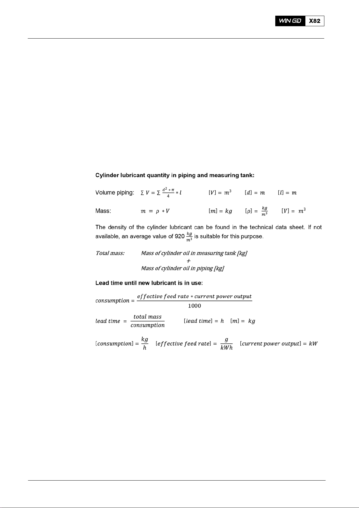
Operation0270−1/A1
Change-over from Heavy Fuel Oil to Marine Diesel Oil and Back
5. Cylinder Lubricating Oil
When you do a manual or automatic change−over of the fuel, you must make sure
that you change to the correct cylinder lubricating oil at the same time. This prevents
damage of the piston running system because of an incorrect BN. For more data refer
to 0750−1, Lubricating oils.
WinGD recommends to monitor the change−over of the cylinder lubricating oil. Do a
calculation of the cylinder lubricant quantity and make sure that you know cylinder
lubricating feed rate.
1) Make sure that you know the cylinder lubricant quantity that is between the
change−over valve and the lubricating quills including the measurement tube.
2) Calculate the related lead time that the cylinder lubricating oil has to get to the
lubricating quills.
2017−08
3) Use this lead time to have the correct timing for the change−over of the cylinder
lubricating oil.
Note: When you change from MDO to HFO, WinGD recommends to start the
change−over of the cylinder lubricating oil from low BN to high BN
already inside the ECA zone. This prevents operation with high sulphur
fuel and low BN cylinder lubricating oil.
2/ 4
Winterthur Gas & Diesel Ltd.
Page 89

Operation
Change-over from Heavy Fuel Oil to Marine Diesel Oil and Back
6. Change-over from HFO to MDO
See 0720−1 Fuel Treatment and Fuel System, Fig. 1.
To change−over from HFO to MDO, do as follows:
1) Make a full time schedule for the change−over to obey the ECA rules.
2) If you operate the engine with MDO for a long period, you must change the
cylinder lubricating oil to the applicable BN at the related time, refer to paragraph
5.
3) Set to OFF the trace heating of the fuel pipes and fuel rail approximately one
hour before the change−over. The correct time is related to the pipe diameter and
the waste heat in the system.
4) Set the viscosimeter to 17 cSt to decrease the temperature of the fuel.
5) Set to OFF all heating sources in the system (e.g. fuel heaters) some minutes
before the change−over.
6) Decrease the load of the engine to max. 50% CMCR. The decrease of the engine
power is related to the total quantity of fuel that flows in the system, e.g. the
larger the mixing tank, the less decrease in load is necessary.
0270−1/A1
7) Follow the instructions of the plant to slowly change−over the fuel supply from
HFO to MDO. Make sure that you decrease the fuel temperature a maximum of
2_C each minute.
8) If the temperature changes too much, wait until the fuel temperature is stable.
Then you can continue the procedure. Try to decrease the temperature as
linearly as possible.
9) When the temperature of the fuel is near the applicable value, you can start the
cooler slowly to give a linear and smooth temperature change at minimum
viscosity.
10) Do a check of the temperature, viscosity and pressure of the supplied fuel.
11) If the temperature, viscosity, or pressure is not correct, find the cause and repair
the fault.
12) If you have to collect the MDO from the leakage and return pipes, do as follows:
a) Wait until the system is completely flushed with MDO.
Note: This prevents contamination of the MDO with HFO.
b) If also a MDO leakage tank is installed, move the 3−way valve in the pipe from
the outlet of the fuel leakage fuel pump and injection control to the MDO leakage
tank.
c) If the fuel return of the pressure control valve goes into the HFO service tank, set
the valve positions to have the fuel return go into the MDO service tank.
Winterthur Gas & Diesel Ltd.
13) If you have to stop the engine, wait until the change−over procedure is fully
completed.
Note: This prevents problems during the subsequent engine start because of a
mixture of HFO and MDO in the system.
3/ 4
2017−08
Page 90

Operation0270−1/A1
Change-over from Heavy Fuel Oil to Marine Diesel Oil and Back
7. Change-over from MDO to HFO
See 0720−1 Fuel Treatment and Fuel System, Fig. 1.
To change−over from MDO to HFO, do as follows:
1) Make a full time schedule for the change−over to obey the ECA rules.
2) Make sure that you have changed the cylinder lubricating oil to the applicable
BN, refer to paragraph 5.
3) Set to ON the trace heating of the fuel pipes and fuel rail.
4) If the engine room is cold, after a minimum of one hour make sure to get correct
heating.
5) Make sure that HFO cannot flow into the MDO system.
a) If also a MDO leakage tank is installed, move the 3−way valve in the pipe from
the outlet of the fuel leakage fuel pump and injection control to the HFO leakage
tank.
b) If the fuel return of the pressure control valve goes into the MDO service tank,
set the valve positions to have the fuel return go into the HFO service tank.
6) Close all covers on the rail unit.
7) Decrease the load of the engine to max. 75% CMCR. The decrease of the engine
power is related to the total quantity of fuel that flows in the system, e.g. the
larger the mixing tank, the less decrease in load is necessary.
8) Set the viscosimeter to 13 cSt to increase the temperature of the fuel.
The viscosimeter controls the end-heater, which keeps the fuel temperature at the
necessary viscosity.
9) Follow the instructions of the plant to slowly change−over the fuel supply from
MDO to HFO. Make sure that you increase the fuel temperature a maximum of
2_C each minute.
Note: Sudden temperature changes can stop the movement of the fuel pump
plungers.
10) If the temperature changes too much, wait until the fuel temperature is stable.
Then you can continue the procedure.
11) Do a check of the temperature, viscosity and pressure of the supplied fuel.
12) If the temperature, viscosity, or pressure is not correct, find the cause and repair
the fault.
13) Keep the engine in operation until the change−over procedure is fully completed.
Note: This prevents problems during the subsequent engine start because of a
mixture of HFO and MDO in the system.
2017−08
4/ 4
Winterthur Gas & Diesel Ltd.
Page 91

Operation
Operation
Operation at Low Load
1. General
See the data that follow:
D 0240−1 Usual Operation, paragraph 2 Checks and Precautions
D Trace heating of the fuel system during operation
D Temperature of the cooling medium in the usual range (see 0250−1 Operating
Data Sheet)
D Careful treatment of the fuel (see 0720−1, Fuel Treatment and Fuel System)
D 0750−1 Operating Media, paragraph 3 Cylinder Lubricating Oil.
The cylinder lubricating oil quantity automatically adapts to the lower engine load. The
WECS−9520 controls the lubricating oil quantities related to the engine load.
2. WECS−9520 Injection Control
0280−1/A1
At low load the WECS−9520 automatically cuts out one of the three injection valves in
each cylinder. At very low load, two of the three injection valves are cut out.
This makes sure that the engine has the best fuel mist and combustion properties,
which decreases smoke from the funnel and fuel consumption.
The WECS−9520 changes the cutting out of the three injection valves at regular
intervals to get an equal thermal load in the combustion chamber.
There is no time limit to operate the engine at low load.
Winterthur Gas & Diesel Ltd.
1/ 1
2014
Page 92

Intentionally blank
Page 93

Operation
Operation
Operation at Overload
1. General
Usually, the engine is only operated at overload (110% of CMCR power) during sea
trials when there is an authorized representative of the engine builder on board the
ship.
The limit for operation of the engine at overload is a maximum of one hour each day
(see also 0070−1 The Relation between Engine and Propeller).
During operation at overload, you must carefully monitor the engine. If there are
unusual indications, you must decrease the load (power).
The load indication (fuel injection quantity) and the exhaust gas temperature
upstream of the turbine show the engine load (see 0250−1 Operating Data Sheet,
and the Acceptance Records).
The coolant temperatures must stay in their usual ranges.
In usual service, the full load position of the load indication (fuel injection quantity)
must stay in the limits given (see the Acceptance Records).
0290−1/A1
The maximum permitted position of the load indication (fuel injection quantity) is given
in the Acceptance Records. The adjustments are only permitted to show the CMCR
power during sea trials with an overspeed of 104% to 108% of CMCR power.
The conditions given below affect the speed of the ship:
D Sailing into strong head winds
D Sailing in heavy seas
D Sailing in shallow water
D When there is unwanted heavy growth on the hull.
The governor increases the fuel quantity to keep the speed of the ship constant. The
position shown on the load indication (fuel injection quantity) will increase.
Winterthur Gas & Diesel Ltd.
1/ 1
2014
Page 94

Intentionally blank
Page 95
Engine Shutdown
General
1. Engine Load Decrease
2. Engine Stop
2.1 Usual Procedures
2.1.1 Engine Stop from the Control Room − Remote Control
Operation
When possible, it is recommended that the engine load is decreased slowly, see
0260−1 Maneuvering.
Because different types of remote control can be connected to the engine controls,
the operation procedure from the manoeuvring stand in the control room is not given.
For this procedure, see the applicable documentation of the remote control
manufacturer.
Usually it is sufficient to move the telegraph to the position STOP.
0310−1/A1
2.1.2 Engine Stop from the Control Room − ECR Manual Control Panel
When you push the STOP button on the WECS−9520 manual control panel in the
ECR, the WECS−9520 decreases the engine speed/power, then shuts down the
engine.
2.1.3 Engine Stop from the Local Control Panel
See the Control Diagram 4003−2 and Local Control Panel 4618−1.
When you push the STOP button on the WECS−9520 manual control panel the
WECS−9520 decreases the engine speed/power, then shuts down the engine.
Note: You can use the buttons and rotary button only at the related active
control stand.
2.2 Emergency Stop
To stop the engine immediately, push the EMERGENCY STOP button in the control
room, or on the local control panel. The fuel pressure control valve 3.06 releases the
pressure in the fuel rail. At the same time, the fuel pump actuators move the
regulating linkages to the zero position.
2.3 Last Option
CAUTION
Damage Hazard. Do this emergency procedure only as a last
option. Damage to the engine can occur.
Winterthur Gas & Diesel Ltd.
You can also stop the engine as follows:
D In the supply box E85, set to off the electrical power to the WECS−9520.
1/ 1
2014
Page 96

Intentionally blank
Page 97

Engine Shutdown
Procedures after Engine Stop
1. Procedures for Short Service Breaks (some days to
1.1 Engine is Maneuverable
Operation
0320−1/A1
some weeks)
If the engine must still be maneuvered after it has stopped, see the conditions that
follow:
D The WECS−9520 must stay set to on.
D All the pumps for coolant water, lubricating oil and fuel must operate.
D Control air must be available and the starting air bottles must be full.
D The cylinder cooling water must be kept at the correct temperature.
D Do not cool the lubricating oil.
D The fuel must be kept at the applicable temperature in accordance with the
0710−1 Viscosity-Temperature Diagram.
Note: Post-lubrication of the cylinders starts automatically during the decrease
of engine speed (below 8%).
1.2 Engine is Not Maneuverable
If the engine is not maneuverable, see the conditions that follow:
D After the engine has stopped, the coolant water and lubricating oil pumps must
operate for a minimum of 20 minutes to let the temperatures become stable. Do
not let these media cool below their usual inlet temperatures. The sea-water
pump can, thus, usually be stopped immediately.
D If the engine was shut down during operation with HFO, then the supply must
flow through the fuel pumps and the fuel rail. The fuel system must continue to
operate.
D The fuel pipe heating system of the engine must be set to on. If this is not
necessary, change the engine operation to diesel oil before shut-down (see
0270−1 Change-over from heavy fuel oil to diesel oil and 0620−1 Procedures
before Putting Out of Service for a Long Period).
D The low pressure feed pump and booster pump can be stopped, if the engine
was shut down during operation with diesel oil (see 0720−1 Fuel Treatment and
Fuel Oil System).
D Where possible, keep the cooling water warm to prevent the engine from cooling
down too much. The cooling water pump thus, continues to operate unless it is
necessary to stop the pump for maintenance.
Winterthur Gas & Diesel Ltd.
1/ 3
2014
Page 98

Procedures after Engine Stop
Do the steps that follow:
1) Open the indicator valves in the cylinder covers.
2) Engage the turning gear.
3) Set the WECS−9520 to on.
4) At frequent intervals and with the indicator valves open, use the turning gear to
turn the engine as necessary (possibly done daily in damp climates). Do this
procedure while the lubricating oil pump and servo oil service pump operate and
set to on the cylinder lubrication at the same time. After this procedure is
completed, make sure that the piston stops in a different position each time.
5) Close the shut-off valve on the control air supply (supply of air from the board
system).
Note: Make sure that the lubricating oil pump is set to off before you bleed the
Note: Make sure that you know the safety precautions before you do repair
Operation0320−1/A1
air spring system.
work or overhauls (see the Maintenance Manual 0011−1 and 0012−1). If
necessary, release the pressure from the fuel oil system.
6) Repair all the defects found in service (leaks, etc).
1.2.1 Starting Air Manifold Venting / Stop the Starting Air System
Because of low air pressure after engine stop, the venting of the starting air
manifold (6, Fig. 1) cannot be done correctly. Thus, dirt and grease stay in the starting
air manifold and can cause the piston rings of the starting air valve (7) to stick.
Use high-pressure air at regular periods, to make sure that all dirt and grease is
removed from the starting air manifold.
Do the steps that follow:
1) Engage the turning gear.
2) Open the drain and test valve (3) momentarily. If you can hear the starting air
flow into the shut-off valve (1), close the drain and test valve (3). The starting air
manifold (6) is pressurized with high-pressure starting air.
3) Close the shut-off valves of the starting air bottles.
Note: You can usually find the venting valve (5) installed at the free end of the
starting air manifold. But on some engines the venting valve is installed
at the driving end. It is possible that two venting valves are installed on
different engine types.
4) Open the venting valve (5). The high-pressure air is released. Dirt and grease in
the starting air manifold are removed.
2014
5) Lift the lever then turn the handwheel (2) to position CLOSED.
6) Open the venting valve (4) to drain the shut-off valve (1).
2/ 3
Winterthur Gas & Diesel Ltd.
Page 99
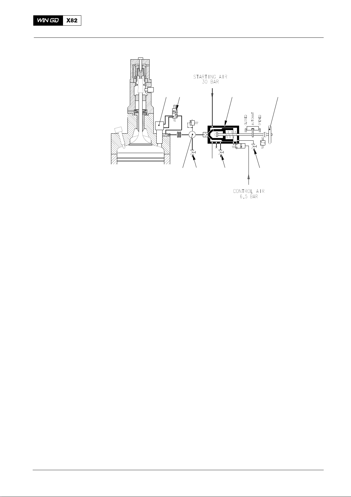
Procedures after Engine Stop
Operation
8
712
0320−1/A1
WCH01073
Fig. 1: Starting Air System
1 Shut-off valve for starting air 5 Venting valve 2.27
2 Handwheel for shut-off valve 6 Starting air manifold
3 Drain and test valve 2.06 7 Starting air valve
4 Venting valve 2.21 8 5/2-way solenoid valve
5
6
4
3
2. Procedures for Service Breaks for a Longer Period
(weeks or months)
Refer to paragraph 1.2 and to 0620−1 Procedures before Putting Out of Service for a
Long Period.
Winterthur Gas & Diesel Ltd.
3/ 3
2014
Page 100

Intentionally blank
 Loading...