


Installation Manual
Automatic Multi-Satellite
TV Antenna
Model SK-3005
DIRECTV® Slimline
www.winegard.com
For Technical Services, call 1-800-788-4417.
For Receivers and Programming, call 1-866-609-9374.
DO NOT RETURN ANTENNA TO PLACE OF PURCHASE.
For up-to-date information on receiver compatibility and programming, visit www.winegard.com/receivers
Product Registration
Please register your Winegard product by filling out and returning the Product Registration Card provided or by completing the online registration form at http://www.winegard.com/registration.
2452237
Congratulations! You have selected the Winegard® TRAV’LER® Automatic Multi-Satellite TV Antenna. The TRAV’LER antenna will deliver the ability to view up to five satellites at the same time with unmatched signal strength, the lowest travel height on the market, maximum HD capabilities and easy to use functionality—just like you get at home.This manual provides important information on the installation and operation of your TRAV’LER antenna. Please take time to read the manual in its entirety before installing or operating your antenna.
Table of Contents |
|
Installation |
|
Specifications.............................................................................................. |
1 |
Safety Recommendations.......................................................................... |
1 |
Clearance Requirements............................................................................ |
2 |
Parts............................................................................................................. |
2 |
Choosing a Location for the TRAV’LER Antenna...................................... |
3 |
Choosing a Location for Cables to Enter the Vehicle................................ |
3 |
Installing the TRAV’LER Antenna............................................................... |
4 |
Installing the Cable Entry Plate.................................................................. |
5 |
Installing the Cables................................................................................... |
5 |
Overall Installation...................................................................................... |
5 |
Installing the Reflector................................................................................ |
6 |
Winegard Mobile Products Limited Warranty........................................... |
6 |
Operation |
|
Automatic Operation.................................................................................. |
1 |
ManualOperation....................................................................................... |
2 |
DIRECTV Receiver Setup........................................................................... |
3 |
Ready to Travel?......................................................................................... |
4 |
Emergency Manual Stow........................................................................... |
4 |
Emergency Power Off................................................................................ |
5 |
Other Notes................................................................................................ |
5 |
Receivers Compatible with SWM Technology.......................................... |
5 |
Troubleshooting........................................................................................ |
6 |
Specifications
Height (stowed): 9.62 in |
Width (stowed): 33 in |
Length (stowed): 44 in |
Unit Weight: 53 lbs |
Shipping Weight: 74 lbs |
|
Depending on location and receiver type, the following satellites can be accessed with the SK-3005 in Multi-sat mode:
99°, 101°, 103°, 110°, 119°.
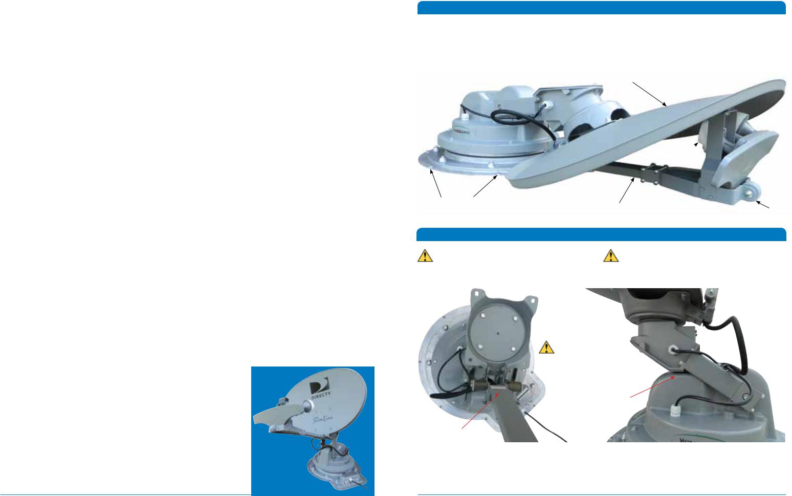
Reflector
LNB 
Screw Hole |
Arm |
|
|
|
Roller |
Safety Recommendations |
|
Do not attempt to install this system in the rain |
Do not paint this antenna. Painting the TRAV’LER |
|
or under any wet conditions. Moisture may affect |
antenna will void your warranty. |
|
electronics and void your warranty. |
|
|
Figure 1 |
|
|
Top View |
Side View |
|
Pay attention to the pinch points as the antenna raises. See Figure 1.
Pinch Point
Pinch Point
Disclaimer: Although every effort has been made to ensure that the information in this manual is correct and complete, no company shall be held liable for any errors or omissions in this manual. All information contained in this manual is subject to change without notice. No warranty of any kind is made with regard to the information included in this manual. The satellite interface is designed specifically for use with motorized recreational vehicles, and information contained herein is provided for that purpose only.
Installation |
1 |

roo f to h gi h
omfr
The arm of the TRAV’LER antenna extends 33” from the center of the base and may operate only 10” above the” 5.7 surface to which the TRAV’LER antenna is mounted. To ensure you have adequate clearance for the TRAV’LER3
antenna to safely operate, check that there are no obstructions taller than 10” within 33” of the center of the base.
Also, check that there are no obstructions (such as tree limbs) above the antenna that will prevent it from raising. At its highest point, the antenna will extend to 37.5” above the roof to which it is mounted. See Figure 2.
Figure 2
roof to arm |
33” from end of arm to center of base |
|
10” from |
||
|
||
|
|
Parts
Mount Base with 30’ Power/Control Cable |
TRAV’LER Power Supply |
TRAV’LER Interface Box |
Mounting Screw (20)
Cable Entry Plate
Reflector
5/16” Reflector Nut (4)
24” AC power cord |
30’ Gray Coax Cable |
30’ Black Coax Cable |
|
5/16” Reflector Bolt (4)
2 |
Installation |
Choosing a Location for the TRAV’LER Antenna
For best performance and to reduce signal acquisition time, park the vehicle on a level surface that is free of obstructions such as trees or large buildings. Make sure you have a clear view of the southern sky.
Before removing the TRAV’LER antenna from its box, contact your RV dealer or manufacturer. Your RV may be pre-wired or have a reinforced area for this system.
Choose a location on the roof of the RV that meets the following requirements:
Figure 3
Top View
Center of Base
|
|
|
|
|
|
|
ot Y |
|
|
|
|
|
|
|
|
|
|
N |
e |
|
|
||
|
|
|
|
|
( |
|
|
t |
A |
|
|
|
|
|
|
r |
|
|
|
|
|
||
|
|
|
o |
|
|
|
|
|
t |
||
|
|
|
t |
|
|
|
|
|
|
|
t |
|
|
c |
|
|
|
|
|
|
|
a |
|
|
|
le |
|
|
|
|
|
|
|
|
h |
|
f |
|
|
|
|
|
|
|
|
c |
|
|
|
|
|
|
|
|
|
|
e |
||
R |
e |
|
|
|
|
|
|
|
|
|
d |
|
|
|
|
|
|
|
|
|
|
) |
|
|
|
|
|
|
|
|
|
|
|
|
|
|
|
|
|
|
|
|
|
|
|
e |
d |
) |
R |
|
|
|
|
|
|
|
|
h |
|
||
|
|
|
|
|
|
|
|
|
|
|||
e |
|
|
|
|
|
|
|
|
|
|
|
|
f |
|
|
|
|
|
|
|
c |
|
|
|
|
l |
|
|
|
|
|
|
a |
|
|
|
|
|
e |
|
|
|
|
|
t |
|
|
|
|
||
c |
|
|
|
|
t |
|
|
|
|
|
||
|
|
|
A |
|
|
|
|
|
|
|||
|
t |
|
|
|
|
|
|
|
|
|
||
|
o |
|
t |
|
|
|
|
|
|
|
||
|
|
r |
e |
|
|
|
|
|
|
|
|
|
|
|
|
(NotY |
|
|
|
|
|
|
|
|
|
1Offers enough support for a secure installation
2Allows dish to raise and rotate without interference from other roof-mounted equipment
3Has a minimum roof space of 44” x 33” for antenna (Figure 3)
4Lacks obstructions taller than 9” mounted within a
33” |
33” radius from the center of the TRAV’LER base |
5Has a gap of less than 3/16” between the bottom of the antenna and the roof
(Do not install the TRAV’LER antenna in a location where a gap of 3/16” or more exists between the bottom of the antenna and the roof, as the antenna may damage the roof)
|
|
6 Is within 5 degrees of level, or the system may |
44” |
||
Winegard is NOT liable for damage, expenses, or |
require more time to locate satellites (for best |
|
injury caused by improper installation. |
operation, must be within 3 degrees of level) |
|
Choosing a Location for Cables to Enter the Vehicle
Once you have chosen a location for the TRAV’LER antenna, choose a location for the cables to enter the vehicle. Keep in mind the following:
1 The TRAV’LER interface box must plug into a |
Figure 4 |
well-ventilated 110 V outlet. |
|
2The 24” AC power cord must be long enough to extend from the outlet to the TRAV’LER power supply, which will then connect to the TRAV’LER interface box.
3The 30’ control cable must be long enough to extend from the TRAV’LER mount base to the interface box.
4One 30’ coax cable will need to be run from the mount base to each receiver inside the vehicle.
Note: the provided coax cables only include a connector on one end.
24” |
18” |
Do not run wires through the striped area shown in Figure 4. Anything in the striped area will interfere with the operation of the TRAV’LER antenna and may cause damage to the object or to the TRAV’LER antenna.
Make sure cables are long enough to reach their destination points inside the vehicle.
For cable runs longer than 30’, an extension may be purchased. Winegard recommends using the CL-SK26 25’ extension cable. Do not exceed 55’ of cable!
Installation
CL-SK26
Sold Separately
3
 Loading...