

Page 1
WINEGARD
®
RoadTrip
™
Digital Satellite Mobile Antenna for Two Receivers
RoadTrip SD - Stationary Satellite System
TM
TM
RoadTrip SDi - In-Motion Satellite System
INSTALLATION MANUAL
Made in the U.S.A.
Winegard Company • 3000 Kirkwood St. • Burlington, IA 52601-2000
319/754-0600 • FAX 319/754-0787 • www.winegard.com
Printed in U.S.A. © Winegard Company, 2006 2452086
1
Page 2
Parts Included • Tools Needed • How to Unpack
The Winegard RoadTrip is designed specifically for use with motorized recreational
vehicles. Winegard recommends using a qualified installer familiar with RV structure and
wiring to ensure proper installation and to prevent damage to RV or dish.
PARTS INCLUDED:
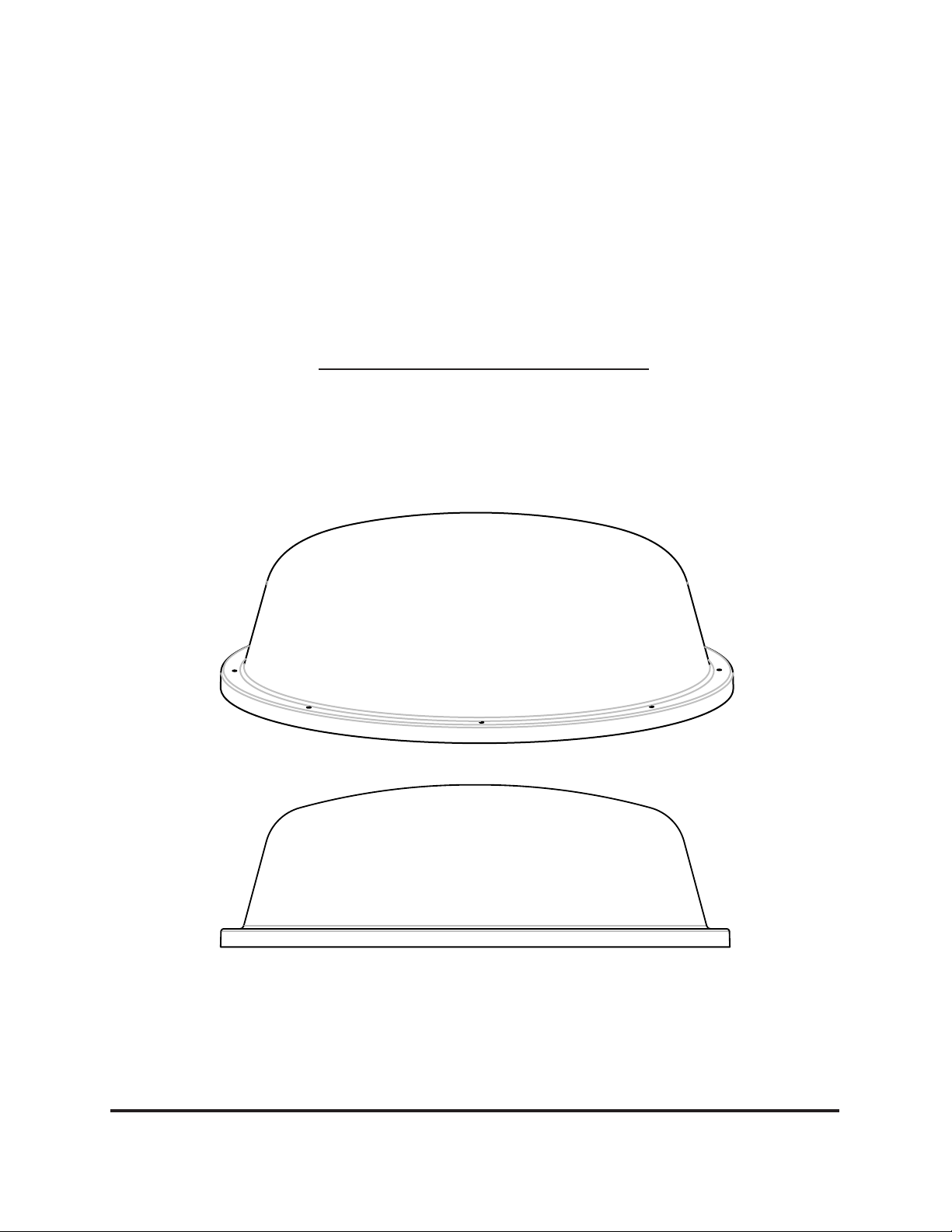
1 Radome
1 Cable entry plate
All required screws, washers, bolts, and nylocks
1 base with electronics, dish, dual LNBF,
mounting feet
TOOLS NEEDED FOR UNPACKING & INSTALLATION:
Level
Drill w/3/4” bit
1-1/4” hole saw (if mounting switch in wall)
Phillips screw driver #2
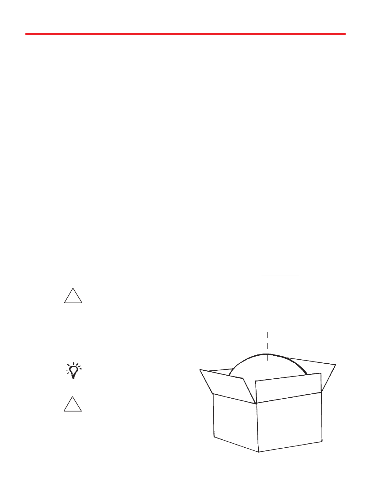
UNPACKING THE UNIT
1. Open box and remove packing material.
If using knife to open
!
carton, BE CAREFUL.
Do not cut the dome on
the unit.
4’ Gray Coax Cable (OEM Model)
4’ White Coax Cable (OEM Model)
4’ Power Cable (OEM Model)
3/8” Open end wrench
7/16” Open end wrench
Sealant (consult RV manufacturer for proper type
for your roof material)
LIFT UNIT STRAIGHT UP
OUT OF CARTON!
2. Lift dome out of box vertically. Then lift unit out of
box vertically. Do not turn box and “roll” out, or turn
upside down to remove.
USE 2 PEOPLE
when removing the unit
from the carton.
DO NOT PAINT DOME!
!
Painting dome will
cause signal
degradation and will
void your warranty.
REV. 12/05
2
Page 3
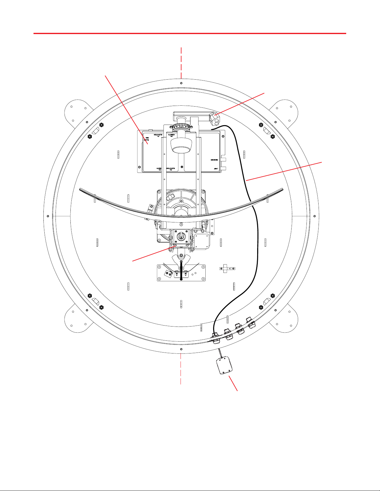
Control Unit
Installation Diagram
LNBF
GPS CABLE
(RoadTrip SDi
ONLY)
ELEVATION
MOTOR
CONTROL UNIT MUST
BE PARALLEL TO THE
CENTER LINE OF THE
VEHICLE AND FACE
FRONT OR REAR OF
VEHICLE.
CENTER
LINE OF THE
VEHICLE
GPS ANTENNA
(RoadTrip SDi ONLY)
3
Page 4

Quick Reference Guide
Your Winegard RoadTrip satellite System has been designed to be the most user-friendly
Mobile Satellite Antenna on the market today. Upon installation of the antenna, or after
changing satellite service provider, simply set the switches inside of the dome to the settings
shown in the Operation manual. These switches enable the dish to locate the proper satellite
for your service provider, and, for the RoadTrip SDi In-Motion system, to be set for the proper
installation option. Simply set the switch, and forget it! Your Winegard RoadTrip Satellite
Antenna will locate the proper satellite with just the flip of a switch.
Mounting Instructions
It is essential to mount your RoadTrip Automatic System in the proper position and orientation
on your RV roof to ensure proper operation. Choose a location on your roof clear of
obstruction and close to your receiver and power source.
™
To ensure proper tracking with your RoadTrip SDi, you must mount the unit so that the unit is
TM
centered on the centerline and cables exit either towards the front or back of the RV. See
Figure 1c below.
FIGURE 1C
MOUNTING OPTION A
FRONT OF VEHICLE
CENTER LINE OF VEHICLE
MV-3500
ROADTRIP
CABLE EXIT REAR
MOUNTING OPTION B
FRONT OF VEHICLE
CENTER LINE OF VEHICLE
CABLE EXIT FRONT
BACK OF VEHICLE
MV-3500
ROADTRIP
Switch Settings
After mounting the RoadTrip System to your rooftop, you must set the RoadTrip’s switch
settings for the mountoing options chosen and satellite Television Service Provider. The chart
below lists switch settings for both the RoadTrip SD and RoadTrip SDi. See page 3. of
TM
TM
Operation Manual for detailed instructions.
RoadTrip SD
TM
BACK OF VEHICLE
1 2 3 4 5 6 7 8
0 = UP
0 0 0 0 0 0 0 1
RoadTrip SDi
1 2 3 4 5 6 7 8
0 = UP
0 0 0 0 0 0 0 1
TM
1 = DOWN
1 = DOWN
(#1 represents Switch DOWN; #0 represents Switch up)
Sat. Rcvr. Mt. Option Switch Set Position
................................... 1 2 3 4 5 6 7 8
DIRECTV A 0 0 0 0 0 0 0 1
(FACTORY PRESET)
DISH NETWORK A 0 0 0 1 0 0 1 1
0= UP 1= DOWN
(#1 represents Switch DOWN; #0 represents Switch up)
Sat. Rcvr. Mt. Option Switch Set Position
..................................... 1 2 3 4 5 6 7 8
DIRECTV A 0 0 0 0 0 0 0 1
(FACTORY PRESET)
DIRECTV B 1 0 0 0 0 0 0 1
DISH NETWORK A 0 0 0 1 0 0 1 1
DISH NETWORK B 1 0 0 1 0 0 1 1
0= UP 1= DOWN
4
SWITCH SETTINGS
SHOWN
SWITCH SETTINGS
SHOWN
Page 5

Installing unit on roof of vehicle —
Installation
Install in DRY conditions only!
!
IMPORTANT! Do not install this system
in the rain, or under any wet conditions. Mois-
ture may affect electronics and void your
warranty!
1. For best performance and to reduce signal acquisition time, park vehicle on a level surface;
level the RV.
2. Select a level spot on your roof for installation.
Using the chart,
determine the
minimum distances
to other equipment.
FIGURE 3
OBSTRUCTION
Obstruction Ht. Unit Clearance
8” ...................................... 2”
10” .................................... 8”
12” .................................. 13”
15” .................................. 22”
UNIT BASE
5. Place the unit on the roof in its permanent loca-
tion and mark around each base foot, Figure 4.
FIGURE 4
6. Clean roof area where the base feet will be
attached to the roof. Do not erase your marks!
7. Put approved sealant in the areas marked
for the base feet. Place base feet on top of the
sealant and screw down with the (3) #10
screws for each foot.
WARNING: Level the base front to back and side
to side. If base is not level the RoadTrip may require more time to locate the correct satellite or
may not locate the correct satellite.
• Be sure no roof-mounted equipment is
blocking the satellite “line of sight”, Fig. 3
3. After selecting location for unit (see number 2),
put the unit on the centerline of the vehicle.
4. Position base so that cables exit either toward
the rear (Mounting Option A) or toward the front
(Mounting Option B) of vehicle.
Electronics box
MUST be parallel to the center
line of the vehicle. See page 4.
8. After all base feet are secured to roof, put
sealant around edge of feet and over screws.
FIGURE 5, Mounting Option A shown
Front of Vehicle
A’ B’
Center Line
ROADTRIP
The distance from the edge of the roof to the
rear corner of the foot should be equal on both
sides of the dish to ensure proper installation.
5
Page 6

Installation
GPS installation — (RoadTrip SDi only)
10. The GPS antenna is pre-wired and has a 1 meter
cable running through one of the connectors.
Determine location for GPS antenna. It is recommended you place the GPS antenna 3 feet from
dome and away from any other obstruction.
The recommended location for the GPS antenna is
based on having a level location and a clear view of
the sky for the best satellite signal acquisition. Do not
secure GPS antenna to roof at this time.
IMPORTANT! The GPS must be located minimum of
3 feet away from obstructions on roof of vehicle. An-
tenna must have a clear view of the sky for proper
operation.
NICKS OR CUTS IN WIRING JACKET MAY
CAUSE WATER TO LEAK INTO VEHICLE.
!
Cable entry installation —
1. Connect coax cables and power wire to RV prewire harness. Connect gray coax to pre-wire coax for
primary receiver. Connect white coax to pre-wire coax
for secondary receiver. Connect power cable to prewire power cable. See Figure 2.
2. Place cable-entry plate over hole and cables.
Screw in place. Seal plate and screw holes with approved sealant (not included).
FIGURE 2
COAX CABLE ROUTING
INSTALLING THE POWER SWITCH
1. Choose a location to install the RoadTrip power
ON/OFF switch. Remember when selecting a location
that you will need to run the +12VDC power cable
from the RoadTrip to the switch. Be sure the
switch is in the OFF position before continuing.
See Figure 7 page 9.
Wall or panel mount: Drill 1-1/4” hole, pull wires
through wall or panel.
2. Connect the ground wire from the vehicle and the
BLACK ground wire from the RoadTrip together,
using large yellow flag connector.
3. Connect the YELLOW flag connector to
the silver spade on the switch.
4. Connect the RED wire from the RoadTrip to the
small RED flag connector.
5. Connect small RED flag connector to center
spade on switch.
6. Connect the +12 V power wire from the vehicle to
a small RED flag connector.
7. Connect small RED flag connect to isolated
spade on switch.
INSTALLING THE POWER SWITCH DIAGRAM
FIGURE 7
ON/OFF ROCKER SWITCH
WITH LIGHT
(Shown in OFF position.)
MV-3500
ROADTRIP
PRIMARY
RECEIVER
(GRAY WIRE)
SECONDARY
RECEIVER
(WHITE WIRE)
STEPS 2 & 3
TWO GROUND WIRES
1 FROM VEHICLE
1 BLACK WIRE FROM
SATELLITE DISH
STEPS 6 &7
+12 V FROM VEHICLE
STEPS 4 & 5
RED POWER
WIRE FROM
DISH
6
Page 7

Installation • Wiring • Specifications
Connecting the receiver —
Connecting one receiver
1. Connect the coax cable from the gray coax
cable of the RoadTrip™ to the “SATELLITE IN” on
the receiver.
2. See page 5 of Operations Manual for receiver
set-up.
Connecting two receivers
1. Connect the gray coax cable coming from the
RoadTrip™ to the “SATELLITE IN” input on the
primary receiver. The primary receiver is the
receiver used most often and will toggle between
satellites.
2. Connect the white coax cable coming from the
RoadTrip™ to the “SATELLITE IN” input on the
secondary receiver. NOTE: Secondary receiver
will not toggle.
3. See page 5 of Operations Manual for receiver
set-up.
Your RoadTrip™ has now been successfully installed. Proceed to the Operation
Manual for RoadTrip™ setup and for Operation Instructions.
Features and specifications
• One button operation.
• Dual receiver capable.
• Depending on receiver type, you can access
satellites 119°, 110°, or 101°.
• No user input required.
• Elevation range 20° to 60°;
azimuth +360° (0-720°)
• Dome UV protected.
• Compact size —
32” diameter, 12-1/2” height
Shipping size - 37-1/4” x 34” x 14-3/4”
Shipping weight - 55 lbs.
• Operating temperature
-13°F to +140°F
• Specifications for max amperage 5.0A
• Specifications for unit operatating voltage. -10.5 - 13.8V
• Specifications for supply voltage. 12 - 13.8V
7
Page 8

Winegard Company • 3000 Kirkwood Street • Burlington, IA 52601 • 319/754-0600 Fax 319/754-0787 • www.winegard.com
Printed in U.S.A. © 2006, Winegard Company 2452086
8
 Loading...