

Page 1
WINEGARD
ROADSTAR
RV AND VAN TV ANTENNA
MODELS RS-2000 & RS-3460/RS3460B
Made in U.S.A.
INSTRUCTIONS
SPECIFICATIONS
Bandpass
VHF/FM .............................. 54 to 216 MHz
UHF .................................... 470 to 810 MHz
Amplifier Gain ......................
VHF* .................................. 15.5 dB avg.
UHF .................................... 19.5 dB avg.
Impedance ............................ 75 ohm unbalanced
Response .............................. .25 dB per 6 MHz
VSWR .................................... 1.8:1 max.
Power Required .................... +12 VDC at 85 ma
Weatherproof Housing ......... Weatherable
UV stabilized
copolymer
*Has fixed FM trap to reduce interference.
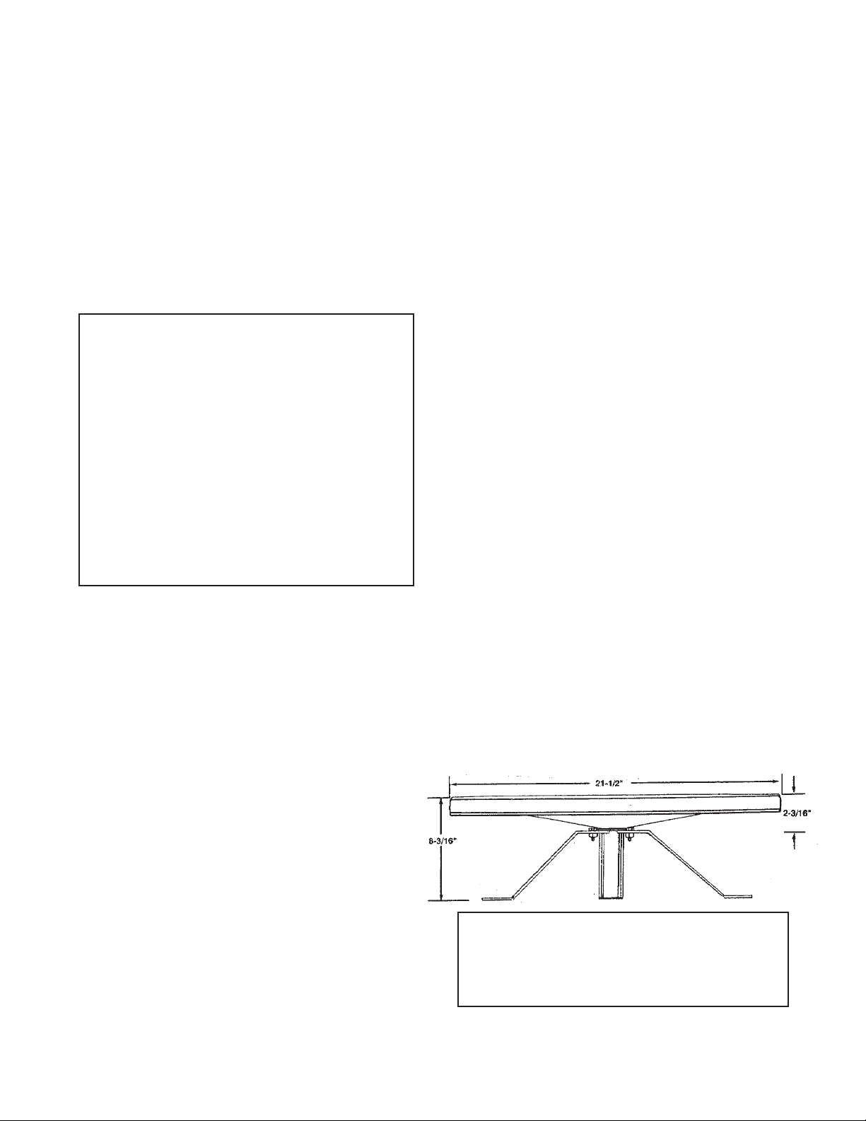
DESCRIPTION
Winegard's RoadStar
excellent reception of VHF/UHF TV channels. The
RoadStar compact modern styling is unobtrusive and
blends well with the designs of recreational vehicles. The
UV stabilized copolymer housing makes the antenna
virtually impervious to weathering and color change.
TM
omnidirectional antenna provides
®
TM
PARTS LIST (RS-2000) White Housing
1 Amplified Antenna 2120415
6 10-32 Hex Nut, Nylock 2160216
1 Power Supply with Hardware 2120123
1 30' Coaxial Cable 2753015
1 6' Coaxial Cable 2753752
3 Roof Mounting Brackets 3720303
6 #10 x 1" Thread Cutting Screws 2160178
1 Bolt, 1-14 x 1" Nylon 3200350
1 Mounting Plate 3710248
6 10-32 x 5/8" Bolt 2160173
6 Washer, #10 Aluminum 1140302
PARTS LIST (RS-3460) White Housing
(RS3460B) Black Housing
1 Amplified Antenna (white) 2120415
Amplified Antenna (black) 2120404
6 10-32 Hex Nut, Nylock 2160216
3 Roof Mounting Brackets 3720303
6 #10 x 1" Thread Cutting Screws 2160178
1 Bolt, 1-14 x 1" Nylon 3200350
1 Mounting Plate 3710248
1 Coaxial Cable B oot 3200154
6 10-32 x 5/8" Bolt 2160173
6 Washer, #10 Aluminum 1140302
The unique omnidirectional characteristics provide excellent reception in areas where stations are in different
directions without the need for a complex rotor system.
A built-in amplifier provides up to 6 times the received
signal on VHF and 9 times the UHF signal insuring the
best possible reception in color and black and white.
The RS-2000 package includes antenna, +12 VDC power
supply with two-way splitter, 30' downlead cable, 6' TV set
cord, hardware and mounting bracket.
Winegard Company
3000 Kirkwood St., Burlington, IA 52601-2000
Printed in U.S.A. 2451806 © Winegard Company, 1998, 2004, 2006 Rev.3 10/10
CLEANING ANTENNA HOUSING
The surface of the antenna is a tough laminated
ultraviolet shield. Clean only with mild soap and
water. Use no solvents, alcohol, or cleaning
fluids.
Page 2
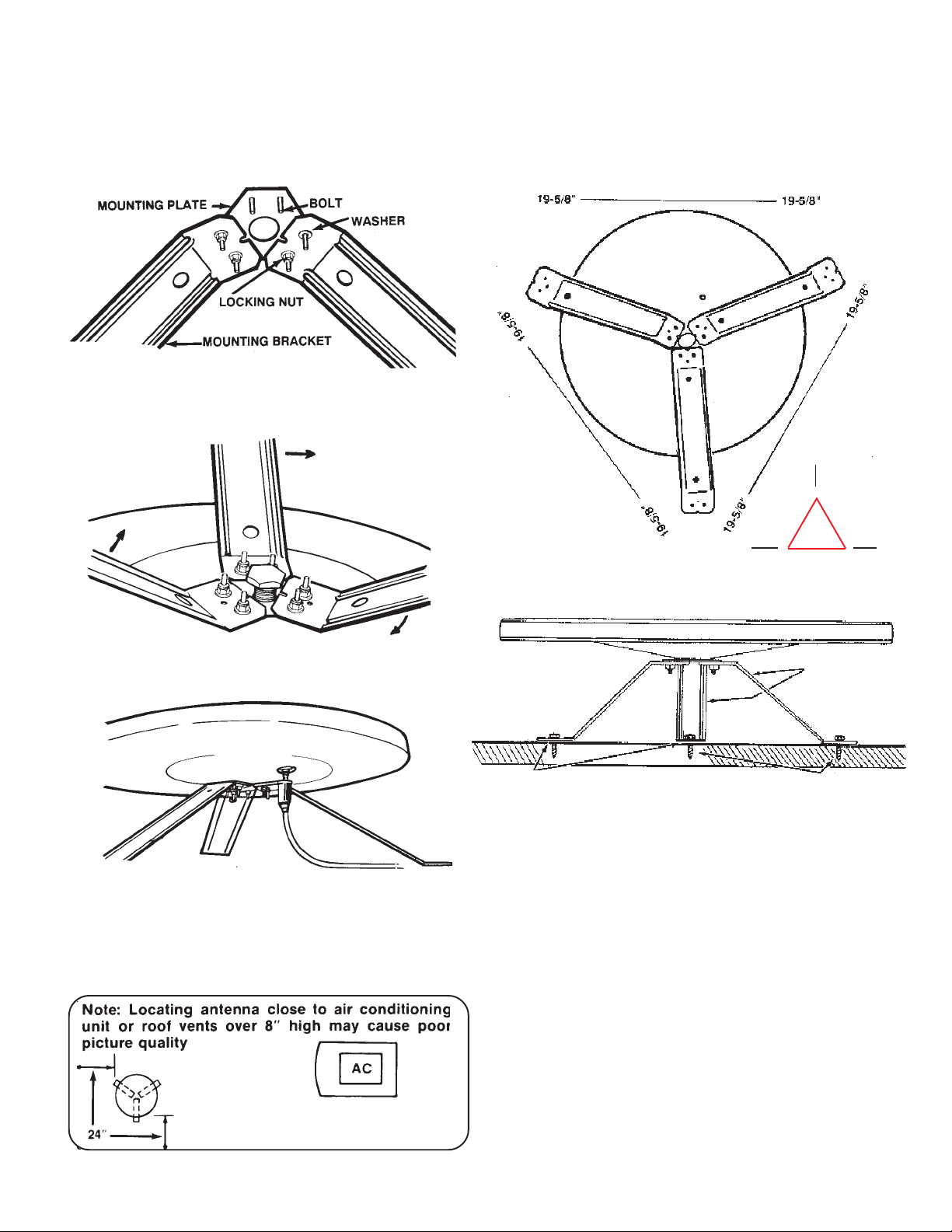
ANTENNA MOUNTING INSTRUCTIONS
STEP 1. Assemble mounting brackets onto mounting
plate. Insert 10-32 x 5/8" bolts through mounting plate
and mounting brackets. See Figure 1. Attach #10 x 9/16
x 1/6 washers and 10-32 locking nuts. Tighten securely.
FIGURE 1
STEP 2. Place assembled mount on bottom of antenna
housing and thread in 1" nylon bolt. Spin the assembled
mount to tighten securely.
NOTE: Holes for mounting brackets are at corners of
19-5/8" triangle. We recommend you make a template
from 19-5/8" triangular piece of cardboard. Try to
locate holes on roof rafters on other solid members
inside roof. See Figure 5.
FIGURE 2
STEP 3. Attach end of coaxial downlead cable with boot
to jack on bottom of antenna and slide boot up over boot
collar. See Figure 3.
FIGURE 3
STEP 4. Select location for antenna on roof of vehicle.
Try to position antenna about 24" from edge of vehicle
roof, convenient to downlead entry point and as far away
as possible from roof mounted equipment such as air
conditioners or roof vents. See Figure 4.
or no reception.
FIGURE 5
19-5/8"
19-5/8"
LOCATE HOLES OVER
RAFTERS OR OTHER
SUPPORTS IN ROOF
APPLY APPROVED NON-HARDENING
CAULKING COMPOUND UNDER
EACH BRACKET
#10 x 1" THREAD
CUTTING SCREWS
ROOF MOUNTING
BRACKETS
FIGURE 6
STEP 5. Drill six 1/8" pilot holes as shown in Figure 6.
Apply approved sealant for your type of roof around holes
under each bracket. Attach antenna to roof with #10 x 1"
thread cutting screws.
STEP 6. The power supply/wall outlet assembly may be
flush mounted in most standard electrical boxes. To flush
mount cut a hole in wall to fit the box. Run 2 #12 wires
between wall outlet and +12 VDC source and route
downlead cable to this location. Install cable between set
2 outlet and power supply SET 2 jack at this time.
See Figure 7.
19-5/8"
FIGURE 4
WARNING: DO NOT CONNECT +12 VDC SOURCE TO
POWER SUPPLY AT THIS TIME. POWER SUPPLY
MAY SHORT, IF +12 VDC SOURCE IS CONNECTED.
2
Page 3

STEP 7. Install connectors on downlead and set 2 cable
as shown on page 4. Attach antenna downlead cable to
jack on power supply marked “ANT”. See Figure 7.
FIGURE 7
STEP 8. Install terminals on wires from +12 VDC source
as shown in Fig. 8. Crimp terminals with Craftsman type
4 crimping tool in Fig. 9 or equivalent. Push wires onto
tabs on terminal board as shown in Figure 10. If in doubt
as to the polarity of the wires, connect them temporarily
to tabs on circuit board in Fig. 10 and move switch on front
of outlet to left, (in Fig. 11) if light comes on polarity is
correct.
FIGURE 8
FIGURE 9
FIGURE 10
FIGURE 11
STEP 9. Mount power supply in wall with screws pro-
vided and attach TV coax cable to jack on front. Connect
TV coax cable to TV set. Move switch on front of outlet
to the left and check that light is on.
at +12 VDC.
CHECKING POWER SUPPLY OPERATION
(Power Supply not supplied with RS-3460)
1. Tune TV receiver to nearest station.
2. Turn off switch on power supply.
Picture on TV receiver should be
considerably degraded with power off.
3. This unit is equipped with a
polyswitch, (current limiting device), which will shut down +12 VDC
if there is a direct short in the cable
between antenna and power supply.
Red indicator light will not light.
Once short is eliminated, device
will reset itself.
WINEGARD MOBILE PRODUCTS LIMITED WARRANTY
Winegard Company warrants this product against defects in materials or
workmanship for a period of two (2) years from the date of original purchase.
During year one (1) of such warranty, Winegard Company will also pay
authorized labor costs to an authorized Winegard dealer to repair or replace
defective products. No warranty claim will be honored unless at the time
the claim is made, Customer presents proof of purchase to an authorized
Winegard dealer (to locate the nearest authorized Winegard dealer, contact
Winegard Company, 3000 Kirkwood Street, Burlington, Iowa 52601,
Telephone 800-288-8094 or visit www.winegard.com). Customer must
provide proof of purchase with a dated sales receipt for the Winegard product
to verify the product is under warranty. If the date of purchase cannot be
verified, the warranty period shall be considered to begin thirty (30) days
after the date of manufacture.
If a defect in material or workmanship is discovered, Customer may take
the product to an authorized Winegard dealer for service. Customer must
provide proof of purchase to verify the product is under warranty. If the
product is brought to an authorized Winegard dealer for service prior to
expiration of year one (1) of the warranty period and a defect in material or
workmanship is verified by Winegard Technical Services, Winegard
Company will cover the Winegard dealer’s labor charges for warranty
service. The Winegard dealer must contact Winegard Technical Services
in advance for pre-approval of the service. Approval of the service is at
the sole discretion of Winegard Company.
Alternatively, Customer may ship the product prepaid to Winegard Technical
Services (located at 3111 Kirkwood Street, Burlington, Iowa 52601,
Telephone 800-788-4417). Customer must return the product along with a
brief description of the problem and provide Winegard Technical Services
with Customer’s name, address, and phone number. Customer must also
provide proof of purchase to verify the product is under warranty. If the
product is returned before the expiration of the warranty period, Winegard
Company will (at its option) either repair or replace the product.
This Limited Warranty does not apply if the product has been damaged,
deteriorates, malfunctions or fails from: improper installation, misuse,
abuse, neglect, accident, tampering, modification of the product as originally
manufactured by Winegard in any manner whatsoever, removing or
defacing any serial number, usage not in accordance with product
instructions or acts of nature such as damage caused by wind, lightning,
ice or corrosive environments such as salt spray and acid rain.
Warranty also does not apply if the product becomes unable to perform its’
intended function in any way as a result of the television signal provider
making any changes in technology or service.
A Return Material Authorization (RMA) is required prior to returning any
product to Winegard Company or Winegard Warranty Services under this
warranty policy. Please call our Technical Services Department at 800-7884417 or send an e-mail to warranty@winegard.com to obtain the RMA
number. Please furnish the date of purchase when requesting an RMA
number. Enclose the product in a prepaid package and write the RMA
number in large, clear letters on the outside of the package. To avoid
confusion or misunderstanding, a shipment(s) without an RMA number(s)
or an unauthorized return(s) will be refused and returned to Customer freight
collect.
WINEGARD COMPANY DOES NOT ASSUME ANY LIABILITIES FOR ANY
OTHER WARRANTIES, EXPRESS OR IMPLIED, MADE BY ANY OTHER
PERSON.
ALL OTHER WARRANTIES WHETHER EXPRESS, IMPLIED OR
STATUTORY INCLUDING WARRANTIES OF FITNESS FOR A
PARTICULAR PURPOSE AND MERCHANTABILITY ARE LIMITED TO
THE TWO YEAR PERIOD OF THIS WARRANTY.
In states that do not allow limitations on implied warranties, or the exclusion
of limitation of incidental or consequential damages, the above limitations
or exclusions do not apply.
Some states do not allow limitations on how long an implied warranty lasts,
or the exclusion of limitation of incidental or consequential damages, so the
above limitations or exclusions may not apply to you.
This warranty gives Customer specific legal rights. Customer may also
have other rights that may vary from state to state
3
(2 YEARS PARTS; 1 YEAR LABOR)
RETURN AUTHORIZATION POLICY
SATELLITE RECEIVER WARRANTY
See manufacturer’s limited warranty policy.
WS-MOBWARREV2 Rev. 1/10
POLYSWITCH
This Limited
Page 4

WHAT TO DO WHEN YOUR RV/TV ANTENNA IS NOT WORKING PROPERLY
INSTALLING COAX CABLE ON
FC- 5910 CONNECTORS
STEP 1: Strip outer cover back 1/2"* from end of cable. Fray braid back
as far as outer cover will allow.
STEP 2: Trim braid close to outer cover and remove 1/4"* of inner insulation
being careful not to nick center conductor. Make sure no foil or braid can
touch center conductor.
STEP 3: Slide connector tip between braid and inner insulation (braid and
foil, on foil shield cable) and push connector on cable as far as it will go.
Crimp built-in ferrule with appropriate crimping tool. Do Not crush cable
out-of-round. *If installing in very hot weather, increase these dimensions
1/8".
* If installing in very hot weather, increase these dimensions 1/8".
WARNING
DO NOT INSTALL COUPLERS, SPLITTERS, ETC.
BETWEEN THE POWER SUPPLY AND THE ANTENNA. INSTALLATION OF ANY ITEM ON THE DOWNLEAD MAY CAUSE A SHORT IN THE SYSTEM. THE
DOWNLEAD SUPPLIES +12 VDC TO THE PREAMP IN
THE ANTENNA.
HOW YOUR SYSTEM WORKS
Turning power supply on sends +12 VDC up cable to
antenna. Voltage energizes transistors on amplifier in
antenna head. TV signal comes back down cable to
outlets.
TO TEST SYTEM
1. Make sure TV set is working properly.
2. Switch power supply ON and OFF to see if there is a
difference in the picture quality while watching TV. If
there is NO difference, proceed to the next step.
CAUTION
The power supply should be turned OFF when connecting/disconnecting cables to power supply and
antenna, but should be turned ON when testing for
voltage.
3. Disconnect cable from antenna and check for +12
VDC at test point #1. If there is +12 VDC, the power
supply is OK and the antenna needs to be replaced.
4. If there is no +12 VDC at test point #1 reconnect the
cable to antenna. Remove power supply from wall and
visually inspect for burnt/broken parts. If there are any
broken or burnt parts replace power supply.
5. Disconnect cable from antenna jack on power supply.
Check for +12 VDC at test point #2. If there is +12 VDC
then there is a problem in the cable connecting the
power supply to the antenna. Repair/ replace cable.
HOW YOUR
SYSTEM WORKS
HOOKS INTO +12VDC BATTERY +
2ND SET
HOOK UP
GND -
SET 2
AMPLIFIED
TV SIGNAL
WHITE
RED
TEST POINT #1
+12VDC AT ANTENNA
+12VDC
ANTENNA
CONNECTION
+ Point center wire
- Point outside of
connector
TO TEST SYSTEM
GND
+ 12VDC
SET 2
2ND SET
NO +12VDC
AT THIS POINT
FIGURE 1 FIGURE 2 FIGURE 3 FIGURE 4
WHITE
RED
AT SET 2 JACK
REMOVE CABLE
FROM ANTENNA
ANTENNA
CONNECTION
TEST POINT #2
+12VDC AT
ANT. JACK
6. If +12 VDC is not present at test point #2, check that
the red indicator is ON. If not, check the polarity of the red/
white wires and check the +12 VDC source. If there is still
no +12 VDC replace the power supply.
RF CHOKE RF CHOKE POLYSWITCH POLYSWITCH
POWER SUPPLY
IN METAL HOUSING
POWER SUPPLY
NO POLYSWITCH
POWER SUPPLY
W/POLYSWITCH
POWER SUPPLY
W/POLYSWITCH
4
 Loading...