

Page 1
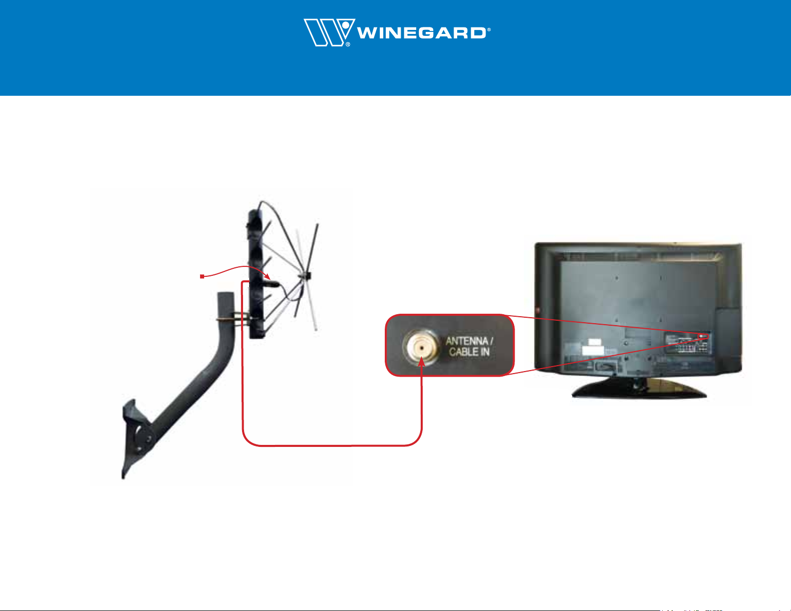
Wiring Diagram for FREEVISION® Antenna to Television
(Side View—mount not included with all models)
Note: the matching transformer
must be connected as described
on page 4 of the manual.
FREEVISION® Antenna
Back of TV
Antenna/Cable In
Coax Connection Port
Coax Cable
Winegard model AP-8700 preamplifier and model PS-1403 power inserter are shown above.
Winegard Company • 3000 Kirkwood St. • Burlington, IA 52601-2000 • 800-288-8094 • fax 800-247-8221 • www.winegard.com • Printed in U.S.A. ©2011 Winegard Company • WC-1051
Page 2
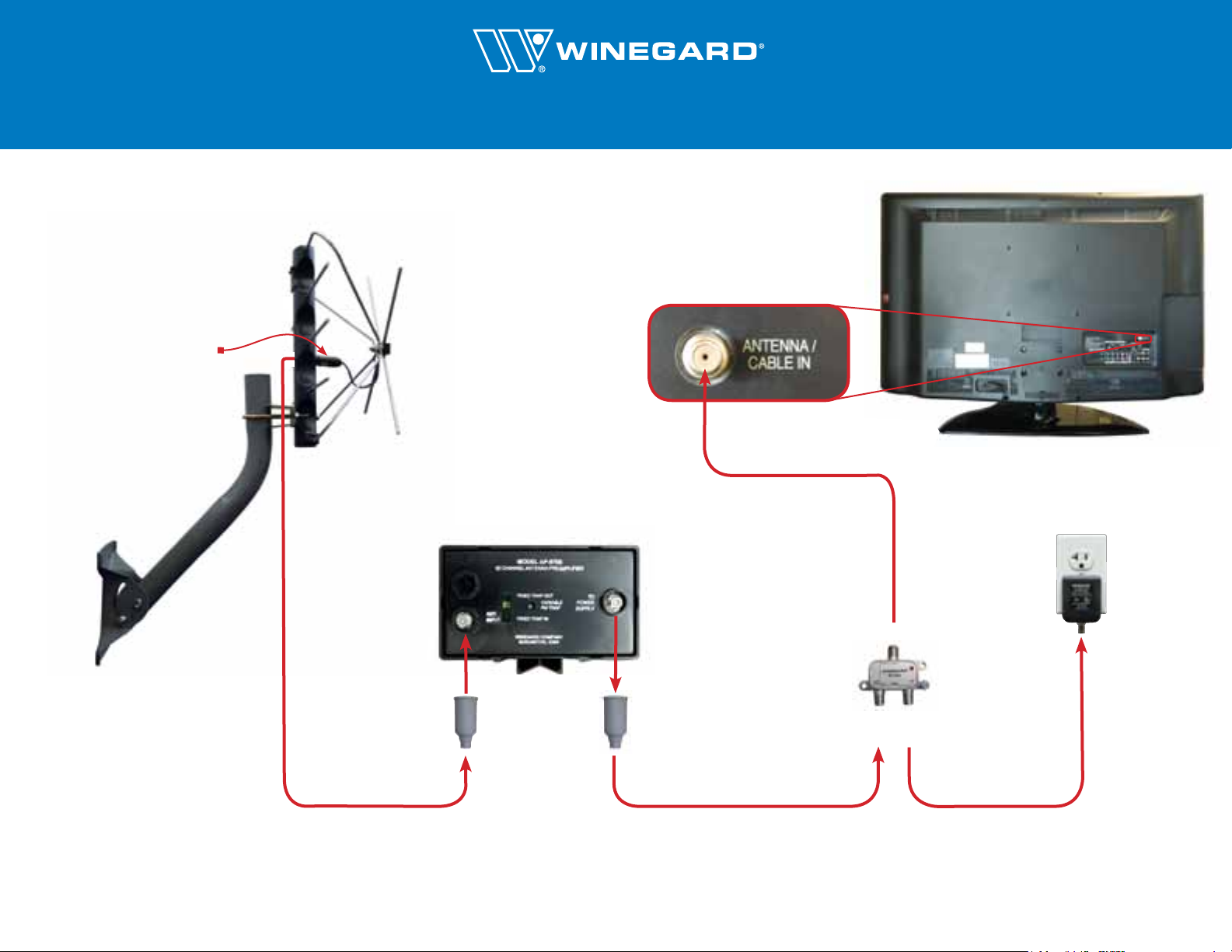
(Side View—mount not included with all models)
Note: the matching transformer
must be connected as described
on page 4 of the manual.
Wiring Diagram for FREEVISION® Antenna with Preamplifier
Back of TV
FREEVISION® Antenna
Antenna/Cable In
Coax Connection Port
3’–6’ Standard Coax Cable
Antenna Input
Underside of Preamplifier
Coax Cable
Power Supply Input
TV Input
AC Adaptor
Power
Inserter
Slide a weather
boot over each
coax cable.
Ant.
Input
Power
Input
Coax Cable Coax Cable
Winegard model AP-8700 preamplifier and model PS-1403 power inserter are shown above.
Winegard Company • 3000 Kirkwood St. • Burlington, IA 52601-2000 • 800-288-8094 • fax 800-247-8221 • www.winegard.com • Printed in U.S.A. ©2011 Winegard Company • WC-1051
Page 3

Wiring Diagram for FREEVISION® Antenna with Existing Indoor Coax Connection
Coax Connection on TV
Existing Coax
Connection*
Cable
x
Coa
FREEVISION®
Antenna
x
Coa
Cable
Antenna/Cable In
Coax Connection Port
Coax Cable
*The existing coax connection may be a 2-, 3-, 4- or 6- port splitter. A 2-port splitter is shown here.
Depending on the amount of signal received, a distribution amplifier may be required to power the system. Winegard recommends model HDA-100 distribution amplifier.
Winegard Company • 3000 Kirkwood St. • Burlington, IA 52601-2000 • 800-288-8094 • fax 800-247-8221 • www.winegard.com • Printed in U.S.A. ©2011 Winegard Company • WC-1051
Page 4

Wiring Diagram for FREEVISION® Antenna with Grounding Block and Existing Coax Connection
Coax Connection on TV
FREEVISION®
Point toward
stations.
Note: ground wire
(#8 or larger)
must run from
grounding block
to ground rod
(not shown here).
Antenna
Grounding
Block
Coax Cable
OUT
OUT
IN
Existing Coax
Connection*
Coax
Antenna/Cable In
Coax Connection Port
e
l
b
Ca
*The existing coax connection may be a 2-, 3-, 4- or 6- port splitter. A 2-port splitter is shown here.
Depending on the amount of signal received, a distribution amplifier or preamplifier may be required to power the system. Winegard recommends model HDA-100 distribution amplifier or AP-8700 preamplifier.
Refer to the National Electronic Code for antenna grounding specifications.
Winegard Company • 3000 Kirkwood St. • Burlington, IA 52601-2000 • 800-288-8094 • fax 800-247-8221 • www.winegard.com • Printed in U.S.A. ©2011 Winegard Company • WC-1051
Page 5

Wiring Diagram for FREEVISION® Antenna with Preamplifier, Grounding Block & Existing Coax Connection
Power
Inserter
Preamplifier Connections Coax Connection on TV
Underside of Preamplifier
FREEVISION®
Point toward
stations.
Preamplifier
Note: ground wire
(#8 or larger)
must run from
grounding block
to ground rod
(not shown here).
Antenna
Grounding
Block
OUT
IN
OUT
Existing Coax
Connection*
Antenna Input
Power Supply Input
e
l
b
Ca
Coax
Antenna/Cable In
Coax Port
*The existing coax connection must be a splitter that is AC/DC passive on one leg only. The power supply must be connected to the AC/DC passive leg of the existing coax connection.
Refer to the National Electronic Code for antenna grounding specifications.
Winegard Company • 3000 Kirkwood St. • Burlington, IA 52601-2000 • 800-288-8094 • fax 800-247-8221 • www.winegard.com • Printed in U.S.A. ©2011 Winegard Company • WC-1051
 Loading...