

Page 1
Replacement DISH® 1000
LNB Assembly
www.winegard.com/mobile
For Technical Services,
email help@winegard.com or call 1-800-788-4417
2452138
Page 2
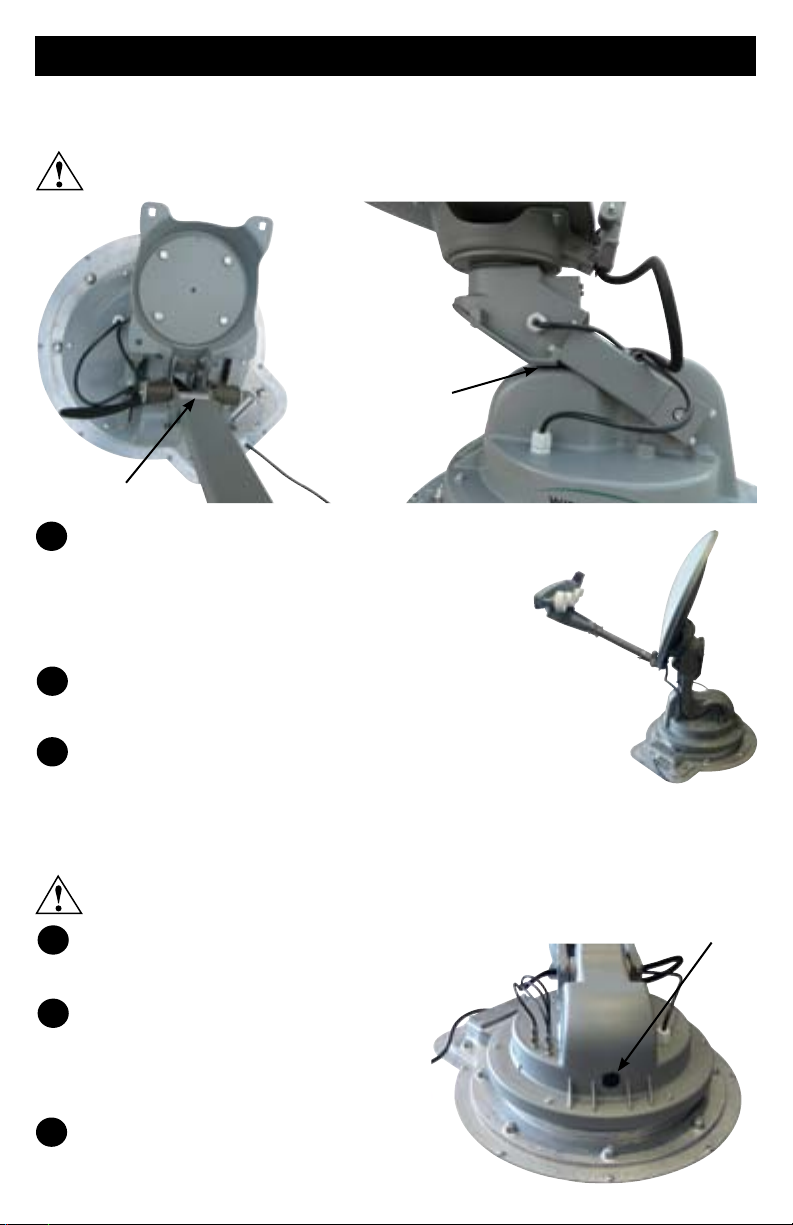
Raising the Antenna
Follow the steps below to raise the antenna for reflector, bracket, and LNB
assembly removal.
Pay attention to the pinch points as the antenna raises. See below.
Top View Side View
Pinch Point
Pinch Point
1
Press [POWER], and hold for two seconds to turn
on the TRAV’LER® interface box. Wait until the
interface box finishes “connecting to antenna.”
The TRAV’LER antenna may enter the search
routine after ten seconds.
As the antenna raises, press [POWER] and [SELECT]
2
at the same time. The antenna should stop moving.
3
Unplug the TRAV’LER interface. Continue with
reflector removal.
If you cannot get the antenna to raise by following the above instructions,
you may have to raise the antenna with the emergency manual stow drive.
Emergency manual stow is meant as a last resort!
1
Unplug the TRAV’LER interface, and remove
Plastic bolt
the plastic bolt from the back of the mount.
Insert a 3/8 socket extension into
2
this auxiliary drive. Turn the
auxiliary drive counterclockwise to
raise the unit. Do not use a drill!
3
After raising the unit, continue with
the next section to remove the
reflector and LNB assembly.
Page 3
Removing the Reflector and LNB Assembly
1
If converting a DIRECTV SWM Slimline antenna to a DISH TRAV’LER antenna,
remove the power inserter and SWM splitter; these will not be used.
2
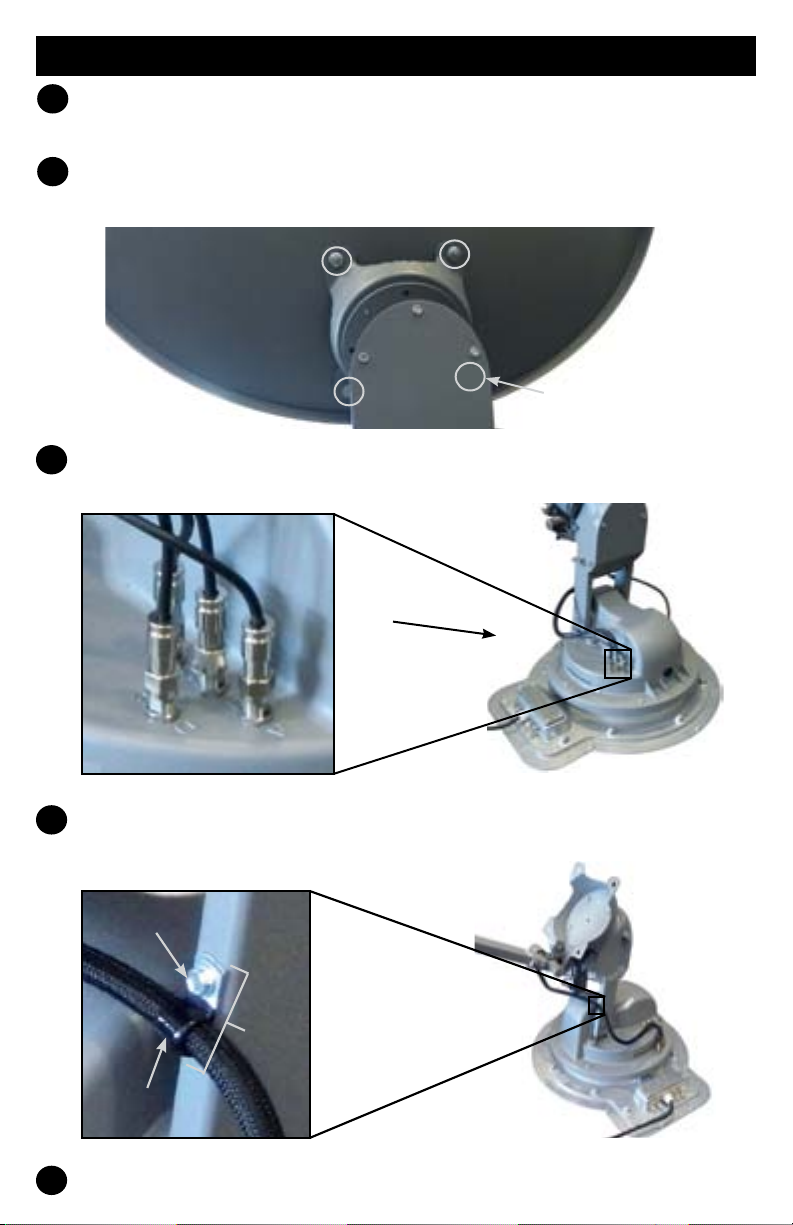
Remove the four reflector nuts and bolts, and remove the dish. Set the
nuts and bolts aside.
Reflector nut not shown
3
Disconnect the coaxial cables from the turret. Note that the D port will not
be present on a SWM TRAV’LER antenna.
Turret
Remove the bolt holding the cable harness to the unit, and detach the
4
cable harness from the lift arm.
Bolt
Lift
Arm
Cable
harness
Cable
clamp
Set the bolt aside; you will need this later.
5
Page 4

6
Remove the bolts holding the reflector bracket to the skew housing.
Reflector bracket
Skew housing
If replacing a Slimline assembly with a
NOTE
the stiffener plate inside the reflector bracket.
7
NOTE
DISH assembly, remove and set aside
Remove the LNB arm assembly, and set aside.
If replacing a Slimline assembly with a DISH assembly, remove the
four bolts from the adaptor plate, and remove the adaptor plate.
Stiffener
plate
Adaptor plate
Bolts
Installing the DISH Reflector and LNB Assembly
If replacing a Slimline assembly with a DISH assembly, align the
NOTE
groove on the skew assembly hub. Fit the small post into the groove. Secure
the adaptor plate to the hub with the four supplied ¼ inch Allen screws.
small post on the back of the DISH 1000 adaptor plate with the small
Groove
Post
Page 5

1
Align the four holes on the inside of the reflector bracket with the four
marked holes in the adaptor plate. See image below for the holes to align
with the reflector bracket and adaptor plate. The numbers on the reflector
bracket and adaptor plate should match.
1
4
The bracket should be installed so that the LNB
TIP
arm assembly is at the bottom of this plate.
Replace the supplied 3/16 Allen screws through
2
these four holes, and tighten.
After the bracket has been installed, connect and
3
tighten the coaxial cables. These can be re-connected
in any order, but port D should be left open.
Install the provided F-cap on port D. The F-cap will not
4
be used if converting from a SWM TRAV’LER antenna.
5
Find the cable tie on the coax cables that you just connected to the
mount. Place the coax cable clamp on the cables just above this cable
tie. Carefully screw this coax cable to the lift arm using the 5/16 inch
screw provided.
2
3
1
4
2
3
4
1
2
3
F-cap
Be careful not to strip out the hole for the 5/16 inch screws when you
replace the clamp holding the coax cables to the arm. Do not user a
power tool.
If the cable tie is missing, install the clamp fourteen inches from the
NOTE
6
7
end of the connectors.
Align the four outer holes in the reflector bracket with the four
corresponding holes in the reflector. Install a bolt through each hole on
the front of the reflector, and install a nut on each bolt. Tighten.
Use the provided packaging to re-package the removed LNB and
attached cables. If you are an RP-SK21 user, see Re-packaging the
Removed LNB for RP-SK21 Users. If you are an OE-DISH user, see
Re-packaging the Removed LNB for OE-DISH Users.
Page 6

Setting the IDU for DISH 1000
1
Press and hold [POWER] for two seconds or until the TRAV’LER interface
displays “POWER ON.”
Now that the power is on, release the [POWER] button.
2
3
Press and hold the [ENTER] button for two seconds.The TRAV’LER
interface will ask if you wish to enter the User Menu. Press [SELECT] to
choose “Yes”; then, press [ENTER].
4
The User Menu consists of four choices: Search Mode, Diagnostics,
Installation, and Exit. Press [SELECT] until the asterisk is next to
“Installation” and then press [ENTER].
The interface box will ask for a password. Press [ENTER] four times to
5
enter code “0000” on the display.
Press [ENTER] to choose “Select Antenna.”
6
Press [SELECT] until the asterisk is next to your mount type (SM Mount
7
or LG Mount), and then press [ENTER]. The mount type can be found on
the sticker on the TRAV’LER mount.
Selecting the incorrect mount type can result in damage to the unit or the RV.
8
Enter the four digit code for your mount type found on the sticker on the
TRAV’LER mount. Enter code 0022 for the SM mount or code 2112 for the
LG mount. Press [SELECT] to increase each number. Press [ENTER].
Press [SELECT] until the asterisk is next to DISH 1000. Press [ENTER].
9
10
Press [SELECT] until the asterisk is next to “Yes.” Press [ENTER].
11
The TRAV’LER interface box will display “in progress” and then “Success”.
Press [ENTER] and then choose [SELECT] until the asterisk is next to
12
Installation. Press [ENTER].
Page 7

If you had to raise the antenna with the emergency manual stow drive,
follow the instructions below for calibrating the elevation motor.
1
From the installation menu, press [SELECT] to move the asterisk to
“Calibrate EL”; then, press [ENTER].
2
Press [SELECT] to move the asterisk to “Yes.”
Press [ENTER] to start the elevation calibration procedure. The LCD
3
should now display “Calibrate EL In Progress.”
4
After a few moments, the TRAV’LER interface box will display “On EL
Hard Stop?/Yes *No.” Check that the antenna is against the hard stop.
If the antenna is against the hard stop, the antenna will be pointing
TIP
upward as far as it can go.
5
Press [SELECT] to move the asterisk to “Yes” if the antenna is against its
hard stop.
6
Press [ENTER], and the LCD will display “Calibrate EL Success.” Press
and hold [POWER] for two seconds to stow the antenna.
Re-packaging the Removed LNB for RP-SK21 Users
Place the removed parts into the box with original packaging, and ship to
Winegard Company at 3111 Kirkwood St., Burlington, IA 52601.
Re-packaging the Removed LNB for OE-DISH Users
Only the LNB and cables need to be returned to Winegard. Remove the
NOTE
1 2
LNB and cables from the arm assembly, then follow the steps below.
Using the smaller cardboard box,
place two sheets of void fill in
the box so that they form an ‘X’.
Push the two sheets of void fill to
the bottom of the box.
Page 8

3 4
Place another two sheets of void
fill in the cardboard box, and
place the LNB on top of these
sheets of void fill.
Position the LNB in the center of
the box. Make sure the cables
are still connected to the LNB.
Place two sheets of void fill in the
5 6
cardboard box, and push these
two sheets into the box so that
they cover the LNB.
7
Return the package to 3111 Kirkwood St., Burlington, IA 52601. If a label
Place an additional two sheets of
void fill in the cardboard box so
that they form an ‘X’; close the
box, and tape it closed.
has not been provided, use Winegard’s UPS shipping account, 530400, to
return the package to Winegard Company.
Winegard Company • 3000 Kirkwood Street • Burlington, IA 52601
1-800-288-8094 • Fax 319-754-0787 • www.winegard.com • Printed in U.S.A.
©2008 Winegard Company Rev5 1/14 2452138
Winegard and TRAV’LER are registered trademarks of Winegard Company.
DISH is a registered trademark of DISH Network L.L.C.
 Loading...