

Page 1
SunTura HD Solar Tracker Kit Manual
Revision 1.0
Page 1 of 11
WindyNation
08/09/2012
WindyNation
SUNTURA HD SOLAR TRACKER
SOT-TRKS-NFHD
User’s Manual
Page 2

SunTura HD Solar Tracker Kit Manual
Revision 1.0
Page 2 of 11
WindyNation
08/09/2012
Table of Contents
1! Introduction ................................................................................................................................................ 3!
1.1! Limited Warranty ............................................................................................................................... 3!
1.2! Restrictions ........................................................................................................................................ 3!
1.3! Warranty Claims & Return Procedures ............................................................................................. 3!
1.4! Disclaimer .......................................................................................................................................... 4!
1.5! Limitation of Liability .......................................................................................................................... 4!
2! Product Overview ....................................................................................................................................... 5!
2.1! Features ............................................................................................................................................ 5!
2.2! Safety Precautions ............................................................................................................................ 5!
3! Installation .................................................................................................................................................. 5!
3.1! Parts List ............................................................................................................................................ 5!
3.2! General Installation Guidelines .......................................................................................................... 5!
3.2.1! Electronics Box Installation ............................................................................................................ 6!
3.2.2! North/South Linear Actuator Installation ........................................................................................ 6!
3.2.3! East/West Linear Actuator Installation ........................................................................................... 7!
3.2.4! Photo Sensor Installation ............................................................................................................... 8!
3.3! Fine Tuning the LED’s for Optimal Solar Tracking ............................................................................ 9!
4! Troubleshooting And Support .................................................................................................................. 10!
4.1! Care ................................................................................................................................................. 10!
4.2! Troubleshooting ............................................................................................................................... 10!
4.3! Support ............................................................................................................................................ 10!
Page 3

SunTura HD Solar Tracker Kit Manual
Revision 1.0
Page 3 of 11
WindyNation
08/09/2012
INTRODUCTION 1
Windy Nation Inc. (“Windy Nation”) is not assembling the Solar Tracker, or any other product offered by
Windy Nation. Windy Nation, and its directors, officers, and employees disclaim, and by purchasing a Windy
Nation product you accept all liability and responsibility for damage to property, injury, or death arising out of
or related to the use or misuse of any product offered by Windy Nation.
LIMITED WARRANTY 1.1
Windy Nation warrants that the Solar Tracker (the “Product”), will be free from manufacturing defects in
materials and workmanship under normal authorized use consistent with product instructions for a period of
one (1) year from the date the original purchaser (“Customer”) receives the Product (the “Warranty Period”).
This warranty extends only to the original purchaser. The Customer’s sole and exclusive remedy and the
entire liability of Windy Nation, its suppliers and affiliates for breach of the warranty is, at Windy Nation’s
option, either (i) to replace the Product (or defective component part(s)) with a new or reconditioned Product
(or component part(s)); (ii) to repair the reported problem; or (iii) to refund the purchase price of the Product.
Repaired or replaced products are warranted for the remainder of the original warranty period only. No
employee, agent, dealer or other person is authorized to give any warranties on behalf of Windy Nation not
expressly set forth in this limited warranty.
RESTRICTIONS 1.2
No warranty will apply if the Product (i) has been altered or modified except by Windy Nation; (ii) has not
been installed, operated, repaired, or maintained in accordance with instructions supplied by Windy Nation;
(iii) has been subjected to abnormal physical, thermal or electrical stress, misuse, negligence, or accident. If
Windy Nation determines that the problem with the Product is not due to a manufacturing defect in Windy
Nation’s workmanship or materials, or otherwise does not qualify for warranty repair, then the Customer will
be responsible for the costs of all necessary repairs and expenses incurred by Windy Nation.
WARRANTY CLAIMS & RETURN PROCEDURES 1.3
To be eligible for service under this warranty, the Customer must submit a service request within the
Warranty Period by contacting Windy Nation in writing or via telephone and obtaining a Returned Materials
Authorization (“RMA”) number. This RMA must be obtained before returning any product under this warranty.
Notification must include a description of the alleged defect, the manner in which the Product was used, the
serial number, and the original purchase date in addition to the name, address, and telephone number of the
Customer. Within five (5) business days of the date of notification, Windy Nation will provide the Customer
with an RMA number and the location to which the Customer must return the defective Product. Any Product
returned for warranty service shall be shipped at the expense and risk of the Customer. The Customer must
return the entire Product kit (or, if authorized by Windy Nation, the defective component parts), within fifteen
(15) days after issuance of the RMA number. Windy Nation will be under no obligation to accept any returned
Product that does not have a valid RMA number. Customer’s failure to return the Product within fifteen (15)
days of its receipt of an RMA number may result in cancellation of the RMA. All parts that Windy Nation
Page 4

SunTura HD Solar Tracker Kit Manual
Revision 1.0
Page 4 of 11
WindyNation
08/09/2012
replaces shall become Windy Nation’s property on the date Windy Nation ships the repaired Product or part
back to the Customer. Windy Nation will use all reasonable efforts within thirty (30) days of receipt of the
defective Product to repair or replace such Product. If a warranty claim is invalid for any reason, the
Customer will be charged at Windy Nation’s then-current rates for services performed and will be charged for
all necessary repairs and expense incurred by Windy Nation. If Windy Nation determines that a warranty
claim is valid, it will ship the repaired or replaced Product to Customer at Windy Nation’s cost.
DISCLAIMER 1.4
EXCEPT FOR THE EXPRESS LIMITED WARRANTY SET FORTH IN THE PREVIOUS PARAGRAPH,
WINDY NATION DISCLAIMS ALL WARRANTIES, EXPRESS, IMPLIED AND STATUTORY INCLUDING,
WITHOUT LIMITATION, THE IMPLIED WARRANTIES OF MERCHANTABILITY AND FITNESS FOR A
PARTICULAR PURPOSE WITH RESPECT TO ANY PRODUCTS PROVIDED BY WINDY NATION. NO
ORAL OR WRITTEN INFORMATION OR ADVICE GIVEN BY WINDY NATION, ITS DEALERS,
DISTRIBUTORS, AGENTS OR EMPLOYEES SHALL IN ANY WAY INCREASE THE SCOPE OF THIS
WARRANTY. WINDY NATION DOES NOT WARRANT THAT THE QUALITY OR PERFORMANCE OF THE
PRODUCTS WILL MEET YOUR REQUIREMENTS OR THAT YOU WILL BE ABLE TO ACHIEVE ANY
PARTICULAR RESULTS FROM USE OR MODIFICATION OF THE PRODUCTS. Some jurisdictions do not
allow the limitation or exclusion of implied warranties or how long an implied warranty may last, so the above
limitations may not apply to you. In any such jurisdiction, the warranty shall be limited to the minimum
warranty and period required by law.
WINDY NATION EXPRESSLY DISCLAIMS ALL LIABILITY FOR BODILY INJURIES OR DEATH THAT MAY
OCCUR, DIRECTLY OR INDIRECTLY, BY USE OF THE PRODUCT BY ANY PERSON.
LIMITATION OF LIABILITY 1.5
UNDER NO CIRCUMSTANCES WILL WINDY NATION OR ITS AFFILIATES OR SUPPLIERS BE LIABLE
OR RESPONSIBLE FOR ANY LOSS OF USE, INTERRUPTION OF BUSINESS, LOST PROFITS, LOST
DATA, OR INDIRECT, SPECIAL, INCIDENTAL, OR CONSEQUENTIAL DAMAGES OF ANY KIND
REGARDLESS OF THE FORM OF ACTION, WHETHER IN CONTRACT, TORT (INCLUDING
NEGLIGENCE), STRICT LIABILITY OR OTHERWISE, EVEN IF WINDY NATION OR ITS AFFILIATE OR
SUPPLIER HAS BEEN ADVISED OF THE POSSIBILITY OF SUCH DAMAGE.
Some states do not allow the exclusion or limitation of incidental or consequential damages, so these
limitations may not apply to you. Neither Windy Nation nor its affiliates or suppliers will be held liable or
responsible for any damage or loss to any items or products connected to, powered by or otherwise attached
to the Product. The total cumulative liability to Customer, from all causes of action and all theories of liability,
will be limited to and will not exceed the purchase price of the Product paid by Customer. This warranty gives
the Customer specific legal rights and the Customer may also have other legal rights that vary from state to
state.
Page 5

SunTura HD Solar Tracker Kit Manual
Revision 1.0
Page 5 of 11
WindyNation
08/09/2012
PRODUCT OVERVIEW 2
Building a complete solar tracking system has never been easier. The SunTura Solar Tracker Kit can be
used directly on 12 volt or 24 volt systems. If you plan on using the SunTura Solar Tracker Kit on a grid tie
system, we can supply you with a 12 volt power supply which can be plugged into the grid (110 AC or 220
AC).
FEATURES 2.1
• 100% pre-wired Kit
• Dual axis tracker provides up to 40% more power production than fixed solar panels.
• Engineered to hold up to 500 Watts of solar panels
• All electronics are water-tight with IP65 rated enclosures
SAFETY PRECAUTIONS 2.2
CAUTION: Never approach a solar tracker while the SunTura Solar Tracker electronics are “on”. The solar
tracker can move unexpectedly and the powerful linear actuators can cause serious injury or death. Always
disconnect the SunTura Solar Tracker electronics from its power supply before approaching the solar
tracker.
INSTALLATION 3
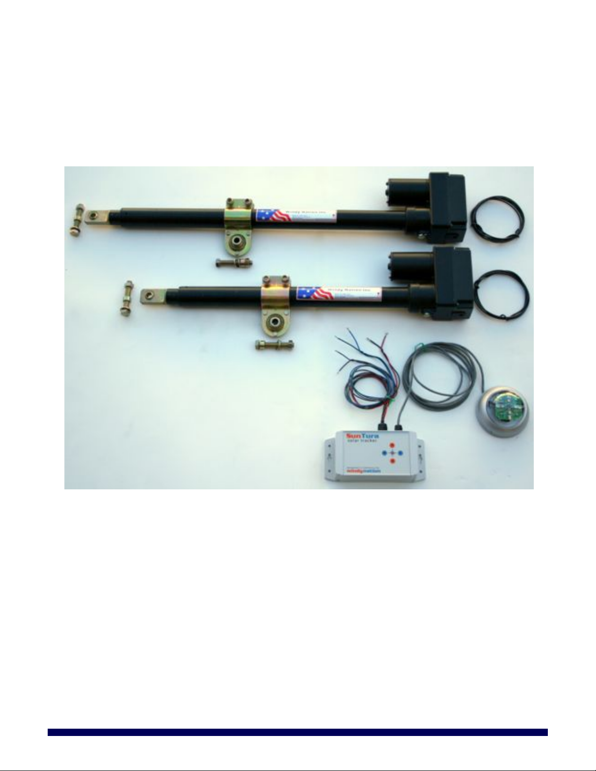
PARTS LIST 3.1
1. Electronics Box
2. PhotoSensor
3. East/West Linear Actuator
4. North/South Linear Actuator (Only included in the Dual Axis Kit)
Figure 1: SunTura Solar Tracker Kit Parts List
GENERAL INSTALLATION GUIDELINES 3.2
The SunTura Solar Tracker Kit provides the electronics used to build a dual axis solar tracker. The two linear
actuators included with the SunTura Solar Tracker Kit are each capable of a dynamic load of 1250 lbs. In
real world conditions, this means that the SunTura Solar Tracker Kit should not be used on solar trackers in
excess of 1500 Watts of solar panels.
Page 6

SunTura HD Solar Tracker Kit Manual
Revision 1.0
Page 6 of 11
WindyNation
08/09/2012
3.2.1 Electronics Box Installation
The Electronics Box has a 20 amp fuse on the circuit board located on its inside. There is also one additional
spare fuse. The fuse protects the SunTura Solar Tracker electronics from a short circuit. If you accidentally
short circuit the electronics, simply replace the blown fuse with the spare fuse. Do NOT bypass the fuse.
Additionally, there are four buttons on the top of the Electronics Box which allow one to manually move the
linear actuators in the north, south, east and west directions. See Figure 2 below.
Figure 2: Electronics Box manual controls and fuse locations.
WARNING: Do NOT connect the SunTura Solar Tracker electronics to the power supply until you
have completely finished the installation process and all people are safely away from the solar
tracker’s range of motion!
The red and black wires coming out of the Electronics Box are the power supply wires. These wires need to
be connected to a 12 through 24 volt DC power supply. Some good examples of power supplies are a 12 volt
battery, a 24 volt battery or a 12/24 VDC power supply that plugs into an AC wall outlet. The DC power
supply must be able to supply a minimum of 12 amps. Additionally, the DC power supply can NEVER
exceed 30 volts DC or the SunTura Solar Tracker electronics will be permanently destroyed. Even if
the voltages exceeds 30 VDC for only just an instant, the electronics will be permanently destroyed! Windy
Nation Inc. recommends a car sized 12 volt or 18 volt battery to power the SunTura Solar Tracker
electronics. The red wire coming out of the Electronics Box connects to the positive output of the DC power
supply. The black wire coming out of the Electronics Box connects to the negative output of the DC power
supply. See Figure 3 below.
Figure 3: Connecting the SunTura Solar Tracker Kit to a power supply.
3.2.2 North/South Linear Actuator Installation
(Note: The North/South linear actuator is only included in the Dual Axis Kit. If you purchased the Single Axis
Kit, then skip section 3.2.2 and proceed to section 3.2.3)
The North/South linear actuator has a stroke length of 18 inches (the shorter of the two linear actuators
included in the kit). It will be wired to the SunTura Tracking Electronics in the following manner: If the sun is
Page 7

SunTura HD Solar Tracker Kit Manual
Revision 1.0
Page 7 of 11
WindyNation
08/09/2012
located to the north of the solar tracker, the north/south linear actuator will extend so it positions the solar
panels perpendicular to the sun’s light rays. To connect the north/south linear actuator to the Electronics Box
simply remove the plastic cover on the bottom of the linear actuator by removing the four screws. Next,
follow the wiring instructions in Figure 4 below for wiring the Electronics Box to the north/south linear
actuator. Make sure that you use the appropriate length of wire to cover the full range of motion of the solar
tracker (Extra wire is included in this kit.).
Figure 4: Connecting the North/South Actuator to the Electronics Box.
.Note: If you wish for the north/south linear actuator to retract when the sun is to the north of the solar
tracker, then you can simply switch the green and blue wires that will be connected to the north/south linear
actuator.
3.2.3 East/West Linear Actuator Installation
The east/west linear actuator has a stroke length of 24 inches. It is wired to the SunTura Tracking Electronics
in the following manner: If the sun is located to the west of the solar tracker, the east/west linear actuator will
extend so it positions the solar panels perpendicular to the sun’s light rays. To connect the east/west linear
actuator to the Electronics Box simply remove the plastic cover on the bottom of the linear actuator by
removing the four screws. Next, follow the wiring instructions in Figure 5 below for wiring the Electronics Box
to the east/west linear actuator. Make sure that you use the appropriate length of wire to cover the full range
of motion of the solar tracker (Extra wire is included in this kit.).
Figure 5: Connecting the East/West Actuator to the Electronics Box.
Page 8

SunTura HD Solar Tracker Kit Manual
Revision 1.0
Page 8 of 11
WindyNation
08/09/2012
If you wish for the east/west linear actuator to retract when the sun is to the west of the solar tracker, then
you can simply switch the grey and brown wires that will be connected to east/west linear actuator.
Note: Before powering up the SunTura Solar Tracker electronics be certain there is enough slack in the
wires between both Linear Actuators and the Electronics Box to cover the full range of motion of the solar
tracker. Extra wire is included in this kit.
3.2.4 Photo Sensor Installation
For northern hemisphere installations, it is recommended that the Photo Sensor is mounted on the northern
side of the solar tracker and that the Photo Sensor has an unobstructed view of the sky (Photo Sensors that
are being installed in the southern hemisphere should be mounted on the southern side of the solar tracker.)
The side of the Photo Sensor circuit board that is labeled “NORTH” needs to be pointed towards the north.
Note: The edge of the Photo Sensor circuit board that is labeled “NORTH” will be perpendicular (90 degrees)
to the north; See Figure 4 below.
Figure 4: Photo Sensor mounting orientation
3.2.4.1 Mounting the Photo Sensor
Use the included Allen wrench to loosen the two set screws that secure the dome to the Photo Sensor. After
the set screws are removed, pull off the Photo Sensor Dome. Note that it is easier to remove the Photo
Sensor Dome if a flat head screw driver is used to help lift up the Photo sensor Dome. See Figure 5 below.
Figure 5: Use Allen wrench to loosen set screws and remove Photo Sensor Dome with flat head
screw driver.
Page 9

SunTura HD Solar Tracker Kit Manual
Revision 1.0
Page 9 of 11
WindyNation
08/09/2012
Next, mount the included screw sets into the three holes on the Photo Sensor. These screws can be used to
mount the Photo Sensor to the solar tracker.
Figure 6: Mounting Fasteners to Photo Sensor.
FINE TUNING THE LED’S FOR OPTIMAL SOLAR TRACKING 3.3
This step is optional. The SunTura Solar Tracker should track the sun with an accuracy of +/- 7 degrees or
better with no fine tuning. Mounting the Photo Sensor slightly off angle (human error) with respect to the
solar tracker can lead to a slight tracking inaccuracy. If you wish, the LED’s can be adjusted to provide
optimal tracking accuracy. (Do NOT attempt to fine tune the LED’s until the Photo Sensor has been
fastened to the solar tracker and is in its final position) To do this, first mount an object on the solar
tracker that is perpendicular to the solar panels. This will be used to generate a shadow from the sun’s light.
Below is an example.
Figure 7: Bolt mounted perpendicular to solar panel angle.
The LED’s on the Photo Sensor circuit board can be slightly adjusted to fine tune the accuracy of the solar
tracking. The goal is to eliminate the shadow casted by the bolt in Figure 7. The LED’s can be moved slightly
up or down to accomplish this task. Warning: Do NOT bend the LED’s more than 15 degrees from the factory
set positions!
Page 10

SunTura HD Solar Tracker Kit Manual
Revision 1.0
Page 10 of 11
WindyNation
08/09/2012
Figure 8: Bending directions for fine tuning the eight LED’s on the Photo Sensor circuit board.
To adjust the LED’s use the following table:
LED
Adjustment Direction
Result
D1 and D2
move up
move down
track more north
track more south
D3 and D4
move up
move down
track more south
track more north
D5 and D6
move up
move down
track more east
track more west
D7 and D8
move up
move down
track more west
track more east
It is highly recommended that the LED’s are adjusted on a sunny day with no clouds blocking the sun’s light.
Clouds or anything else slightly blocking the sun’s light will negatively affect the accuracy of the LED fine
tuning.
Once you are finished adjusting the LED’s on the Photo Sensor, re-attach the Photo Sensor Dome and
tighten the set screws using the Allen wrench.
TROUBLESHOOTING AND SUPPORT 4
The SunTura Solar Tracker Kit is ruggedly constructed and requires minimal care.
CARE 4.1
To clean your tracker, moisten a cloth with a few drops of mild hand dishwashing detergent in a cup of
lukewarm water and gently wipe clean.
TROUBLESHOOTING 4.2
Problem
Possible Remedies
Tracker is not accurately
tracking the sun
Follow the Fine-tuning steps included in Section 3.3
Tracker is not working
1. Check the fuse as shown in Section 3.2.1
2. Test the source voltage to the tracker Electronics Box
3. Check connections to the red and black wires going to the Electronics Box
SUPPORT 4.3
If you are experiencing technical problems, and cannot find a solution in this manual, you can contact Windy
Nation Inc. for further assistance.
• Call: (805) 323-6445
• Email: info@windynation.com
• Write: 1082 Front Street, Unit B, Ventura, CA 93001
Page 11

SunTura HD Solar Tracker Kit Manual
Revision 1.0
Page 11 of 11
WindyNation
08/09/2012
For challenging issues or to just ask a question, consider using our FREE Community Forums! Consult our
community of DIYers for fast answers to all your questions.
Post on our Forums: http://www.windynation.com/community/
 Loading...