

Page 1
WindyNation
Rover Wind Turbine Owner’s Manual
Rev 1.0 Copyright 2011
1
Page 2

Table of Contents
Rover Wind Turbine Limited Warranty and Product Disclaimer……3-4
Rover Wind Turbine Parts List……5
Installation Warnings…..5
Technical Specifications……5
Rover Wind Turbine Assembly and Maintenance Instructions……6-13
Section 1.0: Attaching the blades to the hub……6
Section 2.0: Fasten Directional Tail to Yaw Mount……7
Section 3.0: Mount Rover Wind Turbine to Tower……8-11
Section 4.0: Attach Blade/Hub Assembly to Generator Shaft……11
Section 5.0: Final Assembly of the Rover Wind Turbine……12
Section 6.0: Locating a Site for the Rover Wind Turbine……12
Section 7.0: Main Operational Characteristics of the Rover Wind Turbine……12
Section 8.0: Battery Charge Controller Requirements for the Rover Wind Turbine……13
Section 9.0 Rover Wind Turbine Maintenance Instructions……14
2
Page 3

ROVER WIND TURBINE LIMITED WARRANTY AND
PRODUCT DISCLAIMER
Windy Nation Inc. (“Windy Nation”) is not assembling the wind unit, installing the blade system, or any other
product offered by Windy Nation. Windy Nation, and its directors, officers and employees disclaim, and by
purchasing a Windy Nation wind-powered product you accept all liability and responsibility for damage to
property, injury, or death arising out of or related to the use or misuse of any product offered by Windy Nation.
Limited Warranty
Windy Nation warrants that the Rover (the “Product”), including its component parts supplied by Windy
Nation, will be free from manufacturing defects in materials and workmanship under normal authorized use
consistent with product instructions for a period of two (2) years from the date the original purchaser
(“Customer”) receives the Product (the “Warranty Period”). This warranty extends only to the original purchaser.
The Customer’s sole and exclusive remedy and the entire liability of Windy Nation, its suppliers and affiliates for
breach of the warranty is, at Windy Nation’s option, either (i) to replace the Product (or defective component
part(s)) with a new or reconditioned Product (or component part(s)); (ii) to repair the reported problem; or (iii) to
refund the purchase price of the Product. Repaired or replaced products are warranted for the remainder of the
original warranty period only. No employee, agent, dealer or other person is authorized to give any warranties on
behalf of Windy Nation not expressly set forth in this limited warranty.
Restrictions
No warranty will apply if the Product (i) has been altered or modified except by Windy Nation; (ii) has not been
installed, operated, repaired, or maintained in accordance with instructions supplied by Windy Nation; (iii) has
been exposed to winds exceeding 105 mph (46.9 m/s), or (iv) has been subjected to abnormal physical, thermal or
electrical stress, misuse, negligence, or accident. If Windy Nation determines that the problem with the Product is
not due to a manufacturing defect in Windy Nation’s workmanship or materials, or otherwise does not qualify for
warranty repair, then the Customer will be responsible for the costs of all necessary repairs and expenses incurred
by Windy Nation.
Warranty Claims & Return Procedures
To be eligible for service under this warranty, the Customer must submit a service request within the Warranty
Period by contacting Windy Nation in writing or via telephone and obtaining a Returned Materials Authorization
(“RMA”) number. This RMA must be obtained before returning any product under this warranty. Notification must
include a description of the alleged defect, the manner in which the Product was used, the serial number, and the
original purchase date in addition to the name, address, and telephone number of the Customer. Within five (5)
business days of the date of notification, Windy Nation will provide the Customer with an RMA number and the
location to which the Customer must return the defective Product. Any Product returned for warranty service
shall be shipped at the expense and risk of the Customer. The Customer must return the entire Product kit (or, if
authorized by Windy Nation, the defective component parts), within fifteen (15) days after issuance of the RMA
number. Windy Nation will be under no obligation to accept any returned Product that does not have a valid RMA
number. Customer’s failure to return the Product within fifteen (15) days of its receipt of an RMA number may
result in cancellation of the RMA. All parts that Windy Nation replaces shall become Windy Nation’s property on
the date Windy Nation ships the repaired Product or part back to the Customer. Windy Nation will use all
reasonable efforts within thirty (30) days of receipt of the defective Product to repair or replace such Product. If a
warranty claim is invalid for any reason, the Customer will be charged at Windy Nation’s then-current rates for
services performed and will be charged for all necessary repairs and expense incurred by Windy Nation. If Windy
Nation determines that a warranty claim is valid, it will ship the repaired or replaced Product to Customer at Windy
Nation’s cost.
Disclaimer
EXCEPT FOR THE EXPRESS LIMITED WARRANTY SET FORTH IN THE PREVIOUS PARAGRAPH, WINDY NATION
DISCLAIMS ALL WARRANTIES, EXPRESS, IMPLIED AND STATUTORY INCLUDING, WITHOUT LIMITATION, THE
IMPLIED WARRANTIES OF MERCHANTABILITY AND FITNESS FOR A PARTICULAR PURPOSE WITH RESPECT TO ANY
PRODUCTS PROVIDED BY WINDY NATION. NO ORAL OR WRITTEN INFORMATION OR ADVICE GIVEN BY WINDY
NATION, ITS DEALERS, DISTRIBUTORS, AGENTS OR EMPLOYEES SHALL IN ANY WAY INCREASE THE SCOPE OF THIS
WARRANTY. WINDY NATION DOES NOT WARRANT THAT THE QUALITY OR PERFORMANCE OF THE PRODUCTS
3
Page 4

WILL MEET YOUR REQUIREMENTS OR THAT YOU WILL BE ABLE TO ACHIEVE ANY PARTICULAR RESULTS FROM USE
OR MODIFICATION OF THE PRODUCTS. Some jurisdictions do not allow the limitation or exclusion of implied
warranties or how long an implied warranty may last, so the above limitations may not apply to you. In any such
jurisdiction, the warranty shall be limited to the minimum warranty and period required by law.
WINDY NATION EXPRESSLY DISCLAIMS ALL LIABILITY FOR BODILY INJURIES OR DEATH THAT MAY OCCUR, DIRECTLY
OR INDIRECTLY, BY USE OF THE PRODUCT BY ANY PERSON.
Limitation of Liability
UNDER NO CIRCUMSTANCES WILL WINDY NATION OR ITS AFFILIATES OR SUPPLIERS BE LIABLE OR RESPONSIBLE
FOR ANY LOSS OF USE, INTERRUPTION OF BUSINESS, LOST PROFITS, LOST DATA, OR INDIRECT, SPECIAL,
INCIDENTAL, OR CONSEQUENTIAL DAMAGES OF ANY KIND REGARDLESS OF THE FORM OF ACTION, WHETHER IN
CONTRACT, TORT (INCLUDING NEGLIGENCE), STRICT LIABILITY OR OTHERWISE, EVEN IF WINDY NATION OR ITS
AFFILIATE OR SUPPLIER HAS BEEN ADVISED OF THE POSSIBILITY OF SUCH DAMAGE.
Some states do not allow the exclusion or limitation of incidental or consequential damages, so these limitations
may not apply to you. Neither Windy Nation nor its affiliates or suppliers will be held liable or responsible for any
damage or loss to any items or products connected to, powered by or otherwise attached to the Product. The
total cumulative liability to Customer, from all causes of action and all theories of liability, will be limited to and
will not exceed the purchase price of the Product paid by Customer. This warranty gives the Customer specific
legal rights and the Customer may also have other legal rights that vary from state to state.
4
Page 5

Rover Wind Turbine Parts List
Model
Rover
Blade Rotor Diameter
60 inches
Net Weight
27 lbs. (12.3 kg)
Survival Wind Speed
105 mph (47m/s)
Initial Power Generation Wind Speed
7-8 mph (3.1 ms)
Battery Bank Specifications
Suitable for 12 or 24 volt battery banks
Rated Power
300 Watts at 28 mph wind speed
Required Fuse
30 amp for 12 volt systems
20 amp for 24 volt systems
1. Generator and yaw mount
2. Directional tail
3. Five 28 inch blades
4. Blade mounting hub
5. Stainless fasteners (nuts, bolts and washers)
Installation Warnings
Do not assemble or install the Rover Wind Turbine until you have read the
entirety of this owner’s manual!
1. It is necessary to follow the installation instructions and safety precautions included in this
owner’s manual. Failure to do so can result in serious accidents including but not limited to
property damage, serious injury, and death. Additionally, keep this owner’s manual after you
install your Rover Wind Turbine as it includes maintenance and safety information.
2. Before assembling the Rover Wind Turbine inspect all parts for any defects. If you have any
questions or concerns, contact Windy Nation Inc. or your local distributor before proceeding
with installing your Rover Wind Turbine.
3. Never install a wind turbine on a windy day. A “windy day” is defined as wind speeds in
excess of 5 mph.
4. Use proper electrical wiring and grounding techniques which are in compliance with your
country’s electrical codes.
5. Tower design and construction should be approved by a professional engineer and also
follow all local and national laws in your respective jurisdiction.
6. Do not install the Rover Wind Turbine in any location where anyone or anything can come in
contact with it. The Rover Wind Turbine has moving parts, including high rpm blades, which can
cause serious injury or death. Use common sense and exercise caution when
choosing a location to mount the Rover Wind Turbine.
Technical Specifications
5
Page 6

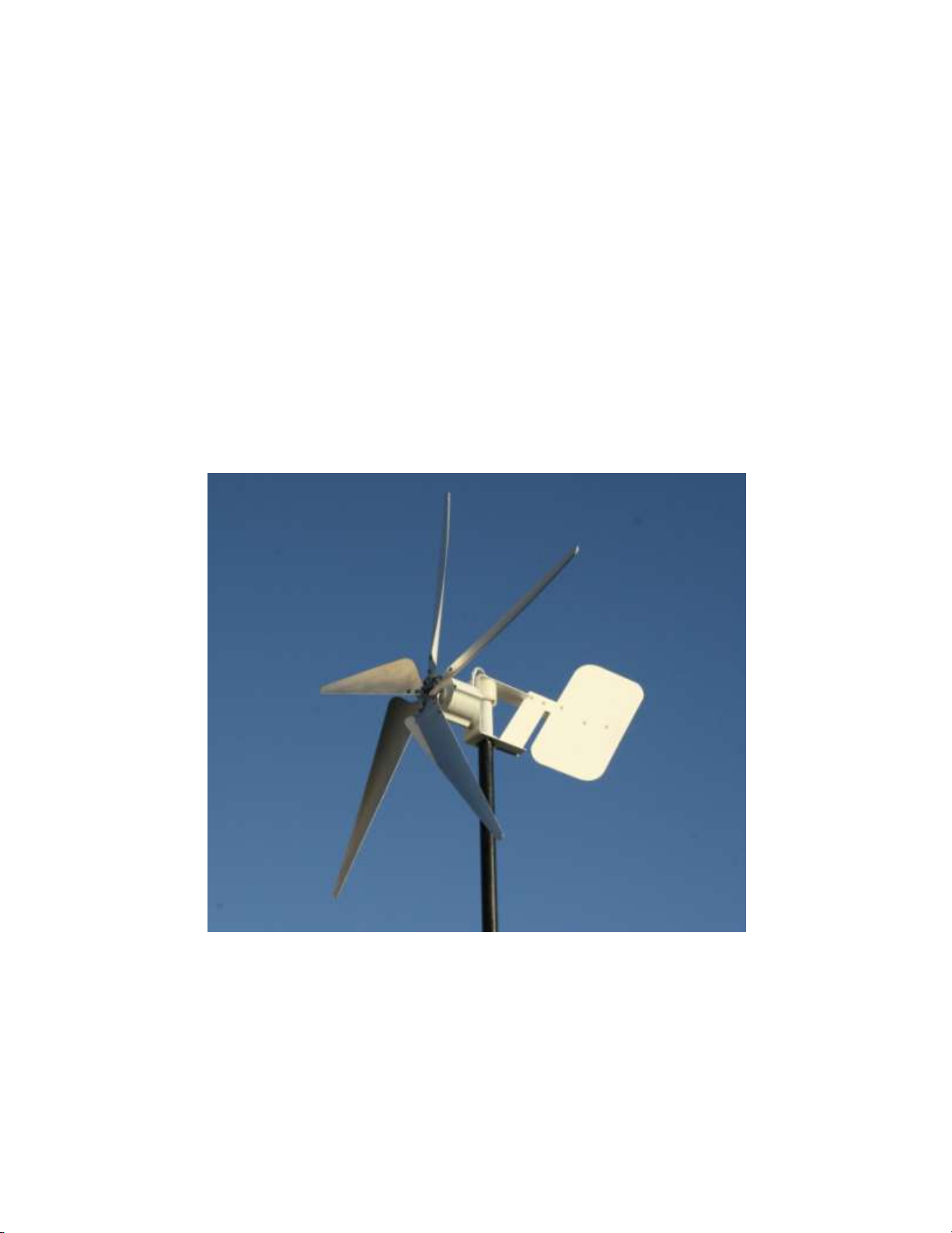
Rover Wind Turbine Assembly and Maintenance Instructions
The Rover Wind Turbine comes partially assembled. The generator head and yaw bushings are
pre-attached to the yaw mount at the factory.
Section 1.0: Attaching the blades to the hub
Figure 1
Be careful not to hit, bend or damage the blades while attaching the blades to the hub
as this could make the blades unbalanced! Once you are finished attaching the blades
to the hub, lay the blade/hub assembly on a flat surface.
Step 1: Locate the bag which is labeled “Blade to Hub Fastener Set”. This bag should contain
the following fasteners: 15 stainless steel bolts, 15 stainless steel k-lock nuts, and 15 stainless
steel flat washers. Lay the hub on a flat surface and attach the blades using the fasteners. See
instructions below.
Step 2: Place a flat washer on a bolt. Slide the bolt through its respective hole on the blade
and hub. See Picture A in Figure 1 above. On the backside of the hub, attach the k-lock nut to
the bolt as shown in Picture B of Figure 1 above. Repeat this process until all the blades are
bolted to the hub. It is necessary to tighten the k-lock nuts to a torque of 9.0 lb-ft (12.1 N·m).
6
Page 7

Section 2.0: Fasten Directional Tail to Yaw Mount
Figure 2
Step 1: Locate the fastener bag labeled “Tail Assembly Fastener Set”. There are 7 stainless
steel bolts, 7 stainless steel k-lock nuts and 14 nylon washers. Slide one nylon washer onto each
stainless steel bolt. Attach the directional tail to the yaw mount using the 7 stainless steel bolts
with nylon washers. See Picture A in Figure 2 above.
Step 2: Place the 7 remaining nylon washers onto the 7 stainless steel bolts that are securing
the Directional Tail to the Yaw Mount. Next, attach the 7 stainless steel k-lock nuts and tighten
to securely fasten the Directional Tail and Yaw Mount. See Picture B in Figure 2 above.
7
Page 8

Section 3.0: Mount Rover Wind Turbine to Tower
In general, it is easier to mount the Rover Wind Turbine Frame to the tower without the
blade/hub assembly attached. The blade and hub assembly can be attached to the generator
shaft after the wind turbine frame is mounted to the tower. If you choose to mount the blade/hub
assembly before placing the Rover Wind Turbine on a tower, then follow the blade mounting
instructions in Section 4.0 before proceeding with Section 3.0.
Figure 3
Step 1: Run three wires through the 1.5 inch schedule 40 steel tower pipe so that the wires
come out the top of the tower. See Figure 3 above. Outdoor rated three conductor extension
cord or welding cables can be used as tower pipe. It is recommended that 10 AWG wire is used
for wire runs of 50 feet or less and 8 AWG wire is recommended for wire runs of 50-100 feet.
Before continuing to Step 2, make sure that the top of the 1.5 inch Schedule 40 tower pipe is
filed smooth. The yaw bushing sits on top of the tower pipe and failure to file smooth the top of
the tower pipe where the bushing sits, could result in premature wearing of the bushing and
also inhibit the Rover Wind Turbine from properly tracking the wind direction.
8
Page 9

Figure 4
Step 2: Before mounting the Rover Wind Turbine Frame to the tower, it is recommended that
you remove the cable gland nut and the cable gland rubber grommet. This will make it easier to
pass the tower wires through the cable gland. Once this is done, pick up the Rover Wind
Turbine Frame and guide it onto the 1.5 inch Schedule 40 Tower Pipe. If you are having
difficulty guiding the three tower wires through the cable gland, tie a piece of string to the
three tower wires. Use this string to help guide the tower wires through the cable gland. See
Figure 4 above.
Figure 5
Step 3: After the Rover Wind Turbine Frame has been mounted on the tower, re-insert the
cable gland’s rubber grommet (if you removed it). Use a crescent wrench to firmly tighten the
cable gland nut. It is important to firmly tighten the cable gland nut (See Figure 5) above
9
Page 10
because it supports the weight of the wires hanging down the tower. Failure to tighten the
cable gland properly could cause the tower wires to slip downward and put tension on the
three wires coming out of the generator. This could cause damage to the generator.
For towers over 25 feet tall, a stainless steel hose clamp needs to be firmly clamped
around the three tower wires directly above the cable gland nut (See Figure 5 above). Stainless
steel hose clamps can be purchased from local hardware stores. The hose clamp adds
secondary support so that the tower wires do not slip down the tower and put unnecessary
tension on three generator wires. This is necessary for towers over 25 feet due to the added
wire weight in tall towers.
Next, connect the three tower wires to the three wires exiting the back of the
generator. Take great care in making sure these wire connections are strong and have good
continuity. It is highly advisable to cover these wire connections with outdoor rated shrink
tubing to prevent possible wire shorts and to protect the wire connections from the outdoor
elements. Remember, poorly connected wires will negatively affect the power performance of
any wind turbine and will lead to wire connection failure!
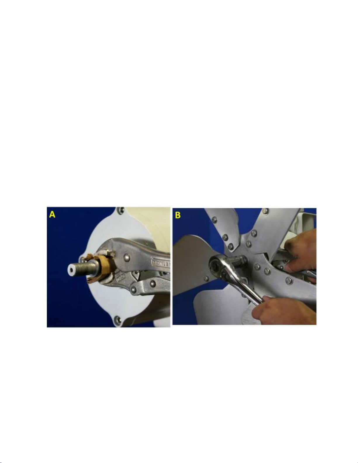
Section 4.0: Attach Blade/Hub Assembly to Generator Shaft
Figure 6
Step 1: Use a Vise Grip to immobilize the generator shaft. Insert as many layers of cardboard as
necessary to prevent the “teeth” of the Vise Grips from denting or scratching the generator
shaft. See Picture A in Figure 6 above.
Step 2: Slide the Blade/Hub Assembly onto the shaft of the generator. The blades should curve
outward and away from the generator head. Put the stainless steel flat washer, lock washer and
nut onto the threaded shaft of the generator. With one hand on the Vise Grips to immobilize
the generator shaft, securely tighten the nut on the generator shaft to a torque of 180 lb-ft (245
10
Page 11

N·m). See Picture B in Figure 6 above. Take special care not to grab or push on the blades
while tightening the generator shaft nut as this could damage the blades.
Section 5.0: Final Assembly of the Rover Wind Turbine
The Rover Wind Turbine is now completely assembled and mounted on the
tower. Before continuing, look over the entire wind turbine to be sure everything is attached
correctly and securely. In particular, pay special attention to all fastener connections and wire
connections.
Section 6.0: Locating a Site for the Rover Wind Turbine
If mounted incorrectly, trees, buildings and other tall objects will block the wind available to all
wind turbines. For best performance of the Rover Wind Turbine, it should be mounted 20 feet
above all objects within a 100 foot radius. If you are mounting the Rover Wind Turbine on a
sailboat or recreational vehicle (RV), it will probably not be possible to mount the Rover Wind
Turbine 20 feet above all objects within a 100 foot radius. In this case, mount the Rover Wind
Turbine as high as safely possible and, also, mount it in a location where it has the best
unobstructed access to the prevailing winds of your site.
Section 7.0: Main Operational Characteristics of the Rover Wind Turbine
Electricity production and regulation
The Rover Wind Turbine produces energy by capturing kinetic energy from the wind. The wind
is captured by blades which use the wind’s kinetic energy to rotate a three phase AC
permanent magnet alternator. The rotation of the permanent magnet alternator (PMA)
produces electrical power which is transferred from the PMA to ground level by three electrical
wires.
At ground level the three phase alternating current (AC) produced by the
PMA is rectified to direct current (DC). This is accomplished by using a three phase bridge
rectifier. Once the three phase AC is rectified to DC, the electricity is used to charge a 12 or 24
volt battery bank.
The Rover Wind Turbine requires a device in place to prevent the battery bank from being
overcharged. Additionally, this device must keep the Rover Wind Turbine under an electrical
load while the Rover Wind Turbine is not charging the battery bank. To accomplish both these
tasks, a device called a diversion load (or dump load) charge controller is used. In the most
simple terms, a diversion load charge controller is a voltage monitoring device. The diversion
load charge controller monitors the voltage of the battery bank. When the voltage of the
battery bank reaches a level that indicates the battery bank is fully charged, the diversion load
charge controller disconnects the Rover Wind Turbine from the battery bank. Because the
Rover Wind Turbine must stay under an electrical load to operate safely, the diversion load
charge controller connects the Rover Wind Turbine to a diversion load. Generally, large wire
wound resistors or heating elements are used as the diversion load. Once the battery bank’s
11
Page 12

voltage level drops from a fully charged level, the charge controller senses this and switches the
Recommend Charge Controller
Xantrex C35
WindyNation item #: CHC-XC35-00 and CHC-XC35-WM
Recommended Diversion Load
12V System: Two 12 Volt, 300 Watt Dump Loads
24V System: Two 24 Volt, 300 Watt Dump Loads
WindyNation item #: DMP-D300-12
DMP-D300-24
Recommended Three Phase Bridge
Rectifier
*35 amp Three Phase Bridge Rectifier
WindyNation item #: RCT-35AB-01
Recommend Fuse
12V System: 30 amp auto re-set circuit breaker
24V System: 20 amp auto re-set circuit breaker
WindyNation item #: RCT-CIRC-30
RCT-CIRC-20
Optional Watt Meter
(LCD Meter provides volt, current, and power
production information)
Windy Nation Watt Meter
WindyNation item #: MEA-DCMR-01
Optional Stop Switch
(Allows the Rover Wind turbine to be stopped by
using a SPDT switch)
Windy Nation Stop/Brake Switch
WindyNation item #: SWB-BRK0-50
Rover Wind Turbine back to charging the battery bank.
Section 8.0: Battery Charge Controller Requirements for the Rover Wind Turbine
WindyNation recommends that a 35A three phase bridge rectifier, Xantrex C35 Charge
Controller, and two 300 Watt Dump Load resistors be used with the Rover Wind Turbine to
regulate the charge of the Rover Wind Turbine to a 12 or 24 volt battery bank.
12 and 24 Volt System Charge Controller Parts List
* Windy Nation’s 35 amp Three Phase Bridge Rectifier should be mounted on an aluminum
heatsink to prevent overheating.
Wiring Instructions: Follow the instructions in the Xantrex C35 Owner’s Manual for wiring the
C35 as a “Diversion Controller”. The C35 must be wired as a “Diversion Controller” when used
with the Rover Wind Turbine. The C35 Owner’s Manual can be found on Windy Nation’s
website:
http://www.windynation.com/sites/default/files/XantrexCSeriesManual.pdf
12
Page 13

Required Maintenance
Frequency
Comments
Inspect blades for dents,
chips and cracks. Clean
blades of any dirt or debris.
Once a year
Replace blades and hub if
structural integrity is
compromised
Inspect all fastener
connections
Once a year
Tighten loose fasteners. Replace
fasteners if they are damaged or
corrosion is present.
Inspect all electrical
connections
Once a year
Fix or replace as needed if
connection is bad or corrosion
is present
Replace
generator bearings
For optimal
performance,
replace generator
bearings
every 7-10 years
Car mechanic shops are
capable of replacing bearings
Check tower angle is
vertical
Twice a year
Re-align tower angle when
necessary
Section 9.0 Rover Wind Turbine Maintenance Instructions
Warning: Never attempt to perform maintenance on a wind turbine on a windy day. Never
approach a wind turbine when the blades are spinning.
13
 Loading...