


Operating Instructions (ENG)
MODELS: |
POWER SOURCE |
VGRE – 10086090 |
115V ELECTRIC |
BEGINNING WITH SERIAL # 1000081026
Read instructions before operating the machine.
J 86039020 08/20/07
PRV NO. 98954

MODEL _______________________________________
DATE OF PURCHASE __________________________
SERIAL NUMBER ______________________________
SALES REPRESENTATIVE # _____________________
Copyright 1995 Windsor Industries, Printed in USA
YOUR DEALER
Name: __________________________________________________________________________________________________
Address: _______________________________________________________________________________________________
Phone Number: _________________________________________________________________________________________
OVERVIEW
The Voyager E is 115V electric powered, self-propelled, hard floor scrubber intended for commercial use. The appliance applies a cleaning solution onto a hard floor, scrubs the floor with brushes or pads, and then vacuums the soiled water back into the recovery tank.
INSPECTION
Carefully unpack and inspect your machine for shipping damage. Each unit is operated and thoroughly inspected before shipping, and any damage is the responsibility of the carrier, who should be notified immediately.
2 |
86039020 VOYAGER E 08/20/07 |
Machine Data Log/Overview................................ |
2 |
Table of Contents................................................. |
3 |
HOW TO USE THIS MANUAL |
|
How to use this Manual........................................ |
1-1 |
SAFETY |
|
Important Safety Instructions ............................... |
2-1 |
Hazard Intensity Level.......................................... |
2-2 |
OPERATIONS |
|
Technical Specifications....................................... |
3-1 |
Components......................................................... |
3-3 |
Drive Controls ...................................................... |
3-3 |
Filling the Voyager ............................................... |
3-3 |
Chemicals............................................................. |
3-3 |
Operating the Machine......................................... |
3-4 |
MAINTENANCE |
|
Emptying And Cleaning The Tanks ..................... |
4-1 |
Vac Shoe Tracking............................................... |
4-2 |
Vac Shoe Downpressure ..................................... |
4-2 |
Vac Shoe Angle ................................................... |
4-2 |
Changing The Vac Motor ..................................... |
4-3 |
Changing The Vacuum Motor Brushes................ |
4-3 |
Micro Switch Replacement................................... |
4-3 |
Troubleshooting ................................................... |
4-4 |
Service Schedule ................................................. |
4-5 |
TABLE OF CONTENTS
GROUP PARTS LIST |
|
Handle Assembly ............................................... |
5-1 |
Drive Assembly .................................................. |
5-3 |
Brush Assembly ................................................. |
5-5 |
Pump, Manifold And Vac Assemblies ............... |
5-7 |
Rear Tower Mechanical Assembly..................... |
5-9 |
Rear Tower Valve, Electrical Assemblies .......... |
5-11 |
Vac Shoe Assembly ........................................... |
5-15 |
Tank Assembly................................................... |
5-17 |
Dome And Float Assemblies.............................. |
5-19 |
Wiring Diagram................................................... |
5-21 |
Suggested Spare Parts ...................................... |
5-22 |
Warranty............................................................. |
5-24 |
86039020 VOYAGER E 08/20/07 |
3 |
|

HOW TO USE THIS MANUAL
This manual contains the following sections:
-HOW TO USE THIS MANUAL
-SAFETY
-OPERATIONS
-MAINTENANCE
-PARTS LIST
The HOW TO USE THIS MANUAL section will tell you how to find important information for ordering correct repair parts.
Parts may be ordered from authorized Windsor dealers. When placing an order for parts, the machine model and machine serial number are important. Refer to the MACHINE DATA log which is filled out during the installation of your machine. The MACHINE DATA log is located on the inside of the front cover of this manual.
MODEL _____________________________________
DATE OF PURCHASE ________________________
SERIAL NUMBER ____________________________
SALES REPRESENTATIVE # ___________________
Copyright 1995 Windsor Industries, Printed in USA
The model and serial number of your machine is on the back of the machine.
SAFETY section contains important information regarding hazard or unsafe practices of the machine. Levels of hazards is identified that could result in product or personal injury, or severe injury resulting in death.
The OPERATIONS section is to familiarize the operator with the operation and function of the machine.
The MAINTENANCE section contains preventive maintenance to keep the machine and its components in good working condition. They are listed in this general order:
-Emptying And Cleaning Tanks
-Vac Shoe Adjustment
-Service Schedule
-Machine Troubleshooting
The PARTS LIST section contains assembled parts illustrations and corresponding parts list. The parts lists include a number of columns of information:
-REF – column refers to the reference number on the parts illustration.
-PART NO. – column lists the part number for the part.
-PRV NO. - reference number.
-QTY – column lists the quantity of the part used in that area of the machine.
-DESCRIPTION – column is a brief description of the part.
-SERIAL NO. FROM – column indicates the first machine the part number is applicable to. When the machine design has changed, this column will indicate serial number of applicable machine. The main illustration shows the most current design of the machine. The boxed illustrations show older designs. If column has an asterisk (*), call manufacturer for serial number.
-NOTES – column for information not noted by the other columns.
NOTE: If a service or option kit is installed on your machine, be sure to keep the KIT INSTRUCTIONS which came with the kit. It contains replacement parts numbers needed for ordering future parts.
NOTE: The number on the lower left corner of the front cover is the part number for this manual.
1-1 |
86039020 VOYAGER E 08/20/07 |

IMPORTANT SAFETY INSTRUCTIONS
When using an electrical appliance, basic precaution must always be followed, including the following:
READ ALL INSTRUCTIONS BEFORE USING THIS MACHINE.
To reduce the risk of fire, electric shock, or injury:
Use only indoors. Do not use outdoors or expose to rain.
Use only as described in this manual. Use only manufacturer’s recommended components and attachments.
If the machine is not working properly, has been dropped, damaged, left outdoors, or dropped into water, return it to an authorized service center.
Do not operate the machine with any openings blocked. Keep openings free of debris that may reduce airflow. This machine is not suitable for picking up hazardous dust.
Machine can cause a fire when operating near flammable vapors or materials. Do not operate this machine near flammable fluids, dust or vapors.
This machine is suitable for commercial use, for example in hotels, schools, hospitals, factories, shops and offices for more than normal housekeeping purposes.
Maintenance and repairs must be done by qualified personnel.
During operation, attention shall be paid to other persons, especially children.
When leaving unattended, secure against unintentional movement.
The machine shall only be operated by instructed and authorized persons.
When leaving unattended, switch off or lock the main power switch to prevent unauthorized use.
Do not handle the plug or machine with wet hands.
Do not unplug machine by pulling on cord. To unplug, grasp the plug, not the cord.
Do not use with damaged cord or plug. Follow all instructions in this manual concerning grounding the machine.
Do not pull or carry by cord, use cord as a handle, close a door on cord, or pull cord around sharp edges or corners.
Do not pull/run machine over cord. Keep cord away from heated surfaces.
Connect to a properly grounded outlet. See Grounding Instructions.
SAVE THESE INSTRUCTIONS
86039020 VOYAGER E 08/20/07 |
2-1 |

HAZARD INTENSITY LEVEL
The following symbols are used throughout this guide as indicated in their descriptions:
HAZARD INTENSITY LEVEL
There are three levels of hazard intensity identified by signal words -WARNING and CAUTION and FOR SAFETY. The level of hazard intensity is determined by the following definitions:
Hazards or unsafe practices which COULD result in severe personal injury or death.
Hazards or unsafe practices which could result in minor personal injury or product or property damage.
FOR SAFETY: To Identify actions which must be followed for safe operation of equipment.
Report machine damage or faulty operation immediately. Do not use the machine if it is not in proper operating condition. Following is information that signals some potentially dangerous conditions to the operator or the equipment. Read this information carefully. Know when these conditions can exist. Locate all safety devices on the machine. Please take the necessary steps to train the machine operating personnel.
FOR SAFETY:
DO NOT OPERATE MACHINE:
Unless Trained and Authorized.
Unless Operation Guide is Read and understood.
In Flammable or Explosive areas.
In areas with possible falling objects.
WHEN SERVICING MACHINE:
Avoid moving parts. Do not wear loose clothing; jackets, shirts, or sleeves when working on the machine. Use Windsor/manufacturer approved replacement parts.
2-2 |
86039020 VOYAGER E 08/20/07 |
THIS PRODUCT IS FOR COMMERCIAL USE ONLY.
ELECTRICAL:
In the USA this machine operates on a standard 15 amp 115V, 60 hz, A.C. power circuit. The amp, hertz, and voltage are listed on the data label found on each machine. Using voltages above or below those indicated on the data label will cause serious damage to the motors.
EXTENSION CORDS:
If an extension cord is used, the wire size must be at least one size larger than the power cord on the machine, and must be limited to 50 feet (15.5m) in length.
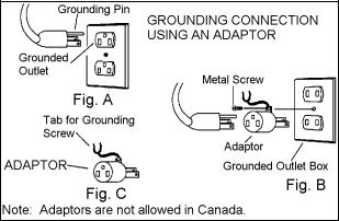
GROUNDING INSTRUCTIONS:
This appliance must be grounded. If it should malfunction or break down, grounding provides a path of least resistance for electric current to reduce the risk of electric shock. This appliance is equipped with a cord having an equipment-grounding conductor and grounding plug. The plug must be inserted into an appropriate outlet that is properly installed and grounded in accordance with all local codes and ordinances.
This appliance is for use on a nominal 120-volt circuit, and has a grounded plug that looks like the plug in “Fig. A”. A temporary adaptor that looks like the adaptor in “Fig. C” may be used to connect this plug to a 2-pole receptacle as shown in “Fig. B”, if a properly grounded outlet is not available. The temporary adaptor should be used only until a properly grounded outlet (Fig. A) can be installed by a qualified electrician. The green colored rigid ear, lug, or wire extending from the adaptor must be connected to a permanent ground such as a properly grounded outlet box cover. Whenever the adaptor is used, it must be held in place by a metal screw.
GROUNDING INSTRUCTIONS
Improper connection of the equipment-grounding conductor can result in a risk of electric shock. Check with a qualified electrician or service person if you are in doubt as to whether the outlet is properly grounded. Do not modify the plug provided with the appliance - if it will not fit the outlet, have a proper outlet installed by a qualified electrician.
86039020 VOYAGER E 08/20/07 |
2-3 |
NOTES
2-4 |
86039020 VOYAGER E 08/20/07 |
|
|
TECHNICAL SPECIFICATIONS |
|
|
|
ITEM |
DIMENSION/CAPACITY |
|
Electrical |
115V, 15A, 60HZ |
|
Electric Propelling Motor |
(1)-1/4 hp DC (186 watts) with variable speed forward and |
|
|
|
reverse, with safety shut-off. |
Drive System |
Belt Drive w/ manual clutching mechanism. Operating speed” |
|
|
|
0-100 ft/min (30 m/min) |
Electric Vacuum Motor |
(1)-3 stage, 1 hp (746 watts), 99 cfm (2.80 m³/min.) |
|
Waterlift |
117” (397 cm). Electric float shut-off. |
|
Electric Brush Motor |
(1)-0.4 hp (298 watts) permanent magnet, DC. |
|
Brush Speed |
1000 RPM |
|
Solution Pump |
100 psi, diaphragm style pump |
|
Solution Capacity |
40 Gallons (151 ltr) |
|
Recovery Capacity |
35 Gallons (132 ltr) |
|
Vacuum Shoe |
28” (71 cm) wide, cast aluminum, adjustable floating and |
|
|
|
pivoting. |
Wheels |
|
|
- |
Front (2) |
10” dia. (25 cm) by 2.5” wide (6.4 cm) |
- |
Rear (2) |
4” dia. (10cm) casters |
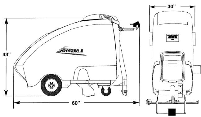
Dimensions – Weight (empty) |
280 lbs. (127 kg) |
|
Dimensions |
|
|
- |
Length |
60” (152 cm) |
- |
Storage Position |
52” (132 cm) |
Dimensions - Height |
43” (109 cm) |
|
Dimensions - Width |
30” (76 cm) |
|
|
SIDE VIEW |
TOP VIEW |
86039020 VOYAGER E 08/20/07 |
3-1 |

COMPONENTS
4
1
16
5
7
6
3
11
9
10 
1.Brush Height Adjustment – Raises and adjusts the height of the brush.
2.Vac Shoe Lift Lever – Lifts the vac shoe up or down and switches vac motor off and on. 2nd slot for accessory tool use.
3.Electrical Power Cord
4.Main Power Switch – Turns On and Off the machine and pump.
25. Drive Handle Control and Connection –
This is where the handle controls are connected electrically to the drive.
6. |
Drive Motor Circuit Breaker – 3 amp, |
|
13 |
protects the drive motor mechanism. |
|
|
||
7. |
Vac Motor Circuit Breaker – 13 amp, |
|
15 |
protects the vacuum motor. |
|
Brush Motor Circuit Breaker – 4 amp, |
||
8. |
||
|
protects the brush motor. |
|
9. |
Accessory Tool Hookup – Used for |
|
|
various auxiliary cleaning tools. |
810. Hour Meter – Displays the running time for the machine.
1211. Belt Tension Handle – Puts machine into “Dirve” or “Neutral” engagement.
1412. Data Plate Label – Shows serial number, model and voltage information.
13.Height Adjustment Handle – Adjusts the handle height for comfortable operation.
14.Accessory Tool Hose Attachment – To use accessory tool, remove hose from vac shoe and attach to accessory tool adapter.
15.Sight fill tube.
16.Drain hose.
3-2 |
86039020 VOYAGER E 08/20/07 |
1
2
3 4
DRIVE CONTROLS
1.The speed the machine will travel is regulated by knob located on the controls which are found on the main handle. Turn the knob to the right to increase the speed of the machine.
2.Squeezing one or both of the control levers will propel the machine forward at the selected speed.
3.Releasing both control levers will stop the machine.
4.Pressing forward on the levers moves the machine backwards at the selected speed
FILLING THE VOYAGER
NOTE: If a bucket is used to fill the tank, be sure it is clean.


 DO NOT PUT
  DEFOAMER, SOLVENTS, SPOTTER OR PRE-SPRAY
CHEMICALS IN THE SOLUTION TANK.
CHEMICALS |
OPERATION |
|
|
SUITABLE CHEMICALS |
NON-COMPATIBLE |
|
CHEMICALS |
Alkalis |
Aldehydes |
Detergents |
Aromatic Hydrocarbons |
Hydroxides |
SP Butyls |
Soaps |
Carbon Tetrachloride |
Vinegar |
Chlorox* |
D-Limonene@ |
Chlorinated Bleaches |
@When properly |
Chlorinated Hydrocarbons |
diluted |
Lysol* |
* Registered |
Methyl Ethel Ketone |
Trademark |
(MEK) |
|
Perchorethylene (perc) |
|
Phenolics |
|
Trichlorethyelene |
NOTE: The internal parts of the pump used in the extractor are suitable for use with most carpet cleaning chemicals. However, it is susceptible to chemical attack from cleaning substances, such as hydrocarbon solvents and chlorinated bleaches. These noncombustible materials are not of the type normally used for carpet cleaning.
86039020 VOYAGER E 08/20/07 |
3-3 |

OPERATION
1. Remove dome lid.
2. Add water.
3. Add cleaning chemical.
4. Replace dome lid.
3-4 |
86039020 VOYAGER E 08/20/07 |

OPERATION
1. Remove cord from storage bin.
STEP 1
2. Adjust handle to operating position.
ADJUST
3. Plug cord into grounded outlet.
4. Turn Main Power Switch “ON” – “I”
86039020 VOYAGER E 08/20/07 |
3-5 |
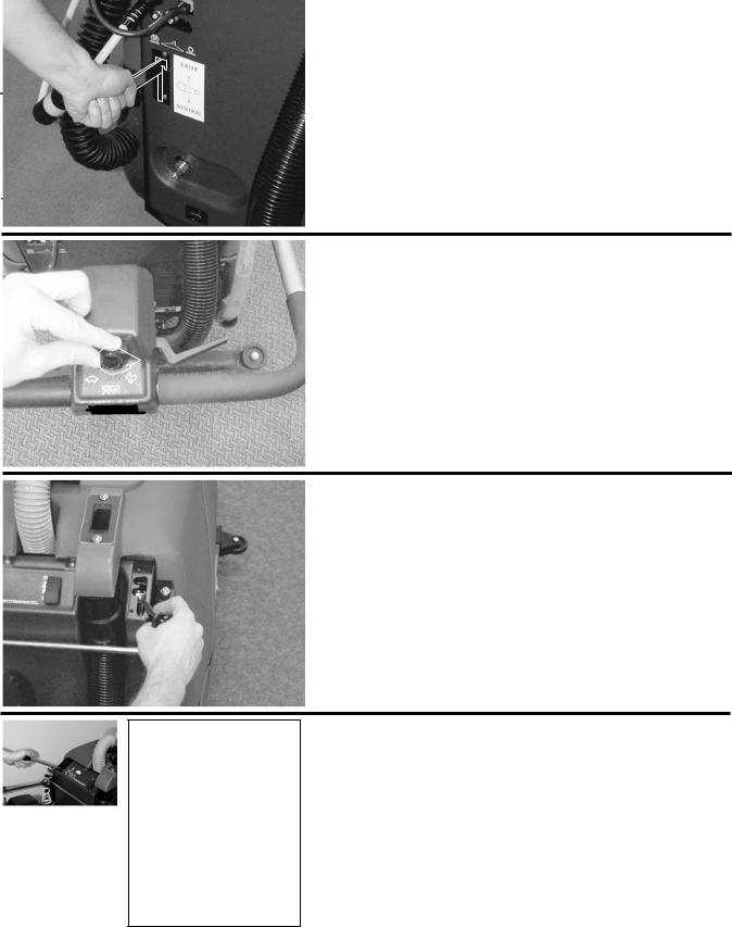
OPERATION
5. Lift belt tension handle to “Drive” position.
6. Adjust speed control knob to desired speed.
7. Turn vacuum motor on by lowering right hand lever all the way down.
INCORRECT
8. Lower brush to correct setting using left hand lever, listening for low hum of brush.
CORRECT
3-6 |
86039020 VOYAGER E 08/20/07 |
 Loading...