

Page 1
I
ALTERNATORI AUTOREGOLATI SERIE ECO-ECP
ISTRUZIONI PER L’USO E LA MANUTENZIONE
GB
SELF- REGULATING ALTERNATORS SERIES ECO-ECP
OPERATING AND MAINTENANCE INSTRUCTIONS
F
ALTERNATEURS AUTO - REGULES SERIE ECO-ECP
MANUEL D’INSTRUCTION ET DE MAINTENANCE
D
SELBSTREGELNDER GENERATOR SERIE ECO-ECP
BETRIEBS-UND WARTUNGSANLEITUNG
E
ALTERNADORES AUTOREGULADOS SERIE ECO-ECP
INSTRUCCIONES PARA USO Y MANTENIMIENTO
ECO
ECP
Page 2
INDICE
PAG
INDEX
DESCRIZIONE MACCHINA
PREMESSA
IDENTIFICAZIONE MACCHINA
VERIFICA ALLA CONSEGNA
PRESCRIZIONI DI SICUREZZA
TRASPORTO E IMMAGAZZINAMENTO
ACCOPPIAMENTO MECCANICO
ACCOPPIAMENTO ELETTRICO
AVVIAMENTO E ARRESTO
PULIZIA E LUBRIFICAZIONE
MANUTENZIONE
ANOMALIE E RIMEDI
PARTI DI RICAMBIO
TAVOLE
DIMENSIONI D’INGOMBRO
APPENDICE DSR
APPENDICE DER1
GARANZIA
CENTRI DI ASSISTENZA
DESCRIZIONE
MACCHINA
2 ÷ 3
4 ÷ 5
4 ÷ 5
4 ÷ 5
4 ÷ 13
14 ÷ 17
16 ÷ 21
22 ÷ 29
30 ÷ 31
30 ÷ 31
30 ÷ 53
54 ÷ 55
56 ÷ 58
59 ÷ 74
75 ÷ 80
81 ÷ 84
85 ÷ 90
91
92 ÷ 96
MACHINE DESCRIPTION
INTRODUCTION
MACHINE IDENTIFICATION
INSPECTION ON DELIVERY
SAFETY REQUIREMENTS
TRANSPORT AND STORAGE
MECHANICAL COUPLING
ELECTRICAL CONNECTIONS
STARTING AND STOPPING OPERATIONS
CLEANING AND LUBRICATION
MAINTENANCE
DEFECTS AND REMEDIES
SPARE PARTS
TABLES
OVERALL DIMENSIONS
DSR APPENDIX
DER1 APPENDIX
WARRANTY
AFTER-SALES SERVICE
MACHINE
DESCRIPTION
I generatori della serie ECO-ECP sono
autoregolati, brushless a 2 e 4 poli.
Hanno induttore rotante provvisto di
gabbia di smorzamento e indotto fisso a
cave inclinate.
Gli avvolgimenti sono a passo
raccorciato per ridurre il contenuto
armonico.
I generatori sono costruiti in conformità
alle direttive CEE 2006/42, 2006/95,
2004/108 e relative modifiche, alle
norme CEI 2-3, EN 60034-1, IEC 34-1,
VDE 0530, BS4999-5000, CAN/CSAC22.2 N°14 - N°100.
Le prove per la verifica della
compatibilita’ elettromagnetica sono
state eseguite nelle condizioni prescritte
dalle norme, con il neutro collegato a
terra.
Esecuzioni in accordo ad altre
specifiche possono essere eseguite su
richiesta del cliente.
La struttura meccanica, sempre molto
robusta, consente un facile accesso ai
collegamenti e permette di eseguire le
verifiche nelle diverse parti altrettanto
facilmente.
La carcassa e’ realizzata in acciaio, gli
scudi in ghisa, l’albero in acciaio C45
con ventola calettata.
Il grado di protezione e’ IP21 (a
richiesta e’ possibile realizzare un grado
di protezione superiore).
Gli isolamenti sono eseguiti in classe H,
le impregnazioni con resine epossidiche
per le parti rotanti e trattamenti
sottovuoto per le parti di piu’ elevata
tensione, quali gli statori (a richiesta
trattamenti speciali).
ECO-ECP 2 and 4 pole alternators are
brushless, self-regulating and
incorporate a rotating inductor with
damper cage winding and a fixed stator
with skewed slots.
The stator windings have a shortened
pitch to reduce the harmonic content of
the output waveform.
The alternators are made in compliance
with the 2006/42, 2006/95, 2004/108
CEE directives and their amendments,
and the CEI 2-3, EN 60034-1, IEC 34-1,
VDE 0530, BS4999-5000, CAN/CSAC22.2 N°14 -N°100 regulations.
Tests to verify the electromagnetic
compability have been carried out in the
foreseen conditions by the standards
with the neutral connected to the earth.
On customer’s request alternators can
be manufactured according to different
specifications.
The robust mechanical construction
gives good access to the generator
output connections, and allows the user
to inspect the various components with
ease.
The casing is made of steel, the shields
of cast iron, and the shaft of C45 steel
and it has a keyed fan.
The mechanical protection level meets
standard IP21 (upon request higher
levels of protection can be supplied).
Insulation materials meet Class H requirements, and all rotating components
are epossy resins impregnated; higher
voltage parts, such as the stators, are
vacuum-treated (special treatments are
available on request).
2
ECO-ECP MANUAL September 2012 revision 32
Page 3
INDEX
INDICE INHALT
DESCRIPTION DE LA MACHINE
INTRODUCTION
IDENTIFICATION ALTERNATEUR
VERIFICATION A LA LIVRAISON
PRESCRIPTIONS DE SECURITE
TRANSPORT ET STOCKAGE
ACCOUPLEMENT MECANIQUE
RACCORDEMENT ELECTRIQUE
DEMARRAGE ET ARRET
ENTRETIEN ET LUBRIFICATION
MAINTENANCE
ANOMALIES ET REPARATIONS
PIECES DE RECHANGE
TABLEAUX
ENCOMBREMENT
APPENDICE DSR
APPENDICE DER1
GARANTIE
CENTRES D’ASSISTENCE
MASCHINENBESCHREIBUNG
VORWORT
MASCHINENIDENTIFIKATION
ÜBERPRÜFUNG BEI LIEFERUNG
SICHERHEITSVORSCHRIFTEN
TRANSPORT UND LAGERUNG
MECHANISCHER ANSCHLUß
ELEKTRISCHER ANSCHLUß
ANTRIEB UND STILLSETZUNG
REINIGUNG UND SCHMIERUNG
WARTUNG
STÖRUNGEN UND ABHILFE
ERSATZTEILE
TABELLEN
BAUMASSE
DSR NACHTRAG
DER1 NACHTRAG
GARANTIE / GEWÄHRLEISTUNG
SERVICE-CENTER
DESCRIPCION MAQUINA
ACLARACION
IDENTIFICACION MAQUINA
CONTROL A LA ENTREGA
PRECAUCIONES DE SEGURIDAD
TRANSPORTE Y DEPOSITO
ACLOPAMIENTO MECANICO
CONEXION ELECTRICO
ARRANQUE Y PARADA
LIMPIEZA Y LUBRIFICACION
MANTENIMIENTO
PROBLEMAS Y SOLUCIONES
PARTES DE REPUESTO
TABLAS
DIMENSIONES MAXIMAS
APENDICE DSR
APENDICE DER1
GARANTIA
CENTROS DE ASISTENCIA
DESCRIPTION DE
LA MACHINE
Les alternateur de série ECO-ECP sont
auto-régulés, sans bague ni balai à 2 et
4 pôles.
Ils sont à inducteurs tournants avec
cage d’amortissement et stators à
encoches inclinées. Les bobinages sont
à pas raccourcis afin de réduire le taux
d’harmoniques. Les alternateurs sont
construits en conformité aux directives
CEE 2006/42, 2006/95, 2004/108 et
leurs modifications, aux normes CEI 23, EN 60034-1, IEC 34-1, VDE 0530,
BS4999-5000, CAN/CSA-C22.2 N°14 N°100.
Les essais pour la verification de la
compatibilite electromagnetique ont eté
executés dans les conditions prescrites
par les normes avec le neutre connecté
à la masse. Les exécutions en accord
avec d’autres spécifications peuvent
être suivies sur demande du client.
La structure mécanique, toujours trés
robuste, permet un accés facile aux
raccordements et permet les
vérifications des autres parties trés
facilement.
La carcasse est en acier, les flasques
en fonte, l’arbre est en acier C45 avec
ventilateur claveté. Le grade de
protection est IP21 (sur demande, il est
possible de réaliser un grade de
protection supérieure).
Les isolements sont de la classe H, les
imprégnations en vernis epoxy pour les
parties tournantes et les parties plus
élevées en tension comme les stators
sont imprégnées sous vide et pression
(sur demande, nous pouvons exécuter
des traitements spéciaux).
MASCHINEN
BESCHREIBUNG
Die 2 und 4 poligen Generatoren der Serie
ECO-ECP sind selbstregelnd und bürstenlos.
Sie besitzen einen mit einem Dämpfungskäfig
ausgestatteten, rotierenden Anker und einen
fest eingebauten Stator mit schrägen Nuten.
Die Wicklungen sind im Schritt verkürzt, um
den harmonischen Gehalt der Wellenform zu
reduzieren.
Die Generatoren sind in Ubereinstimmung
mit den Bestimmungen CEE 2006/42 sowie
mit 2006/95 und 2004/108 und deren
entsprechenden Änderung,en und den
Normen CEI 2-3, EN 60034-1, IEC 34-1,
VDE 0530, BS4999-5000, CAN/CSA-C22.2
N°14 - N°100, hergestellt. Die
elektromagnetische Verträglichkeitsprüfungen
wurden, wie in den Normen
vorgeschriebenen mit geerdetem Sternpunkt
ausgeführt. Ausführungen, die anderen als
den angegebenen Spezifikationen entsprechen
sollen, können auf Kundenanfrage hergestellt
werden.
Die mechanische, sehr widerstandsfähige,
robuste Struktur ermöglicht leichten Zugang
zu den Verbindungen und Anschlüssen und
erlaubt eine ebenso leichte Kontrolle der
verschiedenen Teile. Das Gehäuse besteht
aus Stahl, die (Schutz) schilde aus Gußeisen,
die Welle aus C45-Stahl mit aufgezogenem
Lüfterrad. Die Schutzklasse ist IP21 (auf
Anfrage kann auch eine hohere Schutzklasse
realisiert werden).
Die Isolierungen entsprechen der Klasse H,
die Imprägnierungen erfolgen mit Epoxidharzen für die drehbaren Teile, bzw, durch
Vakuumverfahren für die Teile, die erhöhter
Spannung ausgesetzt sind, wie z.B. Ständer
(auf Anfrage auch Sonderverfahren möglich).
DESCRIPCION
MAQUINA
Los generadores serie ECO-ECP son
auto-regulados, brushless a 2 y 4 polos.
Possen inductor rotante con jaula de
atenuación e inducido fijo con canaletas
inclinadas.
Los bobinados son a paso recortado
para reducir el contenido armónico.
Los generadores están construidos en
conformidad a las directivas CEE
2006/42, 2006/95, 2004/108 y sus
modÍficas, normas CEI 2-3, EN 600341, IEC 34-1, VDE 0530, BS 49995000, CAN/CSA-C22.2 N°14 - N°100.
Las pruebas de conformidad a la
compatibilidad electromagnetica fueron
realizadas en las condiciones indicadas
por las normas en decir con el neutro
conectado a tierra. Construcciones de
acuerdo con otras especÍficas podrán
ser realizadas bajo pedido del cliente.
La estructura mecánica, siempre de
gran consistencia, permite un fácil
acceso a los conexionados, como asÍ
también un control de las diferentes
partes de la misma.
La carcasa está construida en acero,
las tapas en fundición, el eje en acero
C45 con ventilador acoplado. El grado
de protección es IP21 (a pedido es
posible realizar un grado de protección
superior).
Los aislantes son en clase H, las partes
rotantes son impregnadas con resinas
epoxidicas con tratamiento en vacío
para las partes que trabajan a mayor
tensión, como son los estatores (a
pedido tratamientos especiales).
3
ECO-ECP MANUAL September 2012 revision 32
Page 4
PREMESSA
INTRODUCTION
I generatori della serie ECO-ECP, rispondono
alle direttive CEE 2006/42, 2006/95,
2004/108 e relative modifiche; pertanto non
presentano pericolo per l’operatore, se
installati, usati, manutenuti secondo le
istruzioni fornite dalla Mecc Alte e a
condizione che i dispositivi di sicurezza siano
tenuti in perfetta efficienza.
Per questa ragione occorre attenersi scrupolosamente alle istruzioni indicate in questo
manuale.
E’ vietata qualsiasi riproduzione di questo
manuale.
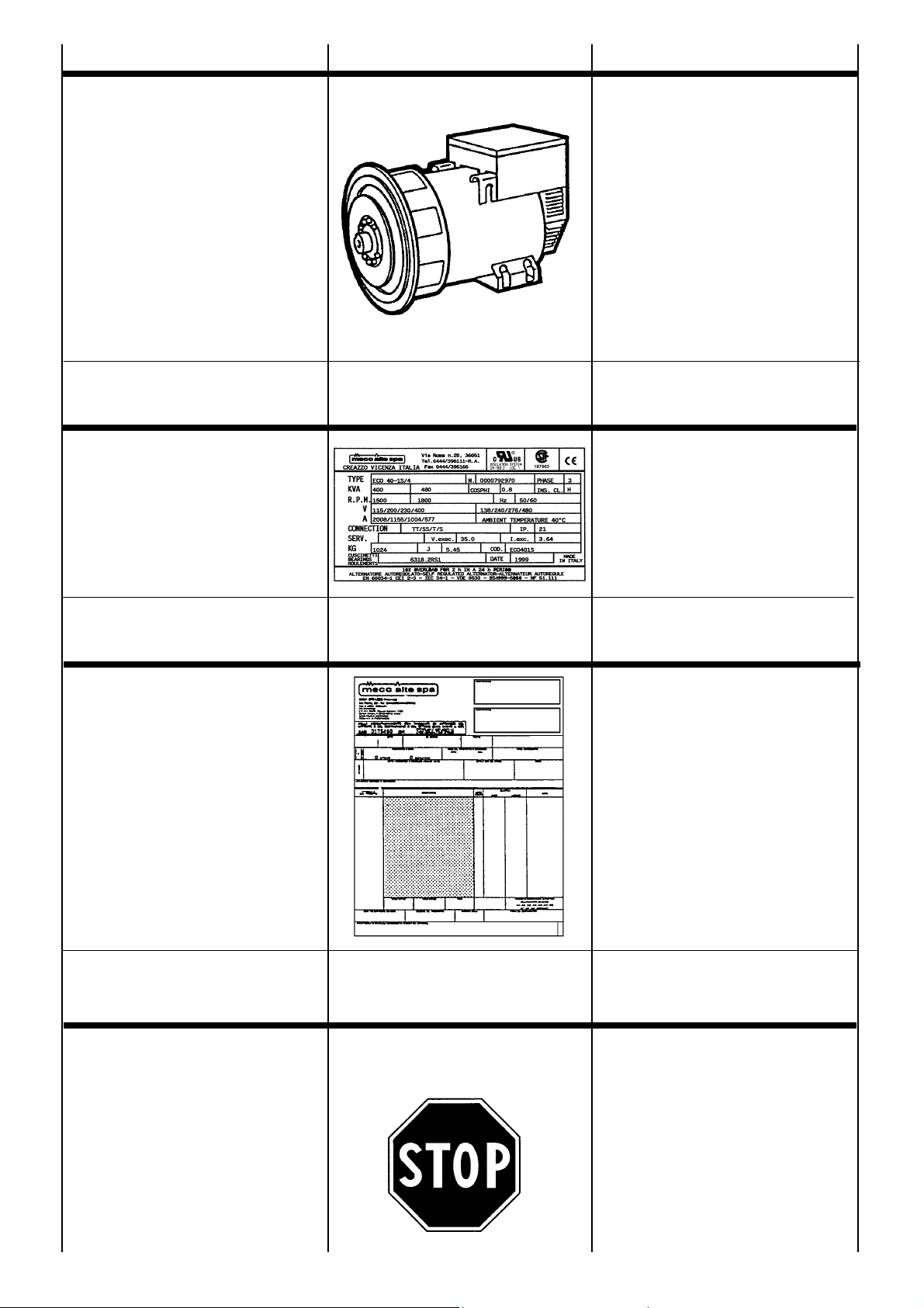
IDENTIFICAZIONE
MACCHINA
Per qualsiasi comunicazione con la
Mecc Alte o con i centri di assistenza
autorizzati, citare sempre il tipo e il
codice del generatore.
The ECO-ECP alternators comply with the
EEC 2006/42, 2006/95, 2004/108 directives
and their amendments; therefore they pose
no danger to the operator if they are installed,
used and maintained according to the
instructions given by Mecc Alte and provided
the safety devices are kept in perfect working
conditions.
Therefore a strict observance of these
instructions is required.
Any reproduction of this manual is forbidden.
MACHINE
IDENTIFICATION
Always indicate the generator type and code
when contacting Mecc Alte or the authorized
after-sales service centres.
VERIFICA ALLA
CONSEGNA
Alla consegna del generatore controllare
con la bolla di accompagnamento che
non ci siano danni o parti mancanti; nel
caso informare immediatamente lo
spedizionere, l’assicurazione, il rivenditore
o la Mecc Alte.
PRESCRIZIONI DI
SICUREZZA
Prima di qualsiasi intervento di pulizia, lubrificazione o manutenzione assicurarsi che il
motore primario a cui e’ collegato il generatore
non sia in funzione, ma fermo e isolato dalle
sue fonti di energia.
Per fermare il generatore occorre seguire
scrupolosamente la procedura di arresto del
sistema di trascinamento; il generatore non e’
previsto di Stop/Emergenza, ma si arresta
istantaneamente in relazione al sistema di
arresto predisposto dall’installatore.
INSPECTION ON
DELIVERY
When the alternator is delivered, check that
unit conforms with the delivery note and
ensure that there are no damaged or
defective parts; should there be any, please
inform the forwarding agent, the insurance
company, the seller or Mecc Alte
immediately.
SAFETY
REQUIREMENTS
Before any cleaning, lubrication or
maintenance operation, ensure that the
generator is stationary and disconnected from
the power supply.
When stopping the generator, ensure the
compliance with the procedures for stopping
the prime mover.
The generator, in fact, has no Emergency
Stop, but is controlled by the device arranged
by the installer.
4
ECO-ECP MANUAL September 2012 revision 32
Page 5
INTRODUCTION VORWORT ACLARACION
Les alternateurs de la série ECO-ECP
répondent aux directives CEE 2006/42,
2006/95, 2004/108 et leurs modifications.
Toutefois, ils ne présentent aucun danger
pour l’utilisateur si l’installation, l’utilisation, les
manutentions suivent les instructions fournies
par Mecc Alte et à condition que les dispositifs
de protection soient tenus en parfait état de
marche.
Pour cette raison, il faut se conformer
scrupuleusement aux instructions indiquées
dans ce manuel.
Toute reproduction de ce manuel est interdit.
IDENTIFICATION
DE LA MACHINE
Pour toute demande auprès de Mecc Alte ou
auprès des centres agrées autorisés, citer
toujours le type et le code de l’alternateur.
Die Generatoren entsprechen den EG Bestimmugen 2006/42, 2006/95, 2004/108
und deren entsprechenden Änderungen; aus
diesem Grunde stellen sie keinerlei Gefahr für
den Bediener dar, sofern sie in
Übereinstimmung mit den von Mecc Alte
vorgeschriebenen Anweisungen installiert,
verwendet und gewartet werden und unter
der Bedingung, daß die Schutzvorrichtungen
stets in einem voll funktionstüchtigen Zustand
gehalten werden.
Aus den oben genannten Gründen ist es
erforderlich, sich streng an die in diesem
Handbuch angegebenen Anweisungen zu
halten.
Jegliche Form der Verbreitung und
Reproduktion dieses Handbuchs ist verboten.
MASCHINENIDENTIFIKATION
Für Mitteilungen an Mecc Alte oder an die
autorisierten Service-Zentralen, ist der
Generatorentyp und der Code anzugeben.
Los generadores de la serie ECO-ECP,
responden a las directivas CEE 2006/42,
2006/95, 2004/108 y a sus respectivas
modificaciones, por lo tanto no se presentan
peligros para el operador, si instalados,
usados y mantenidos según las instrucciones
dadas por la Mecc Alte y con la condición que
los dispositivos de seguridad sean
mantenidos en una condición de perfecta
eficiencia.
Por esta razón es necesario adecuarse a la
perfección a las instrucciónes indicadas en
este manual.
Se prohibe la reproducción total o parcial de
este manual.
IDENTIFICACION
MAQUINA
Para cualquier tipo de comunicación con la
Mecc Alte o con los centros de reparación
autorizados, indicar siempre el tipo y el código
del generador.
VERIFICATION
A LA LIVRAISON
A la livraison de l’alternateur, contrôler avec le
bon de livraison qu’il n’y a aucun dommage
ou de pièces manquantes; si c’est le cas,
informer immédiatement l’expéditeur,
l’assureur, le revendeur ou Mecc Alte.
PRESCRIPTIONS
DE SECURITE
Avant une quelconque intervention de
nettoyage, lubrification ou manutention, le
moteur avec lequel est accouplé l’alternateur
ne doit pas être en fonctionnement mais
coupé de ses sources d’énergie.
Pour arrêter un alternateur, il faut suivre
scrupuleusement la procédure d’arrêt du
système d’entraînement, l’alternateur n’est
pas pourvu d’arrêt d’urgence, mais il s’arrête
instantanément en fonction du système
d’arrêt prévu par l’installateur.
ÜBERPRÜFUNG
BEI LIEFERUNG
Bei Lieferung des Generators ist anhand des
Lieferscheins dieser auf Schäden, bzw. auf
fehlende Teile hin zu überprüfen; in diesem
Falle sind der Spediteur, die Versicherung,
der Wiederverkäufer oder Mecc Alte
umgehend darüber zu informieren.
SICHERHEITSVORSCHRIFTEN
Vor jedem Eingriff für Reinigung, Schmierung
oder Wartung, muß der Hauptmotor, an den
der Generator angeschlossen ist, außer
Betrieb gesetzt werden; er muß stillstehen
und von seinen Energiequellen isoliert
werden.
Um dem Generator zu stoppen, ist es
erforderlich genauestens das Abstellverfahren
für das Zugsystem einzuhalten; der Generator
ist nicht mit einem Sicherheitsabschalter
(“NOTAUS”) versehen, sondern er stoppt
unmittelbar in Abhängigkeit von dem
Abschaltsystem, das vom Hersteller
vorgesehen ist.
5
CONTROL A LA
ENTREGA
A la entraga del generador, controlar junto
con la factura que no existan defectos o
piezas faltantes; en caso contrario informar
inmediatamente la empresa de transportes,
la compañia de seguros, el revendedor o la
Mecc Alte S.p.A.
PRECAUCIONES
DE SEGURIDAD
Antes de cualquier tipo de operación de
limpieza, lubrificación o mantenimiento, el
motor primario al cual está acoplado el
generador no debe estar en funcionamiento,
el mismo deberá estar inmóvil y aislado de
sus fuentes de energía.
Para detener el generador es necesario
seguir escrupolosamente los procedimientos
de detención del sistema de arrastre; el
generador no posee un Stop/Emergencia,
pués el mismo se detiene instantaneamente
en función del sistema de stop preparado por
el instalador.
ECO-ECP MANUAL September 2012 revision 32
Page 6
PRESCRIZIONI
DI SICUREZZA
SAFETY
REQUIREMENTS
Durante la consultazione del presente
manuale d’uso e manutenzione troverete
alcuni simboli; questi hanno un preciso
significato qui di seguito illustrato.
SIMBOLOGIA CONVENZIONALE
E SUA DEFINIZIONE
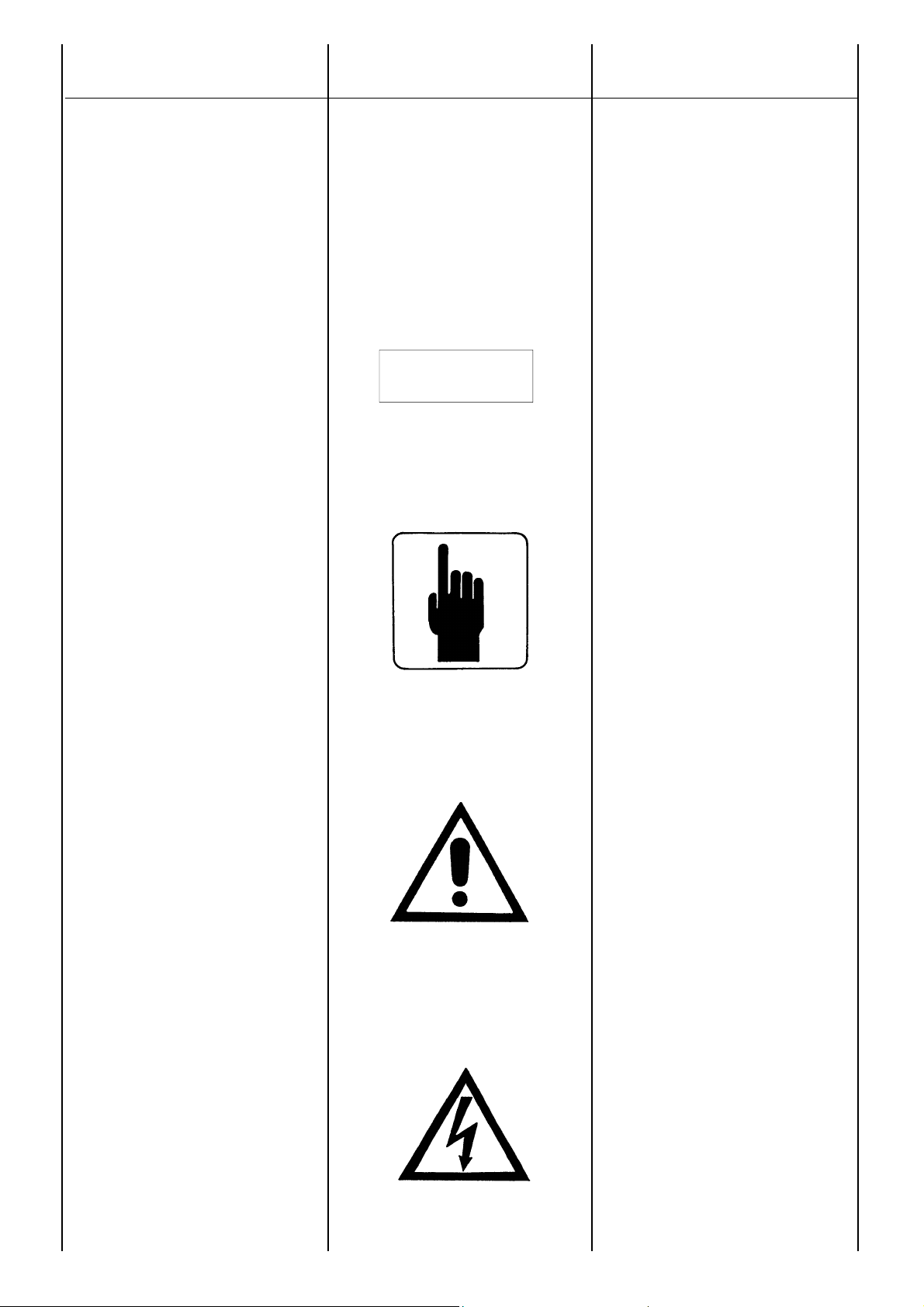
IMPORTANTE
Segnala al personale interessato che
l’operazione descritta presenta un
rischio che può avere come
conseguenza un danno alla
macchina, se non effettuata nel
rispetto delle normative di sicurezza.
ACCORTEZZA
Segnala al personale interessato che
l’operazione descritta presenta un
rischio che può avere come
conseguenza un danno alla macchina
e/o lesioni al personale stesso, se
non effettuata nel rispetto delle
normative di sicurezza.
AVVERTIMENTO
Segnala al personale interessato che
l’operazione descritta presenta un
rischio che può avere come
conseguenza lesioni gravi o morte,
se non effettuata nel rispetto delle
normative di sicurezza.
PERICOLO
Segnala al personale interessato che
l’operazione descritta presenta un
rischio immediato che ha come
conseguenza lesioni gravi o morte,
se non effettuata nel rispetto delle
normative di sicurezza.
IMPORTANTE
IMPORTANT
WICHTIG
In consulting this use and maintenance
manual, you will find several symbols, which
have a specific meaning, as illustrated below.
CONVENTIONAL SYMBOLS AND
SYMBOL DESCRIPTION
IMPORTANT
This symbol warns the personnel
concerned that the described
operation may cause damages to the
machine if it is not carried out
according to the safety standards.
CAUTION
This symbol warns the personnel
concerned that the described
operation may cause damages to the
machine and/or injures to the
personnel if it is not carried out
according to the safety standards.
WARNING
This symbol warns the personnel
concerned that the described
operation may cause serious injuries
or death to the personnel if it is not
carried out according to the safety
standards.
DANGER
This symbol warns the personnel
concerned that the described
operation may immediately cause
serious injuries or death to the
personnel if it is not carried out
according to the safety standards.
6
ECO-ECP MANUAL September 2012 revision 32
Page 7

PRESCRIPTIONS
DE SECURITE
SICHERHEITS
VORSCRIFTEN
PRECAUCIONES
DE SEGURIDAD
Lors de la consultation de ce manuel
d’instruction et de mantenance, vous
trouverez quelques symboles; ceux-ci ont une
signification précise.
SYMBOLES CONVENTIONNELS
ET DEFINITIONS
IMPORTANT
Ce symbole avertit l’utilisateur que
l’operation décrite peut causer des
dommages à la machine si elle n’est
pas effectuée dans le respect des
normes de securité.
MISE EN GARDE
Ce symbole avertit l’utilisateur que
l’operation décrite peut causer des
dommages à la machine et/ou des
lésions graves à l’utilisateur, si elle
n’est pas effectuée dans le respect
des normes de securité.
AVVERTISSEMENT
Ce symbole avertit l’utilisateur que
l’operation décrite présente un risque
qui peut avoir comme consèquence
des lésions graves ou même la mort,
si elle n’est pas effectuée dans le
respect des normes de securité.
AVERTISSEMENT
Ce symbole avertit l’utilisateur que
l’operation décrite présente un risque
immédiat qui peut avoir comme
consèquence des lésions graves ou
même la mort, si elle n’est pas
effectuée dans le respect des normes
de securité.
Beim Lesen dieser Gebrauchs- und
Wartungsanleitung finden Sie einige
Symbole zu finden; diese habe eine ganz
genaue Bedeutung, die im Folgenden
ALLGEMEIN ÜBLICHE SYMBOLIK
UND IHRE DEFINITION
WICHTIG
Signalisieren Sie dem zuständigen
Personal, daß die beschriebene
Arbeit ein Risiko darstellt, welches
Schäden an der Maschine zur Folge
haben kann; falls die Arbeit nicht
unter voller Beachtung der
Sicherheitsvorschriften erfolgt.
HINWEIS
Signalisieren Sie dem zuständigen
Personal, daß die beschriebene
Arbeit ein Risiko darstellt, welches
Schäden an der Maschine und/oder
Verletzungen des Personales selbst
zur Folge haben kann; falls die
Arbeit nicht unter voller Beachtung
der Sicherheitsvorschriften erfolgt.
WARNHINWEIS
Dieses Symbol warnt das Personal,
daß die hier beschriebene Operation
eine eventuelle Gefahr darstellt, die
ernste Verletzungen oder den Tod
als Konsequenz zur Folge haben
kann, wenn auszuführende Arbeit
nicht nach den vorgeschriebenen
Sicherheitsnormen durchgeführt
wird.
GEFAHR
Dieses Symbol warnt das Personal,
daß die hier beschriebene Operation
eine sofortige Gefahr darstellt, die
ernste Verletzungen oder den Tod
als Konsequenz zur Folge haben
kann, wenn auszuführende Arbeit
nicht nach den vorgeschriebenen
Sicherheitsnormen durchgeführt
wird.
Durante la consultaciòn de el presente
manual uso y manutention, aquìy allì hallerà
algunes simbolos; Esos ont une preciso
significado.
SIMBOLOGIA CONVENCIONAL Y
SUAS DEFINICION
IMPORTANTE
Signa a el personal interesado que el
operation descrita presenta, une
riesgo que puede hacer como
consecuencia une daño a la
maquina, se no efectuada en el
respecto de les normatives de
securidad.
AGUDEZA
Signa a el personal interesado que el
operation descrita presenta, une
riesgo que puede hacer como
consecuencia une daño a la maquina
y/ou lésiones a el persoanl mismo,
se no efectuada en el respecto de les
normatives de securidad.
ADVERTIMIENTO
Señales a los personales interesado
que la operación descrita introduce
un riesgo que él pueda tener como
lesiones o muertos serios de la
consecuencia, si no está realizado
en el respecto de lles normatives de
securidad.
PELIGRO
Señales a los personales interesado
que la operación descrita introduce
un riesgo inmediato que tenga como
lesiones o muertos seriosn de la
consecuencia, si no está realizado
en el respecto de les normatives de
securidad.
7
ECO-ECP MANUAL September 2012 revision 32
Page 8
PRESCRIZIONI
DI SICUREZZA
SAFETY
REQUIREMENTS
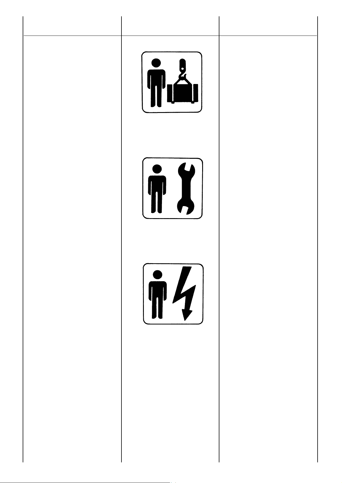
ADDETTO ALLA MOVIMENTAZIONE
Identifica il tipo di operatore a cui è
riservato l’intervento trattato.
Questa qualifica presuppone una piena
conoscenza e comprensione delle
informazioni contenute nel manuale
d’uso del costruttore oltre che
competenze specifiche dei mezzi di
sollevamento, dei metodi e delle
caratteristiche d’imbragatura e della
movimentazione in sicurezza.
MANUTENTORE MECCANICO
Identifica il tipo di operatore a cui è
riservato l’intervento trattato.
Questa qualifica presuppone una piena
conoscenza e comprensione delle
informazioni contenute nel manuale
d’uso del costruttore oltre che
competenza specifica per effettuare gli
interventi di installazione, regolazione,
manutenzione, pulizia e/o riparazione.
MANUTENTORE ELETTRICO
Identifica il tipo di operatore a cui è
riservato l’intervento trattato.
Questa qualifica presuppone una piena
conoscenza e comprensione delle
informazioni contenute nel manuale
d’uso del costruttore oltre che
competenza specifica per gli interventi
di natura elettrica di collegamento,
regolazione, manutenzione e/o
riparazione.
E’ in grado di operare in presenza di
tensione all’interno di armadi e
quadri elettrici.
Nel caso di interventi straordinari e su
autorizzazione scritta del servizio
assistenza rivolgersi ai centri autorizzati
Mecc Alte.
HANDLER
This symbol identifies the type of
operator in charge of the operation
described.
This qualification requires a complete
knowledge and understanding of the
information contained in the
manufacturer’s instruction manual as
well as specific skills about the hoisting
means, slinging methods and features
and safe handling procedures.
MECHANICAL SERVICE MAN
This symbol identifies the type of
operator in charge of the operation
described.
This qualification requires a complete
knowledge and understanding of the
information contained in the
manufacturer’s instruction manual as
well as specific skills necessary to
perform installation, adjustment,
maintenance, cleaning and/or repair
operations.
ELECTRICAL SERVICE MAN
This symbol identifies the type of
operator in charge of the operation
described.
This qualification requires a complete
knowledge and understanding of the
information contained in the
manufacturer’s instruction manual as
well as specific skills necessary to
perform electrical operations such as
connections, adjustment, maintenance
and/or repair.
The electrical service man must be
able to work even in case electrical
cabinets and panels are live.
In case of exceptional operations and
upon written request of servicing
operations please apply to Mecc Alte
authorized centers.
8
ECO-ECP MANUAL September 2012 revision 32
Page 9

PRESCRIPTIONS
DE SECURITE
SICHERHEITS
VORSCRIFTEN
PRECAUCIONES
DE SEGURIDAD
MANUTENTIONAIRE
Ce symbole identifie le type d’opérateur
en charge de l’intervention décrite.
Cette qualification suppose une pleine
connaisance et compréhension des
renseignements contenus dans le
manuel d’instruction du constructeur et
également des compétences spécif
ques sur les moyens de levage, des
méthodes et des caractéristiques des
harnais et de déplacement en toute
sécurité.
MECANICIEN
Ce symbole identifie le type d’opérateur
en charge de l’intervention décrite.
Cette qualification suppose une pleine
connaisance et compréhension des
renseignements contenus dans le
manuel d’instruction du constructeur
ainsi que les compétences spécifiques
pour effectuer les interventions
d’installation, réglages, manutention,
nettoyage et/ou réparation.
ELECTRICIEN
Ce symbole identifie le type d’opérateur
en charge de l’intervention décrite.
Cette qualification suppose une pleine
connaisance et compréhension des
renseignements contenus dans le
manuel d’instruction du constructeur
ainsi que les compétences spécifiques
pour les interventions de natures
électriques de connexion, réglage,
manutention, et/ou réparation.
L’opérateur électricien doit être en
mesure d’intervenir sur les armoires
et tableaux électriques.
En cas des interventiones inhabituelles
et sur autorisation écrite du service et
assistance s’addreser aux centres
autorisés Mecc Alte.
TRANSPORTBEAUFTRAGTER
Identifiziert den Personentyp, der mit
dem Transport bzw. der Bewegung der
Maschine beauftragt ist.
Diese Qualifikation setzt eine volle
Kenntnis und Verständnis der im
Bedienungshandbuch des Herstellers
enthaltenen Informationen voraus,
zusätzlich zu den spezifischen
Kompetenzen, was die Transport- und
Anhebemittel, die Eigenschaften der
Transportschlingen und der sicheren
Bewegung betrifft.
WARTUNGSFACHMANN MECHANIK
Identifiziert den Personentyp, der mit
der mechanischen Wartung beauftragt
ist. Diese Qualifikation setzt eine volle
Kenntnis und Verständnis der im
Bedienungshandbuch des Herstellers
enthaltenen Informationen voraus,
zusätzlich zu den spezifischen
Kompetenzen, was die Aufstellungs-,
Einstellungs-, Wartungs-, Reinigungsund/oder Reparaturarbeiten betrifft.
WARTUNGSFACHMANN ELEKTRIK
Identifiziert den Personentyp, der mit
der elektrischen Wartung beauftragt ist.
Diese Qualifikation setzt eine volle
Kenntnis und Verständnis der im
Bedienungshandbuch des Herstellers
enthaltenen Informationen voraus,
zusätzlich zu den spezifischen
Kompetenzen, was die Eingriffe
elektrischer Natur betrifft, wie:
Anschlüsse, Einstellung, Wartung und/
oder Reparaturen.
Er ist in der Lage, auch Arbeiten im
Inneren von Schaltschränken und tafeln auszuführen, wenn diese unter
Spannung stehen.
Im Fall von außergewöhnlichen
Eingriffen und Unklarheiten der
Beschreibung des techn. Services,
wenden Sie sich bitte an die
autorisierten Kundendienstzentren von
Mecc Alte.
APLICADO A LA MOVIMENTATION
Identifica el tipo de operador la cual es
reservado el intervenciòn tartado.
Esta calificaciòn presupone una llena
conocimiento y comprensiòn des
informaciònes contenidos en el manual
para uso de el constructor de la parte
de allà que competencia especificaciòn
des medios de leventamiento, des
métodos y des caracterìsticas de
barrachera y de movimentaciòn en
securidad.
MANUTENDOR MECANICO
Identifica el tipo de operador la cual es
reservado el intervenciòn tartado.
Esta calificaciòn presupone una llena
conocimiento y comprensiòn des
informaciònes contenidos en el manual
para uso de el constructor de la parte
de allà que competencia especificaciòn
por efectuar los intervenciònes de
instalaciòn, regulaciòn, manutenciòn,
limpieza y/ou reparaciòn.
MANUTENDOR ELÉCTRICO
Identifica el tipo de operador la cual es
reservado el intervenciòn tartado.
Esta calificaciòn presupone una llena
conocimiento y comprensiòn des
informaciònes contenidos en el manual
para uso de el constructor de la parte
de allà que competencia especificaciòn
por efectuar los intervenciònes de
natura electrica de coligamiento,
regulaciòn, manutenciòn, y/ou
reparaciòn.
Es en grado de trabajar en presencia
de tension a los interno des
armarios y cuadros electricos.
En caso de intervenciçnes
extraordinarios y su autorizaciòn
escritura du servicio assistencia
revolverse a los centros autorizado
Mecc Alte.
9
ECO-ECP MANUAL September 2012 revision 32
Page 10
PRESCRIZIONI
DI SICUREZZA
SAFETY
REQUIREMENTS
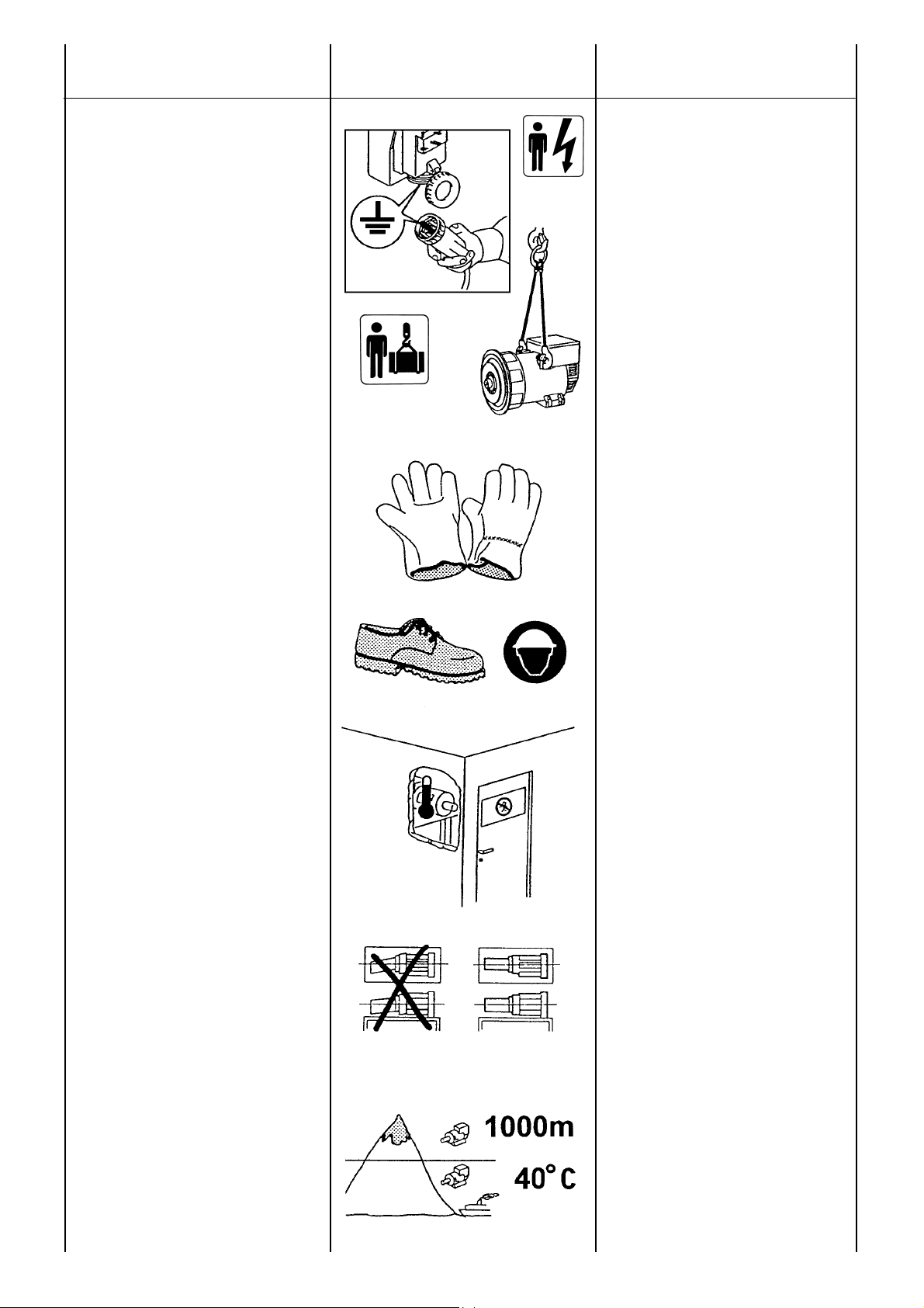
Al momento dell’installazione le norme
prevedono che il generatore sia collegato a
terra.
Per questa ragione assicurarsi che l’impianto
di messa a terra sia efficiente ed in
conformita’ con le direttive del paese dove il
generatore sara’ installato.
ATTENZIONE
L’INSTALLATORE FINALE E’
RESPONSABILE DELLA
PREDISPOSIZIONE DI TUTTE LE
PROTEZIONI (DISPOSITIVI DI
SEZIONAMENTO, PROTEZIONI
CONTRO I CONTATTI DIRETTI E
INDIRETTI, PROTEZIONI CONTRO
SOVRACORRENTI E
SOVRATENSIONI, ARRESTO DI
EMERGENZA ECC.) NECESSARIE
PER RENDERE CONFORME IL MACCHINARIO E L’IMPIANTO UTILIZZATORE, ALLE VIGENTI NORME DI
SICUREZZA INTERNAZIONALI/
EUROPEE.
Per la movimentazione dei generatori disimballati usare sempre ed esclusivamente
gli appositi golfari.
Utilizzare funi di portata adeguata senza
sollevare il generatore troppo dal pavimento
(max 30 cm.).
Alla fine del periodo di vita della macchina,
rivolgersi alle agenzie di smaltimento materiali ferrosi e non disperderne parti nell’ambiente.
Gli addetti all’installazione, conduzione e
manutenzione del generatore devono
essere tecnici adeguatamente qualificati e
che conoscano le caratteristiche dei
generatori.
Le persone addette alla movimentazione
devono sempre indossare guanti da lavoro e
scarpe antinfortunistiche.
Qualora il generatore o l’intero impianto
debba essere sollevato da terra, gli operatori
devono usare un casco protettivo.
Il generatore va installato in un ambiente
aerato. Se non c’è sufficiente aria oltre al mal
funzionamento esiste pericolo di
surriscaldamento (tab. 25 pag. 73). Sulla
porta di ingresso del locale ci deve essere un
cartello indicante il divieto di accesso alle
persone non autorizzate.
Assicurarsi che il basamento del generatore
e del motore primario sia calcolato per sopportarne il peso e tutti gli eventuali sforzi
dovuti al funzionamento.
E’ responsabilità dell’installatore il corretto
accoppiamento del generatore al motore,
mettendo in atto tutti quegli accorgimenti
necessari per garantire il corretto
funzionamento del generatore ed evitare
anomale sollecitazioni che possono
danneggiare il generatore (come vibrazioni,
disallineamenti, strane sollecitazioni etc ).
La macchina è stata progettata per garantire
la potenza nominale in ambienti con
temperatura massima di 40 °C e altitudine
inferiore ai 1000 metri (EN60034-1), se non
diversamente indicato. Per condizioni
diverse vedere il catalogo commerciale
(depliant).
10
Before installing the generator, arrangements must be made to earth the
machine. This is the reason why you must
make sure that the grounding system is in
good conditions and in compliance with the
regulations of the country where the
generator will be installed.
CAUTION
THE FINAL INSTALLER IS
RESPONSI-BLE FOR THE
INSTALLATION OF ALL THE
PROTECTIONS (SECTIONING
DEVICES, PROTECTIONS AGAINST
DIRECT AND INDIRECT CONTACTS,
OVERCURRENT AND
OVERVOLTAGE PROTECTIONS,
EMERGENCY STOP, ETC.)
NECESSARY FOR THE MACHINE TO
COMPLY WITH THE EXISTING
INTERNATIONAL/EUROPEAN
SAFETY REGULATIONS.
For handling the unpacked generators,
always use the special eyebolts only; use
ropes having a suitable carrying capacity and
do not lift the generator too much from the
floor (max 30 cm.).
When the machine is worn cut, contact the
companies in charge of the disposal of
ferrous material and do not throw away its
parts into the environment.
The operators in charge of the installation,
operation and maintenance of the generators must be skilled technicians who know
the characteristics of the generators.
The people in charge of the handling must
always wear work gloves and safety shoes.
In case the generator or the whole plant
must be lifted from the floor, the operators
must wear a safety helmet.
The generator must be installed in an airy
room. If there is not enough air, a malfunction
or an overheating may occur (table 25 pag.
73). All entry doors into generator room
should be clearly marked “Authorized
persons only”.
Make sure that gen-set foundations and
baseframe are suitable to bear the combined
weight of the alternators and prime mover.
The installer is responsible for the correct
coupling of the generator to the engine and
for the performance of all precautions
necessary to guarantee the correct operation
of the generator and avoid abnormal stress,
which could damage the generator (such as
vibrations, misalignment, strange noises or
vibrations, etc.)
The machine was designed to guarantee the
nominal power in environments with a
maximum temperature of 40° C, at altitudes
lower than 1000 m asl (EN60034-1), unless
otherwise specified; for different operating
conditions, see the commercial catalogue
(brochure).
ECO-ECP MANUAL September 2012 revision 32
Page 11

PRESCRIPTIONS
DE SECURITE
SICHERHEITS
VORSCHRIFTEN
PRECAUCIONES
DE SEGURIDAD
Au moment de l'installation, les normes
prévoient que l'alternateur soit relié à la terre.
Pour cette raison, s'assurer que l'installation
de mise à la terre fonctionne bien et soit en
conformité avec les directives du pays ou le
générateur sera installé.
ATTENTION
L’INSTALLATEUR FINAL EST RESPONSABLE DE LA MISE EN PLACE DE
TOUTES LES PROTECTIONS
NÉCESSAIRES (DISPOSITIFS DE
PROTECTION ET DE COUPURE,
PROTECTIONS CONTRE LES CONTACTS
DIRECTS ET INDIRECTS, PROTECTIONS
CONTRE LES SURCHARGES ET LES
SURTENSIONS, ARRÊT D’URGENCE
ETC.), POUR RENDRE CONFORME LE
MATÉRIEL ET SON IMPLANTATION AUX
NORMES DE SÉCURITÉ
INTERNATIONALES ET EUROPÉENNES
EN VIGUEUR.
Pour le déplacement des alternateurs
desemballés, utiliser toujours et
exclusivement les points d'encrage, utiliser les
moyens de levage adéquates sans trop
soulever l'alternateur du sol (max. 30 cm).
A la fin de la période de vie de la machine,
s'adresser aux organismes de recyclage du
matériel concerné.
Les ouvriers, conducteurs et
manutentionnaires de l'alternateur doivent
être techniquement qualifiés et connaître les
caractéristiques du générateur.
Les personnes employées à la manutention
doivent avoir des gants et des chaussures de
sécurité. Dans le cas ou l'alternateur ou le
groupe électrogène doivent être soulevés de
terre, les opérateurs doivent utiliser un casque
de protection.
L'alternateur doit être installé dans un endroit
aéré. Si la quantité d'air n'est pas suffisante,
outre un mauvais fonctionnement, il existe
aussi un risque de surchauffe (tab. 25 pag.
73).
Sur la porte d'entrée du local il doit y avoir un
panneau indiquant "entrée interdite aux
personnes non autorisées".
S'assurer que le chassis, support de
l'alternateur et du moteur, est calculé pour
supporter la masse totale.
L’installateur est responsable du couplage
correct du générateur au moteur, par la mise
en place des moyens nécessaires pour
garantir le bon fonctionnement du générateur
et éviter des sollicitations anormales qui
pourraient endommager le générateur
(comme les vibrations, les désalignements,
sollicitations anormales, etc.).
La machine a été conçue afin de garantir la
puissance nominale dans des lieux ayant une
température maxima de 40 °C et à une
altitude inférieure à 1000 mètres (EN60034-
1), sauf indication différente ; pour des
conditions différentes, consulter le catalogue
commercial (dépliant).
Bei der installation ist, gemäß Vorschriften,
darauf zu achten, daß der Generator geerdet
wird. Aus diesem Grunde ist es erforderlich
sicherzustellen, daß die Erdungsanlage
leistungsfähig ist und mit den Vorschriften
des Landes, in dem der Generator installiert
wird, übereinstimmt.
ACHTUNG
DER ENDMONTEUR IST VERANTWORTLICH FÜR DIEVOREINSTELLUNG
UND VORBEREITUNG ALLER SCHUTZVORRICHTUNGEN (TRENNVOR-RICHTUNGEN, SCHUTZVORRICHTUNGEN
GEGEN DIREKTES- UND INDIREKTES
BERÜHREN, SCHUTZVORRICHTUNGEN
GEGEN ÜBERSTROM UND ÜBERSPANNUNG, NOTAUS, ETC.), DIE
MASCHINE UND DIE ANLAGE DES
ANWENDERS AN DIE GÜLTIGEN
INTERNATIONALEN UND
EUROPÄISCHEN
SICHERHEITSVORSCHRIFTEN
ANZUPASSEN.
Für den Transport der nicht verpackten
Generatoren sind immer und ausschließlich
die entsprechend geeigneten Transportösen
zu verwenden. Es sind Seile mit geeigneter
Tragfähigkeit zu verwenden, ohne den
Generator zu sehr von der Bodenfläche
anzuheben (max. 30 cm).
Am Ende der Lebendsdauer der Maschinen
ist sich an die Entsorgungsunternehmen für
Eisenmaterialen zu wenden; Teile dürfen
nicht einfach weggeworfen werden.
Das für Installation, Bedienung und Wartung
zuständige Personal muß aus entsprechend
qualifizierten Technikern bestehen, die die
Eigenschaften des Generators genau
kennen.
Die für den Transport zuständigen Personen
haben stets Arbeitshandschuhe und
Schuhwerk gemäß den Unfallverhütungsvorschriften zu tragen. Sofern der
Generator oder die gesamte Anlage vom
Boden angehoben werden müssen, haben
die Arbeiter ein Schutzelm zu verwenden.
Der Generator muß in einem belüfteten
Raum installiert werden. Wenn ausreichende
Belüftung nicht gegeben ist, besteht die
Gefahr fehlerhaften Funktionierens und der
Überhitzung (ab. 25 Seite 73). An der
Eintrittstür zu diesem Raum ist ein Schild
anzubringen, das den Eintritt für nicht
autorisierte Personen untersagt.
Es ist sicherzustellen, daß der Untergrund für
den Generator und den Hauptmotor so
berechnet ist,
kann.
Es liegt in der Verantwortungdes Installateurs
daß er das Gewicht tragen
den Generator korrekt mit dem Motor zu
verbinden und alle notwendigen
Maßnahmen umzusetzen, die den richtigen
Betrieb des Generators garantieren und
Belastungen vermeiden, die den Generator
beschädigen könnten (wie Vibrationen,
Abweichunge,sonderbare Beanspruchungen
etc.).
Das Gerät wurde entwickelt, um die
Nennleistung in Ambienten mit einer
maximalen Temperatur von 40 °C und einer
Höhe unter 1000 Meter (EN60034-1) zu
garantieren, wenn nicht anders angegeben;
bei anderen Bedingungen bitte im
Handelskatalog (Prospekt) nachschlagen.
11
Al momento de la instalación, las normas
preveen la conexión a tierra del generador.
Por lo tanto es necesario que la instalación
de puesta a tierra sea eficiente y en
conformidad con las directivas del país
donde el generador será montado.
ATENCION
EL INSTALADOR FINAL ES RESPONSABLE DEL MONTAJE DE TODAS LAS
PROTECCIONES (DISPOSITIVOS DE
SECCIONAMIENTO, PROTECCIONES
CONTRA CONTACTOS DIRECTOS E
INDIRECTOS, PROTECCIONES
CONTRA SOBRECORRIENTE Y
SOBRETENSION, PARADA DE
EMERGENCIA, ETC.), NECESARIAS
PARA PRODUCIR LA CONFORMIDAD
DE LAS MAQUINAS Y LA INSTALACION
CON LAS NORMAS VIGENTES DE
SEGURIDAD INTERNACIONALES Y
EUROPEAS.
Para mover los generadores
desembalados, usar siempre y
exclusivamente los corre-spondientes
ganchos que poseen los mismos. Utilizar
correas de resistencia adecuada sin
necesidad de elevar demasiado el
generador del pavimento (max 30 cm).
Al final del periodo de vida útil de la
máquina, dirigirse a una agencia de reciclaje
de materiales ferrosos, de manera de no
perder partes en el ambiente.
Las personas dedicadas a la instalación,
transporte y mantenimiento del generador
deberán ser técnicos adecuadamente
calificados y que conozcan las
características de los generadores.
Las personas dedicadas al transporte
deberán usar siempre guantes de trabajo y
zapatos de seguridad. Siempre que el
generador o el equipo completo sea
elevado del suelo, los operadores deberán
usar cascos de protección.
El generador debe ser instalado en un
ambiente aireado. Si no hoy suficiente
ventilación, además del mal funcionamiento
existirá el peligro de sobrecalentamiento
(tab. 25 pag. 73). A la puerta de ingreso del
local se deberá colocar un cartel que
prohiba el acceso a las personas no
autorizadas.
Asegurarse que la base de apoyo del
generador y del motor primario sean
calculadas para soportar el peso total.
Es responsabilidad de instalador la correcta
conexión entre el generador y el motor,
mediante el uso de todas las medidas de
seguridad necesarias que garanticen el
correcto funcionamiento del generaror y que
eviten sobrecargas que puedan dañarlo
(x.e. vibraciones, desajustes, conexiones
irregulares, etc...)
El mecanismo ha sido diseñado para
garantizar la potencia nominal en ambientes
con una temperatura máxima de 40° C, y en
altitud inferior a 1000 metros (EN60034-1),
salvo indicaciones distintas; para conocer
condiciones diferentes de las indicadas, vea
el catálogo comercial (folleto).
ECO-ECP MANUAL September 2012 revision 32
Page 12
PRESCRIZIONI
DI SICUREZZA
SAFETY
REQUIREMENTS
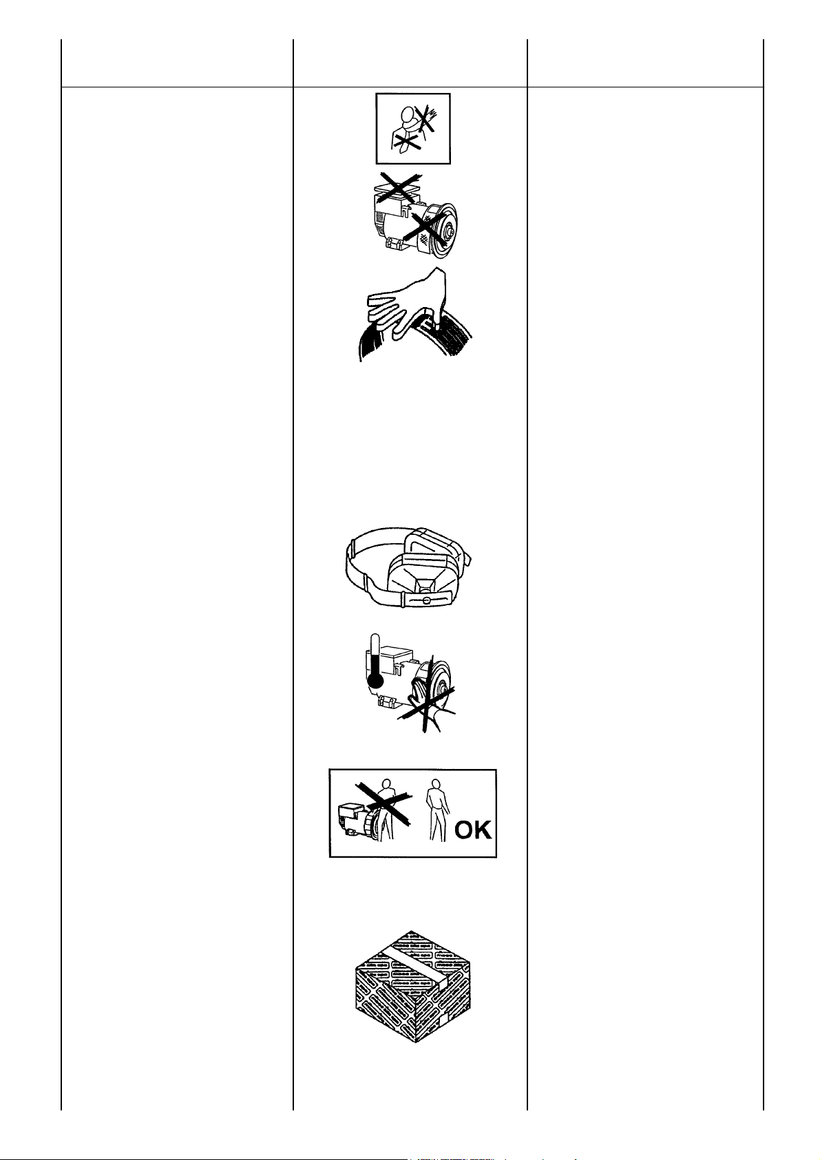
Nelle vicinanze della macchina non ci devono essere persone con indumenti svolazzanti tipo: sciarpe, fular, bracciali, etc e
qualsiasi indumento deve essere chiuso con
elastici alle estremita’.
I generatori non devono mai e per nessuna
ragione funzionare con le seguenti protezioni
aperte:
-) copertura morsetti.
-) coperchi frontali.
-) protezioni delle ventole.
Nelle fasi di montaggio e smontaggio della
rete, assicurarsi di tenere in posizione con le
mani la stessa per evitare che l’elasticità della
rete possa colpire l’operatore o chi è nelle
vicinanze.
In alcuni tipi di generatore i regolatori sono
corredati di 3 led visibili dall’esterno (standard
per macchine grandi e opzionale per
macchine piccole):
Verde
- funzionamento regolare
Giallo
- intervento protezione sovraccarico
Rosso - intervento protezione bassa
velocita’.
I generatori sono rumorosi (tav. 25 pag. 73);
anche se il livello acustico è sicuramente
inferiore a quello del motore primario, devono
essere installati in ambienti isolati (stanza,
sala macchine, etc.) e chi vi accede deve
munirsi di cuffie antirumore.
I generatori sviluppano calore anche elevato
in funzione della potenza generata.
Pertanto non toccare il generatore se non
con guanti antiscottatura e attendere, una
volta spento, che esso raggiunga la
temperatura ambiente.
Anche se la macchina e’ protetta in tutte le
sue parti evitare di sostare nelle sue vicinanze.
Per nessuna ragione appoggiarsi o sedersi
sul generatore.
Non togliere per nessuna ragione le etichette,
anzi richiederne la sostituzione in caso di
necessita’.
PERICOLO DI CORTO CIRCUITO
Il generatore e’ costruito con grado di protezione IP21; pertanto e’ fatto divieto di
utilizzare qualsiasi tipo di idropulitrice e di
spruzzare liquidi sopra le parti elettriche.
In caso di sostituzione di pezzi di ricambio
richiedere esclusivamente ricambi originali.
Per la sostituzione di parti usurate comportarsi rigorosamente come descritto al capitolo
manutenzione; queste manutenzioni devono
essere eseguite da tecnici adeguatamente
qualificati.
No person must wear fluttering clothes (such
as scarves, etc.) near the machine and any
garment must be fastened with elastic bands
at its ends.
The generators must never and for no
reason run whith following guards removed:
-) terminals cover
-) front covers
-) fan guards.
During assembling and disassembling
operations, hold carefully both ends of the
protection grid as the related material
elasticity can be harmful.
In some machines the regulators are
equipped with 3 leds which can be seen from
the outside (as standard equipment on large
machines, as optional equipment on small
machines):
Green led - correct operation
Yellow led - overload protection on
Red led - low speed protection on.
The generators are noisy (table 25 pag. 73);
even if the sound level is certainly lower than
that of the prime motor, they must be
installed in soundproof rooms (room, engine
room, etc.) where it is necessary to wear
antinoise protectors.
The generators produce heat proportional to
the output.
Therefore, do not touch the generator if you
do not wear antiscorch gloves and, after
switching it off, do not touch it until it has
cooled down.
Even if all the machine components are
protected, keep away from the machine.
Do not lean or sit on the generator for
whatever reason.
Do not remove the labels for whatever
reason; on the contrary, if necessary, replace
them.
DANGER OF SHORT CIRCUIT
the degree of protection of the generator is
IP21; therefore it is made prohibition to use
whichever type of hydrocleaner and to spray
liquids over the parts containings electrical
components.
In case of replacement of spare parts, use
original spare parts only.
For the replacement of worn parts, carefully
follow the maintenance instructions; these
operations must be carried out by skilled
technicians.
12
ECO-ECP MANUAL September 2012 revision 32
Page 13

PRESCRIPTIONS
DE SECURITE
SICHERHEITS
VORSCHRIFTEN
PRECAUCIONES
DE SEGURIDAD
Dans le voisinage de la machine, il ne doit y
avoir aucune personne portant des
v ê t e m e n t s flottants type écharpe,
foulard... et quelque soit le vêtement, il doit
être fermé avec un élastique à l'extrémité.
Les alternateurs ne doivent jamais et pour
aucune raison fonctionner avec les
protections suivantes ouvertes:
-) couvercle de boite à bornes
-) fermeture frontale
-) protection du ventilateur.
Durant l' assemblage ou le démontage de la
grille de protection, s' assurer de bien
maintenir la grille avec les mains pour éviter
que l'élasticité de cette pièce ne puisse
blesser l'utilisateur ou les personnes
avoisinantes.
Pour chaque installation (standard sur les
grosses machines et en option sur les petites
machines) les régulateurs sont
accompagnés de 3 led visibles de l'éxterieur:
Vert - Fonctionnement normal et correct
Jaune - intervention de protection de
surcharge
Rouge - intervention de protection de
sous vitesse.
La machine génère du bruit (tab. 25 pag. 73)
même si son niveau est inférieur à celui du
moteur, il doit être alors installé dans un local
isolé et il est nécessaire pour les personnes
d'être munies de casque antibruit.
Les alternateurs produisent de l'énergie
calorifique directement proportionnelle à la
puissance utilisée.
Par conséquent ne pas toucher l'alternateur
ou bien avec des gants appropriés, et
attendre que celui-ci une fois arrêté soit de
nouveau à la température ambiante.
La machine est protégée dans tout son
environnement, éviter de rester dans son
voisinage.
Pour aucune raison, il ne faut s'appuyer ou
s'asseoir sur l'alternateur.
Ne pas arracher non plus les étiquettes ou
adhésifs, au contraire, les réclamer en cas de
nécessité.
DANGER DE COURT CIRCUIT
Le générateur répond à une protection IP21;
par conséquent il est interdit d’utiliser
n'importe quel type d’hydroébarbeuse et de
pulvériser des liquides au-dessus des parties
contenant des pièces électriques.
En cas de changement de tout composant, il
est indispensable de les remplacer par les
pièces d'origine .
Ces modifications doivent être exécutées par
du personnel technique qualifié.
In der Nähe der Maschinen dürfen sich keine
Personen aufhalten, die nicht eng anliegende Kleidungs-oder Schmuckstücke tragen
(wie z.B.Schals,Tücher, Armbänder, usw.).
Jedes Kleidungsstück muß an den Gelenken
durch Gummis geschlossen werden.
Die Generatoren dürfen niemals und aus
keinem Grund in Betrieb sein, wenn folgende
Schutzvorrichten geöffnet sind:
-) Klemmenabdeckung
-) Frontdeckel, Abdeckungen,
-) Schutzvorrichtungen des Lüfterrades.
Bei der Montage und Demontage des
Schutzgitters muss sichergestellt werden,
dass dieses mit beiden Händen festgehalten
wird. Damit soll vermieden werden, dass das
G itter aufgrund seiner elastischen Spannung
den Bediener oder in der Nähe befindliche
Personen verletzt.
Bei einigen Installationen (Standard für große
Maschinen und Optional für kleine
Maschinen) sind die Regler mit drei von
außen sichtbaren LED's ausgestattet.
grün -Normalbetrieb
gelb -Sicherheitseingriff
Überlastung
rot -Sicherheitseingriff geringe
Drehzahl.
Die Generatoren sind laut (Abb. 25 Seite 73);
auch wenn der Geräuschpegel durchaus
unterhalb dem Pegel des Hauptmotors liegt,
müssen sie in isolierten Räumlichkeiten
(Räume, Maschinenräume, usw.) aufgestellt
werden. Personen, die diese Räume
betreten, müssen sich mit Kopfhöhrern vor
dem Lärm schützen.
Die Generatoren entwickeln Wärme auch in
erhöhtem Maße, jeweils in Abhängigkeit von
der erzeugten Leistung. Aus diesem Grunde
ist die Maschine nur mit Verbrennungsschutzhandschuhen zu berühren.
Ist die Maschine ausgeschaltet, ist
abzuwarten, daß diese wieder Umgebungstemperatur annimmt.
Auch wenn die Maschine vollständig
abgesichert ist, ist der Aufenthalt in ihrer
Nähe zu vermeiden.
Aus keinem Grunde darf man sich an den
Generator lehnen oder sich auf ihn setzen.
Aus keinem Grunde sind die Etiketten zu
entfernen, stattdessen ist bei Bedarf Ersatz
anzufordern.
GEFAHR VON KURZSCHLÜSSEN
Der Generator wird in der Schutzart IP21
konstruiert; folglich ist es verboten die
elektrischen Teile zu bespritzen und Behälter
mit Flüssigkeiten auf diese zu stellen.
Müssen Teile ausgewechselt werden, sind
ausschließlich originale Ersatzteile anzufordern.
Beim Austausch von Verschleißteilen
müssen die im Kapitel "Wartung"
angegebenen Vorschriften strengstens
eingehalten werden; diese Wartungsarbeiten
müssen von entsprechend qualifizierten
Technikern durchgeführt werden.
13
En próximidades de la máquina no deberá
haber personas con indumentaria volante
como pulseras, bufandas, etc. Qualquier otro
tipo de indumentaria deberá ser fijada con
elásticos en las extremidades.
Los generadores no deberán bajo ninguna
condición funcionar con las siguientes
protecciones descubiertas:
-) tapa de bornes
-) tapas frontales
-) protección de ventilador.
En las fases de montaje y desmontaje de la
red asegurarse de mantenerla en posicion
con las manos al fin de evitar que la
elasticidad de la red pueda golpear el
operador o alguien cercano a el.
En algunas instalaciones (standard en
máquinas grandes, y opcional en máquinas
pequeñas) los reguladores electrónicos
poseen 3 leds visibles externamente.
Verde -Funcionamiento correcto
Amarillo -Actuación de la protección
de sobrecarga
Rojo -Actuación de la protección
de baja velocidad.
Los generadores son ruidosos (tab. 25 pag.
73), y si bien su nivel acústico es
seguramente inferior al motor primario, los
mismos deberán ser instalados en
ambientes aislados (cabina, sala máquimas,
etc.) y las personas que acceden deberán
llevar auriculares antiruido.
Los generadores producen calor, y el mismo
puede ser elevado en función de la potencia
generada,por lo tanto no tocar la máquina si
no se posee quantes antiquemaduras,
después de un tiempo de haber detenido el
generador, hasta que el mismo alcance la
temperatura ambiente.
Si bien la máquina está protegida en todas
sus partes, evitar de pararse cerca de la
misma.
Por ninguna razón apoyarse o sentarse
sobre el generador.
No quitar por ninguna razón las etiquetas,
por el contrario, pedir la sustitución en caso
de necesidad.
PELIGRO DE CORTOCIRCUITO
El generador es construido con el grado de
protección IP21; por lo tanto se hace
prohibición para utilizar cualquier tipo de
hydrocleaner y rociar líquidos concluído
sobre las piezas eléctricos.
En caso de sustitución de partes de
repuesto, exigir exclusivamente repuestos
originales.
Para la sustitución de partes usadas,
comportarse rigurosamente como descripto
en el capítulo mantenimiento; estas
operaciones deberán ser realizadas por
técnicos adecua-damente calificados.
ECO-ECP MANUAL September 2012 revision 32
Page 14
TRASPORTO E
IMMAGAZZINAMENTO
TRANSPORT
AND STORAGE
PERICOLO
DANGER
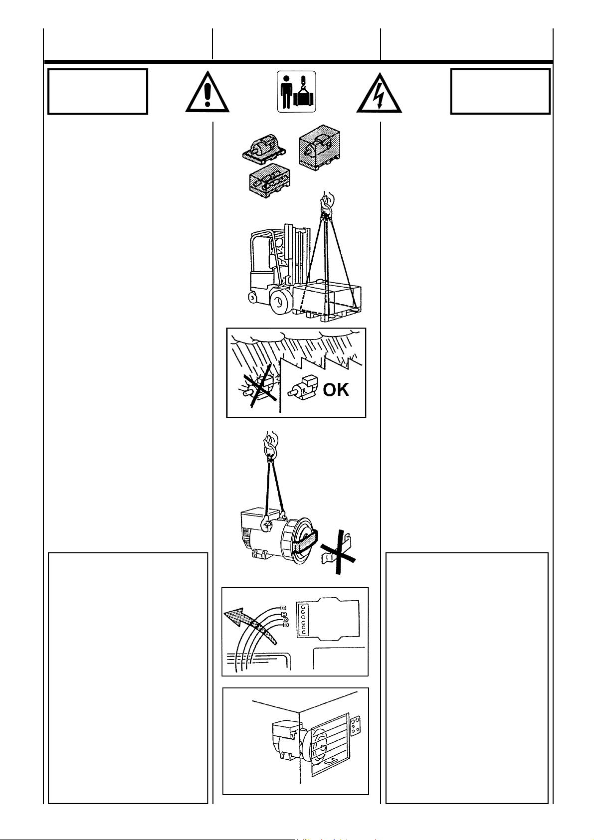
In funzione della destinazione, gli alternatori
possono essere imballati per la spedizione in
vari modi.
In ogni caso per movimentarli, osservare
nella bolla di accompagnamento, il peso, e
con mezzi adeguati, sollevarli da terra il
meno possibile.
Nel caso che l’imballo debba essere
movimentato con carrelli, occorre che le
forche siano tenute piu’ larghe possibile, in
modo da evitare cadute o scivolamenti.
In caso di immagazzinamento, gli alternatori
imballati e non, devono essere depositati in
un locale fresco e asciutto e comunque mai
esposto alle intemperie.
Una volta disimballato il generatore, (monosupporto) non scollegare il sistema di
fissaggio rotore, in quanto quest’ultimo
potrebbe scivolare.
Per la movimentazione al fine dell’installazione, sollevare i generatori, sempre,
attraverso i propri golfari (tav. 25 pag. 73).
GEFAHR
PELIGRO
Alternators will be packed for shipment in a
manner suitable to their mode of transport
and final destination.
Prior to handling goods, please ensure that
lifting equipment is of sufficient capacity.
Under lifting conditions machinery should be
elevated to a minimal distance from the
ground.
When lifting or moving goods by forklift
apparatus, care should be taken to ensure
that forks are correctly positioned to prevent
slipping or falling of pallet or crate.
Both packed and unpacked alternators shall
be stored in a cool and dry room, and shall
never be exposed to the inclemency of the
weather.
With regard to single bearing alternators
(form MD35) please ensure that the rotor
securing device is in place. Failure to do so
may lead to slippage or assembly.
When installing the alternators, always lift
them by using their eyebolts (table 25 pag
73).
IMPORTANTE:
DOPO LUNGHI PERIODI DI IMMAGAZZINAMENTO O IN PRESENZA
DI SEGNI EVIDENTI DI UMIDITA’ /
CONDENSA, VERIFICARE LO
STATO D’ISOLAMENTO.
LA PROVA DI ISOLAMENTO DEVE
ESSERE ESEGUITA DA UN
TECNICO ADEGUATAMENTE QUALIFICATO.
PRIMA DI ESEGUIRE TALE PROVA
E’ NECESSARIO SCONNETTERE
IL REGOLATORE DI TENSIONE;
SE LE PROVE DARANNO UN
RISULTATO TROPPO BASSO
(INFERIORE A 1 MΩ)(EN60204-1)
SI DOVRA’ ASCIUGARE
L’ALTERNATORE IN UN FORNO A
50 - 60C°.
14
IMPORTANT :
AFTER PROLONGER STORAGE OR
IF THE MACHINES SHOW SIGNS OF
CONDENSATION, ALL WINDINGS
SHOULD BE SUBJECTED TO
INSULATION TESTS PRIOR TO
OPERATING.
THE INSULATION TEST SHALL BE
MADE BY SKILLED PERSONNEL.
BEFORE CARRYING OUT THE
TEST, THE VOLTAGE REGULATOR
MUST BE DISCONNECTED; IF THE
TEST RESULTS ARE TOO LOW
(LOWER THAN 1 MΩ)(EN60204-1)
THE ALTERNATOR MUST BE
DRIED IN AN OVEN AT 50-60°C.
ECO-ECP MANUAL September 2012 revision 32
Page 15
TRANSPORT
ET STOCKAGE
TRANSPORT
UND LAGERUNG
TRANSPORTE
Y DEPOSITO
PERICOLO
DANGER
Les alternateurs seront emballés pour
expédition en fonction du mode de transport
et de leur destination.
En cas de déplacement des caisses, il est
nécessaire de contrôler sur le bordereau de
livraison le poids et, avec du materiél
adéquate les soulever de terre le moins haut
possible.
Dans le cas ou l’emballage devra être
déplacé avec des chariots élévateurs, il est
nécessaire que les sangles soient tenues le
plus large possible de façon à éviter des
chutes ou des glissements.
En cas de stockage, les alternateurs emballés ou non, doivent être déposés dans un
local frais et aéré et jamais exposés aux
intempéries.
Une fois l’alternateur sortie de l’emballage,
(monopalier) ne pas enlever le système de
fixation du rotor, car dans ce cas, ce dernier
pourrait glisser.
Pour les manutentions à la fin de l’installation,
soulever les alternateurs, toujours avec leurs
propres anneaux de levage (tab. 25 pag 73).
IMPORTANT :
APRÈS DE LONGUES PÉRIODES
DE STOCKAGE OU EN PRÉSENCE
DE SIGNES ÉVIDENTS
D’HUMIDITÉ / CONDENSATION,
VÉRIFIER L’ÉTAT D’ISOLEMENT.
L’ESSAI D’ISOLEMENT DOIT ÊTRE
ÉXECUTÉ PAR UN TECHNICIEN
QUALIFIÉ.
AVANT DE PROCÉDER À UN TEL
ESSAI, IL EST NÉCESSAIRE DE
DÉCONNECTER LE RÉGULATEUR
DE TENSION; SI LES VALEURS
MESURÉES SONT INFÈRIEURES À
CELLES REQUISES (INFÈRIEUR À
1 MΩ)(EN60204-1) IL EST
NÉCESSAIRE DE SUPPRIMER
L’HUMIDITÉ EN METTANT
L’ALTERNATEUR DANS UN FOUR
À 50-60°C.
In Abhängigkeit von dem Zielort, können die
Generatoren entsprechend auf verschiedene
Art und Weise für den Versand verpackt
werden.
In jedem Fall sind für den Transport die
Angaben des begleitenden Lieferscheins
bezüglich Gewicht zu beachten; der
Generator soll mit geeigneter Hilfsmittel so
wenig wie möglich vom Boden hochgehoben
werden.
Sollte die Verpackung mit dem Generator mit
Gabelstaplern bewegt werden müssen, ist es
erforderilch, die Gabelstellung so weit wie
möglich einzustellen, um dadurch zu
verhindern, daß die Verpackung herunterfallen oder herunterrutschen kann.
Die Lagerung von verpackten und
unverpackten Generatoren muß in einem
kühlen und trockenen Raum erfolgen, der
keinesfalls Wittarungseinflüssen ausgesetzt
ist.
Sobald der Generator (1 Lager Schild) aus
seiner Verpackung entnommen ist, darf die
Sicherungsvorrichtung für den Rotor nicht
entferntwerden, da dieser abrutschen könnte.
Zum Trasport der Generatoren für
Installationszwecke, dürfen diese stets
ausschließlich an ihren dafür vorgesehenen
Ringschrauben aufgehängt werden (ab. 25
Seite 73).
WICHTIG :
NACH EINER LÄNGEREN LAGERUNGSZEIT ODER BEI DEUTLICHEN ANZEICHEN VON FEUCHTIGKEIT ODER KONDENSAT, IST DER
ZUSTAND DER ISOLIERUNGEN ZU
ÜBERPRÜFEN.
DIE ÜBERPRÜFUNG DER ISOLIERUNG DARF NUR VON EINEM
FACHMANN DURCHGEFÜHRT WERDEN.
VOR DER DURCHFÜHRUNG EINER
SOLCHEN PRÜFUNG IST ES
ERFORDERLICH, DEN
SPANNUNGSSREGLER
ABZUTRENNEN; SOLLTE DIE
ÜBERPRÜFUNG EIN ZU NIEDRIGES
ERGEBNIS ERBRINGEN, (UNTERHALB VON 1 MΩ) (EN60204-1), MUß
DER GENERATOR IN EINEM OFEN
BEI 50-60°C GETROCKNET
WERDEN.
15
GEFAHR
PELIGRO
En función del destino final, los alternadores
podrán ser embalados para su expedición
en varios modos.
En todos los casos, para moverlos, observar
en la factura, el peso y con los medios
adecuados, elevarlos del piso lo menos
posible.
En caso que el embalaje sea movido por
medio de un elevador, será necesario que
las cuerdas del mismo ocupen todo la base
de la caja, para evitar caídas o
deslizamientos.
En caso de depósito, los alternadores con o
sin embalaje, deberán ser puestos en un
lugar fresco y seco o por lo menos nunca ser
expuestos a la intemperie.
Una vez desembalado el generador,
(Monosoporte) no quitar el sistema de
fijación del rotor, pues de otra manera el
mismo podría deslizarse y caer.
Para mover los generadores antes de su
instalación, elevarlos siempre por medio de
sus ganchos respectivos (tab. 25 pag 73).
IMPORTANTE :
DESPUES DE LARGOS PERIODOS
DE DEPOSITO O EN PRESENCIA
DE EVIDENTES SIGNOS DE
HUMEDAD O CONDENSACION,
CONTROLAR EL ESTADO DE
AISLACION.
LA PRUEBA DE AISLACION DEBE
SER EFECTUADA POR UN
TECNICO ADECUADAMENTE CALIFICADO.
ANTES DE REALIZAR LA PRUEBA
ES NECESARIO DESCONECTAR
EL REGULADOR DE TENSION; SI
LOS RESULTADOS SON
DEMASIADO BAJOS (INFERIOR A
1MΩ) (EN60204-1), SE DEBERA
SECAR EL ALTERNADOR EN UN
HORNO A 50-60°C.
ECO-ECP MANUAL September 2012 revision 32
Page 16
TRASPORTO E
IMMAGAZZINAMENTO
TRANSPORT
AND STORAGE
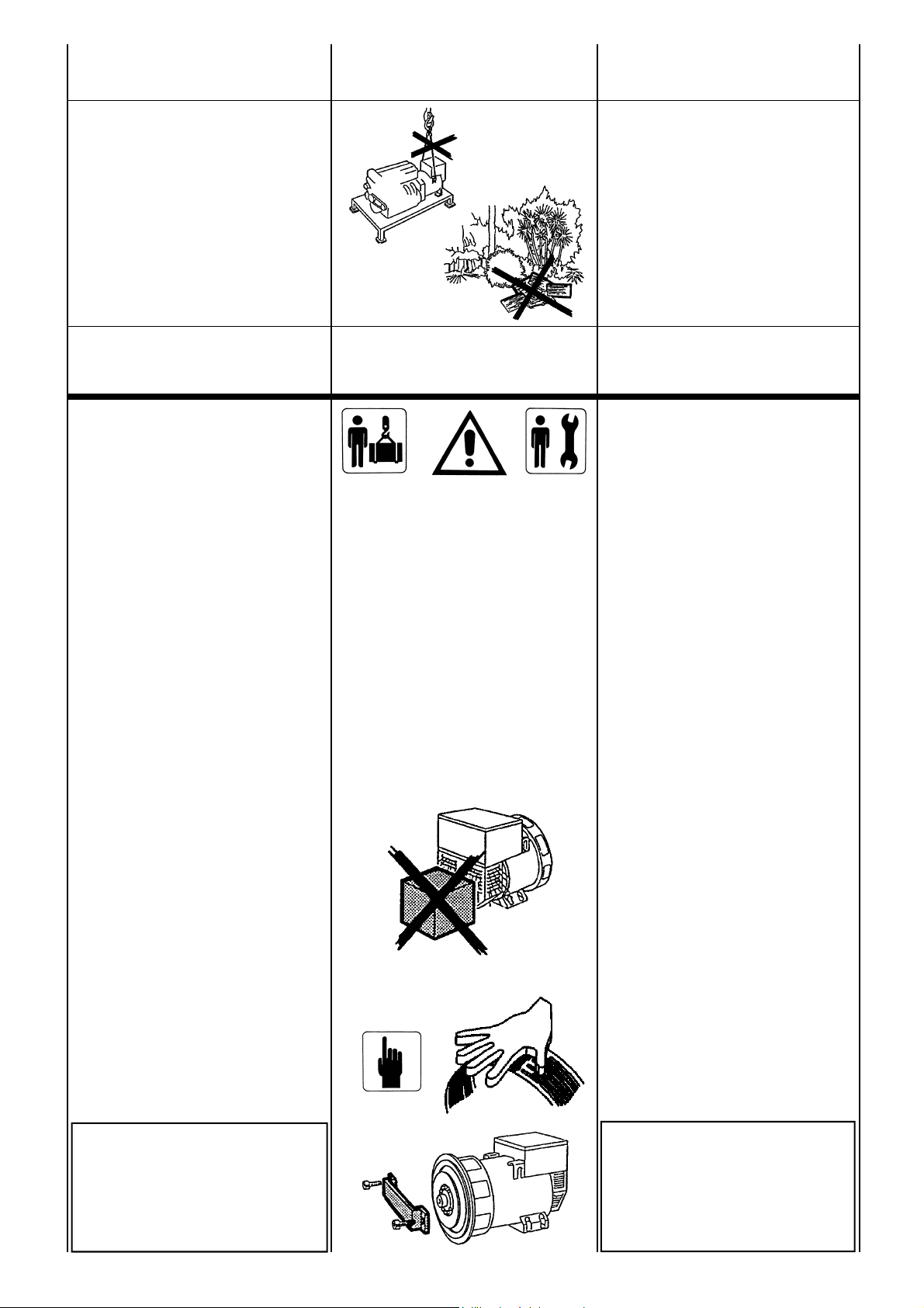
Ricordarsi che, una volta che il generatore
sara’ accoppiato al motore primario, o
montato su un basamento, o installato in un
telaio in modo da formare un corpo unico,
non dovra piu’ essere sollevato dai propri
golfari ma si dovranno seguire le indicazioni
dell’installatore.
Non disperdere l’imballo nell’ambiente, ma
rivolgersi alle agenzie di smaltimento.
ACCOPPIAMENTO
MECCANICO
Con il fine di proteggere, durante il
trasporto e l'immagazzinamento, la
flangia di accoppiamento o la estremita'
d'albero (a seconda della foma
costruttiva del generatore) a tali parti
meccaniche viene applicata una vernice
antiruggine facilmente rimovibile. Tale
sostanza DEVE ESSERE assolutamente
RIMOSSA prima dell'assemblaggio finale.
L’accoppiamento del generatore al motore
primo e’ a cura dell’utilizzatore finale ed e’
eseguito secondo la sua sola discrezione (per
le coppie di serraggio vedere tabella 24 pag.
72) .
Un allineamento impreciso può causare
vibrazioni e danneggiamenti dei cuscinetti. E’
consigliabile inoltre verificare la compatibilità
delle caratteristiche torsionali del motore / generatore (a cura del cliente).
I dati sul generatore necessari per tale verifica
sono disponibili nella relativa documentazione
tecnica.
Le attenzioni richieste sono:
NELLA MESSA IN SERVIZIO AVER CURA
CHE LE APERTURE DI ASPIRAZIONE E
SCARICO DELL’ARIA DI RAFFREDDAMENTO SIANO SEMPRE LIBERE.
IL LATO DI ASPIRAZIONE NON DEVE
ESSERE VICINO A SORGENTI DI
CALORE. IN OGNI CASO, SE NON
SPECIFICATAMENTE CONCORDATO, LA
TEMPERATURA DELL’ARIA DI
RAFFREDDAMENTO DEVE ESSERE
QUELLA AMBIENTE E COMUNQUE NON
SUPERIORE A 40°C.
NELLE FASI DI MONTAGGIO E
SMONTAGGIO DELLA RETE,
ASSICURARSI DI TENERE IN POSIZIONE
CON LE MANI LA STESSA PER EVITARE
CHE L’ELASTICITÀ DELLA RETE POSSA
COLPIRE L’OPERATORE O CHI È NELLE
VICINANZE.
Once the generator is coupled with an
engine, mounted on a baseframe, or installed
on a complete generating set, it cannot be
lifted by its lifting bolts. The relevant
instructions for lifting complete generating set
should be followed.
Any packing materials should be disposed of
via correct waste disposal methods. Do not
discard waste materials into the environment.
MECHANICAL
COUPLING
For transit and storage purposes the
generator flange spigot and the
generator end shaft (for the generators
in B3-B14 construction form) have
been coated with a rust preventer that
can be removed easily.
This MUST BE removed before
assemblying to the engine.
The mechanical coupling is under the sole
responsibility of the final user, and has to be
done at his discretion (for tightening torque
see tab. 24 pag. 72).
A bad alignment may cause vibrations
and bearing damages. It is advisable to
verify the compatibility of the engine /
generator torsional characteristics (by
the customer).
The necessary data for this verification
are available on the concerning
documentation.
Warnings:
BEFORE STARTING THE ALTERNATOR,
CHECK THAT THE AIR INLETS AND
OUTLETS ARE FREE OF ANY
OBSTRUCTIONS.
THE AIR INLETS SHOULD NOT BE NEAR
ANY HEATING SOURCES.
IN ANY CASE, IF NOT SPECIFICALLY
REQUESTED, THE COOLING AIR
TEMPERATURE MUST BE EQUAL TO
THE ENVIRONMENT TEMPERATURE
AND NEVER HIGHER THAN 40°C.
DURING ASSEMBLING AND
DISASSEMBLING OPERATIONS, HOLD
CAREFULLY BOTH ENDS OF THE
PROTECTION GRID AS THE RELATED
MATERIAL ELASTICITY CAN BE
HARMFUL.
IN CASO DI GENERATORI MONOSUPPORTO IN FASE DI ACCOPPIAMENTO CON IL MOTORE PRIMO,
FARE ATTENZIONE CHE IL ROTORE
NON SI SFILI; TOGLIERE IL SISTEMA DI FISSAGGIO ROTORE, SE
PRESENTE.
16
BEFORE MECHANICAL COUPLING
OF SINGLE BEARING
ALTERNATORS REMOVE THE
ROTOR SECURING DEVICE, IF
FITTED, PLACED THERE TO
PREVENT ROTOR FROM SLIPPING.
ECO-ECP MANUAL September 2012 revision 32
Page 17
TRANSPORT
ET STOCKAGE
TRANSPORT
UND LAGERUNG
TRANSPORTE
Y DEPOSITO
Se rappeler qu’une fois l’alternateur accouplé
au moteur d’entraîement, ou monté sur socle,
ou installé sur un châssis de manière à former
un seul bloc, il ne devra plus être soulevé par
ses propres anneaux de levages mais il
faudra suivre les indications de l’installateur.
Ne pais jeter l’emballage dans la nature mais
s’adresser à un centre de recyclage.
ACCOUPLEMENT
MECANIQUE
Dans le but de protéger durant le
transport et le stockage, la flasque
d'accouplement ou l'extrémité de l'arbre
(selon la forme de l'accouplement), il est
appliqué sur ces parties mécaniques un
vernis anti-rouille détachable.
Ce vernis DOIT ETRE absolument
ENLEVE avant l'assemblage final.
L’accouplement de l’alternateur au moteur
d’entraînement est à la charge de l’utilisateur
final et est exécuté selon sa propre méthode
(pour la couple de serrage voir tab. 24 pag.
72).
Un alignement non précis peut engendrer des
vibrations et dommages sur les roulements. Il
est en outre conseillé de vérifier la
compatibilité des caractéristiques torsionnelles
du moteur / alternateur (à charge du client).
Les données nécessaires pour cette
vérification sur l’alternateur sont disponibles
dans la documentation.
Les précautions requises sont :
DANS LA MISE EN SERVICE, S’ASSURER
QUE LES OUVERTURES D’ASPIRATIONS
ET L’EVACUATION DE L’AIR DE
REFROIDISSEMENT SOIENT TOUJOURS
LIBRES.
LE CÔTÉ DE L’ASPIRATION NE DOIT PAS
ÊTRE PRÈS D’UNE SOURCE DE CHALEUR. DANS CHAQUE CAS, S’IL N’Y A
PAS DE SPÉCIFICATION PARTICULIÈRE,
LA TEMPÉRATURE DE L’AIR DE
REFROIDISSEMENT DOIT ÊTRE CELLE
AMBIANTE ET DE TOUTE FAÇON, NE
DOIT PAS ÊTRE SUPÈRIEURE À 40°C.
DURANT L' ASSEMBLAGE OU LE
DÉMONTAGE DE LA GRILLE DE
PROTECTION, S' ASSURER DE BIEN
MAINTENIR LA GRILLE AVEC LES MAINS
POUR ÉVITER QUE L' ÉLASTICITÉ DE
CETTE PIÈCE NE PUISSE BLESSER L'
UTILISATEUR OU LES PERSONNES
AVOISINANTES.
DANS LE CAS DES ALTERNATEURS
MONOPALIER EN PHASE
D’ACCOUPLEMENT AVEC LE
MOTEUR D’ENTRAÎNEMENT, FAIRE
ATTENTION QUE LE ROTOR N’AIT
PAS GLISSÉ SUR SON AXE. OTER LE
SYSTÈME DE FIXATION DU ROTOR.
Sobald der Generator einmal an einen
Antriebsmotor angeschlossen wird, bzw. auf
einem Unterbau montiert oder in einem
Rahmen installiert wird, so daß ein einziger
Block entsteht, darf er nicht mehr an den
Ringschrauben angehoben werden.
Es sind die Vorschriften des AggregateKonstrukteurs zu beachten.
Die Verpackung ist durch die entsprechen
den Entsorgungsunternehmen zu entsorgen.
MECHANISCHER
ANSCHLUß
Zum Transport und zur Lagerung sind
die Anschlussflächen am Gehäuse
und das Ende der Rotorwelle (bei
Zweilagergeneratoren der Bauform B3
-B14) mit einem Rostschutzlack
bestrichen, welcher leicht abziehbar
ist. Dieser MUSS UNBEDINGT vor der
Montage entfernt werden.
Der Anschluß des Generatores an einen
Antriebsmotor obliegt dem Anwender und
erfolgt nach eigenen Ermessen (für das
Anzugsmoment siehe abb. 24 Seite 72).
Eine ungenaue Ausrichtung kann zu
Vibrationen und Beschädigungen der Lager
führen. Es sollte außerdem überprüft
werden, ob die Dreheigenschaften des Motors / Generators kompatibel sind (dafür ist
der Kunde verantwortlich). Die erforderlichen
Angaben für diese Änderung sind in den
entsprechenden Unterlagen verfügbar.
Folgende Punkte sind zu beachten :
BEI DER INBETRIEBNAHME IST ZU
GEWÄHRLEISTEN, DAß DIE ÖFFNUNGEN FÜR DIE ANSAUGUNG BZW. FÜR
DEN AUSTRITT DER KÜHLLUFT IMMER
FREI BLEIBEN.
DIE ANSAUGSEITE DARF SICH NICHT
IN DER NÄHE VON WÄRMEQUELLEN
BEFINDEN. FALLS NICHT
ANDERWEITIG VEREINBART, MUß DIE
KÜHLLUFT RAUMTEMPERATUR
AUFWEISEN UND DARF DEN WERT
VON 40°C NICHT ÜBERSCHREITEN.
BEI DER MONTAGE UND DEMONTAGE
DES SCHUTZGITTERS MUSS
SICHERGESTELLT WERDEN, DASS
DIESES MIT BEIDEN HÄNDEN
FESTGEHALTEN WIRD. DAMIT SOLL
VERMIEDEN WERDEN, DASS DAS G
ITTER AUFGRUND SEINER
ELASTISCHEN SPANNUNG DEN
BEDIENER ODER IN DER NÄHE
BEFINDLICHE PERSONEN VERLETZT.
BEI EIN LAGER SCHILD GENERATOREN IST IN DER PHASE DES
ANSCHLUSSES AN DEN
ANTRIEBSMOTOR DARAUF ZU
ACHTEN, DAß SICH DER ROTOR NICHT
LÖST; EINE EVENTUELL VORHANDENE
BEFESTIGUNGSSICHERUNG DES
ROTORS IST ZU ENTFERNEN.
17
Recordar que, una vez que el generador
será acoplado al motor primario, o montado
en su base, o instalado en una estructura de
manera de formar un cuerpo único, no
deberá ser elevado por medio de sus
ganchos, sino que se deberán seguir las
indicaciones del instalador.
No dejar que el embalaje se pierda en el
ambiente, dirigirse siempre a cualquier
agencia que trate el reciclaje de residuos.
ACOPLAMIENTO
MECANICO
Con el fin de proteger, durante el
transporte, la brida de acople o la
extremidad del eje (segun la forma
constructiva del alternador) a tales
partes mecanicas se aplica un barniz
antioxido que puede quitarse
facilmente. Dicha substancia debe
absolutamente ser quitada antes del
ensamblaje final.
El acoplamiento del generador al motor
primario es responsabilidad del usuario final,
y el mismo será efectuado a propia
discreción (par de torque tab. 24 pag. 72).
Un alineamento incorrecto puede causar
vibraciones o daños a los cojinetes.
Ademas se aconseja verificar la compatibilidad
de las caracteristicas torsionales del motor /
generador (respon-sabilidad del cliente). Los
valores del generador para realizar esta
comprobacion estan disponibles en la respectiva
documentacion.
Los puntos de atención requeridos son :
EN LA PUESTA EN SERVICIO
ASEGURARSE QUE LAS ABERTURAS
DE ASPIRACION Y DESCARGA DEL
AIRE DE REFRIGERACION SE
ENCUENTREN SIEMPRE LIBRES DE
OBSTACULOS.
EL LADO DE ASPIRACION NO DEBE
ESTAR CERCA A FUENTES DE CALOR.
DE CUALQUIER MANERA, SI NO ES
PREVIAMENTE CONVENIDO, LA TEMPERATURA DEL AIRE DE RIFREGERACION DEBE SER AQUELLA DEL
AMBIENTE, DE TODOS MODOS NO
SUPERIOR A 40 °C.
EN LAS FASES DE MONTAJE Y
DESMONTAJE DE LA RED
ASEGURARSE DE MANTENERLA EN
POSICION CON LAS MANOS AL FIN DE
EVITAR QUE LA ELASTICIDAD DE LA
RED PUEDA GOLPEAR EL OPERADOR
O ALGUIEN CERCANO A EL.
EN CASO DE GENERADOR MONOSOPORTE EN FASE DE ACOPLAMIENTO CON EL MOTOR PRIMARIO,
ASEGURARSE QUE EL ROTOR NO
SE DESLIZE; QUITAR EL SISTEMA
DE FIJACION DEL MISMO.
ECO-ECP MANUAL September 2012 revision 32
Page 18
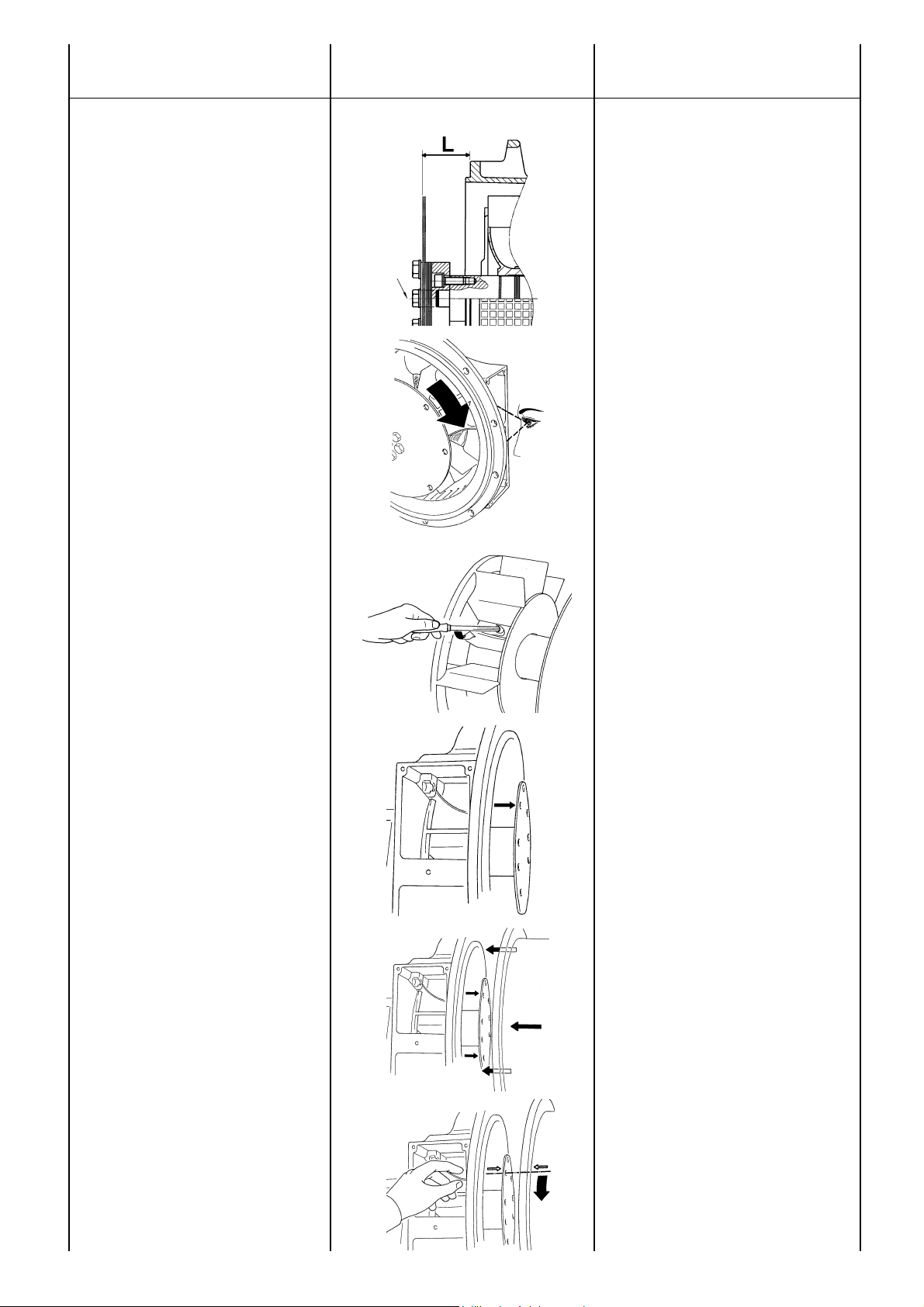
ACCOPPIAMENTO
MECCANICO
MECHANICAL
COUPLING
ISTRUZIONI PER MONTAGGIO IN
FORMA COSTRUTTIVA MD35.
Un allineamento impreciso può causare
vibrazioni e danneggiamenti dei
cuscinetti. E’ consigliabile inoltre
verificare la compatibilità delle
caratteristiche torsionali del motore /
generatore (a cura del cliente).
I dati sul generatore necessari per tale
verifica sono disponibili nella relativa
documentazione tecnica.
Per l’accoppiamento del generatore
con forma costruttiva MD35, procedere
come segue:
a) verificare il corretto posizionamento
dei dischi (quota “L”) in funzione del
tipo di accoppiamento considerato
(tavola 24 pag. 72); se necessario
ripristinare la quota “L” spostando
leggermente e assialmente il rotore. In
posizione corretta il cuscinetto
posteriore deve avere un gioco assiale
da 0,5 a 2 mm.
b) (Per serie 28) attraverso una delle
due aperture laterali e ruotando
manualmente il rotore, individuare sul
mozzo della ventola, la relativa vite di
bloccaggio
c) (Per serie 28) rendere la ventola
libera di ruotare allentando la vite M8 di
bloccaggio, utilizzando una chiave
esagonale possibilmente con testa
snodata
d) (Per serie 28) posizionare uno dei
fori dei dischi in prossimita’ della parte
alta di una delle aperture laterali e
posizionare lo scarico realizzato su una
delle pale della ventola, nella stessa
posizione
e) avvicinare l’alternatore al motore di
accoppiamento
f) allineare uno dei fori di fissaggio dei
dischi del volano con il foro dei dischi
precedentemente posizionato (punto
“d”)
18
INSTRUCTIONS FOR THE ASSEMBLING OF GENERATORS WITH
MD35 FORM.
A bad alignment may cause vibrations
and bearing damages. It is advisable to
verify the compatibility of the engine /
generator torsional characteristics (by
the customer).
The necessary data for this verification
are available on the concerning
documentation.
For the coupling of a generator with
MD35 form, proceed as follows:
a) according to the type of the coupling,
verify the correct placement of the discs
(dimension “L”) (table 24 pag. 72); if
necessary restore the “L” dimension
moving gently and axially the rotor. In
the right position the clearance of rear
bearing should be from 0.5 to 2 mm.
b) (For series 28) through one of the
two lateral openings, and by manually
rotating the rotor, detect the relevant
clamp screw on the fan hub
c) (For series 28) let the fan be free to
rotate by slackening the M8 screw by
means of an hexagonal wrench,
possibly having an articulated head
d) (For series 28) position one of the
disk holes near the upper part of one of
the side openings and place the slit that
is on one of the fan blades, in the same
position
e) move the generator close to the
coupling engine
f) align one of the flywheel disk
fastening holes with the holes of the
previously positioned disks (point “d”)
ECO-ECP MANUAL September 2012 revision 32
Page 19

ACCOUPLEMENT
MECANIQUE
MECHANISCHER
ANSCHLUß
ACOPLAMIENTO
MECANICO
INSTRUCTIONS POUR LE MONTAGE
SOUS LA FORME MD35.
Un alignement non précis peut
engendrer des vibrations et dommages
sur les roulements. Il est en outre
conseillé de vérifier la compatibilité des
caractéristiques torsionnelles du moteur / alternateur (à charge du client).
Les données nécessaires pour cette
vérification sur l’alternateur sont
disponibles dans la documentation.
Pour le couplage du générateur sous
la forme MD35, procéder ainsi:
a) vérifier le positionnement correct des
disques (dimension “L”) en fonction du
type d'accouplement considéré
(tableau 24 pag.72); si besoin remettre
la cote “L” en poussant légèrement et
axialement le rotor. En position
correcte, le roulement arrière doit avoir
un jeu axial de 0.5 à 2 mm.
b) (Pour serie 28) à travers une des
deux ouvertures latérales et en
tournant manuellement le rotor, repérer
la vis de blocage correspondante sur le
moyeu du ventilateur
c) (Pour serie 28) faire en sorte que
l’hélice puisse tourner en dévissant la
vis M8 de blocage en utilisant une clé
hexagonale, si possible avec tête à
joint
d) (Pour serie 28) placer un des trous
des disques à proximité de la partie
haute d’une des ouvertures latérales et
placer le délestage réalisé sur une des
pales du ventilateur, dans la même
position
e) approcher l'alternateur au moteur de
couplage
f) aligner un des trous de fixation des
disques du volant avec le trou des
disques placé précédemment (point
"d")
MONTAGEANWEISUNGEN FÜR IN
BAUFORM MD35.
Eine ungenaue Ausrichtung kann zu
Vibrationen und Beschädigungen der
Lager führen. Es sollte außerdem
überprüft werden, ob die
Dreheigenschaften des Motors /
Generators kompatibel sind (dafür ist
der Kunde verantwortlich). Die
erforderlichen Angaben für diese
Änderung sind in den entsprechenden
Unterlagen verfügbar.
Zur Koppelung des Generators mit Bauform
MD35 ist wie folgt vorzugehen:
a) Überprüfen Sie die ordnungsgemäße
Position der Scheiben (abmessung “L”)
je nach gewünschter Kupplung (Tabelle
24, Seite 72). Falls erforderlich, können
Sie das Maß "L" durch leichtes axiales
Verschieben des Rotors wieder
herstellen. In der korrekten Position
muss das axiale Spiel des hinteren
Lagers zwischen 0,5 und 2,0 mm
liegen.
b) (Für serie 28) Durch eine der zwei
seitlichen Öffnungen und durch
manuelles Drehen des Rotors ist die
entsprechende Blockierschraube auf
der Gebläsenabe zu erkennen
c) (Für serie 28) Das Gebläse zum
freien Drehen bringen, indem man die
Blockierschraube M8 mit einem
entsprechenden sechseckigen,
möglichst gelenkigen Schlüssel lockert
d) (Für serie 28) Eines der zwei
Scheibenlôcher in NÄhe der höheren
Seite einer der seitlichen Öffnungen in
Stellung bringen. Dabei ist der Abfluss,
der sich auf einem der Gebläseflügel
befindet, in gleicher Position zu bringen
e) Den Wechselstromgenerator dem
Koppelungsmotor annähern
f) Eines der zwei Befestigungslöcher
der Schwungradscheiben mit dem
vorher eingestellten Scheibenloch
angleichen (Punkt "d")
INSTRUCCIONES PARA MONTAJE
EN FORMA COSTRUTIVA MD35.
Un alineamento incorrecto puede causar
vibraciones o daños a los cojinetes.
Ademas se aconseja verificar la compatibilidad de las caracteristicas torsionales
del motor / generador (respon-sabilidad
del cliente). Los valores del generador
para realizar esta comprobacion estan
disponibles en la respectiva
documentacion.
Para el acoplaje del generador con
forma costrutiva MD35, proceder como
sigue:
a) verificar el posicionamiento correcto
de los discos (dimensiones “L”) en
funcion del tipo de acople considerado
(tabla 24 pag. 72); si es necesario,
restablecer la cuota "L" reposicionando
leve y axialmente el rotor. En la
posicion correcta el cojinete posterior
debe tener un juego axial de 0.5 a 2
mm.
b) (Para serie 28) a través de una de
las dos aberturas laterales y girando
manualmente el rotor, individualizar en
la placa del ventilador, el
correspondiente tornillo de bloqueo
c) (Para serie 28) liberar el ventilador
soltando el tornillo M8 de bloqueo,
utilizando una llave hexagonal
posiblemente con cabeza desatada
d) (Para serie 28) posicionar uno de los
agujeros de los discos próximos a la parte
alta de una de las aperturas laterales y
posicionar la descarga realizada en una
de las palas del ventilador, en la misma
posición
e) aproximar el alternador del motor de
acoplaje
f) alinear uno de los agujeros de fijación
de los discos del volante con el agujero
de los discos antes posicionado (punto
"d")
19
ECO-ECP MANUAL September 2012 revision 32
Page 20
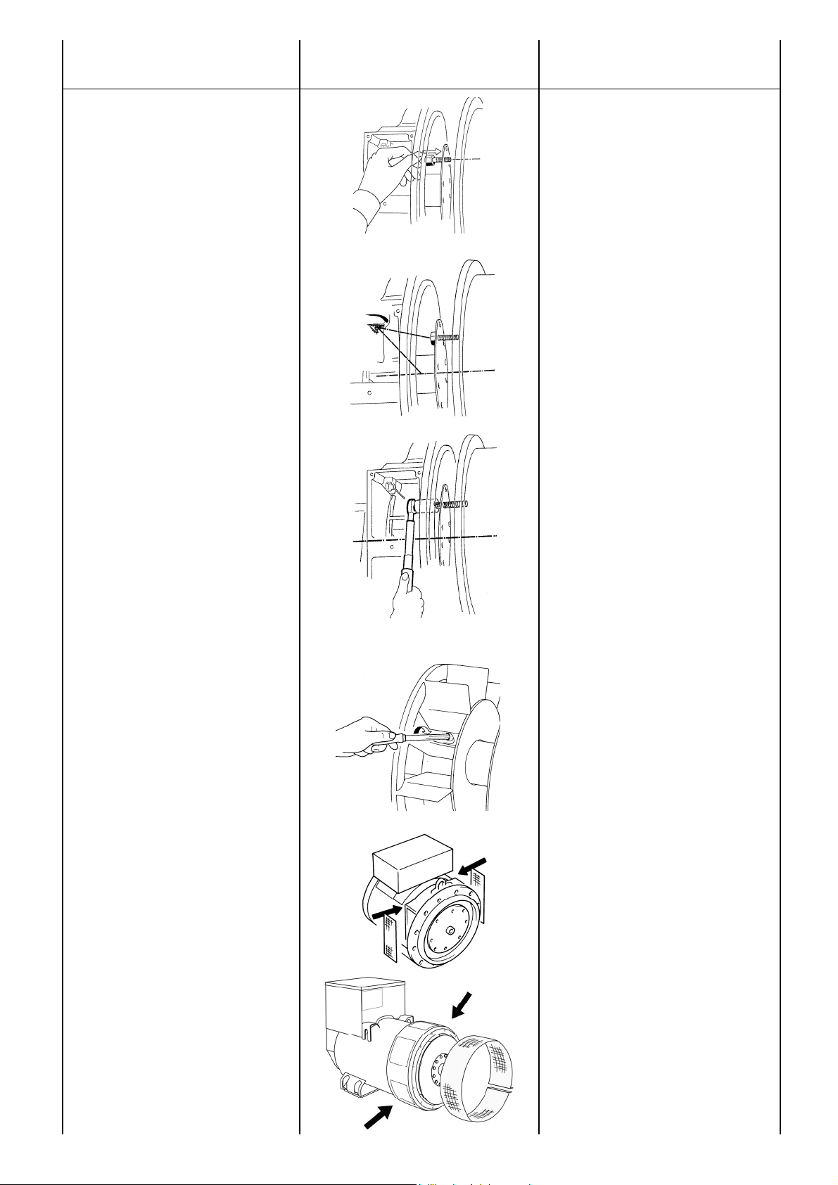
ACCOPPIAMENTO
MECCANICO
MECHANICAL
COUPLING
g) inserire ed avvitare parzialmente la
relativa vite che blocca i dischi al
volano. Tenendo ferma la ventola
(ECP28), ruotare il volano affinchè altri
due fori si ripresentino nella stessa
posizione ed avvitare parzialmente la
relativa vite. Ripetere detta operazione
per tutti gli altri fori
h) dopo aver verificato il corretto
centraggio dei dischi nel volano motore,
bloccare definitivamente dette viti
i) (Per serie 28) terminata l’operazione
di bloccaggio dischi, ribloccare la
ventola serrando la relativa vite con
una coppia di serraggio pari a 16 Nm ±
10%; la posizione radiale della ventola
non è vincolante per il corretto
funzionamento del sistema
l) montare le retine di protezione,
fornite a corredo del generatore.
L’osservanza delle prescrizioni dei
punti “i” ed “l” è di fondamentale
importanza onde evitare seri danni del
generatore e situazioni pericolose per
cose e persone.
Solamente dopo che il generatore e’
stato ben fissato meccanicamente
procedere all’accoppiamento elettrico.
g) Insert and partially tighten the
screws that lock the disks to the
flywheel. Keeping the fan still (ECP28),
turn the flywheel until another two holes
are in the same position and partially
tighten the screw. Repeat this operation
for all the other holes
h) after inspecting the correct centring
of the disks on the engine flywheel, the
screws must be completely tightened
i) (For series 28) once the clamping of
the disks is over, stop the fan once
again by tightening the screw with a
torque wrench setting adjusted at 16
Nm ± 10%; the radial position of the fan
is not binding for the correct operation
of the system
l) fix the protection grids supplied with
the generator.
Compliance with items "i" and "l" is of
the utmost consequence in order to
avoid serious damages to the generator
or hazardous situations for people or
objects.
Only after a correct mechanical coupling, proceed with the electrical
connections.
20
ECO-ECP MANUAL September 2012 revision 32
Page 21

ACCOUPLEMENT
MECANIQUE
MECHANISCHER
ANSCHLUß
ACOPLAMIENTO
MECANICO
g) Insérer et visser partiellement la vis
correspondante qui bloque les disques
au volant. En bloquant le ventilateur
(ECP28), tourner le volant afin que les
autres trous se présentent à nouveau
dans la même position et visser
partiellement la vis correspondante.
Répéter cette opération pour tous les
autres trous
h) après avoir vérifié que le centrage
des disques au volant de moteur est
correct, bloquer définitivement les
susdites vis
i) (Pour serie 28) l'opération de blocage
des disques terminée, bloquer à
nouveau le ventilateur en serrant la vis
correspondante avec un couple de
serrage égal à 16 Nm ± 10%; la
position radiale du ventilateur ne
conditionne pas le bon fonctionnement
du système
l) monter les grilles de protection
fournies avec le générateur.
Le respect des prescriptions des points
"i" et "l" est d’une importance
fondamentale afin d’éviter de sérieux
dommages du générateur et des
situations dangereuses pour les choses
et les personnes.
Seulement après que l’alternateur soit
bien fixé mécaniquement, procéder au
raccordement électrique.
g) Die entsprechende Schraube, die die
Scheiben an dem Schwungrad
blockiert, ist einzuführen und teilweise
festzuschrauben. Bei festgehaltenem
Gebläse ist das Schwungrad zum
rotieren zu bringen (ECP28), bis sich
zwei weitere Löcher in gleicher Stellung
befinden. Hierbei ist die entsprechende
Schraube teilweise festzuschrauben.
Für die restlichen Löcher ist dieser
Vorgang zu wiederholen
h) Nach Feststellung der korrekten
Zentrierung der Scheiben in das MotorSchwungrad, sind die genannten
Schrauben definitiv festzuziehen
i) (Für serie 28) Wenn der Vorgang der
Scheibenblockierung beendet ist, ist
das Gebläse erneut zu blockieren,
indem die entsprechende Schraube mit
einem Drehmoment von 16 Nm ± 10%
zu verriegeln ist; die Radialstellung des
Gebläses ist hierbei für den korrekten
Betrieb des Systems nicht massgebend
l) Montage der Schutznetze, die mit
dem Generator mitgeliefert sind.
Die korrekte Befolgung der unter "i" und
"l" genannten Anweisungen ist von
maßgebender Bedeutung, um
ernsthafte Schäden des Generators zu
verhindern und um Gefahrsituationen
an Sachen und Personen zu
vermeiden.
Erst wenn der Generator mechanisch
richtig befestigt ist, kann mit dem
elektrischen Anschluß fortgefahren
werden.
g) inserir y atornillar parcialmente el
respectivo tornillo que bloquea los discos
al volante. Manteniendo parado el
ventilador (ECP28), dar la vuelta al
volante para que los otros dos agujeros
se pongan otra vez en la misma posición
y atornillar parcialmente el respectivo
tornillo. Repetir la operación para todos
los otros agujeros
h) después de haber verificado el correcto
centraje de los discos en el volante motor,
bloquear definitivamente dichos tornillos
i) (Para serie 28) terminada la operación
de bloqueo de discos, rebloquear el
ventilador cerrando cerrando los tornillos
con un par de torque equivalente a 16 Nm
± 10%; la posición radial del ventilador no
es vinculante para el correcto
funcionamiento del sistema
l) montar las redes de protección,
suministradas junto con el generador.
La observancia de las prescripciones de
los puntos "i" y "l" es de fundamental
importancia para evitar serios daños al
generador y situaciones peligrosas para
cosas y personas.
Solo después que el generador haya sido
convenientemente fijado mecánicamente,
efectuar la conexión eléctrica.
21
ECO-ECP MANUAL September 2012 revision 32
Page 22
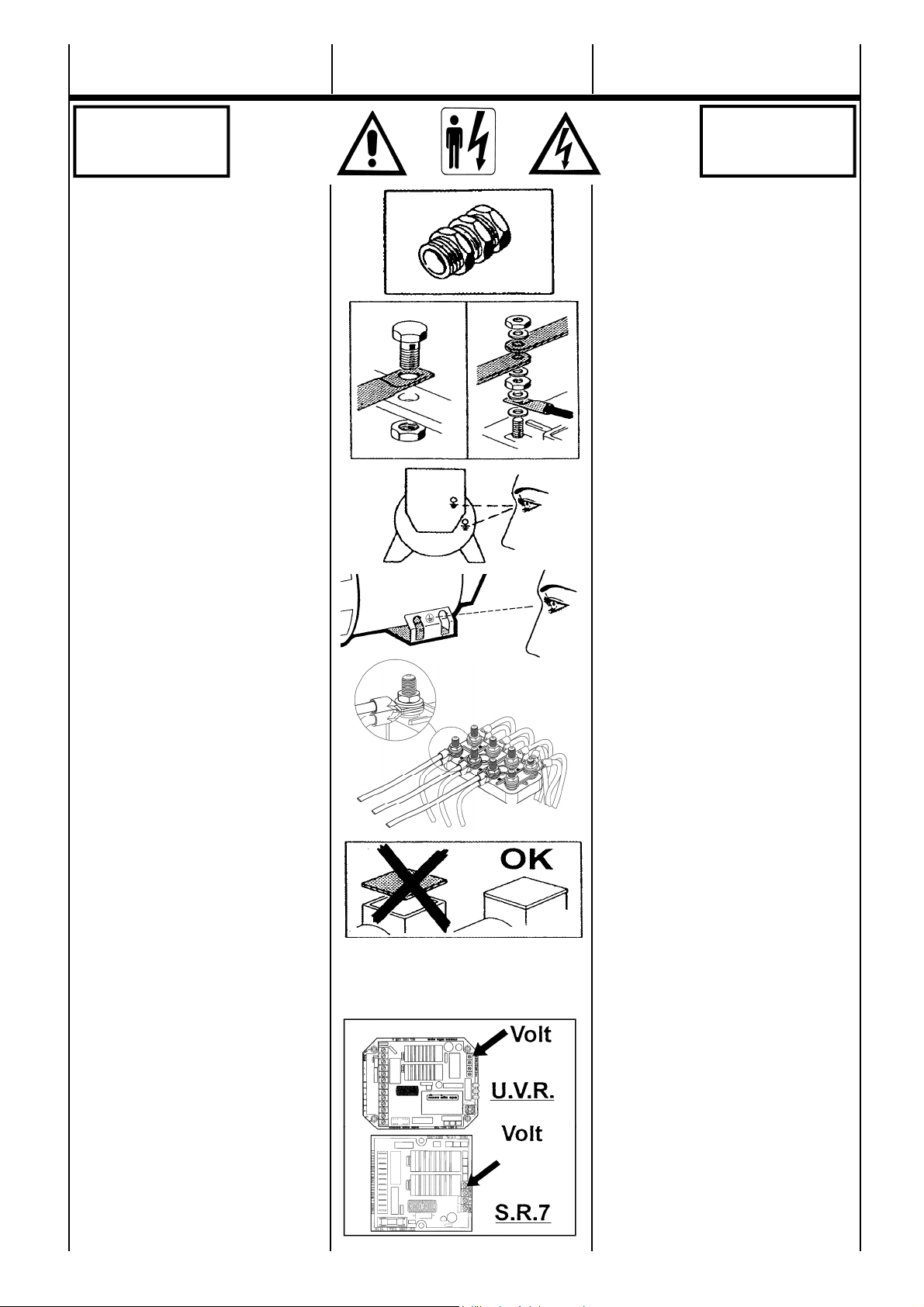
ACCOPPIAMENTO
ELETTRICO
ELECTRICAL
CONNECTIONS
PERICOLO
DANGER
L’accoppiamento elettrico e’ a cura dell’utilizzatore finale ed e’ eseguito secondo la sua
sola discrezione.
Per l’ingresso nella scatola morsetti si raccomanda di utilizzare passacavi e serracavi in
accordo con le specifiche del paese di
esportazione.
COLLEGAMENTO AVVOLGIMENTI
Sono previsti entrambi i collegamenti, stella
con neutro (Y) e triangolo (∆) in tutti gli
alternatori (tav. 2 pag. 60).
Per passare da un collegamento Y a ∆ (es.
da 400V a 230V) e’ sufficiente spostare i
ponti sulla morsettiera principale (vedere
schema tav. 2 pag. 60).
Nessun intervento e’ richiesto sul regolatore
di tensione.
I generatori sono costruiti di serie con 12 cavi
di uscita per consentire di ottenere tensioni
diverse (es.230 / 400 / 460 / 800V).
I generatori, vanno sempre collegati a terra
con un conduttore di adeguata sezione
utilizzando uno dei due (interno/esterno)
appositi morsetti.
Per il collegamento elettrico utilizzare cavi
adeguati in funzione della potenza del generatore ed effettuare le connessioni ai morsetti
come indicato nelle tavole 12 o 17.
Dopo aver eseguito il collegamento (per le
coppie di serraggio vedere tabella 24 pag.72)
rimontare il coperchio scatola morsetti.
IMPORTANTE: variazioni di frequenza.
La macchina fornita per funzionare a 50Hz
puo’ funzionare anche a 60Hz (o viceversa);
e’ sufficiente tarare il potenziometro al nuovo
valore nominale di tensione.
Passando da 50Hz a 60Hz, la potenza puo’
aumentare del 20% (corrente invariata), se la
tensione aumenta del 20%; se la tensione
rimane invariata la potenza, puo’ aumentare
del 5% per effetto della migliore ventilazione.
Per generatori costruiti appositamente per
una frequenza di 60Hz nel passaggio a
50Hz, la tensione e la potenza devono
necessariamente diminuire del 20% rispetto
a quella riferita a 60Hz.
REGOLATORI (tav. 3 pag 60)
I regolatori tipo U.V.R.6/1-F e S.R.7/2-G
possono essere indifferentemente usati nella
serie ECO-ECP senza modificare le
prestazioni.
L’U.V.R.6/1-F e’ montato di serie nelle
tipologie 38 - 40 - 43 - 46, mentre l’S.R.7/2-G
nelle serie 28-31-32-34.
I due regolatori sono perfettamente uguali
nelle prestazioni, ma si differenziano nelle
segnalazioni e nel riferimento.
GEFAHR
PELIGRO
All electrical output connections are the
responsibility of, and are at the discretion of,
the end user.
When making terminal box connections, all
cable and terminal lugs should meet the
relevant standards of the country of final
destination.
WINDINGS CONNECTION
All alternators feature both star with neutral
(Y) and delta (∆) connections (table. 2
pag.60) .
To reconnect from a star to delta connection
(for ex. from 400V to 230V), modify the linking
arrangements on the output terminal board
(see diagram on table 2 page 60).
It is not necessary to adjust the voltage
regulator.
Standard alternators are equipped with 12
cables to offer different voltages (ex.230 /
400 / 460 / 800V).
The alternator must always be earthed by
sufficiently rated cable, using one of the inside
or outside terminals. For the electrical connections use wires suitable for the power of
the generator and connect them to the terminal board as indicated on table 12 or 17.
After completing output connections (for
tightening torque see tab. 24 pag. 72), ensure
that the terminal box cover is securely in
place.
IMPORTANT: frequency variations.
A standard production machine wound for 50
Hz can also function at 60 Hz (and vice
versa) by resetting the A.V.R. voltage
potentiometer to the new nominal voltage
value. When changing from 50 to 60 Hz the
alternator power, and nominal voltage will
increase by 20%, but the current does not
change from 50 Hz value. Should voltage
stay at 50 Hz nominal value, then the output
power may be increased by 5% due to
improved ventilation.
For machines wound for 60 Hz, changing to
50 Hz, the voltage and power values have to
decrease by 20% of 60 Hz value.
REGULATORS (table. 3 pag 60)
Either U.V.R.6/1-F and S.R.7/2-G regulators
can be used on the ECO-ECP series without
affecting performances.
The U.V.R.6/1-F is a standard feature on the
38-40-43-46 models whereas the S.R.7/2-G
is standard on the 28-31-32-34 series.
The two regulators ensure the same level of
performance but have different signal
systems and references.
22
ECO-ECP MANUAL September 2012 revision 32
Page 23
RACCORDEMENT
ELECTRIQUE
ELEKTRISCHER
ANSCHLUSS
CONEXION
ELECTRICA
PERICOLO
DANGER
Le raccordement électrique est à la charge
de l’utilisateur final et il est exécuté par ses
soins.
Pour le raccordement à la boite à bornes, il
est recommandé d’utiliser des passecables et
des serre cables en accord avec les
spécifications du pays d’exportation.
COUPLAGE DES ENROULEMENTS
Tous les alternateurs sont prévus pour être
couplés soit en étoile avec neutre ( Y ) ou soit
en triangle (∆) (tab. 2 pag. 60).
Pour passer de la connexion Y à ∆ (par
exemple de 400V à 230V) il est suffisant de
modifier la position des barettes sur la
planchette à bornes (vois schéma Tab.2 pag.
60).
Aucune intervention n’est nécessaire sur le
régulateur de tension.
Les alternateurs sont construits en série de
12 fils de sortie afin de permettre d’obtenir
plusieurs possibilités de tensions (ex. 230 /
400 / 460 / 800V).
Les alternateurs doivent toujours être reliés à
la terre avec un conducteur de section
adéquate en utilisant une des deux (interne/
externe) bornes appropriées. Pour la connexion électrique, il faut utiliser des sections
de câbles adaptés en fonction de la puissance du générateur et effectuer les connexion
aux bornes selon les tableaux 12 et 17.
Aprés avoir fait la liason (pour la couple de
serrage voir tab. 24 pag. 72), remonter le
couvercle de la boite à bornes.
IMPORTANT: variations de frequence.
L’alternateur est prévu pour un
fonctionnement en 50 Hz et, est également
prévu pour fonctionner à 60 Hz (ou
viceversa). Il est suffisant de tarer le
potentiomètre “Volt” à la nouvelle valeur de
tension. En passant de 50 Hz à 60 Hz, la
puissance augmente de 20% (courant
constant) si la tension augmente de 20%; par
contre si la tension reste identique, la
puissance est augmentée de 5% grace à
l’augmentation de la ventilation.
Pour les alternateurs produits à 60 Hz en
passant à 50 Hz, la tension et la puissance
doivent nécessairement diminuer de 20%.
REGULATEURS (tab. 3 pag 60)
Les régulateurs de type U.V.R.6/1-F et
S.R.7/2-G peuvent être utilisés indifférement
dans la série ECO-ECP sans en modifier les
prestations. L’U.V.R.6/1-F est monté de série
pour les gammes 38-40-43-46, tandis que le
S.R.7/2-G est sur les séries 28-31-32-34.
Les deux régulateurs sont parfaitement
équivalents dans leurs performances, mais
ce sont les signalisations et les informations
qui les différencient.
Der elektrische Anschluß obliegt dem Endanwender und erfolgt nach eigenem
Ermessen. Für den Eingang des
Klemmenkastens wird empfohlen,
Kabelführungen und Kabelschellen zu
verwenden, die den Vorschriften und
Spezifikationen des Exportlandes
entsprechen.
ANSCHLUß WICKLUNGEN
Für alle Generatoren sind beide
Anschlußarten vorgesehen: Stern mit
Stempunktleiter (Y) und Dreieckschaltung (∆) (Abb. 2 Seite 60).
Um von einer Y-Schaltung auf eine ∆-
Schaltung zu wechseln, (z.B. von 400V auf
230V), ist es ausreichend, die Brücken auf
der Hauptklemmleiste zu verschieben (siehe
Schema Abb.2 Seite 60). Für den
Spannungensregler ist keinerlei Eingriff
erforderlich. Bei den Generatoren sind
serienmäßig 12 Wicklungsenden auf das
Hauptklemmbrett herausgeführt, so daß
durch entspre-chendes Umschalten 4
verschiedene Spannungen möglich sind
(z.B. 230/400/460/800V). Die Generatoren
müssen immer mit einem Leiter mit
geeigneten Querschnitt unter Verwendung
einer der dafür vorgesehenen Klemmen
(innen / außen) geerdet werden. Zum Anschluss der Abgangsleitungen am Klemmbrett sind Leitungen mit einem Querschnitt
entsprechend der Generatorleistung zu verwenden. Die Verbindung sollte wie in Abbildung 12 und 17 dargestellt erfilgen.
Nach Durchführung des Anschlusses (für
das Anzugsmoment siehe abb. 24 Seite 72)
ist die Abdeckung des Klemmenkastens
erneut anzubringen.
WICHTIG: Frequenzänderungen.
Ein für 50 Hz vorgesehener Generator kann
durch entsprechende Drehzahländerung
auch mit 60 Hz betrieben werden (oder
umgekehrt). Dazu ist lediglich am
Sollwertpotentiometer die mit der
geänderten Drehhzahl ebenfalls sich
ändernde Spannung wieder auf die
Nennspannung einzustellen. Beim
Übergang von 50 auf 60 Hz darf die
abgenommene Leistung um 20% erhöht
werden. Beim Übergang von 60 auf 50 Hz
müssen umgekehrt sowohl die Leistung als
auch die Spannung wieder entsprechend
reduziert werden.
REGLER (ab. 3 Seite 60)
Die Regler, Typ U.V.R.6/1-F und S.R.7/2-G,
können unterschiedslos in der Serie ECOECP ohne Leistungsänderung verwendet
werden. Der Regler U.V.R.6/1-F ist
serienmäßig in der Typenreihe 38-40-43-46,
eingebaut, während der Regler S.R.7/2-G in
der Typenreihe 28-31-32-34 eingebaut ist.
Die beiden Regler sind in ihrer Leistung
absolut identisch und unterscheiden sich
lediglich durch ihre Meldungen und
Anschlüsse.
GEFAHR
PELIGRO
La conexión eléctrica es responsabilidad del
usuario final y la misma se efectúa a
discreción de este último. Para la entrada en
la caja de bornes se recomienda utilizar pasa
-cables con su sistema de fijación respectivo
en conformidad con las especificaciones del
país de exportación.
CONEXIÓN BOBINADOS
Se preveen ambas conexiones, estrella con
neutro ( Y ) y triángulo (∆) en todos los
alternadores (tab. 2 pag. 60).
Para pasar de una conexión Y a ∆ (ej. de
400V a 230V) es suficiente desplazar los
puentes sobre los bornes principales (ver
esquema tab. 2 pag. 60).
Ningún tipo de intervención es requerido en
el regulador de tensión.
Los generadores son construidos de serie
con 12 cables de salida para permitir
diferentes valores de tensión (ej. 230 / 400 /
460 / 800V).
Los generadores, deben ser siempre
conectados a tierra con un conductor de
sección adequada, utilizando uno de los dos
bornes (interno/externo) previstos para la
misma. Para la conexion electrica utilizar cables adecuados en funcion de la potencia del
alternador y realizar las conexiones a los bornes segun indicado en las tablas 12 o 17.
Después de haber realizado la conexión (par
de torque tab. 24 pag. 72), montar
nuevamente la tapa de la caja de bornes.
IMPORTANTE: variación de frecuencia.
La máquina suministrada para funcionamiento a 50 Hz puede también funcionar a
60 Hz o viceversa. Para ello es suficiente
tarar el potenciómetro al nuevo valor nominal
de la tensión. Pasando de 50 a 60 Hz la
potencia puede aumentar un 20% (corriente
invariable) si la tensión aumenta un 20%. Si
la tensión permanece invariable, la potencia
puede aumentar un 5% por el efecto de una
mejor ventilación. Para generadores
construidos a 60 Hz, al pasar a 50 Hz, la
tensión y la potencia deberán disminuir
necesariamente un 20% con respecto a los
valores de 60 Hz.
REGULADORES (tab. 3 pag 60)
Los reguladores del tipo U.V.R.6/1-F y
S.R.7/2-G pueden ser indiferentemente
utilizados en las series ECO-ECP sin
modificar las características.
El regulador U.V.R.6/1-F es montado de
serie en los tipos 38-40-43-46, mientras que
el regulador S.R.7/2-G en los tipos 28-31-32-
34. Los dos reguladores son perfectamente
iguales en sus características, pero se
diferencian en las señalizaciones y en la
referencia de tensión.
23
ECO-ECP MANUAL September 2012 revision 32
Page 24
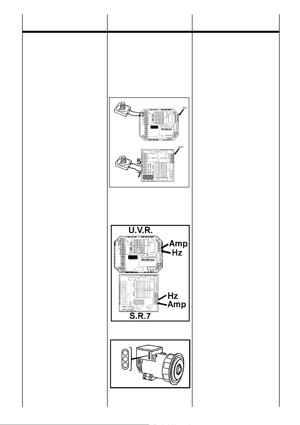
ACCOPPIAMENTO
ELETTRICO
ELECTRICAL
CONNECTIONS
IMPORTANTE :
il controllo di tensione va eseguito a vuoto
con l’alternatore funzionante a frequenza
nominale.
Agendo sul potenziometro tensione dei regolatori elettronici si puo’ ottenere la regolazione della tensione entro il ± 5% del valore
nominale.
E' possibile ottenere la regolazione della
tensione a distanza in un range di ± 5%
inserendo negli appositi morsetti un
potenziometro da 100K (per le macchine a 6
morsetti) o un potenziometro da 100K con in
serie una resistenza da 100K (per le
macchine a 12 morsetti).
Istruzioni per il collegamento del
potenziometro esterno :
ATTENZIONE: quando si collega il
potenziometro esterno è necessario
seguire la procedura sottoriportata per
ottenere un corretto funzionamento
dell'alternatore.
1) Ruotare il trimmer VOLT nel regolatore
elettronico completamente in senso antiorario
2) Posizionare il potenziometro esterno a
meta' corsa e connetterlo agli appositi
morsetti del regolatore elettronico
3) Tramite il trimmer VOLT del regolatore
elettronico tarare la tensione al valore
nominale.
PROTEZIONI
U.V.R.6/1-F - S.R.7/2-G
Entrambi i regolatori sono provvisti di una
protezione di bassa velocita’ la cui soglia di
intervento e’ regolabile tramite il
potenziometro “Hz”. L’intervento di tale
protezione e’ istantaneo riducendo la
tensione di macchina quando la frequenza
scende sotto il 10% di quella nominale. I
regolatori prevedono anche una seconda
protezione (protezione di sovraccarico), che
sente la tensione parzializzata che va al
campo di statore dell’eccitatrice e se essa
supera per piu’ di 20 sec il valore stabilito,
abbassa la tensione di macchina limitando la
corrente di eccitazione entro valori di
sicurezza.
Il ritardo appositamente inserito consente lo
spunto del motore che normalmente si avvia
in 5 - 10 sec. Anche la soglia di intervento di
questa protezione e’ regolabile tramite il
potenziometro “AMP”.
U.V.R.6/1-F
Il regolatore U.V.R.6/1-F aggiunge alle
prestazioni prima descritte, le seguenti
caratteristiche:
1 - possibilita’ di avere il riferimento trifase
oltre che monofase.
2 - segnalazioni a led di autodiagnostica che
indicano le condizioni di funzionamento della
macchina: un led verde, che normalmente
acceso indica il funzionamento normale del
generatore; un led rosso che indica
l’intervento della protezione di bassa velocita’,
un led giallo che indica l’intervento della
protezione di sovraccarico.
24
IMPORTANT :
the generator output voltage must be
checked under no-load conditions, with the
correct setting of frequency.
The voltage may be adjusted by ± 5% of the
nominal, by acting upon the voltage
potenziometer on the electronic regulators.
It is possible to get a remote voltage
regulation of ± 5% inserting in the proper
terminals a 100K potentiometer (for the 6 lead
units) or a 100K potentiometer with a 100K
resistance in series (for the 12 lead units).
Instructions to follow for the external
potentiometer connection:
CAUTION: in order to get a correct working
of the alternator, it is necessary to follow the
following procedure, connecting the external
potentiometer.
1) Turn the VOLT trimmer of the electronic
regulator completely anticlockwise.
2) Set the external potentiometer at half turn
and connect it to the proper terminals of the
electronic regulator.
3) Adjust the voltage at the nominal value by
the VOLT trimmer of the electronic regulator.
PROTECTIONS
U.V.R.6/1-F - S.R.7/2-G
Both regulators are provided with an
underspeed protection with an intervention
threshold which can be adjusted by the
potentiometer marked “Hz”. This protection
intervenes instantaneously by reducing the
alternator voltage to a safe value when
frequency falls below 10% of the nominal
value. These regulators also have inherent
overload protection which senses the exciter
field voltage value. Should this field voltage
value exceed the nominal value for a period
of more than 20 seconds, then again the
alternator voltage is automatically reduced to
a safe operating level. This overload function
has a built-in delay to allow for the overload
when starting motors (normally 5-10
seconds). The operating threshold of this
protection device is adjustable by the
potentiometer marked “AMP”.
U.V.R.6/1-F
Aside from the above mentioned characteristics, the U.V.R.6/1-F regulator also
offers the following:
1 - possibility to have single-phase as well as
three-phase sensing
2 - led indicators for self-diagnosis which
indicate the unit’s operational conditions: a
green led which when lit confirms the
alternator’s normal functioning; a red led
indicates the underspeed protection is on; a
yellow led indicates the overload protection is
on.
ECO-ECP MANUAL September 2012 revision 32
Page 25

RACCORDEMENT
ELECTRIQUE
ELEKTRISCHER
ANSCHLUSS
CONEXION
ELECTRICA
IMPORTANT :
le contrôle de la tension se fait à vide avec
l’alternateur fonctionnant à la fréquence
nominale.
En agissant sur le potentiomètre de tension
du régulateur électronique, on peut obtenir la
régulation de la tension entre ± 5% de la
valeur nominale.
Il est possible d'obtenir la régulation de la
tension à distance dans une plage de ± 5%
en positionnant dans les bornes appropriées
un potentiomètre de 100 K (pour les
machines à 6 bornes) ou un potentiomètre de
100 K avec en série une résistance de 100 K
(pour les machines 12 bornes).
Instructions pour le branchement du
potentiometre exterieur:
ATTENTION : Lorsqu'on connecte le
potentiomètre extérieur, il est nécessaire de
suivre la procédure ci-après décrite pour
obtenir un fonctionnement correct de
l'alternateur.
1) Tourner le potentiomètre "VOLT" dans le
régulateur électronique complètement dans
le sens anti-horaire.
2) Positionner le potentiomètre extérieur à michemin et le brancher aux bornes
appropriées du régulateur électronique.
3) À l'aide du potentiomètre VOLT du
régulateur électronique, régler la tension à la
valeur nominale.
PROTECTION
U.V.R.6/1-F - S.R.7/2-G
Les régulateurs sont pourvus d’une protection
en sous-vitesse dont le seuil est réglabe à
travers le potentiomètre “Hz”.
L’intervention de cette protection est
instantanée en réduisant la tension de la
machine et ce lorsque la fréquence descend
de 10% au dessous de celle préréglée. Les
régulateurs sont également pourvus d’une
seconde protection (protection de surcharge)
qui enregistre une partie de la tension
d’alimentation du stator d’excitatrice. Si cette
tension ne correspond pas à la valeur établie
pour une durée supérieure à 20 secondes, la
protection réduit la tension de la machine en
limitant le courant d’excitation à sa valeur de
sécurité. Le retard de 20 secondes autorise
ainsi le démarrage des moteurs effectué
normalement entre 5 et 10 secondes. Le
seuil de cette protection est réglabe avec le
potentiomètre “Amp”.
U.V.R.6/1-F
En plus des protections ci-dessus décrites, le
régulateur U.V.R.6/1-F offre certaines autres
caractéristiques:
1 - possibilité de connecter la référence en
triphasé au lieu de monophasé
2 - signalisation à leds d’auto-diagnostic qui
indique les conditions de fonctionnement de
la machine: la led verte, allumée indique le
fonctionnement correcte de l’alternateur; la
led rouge indique une marche en sousvitesse, et la led jaune montre l’intervention
de la protection de surcharge.
WICHTIG :
Die Spannungskontrolle wird im Leerlauf bei
Nennfrequenz durchgeführt.
Das Spannungspotentiometer der
elektronischen Regler erlaubt die
Spannungseinstellung. Diese Einstellung
muß innerhalb ± 5% begrenzt sein.
Es besteht die Möglichkeit der
Spannungsregelung, von ± 5%, durch den
Anschluß eines 100k Potentiometers (bei
Geräteausführung mit 6 Leitungen) oder
eines 100K Potentiometers in Reihe mit
einem 100k Widerstand (bei
Geräteausführung mit 12 Leitungen) an die
dafür vorgesehenen Klemmen.
Bitte folgen Sie den Anweisungen zum
Anschluß eines externen Potentiometers:
WARNUNG : Um eine korrekte
Arbeitsweise des Generators zu
gewährleisten, ist es notwendig die folgende
Vorgehensweise zum Anschluß eines
externen Potentiometers zu befolgen.
1) Drehen Sie den VOLT Trimmer des
Elektronikreglers vollständig gegen den
Uhrzeigersinn.
2) Stellen Sie das externe Potentiometer auf
seinen halben Wert und schliessen es an die
dafür vorgesehenen Klemmen am
Elektronikregler an.
3) Stellen Sie die Spannung mit dem VOLT
Trimmer des Elektronikreglers auf ihren
Nominalwert ein.
SCHUTZEINRICHTUNGEN
U.V.R.6/1-F - S.R.7/2-G
Beide Regler schützen den Generator bei
Unterdrehzahl. Der Ansprechwert wird am
Potentiometer “Hz” eingestellt. Diese
Schutzeinrichtung wirkt unverzögert, in dem
die Ausgangsspannung des Generators
reduziert wird, wenn die Nenndrehzahl um
10% unterschritten wird.
Beide Regler schützen den Generator auch
bei Überlast, indem der Erregerstrom auf
einen sicheren Wert begrenzt wird, sobald
die Erregerspannung den zulässigen Wert
länger als 20s. übersteigt. Diese
Verzögerung erlaubt es, den kurzfristig
erforderlichen erhöhten Anlaufstrombedarf
von Drehstrom-Asynchronmotoren
problemlos zu decken. Der Ansprechwert für
den Überlastschutz ist am Potentiometer
“AMP” ebenfalls einstellbar.
U.V.R.6/1-F
Der Regler U.V.R.6/1-F besitzt außer den
vorgenannten Eigenschaften folgende
zusätzliche Funktionen:
1 - Istwerterfassung 3phasig anstelle
1phasig wie beim SR7
2 - Leuchtdiodenanzeigen für den
Funktionszustand des Generators: eine
grüne Leuchtdiode zeigt Normalbetrieb; eine
rote Leuchtdiode zeigt Unterdrehzahl und
eine gelbe Leuchtdiode zeigt Überlast an.
25
IMPORTANTE :
El control de tensión se efectúa con el
generador en vacío (sin carga) y a la
frecuencia nominal.
Ajustando el potenciómetro tensión de los
reguladores eletrónicos se puede obtener la
regulación de la misma dentro del ±5% del
valor nominal.
Es posible obtener la regulacion remota de la
tension en una gama de ± 5% insertando en
los borneos previstos un potenciometro de
100K (para las maquinas a 6 hilos) o un
potenciometro de 100K con una resistencia
de 100K en serie (para las maquinas a 12
hilos).
Instrucciones para la conexion del
potenciometro externo:
ATENCION : cuando se conecta el
potenciometro externo es necesario seguir el
procedimiento indicado abajo para obtener
un correcto funcionamiento del alternador :
1) Girar el trimmer VOLT en el regulador
electronico completamente en el sentido
antihorario
2) Posicionar el potenciometro externo a
mitad carrera y conectarlo a los borneos
previstos del regulador electronico
3) A Traves del trimmer VOLT del regulador
electronico calibrar la tension al valor nominal.
PROTECCIONES
U.V.R.6/1-F - S.R.7/2-G
En ambos reguladores está previsto una
protección de baja velocidad, cuyo nivel de
intervención es regulable a través del
potenciómetro “Hz”. La actuación de dicha
protección es instantanea, reduciendo la
tensión de la máquina cuando la frecuencia
desciende por debajo del 10% del valor
nominal. Los reguladores proveen además
una segunda protección (protección de
sobrecarga), que controla la tensión parcial
que va al campo del estator de la excitatriz, y
que si ésta supera durante más de 20
segundos el valor establecido, reduce la
tensión de la máquina limitando la corriente
de excitación dentro de valores de seguridad.
Este retardo realizado a propósito, permite el
arranque de motores, que normalmente
necesitan entre 5-10 segundos antes de
alcanzar la condición de régimen. También
en este caso el nivel de interveción de la
protección es regulable mediante el
potenciómetro “AMP”.
U.V.R.6/1-F
El regulador U.V.R.6/1-F incorpora a las
prestaciones anteriormente descriptas, las
siguientes caracterÍsticas:
1 - posibilidad de tener referencia de tensión
trifásica además de la monofásica
2 - señalación por medio de leds de
autodiagnóstica que indican las condiciones
de funcionamiento de la máquina: un led
verde, normalmente encendido señala el
funcionamiento normal del generador; un led
rojo indica la intervención de la protección de
baja velocidad, y finalmente un led amarillo
que señala la intervención de la protección de
sobrecarga.
ECO-ECP MANUAL September 2012 revision 32
Page 26
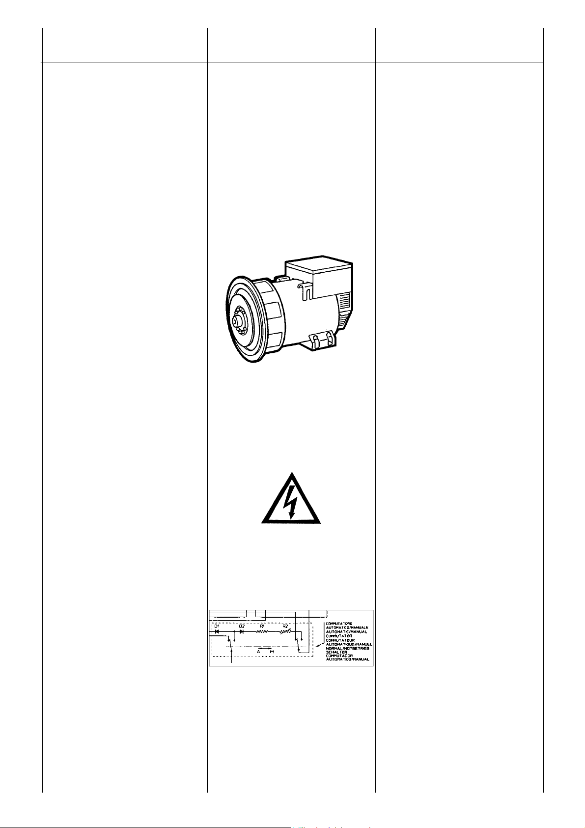
ACCOPPIAMENTO
ELETTRICO
ELECTRICAL
CONNECTIONS
IMPORTANTE
Nel funzionamento normale del generatore
deve essere acceso solamente il led verde.
Tutte queste segnalazioni possono essere
remotate a distanza e manipolate per usi
diversi tramite l’utilizzo del dispositivo
chiamato SPD96/A, disponibile a richiesta.
CAUSE CHE PROVOCANO
L’INTERVENTO DELLE
PROTEZIONI.
Intervento istantaneo protezione
bassa velocita’:
1 - velocita’ ridotta del 10% rispetto ai dati
di targa.
Intervento ritardato protezione
sovraccarico :
2 - sovraccarico del 20% rispetto ai dati di
targa.
3 - fattore di potenza (cos ϕ) inferiore ai dati
di targa.
4 - temperatura ambiente oltre i 50°C.
Intervento di entrambe le protezioni:
5 - combinazione del fattore 1 con i
fattori 2, 3, 4.
Nel caso di intervento delle protezioni, la
tensione erogata dall’alternatore scendera’
fino ad un valore che dipendera’ dall’entita’
dell’anomalia.
La tensione tornera’ automaticamente al suo
valore nominale qualora venga a cessare
l’inconveniente.
Per maggiori dettagli sui regolatori consultare il manuale specifico.
OPTIONALS :
Tutti gli alternatori della serie ECO-ECP
possono anche funzionare con regolazione
manuale, senza l’ausilio di sorgenti esterne
ma con il solo utilizzo di un reostato (tav. 1011 pag. 65).
IMPORTANT
In normal functioning, only the green led has
to be lit.
All these indicators can be remotely
controlled and adjusted, for any type of use,
by utilizing the SPD96/A accessory which is
available on request.
INTERVENTION OF PROTECTION
DEVICES CAUSES.
Underspeed protection
instantaneous intervention :
1 - speed reduced by 10% of nominal RPM
Delayed intervention of overload
protection :
2 - overload by 20% of nominal rating.
3 - power factor (cos ϕ) lower than the
nominal-one.
4 - ambient temperature above 50°C.
Intervention of both protections :
5 - combination of factor 1 with
factors 2, 3, 4.
In case of intervention the output voltage will
drop down to a value which will depend on
the fault.
The voltage will return automatically to its
nominal value as soon as the fault is
removed.
For further details on regulators, please see
the specific manual.
OPTIONALS :
All ECO-ECP series alternators can function
with manual regulation, without assistance
from any external source, by using a
rheostat (tab. 10-11 pag. 65).
26
ECO-ECP MANUAL September 2012 revision 32
Page 27

RACCORDEMENT
ELECTRIQUE
ELEKTRISCHER
ANSCHLUSS
CONEXION
ELECTRICA
IMPORTANT
En fonctionnement correct seule la led verte
doit être allumée.
Toutes ces protections peuvent être lues à
distance, ou utilisées pour tous signaux, à
travers notre SPD96/A disponible sur
demande.
CAUSES QUI PROVOQUENT
L’INTERVENTION DE LA
PROTECTION.
Intervention instantanée de la
protection sous-vitesse :
1 - vitesse réduite de 10% par rapport à
celle affichée.
Intervention retardée de la
protection surcharge :
2 - surcharse de 20% par rapport à la
plaque.
3 - facteur de puissance (cos ϕ) inférieur à
la plaque.
4 - température ambiante supérieure à
50°C.
Intervention de toutes les
protections :
5 - combinaison des facteurs 1
avec 2, 3 et 4.
Dans ce cas la tension de la machine
diminuera jusqu’à une valeur qui dépendra
de l’entité de l’anomalie.
La tension reviendra automatiquement à sa
valeur nominale lorsque cessera la cause du
problème.
Pour plus de détails sur les régulateurs,
consulter le manuel spécifique.
OPTIONS :
Tous les alternateurs de la série ECO-ECP
peuvent également fonctionner en régulation
manuelle, sans intervention externe, mais
avec seulement l’utilisation d’un rhéostat
comme montré sur les tableaux (tab. 10-11
pag. 65).
WICHTIG
Bei Normalbetrieb muß ausschliesslich die
grüne Leuchtdiode leuchten.
Die genannten Anzeigen sind für den
Femübertragung vorgesehen und können
auf dem Zusatzgerät Typ SPD96/A (lieferbar
auf besondere Bestellung) sichtbar gemacht
werden.
STÖRUNGEN, DIE ZUM AUSLÖSEN
DER SCHUTZEINRICHTUNGEN
FÜHREN.
Unverzögertes Ansprechen des
Unterdrehzahzahlschutzes :
1 - Auslösung bei 10% under
Nenndrehzahl gemäß Typenschild.
Verzögertes Ansprechen des
Überlast schtzes, Auslösung bei :
2 - 20% Überlast im Vergleich mit
Angaben auf dem Typenschild.
3 - Leistungsfaktor cosphi (cos ϕ) kleiner
als Nennleistungsfaktor gemäß
Typenschild.
4 - Umgebungstemperatur größer 50°C.
Ansprechen beider
Schtzeinrichtungen :
5 - Kombination der Ursache 1 mit 2,
3 und 4.
Sofen Unterdrehzahl und eine oder mehrere
Ursachen für das Ansprechen des Überlastschutzes auftreten, wird die Erregerspannung auf einen Wert zurückgeregelt,
der vom Ausmaß der Fehlerur-sachen
abhängt. Sobald die Störung beseitigt ist,
kehrt die Spannung auf den Nennwert
zurück.
Für weitere Einzelheiten bezüglich der
Regler, schlagen Sie bitte in dem
entsprechenden Handbuch nach.
NOTBETRIEB :
Bei Reglerausfall können die Generatoren
der Baureihe ECO-ECP gemäß Schaltplan
Abb. 10-11 S.65 ohne Hilfsstromquelle,
jedoch mit einem Vorwiderstand und 2
Dioden, betrieen werden.
IMPORTANTE
En el funcionamiento normal del generador,
deberá encenderse solo el led verde. Todas
estas señalaciones se pueden llevar a
distancia, y ser manipuladas en diversas
aplicaciones por medio del dispositivo
llmado SPD96/A, disponibile a pedido.
CAUSAS QUE PRODUCEN LA
INTERVENCION DE LAS
PROTECCIONES.
Intervención instantanea,
protección baja velocidad :
1 - velocidad reducida del 10% con relación
a los datos de tarjeta.
Intervento retardado, protección de
sobrecarga :
2 - sobrecarga del 20% respecto a los
datos de tarjeta.
3 - factor de potencia (cos ϕ) inferior a los
datos de tarjeta.
4 - temperatura ambiente superior 50 °C.
Intervención de ambas
protecciones:
5 - combinación del factor 1 con los
factores 2, 3, 4.
En el caso de intervención, la tensión
suministrada por el alternador descenderá
hasta un valor que dependerá de la entidad
del problema.
La tension volverá automáticamente a su
valor nominal en el momento cese el
inconveniente.
Para mayor información sobre los reguladores, consultar el manual especifico.
OPCIONALES :
Todos los alternadores de la serie ECOECP pueden también funcionar con la
regulación manual, sin el auxilio de fuentes
externas, con la simple utilización de un
reóstato (tab. 10-11 pag. 65).
27
ECO-ECP MANUAL September 2012 revision 32
Page 28
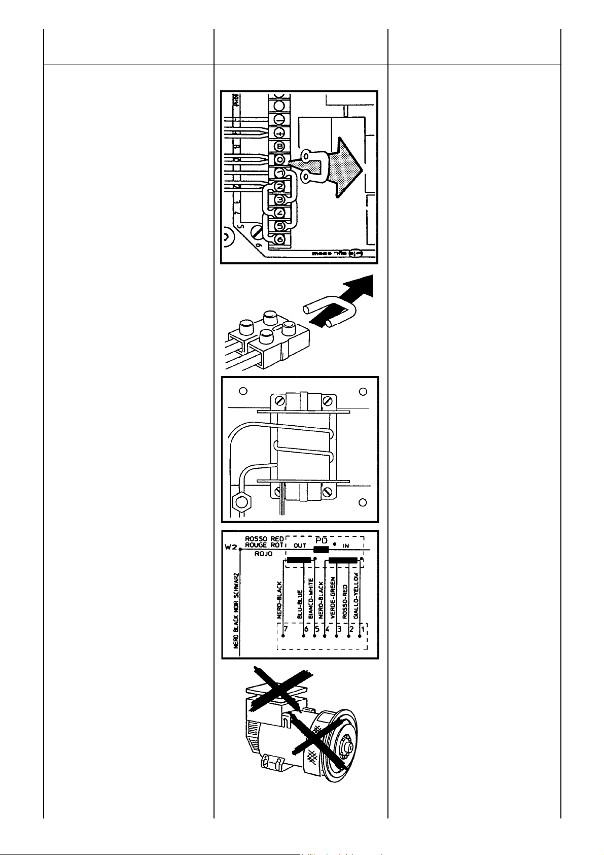
ACCOPPIAMENTO
ELETTRICO
ELECTRICAL
CONNECTIONS
FUNZIONAMENTO IN PARALLELO
Nel caso si voglia far funzionare dei generatori in parallelo e’ necessario montare un
dispositivo che assicura un identico statismo
sulla caretteristica esterna.
Questo significa che se le macchine lavorassero separatamente si avrebbe una
uguale caduta di tensione (circa 4%)
passando da vuoto a pieno carico.
Questo dispositivo e’ montato di serie sulle
grandezze 40 - 43 - 46, per cui, quando due
o piu’ di queste macchine devono lavorare in
parallelo e’ sufficiente togliere il ponticello
che cortocircuita il secondario del dispositivo
di parallelo.
Per le grandezze inferiori il dispositivo viene
montato a richiesta o puo’ essere montato
(ad eccezione del tipo ECP28/4) dal cliente
stesso secondo le tav.14-16-18-20. Dopo
aver montato il dispositivo e’ necessario
verificare l’esatto collegamento; si dovra’
controllare cioe’ che le macchine lavorando
singolarmente presentino una caduta di
tensione di circa il 4% passando, a velocita’
nominale e cos ϕ 0.8, da vuoto a pieno
carico.
MONTAGGIO DI UN DISPOSITIVO
DI PARALLELO
Riferendosi alle tavole 14-16-19 montare il
trasformatore di parallelo come illustrato.
Collegare le spire di potenza in serie alla
fase.
Il numero delle spire da eseguire sul
trasformatore saranno indicate sulle
istruzioni allegate al trasformatore stesso.
Il secondario del trasformatore di parallelo va
connesso in serie al riferimento del
regolatore elettronico come mostrato nelle
tavole 4 e 5 pag. 61.
Per abilitare il dispositivo di parallelo rimuovere il ponticello che cortocircuita il secondario del dispositivo stesso come mostrano
gli schemi sopra indicati.
NOTA
Alla richiesta del dispositivo di parallelo e’
indispensabile conoscere i dati nominali
dell’alternatore su cui andra’ applicato.
Dopo aver eseguito tutti i collegamenti
elettrici e solo dopo aver chiuso tutte le
protezioni e’ possibile effettuare la prova di
primo avviamento del sistema.
PARALLEL OPERATION
Should the alternators be required to operate
in parallel, it is necessary to add a paralleling
device to ensure equal droop of generator
output voltages.
This ensures that if the machines are
operated separately, the voltage droop (4%
approx.) is equal when switching from noload to full load.
The parallel device is fitted as standard on
40-43-46 models, therefore when two or
more of these units must function in parallel,
it is sufficient to remove the bridge which
shortcircuits the secondary winding of the
parallel device.
On smaller models this device is mounted
on request or it can be added (except for
ECP28/4) by the client himself following the
instructions of tables 14-16-18-20.
After the device has been mounted, check
whether the connection has been properly
made; make sure that there is a voltage drop
of approximately 4% in the machines when
they function individually switching at rated
speed and cos ϕ 0.8 from no-load to full load
operation.
HOW TO MOUNT THE PARALLEL
DEVICE
Referring to tables 14-16-19 mount parallel
device as indicated.
Connect the power turns in series with
phase. The numbers of turns to be wound
on the transformer will be indicated in the
instruction accompanying the transformer
itself. The secondary winding of the parallel
transformer must be connected in series to
the sensing of the electronic regulator as
shown on tables 4 - 5 page 61.
In order to activate the parallel device
remove the bridge which shortcircuits the
secondary winding of the device itself as
shown in the above mentioned tables.
NOTE
When requesting a parallel device, it is
necessary to indicate the nominal data of the
alternator on which the device will be
applied.
After all the electric connections have been
made and only after all the protections
have been put in place, can the system be
started.
28
ECO-ECP MANUAL September 2012 revision 32
Page 29

RACCORDEMENT
ELECTRIQUE
ELEKTRISCHER
ANSCHLUSS
CONEXION
ELECTRICA
FONCTIONNEMENT EN PARALLELE
Dans le cas ou l’ou veut faire fonctionner les
alternateurs en parallèle, il est nécessaire de
monter un dispositif qui assure un statisme
identique sur les caractéristiques externes.
Ceci signifie que si les machines
fonctionnaient séparément, on aurait une
chute égale de tension (environ 4%) en
passant de vide à pleine charge.
Ce dispositif est monté en série sur les
grandes puissances 40-43-46, pour
lesquelles, lorsque 2 ou plus de ces
machines doivent fonctionner en paralléle, il
est nécessaire de supprimer le pont qui
court-circuite le secondaire du dispositif.
Pour les puissances inférieures, le dispositif
peut être monté (à l’exception du type
ECP28/4) sur demande du client suivant les
tab. 14-16-18-20.
Après avoir mis en place le dispositif, il est
nécessaire de vérifier l’exactitude des
connections, il faudra donc contrôler que
chaque machine présente une chute de
tension de l’ordre de 4% en étant à la vitesse
nominale pour un cos ϕ 0.8 de vide à pleine
charge.
MONTAGE DU DISPOSITIF
DE PARALLELE
Monter le dispositif de parallèle comme
illustré tableaux 14-16-19.
Connecter la spire de puissance en série
avec la phase.
Le nombre de spires à positionner, sur le
transformateur sera indiqué avec les
instructions fournies avec le transformateur.
Le secondaire du transformateur de
parallèle est connecté en serie à la référence
du régulateur électronique comme indiqué
sur les tableaux 4 et 5 pag. 61.
Il est également nécessaire de supprimer le
pont qui court circuite le secondaire du
dispositif comme montré ci-après.
N.B.
Lorsque vous commandez à posteriori le
dispositif de parallèle il nous est
indispensable de connaître les informations
de la notre plaque constructeur.
Aprés avoir exécuté tous les raccordements
électriques et seulement après avoir
contrôlé le fonctionnement de toutes les
protections, il est possible d’effectuer l’essai
de la première mise en marche du système.
PARALLELBETRIEB
Sollen die Generatoren im Parallelbetrieb
arbeiten, ist es erforderlich, ein Gerät zu
montieren, das nach außen die gleiche
Regelgüte garantiert.
Dies bedeutet, daß bei separatem Betrieb
der Maschinen und beim Wechsel vom
Leerlauf auf Vollast, ein gleicher
Spannungsabfall erzielt würde (etwa 4%).
Diese Vorrichtung ist serienmäßig in den
Größen 40 - 43 - 46 montiert; aus diesem
Grund ist es ausreichend, die Brücke, die
Sekundärwicklung der Parallelvorrichtung
kurzschließt, zu entfernen, wenn zwei oder
mehrere dieser Maschinen parallel arbeiten
müssen .
Für geringere Größen kann diese
Vorrichtung auf Anfragen ebenfalls
aufmontiert werden, bzw. der Kunde kann
diese selbst, unter Berücksichtigung der
Angaben in den Tabellen 14-16-18-20
montieren (mit Ausnahme von Typen
ECP28/4). Nach Montage dieser
Vorrichtung ist es erforderlich, den korrekten
Anschluß zu überprüfen. Es ist zu
kontrollieren, ob die Maschinen, wenn sie im
Einzelbetrieb laufen, beim Wechsel vom
Leerlauf auf Vollast, bei
Nominalgeschwindiigkeit und
Leistungsfaktor von 0.8 einen
Spannungsabfall von etwa 4% aufweisen.
MONTAGE DES STATIKWANDLERS
Den Statikwandler so montieren wie
auf den Abbiildungen 14 bzw. 16-19
dargestellt.
Die Primärwicklung ist in Reihe mit der
Wicklung zu schalten. Die Anzahl der auf
dem Statikwandler anzubringenden
Windungen, ist den Anweisungen zu
diesem zu entnehmen.
Die Sekundärwicklung des Statikwandlers
wird gemäß Abbildungen 4 bzw. 5 Seite 61
mit dem Istwertdraht des elektronischen
Regler Reihengeschaltet.
Damit der Statikwandler wirksam wird, muß
die Brücke entfernt werden, wie in Abb. 4
bzw. 5 gezeigt.
ANMERKUNG
Bei Bestellung des Statikwandlers sind die
Nennwerte des Generatores anzugeben, für
den dieser bestimmt ist.
Nachdem alle elektrischen Anschlüsse
ansgeführt und nur nachdem alle
Schutzvorrichtungen geschlossen
wurden, ist es möglich, die Prüfung eines
ersten Systemstarts durchzuführen.
FUNCIONAMIENTO EN PARALELO
Es necesario montar un dispositivo que
asegura un estatismo idéntico sobre la
caracteristica exsterna, para que las
máquinas puedan funcionar en paralelo
entre ellas. Esto significa que si las
máquinas trabajarán separadamente, se
tendría una igual caída de tensión (aprox.
4%) pasando de vacío a plena carga.
Este dispositivo viene montado de serie a
partir del tamaño 40 - 43 y 46, por lo que
cuando dos ó más de estas máquinas
deban trabajar en paralelo es suficiente
quitar el puentecillo che cortocircuita el
secundario del dispositivo de paralelo.
Para los tamaños inferiores el dispositivo se
monta bajo pedido, o puede ser montado
(excepto el tipo ECP28/4) por el propio
cliente siguiendo las instrucciones según el
display de las tablas 14-16-18-20. Después
de haber montado el dispositivo, es
necesario verificar el exacto conexionado;
debiéndose controlar que la máquina
funcionando por separado presente una
caída de tensión de apróximadamente el
4% pasando, a velocidad nominal y cos ϕ
0.8, de vacío a plena carga.
MONTAJE DEL DISPOSITIVO
DE PARALELO
Como se muestra a las tablas 14-16-19
montar el transformador de paralelo como
viene ilustrado.
Conectar la espira de potencia en serie a la
fase. El número de las espiras a insertar
sobre el transformador están indicadas
sobre las instrucciones agregadas al mismo
transformador.
El secundario del transformador de paralelo
va conectado en serie a la referencia del
regulador electrónico como se muestra en
las tablas 4 y 5 pag. 61. Para habilitar el
dispositivo de paralelo quitar el puenticillo
que cortocircuita el secondario del mismo
dispositivo como muestra el esquema arriba
indicado.
NOTA
Cuando se solicita el dispositivo de paralelo
es indispensabile conocer los datos
nominales del alternador sobre el cual será
aplicado.
Después de haber realizado todas las
conexiones eléctricas y “solo después de
haber cerrado todas las protecciones” es
posible efectuar el primer arranque del
sistema.
29
ECO-ECP MANUAL September 2012 revision 32
Page 30
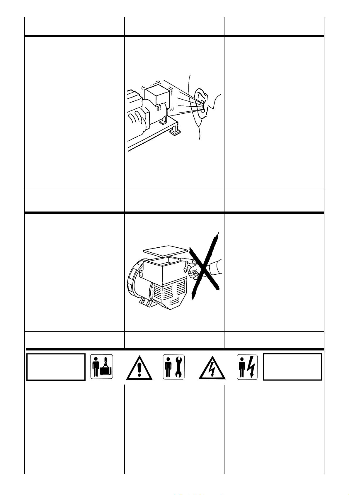
AVVIAMENTO
E ARRESTO
STARTING AND
STOPPING OPERATIONS
La strumentazione per l’avviamento, la
conduzione e l’arresto del sistema e’ a carico
dell’installatore.
LE OPERAZIONI DI AVVIAMENTO,
CONDUZIONE E ARRESTO DEVONO
ESSERE ESEGUITE DA PERSONALE
ADEGUATAMENTE QUALIFICATO E
CHE ABBIA LETTO E COMPRESO LE
PRESCRIZIONI DI SICUREZZA
ALL’INIZIO DEL MANUALE.
IMPORTANTE :
Durante il primo avviamento, che deve
essere eseguito a velocita’ ridotta,
l’installatore dovra’ verificare che non si
presentino rumori anomali.
In caso di rumori anomali provvedere a
fermare immediatamente il sistema e
intervenire per migliorare l’accoppiamento
meccanico.
PULIZIA
E LUBRIFICAZIONE
All the instrumentation for starting, running
and stopping the system shall be provided by
the installer.
THE STARTING, RUNNING AND
STOPPING OPERATIONS MUST BE
CARRIED OUT BY SKILLED
PERSONNEL WHO HAVE READ AND
UNDERSTOOD THE SAFETY
INSTRUCTIONS AT THE BEGINNING
OF THIS MANUAL.
IMPORTANT :
When the system is set to work for the first
time, which has to be done at a reduced
speed, the operator shall check that no
anomalous noises can be detected.
If an anomalous noise is detected, stop the
system immediately and improve the
mechanical coupling.
CLEANING
AND LUBRICATION
Prima di avvicinarsi al generatore assicurarsi
che sia a stato energetico zero e a
temperatura ambiente; a questo punto e’
possibile pulirlo esternamente con aria
compressa.
NON UTILIZZARE MAI LIQUIDI O
ACQUA.
NON PULIRE CON ARIA COMPRESSA LE
PARTI ELETTRICHE INTERNE, POICHE’
POSSONO VERIFICARSI
CORTOCIRCUITI O ALTRE ANOMALIE.
Per la lubrificazione dei cuscinetti consultare
la tabella 23 pag. 71.
MANUTENZIONE
PERICOLO
DANGER
I generatori della serie ECO-ECP sono
costruiti per lavorare a lungo senza
manutenzione.
PRIMA DI ESEGUIRE QUESTA
OPERAZIONE LEGGERE MOLTO
ATTENTAMENTE LE PRESCRIZIONI
DI SICUREZZA ALL’INIZIO DI
QUESTO MANUALE.
Prior to approaching or touching the
alternator, ensure that it is not live and it is at
room temperature; at this stage it is possible
to clean it on the outside using compressed
air.
NEVER USE LIQUIDS OR WATER.
DO NOT CLEAN THE INSIDE
ELECTRIC COMPONENTS WITH
COMPRESSED AIR, BECAUSE THIS
MAY CAUSE SHORT-CIRCUITS OR
OTHER ANOMALIES.
For the lubrication of bearings, see table 23
on page 71.
MAINTENANCE
GEFAHR
PELIGRO
The alternators series ECO-ECP are
designed to give a long maintenance free
working life.
BEFORE PERFORMING THIS
OPERATION, READ THE SAFETY
REQUIREMENTS AT THE
BEGINNING OF THIS MANUAL
CAREFULLY.
30
ECO-ECP MANUAL September 2012 revision 32
Page 31

DEMARRAGE
ET ARRET
ANTRIEB
UND STILLSETZUG
ARRANQUE
Y PARADA
La manipulation pour le démarrage, le
fonctionnement et l’arrêt est à la charge de
l’installateur.
LES OPERATIONS DE
DEMARRAGE, FONCTIONEMENT ET
ARRET DOIVENT ETRE FAITES PAR
DU PERSONNEL QUALIFIE AYANT
LU ET COMPRIS LES
PRESCRIPTIONS DE SECURITE AU
DEBUT DU MANUEL.
IMPORTANT :
Durant le premier démarrage, qui doit être
exécuté à vitesse réduite, l’installateur doit
vérifier qu’aucun bruit anormal ne se
présente.
Dans le cas de bruits anormaux, interrompre
immédiatement le fonctionnement et vérifier
l’accouplement mécanique.
NETTOYAGE
ET GRAISSAGE
Die Instrumentierung für Antrieb, die
Netzführung und die Stillsetzung der
Systeme obliegt dem Monteur.
ANTRIEB, NETZFÜHRUNG UND
STILLSETZUNG DÜRFEN AUSSCHLIEßLICH
VON ENTSPRECHEND QUALIFIZIERTEN
FACHPERSONAL DURCHGEFÜHRT
WERDEN UND ZWAR ERST NACHDEM DIE
SICHERHEITSVORSCHRIFTEN AM ANFANG
DIESES HANDBUCHS GELESEN UND
VERSTANDEN WORDEN SIND.
WICHTIG :
Während der ersten Inbetriebnahme, die mit
reduzierter Geschwindigkeit erfolgen muß,
hat der Monteur zu überprüfen, ob
Anomalien in der Geräuschentwicklung
auftreten. Im Falle von Anomalien in der
Geräuschentwicklung, ist dafür zu sorgen,
daß die Anlage unverzüglich gestoppt wird.
Die mechanischen Anschlüsse müssen in
diesem Falle verbessert werden.
REINIGUNG
UND SCHMIERUNG
La instrumentación para el arranque, la
conducción y la parada del sistema es a
cargo del instalador.
LAS OPERACIONES DE ARRANQUE,
CONDUCCION Y PARADA DEBEN
SER REALIZADAS POR PARTE DE
PERSONAL ADECUADAMENTE
CALIFICADO Y QUE HAYA LEIDO Y
COMPRENDIDO LAS NORMAS DE
SEGURIDAD AL PRINCIPIO DEL
MANUAL.
IMPORTANTE :
Durante el primer arranque, que deberá
efectuarse a baja velocidad, el instalador
deberá controlar que no se presenten
rumores anormales.
En caso de rumores anormales, detener
inmediatamente el sistema e intervenir para
mejorar el acoplamiento mecánico.
LIMPIEZA
Y LUBRIFICACION
Avant tout contact avec l’alternateur,
s’assurer de sa propreté parfaite et qu’il soit à
température ambiante; il est alors possible
de le nettoyer exterieurement avec de l’air
comprimé.
NE JAMAIS UTILISER DE LIQUIDE
OU DE L’EAU.
NE PAS NETTOYER AVEC DE L’AIR
COMPRIME LES PARTIES
ELECTRIQUES INTERNES, CAR L’ON
POURRAIT PROVOQUER UN COURTCIRCUIT OU AUTRES ANOMALIES.
Pour le graissage des roulements, consulter
le tableau 23 pag. 71.
MAINTENANCE
PERICOLO
DANGER
Les alternateurs de la série ECO-ECP sont
construits pour fonctionner longtemps sans
aucun entretien.
AVANT D’EXECUTER CETTE OPERATION, LIRE ATTENTIVEMENT LES PRESCRIPTIONS DE SECURITE AU DEBUT
DU MANUEL.
Bevor Sie sich dem Generator nähern, ist
sicherzustellen, daß dieser nicht mehr
stromführend ist und sich auf Raumtemperatur abgekühlt hat; zu diesem
Zeitpunkt ist es möglich, den Generator von
außen mit Preßluft zu reinigen.
NIEMALS FLÜSSIGREINIGER ODER
WASSER VERWENDEN.
DIE INNENLIEGENDEN
ELEKTROTEILE NIEMALS MIT
PRESSLUFT REINIGEN, DA SICH
KURZSCHLÜS-SE ODER ANDERE
STÖRUNGEN DARAUS ERGEBEN
KÖNNTEN.
Bezüglich der Schmierung der Lager sind die
Angaben in Tabelle 23, Seite 71 zu befolgen.
WARTUNG
Die Generatoren der Serie ECO-ECP sind
so konstruiert, daß sie einen langen Zeitraum
ohne Wartung arbeiten können.
BEVOR DIESE ARBEITEN
DURCHGEFÜHRT WERDEN, SIND DIE
AM ANFANG DIESES HANDBUCHES
ANGEGEBENEN
SICHERHEITSVORSCHRIFTEN
AUFMERKSAM ZU LESEN.
31
Antes de acercarse al generador, asegurarse que el mismo sea a estado
energético cero y a temperatura ambiente;
en estas condiciones es posible limpiarlo
externamente con aire comprimido.
NO UTILIZAR NUNCA LIQUIDOS O
AGUA.
NO LIMPIAR CON AIRE
COMPRIMIDO LAS PARTES
ELECTRICAS INTERNAS, DEBIDO A
LA POSIBILIDAD DE CAUZAR
CORTOCIRCUITOS O CUALQUIER
OTRO TIPO DE PROBLEMA.
Para la lubrificación de los cojinetes consultar
la tabla 23 pag. 71.
MANTENIMIENTO
GEFAHR
PELIGRO
Los generadores de las series ECO-ECP
son construidos para trabajar por mucho
tiempo sin mantenimiento.
ANTES DE REALIZAR DICHA
OPERATION LEER
CUIDADOSAMENTE LAS NORMAS
DE SEGURIDAD AL PRINCIPIO DE
ESTE MANUAL.
ECO-ECP MANUAL September 2012 revision 32
Page 32

MANUTENZIONE MAINTENANCE
Gli interventi di manutenzione sul
generatore Mecc Alte si possono
dividere in ordinari e straordinari; in ogni
caso qualsiasi intervento deve essere
autorizzato dal responsabile della
sicurezza, a macchina ferma e isolata
elettricamente dall’impianto o dalla rete.
La manutenzione e la ricerca guasti
deve essere eseguita da personale
elettricamente/meccanicamente
qualificato in quanto ogni operazione a
seguito descritta presenta pericoli per il
personale.
Si raccomanda inoltre che siano prese
tutte le precauzioni per impedire che la
macchina venga riavviata inavvertitamente durante le fasi di manutenzione e ricerca guasti.
Gli interventi di manutenzione ordinaria
possono essere riassunti in :
a) verifiche condizioni avvolgimenti
dopo lunghi periodi di immagazzinamento o di sosta
b) verifiche, ad intervalli regolari, del
corretto funzionamento (assenza di
rumori o vibrazioni anomale)
c) verifiche meccaniche su tutti i bulloni
di fissaggio ed in particolare delle
connessioni elettriche
d) pulizia esterna del generatore
a) Verifiche condizioni avvolgimenti
dopo lunghi periodi di immagazzinamento o di sosta.
La condizione degli avvolgimenti può
essere verificata mediante la misura
della resistenza di isolamento verso
terra. Tale misura si esegue con uno
strumento “Megger” o similari a 500V di
tensione continua; è importante che
prima di eseguire la prova, il regolatore
di tensione (fig. a), il ponte diodi rotante
(fig. b), i filtri anti disturbi radio (fig. c) e
tutti gli eventuali dispositivi connessi
elettricamente agli avvolgimenti da
verificare, vengano scollegati.
fig. a
fig. b
fig. c
Maintenance operations on Mecc Alte
generators can be divided into routine
and extraordinary maintenance
operations; in both cases, all
operations must be authorised by the
safety representative and they must be
carried out when the machine is turned
off and insulated from the electric
installation or from the power mains.
High-qualified mechanical or electrical
technicians must carry out
maintenance operations and any fault
search since all operations described
hereunder could put personnel in
serious danger.
It is also highly recommended to take
all the necessary precautions so as to
prevent an inadvertent starting of the
machine during maintenance and fault
search operations.
Routine maintenance operations can
be summed up as follows:
a) Assessment of windings conditions
after long periods of storage or
inactivity
b) Assessment, on a regular basis, of
correct functioning (absence of
anomalous noises or vibrations)
c) Mechanical inspections on all
fastening bolts and, in particular, on
electric connections
d) external cleaning of generator
a) Assessment of windings
conditions after long periods of
storage or inactivity.
Measuring the insulating earth
resistance can assess the condition of
the windings. This measurement can
be carried out with a “Megger” device,
or similar, with a 500V direct-current
voltage. It is very important to
disconnect the voltage regulator (fig.
a), the rotating diode bridge (fig. b) and
the radio-interference filter (fig. c), as
well as any other device connected to
the windings to be checked, before
carrying out the measurement.
32
ECO-ECP MANUAL September 2012 revision 32
Page 33

MAINTENANCE WARTUNG MANTENIMIENTO
Les interventions de maintenances sur
les alternateurs Mecc Alte peuvent être
considérées comme ordinaires ou extra
-ordinaires ; dans chaque cas toute
intervention doit être autorisée par le
responsable de la sécurité, et effectuée
sur une machine arrêtée et isolée
électriquement de l’installation ou du
réseau.
La maintenance et le recherche de
panne doit être effectuée par du
personnel électriquement/
mécaniquement qualifié car chaque
opération décrite ci-dessous présente
des dangers pour l’utilisateur.
Nous recommandons en outre que
soient prises toutes les précautions
pour empêcher le redémarrage du
groupe par inadvertance durant les
phases de maintenances et de
recherche de pannes.
Les interventions de maintenances
ordinaires peuvent être résumées
ainsi :
a) Vérification des enroulements
après de longues périodes
d’emmagasinement ou d’arrêt de
fonctionnement.
b) Vérification, à intervalles réguliers,
du fonctionnement correct
(absence de bruit ou vibrations
anormales).
c) Vérifications mécaniques de tous
les boulons de fixations et en
particulier des connexions
électriques.
d) Nettoyage externe de l’alternateur.
a) Vérification des enroulements
après de longues périodes
d’emmagasinement ou d’arrêt de
fonction-nement :
L’état des enroulements peut être
vérifier par la mesure de la résistance
de l’isolement vers la masse ou terre.
Telle mesure s’effectue par un
instrument “Megger” ou un matériel
similaire à 500V de tension en
continue. Il est important que, avant
d’effectuer l’essai, le régulateur de
tension (fig. a), le pont de diodes
tournantes (fig. b), les filtres antiparasitage ( fig. c) et tous les éventuels
dispositifs de connexions électriques
aux enroulements à vérifier, ne soient
pas connectés.
Die Wartungsarbeiten an dem
Stromerzeuger Mecc Alte Spa können in
normale und ausserordentliche geteilt
werden; auf jeden Fall muss jede
Wartung von dem
Sicherheitsverantwortlichen authorisiert
werden; das kann nur passieren wenn
die Maschine unbeweglich und
elektrisch von der Anlage oder von dem
Netz isoliert wird.
Die Wartung und die Schadenuntersuchung muss von den
elektrischen/mechanischen Fachkräften
getan werden,denn jede Operation,
welche unten beschrieben wird, zeigt
besondere Gefahren für das
Dienstpersonal.
Es wird streng empfohlen, alle
Vorsichtsmassnahmen zu treffen, um zu
verhindern,dass die Maschine
versehentlich während der Wartung und
der Schadenuntersuchung wieder
angelassen wird.
Die normalen Wartungsarbeiten können
wie folgt zusammengefasst werden.
a) Nachprüfungen der
Wicklungswiderstände nach
längeren Zeiten von Einlagerung
oder Stillstand
b) Nachprüfungen in regelmässigen
Zeitabständen, der richtigen
Arbeitsweise (Abwesenheit von
Laermen oder anomalen
Vibrationen)
c) Mechanische Nachprüfungen über
alle Befestigungsbolzen und
besonderes über die elektrischen
Verbindungen.
d) Innerliche Reinigung des
Stromerzeugers
a) Nachprüfungen der
Wickelkbedingungen nach längeren
Zeiten von Einlagern oder Stillstand.
Die Wickelbediengungen können durch
die Messung des
Erdeisolierungwiderstands überprüft
werden.
Diese Messung wird durch ein
Instrument genannt Megger oder durch
einige ähnliche Instrumente mit 500V
Prüfspannung ausgeführt; es ist ganz
wichtig dass, bevor die Probe getan
wird, der Spannungsregler (abb. a), die
rollende Diodebrücke (abb. b), die
Funkentstör-Filter (abb. c) und alle
andere eventuelle Vorrichtungen,welche
mit den überprüfenden Wicklungen
elektrisch verbunden sind,
ausgeschaltet werden.
Las intervenciones de manutención en
el generador Mecc Alte se pueden
dividir en ordinarias y extraordinarias;
de cualquier forma, todas las
intervenciones deben ser autorizadas
por el responsable de la seguridad, con
la máquina parada y aislada
electricamente de la instalación o de la
red.
La manutención y la búsqueda de
averías deben ser hechas por personal
electricamente/mecánicamente
cualificado, ya que cada operación a
seguir descrita presenta peligros para el
personal.
Se recomienda además que sean
tomadas todas las precauciones para
impedir que la máquina vuelva a
funcionar inadvertidamente durante las
fases de manutención y búsqueda de
averías.
Las intervenciones de manutención
ordinaria pueden ser resumidas en:
a) verificaciones de condiciones de
envoltura después de largos
periodos de almacenaje o de pausa
b) verificaciones, a intervalos
regulares, del correcto
funcionamiento (ausencia de ruidos
o vibraciones anómalas)
c) verificaciones mecánicas en todos
los pernos de fijación y en
particular de las conexiones
eléctricas
d) limpieza externa del generador.
a) Verificación de condiciones de
envoltura después de largos
periodos de almacenaje o de pausa.
La condición de las envolturas puede
ser verificada por la medición de la
resistencia de aislamiento a la tierra.
Tal medición se lleva a cabo con un
instrumento “Megger” o similares a
500V de tensión continua; es
importante que antes de hacer la
prueba, el regulador de tensión (fig. a),
el puente diodos rotativo (fig. b), los
filtros anti-disturbio radio (fig. c) y todos
los eventuales dispositivos conectados
electricamente a las envolturas
verificadas, sean desconectados.
33
ECO-ECP MANUAL September 2012 revision 32
Page 34

MANUTENZIONE MAINTENANCE
Il valore misurato di resistenza verso
terra di tutti gli avvolgimenti deve essere
superiore a 1MΩ.
Nell’ipotesi in cui il valore misurato sia
inferiore a quanto sopra riportato, gli
avvolgimenti devono essere opportunamente asciugati. Tale operazione
può essere eseguita indirizzando un
getto di aria calda a circa 50-60°C, negli
ingressi o nelle uscite dell’aria del
generatore.
In alternativa a quanto sopra, gli
avvolgimenti di statore possono essere
collegati elettricamente e fatti
attraversare da una corrente mediante
un alimentatore in continua; il valore di
corrente da fare circolare negli
avvolgimenti dipenderà dalle dimensioni
dell’alternatore e comunque dovrà
essere stabilito in accordo ai valori
nominali riportati nella targhetta.
b) Verifiche del corretto funzionamento (assenza di rumori o vibrazioni anomale).
Ad intervalli regolari raccomandiamo di
verificare che il generatore funzioni
regolarmente senza rumori o vibrazioni
anomale; tali presenze potrebbero
denotare il danneggiamento dei
cuscinetti.
Ricordiamo che l’alternatore a sé stante
non presenta vibrazioni particolari in
quanto le parti rotanti sono perfettamente bilanciate. Premesso che la
bilanciatura del rotore non sia stata
alterata e che i cuscinetti dell’alternatore
non siano danneggiati, le cause delle
vibrazioni presenti sul gruppo
elettrogeno saranno da ricercare negli
allineamenti degli accoppiamenti, nelle
sollecitazioni del motore termico o nei
supporti antivibranti.
Si raccomanda inoltre di verificare i dati
funzionali che devono risultare in linea
con quanto riportato nella targhetta del
generatore.
c) Verifiche meccaniche su tutti i
bulloni di fissaggio ed in particolare
delle connessioni elettriche.
Ad intervalli regolari raccomandiamo di
verificare che tutti i bulloni di fissaggio
siano adeguatamente stretti; una
particolare attenzione deve essere
rivolta alle connessioni elettriche,
operazione che deve essere eseguita
con la assoluta certezza di assenza di
tensione. Nel manuale del generatore
sono indicate le corrette coppie di
serraggio delle varie dimensioni di
bullone.
The figure resulting from the
measurement of the windings’ earth
resistance must be over 1MΩ.
Should the figure be smaller than the
above-mentioned one, the windings
must be adequately dried up. This can
be done by directing a jet of hot air of
about 50-60°C into the generator’s air
inlets or outlets; alternatively, the
stator’s windings can be electrically
connected and a voltage can be passed
through them by means of a directcurrent power supply. The amount of
current in the windings depends on the
generator size, even though it must be
fixed according to the nominal values
stated on the plate.
b) Assessment of current functioning
(absence of anomalous noises or
vibrations).
We recommend users to check
regularly the correct functioning of the
generator, and to verify that there are
no anomalous noises or vibrations; their
presence might indicate damage of
bearings.
May we remind you that the alternator
itself has no particular vibration since
the rotating parts are perfectly
balanced. Provided that the rotor
balancing has not been altered and that
the rotor’s bearings have not been
damaged, vibrations in the generator
set may occur due to alignments of
couplings, due to stress upon the
combustion engine, or to vibration
mounts.
We also recommend checking of
performance data which must comply
with the data on the generator’s plate.
c) Mechanical checks of fastening
bolts and, in particular, of electric
connections.
We recommend a regular check of all
fastening bolts, which must be perfectly
tightened up. Special attention should
be paid to all electric connections; this
inspection must be carried out in the
complete absence of voltage. To
choose the correct tightening wrenches
suitable for the different sizes of the
bolts, see generator manual.
34
ECO-ECP MANUAL September 2012 revision 32
Page 35

MAINTENANCE WARTUNG MANTENIMIENTO
La valeur mesurée de la résistance vers
la terre de tous les enroulements doit
être supérieure à 1 Mohm.
Dans l’hypothèse dans laquelle la
valeur mesurée soit inférieure à ce qui
était ci-dessus donné, les enroulements
doivent être bien secs.
Telle opération peut être exécutée en
dirigeant un jet d’air chaud à environ 50
-60 °C dans les entrées ou sorties d’air
de l’alternateur.
En alternative de ce qui est donné cidessus , les enroulements du stator
peuvent être court-circuités et traversés
par un courant au moyen d’un
alimentateur en continue; la valeur du
courant qui doit circuler dans les
enroulements dépend de la dimension
de l’alternateur et de toute manière
devra être stabilisée en accord aux
valeurs nominales reportées sur la
plaquette.
b) Vérification, à intervalles réguliers,
du fonctionnement correct (absence
de bruit ou de vibrations anormales).
A intervalles réguliers, nous
recommandons de vérifier que
l’alternateur fonctionne régulièrement
sans bruit ou vibration anormale. Tel
phénomène pourrait dénoter
l’endommagement des roulements.
Nous rappelons que l’alternateur ne
présente pas de vibrations particulières
lorsque les parties tournantes sont
parfaitement équilibrées.
En considérant que l’équilibrage du
rotor ne soit pas altéré et que les
roulements de l’alternateur ne sont pas
endommagés, les causes des vibrations
présentes sur le groupe électrogène
seront à rechercher dans les
alignements des accouplements, dans
les sollicitations du moteur thermique
ou dans les supports anti-vibrations.
Nous recommandons également de
vérifier les données fonctionnelles qui
doivent être en coordination avec ce qui
est reporté sur la plaque de
l’alternateur.
c) Vérifications mécaniques de tous
les boulons de fixations et en
particulier des connexions
électriques.
A intervalles réguliers, nous
recommandons de vérifier que tous les
écrous de fixation soient correctement
serrés; une attention particulière doit
être apportée aux connexions
électriques, opération qui doit être
suivie avec l’absolue certitude
d’absence de tension. Dans le manuel
de l’alternateur sont indiqués les
couples de serrage corrects de tous les
écrous de dimensions différentes.
Der gemesste Widerstandswert aller
Wicklungen gegen Erde muss
unbedingt mehr als 1MΩ sein.
In dem Fall, in dem der gemesste Wert
niedrieger ist im Vergleich zu was oben
gennant worden ist, muessen die
Wicklungen gelegentlich ausgetrocknet
werden.
Dieses Verfahren kann durch den Wurf
eines Strahles warmer Luft mit einer
Temperatur von 50-60 °C in die
Eingänge oder Ausgänge des
Stromzeugers ausgeführt werden.
Eine andere Möglichkeit zu o.g. wäre
die elektrischen Versogung der
Ständerwicklung. Sie könnte im Prinzip
durch einen Gleichstrom von einen
separaten Stromerzeugerzeuger mit
Strom durchflossen werden. Der
Stromwert, welcher in den Spulen sich
bewegen muss, hängt von den
Wechselstromgeneratorgrössen ab und,
darf auf keinen Fall die Nominalwerte
des Generators, wie sie auf dem Schild
erscheinen überschreiten.
b) Ueberprüfungen der richtigen
Arbeitsweise (Abwesenheit von
Lärmen oder anomalen
Schwingungen).
In regelmässigen Zeitabständen
empfehlen wir streng zu überprüfen,ob
der Stromerzeuger normal funktioniert,
ohne Lärme oder ausserordentliche
Schwingungen;die Anwesenheit solcher
Laerme koennte auf eine Beschädigung
der eingebauten Lager hindeuten. Wir
moechten Sie daran erinnern,dass der
Wechselstromgenerator selbst
normalerweise keine besondere
Schwingungen zeigt, weil die
rotierenden Teile perfekt balanciert
sind. Vorausgesetzt dass die Auswucht
nicht verändert worden ist und die
Lager des Wechselstromgenerators
nicht beschädigt sind, sind die Gründe
der Schwingungen auf dem Generator
in den Anreihungen der Verbindungen,
in den Schwingungen des AntriebsMotors oder in den AntischwingungsAuflagen zu finden.
Es wird auch empfohlen, die
Übereinstimmung der funktionellen
Daten mit den Daten vom Typenschild
des Genetors zu überprüfen.
c) Mechanische Ueberprüfungen
über alle Befestigungbolzen und
besonders über die elektrische
Verbindungen. In regelmässige
Zeitabstände empfehlen wir zu
überprüfen, ob die Befestigungsbolzen
angemessen fest sind; eine besondere
Aufmerksamkeit muss den elektrischen
Verbindungen gegeben werden. Diese
Handlung muss ausgefuehrt werden nur
wenn man absolut sicher ist, dass keine
Spannung vorhanden ist. Auf dem
Hinweisbuch des Stromerzeugers
werden die richtigen
Befestigungsmomente der
verschiedenen Groessen der Bolzen
mitgeteilt.
35
El valor medido de resistencia a la tierra
de todas las envolturas debe ser
superior a 1MΩ.
En la hipótesis de que el valor medido
sea inferior al arriba indicado, las
envolturas deben ser oportunamente
secadas. Tal operación puede ser
hecha direccionando un chorro de aire
caliente a aproximadamente 50-60°C,
en las entradas o en las salidas de aire
del generador.
Alternativamente al indicado arriba, las
envolturas de estator pueden ser
coligadas electricamente y ser
atravesadas por una corriente a través
de un alimentador en continuo; el valor
de corriente a hacer circular en las
envolturas dependerá de las
dimensiones del los alternadores y de
cualquier forma deberá ser establecido
de acuerdo con los valores nominales
de la plaquita.
b) Verificaciones del correcto
funcionamiento (ausencia de ruidos
o vibraciones anómalas).
A intervalos regulares, recomendamos
verificar si el generador funciona
regularmente sin ruidos o vibraciones
anómalas; tales presencias podrían
denotar un daño de los cojinetes.
Les recordamos que el alternador por si
mismo no presenta vibraciones
particulares, ya que las partes rotativas
son perfectamente balanceadas.
Considerando que el balanceo del rotor
no haya sido alterado y que los
cojinetes del alternador no hayan sido
dañados, las causas de las vibraciones
presentes en el grupo electrógeno
deberán ser buscadas en los
alineamientos de los acoplamientos, en
las solicitaciones del motor térmico o en
los suportes antivibrantes.
Se recomienda además, verificar los
datos funcionales que deben resultar en
línea con aquello que dice la plaquita
del generador.
c) Verificaciones mecánicas en todos
los pernos de fijación y en particular
de las conexiones eléctricas.
A intervalos regulares les
recomendamos verificar si todos los
pernos de fijación están
adecuadamente apretados; una
particular atención debe ser dirigida a
las conexiones eléctricas, operación
que debe ser hecha con la absoluta
certeza de ausencia de tensión. En el
manual del generador son indicadas los
correctos pares de apriete de las varias
dimensiones de pernos.
ECO-ECP MANUAL September 2012 revision 32
Page 36

MANUTENZIONE MAINTENANCE
d) Pulizia esterna ed interna del
generatore.
Per la pulizia esterna del generatore è
possibile utilizzare dell’aria compressa;
vietiamo assolutamente l’uso di
qualsiasi tipo di idropulitrice e di liquidi
detergenti; il grado di protezione
standard del generatore è IP21 e
pertanto utilizzando liquidi potrebbero
verificarsi delle anomalie o anche
cortocircuiti.
Gli interventi di manutenzione straordinaria possono essere riassunti in:
a) manutenzione dei cuscinetti ed
eventuale sostituzione
b) pulizia dei filtri aria (se presenti)
c) pulizia degli avvolgimenti
d) sostituzione del ponte a diodi
e) sostituzione dell’eccitatrice
f) sostituzione del regolatore di tensione
g) controllo della tensione residua
a) Manutenzione dei cuscinetti ed
eventuale sostituzione.
Tutti i cuscinetti sono ingrassati in fase
di montaggio; il grasso impiegato
normalmente è del tipo SKF28 o
equivalenti.
Tutti i generatori ad eccezione dei tipi
ECO40, ECO43N ed ECO46, montano
cuscinetti di tipo stagno; per tali tipi di
cuscinetti non sono necessarie
manutenzioni per tutto il periodo di
funzionamento (stimabile in circa 30.000
ore).
Per i generatori tipo 40, 43 e 46, ad
intervalli regolari (vedere tabella
cuscinetti) occorre procedere
all’ingrassaggio dei cuscinetti mediante
un apposito ingrassatore a pressione.
Controlli periodici durante il periodo di
funzionamento, devono essere eseguiti
per verificare eventuali surriscaldamenti
o rumori; eccessive vibrazioni possono
essere causate da una usura anomala
del cuscinetto.
In tal caso, il cuscinetto deve essere
smontato per essere esaminato ed
eventualmente sostituito.
Qui di seguito viene descritta la
procedura per sostituire il cuscinetto.
Generatore tipo 28-31-32-34.
Per smontare l’alternatore della serie 28
-31-32-34, attenersi alle seguenti
istruzioni:
-) togliere il coperchio anteriore
36
d) Internal and external cleaning of
the generator.
For the external cleaning of the
generator, you can use compressed air.
The use of hydro-cleaners and
detergent fluids is strictly forbidden. The
standard protection degree of the
generator is IP21; therefore, use of
fluids could cause anomalies or even
short-circuits.
Extraordinary maintenance operations
can be summed up as follows:
a) Maintenance and replacement (if
necessary) of bearings
b) Cleaning of air filters (if available)
c) Cleaning of windings
d) Replacement of diode bridge
e) Replacement of exciter
f) Replacement of voltage regulator
g) Check of residual voltage
a) Maintenance and replacement (if
necessary) of bearings.
During the assembling phase, all
bearings are greased with SKF28
grease, or similar.
All generators, except the ECO40, the
ECO43N and ECO46 versions, are
equipped with sealed bearings; for this
kind of bearing, no maintenance is
required for the total operating time
(estimated: 30.000 hours).
Bearings of alternator versions 40, 43
and 46 must be greased on a regular
basis by means of a pressure grease
cup (see bearings chart).
During the operating time, checks to
detect presence of either overheating,
or noises, must be carried out on a
regular basis. If the bearing is worn off,
it can cause excessive vibrations. In
such a case, the bearing must be
removed, examined, and if necessary,
replaced.
A description of the procedure for a
bearing replacement.
Generator versions: 28-31-32-34.
To disassemble alternator versions 2831-32-34, follow these instructions:
-) Remove front cover
ECO-ECP MANUAL September 2012 revision 32
Page 37

MAINTENANCE WARTUNG MANTENIMIENTO
d) Nettoyage externe et interne de
l’alternateur.
Pour le nettoyage externe de
l’alternateur, il est possible d’utiliser de
l’air comprimé; Il est absolument
interdit l’utilisation de quelque type
d’hydro-sableuse ou de liquide
détergent. Le grade de protection
standard de l’alternateur est IP21 et en
conséquence l’utilisation de liquides
pourrait amener le constat d’anomalies
ou également de court-circuit.
Les interventions de maintenances
extraordinaires peuvent être résumées
ainsi :
a) Maintenance des roulements et
éventuellement changement.
b) Nettoyage des filtres à air (si
présents)
c) Nettoyage des enroulements.
d) Changement des pont de diodes.
e) Changement de l’excitatrice.
f) Changement du régulateur de
tension.
g) Contrôle de la tension résiduelle.
a) Maintenance des roulements et
éventuellement changement.
Tous les roulements sont graissés en
phase de montage ; la graisse utilisée
normalement est du type SKF 28 ou
équivalent.
Tous les alternateurs à l’exception des
types ECO40, ECO43N et ECO46, ont
des roulements étanches. Pour ce type
de roulement, aucune maintenance
n’est nécessaire pendant toute la
période de fonctionnement (estimable
à environ 30 000 heures).
Pour les générateurs de type 40, 43 et
46, à intervalles réguliers (voir le
tableau des roulements), il faut
procéder au graissage des roulements
à l’aide d’un graisseur à pression prévu
à cet effet. Des contrôles périodiques
pendant toute la période de
fonctionnement doivent être effectués
pour éviter d’éventuelles surchauffes
ou des bruits ; des vibrations
excessives peuvent être causées par
une usure normale des roulements.
Dans de tel cas, le roulement doit être
démonté pour être examiné et
éventuellement changé. Ci-dessous
description de la procédure pour
changer le roulement.
Alternateur type 28-31-32-34.
Pour démonter l’alternateur de la sèrie
28-31-32-34 suivre les instructions
suivantes:
-) Enlever le flasque avant.
d) Äussere und innerliche Reinigung
des Stromerzeugers.
Um den Stromerzeuger draussen zu
reinigen, ist es moeglich Druckluft zu
verwenden; es ist streng verboten
irgendwelche Dampfstrahler oder
Reinigungsmittel zu benutzen. Die
standard Schutzklasse des
Stromerzeugers ist IP 21 und
deswegen , wenn man ein fluessiges
Reinigungsmittel verwenden sollte,
koennen einige Unregelmaessigkeiten
oder auch ein Kurzschluss auftreten.
Die besonderen Wartungsarbeiten
können wie folgt zusammengefasst
werden.
a) Instandhaltung der Lager und
moeglicher Wechsel
b) Reinigung der Luftfilter
c) Reinigung der Wicklungen
d) Austausch der Diodenbrücke
e) Austausch der Erregermaschine
f) Austausch des Spannungsreglers
g) Kontrolle der Restspannung
a) Instandhalung der Lager und
eventueller Ersatz.
Alle Lager werden während des
Einbauverfahrens geschmiert; die
benutze Schmiere ist normalerweise
von Typ SKF28 oder ähnlich.
Alle Stromerzeuger ,ausser die vom Typ
ECO40, ECO43N oder ECO46,
montieren Lager sind geschlossen; fuer
diese Typen von Lagern ist keine
Instandhaltung für die gesamte Laufzeit
noetig (schätzbar in zirka 30.000
Stunden).
Periodisches nachfetten der Lager beim
Typ ECO40, ECO43 oder ECO46 (/tab.
18), um eventuelles Hiesslaufen oder
Lärm zu vermeiden; übermässige
Schwingungen koennen von einer
anomalen Abnutzung des Lager
abhängig sein.
In diesem Fall muss das Lager
abmontiert werden,um untersucht und
eventuell gewechselt werden.
Hier unten die Beschreibung des
Wechselsverfahrens des Lagers.
Stromerzeuger Typ 28-31-32-34.
Um die Stromerzeuger zu demontieren,
folgen Sie bitte den Hinweisen:
-) Den vorderen Deckel entfernen
37
d) Limpieza externa e interna del
generador
Para la limpieza externa del generador
es posible utilizar aire comprimido;
prohibimos absolutamente el uso de
cualquier tipo de hidrolimpiadora y de
liquidos detergentes; el grado de
protección standard del generador es
IP21 y por lo tanto utilizando liquidos se
podrían verificar anomalías o también
cortocircuitos.
Las intervenciones de manutención
extraordinaria pieden ser resumidas en:
a) manutención de los cojinetes y
eventual sustitución
b) limpieza de los filtros de aire (si
presentes)
c) limpieza de las envolturas
d) sustitución de los puentes a
diodos
e) sustitución de la excitadora
f) sustitución del regulador de
tensión
g) control de la tensión residual
a) Manutención de los cojinetes y
eventual sustitución
Todos los cojinetes son engrasados en
fase de montaje; la grasa empleada
normalmente es del tipo SKF28 o
equivalente.
Todos los generadores, con excepción
de los tipos ECO40, ECO43N y ECO46,
montan cojinetes de tipo sellado; para
tales tipos de cojinetes no son
necesarias manutenciones por todo el
periodo de funcionamiento (estimable
en aproximadamente 30.000 horas).
Para los generadores tipo 40, 43 y 46, a
intervalos regulares (ver tabla
cojinetes), se debe proceder al engrase
de los cojinetes a través de un
engrasador especial a pressión.
Controles periodicos durante el periodo
de funcionamiento, deben ser llevados
a cabo para verificar eventuales
sobrecalentados o ruidos; excesivas
vibraciones pueden ser causadas por
un desgaste anómalo del cojiente.
En tal caso, el cojinete debe ser
desmontado para ser examinado y
eventualmente sustituido.
A seguir es descrito el procedimiento
para sustituir el cojinete.
Generador tipo 28-31-32-34.
Para desmontar el alternador de la serie
28-31-32-34, atenerse a las siguientes
instrucciones:
-) sacar la tapa anterior
ECO-ECP MANUAL September 2012 revision 32
Page 38

MANUTENZIONE MAINTENANCE
-) sfilare il rotore utilizzando un mezzo di
sollevamento con funi morbide ma di
portata adeguata; verificare che i mezzi
di sollevamento predisposti siano
comunque adeguati per i pesi dei
componenti da movimentare
-) per estrarre il cuscinetto deve essere
utilizzato un apposito estrattore
-) per il montaggio del nuovo cuscinetto,
riscaldare lo stesso con un apposito
dispositivo magnetico
-) indossando gli appositi guanti antiscottatura, montare il cuscinetto nella
sua sede
Generatore tipo 38-40-43-46.
Per smontare l’alternatore della serie 38
-40-43-46, è necessario rimuovere
l’eccitatrice, pertanto attenersi alle
seguenti istruzioni :
-) togliere la chiusura posteriore
-) sconnettere i cinque fili del ponte diodi
rotante “A” e “B”.
38
-) Use a lifting device equipped with soft
ropes of an adequate lifting capacity to
extract rotor. Make sure that the lifting
devices are suitable for the weight of
the parts to be shifted;
-) To pull the bearing out, use a puller
-) To insert new bearing, heat it with a
suitable magnetic device
-) Put on safety gloves and insert
bearing into its place
Generator versions: 38-40-43-46.
To disassemble alternator versions 3840-43-46, remove exciter as follows:
-) Remove rear seal
-) Disconnect the five wires of the
rotating diode bridge “A” and “B”.
ECO-ECP MANUAL September 2012 revision 32
Page 39

MAINTENANCE WARTUNG MANTENIMIENTO
-) Démonter le rotor en utilisant un
moyen de soulèvement avec des
câbles souples mais de portée
appropriée; vérifier que les moyens de
soulèvement prédisposés soient
adéquates pour les poids des
composants à bouger.
-) Pour extraire le roulement, il faut
utiliser un extracteur spécial.
-) Pour le montage du nouveau
roulement, réchauffer ce dernier avec
un dispositif magnétique spécial.
-) Mettre des gants anti-brûlures,
installer l’enroulement à sa place.
Alternateur type 38-40-43-46.
Pour démonter l’alternateur de la série
38-40-43-46, il est nécessaire pour
démonter l’alternateur d’enlever l’induit
d’excitatrice, par conséquent, suivre les
instructions suivantes :
-) Enlever la fermeture arrière.
-) Déconnecter les 5 fils du pont de
diode tournant “A” et “B”.
-) Den Rotor abziehen. Das wird durch
einen Flaschenzug mit weichen Stricken
gemacht. Sie müssen aber von der
richtigen Trägfaehigkeit sein.
überprüfen Sie ob die verwendeten
Aufhebenmittel auf jedem Fall fuer die
Gewichte der Bestandteile, die bewegt
werden müssen angemessen sind.
-) Um das Lager herauszuziehen, muss
eine angemessene Abziehvorrichtug
verwendet werden.
-) Um das neue Lager zu montieren,
beheizen Sie es mit einer
angemessenen magnetischen
Vorrichtung.
-) Das Lager durch den Gebrauch der
angemessenen Schutzhanschuhen auf
seinem Platz montieren.
Stromerzeuger Typ 38-40-43-46.
Um der Wechselstromerzeuger Serie 38
-40-43-46 zu demontieren, ist es
notwendig, die Erregungsmaschine
abzumontieren. Folgen Sie bitte dann
den Hinweisen:
-) Den hinteren Verschluss entfernen.
-) Die fünf Draehte der rotierenden
Diodenbruecke aus den Fugen bringen
“A” -”B”.
39
-) extraer el rotor utilizando un medio de
levantamiento con cuerdas blandas
pero de capacidad adecuada; verificar
que los medios de levantamiento
predispuestos sean de todas formas
adecuados para los pesos de los
componentes a movimentar
-) para extraer el cojinete debe ser
utilizado un extractor especial
-) para el montaje del nuevo cojinete,
calentarlo con un dispositivo magnetico
especial
-) usando los adecuados guantes
antiquemadura, montar el cojinete en su
sede
Generador tipo 38-40-43-46.
Para desmontar el alternador de la serie
38-40-43-46, es necesario sacar la
excitadora, por consiguiente atenerse a
las siguientes instrucciones :
-) sacar el cierreposterior
-) desconectarlos los cinco hilos del
puente diodos rotativo “A” - “B”.
ECO-ECP MANUAL September 2012 revision 32
Page 40

MANUTENZIONE MAINTENANCE
-) nel caso di alternatori della serie 38,
togliere le viti di bloccaggio dei settori
porta diodi del ponte rotante, mentre nel
caso di alternatori della serie 40-43-46
togliere il bullone di bloccaggio e tirando
leggermente togliere il ponte diodi
-) inserire un adeguato estrattore per
sfilare il rotore eccitatrice
-) dal lato accoppiamento sfilare il rotore
principale; nel caso in cui il diametro del
coperchio anteriore fosse minore del
diametro esterno della ventola, togliere il
coperchio stesso per sfilare il rotore
-) togliere gli anelli seeger servendosi di
una pinza adeguata
-) per estrarre il cuscinetto deve essere
utilizzato un apposito estrattore
40
-) When dealing with versions 38,
remove clamp screws from the diodes
area of the rotating bridge, whilst when
dealing with versions 40, 43 and 46,
remove clamp bolt and, by pulling it
gently, remove Diode Bridge
-) Insert an adequate puller to pull out
exciter rotor
-) Pull out rotor from the drive-end side;
should the front lead diameter be
smaller than the impeller’s external
diameter, remove lid to pull out rotor
-) Use a pair of suitable pliers to remove
seeger rings
-) Use a suitable puller to remove
bearing
ECO-ECP MANUAL September 2012 revision 32
Page 41

MAINTENANCE WARTUNG MANTENIMIENTO
-) Dans le cas des alternateurs de la
série 38, enlever les vis de blocage des
parties des diodes du pont tournant,
tandis que pour le cas de la série 40-43
-46, enlever le boulon de blocage en
tirant légèrement, enlever le pont de
diodes
-) Insérer un extracteur adéquate pour
enlever le rotor principal
-) Du côté accouplement, enlever le
rotor principal : dans le cas ou le
diamètre du flasque avant serait plus
petit que le diamètre externe du
ventilateur, enlever le même couvercle
pour enlever le rotor
-) Enlever les circlips en se servant
d’une pince adéquate
-) Pour extraire le roulement, un
extracteur approprié doit être utilisé
-) Im Fall von Wechselstromerzeugern Serie
38, entfernen Sie die Befestigungsschrauben
der diodentragenden Sektoren der
rotierenden Brücke, während bei
Wechselstromerzeugern der Serie 40-43-46
entfernen Sie die Befestigungsbolzen und bei
leichtem Zug auch die Diodenbrücke
-) Einen angemessener Abszieher
einstecken, um den Erregerrotor
herauszuziehen
-) Auf der Verbindungsseite den Hauptläufer herausziehen; für den Fall, dass
der Durchmesser des vorderen Deckel
niedrieger sein sollte als der äussere
Durchmesser des Flügelrads, entfernen
Sie den Deckel, um den Läufer herauszuziehen
-) Die Seeger Ringe mit der Hilfe eines
angemessenen Zange herausziehen
-) Um das Lager zu entfernen muss man
einen angemessenen Abzieher
benutzen
-) en el caso de alternadores de la serie
38, sacar los tornillos de bloque de los
sectores porta diodos del puente
rotativo, mientras que en el caso de
alternadores de la serie 40-43-46 sacar
el perno de bloque y, tirandolo
ligeramente, sacar el puente diodos
-) inserir un adecuado extractor para
extraer el rotor excitadora
-) del lado acoplaje estraer el rotor
principal; caso el diámetro de la tapa
anterior fuera menor que el diámetro
externo del ventilador, sacar la propia
tapa para extraer el rotor
-) sacar los anillos seeger utilizando
una pinza adecuada
-) para extraer el cojinete se debe
utilizar un extractor especial
41
ECO-ECP MANUAL September 2012 revision 32
Page 42

MANUTENZIONE MAINTENANCE
-) per il montaggio del nuovo cuscinetto,
riscaldare lo stesso con un apposito
dispositivo magnetico
-) indossando gli appositi guanti antiscottatura, montare il cuscinetto nella
sua sede
b) Pulizia dei filtri aria (se presenti)
I filtri aria sono degli accessori che
vengono montati su richiesta dei clienti;
tali dispositivi devono essere
periodicamente puliti in quanto al loro
interno è situata una retina a maglie che
deve essere mantenuta pulita per
garantire l’efficienza del filtro. La
periodicità di intervento sui filtri aria
dipenderà dalla severità delle condizioni
del luogo di installazione; in ogni caso
una regolare ispezione di questi
componenti permetterà di stabilire se
sarà il caso di intervenire. E’ importante
ricordare che la pulizia di questi
elementi deve essere eseguita con il
generatore non in servizio, in quanto la
rimozione consente l’accesso a parti
che potrebbero trovarsi in tensione.
c) Pulizia degli avvolgimenti
La durata degli avvolgimenti e quindi del
generatore stesso, può essere
migliorata da una corretta manutenzione
e pulizia; un programma di ispezione e
manutenzione dovrebbe essere stabilito
tenendo presente che la frequenza di
tali verifiche dipenderà dalle condizioni
effettive dell’ambiente di utilizzo.
Se il generatore lavora in ambienti
asciutti e puliti, un’ispezione all’anno
può essere sufficiente; al contrario, se le
condizioni sono più severe, è opportuno
aumentare la frequenza delle ispezioni.
-) To insert new bearing, heat it with a
suitable magnetic device
-) Put on safety gloves and insert
bearing into its place
b) Cleaning of air filters (if available)
Air filters are optional parts that are
supplied upon request; these devices
must be cleaned on a regular basis;
inside these filters there is a mesh net
that has to be kept clean in order to
ensure a good performance of the filter.
The time interval between each cleaning
operation depends on the conditions of
the installation site. A frequent
inspection of these parts will establish if
any cleaning is required. Make sure you
turn off the generator set when
performing cleaning operations of such
parts as their removal entails contact
with live parts.
c) Cleaning of windings
Both windings and generator will last
longer with a correct maintenance and
cleaning; an inspection and a
maintenance schedule should be
established by keeping in mind that the
frequency of these inspections depends
on the conditions of the site where the
generator is being used.
If the generator is used in a dry and
clean environment, an inspection a year
is enough; in case of severe conditions,
inspections must be carried out more
frequently.
42
ECO-ECP MANUAL September 2012 revision 32
Page 43

MAINTENANCE WARTUNG MANTENIMIENTO
-) Pour le montage du nouveau
roulement, réchauffer ce dernier avec
un dispositif magnétique spécial
-) Mettre des gants anti-brûlures,
installer le roulement à sa place
b) Nettoyage des filtres à air (si
présents)
Les filtres à air sont des accessoires
qui viennent à être montés sur
demande des clients : Ces dispositifs
doivent être périodiquement nettoyés
parce qu’à l’intérieur est située une
rétine à maille qui doit être maintenue
propre pour garantir l’efficacité du filtre.
La périodicité d’intervention sur les
filtres dépendra de la sévérité des
conditions du local d’installation ; dans
chaque cas une inspection régulière de
ces composants permettra d’établir s’il
est nécessaire d’intervenir. Il est
important de rappeler que le nettoyage
de ces éléments doit être effectué avec
un alternateur qui ne sera pas en
fonctionnement parce que cette
opération donne accès à des parties
qui pourraient se trouver en tension.
c) Nettoyage des enroulements.
La durée de vie des enroulements et
donc de l’alternateur même, peut être
améliorée par une maintenance et un
nettoyage correct ; un programme
d’inspection et maintenance devraient
être établis en tenant compte que la
fréquence de ces vérifications
dépendra des conditions réelles de l’air
ambiant d’utilisation.
Si l’alternateur travaille dans un milieu
sec et propre, une inspection à l’année
peut être suffisant ; au contraire, si les
conditions sont plus sévères, il est
nécessaire d’augmenter la fréquence
des inspections.
-) Für die Montage des neuen Lagers
beheizen Sie es mit einer
angemessenen magnetischen
Vorrichtung
-) Die Lager sind mit dem Gebrauch von
angemessenen, gegen Verbrennung
schützende Handschuhe, zu montieren
b) Reinigung der Luftfilter (wenn
montiert)
Die Luftfilter sind Zubehoerteile, die
nach Anfrage der Kunden montiert
werden.
Diese Vorrichtungen müssen periodisch
gereinigt werden, denn das
innenliegende Gitternetz muss sauber
bleiben, um die gute Arbeitsweise des
Filters zu garantieren.
Der Zeitintervall des reinigens der
Luftfilter, wird von der Lage des
Installationsorts abhängig sein.
In jedem Fall wird eine regelmässige
Inspektion dieser Bestandteile Klärung
bringen, ob es der Fall ist, einen Eingriff
vorzunehmen.
Es ist wichtig sich daran zu erinnern,
dass die Reinigung dieser Bestandteile
bei ausgeschaltetem Erzeuger gemacht
werden muss,. Die Demontage koennte
das Eintreten zu einigen Teilen
erlauben, die unter Spannung sein
koennten.
c) Reinigung der Wicklungen
Die Lebensdauer der Wicklungen und
des Generators kann durch eine richtige
Instandhaltung und Reinigung
verbessert werden: ein Inspektions und
Pflegeprogramm sollte erstellt werden,
um den Zeitabstand dieser
Nachprüfungen in Abhängigkeit des
Aufstellorts zu bestimmen.
Wenn der Stromerzeuger in einer
trockenen und sauberen Umwelt
arbeitet,wird es genügen, eine
Inspektion pro Jahr zu machen.
Wenn dagegen der Aufstellort stärker
belastet ist, ist es notwendig, die
Haeufigkeit der Inspektionen zu
erhoehen.
-) para el montaje del nuevo cojinete,
calentarlo con un dispositivo magnético
especial
-) usando los adecuados guantes
antiquemadura, montar el cojinete en
su sede
b) Limpieza de los filtros de aire (si
presentes)
Los filtros de aire son accesorios que
son montados bajo orden de los
clientes; tales dispositivos deben ser
periodicamente limpiados, ya que en su
interior hay una pequeña red a malla
que debe ser mantenida limpia para
garantizar la eficiencia del filtro. La
periodicidad de intervento en los filtros
de aire dependerá de la severidad de
las condiciones del lugar de instalación;
de cualquier forma una regular
inspección de estos componentes
permitirá establecer si es el caso de
intervenir. Es importante recordar que
la limpieza de esos elementos debe ser
llevada a cabo con el generador no en
servicio, ya que la remoción permite el
acceso de partes que se podrían
encontrar en tensión.
c) Limpieza de los envoltorios
La duración de los envoltorios y por
consiguiente del proprio generador,
puede ser mejorada por una correcta
manutención y limpieza; un programa
de inspeción y manutención debría ser
establecido teniendo presente que la
frecuencia de tales verificaciones
dependerá de las condiciones efectivas
del ambiente de utilización.
Si el generador trabaja en ambientes
secos y limpios, una inspección al año
puede ser suficiente; al revés, si las
condiciones son más severas, es
oportuno aumentar la frecuencia de las
inspecciones.
43
ECO-ECP MANUAL September 2012 revision 32
Page 44

MANUTENZIONE MAINTENANCE
In ogni caso, indipendentemente dal
programma stabilito, raccomandiamo di
procedere a tale manutenzione nelle
seguenti ipotesi :
-) presenza di ruggine
-) segni evidenti di corrosione
-) deterioramento dell’isolamento
-) presenza di polvere sulla superficie
degli avvolgimenti
Gli avvolgimenti possono essere puliti
utilizzando degli appositi solventi come
ad esempio “l’acqua ragia” o il
“solvesso”; tali sostanze, avendo un alto
grado di evaporazione, permettono una
pulizia adeguata senza intaccare il
grado di isolamento degli avvolgimenti.
A pulizia ultimata, raccomandiamo di
controllare che non vi siano segni di
sovrariscaldamenti ed eventuali tracce
di carbonizzazioni.
Inoltre si consiglia di asciugare gli
avvolgimenti a circa 60-80°C e se si
notano degradamenti della vernice degli
avvolgimenti, procedere ad una ulteriore
verniciatura degli stessi.
d) Sostituzione del ponte a diodi
A seconda del tipo di alternatore, il
ponte a diodi può essere composto o da
tre settori separati su ognuno dei quali
sono fissati due diodi (T30) oppure da
un blocco unico circolare (T18) con sei
diodi. La prima configurazione (T30)
viene installata nei generatori tipo 34-38
mentre la seconda (T18) viene installata
nei generatori tipo 40-43-46.
Ciascun singolo diodo può’ essere
verificato molto facilmente con un
multimetro; è sufficiente scollegare il
cavetto del diodo in esame e
controllarne la resistenza nei due sensi.
Un diodo che funziona correttamente
indicherà una resistenza molto alta in un
senso e molto bassa nel senso opposto.
Un diodo guasto avrà o una resistenza
molto bassa o una resistenza infinita in
entrambi i sensi. Una volta sostituito il
settore o l’intero ponte vi raccomandiamo di serrare le relative viti con le
corrette coppie di fissaggio e di
rispettare le polarità secondo gli schemi
e le tabelle forniti da Mecc Alte.
However, we recommend that a check
should be done, regardless of the
schedules, in the following cases:
-) in case of rust
-) in case of corrosion
-) when the insulation is damaged
-) when there is dust on the surface of
the windings
To clean windings, use solvents like oil
of turpentine or “Solvesso” solvent.
Cleaning with such substances, which
contain a high evaporation level, will not
damage the isolation level of the
windings. When cleaning is over, please
look out for any overheating or
carbonisation signs.
We also recommend drying up of
windings at 60-80°C and if you notice
that the varnish of windings is not in
good shape, then have them varnished
again.
d) Replacement of diode bridge
The diode bridge varies according to the
model of the generator. It can have
three separate sectors with two diodes
fixed on each sector (T30), or one
circular body (T18) with 6 diodes. The
first type (T30) is used in the alternator
models 34-38, whereas the second one
(T18) is used in the 40,43 and 46
versions.
Diodes can be easily inspected with a
multimeter: simply disconnect the wire
of the particular diode and check its
resistance on both directions. A
perfectly functioning diode will show a
very high resistance in one direction
and a very low resistance in the
opposite direction. A faulty diode will
show either a very low resistance, or an
infinite resistance in both directions.
Once the whole sector, or the whole
bridge, is replaced, remember to tighten
the screws with a suitable tightening
wrench and to strictly comply with the
polarities and the diagrams indicated by
Mecc Alte.
44
ECO-ECP MANUAL September 2012 revision 32
Page 45

MAINTENANCE WARTUNG MANTENIMIENTO
Dans chaque cas et indépendamment
du programme établi, nous
recommandons de procéder à ces
maintenances dans les cas éventuels
présents :
-) Présence de rouille.
-) Signes évidents de corrosions.
-) Détérioration de l’isolant.
-) Présence de poussière sur la surface
des enroulements.
Les enroulements peuvent être
nettoyés en utilisant des produits
appropriés comme par exemple
l’essence de térébenthine ou du
« solvant ». Ces substances ayant un
taux important d’évaporation, ils
permettent un nettoyage adéquate
sans attaquer le niveau d’isolement des
enroulements.
Le nettoyage terminé, nous
recommandons de contrôler qu’il n’y ait
aucun signe de surchauffe et
d’éventuelles traces de carbonisation.
Sinon, nous conseillons de sécher les
enroulements à environ 60-80°c et si
on note des dégradations du vernis des
enroulements, il faut procéder à un
nouveau vernissage.
d) Changement des pont de diodes.
Selon le type de l’alternateur, le pont
de diodes peut être composé de 1 à 3
parties séparées sur chacun desquels
sont fixés 2 diodes (T30) ou bien d’un
bloc unique circulaire (T18) avec 6
diodes. La première configuration (T30)
est installée sur les alternateurs types
34-38 tandis que la seconde (T18) est
installée sur les alternateurs types 4043-46.
Chaque diode peut être vérifier très
facilement avec un multimètre ; il est
suffisant de déconnecter le câble de la
diode à examiner et en contrôler la
résistance dans les 2 sens. Une diode
qui fonctionne correctement indiquera
une résistance très haute dans un sens
et très basse dans le sens opposé. Une
diode en panne aura ou une résistance
très basse ou une résistance infinie
dans les 2 sens.
Une fois changée une partie ou le pont
entier, nous vous recommandons de
serrer les vis avec les couples de
fixation correctes et de respecter les
polarités selon les schémas et tableaux
fournis par Mecc Alte.
Auf jeden Fall , unabhängig von dem
vorher gedachten Programm, empfehlen
wir das Ganze in den folgenden Fällen
pflegen zu lassen.
- Anwesenheit von Rost
- Anzeichen von Korrosion
- Beschädigung der Isolierung
- Anwesenheit vom Straub auf den
Oberflächen der Wicklungen Die
Wicklung kann durch die Benützung der
angemessenen Loesungsmittel gereinigt
werden, wie zum Beispiel „Harzwasser“
oder „solvesso“.
Dadurch, dass diese Mittel eine sehr
hoehe Verdunstungstufe besitzen, wird
es moeglich, eine angemessene
Reinigung auszuführen, ohne dass die
Isolierungstufe der Spulen angegriffen
wird.
Nach erfolgter Reinigung, empfehlen wir
zu kontrollieren , ob es keine
Überhitzungsmerkmale oder eventuelle
Verkohlungszeichen gibt.
Ausserdem empfehlen wir die
Wickelung mit einer Temperatur von
zirka 60-80°trocknen zu lassen, und,
wenn man Lacktropfen bemerken sollte,
schreiten Sie mit einer neuen
Lackierung derjenigen Wicklung fort.
d) Ersetzung der Diodenbrücke
Es kommt darauf an, welchen
Wechselstromerzeuger Sie benutzen.
Die Diodenbuecke kann aus 3
getrennten Teilen zusammengesetz
sein, auf denen zwei Dioden (T30) fixiert
sind, oder sie kann von einem einzigen
runden Block mit 6 Dioden (T18)
zusammengesetz sein.
Der erste Aufbau wird auf den
Stromerzeuger Typ 34-38 eingesetz,
während der zweite(T18) auf den Typ 40
-43-46 eingesetzt wird.
Jede Diode kann sehr einfach mit einem
Multimeter nachgeprüft werden; es
genügt das Kabel der Dioden
abzuklemmen, und den Widerstand in
beide Richtungen zu kontrollieren. Ein
Diode, die richtig funktioniert, wird einen
sehr hoehen Wiederstand in eine
Richtung und einen sehr niedrigen in der
entgegengesetzenen Richtung zeigen.
Eine defekte Diode wird einen sehr
niedrigen oder einen unendlichen
Widerstand in beiden Richtungen
haben.
Wenn ein Sektor oder die ganze
Bruecke ersetz werden, empfehlen wir
die entsprechenden Schrauben mit
passendem Werkzeug festzuziehen und
die Polarität nach den von Mecc Alte
gegebenen Plaenen und Tabellen zu
beachten.
De cualquier forma, independientemente
del programa establecido,
recomendamos proceder a tal
manutención en las siguientes
hipótesis :
-) presencia de herrumbre
-) señales evidentes de corrosión
-) deterioramento del aislamiento
-) presencia de polvo en la superficie de
los envoltorios
Los envoltorios pueden ser limpiados
utilizando solventes especiales como
por ejemplo “aguarrás” o el “solveso”;
tales substancias, poseendo un alto
grado de evaporación, permiten una
limpieza adecuada sin corroer el grado
de aislamiento de los envoltorios.
Cuando se termine la limpieza,
recomendamos verificar si no hay
señales de sobrecalientamientos y
eventuales trazos de carbonizaciones.
Además, se aconseja secar los
envoltorios a aproximadamente 60-80°
C y si son notados degradamentos del
barniz de los envoltorios, proceder a un
ulterior barnizado de los mismos.
d) Sustitución de los puentes a diodos
Dependiendo del tipo de alternador, el
puente a diodos puede ser compuesto
de tres sectores separados, sobre cada
uno de los cuales son fijados dos
diodos (T30), o por un bloque único
circular (T18) con sei diodos. La
primera configuración (T30) es
instalada en los generadores tipo 3438, mientras la segunda (T18) es
instalada en los generadores tipo 40-43
-46.
Cada sencillo diodo puede ser
verificado muy facilmente con un
multimetro; es suficiente desconectar el
cable del diodo en exámen y controlar
su resistencia en los dos sentidos. Un
diodo que funciona correctamente
indicará una resistencia muy alta en un
sentido y muy baja en el sentido
opuesto. Un diodo averiado tendrá o
una resistencia muy baja o una
resistencia infinita en ambos sentidos.
Una vez sustituído el sector o el puente
entero, les recomendamos apretar los
relativos tornillos con los correctos
pares de fijación y de respectar las
polaridades según los esquemas y
tablas suministrados por Mecc Alte.
45
ECO-ECP MANUAL September 2012 revision 32
Page 46

MANUTENZIONE
MAINTENANCE
Generatore tipo 28-31-32.
Procedura di verifica per diodi rotore
eccitatrice.
Strumentazione necessaria :
• batteria 12V
• lampada 12V-21W (o in alternativa
resistenza 6.8Ω-30W)
• voltmetro (Ex. Multimetro su scala
VOLT d.c.)
Importante: Prima di eseguire le
operazioni seguenti sconnettere i due
cavi di collegamento del rotore
principale al ponte diodi (+ e -).
TEST DEI DIODI SUL “NEGATIVO”
• Connettere gli strumenti come
indicato in figura A (tabella 26 pag.
74)
• Fissare il cavo connesso alla
lampada al morsetto negativo del
ponte come indicato in figura A
(tabella 26 pag. 74)
• Connettere il terminale “Probe” ai
punti A1, A2 ed A3 in sequenza per
verificare rispettivamente i diodi 1, 2
e 3. Verificare la lettura sul voltmetro
in relazione a quanto indicato in
tabella (tabella 26 pag. 74).
TEST DEI DIODI SUL “POSITIVO”
• Connettere gli strumenti come
indicato in figura B (tabella 26 pag.
74)
• Fissare il cavo connesso al negativo
della batteria al morsetto positivo del
ponte come indicato in figura B
(tabella 26 pag. 74)
• Connettere il terminale “Probe” ai
punti A4, A5 e A6 in sequenza per
verificare rispettivamente i diodi 4, 5
e 6; verificare la lettura sul voltmetro
in relazione a quanto indicato in
tabella (tabella 26 pag. 74).
ISTRUZIONI PER LA SOSTITUZIONE
DEL DIODO.
Qualora i valori riscontrati indichino un
diodo danneggiato, occorrera’
procedere alla sostituzione del
componente.
A tale scopo si raccomanda di non
estrarre i reofori dalle rispettive sedi ma
di tagliarli in prossimità del corpo del
componente; inserire il nuovo
componente rispettando le polarità e
saldare a stagno accuratamente i reofori
con gli spezzoni rimasti nelle sedi.
-
+
IMPORTANTE
IMPORTANT
WICHTIG
46
Generator versions: 28-31-32.
Procedure to check the diodes of the
exciter rotor.
Necessary equipment :
• 12V battery
• 12V-21W lamp (or alternatively 6.8Ω-
30W Resistance)
• Voltmeter (for instance, multimeter
on scale VOLT d.c.)
Warning: before performing the
following actions, it is necessaty to
disconnect the 2 cables connecting
the main rotor to the diode bridge
(+and-)
TEST OF THE DIODES ON THE
“NEGATIVE”
• Connect the equipment, as it is
pointed out in the picture A (table 26
page 74)
• Fix the cable connected to the lamp
to the negative terminal of the bridge,
as it is pointed out in the picture A
(table 26 page 74)
• Connect the terminal “Probe” to the
point A1 (it is checked the diode 1),
then to the point A2 (it is checked the
diode 2) and finally to the point A3 (it
is checked the diode 3); check the
readings on the voltmeter in relation
with what is reported on the table
(table 26 page 74).
TEST OF THE DIODES ON THE
“POSITIVE”
• Connect the equipment, as it is
pointed out in the picture B (table 26
page 74)
• Fix the cable connected to the
negative terminal of the battery to the
positive terminal of the bridge, as it is
pointed out in the picture B (table 26
page 74)
• Connect the terminal “Probe” to the
point A4 (it is checked the diode 4),
then to the point A5 (it is checked the
diode 5) and finally to the point A6 (it
is checked the diode 6); check the
readings on the voltmeter in relation
with what is reported on the table
(table 26 page 74).
INSTRUCTIONS TO REPLACE
THE DIODE
When the values measured point out a
diode damaged, it is necessary to
replace the component.
For this purpose it is recommended to
not pull the rheophores out from their
locations, but to cut them near to the
body of the component; then fit in the
new component respecting the polarity
and soft-solder accurately the
rheophores with the pieces remained in
their locations.
ECO-ECP MANUAL September 2012 revision 32
Page 47

MAINTENANCE WARTUNG MANTENIMIENTO
Alternateur type 28-31-32.
Procédure pour controler les diodes
du stator d’excitatrice.
Equipement necessaire :
• Batterie 12 Volts
• Lampe 12V–21W (ou bien
Résistance 6.8Ω-30W)
• Voltmètre (Exemple multimètre sur
échelle VOLT d.c.)
Important : Avant d’effectuer les
opérations suivantes, déconnecter
les 2 câbles de connexion du rotor
principal au pont de diodes (+ et -).
TEST DES DIODES SUR LE
“ NEGATIF ”
• Connecter les instruments comme
indiqué en figure A (tableau 26 pag.
74).
• Faire toucher le câble relié à la
lampe à la borne négative du pont
comme indiqué en figure A (tableau
26 pag. 74).
• Connecter la borne “ PROBE ” au
point A1 (cela contrôle la diode 1)
ensuite au point A2 (cela contrôle la
diode 2) et enfin au point A3 (cela
contrôle la diode 3); contrôler les
lectures sur le voltmètre par rapport
à ce qui est indiqué sur le tableau
(tableau 26 pag. 74).
TEST DES DIODES SUR LE
“ POSITIF ”
• Connecter les instruments comme
indiqué en figure B (tableau 26 pag.
74).
• Faire toucher le câble connecté à la
borne negative de la batterie à la
borne positive du pont de diode
comme indiqué sur la figure B
(tableau 26 pag. 74).
• Connecter la borne “ PROBE ” au
point A4 (cela contrôle la diode 4)
ensuite au point A5 (cela contrôle la
diode 5) et enfin au point A6 (cela
contrôle la diode 6) ; contrôler les
lectures sur le voltmètre par rapport
à ce qui est indiqué sur le tableau
(tableau 26 pag. 74).
INSTRUCTIONS POUR LE
REMPLACEMENT DE LA DIODE
Lorsque les valeurs mesurées
indiquent une diode endommagée, il
est nécessaire de la remplacer.
Pour ceci, il est recommandé de ne pas
extraire les réophères hors de leurs
emplacements respectifs mais de les
couper la plus près possible du corps
du composant ; insérer le nouveau
composant en respectant les polarités
et souder soigneusement à l’étain les
réophères avec les autres pièces à leur
emplacement.
Stromerzeuger Typ 28-31-32.
Vorgehensweise zur Prüfung der
Dioden im Erregerrotor.
BENÖTIGTE TEILE
• 12V Batterie
• 12V-21W Lampe (alternativ 6.8.Ω-
30W Widerstand)
• Voltmeter (Multimeter oder
Zeigerinstrument d.c.)
Wichtig : Bevor die folgenden
Aktionen durchgeführt werden, ist es
erforderlich die 2 Leitungen des
Hauptrotors von der Diodenbrücke
abzuklemmen (+ und - ).
DIODENTEST AM "MINUSPOL"
• Teile anschließen wie in Bild A
beschrieben (Abb. 26 Seite 74).
• Schließen Sie die von der Lampe
kommene Leitung am Minuspol
der Diodenbrücke an, wie in Bild A
beschrieben (Abb. 26 Seite 74)
• Um die Dioden 1, 2 und 3 zu
überprüfen , schließen Sie die freie
Leitung an die Punkte A1, A2 und A3
an und messen jeweils den
Spannungsabfall im Vergleich zur
Tabelle (Abb. 26 Seite 74).
DIODENTEST AM "PLUSPOL"
• Teile anschließen wie in Bild B
beschrieben (Abb. 26 Seite 74)
• Schließen Sie die von der Minuspol
der Batterie kommene Leitung am
Pluspol der Diodenbrücke an, wie in
Bild B beschrieben (Abb. 26 Seite
74)
• Um die Dioden 4, 5 und 6 zu
überprüfen, schließen Sie die freie
Leitung an die Punkte 4, 5 und 6 an
und messen jeweils den
Spannungsabfall im Vergleich zur
Tabelle (Abb. 26 Seite 74).
ANWEISUNG ZUM WECHSEL EINER
DIODE
Falls bei den Messungen eine defekte
Diode erkannt wurde, ist diese
umgehend auszutauschen.
In diesem Fall schlagen wir vor die
Anschlüsse der defekten Diode am
Diodenkörper abzuschneiden; die neue
Diode, unter berücksichtigung der
Polarität, an die verbliebenen
Anschlussenden mittels Lötzinn
fachgerecht anzulöten.
Generador tipo 28-31-32.
Procedimiento de control para
diodos rotor excitatriz.
Instrumentacion necesaria :
• Bateria 12V.
• Lampara 12V-21W (o en alternativa
resistencia 6.8Ω-30W)
• Voltimetro (Ex. Multimetro sobre
escala VOLT d.c.)
Importante : Antes de ejecutar seguir
las operaciones siguientes:
desconectar los dos cables de
conexion del rotor principal al puente
diodos (+y-).
PRUEBA DE DIODOS SOBRE EL
“NEGATIVO”
• Conexionar los instrumentos como
indicado en figura A (tab. 26 pag. 74)
• Fijar el cable conectado a la lampara
al terminal negativo del puente como
indicado en figura A (tab. 26 pag. 74)
• Conexionar el terminal “Probe” a los
puntos A1, A2 y A3 en secuencia
para verificar respectivamente los
diodos 1, 2 y 3. Verificar la lectura
sobre el voltimetro en relacion a
cuanto indicado en la tabla (tab. 26
pag. 74).
PRUEBA DE DIODOS SOBRE EL
“POSITIVO”
• Conexionar los instrumentos como
indicado en figura B (tab. 26 pag. 74)
• Fijar el cable conectado al terminal
negativo de la bateria al terminal
positivo del puente como indicado en
figura B (ab. 26 pag. 74)
• Conexionar el terminal “Probe” a los
puntos A4, A5 y A6 en secuencia
para verificar respectivamente los
diodos 4, 5 y 6; verificar la lectura
sobre el voltimetro en relacion a
cuanto indicado en la tabla (tab. 26
pag. 74).
INSTRUCCIONES PARA LA
SUSTITUCION DEL DIODO
Si los valores comprobados indican un
diodo dañado, habra que proceder al
reemplazo del componente.
A tal efecto se aconseja de no extraer
los reoforos de sus respectivos
alojamientos y de cortarlos en
proximidad del cuerpo del componente;
insertar el nuevo componente
respetando las polaridades y soldar a
estaño con cuidado los reoforos con los
recortes quedados en los alojamientos.
47
ECO-ECP MANUAL September 2012 revision 32
Page 48

MANUTENZIONE MAINTENANCE
e) Sostituzione dell’eccitatrice
Generatore tipo 28-31-32-34.
Per smontare l’eccitatrice dell’alternatore della serie 28-31-32-34, attenersi
alle seguenti istruzioni :
-) togliere il coperchio anteriore
-) sfilare il rotore utilizzando un mezzo di
sollevamento con funi morbide ma di
portata adeguata; verificare che i mezzi
di sollevamento predisposti siano
comunque adeguati per i pesi dei
componenti da movimentare
-) per estrarre il cuscinetto deve essere
utilizzato un apposito estrattore
-) per smontare il rotore eccitatrice,
inserire un adeguato estrattore
facilmente costruibile o reperibile presso
la nostra sede.
Generatore tipo 38-40-43-46.
Per smontare l’eccitatrice dell’alternatore della serie 38-40-43-46, non è
necessario smontare l’intero alternatore,
pertanto attenersi alle seguenti
istruzioni:
-) togliere la chiusura posteriore
-) sconnettere i cinque fili del ponte diodi
rotante
-) nel caso di alternatori della serie 38,
togliere le viti di bloccaggio dei settori
mentre nel caso di alternatori della serie
40-43-46 togliere il bullone di bloccaggio
e tirando leggermente togliere il ponte
diodi
48
e) Replacement of exciter
Generator versions: 28-31-32-34
Follow these instructions to remove
exciter of the 28-31-32-34 versions:
-) remove front lead
-) Use a lifting device equipped with soft
ropes of an adequate lifting capacity to
extract rotor. Make sure that the lifting
devices are suitable for the weight of
the parts to be shifted
-) Use a puller to pull out bearing
-) To remove the exciter rotor, use a
suitable puller, which can be easily
constructed or forwarded by the
manufacturer upon request.
Generator versions: 38-40-43-46.
To remove exciter of the 38-40-43-46
versions, there is no need to
disassemble the entire generator,
however, you must follow the
instructions below:
-) Remove real seal
-) Disconnect the five wires of the
rotating diode bridge
-) When dealing with the 38 versions,
remove clamp screws from sectors;
whilst when dealing with the 40-43-46
versions, remove clamp bolt and, by
pulling it gently, pull out diode bridge
ECO-ECP MANUAL September 2012 revision 32
Page 49

MAINTENANCE WARTUNG MANTENIMIENTO
e) Changement de l’excitatrice.
Alternateur type 28-31-32-34
Pour démonter l’excitatrice de
l’alternateur de la série 28-31-32-34, se
tenir aux instructions suivantes :
-) Enlever la tôle de fermeture
-) Défiler le rotor en utilisant un moyen
de soulèvement avec des câbles
souples mais de portée appropriée ;
vérifier que les moyens de
soulèvement prédisposés soient
adéquates pour les poids des
composants à bouger
-) Pour extraire le roulement, utiliser un
extracteur approprié
-) Pour démonter le rotor d’excitatrice,
insérer un extracteur adéquate
facilement fabriqué ou trouvé à notre
siège.
Alternateur type 38-40-43-46.
Pour démonter l’excitatrice de
l’alternateur des séries 38-40-43-46, il
n’est pas nécessaire de démonter
l’alternateur entièrement, cependant se
tenir aux instructions suivantes :
-) Enlever la fermeture arrière.
-) Déconnecter les 5 fils du pont de
diode tournant.
-) Dans le cas des alternateurs de la
série 38, enlever les vis de blocage des
parties des diodes du pont tournant,
tandis que pour le cas de la série 40-43
-46, enlever le boulon de blocage en
tirant légèrement, enlever le pont de
diodes.
e) Austausch der Erregungsmachine
Um der Erregerlauefer des
Wechselstromerzeugers Serie 28-31-32
-34 zu demontieren, folgen Sie bitte die
angegebenen Hinweisen:
-) Den vorderen Deckel entfernen
-) Den Rotor abziehen. Das wird durch
einen Aufhebenmittel mit weichen
Stricken gemacht. Sie muessen aber
von richtigen Trägfähigkeit sein.
Ueberpruefen Sie ob die benutzten
Hebezeuge auf jeden Fall für die
Gewichte der Bestandteile, die bewegt
werden muessen, angemessen sind
-) Um das Lager herauszuziehen, muss
eine angemessene
Abziehvorrichtugverwendet werden
-) Um den Erregerläufer zu
demontieren, stecken Sie einen
angemessenen
Abzieher ein, welchen Sie auch leicht
selbst anfertigen lassen können.
Stromerzeuger Typ 38-40-43-46.
Bezüglich der Serie 38 - 40 - 43 - 46 ist
es nicht notwendig den gesamten
Generator zu demontieren.
Bitte beachten Sie diesbezüglich
folgende Anleitungen:
-) Den hinteren Verschluss entfernen.
-) Die fünf Drähte der rotierenden
Diodenbrücke aus den Fugen bringen.
-) Im Fall von Wechselstromerzeugern
Serie 38, entfernen Sie die
Befestigungsschrauben der
diodenträgenden Sektoren der
rollenden Brücke, während im Fall von
Wechselstromerzeugern Serie 40-43-46
entfernen Sie die Befestigungsbolzen
und bei leichtem Zug auch die
Diodenbrücke.
e) Sustitución de la excitadora
Generador tipo 28-31-32-34.
Para desmontar la excitadora del
alternador de la serie 28-31-32-34,
atenerse a las siguientes instrucciones :
-) sacar la tapa anterior
-) extraer el rotor utilizando un medio de
levantamiento con cuerdas blandas
pero de capacidad adecuada; verificar
que los medios de levantamiento
predispuestos sean de todas formas
adecuados para los pesos de los
componentes a movimentar
-) para extraer el cojinete debe ser
utilizado un extractor especial
-) para desmontar el rotor excitadora,
inserir un adecuado extractor
facilmente costruible o de encontrar en
nuestra sede.
Generador tipo 38-40-43-46.
Para desmontar la excitadora del
alternador de la serie 38-40-43-46, no
es necesario desmontar todo el
alternador, por lo tanto atenerse a las
siguientes instrucciones:
-) sacar el cierre posterior
-) desconectar los cinco hilos del
puente diodos rotativo
-) en el caso de alternadores de la serie
38, sacar los tornillos de bloque de los
sectores, mientras en el caso de
alternadores de la serie 40-43-46 sacar
el perno de bloque y tirando
ligeramente sacar el puente diodos
49
ECO-ECP MANUAL September 2012 revision 32
Page 50

MANUTENZIONE MAINTENANCE
-) per smontare il rotore eccitatrice,
inserire un adeguato estrattore
facilmente costruibile o reperibile presso
la nostra sede
f) Sostituzione del regolatore di
tensione
I generatori sono provvisti di regolatore
automatico di tensione; a seconda del
tipo di alternatore, i regolatori elettronici
possono essere di due tipi : SR7/2-G,
UVR6/1-F.
L’SR7/2-G è montato di serie nelle
tipologie 28-31-32-34, l’UVR6/1-F è
montato nelle tipologie 38-40-43-46.
Nel caso in cui si riscontrassero dei
comportamenti anomali vi preghiamo di
consultare il manuale specifico o di
contattare il nostro servizio di assistenza
tecnica.
Una volta stabilito che il regolatore deve
essere sostituito, procedere come
segue :
-) scollegare tutti i cavetti di
collegamento in morsettiera
-) svitare le 2/4 viti di bloccaggio del
regolatore
-) collocare il nuovo regolatore nella
posizione prevista
-) fissare il nuovo regolatore con le viti
precedentemente raccolte
-) ricollegare tutti i cavi alla morsettiera
del regolatore, servendosi in caso di
bisogno, degli schemi forniti da Mecc
Alte.
50
-) To insert exciter rotor, use a suitable
puller, which can be easily constructed
or forwarded by the manufacturer upon
request.
f) Replacement of voltage regulator
All generators are equipped with an
automatic voltage regulator; depending
on the alternator model, electronic
regulators can be of two different types:
SR7/2-G, UVR6/1-F.
The SR7/2-G is an integral part of the
28-31-32-34 generators; the UVR6/1-F
is supplied with the 38-40-43 and 46
versions. Should some anomalous
functioning be detected, please consult
our technical manual or contact our
technical assistance service.
Once it has been ascertained that the
regulator needs to be replaced, proceed
as follows:
-) Disconnect all terminal board wires
-) Unscrew the 2/4 clamp screws of the
regulator
-) Set new regulator in the usual
position
-) Tighten the new regulator with the
previously unscrewed screws
-) Connect again all wires to the
terminal board of the regulator. Follow
diagrams supplied by Mecc Alte, if
necessary.
ECO-ECP MANUAL September 2012 revision 32
Page 51

MAINTENANCE WARTUNG MANTENIMIENTO
-) Pour démonter le rotor d’excitatrice,
insérer un extracteur adéquate
facilement fabriqué ou trouvé à notre
siège.
f) Changement du régulateur de
tension.
Les alternateurs sont pourvus de
régulateur de tension automatique ;
selon le type de l’alternateur, les
régulateurs électroniques peuvent être
de 2 types : SR7/2-G, UVR6/1-F.
Le SR7/2-G est monté dans les séries
28-31-32-34, le UVR6/1-F est monté
dans les séries 38-40-43-46.
Dans le cas ou des comportements
anormaux seraient rencontrés, nous
vous prions de consulter le manuel
spécifique ou de contacter notre service
d’assistance technique.
Une fois établie que le régulateur doit
être changé, procéder comme suit :
-) Déconnecter tous les câbles de
branchement de la planchette.
-) Dévisser les 2/4 vis de blocage du
régulateur.
-) Connecter le nouveau regulateur à
l'endroit prevu
-) Installer le nouveau régulateur avec
les vis précédemment récupérées.
-) Reconnecter tous les câbles à la
planchette du régulateur, en se servant
si besoin, des schémas fournis par
Mecc Alte.
-) Einen angemessenen Abszieher
einstecken, um den Erregerläufer
herausziehen;
f) Austausch des Spannungsreglers
Die Stromerzeuger sind mit einem
automatischen Spannungsregler
ausgerüstet; je nach Typ des
Wechselstromerzeuger koennen die
elektrischen Regler von zwei Arten
sein: SR7/2-G, UVR6/1-F. Der SR7/2-G
wird serienmaessig in die Typen 28-3132-34 montiert, UVR6/1-F in die Typen
38-40-43-46 montiert.
Im Fall, dass man unregelmässige
Verhalten bemerken sollte, bitten wir
Sie das spezifische Hinweisebuch
nachzuschlagen oder sich mit unserem
technischen Dienst in Verbindung zu
setzen.
Nachdem festgestellt worden ist, dass
der Regler gewechselt werden muss,
setzen Sie wie folgt fort:
-) Alle Leitungen vom Klemmenbrett
abklemmen
-) Die 2/4 Befestigungsschrauben des
Reglers abschrauben
-) Den neuen Regler in die
vorgesehene Stelle setzen
-) Den neuen Regler mit den
vorhergesammelten Schrauben fixieren
-) Alle Kabel mit dem Klemmenbrett des
Reglers wieder verbinden Im Notfall,
verwenden Sie bitte die von Mecc Alte
angegebenen Pläne
51
-) para desmontar el rotor excitadora,
inserir un adecuado extractor
facilmente costruible o de encontrar en
nuestra sede
f) Sustitución del regulador de
tensión
Los generadores poseen regulador
automatico de tensión; dependiendo
del tipo de alternador, los reguladores
electrónicos pueden ser de dos tipos:
SR7/2-G, UVR6/1-F.
El SR7/2-G es montado estándar en
las tipologías 28-31-32-34, el UVR6/1-F
es montado en las tipologías 38-40-43-
46.
Caso se encontrasen comportamentos
anómalos, les rogamos consultar el
manual específico o contactar nuestro
servicio de asistencia técnica.
Una vez establecido que el regulador
debe ser sustituído, proceder como
sigue:
-) desconectar todos los cabos de
conexión en la caja de bornes
-) destornillar los 2/4 tornillos de bloque
del regulador
-) colocar el nuevo regulador en la
posición prevista
-) fijar el nuevo regulador con los
tornillos precedentemente recojidos
-) reconectar todos los cables a la caja
de bornes del regulador, utlilizando, en
caso de necesidad, los esquemas
suministrados por Mecc Alte.
ECO-ECP MANUAL September 2012 revision 32
Page 52

MANUTENZIONE MAINTENANCE
g) Controllo della tensione residua
La seguente procedura è applicabile ai
generatori muniti di regolatore
elettronico e deve essere applicata
nell’eventualità che il generatore non si
autoecciti (in tale condizione, pur
ruotando alla velocità nominale, non è
presente tensione nella morsettiera
principale del generatore):
-) con il generatore fermo, rimuovere il
coperchio di chiusura della scatola
morsetti
-) predisporre due terminali collegati ad
una batteria da 12 Vdc con in serie una
resistenza da 30 Ω
-) individuare con l’ausilio degli schemi
elettrici forniti da Mecc Alte, i morsetti
“+” e “-“ del regolatore elettronico
-) avviare il generatore
-) applicare per un istante i due terminali
ai morsetti precedentemente individuati
facendo molta attenzione nel rispettare
le polarità (morsetto “+” del regolatore
con morsetto “+” della batteria, morsetto
“- del regolatore con morsetto “-” della
batteria)
-) verificare con un voltmetro o con la
relativa strumentazione da quadro, che
il generatore generi la tensione
nominale prevista nella targhetta.
g) Check of residual voltage
For generators equipped with an
electronic regulator, you must perform
the following procedure. This must be
applied to ensure that the generator is
not over-excited (in such a condition,
though it still rotates at nominal velocity,
no voltage is present in the generator’s
main terminal board):
-) When the generator is switched off,
remove lid from the terminals case
-) Connect two connecting wires to a 12
Vdc battery with a 30Ω in-series
resistance
-) Follow the electrical diagrams
supplied by Mecc Alte, to locate positive
and negative terminals of electronic
regulator
-) Start generator
-) Connect, only for a moment, the two
connecting wires to the previously
located terminals. Make sure to match
polarities (positive terminal of regulator
with positive terminal of battery,
negative terminal of regulator with
negative terminal of battery)
-) Use a voltmeter or the right
instrument panel, to check whether the
generator is producing the nominal
voltage indicated on the plate.
52
ECO-ECP MANUAL September 2012 revision 32
Page 53

MAINTENANCE WARTUNG MANTENIMIENTO
g) Contrôle de la tension résiduelle.
La procédure suivante est applicable
aux générateurs munis de régulateur
électronique et doit être appliquée dans
le cas ou l’alternateur ne s’auto-excite
pas (dans de telles conditions, à la
vitesse nominale, il ne doit pas y avoir
de tension dans la planchette principale
de l’alternateur) :
-) Avec l’alternateur arrêté, enlever le
couvercle de fermeture de la boite à
bornes.
-) Préparer 2 bornes connectées à une
batterie de 12 Vdc avec en série une
résistance de 30 Ω.
-) Déterminer avec l’aide des schémas
électriques fournis par Mecc Alte , les
bornes “+” et “-” du régulateur
électronique.
-) Démarrer l’alternateur.
-) Appliquer pour un instant les 2
bornes aux planchettes précédemment
déterminées en faisant très attention à
respect la polarité (borne “+” du
régulateur avec borne “+” de la batterie,
borne “-” du régulateur avec borne “” de la batterie).
-) Vérifier avec un voltmètre ou avec un
tableau de bord que l’alternateur
génère la tension nominale prévue sur
la plaque.
g) Ueberprüfung der Restspannung
Das folgende Verfahren ist bei
Stromerzeugern mit einem
elektronischen Läufer anzuwenden bei
denen festgestellt wurde, dass der
Stromerzeuger sich nicht selbst erregt
(in diesem Fall,auch wenn er sich mit
seiner nominalen Geschwindigkeit dreht
und keine Spannung an dem
Hauptklemmenbrett des
Stromerzeugers vorhanden ist.)
-) Den Deckel des Klemmenschaltkasten
entfernen, wenn der Stromerzeuger still
steht
-) Zwei Leitungen mit einer 12 Vdc
Batterie und einem in Reihe
geschalteten Widerstand von 30Ω
vorbereiten
-) Mit der Hilfe der von Mecc Alte
angegebenen elektrischen Schemas
die “+” oder “-” Klemmen des
elektronischen Reglers bestimmen
-)Den Stromerzeuger einschalten
-) Für einen Augenblick die zwei
Leitungen an die vorher bestimmten
Klemmen anbringen. Passen Sie bitte
auf, die Polarität einzuhalten (Klemme
“+” des Reglers mit Klemme “+” der
Batterie, Klemme “-” des Reglers mit
Klemme “-”der Batterie)
-) Mit einem Voltmeter oder Multimeter
messen, ob die erzeugte Spannung des
Stromerzeugers mit der nominellen auf
dem Typenschild geschriebenen
Spannung übereinstimmt.
g) Control de la tensión residual
El siguiente procedimiento es aplicable
a los generadores con regulador
electrónico y debe ser aplicado en la
eventualidad de que el generador no se
auto-excite (en tal condición, mismo
girando a la velocidad nominal, no es
presente tensión en la caja de bornes
principal del generador):
-) con el generador parado, sacar la
tapa de cierre de la caja de bornes
-) predisponer dos terminales coligados
a una batería de 12 Vdc con en serie
una resistencia de 30 Ω
-) individuar con el auxílio de los
esquemas eléctricos suministrados por
Mecc Alte, los bornes “+” y “-” del
regulador electrónico
-) encender el generador
-) aplicar por un instante los dos
terminales a bornes precendentemente
individuados con mucha atención para
respetar las polaridades (borne “+” del
regulador con borne “+” de la batería,
borne “-” del regulador con borne “-” de
la batería)
-) verificar con un voltímetro o con la
relativa instrumentación de cuadro, que
el generador genere la tensión nominal
prevista en la plaquita.
53
ECO-ECP MANUAL September 2012 revision 32
Page 54

ANOMALIE E RIMEDI
DEFECTS AND REMEDIES
IL GENERATORE NON SI ECCITA
- Controllare il fusibile.
- Aumentare la velocità del 15%.
- Applicare per un istante al “+” e al “ -”
del regolare elettronico, una tensione
di 12 V di una batteria con in serie
una resistenza di 30 Ω rispettando
le polarità.
DOPO ECCITATO SI DISECCITA
- Controllare i cavi di collegamento
servendosi dei disegni allegati.
A VUOTO TENSIONE BASSA
- Ritarare la tensione.
- Controllare il numero di giri.
- Controllare gli avvolgimenti.
A VUOTO TENSIONE TROPPO
ALTA
- Ritarare la tensione.
- Sostituire il regolatore.
ALTERNATOR DOES NOT EXCITE
- Substitute fuse.
- Increase speed by 15%.
- For an instant apply on “+” and “ -”
of the electronic regulator a 12 V
battery voltage with a 30 Ω resistor
in series, respecting the polarities.
AFTER BEING EXCITED
ALTERNATOR DOES NOT EXCITE
- Check connection cables as per
attached drawings.
LOW VOLTAGE AT NO LOAD
- Reset voltage potentiometer.
- Check speed.
- Check windings.
HIGH VOLTAGE AT NO LOAD
- Reset voltage potentiometer.
- Substitute regulator.
A CARICO TENSIONE INFERIORE
ALLA NOMINALE
- Ritarare la tensione.
- Corrente troppo alta, cos ϕ
inferiore a 0.8, velocità inferiore
del 4% della nominale.
- Sostituire il regolatore.
- Controllare i diodi scollegando
i cavi.
A CARICO TENSIONE SUPERIORE
ALLA NOMINALE
- Ritarare la tensione.
- Sostituire il regolatore.
TENSIONE INSTABILE
- Controllare uniformità di rotazione.
- Regolare la stabilità del regolatore
agendo sul potenziometro “STAB”.
Per qualsiasi altra anomalia rivolgersi al
rivenditore, ai centri di assistenza autorizzati
o direttamente alla Mecc Alte .
AT LOAD CONDITIONS, VOLTAGE
LOWER THAN RATED VALUE
- Reset voltage potentiometer.
- Current too high, power factor lower
than 0.8, speed lower than 4% of
rated speed.
- Substitute regulator.
- Check diodes, disconnect
cables.
AT LOAD CONDITIONS, VOLTAGE
HIGHER THAN RATED VOLTAGE
- Reset voltage potentiometer.
- Substitute regulator.
UNSTABLE VOLTAGE
- Check uniformity of rotation.
- Regulate stability of regulator by
acting on “STAB.” potentiometer.
For any other defect, please contact the
seller, the after-sales service or Mecc Alte
directly.
54
ECO-ECP MANUAL September 2012 revision 32
Page 55

ANOMALIES ET REPARAT.
STÖRUNGEN UND ABHILFE
PROBLEM. Y SOLUCIONES
L’ALTERNATEUR NE S’EXCITE PAS
- Changer le fusible.
- Augmenter la vitesse de 15%.
- Appliquer un court instant sur les
bornes “+” et “-” du régulateur
electronique une tension de 12 V.
à partir d’une batterie. Bien respecter
la polarité et insérer une resistance
de 30 Ω.
APRES REEXCITATION SE
DESEXCITE
- Contrôler les enroulements avec les
schemas electriques.
A VIDE TENSION TROP BASSE
- Retarer la tension.
- Contrôler la vitesse.
- Contrôler les enroulements.
A VIDE TENSION TROP ELEVEE
- Régler le potentiomètre.
- Changer le régulateur.
DER GENERATOR ERREGT SICH
NICH
- Sicherung austauschen.
- Die Drehzahl um 15% erhöhen.
- Kurze Zeit an die Plus und Minu spole des elektronischen Reglers
eine Batteriespannung von 12 V.
anlegen. Dabei ist ein Widerstand
von 30 Ω in Reihe zur Batterie zu
schalten Polarität beachten.
AUSFALL DES GENERATORS NACH
ERREGUNG
- Mit Hilfe der beiliegenden Abbildun gen die Anschlüsse kontrollieren.
NIEDRIGE SPANNUNG BEI
LEERLAUF
- Die Spannung nachstellen.
- Drehzahl kontrollieren.
- Die Wicklungen kontrollieren.
ZU HOHE SPANNUNG BEI
LEERLAUF
- Die Spannung nachstellen.
- Den Regler austauschen.
GENERADOR NO SE EXCITA
- Sustituir fusible.
- Aumentar la velocidad un 15%.
- Aplicar durante un instante en los
terminales “+” y “-” del regulador
electrónico una tensión de 12V. de
una batería con una resistencia en
serie de 30 Ω respetando la
polaridad.
DESPUES DE EXCITADO SE
DESEXCITA
- Comprobar los cables de conexión
sirviéndose del esquema adjunto.
EN VACIO TENSION BAJA
- Retarar la tensión.
- Controlar el número de RPM.
- Controlar los bobinados.
EN VACIO TENSION ELEVADA
- Retarar la tensión.
- Sustituir regulador.
EN CHARGE LA TENSION EST INFERIEURE A LA TENSION NOMINALE
- Retarer la tension.
- Courant trop élevé, ou cos ϕ
inférieur a 0.8, ou vitesse au
dessous de -4% de la nominale.
- Remplacer le régulateur.
- Contrôler les diodes en disjoinant
les cables.
EN CHARGE, LA TENSION EST
SUPERIEURE A LA NOMINALE
- Régler le régulateur.
- Changer le régulateur.
TENSION INSTABLE
- Contrôler la stabilité de la vitesse.
- Régler la stabilité en agissant sur
le potentiomètre “STAB”.
Pour n’importe quelles autres anomalies, se
référer au revendeur, aux centres d’assistance ou directement à Mecc Alte.
BEI BELASTUNG NIEDRIGERE
SPANNUNG ALS NORMAL
- Die Spannung nachstellen.
- Zu hohen Strom, cos ϕ kleiner als
0.8 oder Geschwindigkeit 4%
niedriger als Nenngeschwindigkeit.
- Den Regler austauschen.
- Die Dioden kontrollieren.
BEI BELASTUNG HÖHERE
SPANNUNG ALS NORMAL
- Die Spannung nachstellen.
- Den Regler austauschen.
UNSTABILE SPANNUNG
- Drehzahlpendelung beseitigen.
- Die Spannung über das
Potentiometer “STAB.” des Reglers
stabilisieren.
Bei Auftreten von anderen Störungen,
wenden Sie sich bitte an den Händler, an die
Service-Zentralen oder direkt an die Firma
Mecc Alte .
EN CARGA TENSION INFERIEUR
A LA NOMINAL
- Retarar la tensión.
- Corriente muy alta, cos ϕ inferior
0.8, velocidad inferior al 4% de la
nominal.
- Sustituir regulador.
- Comprobar los diodos desco nectando los cables.
EN CARGA TENSION SUPERIOR
A LA NOMINAL
- Retarar la tensión.
- Sustituir regulador.
TENSION INESTABLE
- Controlar uniformidad de rotación.
- Regular la estabilidad del regulador
actuando sobre el potenciómetro
“STAB”.
En caso de cualquier tipo de problema
dirigirse siempre al revendedor, centros de
reparación o directamente a la Mecc Alte .
55
ECO-ECP MANUAL September 2012 revision 32
Page 56

Disegno esploso e
nomenclativo
Exploded view and
terminology
Vue eclatee et
nomenclature
Explosionszeichung
und Bezeichnung
Dibujo piezas de la
maquina y nomenclatura
ECP 28/2
ECP 28/4
ECO 31N/2
ECO 32/4
ECP 34
56
ECO 38N
ECO-ECP MANUAL September 2012 revision 32
Page 57

Disegno esploso e
nomenclativo
ECO 40
Exploded view and
terminology
Vue eclatee et
nomenclature
Explosionszeichung
und Bezeichnung
Dibujo piezas de la
maquina y nomenclatura
ECO 43N
ECO 46
57
ECO-ECP MANUAL September 2012 revision 32
Page 58

N. DENOMINAZIONE NAME DESIGNATION BEZEICHNUNG DENOMINACION
1 chiusura posteriore
2 cuffia
3 griglia
5 morsettiera utilizzazione
7 coperchio posteriore
8 carcassa con statore
9 coperchio anteriore
9A coperchio anteriore MD 35
10 statore eccitatrice
11 ponte diodi rotante
12 mozzo
13 indotto eccitatrice
14 induttore rotante
15 ventola
16 flangia esterna copri
cuscinetto
17 cuscinetto anteriore
18 flangia interna copri cuscinetto
19 cuscinetto posteriore
20 scatola morsettiera
22 rondella porta diodi
23 regolatore elettronico
24 morsettiera ausiliaria
28 tirante coperchi
39 retina di protezione
40 anello compensatore
42 dispositivo di parallelo
59 mozzo portadischi
60 dischi
75 gommino passacavo
94 carter posteriore
95 pannelli laterali scat.mors.
96 pannello anteriore scat.mors.
97 pannello posteriore scat.mors.
98 pannello porta regolatore
99 anello blocc. dischi distanziale
104 pannello portacomponenti
123 anello distanziale
138a tubetto ingrassatore ant.
138b tubetto ingrassatore post.
139a basetta morsettiera post.
139b basetta morsettiera ant.
140 morsetto in rame
141 ponte in rame
142 staffe di supporto
143 tirante eccitatrice
real seal
casing
grid
users terminal board
rear cover
frame with stator
front cover
front cover MD 35
exciting stator
rotating diode bridge
hub
exciting armature
rotor
fan
exterior flange bearing
cover
drive-end bearing
interior flange bearing
cover
rear bearing
terminal box
diode holder washer
electronic regulator
auxiliary terminal board
cover stay bolt
protection screen
fixing ring
parallel device
coupling hub
disc plates
cable grommet
rear case
termin.brd.side panel
termin.brd.front panel
termin.brd.rear panel
regulator carrying panel
disc blocking ring-spacer
component-carryng
panel
ring spacer
front gresing pipe
rear greasing pipe
rear terminal strip
front terminal strip
copper terminal
copper bridge
stirrups support
exciter stay bolt
tole de fermenture
couvercle
grille
planchette à bornes
flasque arrière
carcasse avec stator
flasque avant
flasque avant MD 35
stator excitatrice
pont de diodes tournant
bague
rotor excitatrice
roue polaire
ventilateur
Portant bride extèrieure
roulement
roulement avant
Portant bride intèrieure
roulement
roulement arrière
boite a bornes
rondelle porte diodes
régulateur électronique
bornes auxiliares
tige de flasque
grille de protection
rond. de bloquage
dispositif de mise en
parallèle
manchon porte disques
disques
pass cable
en caoutchouc
carter arriere
panneaux b.a.b.
panneau avant b.a.b
panneau arriere b.a.b.
panneau support
regulateur
anneau blocage des
disques
panneau support
composants
anneau espaceur
tube graisseur avant
tube graisseur arriere
planchette a bornes
arriere
planchette a bornes
avant
borne en cuivre
pont en cuivre
patte de fixation bornier
puissance
tige excitatrice
58
Deckel
Klemmenkastendeckel
Zuluftgitter
Klemmenbrett
hinteres Gehäuse
Gehäuse mit stator
vorderes Gehäuse
vorderes Gehäuse MD 35
Erregerstator
rotierende Diodenbrücke
Nabe
Erregeranker
Rotor
Lüfterrad
Aussenflansch-Lagerdeckel
vorderes Lager
Innenflansch-Lagerdeckel
hinteres Lager
Klemmenkasten
Diodenhalter Scheibe
Elektronischer Regler
Neben-Klemmbrett
Stehbolzen
Abluftgitter
toleranzringe
Statikwandler
Nabe
Kupplungsscheiben
gummi auge
hinteres Gehause
seitenbleche
Klemmenkasten
vorderes Blech
Klemmenkasten
hinteres Blech
Klemmenkasten
Regler-Blech
Spannring Distanzscheiben
Komponentenblechtafel
Abstandring
vorderer Schmiernippel
hinterer Schmiernippel
hinteres klemmenbrett
vorderes klemmenbrett
kupfer klemme
kupfer brucke
steigbugel unterstutzen
Stehbolzen Erreger
cierre posterior
tapa
rejilla
placa bornes terminal
tapa posterior
carcaza con estator
tapa anterior
tapa anterior MD 35
estator excitatriz
puente diodos giratorios
cubo
inducido excitatriz
inducido rotante
ventilador
brida externa cubre
cojinete
cojinete anterior
brida interna cubre
cojinete
cojinete posterior
caja terminal
arendela para diodos
regulador electrónico
regleta
tirante de la tapa
rejilla protección
anillo de fijacion
dispositivo de paralelo
cubo portadiscos
discos
empaque del cable
carter posterior
panel lateral caja de
bornes
panel anterior caja de
bornes
panel posterior caja de
bornes
panel portaregulador
anillo de bloc.discos
separadores
panel portacomponentes
anillo separadores
tubo engrasador anterior
tubo engrasador posterior
placa bornes posterior
placa bornes anterior
borne de cobre
puente de cobre
placa de soporte
tirante de la excitatriz
ECO-ECP MANUAL September 2012 revision 32
Page 59

Tavola
Table
Abbildung
Tabla
1
RESISTENZA DEGLI AVVOLGIMENTI A 20 °C AMBIENTE
WINDING RESISTENCES AT 20 °C AMBIENT
RESISTANCE DES ENROULEMENTS A TEMPERATURE AMBIANTE 20 °C
WICKLUNGWIDERSTAND BEI 20 °C UMGEBUNGTEMPERATUR
RESISTENCIA DE LOS BOBINADOS A 20 °C AMBIENTE
GENERATORI 4 POLI - 4 POLE GENERATORS - ALTERNATEURS 4 POLES
TIPO
TYPE V / Hz
TYP
ECP 28 1VS 115/200/230/400-50 0,951 0,911 3.753 10,60 0,417
ECP 28 2VS 115/200/230/400-50 0,582 1,032 3,225 10,60 0,417
ECP 28 0S 115/200/230/400-50 0,430 1,13 2,957 10,60 0,417
ECP 28 S 115/200/230/400-50 0,283 1,260 4,060 10,60 0,417
ECP 28 1L 115/200/230/400-50 0,198 1,396 2,250 10,60 0,417
ECP 28 2L 115/200/230/400-50 0,128 1,670 2,150 10,60 0,417
ECP 28 VL
ECO 32 2S 115/200/230/400-50 0,097 2,010 1,098 10,60 0,417
ECO 32 3S 115/200/230/400-50 0,078 2,163 0,929 10,60 0,417
ECO 32 1L 115/200/230/400-50 0,061 2,473 0,993 11,35 0,442
ECO 32 2L 115/200/230/400-50 0,041 2,861 0,909 11,35 0,442
ECO 32 3L
ECP 34 1.5VS
ECP 34 1S 115/200/230/400-50 0,030 2,477 1,43 15,28 0,410
ECP 34 2S 115/200/230/400-50 0,020 2,951 1,35 15,28 0,410
ECP 34 1L 115/200/230/400-50 0,018 3,165 1,18 15,28 0,410
ECP 34 2L 115/200/230/400-50 0,015 3,577 1,05 15,28 0,410
ECP 34 3L
ECO 38 1SN
ECO 38 2SN 115/200/230/400-50 0,0105 4,133 0,845 15,28 0,685
ECO 38 3SN 115/200/230/400-50 0,0085 4,449 0,778 15,28 0,685
ECO 38 1LN 115/200/230/400-50 0,0065 4,887 0,796 15,28 0,685
ECO 38 2LN 115/200/230/400-50 0,0055 5,604 0,751 15,28 0,685
ECO 38 3LN
ECO 40 1S
ECO 40 2S 115/200/230/400-50 0,0074 4,881 0,521 8,85 0,317
ECO 40 3S 230/400/460/800-50 0,0106 5,176 0,540 8,85 0,317
ECO 40 1L 115/200/230/400-50 0,0055 6,025 0,476 8,85 0,317
ECO 40 1.5L 230/400/460/800-50 0,0087 1,376 0,550 8,85 0,050
ECO 40 2L 115/200/230/400-50 0,0042 1,500 0,481 8,85 0,050
ECO 40 VL
ECO 43 1SN
ECO 43 2SN 230/400/460/800-50 0,0086 2,300 0,413 10,63 0,130
ECO 43 1LN 230/400/460/800-50 0,0078 2,500 0,713 10,63 0,130
ECO 43 2LN 230/400/460/800-50 0,0058 2,800 0,677 10,63 0,130
ECO 43 VL 230/400/460/800-50 0,0046 2,886 0,40 10,63 0,130
ECO 46 1S 230/400/460/800-50 0,0057 3,050 0,414 12,90 0,120
ECO 46 1.5S 230/400/460/800-50
ECO 46 2S 230/400/460/800-50
ECO 46 1L 230/400/460/800-50 0,0032 3,977 0,360 12,90 0,120
ECO 46 1.5L 230/400/460/800-50
ECO 46 2L 230/400/460/800-50
ECP 28 1L 115/200/230/400-50 0,1480 4,877 2,706 10,60 0,417
ECP 28 2L 115/200/230/400-50 0,0863 5,523 1,173 10,60 0,417
ECP 28 3L 115/200/230/400-50 0,0860 5,848 1,087 10,60 0,417
ECP 28 VL 115/200/230/400-50 0,056 6,500 0,690 10,60 0,417
ECO 31 2SN 115/200/230/400-50 0,110 3,650 1,553 10,60 0,417
ECO 31 3SN 115/200/230/400-50 0,046 4,071 1,403 10,60 0,417
ECO 31 1LN 115/200/230/400-50 0,043 4,301 1,358 11.35 0,475
ECO 31 2LN 115/200/230/400-50 0,034 4,680 1,141 11.35 0,475
115/200/230/400-50 0,106 1,860 2,170 10,60 0,417
115/200/230/400-50 0,035 3,171 0,790 11,35 0,442
115/200/230/400-50 0,045 2,248 1,04 13,78 0,412
115/200/230/400-50 0,015 4,35 0,855 15,28 0,410
115/200/230/400-50 0,0130 3,905 0,854 15,28 0,685
115/200/230/400-50 0,0042 6,780 0,700 15,28 0,685
115/200/230/400-50 0,0048 4,488 0,558 8,85 0,317
230/400/460/800-50 0,0104 1,592 0,300 8,85 0,050
230/400/460/800-50 0,0109 2,100 0,440 10,63 0,130
GENERATORI 2 POLI - 2 POLE GENERATORS - ALTERNATEURS 2 POLES
GENERATOREN 4 POLIG - GENERADORES 4 POLOS
GENERATORE GENERATOR
PARTIE PUISSANCE GENERADORES
STATORE ROTORE STATORE FASE-FASE
STATOR ROTOR STATOR ROTOR
1-2
AVVOLGIMENTO
AUSILIARIO
AUXILIARY
WINDING HILFS
WICKLUNG
BOBINADO
AUXILIAR
Ω Ω Ω Ω Ω
0,0034 3,319 0,35 12,90 0,120
0,0039 3,500 0,330 12,90 0,120
0,0027 4,27 0,40 12,90 0,120
0,0024 4,500 0,390 12,90 0,120
GENERATOREN 2 POLIG - GENERADORES 2 POLOS
ECCITATRICE EXCITER
EXCITATRICE ERREGER
ROTORE
PHASE-PHASE
59
ECO-ECP MANUAL September 2012 revision 32
Page 60

Tavola
Table
Abbildung
Tabla
2
COLLEGAMENTI GENERATORI
CONNECTIONS ALTERNATORS
CONNECTIONS ALTERNATEURS
ANSCHLUSSE DER GENERATOREN
CONEXION ALTERNADOR
Tavola
Table
Abbildung
Tabla
3
60
ECO-ECP MANUAL September 2012 revision 32
Page 61

SCHEMA ELETTRICO CON S.R.7/2-G
ELECTRICAL DIAGRAM WITH S.R.7/2-G
SCHEMA ELECTRIQUE AVEC S.R.7/2-G
SCHALTPLAN MIT S.R.7/2-G
ESQUEMA ELECTRICO CON S.R.7/2-G
Tavola
Table
Abbildung
Tabla
4
SCHEMA ELETTRICO CON U.V.R.6/1-F
ELECTRICAL DIAGRAM WITH U.V.R.6/1-F
SCHEMA ELECTRIQUE AVEC U.V.R.6/1-F
SCHALTPLAN ECO MIT U.V.R.6/1-F
ESQUEMA ELECTRICO CON U.V.R.6/1-F
Note : Il dispositivo di parallelo PD è opzionale fino a 350 kVA.
Il ponticello P abilita o disabilita il dispositivo di parallelo se presente.
The parallel device PD is optional up to 350 kVA.
The link P activates or de-activates the parallel device, if it is present.
Le dispositif de parallele PD est en option jusqu’à 350 kVA.
Le pont P met ou supprime le circuit du dispositif de parallele.
Die Parallelvorrichtung PD ist bis zu 350 kVA optional.
Die Brucke P deaktiviert die Parallelvorrichtung, sofern vorhanden.
El dispositivo de paralelo PD es opcional hasta 350 kVA.
El puentecillo P, si esta presente, activa o desactiva el dispositivo de paralelo.
61
Tavola
Table
Abbildung
Tabla
5
ECO-ECP MANUAL September 2012 revision 32
Page 62

SCHEMA ELETTRICO 12 MORSETTI CON S.R.7/2-G
12 WIRES ELECTRICAL DIAGRAM WITH S.R.7/2-G
SCHEMA ELECTRIQUE 12 BORNES AVEC S.R.7/2-G
SCHALTPLAN MIT 12 KLEMMEN UND S.R.7/2-G
ESQUEMA ELECTRICO 12 HILOS CON S.R.7/2-G
Tavola
Table
Abbildung
Tabla
4A
SCHEMA ELETTRICO 12 MORSETTI CON U.V.R.6/1-F
12 WIRES ELECTRICAL DIAGRAM WITH U.V.R.6/1-F
SCHEMA ELECTRIQUE 12 BORNES AVEC U.V.R.6/1-F
SCHALTPLAN MIT 12 KLEMMEN UND U.V.R.6/1-F
ESQUEMA ELECTRICO 12 HILOS CON U.V.R.6/1-F
62
Tavola
Table
Abbildung
Tabla
5A
ECO-ECP MANUAL September 2012 revision 32
Page 63

SCHEMA ELETTRICO RIFERIMENTO TRIFASE
ELECTRICAL DIAGRAM WITH THREEPHASE SENSING
SCHEMA ELECTRIQUE REFERENCE TRIPHASE
SCHALTPLAN MIT DREIPHASIGEN ISTWERT
ESQUEMA ELECTRICO CON REFERENCIA TRIFASICA
Tavola
Table
Abbildung
Tabla
6
SCHEMA ELETTRICO 12 MORSETTI RIFERIMENTO TRIFASE
12 WIRES ELECTRICAL DIAGRAM WITH THREEPHASE SENSING
SCHEMA ELECTRIQUE 12 BORNES REFERENCE TRIPHASE
SCHALTPLAN MIT 12 KLEMMEN UND DREIPHASIGEN ISTWERT
ESQUEMA ELECTRICO 12 HILOS CON REFERENCIA TRIFASICA
Note : Il dispositivo di parallelo PD è opzionale fino a 350 kVA.
Il ponticello P abilita o disabilita il dispositivo di parallelo se presente.
The parallel device PD is optional up to 350 kVA.
The link P activates or de-activates the parallel device, if it is present.
Le dispositif de parallele PD est en option jusqu’à 350 kVA.
Le pont P met ou supprime le circuit du dispositif de parallele.
Die Parallelvorrichtung PD ist bis zu 350 kVA optional.
Die Brucke P deaktiviert die Parallelvorrichtung, sofern vorhanden.
El dispositivo de paralelo PD es opcional hasta 350 kVA.
El puentecillo P, si esta presente, activa o desactiva el dispositivo de paralelo.
63
Tavola
Table
Abbildung
Tabla
ECO-ECP MANUAL September 2012 revision 32
7
Page 64

SCHEMA ELETTRICO 12 MORSETTI CON S.R.7/2-G (ZIG-ZAG)
12 WIRES ELECTRICAL DIAGRAM WITH S.R.7/2-G (ZIG-ZAG)
SCHEMA ELECTRIQUE 12 BORNES AVEC S.R.7/2-G (ZIG-ZAG)
SCHALTPLAN MIT 12 KLEMMEN UND S.R.7/2-G (ZIG-ZAG)
ESQUEMA ELECTRICO 12 HILOS CON S.R.7/2-G (ZIG-ZAG)
Tavola
Table
Abbildung
Tabla
8
SCHEMA ELETTRICO 12 MORSETTI CON U.V.R.6/1-F (ZIG-ZAG)
12 WIRES ELECTRICAL DIAGRAM WITH U.V.R.6/1-F (ZIG-ZAG)
SCHEMA ELECTRIQUE 12 BORNES AVEC U.V.R.6/1-F (ZIG-ZAG)
SCHALTPLAN MIT 12 KLEMMEN UND U.V.R.6/1-F (ZIG-ZAG)
ESQUEMA ELECTRICO 12 HILOS CON U.V.R.6/1-F (ZIG-ZAG)
64
Tavola
Table
Abbildung
Tabla
ECO-ECP MANUAL September 2012 revision 32
9
Page 65

COMANDO MANUALE/AUTOMATICO CON REGOLATORE S.R.7/2-G
AUTOMATIC/MANUAL COMMAND WITH S.R.7/2-G REGULATOR
COMMANDE MANUELLE/AUTOMATIQUE AVEC REGULATEUR S.R.7/2-G
UMSCHALTER MANUELL/AUTOMATISCH MIT S.R.7/2-G REGLER
COMANDO MANUAL/AUTOMATICO CON REGULADOR S.R.7/2-G
Tavola
Table
Abbildung
Tabla
10
COMANDO MANUALE/AUTOMATICO CON REGOLATORE U.V.R.6/1-F
AUTOMATIC/MANUAL COMMAND WITH U.V.R.6/1-F REGULATOR
COMMANDE MANUELLE/AUTOMATIQUE AVEC REGULATEUR U.V.R.6/1-F
UMSCHALTER MANUELL/AUTOMATISCH MIT U.V.R.6/1-F REGLER
COMANDO MANUAL/AUTOMATICO CON REGULADOR U.V.R.6/1-F
Note : Il dispositivo di parallelo PD è opzionale fino a 350 kVA.
Il ponticello P abilita o disabilita il dispositivo di parallelo se presente.
The parallel device PD is optional up to 350 kVA.
The link P activates or de-activates the parallel device, if it is present.
Le dispositif de parallele PD est en option jusqu’à 350 kVA.
Le pont P met ou supprime le circuit du dispositif de parallele.
Die Parallelvorrichtung PD ist bis zu 350 kVA optional.
Die Brucke P deaktiviert die Parallelvorrichtung, sofern vorhanden.
El dispositivo de paralelo PD es opcional hasta 350 kVA.
El puentecillo P, si esta presente, activa o desactiva el dispositivo de paralelo.
65
Tavola
Table
Abbildung
Tabla
11
ECO-ECP MANUAL September 2012 revision 32
Page 66

Tavola
Table
Abbildung
Tabla
12
COLLEGAMENTO CAVI UTTILIZZATORE 28-31-32-34
USER CABLES CONNECTION 28-31-32-34
CONNEXION DES CÂBLES PAR L’UTILISATEUR 28-31-32-34
VERBRAUCHERKABELANSCHLUSS 28-31-32-34
CONEXIÓN CABLES USUARIO 28-31-32-34
Tavola
Table
Abbildung
Tabla
13
SCATOLA REGOLAZIONE 28-31-32
TERMINAL BOX 28-31-32
BOITIER DE REGULATION 28-31-32
REGLERKASTEN 28-31-32
CAJA DE REGULACION 28-31-32
Collegamento serie stella / Series star connection / Connection serie etoile / Stern-Reihen-Schaltung / Connexion en serie estrella
66
ECO-ECP MANUAL September 2012 revision 32
Page 67

Tavola
Table
Abbildung
Tabla
14
SCATOLA REGOLAZIONE 28-31-32 CON DISPOSITIVO DI PARALLELO
TERMINAL BOX 28-31-32 WITH PARALLEL DEVICE
BOITIER DE REGULATION 28-31-32 AVEC DISPOSITIF DE PARALLELE
REGLERKASTEN 28-31-32 MIT EINRICHTUNG FUR PARALLELBETRIEB
CAJA DE REGULACION 28-31-32 CON DISPOSITIVO DE PARALELO
Collegamento serie stella / Series star connection / Connection serie etoile / Stern-Reihen-Schaltung / Connexion en serie estrella
Tavola
Table
Abbildung
Tabla
15
SCATOLA REGOLAZIONE 34
TERMINAL BOX 34
BOITIER DE REGULATION 34
REGLERKASTEN 34
CAJA DE REGULACION 34
Collegamento serie stella / Series star connection / Connection serie etoile / Stern-Reihen-Schaltung / Connexion en serie estrella
67
ECO-ECP MANUAL September 2012 revision 32
Page 68

Tavola
Table
Abbildung
Tabla
16
SCATOLA REGOLAZIONE 34 CON DISPOSITIVO DI PARALLELO
TERMINAL BOX 34 WITH PARALLEL DEVICE
BOITIER DE REGULATION 34 AVEC DISPOSITIF DE PARALLELE
REGLERKASTEN 34 MIT EINRICHTUNG FUR PARALLELBETRIEB
CAJA DE REGULACION 34 CON DISPOSITIVO DE PARALELO
Collegamento serie stella / Series star connection / Connection serie etoile / Stern-Reihen-Schaltung / Connexion en serie estrella
Tavola
Table
Abbildung
Tabla
17
COLLEGAMENTO CAVI UTTILIZZATORE 38-40
USER CABLES CONNECTION 38-40
CONNEXION DES CÂBLES PAR L’UTILISATEUR 38-40
VERBRAUCHERKABELANSCHLUSS 38-40
CONEXIÓN CABLES USUARIO 38-40
68
ECO-ECP MANUAL September 2012 revision 32
Page 69

Tavola
Table
Abbildung
Tabla
18
SCATOLA REGOLAZIONE 38
TERMINAL BOX 38
BOITIER DE REGULATION 38
REGLERKASTEN 38
CAJA DE REGULACION 38
Collegamento serie stella / Series star connection / Connection serie etoile / Stern-Reihen-Schaltung / Connexion en serie estrella
Tavola
Table
Abbildung
Tabla
19
SCATOLA REGOLAZIONE 38 CON DISPOSITIVO DI PARALLELO
TERMINAL BOX 38 WITH PARALLEL DEVICE
BOITIER DE REGULATION 38 AVEC DISPOSITIF DE PARALLELE
REGLERKASTEN 38 MIT EINRICHTUNG FUR PARALLELBETRIEB
CAJA DE REGULACION 38 CON DISPOSITIVO DE PARALELO
Collegamento serie stella / Series star connection / Connection serie etoile / Stern-Reihen-Schaltung / Connexion en serie estrella
69
ECO-ECP MANUAL September 2012 revision 32
Page 70

Tavola
Table
Abbildung
20
Collegamento serie stella
Series star connection
Connection serie etoile
Stern-Reihen-Schaltung
Connexion en serie
estrella
SCATOLA REGOLAZIONE 40
TERMINAL BOX 40
BOITIER DE REGULATION 40
REGLERKASTEN 40
CAJA DE REGULACION 40
NB: Le tipologie ECO40-3S, 40-1.5L e 40-VL sono collegate di serie in parallelo stella.
Models ECO40-3S, 40-1.5L e 40-VL are connected in Parallel star connection.
Les types ECO 40 3S - 40 1.5L et 40-VL sont couplés de série en parallèle
Die Modelle ECO40-3S, 40-1.5L e 40-VL sind in Parallel-Stern geschaltet.
Las tipologias de serie ECO40-3S, 40-1.5L Y 40-VL son conectadas en parallelo estrella.
Tavola
Table
Abbildung
Tabla
21
SCATOLA REGOLAZIONE 43
TERMINAL BOX 43
BOITIER DE REGULATION 43
REGLERKASTEN 43
CAJA DE REGULACION 43
Collegamento parallelo stella / Parallel star connection / Connection parallele etoile / Stern-Parallel-Schaltung / Connexion en paralelo estrella
70
ECO-ECP MANUAL September 2012 revision 32
Page 71

Tavola
Table
Abbildung
Tabla
22
SCATOLA REGOLAZIONE 46
TERMINAL BOX 46
BOITIER DE REGULATION 46
REGLERKASTEN 46
CAJA DE REGULACION 46
Collegamento parallelo stella / Parallel star connection / Connection parallele etoile / Stern-Parallel-Schaltung / Connexion en paralelo estrella
Tavola
Table
Abbildung
Tabla
TABELLA CUSCINETTI E MANUTENZIONI PERIODICHE
PERIODIC MAINTENANCE AND BEARING TABLE
TABLEAU DE MAINTENANCE DES ROULEMENTS
TABELLE DER LAGER UND DER PERIODISCHEN INSTANDHALTUNG
TABLA DE MANTENIMIENTO DE LOS COJINETES
23
Tutti i cuscinetti sono
ingrassati in fase di
montaggio.
Grasso impiegato
normalmente tipo SKF
LGMT2 o corrispondente.
Alternatore tipo
Alternator type
Type alternateur
Generatortyp
Alternador tipo
ECP 28
ECO 31N
ECO 32
ECP 34
ECO 38N
ECO 40
ECO 43N
ECO 46
(*) Cuscinetti stagni:
non sono necessarie
manutenzioni per
tutto il periodo di
funziona-mento (circa
30.000 ore).
All bearings are
greased during
assembly.
Use SKF LGMT2 or
equivalent grease for
normal operation.
Tipo cuscinetti
Bearing type
Type roulement
Lagertyp
Coijnete tipo
L.A.
D.E.
R.A.R.
6309.2RS
6312.2Z
6312.2RS
6314.2RS
6318.2RS
6322
6324
6330
(*) Sealed bearings:
no maintenance is
necessary for their
entire working life
(approximately
30.000 hours).
Tous les roulements
sont graissès au
moment de
l’assemblage.
Utiliser SKF LGMT2 ou
équivalent pour opera-
Intervallo di lubrificazione ore
Abstand der Schmierungen in
Intervalo en horas de lubrificación
L.O.A.
N.D.E.
R.A.V.
6207.2RS
6309.2RS
6309.2RS
6311.2RS
6314.2RS
6318.2RS
6322
6324
(*) Roulements
etanches; aucune
maintenance n’est
necessaire pour leur
fonctionnement (pour
approximativement
30.000 heures).
L.A.
D.E.
R.A.R.
(*)
(*)
(*)
(*)
(*)
4.000
4.000
4.000
71
Alle Lager werden
während der Montage
eingefettet.
Verwendetes Fett: Typ
SKF LGMT2 oder
gleichwertiges.
Lubrication
Lubrification
Stunden
L.O.A.
O.D.E.
R.A.V.
(*)
(*)
(*)
(*)
(*)
(*)
4.000
4.000
(*) Dauergeschmierte
lager. d.h.;wahrend der
gesamten
Funktionszeit (etwa
30.000 Studen) ist
keinerlei Wartung
notwending.
Todos los cojinetes son
engrasados en fase de
montaje.
La grasa normalmente
empleada es del tipo
SKF LGMT2 o
Quantità di grasso in grammi
Cantidad de grasa en gramos
Quantity
Quantitè
Fettmenge in gramm
L.A.
D.E.
R.A.R.
-
-
-
-
60
70
90
(*) Coijnetes sellados;
no son necesarios
mantenimientos en
todo el periodo de
functionamento
(aproxi-mado 30.000
ECO-ECP MANUAL September 2012 revision 32
L.O.A.
O.D.E.
R.A.V.
-
-
-
-
-
60
70
Page 72

Tavola
Table
Abbildung
Tabla
24
TABELLA COPPIE DI SERRAGGIO PER MORSETTIERE
TERMINAL BOARD TIGHTENING TORQUE TABLE
TABLEAU DE COUPLE DE SERRAGE POUR PLANCHETTE A BORNES
KLEMMENBRETT AUZUGSMOMENT TABELLE
TABLA PAR DE TORQUE POR PLACA DE BORNES
TIPO / TYPE / TYP 28 - 31 - 32
TIPO / TYPE / TYP 34 - 38 - 40
- 43 - 46
DIAMETRO DI FILETTATURA Df
THREAD DIAMETER Df
DIAMETRE DE FILETAGE Df
GEWINDE DURCHMESSER Df
DIAMETRO DE FILETEADO Df
M6 ECP 28 8 ± 7%
M8 ECO 32 18 ± 7%
M10 (Steel) ECO43-ECO46 30 ± 7%
M12 ECP34 42 ± 7%
M14 ECO32-34 special 54 ± 7%
M16 ECO38 80 ± 7%
M20 ECO40 100 ± 7%
TABELLA COPPIE DI SERRAGGIO PER DISCHI
COUPLING DISCS TIGHTENING TORQUE TABLE
TABLEAU DE COUPLE DE SERRAGE POUR DISQUES
KUPPLUNG AUZUGSMOMENT TABELLE
TABLA PAR DE TORQUE POR DISCOS
TIPO
TYPE
TYP
TE TCCEI CL. 8.8 CL. 12.9
ECP28
ECO31-32
ECP34
ECO38-N
ECO40
ECO43-N
ECO46
SAE
6 ½ 30,2 M10x30-8.8 / 48 /
7 ½ 30,2 M10x30-8.8 / 48 /
8 62 M12x30-8.8 M10x30-8.8 80-48 /
10 53,8 M12x30-8.8 M10x30-8.8 80-48 /
11 ½ 39,6 M10x40-8.8 / 48 /
6 ½ 30,2 / M12x40-12.9 / 140
7 ½ 30,2 / M12x40-12.9 / 140
8 62 M12x30-8.8 M12x40-12.9 80 140
10 53,8 M12x30-8.8 M12x40-12.9 80 140
11 ½ 39,6 / M12x40-12.9 / 140
10 53,8 M10x30-8.8 M10x40-8.8 48 /
11 ½ 39,6 M10x45-8.8 / 48 /
14 25,4 M10x30-8.8 / 48 /
11 ½ 39,6 M12x45-8.8 / 80 /
14 25,4 M12x30-8.8 / 80 /
14 25,4 M16x45-8.8 / 200 /
18 15,7 M16x40-8.8 / 200 /
14 25,4 M16x55-8.8 / 200 /
18 15,7 M16x40-8.8 / 200 /
21 0 M16x40-8.8 / 200 /
18 15,7 M16x40-8.8 / 200 /
21 0 M16x40-8.8 / 200 /
L
DIMENSIONE VITI
SCREWS DIMENSIONS
DIMENSIOS VIS
SCHRAUBENBMESSUNGEN
DIMENSIONES TORNILLOS
TIPO
TYPE
TYP
COPPIA DI SERRAGGIO (Nm)
TIGHTENING TORQUE (Nm)
COUPLE DE SERRAGE (Nm)
ANZUGSMOMENT (Nm)
PAR DE TORQUE (Nm)
COPPIA DI SERRAGGIO (Nm)
TIGHTENING TORQUE (Nm)
COUPLE DE SERRAGE (Nm)
ANZUGSMOMENT (Nm)
PAR DE TORQUE (Nm)
TABELLA COPPIE DI SERRAGGIO PER TIRANTI
STAY BOLT TIGHTENING TORQUE TABLE
TABLEAU DE COUPLE DE SERRAGE POUR TIGE
TABELLE FUR DAS ANZUGSMOMENT VON ZUGSTANGEN
TABLA PAR DE TORQUE POR TIRANTE
DIAMETRO DI FILETTATURA Df
THREAD DIAMETER Df
DIAMETRE DE FILETAGE Df
GEWINDE DURCHMESSER Df
DIAMETRO DE FILETEADO Df
M8 ECP 28 17 ± 7%
M10 ECO 32 48 ± 7%
M14 ECP34 120 ± 7%
M12 ECO38 80 ± 7%
M16 ECO40 180 ± 7%
M14 ECO43-46 120 ± 7%
72
TIPO
TYPE
TYP
COPPIA DI SERRAGGIO (Nm)
TIGHTENING TORQUE (Nm)
COUPLE DE SERRAGE (Nm)
ANZUGSMOMENT (Nm)
PAR DE TORQUE (Nm)
ECO-ECP MANUAL September 2012 revision 32
Page 73

Tavola
Table
Abbildung
Tabla
25
VOLUMI D’ARIA, RUMOROSITA’ E PESI
AIR FLOW, NOISE AND WEIGHT
VOLUME D’AIR, BRUIT ET POIDS
LUFTMENGE, GERÄUSCH UND GEWICHT
VOLUMEN DE AIRE, RUIDO E PESO
GENERATORI A 4 POLI - 4 POLE GENERATORS - ALTERNATEURS 4 POLES
TIPO
TYPE
TYP
ECP 28 1VS
ECP 28 2VS 89
ECP 28 0S 99
ECP 28 S 107
ECP 28 1L 122
ECP 28 2L 139
ECP 28VL 165
ECO 32 2S 199
ECO 32 3S
ECO 32 1L
ECO 32 2L
ECO 32 3L
ECP 34 1.5VS
ECP 34 1S 341
ECP 34 2S 419
ECP 34 1L 445
ECP 34 2L 491
ECP 34 3L 495
ECO 38 1SN
ECO 38 2SN 560
ECO 38 3SN 590
ECO 38 1LN 680
ECO 38 2LN 765
ECO 38 3LN 905
ECO 40 1S
ECO 40 2S 1118
ECO 40 3S 1171
ECO 40 1L 1324
ECO 40 1.5L 1380
ECO 40 2L 1586
ECO 40 VL 1693
ECO 43 1SN
ECO 43 2SN 2090
ECO 43 1LN 2395
ECO 43 2LN 2660
ECO 43 VL 2950
ECO 46 1S
ECO 46 1.5S 3380
ECO 46 2S 3440
ECO 46 1L 3720
ECO 46 1.5L 4260
ECO 46 2L 4250
GENERATOREN 4 POLIG - GENERADORES 4 POLOS
Volume d’aria
Air flow
Volume d’air
Luftmenge
Volumen de aire
m³/min 50 Hz 60 Hz
50 Hz 60 Hz 1m 7m 1m 7m Kg
5,3 5,8 68 57 71 61
11,8 14,5 75 60 79 64
19,3 23 79 65 83 69
32 39 82 69 86 73
54 64,8 94 82 98 88
90 108 95 84 99 89
135 162 97 86 100 91
dB(A)
Rumore
Noise
Bruit
Gerausch
Ruido
Peso
Weight
Poids
Gewicht
Peso
82
214
248
282
298
310
510
1040
1870
2770
GENERATORI A 2 POLI - 2 POLE GENERATORS - ALTERNATEURS 2 POLES
Volume d’aria Rumore Peso
TIPO Air flow Noise Weight
TYPE Volume d’air Bruit Poids
Volumen de aire Ruido Peso
dB(A)
m³/min 50 Hz 60 Hz
50 Hz 60 Hz 1m 7m 1m 7m Kg
TYP Luftmenge Gerausch Gewicht
ECP 28 1L 129
ECP 28 2L
ECP 28 3L
ECP 28 VL
ECO 31 2SN 178
ECO 31 3SN
ECO 31 1LN
ECO 31 2LN
9,7 11 86 74 90,5 78
22,4 27 88 77 93 80
GENERATOREN 2 POLIG - GENERADORES 2 POLOS
73
136
141
156
204
217
236
ECO-ECP MANUAL September 2012 revision 32
Page 74

Tavola
Table
Abbildung
Tabla
ALTERNATORE TIPO / ALTERNATOR TYPE / ALTERNATEUR TYPE / GENERATORTYP / ALTERNADOR TIPO : 28-31-32
26
PROCEDURA VERIFICA PER DIODI ROTORE ECCITATRICE
PROCEDURE TO CHECK THE DIODES OF THE EXCITER ROTOR
PROCEDURE POUR CONTROLER LES DIODES DU STATOR D’EXCITATRICE
VORGEHENSWEISE ZUR PRÜFUNG DER DIODEN IM ERREGERROTOR
PROCEDIMIENTO DE CONTROL PARA DIODOS ROTOR EXCITATRIZ
1
Lampada / Lamp / Lampe / Lampara
-
Batteria
+
Battery
Batterie
Bateria
V
Voltmetro
Voltmeter
Voltmètre
Voltimetro
+
A1
Fig. A
Fig. B
+
Batteria
Battery
Batterie
Bateria
Lampada / Lamp
Lampe / Lampara
V
Voltmetro
Voltmeter
Voltmètre
Voltimetro
Probe
Probe
+
6
3
-
A3
A6
A2
2
4
A4
A5
5
2 and 4 pole
ALTERNATORE TIPO
ALTERNATOR TYPE
ALTERNATEUR TYPE
GENERATORTYP
ALTERNADOR TIPO
ECP28, ECO31-2SN, ECO31-3SN, ECO32-2S, ECO32-3S
ECO31-1LN, ECO31-2LN, ECO32-1L, ECO32-2L, ECO32-3L
TENSIONE MISURATA / VOLTAGE MEASURED
TENSION MESUREE / GEMESSENE SPANNUNG
Diodo buono
Good diode
Diode bonne
Diode gut
Diodo bueno
da
from
de
von
de
da
from
de
von
de
0,8V
0,8V
a
to
à
bis
a
a
to
à
bis
a
TENSION MEDIDA
(fig. A-B)
Diodo in corto
Diode in short
diode en court-circuit
Diode in Kurzschlss
Diodo en corto
inferiore a
lower than
1,2V
Inférieure à
Kleiner als
Inferior a
inferiore a
lower than
1,2V
Inférieure à
Kleiner als
Inferior a
0,6V
0,6V
74
Diodo aperto
Diode open
diode ouverte
Diode offen
Diodo abierto
superiore a
more than
supérieure à
grösser als
Superior a
superiore a
more than
supérieure à
grösser als
Superior a
ECO-ECP MANUAL September 2012 revision 32
1,3V
1,4V
Page 75

ECP 28 FORMA FORM FORME B3/B14
dimensions in mm
TIPO / TYPE A B C
28 1VS/4-2VS/4 476 418 225
28 0S/4-S/4 516 458 285
28 1L/4-2L/4
28 1L/2-2L/2
28 3L/2
28 VL 626 568 285
TIPO / TYPE CG*
28-1VS/4 230
596 538 285
TIPO / TYPE CG*
28-1L/2 267
ECO 31N FORMA FORM FORME B3/B14
28-2VS/4 230
28-0S/4 235
28-S/4 237
28-1L/4 268
28-2L/4 275
28-VL/4 286
28-2L/2 271
28-3L/2 275
28-VL/2 291
* Center of Gravity
dimensions in mm
TIPO / TYPE CG*
31-2S/2 272
31-3S/2 285
31-1L/2 311
31-2L/2 336
* Center of Gravity
ECO 32 FORMA FORM FORME B3/B14
TIPO / TYPE A B I
ECO 31 S 658 576 205
ECO31 L 763 681 310
dimensions in mm
TIPO / TYPE CG*
32-2S/4 269
32-3S/4 274
32-1L/4 316
32-2L/4 330
32-3L/4 351
* Center of Gravity
TIPO / TYPE A B I
ECO 32 S 638 556 185
ECO32 L 763 681 310
75
ECO-ECP MANUAL September 2012 revision 32
Page 76

ECP 28 FORMA FORM FORME MD35
ECO 31N FORMA FORM FORME MD35
Disque de monopalier
SAE
N°
6 ½ 30,2 215,9 200 6 9 60°
7 ½ 30,2 241,3 222,25 8 9 45°
8 62 263,52 244,47 6 11 60°
10 53,8 314,32 295,27 8 11 45°
11 ½ 39,6 352,42 333,37 8 11 45°
SAE
O P Q N° S
N°
5 356 314,3 333,4 8 11 45°
4 403 362 381 12 11 30°
3 451 409,6 428,6 12 11 30°
2 490 447,7 466,7 12 11 30°
TIPO
TYPE
28-1L/2 242
28-2L/2 248
28-3L/2 254
28-VL/2 273
TIPO
TYPE
28 1VS-2VS 405 225
28 0S-S 445 285
28 1L/2-2L/2-3L/2 525 285
28 1L/4-2L/4
28 VL 555 285
SAE
N°
6 ½ 30,2 215,9 200 6 9 60°
7 ½ 30,2 241,3 222,25 8 9 45°
8 62 263,52 244,47 6 11 60°
10 53,8 314,32 295,27 8 11 45°
11 ½ 39,6 352,42 333,37 8 11 45°
Scheibenkupplung
L d Q1 N°
Flangia / Flange
CG*
Disque de monopalier
Scheibenkupplung
L d Q1 N°
dimensions in mm
Giunti a dischi
Disc coupling
A
B
dimensions in mm
Giunti a dischi
Disc coupling
S1
fori
TIPO
TYPE
28-1VS 200
28-2VS 200
28-0S 214
28-S/4 217
28-1L/4 247
28-2L/4 254
28-VL/4 274
* Center of
Gravity
S1
fori
α1
α
CG*
α1
ECO 32 FORMA FORM FORME MD35
SAE
O P Q N°
N°
5 356 314,3 333,4 8 11 45°
4 403 362 381 12 11 30°
3 451 409,6 428,6 12 11 30°
2 490 447,7 466,7 12 11 30°
1 552 511,2 530,2 12 11 30°
TIPO
TYPE
ECO 31 S 621 315
ECO 31 L 726 420
SAE
N°
6 ½ 30,2 215,9 200 6 9 60° 7
7 ½ 30,2 241,3 222,25 8 9 45° 7
8 62 263,52 244,47 6 11 60° 2
10 53,8 314,32 295,27 8 11 45° 10
11 ½ 39,6 352,42 333,37 8 11 45° 24
SAE
N°
5 356 314,3 333,4 8 11 45°
4 403 362 381 12 11 30°
3 451 409,6 428,6 12 11 30°
2 490 447,7 466,7 12 11 30°
1 552 511,2 530,2 12 11 30°
TIPO
TYPE
ECO 32 S 601 295
ECO 32 L 726 420
Flangia / Flange
Bride / Flansch
fori
TIPO
TYPE
A
Disque de monopalier
L d Q1 N°
O P Q N°
A
31-2SN/2 296
B
31-3SN/2 310
31-1LN/2 335
31-2LN/2 360
* Center of Gravity
dimensions in mm
Giunti a dischi
Disc coupling
Scheibenkupplung
fori
Flangia / Flange
Bride / Flansch
32-2S/4 312
32-3S/4 316
I
32-1L/4 366
32-2L/4 377
32-3L/4 388
* Center of Gravity
fori
TIPO
TYPE
S
CG*
S1
S
α1
α
F
α
CG*
76
ECO-ECP MANUAL September 2012 revision 32
Page 77

ECP 34 FORMA FORM FORME B3/B14
ECO 38N FORMA FORM FORME B3/B14
dimensions in mm
TIPO / TYPE A B I
34 VS 702 597 227
34 S 806,5 701,5 227
34 L 886,5 781,5 317
TIPO / TYPE CG*
34-1.5VS/4 287
34-1S/4 310
34-2S/4 350
34-1L/4 365
34-2L/4 390
34-3L/4 390
* Center of Gravity
dimensions in mm
ECO 40 FORMA FORM FORME B3/B14
TIPO / TYPE A B C I
38 SN 888 758 270 269
38 LN 1098 968 430 479
TIPO / TYPE CG*
38-1SN/4 358
38-2SN/4 371
38-3SN/4 385
38-1LN/4 400
38-2LN/4 437
38-3LN/4 476
* Center of Gravity
dimensions in mm
TIPO / TYPE A B C I H
40 S 1187 1017 369,5 305 425
40 L 1352 1182 534,5 470 590
40 VL 1452 1282 634,5 470 590
77
TIPO / TYPE CG*
40-1S/4 362
40-2S/4 372
40-3S/4 442
40-1L/4 537
40-1.5L/4 542
40-2L/4 547
40-VL/4 594
* Center of Gravity
ECO-ECP MANUAL September 2012 revision 32
Page 78

ECP 34 FORMA FORM FORME MD35
ECO 38N FORMA FORM FORME MD 35
dimensions in mm
TIPO
CG*
TYPE
34-1.5VS/4 347
34-1S/4 358
34-2S/4 398
34-1L/4 415
34-2L/4 440
34-3L/4 440
* Center of Gravity
TIPO / TYPE A B I
34 VS 712,5 655,5 356
34 S 817,5 760,5 356
34 L 897,5 840,5 446
TIPO / TYPE A B C I
SAE
N°
11 ½ 39,6 352,42 333,37 8 11 45°
14 25,4 466,72 438,15 8 14 45°
TIPO
TYPE
38-1SN/4 405
38-2SN/4 420
38-3SN/4 436
38-1LN/4 455
38-2LN/4 495
38-3LN/4 540
* Center of Gravity
SAE
SAE
N°
10 53,8 314,32 295,27 11
11½ 39,6 352,42 333,37 11
14 25,4 466,72 438,15 14
38 SN 888 829 420 340
38 LN 1098 1039 580 550
L d Q1 N°
CG*
Flangia / Flange
Bride / Flansch
O P Q
N°
3 451 409,6 428,6
2 489 447,7 466,7
1 552 511,2 530,2
Giunti a dischi
Disc coupling
Disque de monopalier
L d Q1 S
dimensions in mm
Giunti a dischi
Disc coupling
Disque de monopalier
Scheibenkupplung
Flangia / Flange
Bride / Flansch
SAE
O P Q
N°
3 451 409,6 428,6
2 489 447,7 466,7
1 552 511,2 530,2
½ 648 584,2 619,1
fori
S1
α1
ECO 40 FORMA FORM FORME MD 35
78
SAE
N°
1 552 511,2 530,2 12 11 30°
½ 648 584,2 619,1 12 14 30°
0 711 647,7 679,5 16 14 22,5°
00 883 787,4 850,9 16 14 22,5°
SAE
N°
14 25,4 466,72 438,15 8 14 45°
18 15,7 571,5 542,92 6 17 60°
TIPO
CG*
TYPE
40-1S/4 422
40-2S/4 432
40-3S/4 442
40-1L/4 597
40-1.5L/4 600
40-2L/4 607
40-VL/4 650
* Center of Gravity
Flangia / Flange
Bride / Flansch
O P Q N°
Giunti a dischi
Disc coupling
Disque de monopalier
L d Q1 N°
TIPO
B C I H
TYPE
40 S 1077 429,5 305 425
40 L 1242 594,5 470 590
40 VL 1342 604,5 470 590
ECO-ECP MANUAL September 2012 revision 32
dimensions in mm
S
fori
S1
α
α1
fori
Page 79

ECO 43N FORMA FORM FORME B3/B14
dimensions in mm
TIPO / TYPE CG*
43-1SN/4 604
TIPO / TYPE A B C I
43 SN 1320 500 1520 350
43 LN 1520 700 1720 550
43 VL 1600 780 1800 550
ECO 46 FORMA FORM FORME B3/B14
43-2SN/4 614
43-1LN/4 670
43-2LN/4 714
43-VL/4 756
* Center of Gravity
dimensions in mm
TIPO / TYPE A B C I
46 S 1563 620 1763 470
46 L 1793 850 1993 700
79
TIPO / TYPE CG*
46-1S/4 627
46-1.5S/4 689
46-2S/4 701
46-1L/4 772
46-1.5L/4 800
46-2L/4 817
* Center of Gravity
ECO-ECP MANUAL September 2012 revision 32
Page 80

ECO 43N FORMA FORM FORME MD 35
SAE
d L M Q1 N°
N°
18 571,5 15,7 10 542,92 6 60°
21 673,1 0 12 641,35 12 30°
Giunti a dischi
Disc coupling
Disque de monopalier
Scheibenkupplung
fori
SAE
N°
α1
0 711 647,7 679,5
00 883 787,4 850,9
Flangia / Flange
Bride / Flansch
O P Q
TIPO / TYPE CG*
43-1SN/4 630
43-2SN/4 654
43-1LN/4 720
43-2LN/4 760
43-VL/4 796
* Center of Gravity
dimensions in mm
TIPO / TYPE A B I
43 SN 1365 500 350
43 LN 1565 700 550
43 VL 1645 780 550
ECO 46 FORMA FORM FORME MD 35
dimensions in mm
SAE
d L M Q1 N°
N°
18 571,5 15,7 15 542,92 6 60°
21 673,1 0 17 641,35 12 30°
Giunti a dischi
Disc coupling
Disque de monopalier
fori
α
SAE
N°
0 711 647,7 679,5
00 883 787,4 850,9
Flangia / Flange
Bride / Flansch
O P Q
TIPO / TYPE A B I
46 S 1600 620 470
46 L 1830 850 700
80
TIPO / TYPE CG*
46-1S/4 664
46-1.5S/4 728
46-2S/4 741
46-1L/4 812
46-1.5L/4 839
46-2L/4 856
* Center of Gravity
ECO-ECP MANUAL September 2012 revision 32
Page 81

APPENDICE DSR
REGOLATORE DIGITALE DSR
DSR DIGITAL REGULATOR
DSR APPENDIX
Ulteriori informazioni sul regolatore DSR sono
scaricabili nell’area download del sito web al
seguente indirizzo :
www.meccalte.com
Further information about DSR regulator are
available in the web site download area at
following address :
www.meccalte.com
INSTALLAZIONE
Al ricevimento del regolatore digitale controllare visivamente che non
ci siano danni dovuti al trasporto e alla movimentazione dell’apparato.
Nel caso informare immediatamente lo spedizionere, l’assicurazione,
il rivenditore o Mecc Alte. Se il regolatore non viene installato
immediatamente, immagazzinatelo nel suo imballo originale in un
luogo privo di polveri e di umidità.
Il regolatore viene normalmente installato nella scatola morsetti del
generatore. Viene fissato con due viti M4x20 o M4x25 e deve essere
montato dove la temperatura ambiente non ecceda le condizioni
ambientali previste.
COLLEGAMENTI
I collegamenti al regolatore digitale dipendono dall’applicazione e dal
sistema di eccitazione. Un errore nei collegamenti puo’ avere
conseguenze serie per l’unità. Controllate attentamente e
assicuratevi che tutti i collegamenti siano esatti ed in accordo agli
schemi allegati, prima di applicare potenza.
TERMINALI
I collegamenti devono essere eseguiti utilizzando cavi di sezione
minima pari a :
• 1,5 mm² per i cavi di potenza sui morsetti 1, 2, 3 e 9 (Exc-, Aux/
exc+, Aux)
• 1 mm² per i cavi di segnale
INGRESSI E USCITE : SPECIFICHE TECNICHE
Morsetto
Terminal
1 Exc2 Aux/Exc+
3 Aux/Exc+
9 Aux/Neutral
4 F_phase
5 F_Phase
6 H_phase
7 H_phase
8 Aux/Neutral
10 Vext/Pext
11 Common
12 50/60Hz
13 Common
14 A.P.O.
15 Common
Nota 1) Sono connessi assieme sulla scheda i morsetti: 2 con 3, 4 con 5, 6 con 7, 8 con 9, 11 con 13 e 15.
Nota 2) con filtro EMI esterno (3m senza filtro EMI)
Nota 3) a partire dalla versione 10 del Firmware. È opportuno non eccedere oltre il ± 10%
(1)
Denominazione
Name
Eccitazione / Excitation
Alimentazione / Power
Sensing
Sensing
Ingresso per controllo
remoto della tensione
Input for remote voltage control
Ingresso per jumper 50/60Hz
Jumper Input 50/60Hz
Uscita protezioni attive
Active protections output
TABELLA 1 : CONNETTORE CN1
Funzione
Function
INSTALLATION
Upon receipt of the digital regulator, perform a visual inspection to
ensure that no damage has been sustained during transportation and
movement of the equipment. In the event of damage, advise the
shipper, the insurance company, the seller or Mecc Alte immediately.
If the regulator is not installed immediately, store it in its original
packaging in a dust and humidity-free environment.
The regulator is normally installed in the generator terminal box. It is
fixed with two M4x20 or M4x25 screws and must be installed in a
location where the temperature does not exceed the environmental
conditions foreseen.
CONNECTIONS
The digital regulator connections depend on the application and
excitation system. An error in connection may have serious
consequences for the unit. Carefully check to make sure that all
connections are precise and in accordance with the attached
drawings, before turning on the power.
TERMINALS
The connections must be made using cables having a minimum
diameter:
• 1.5 mm² for power cables on terminals 1, 2, 3 and 9 (Exc-, Aux/
exc+, Aux)
• 1 mm² for signal cables
INPUTS AND OUTPUTS: TECHNICAL SPECIFICATIONS
Reg. continuo/Continuous Rating : 4Adc max
Reg. transitorio/Transitory Rating : 12Adc di picco/peak
Frequenza/Frequency : da/from 12Hz a/to 72Hz
Range: 40Vac - 270Vac
Range: 140Vac - 280Vac
Assorbimento/Burden : <1VA
Range: 70Vac - 140Vac
Assorbimento/Burden : <1VA
Tipo/Type: Non isolato/Not isolated
Range: 0 - 2,5 Vdc o Potenziometro/Potentiometer 10K
Regolazione/Adjustment: da/from –14% a/to +14%
Assorbimento/Burden: 0 - 2 mA (sink)
Lunghezza massima/Max length: 30m
Tipo/Type: non isolato/not isolated
Lunghezza massima/Max length: 3m
Tipo/Type: Open collector non isolato/not isolated
Corrente/Current : 100mA
Tensione/Voltage: 30V
Lunghezza massima/Max length: 30m
81
Specifiche
Specifications
(3)
(2)
(2)
ECO-ECP MANUAL September 2012 revision 32
Page 82

A bordo di alternatori nuovi di fabbrica il DSR è già tarato, in caso di
regolatori sciolti (ad es. ricambi) o qualora siano richieste variazioni di
cablaggio o di taratura, per garantirne il corretto funzionamento esso
dovrà essere accuratamente impostato.
Le impostazioni basilari possono essere effettuate direttamente sul
regolatore tramite i 4 trimmers (VOLT - STAB - Hz - AMP), il jumper
50/60 e l'ingresso Vext. Impostazioni o misure più dettagliate possono
essere effettuate esclusivamente via software utilizzando ad esempio
l'interfaccia di comunicazione MeccAlte DI1 e il programma
DSR_Terminal o DSR_Reader.
Ingresso Vext
L’ingresso Vext (connettore CN1 morsetti 10 e 11) permette il
controllo remoto analogico della tensione di uscita tramite un
potenziometro da 10Kohm con range di variazione programmabile via
software (di default l’impostazione è ± 14% a partire ladda versione 10
del Firmware) rispetto al valore impostato; qualora si volesse
impiegare una tensione continua, essa avrà effetto se compresa nel
range da 0V a +2,5V. L’ingresso tollera tensioni da –5V a + 5V ma per
valori che eccedono i limiti 0V / +2,5V (o in caso di sconnessione)
esso non viene considerato e la regolazione della tensione ritorna sul
valore impostato tramite trimmer.
NOTA : La sorgente di tensione continua deve essere in grado di
assorbire almeno 2 mA. Nella regolazione è opportuno non eccedere
oltre il ± 10% del valore nominale di tensione dell’alternatore.
Segnale 50/60
Un jumper posto sull’ingresso 50/60 (connettore CN1 morsetti 12 e
13) comporta la commutazione della soglia di protezione di bassa
velocità da 50·(100%-αHz%) a 60·(100%-αHz%) dove αHz%
rappresenta la posizione relativa del trimmer Hz.
Contatto APO
Acronimo di Active Protection Output : (connettore CN1 morsetti 14 e
15) transistor open collector non isolato 30V-100mA, normalmente
aperto, si chiude (con un ritardo programmabile via software da 1 a 15
secondi) quando, tra tutti gli allarmi, ne risultano attivi uno o più
selezionabili via software separatamente.
Il trimmer VOLT permette una regolazione da circa 70V a circa 140V
qualora per il sensing si utilizzino i morsetti 4 e 5, oppure da circa
140V a circa 280V qualora si utilizzino i morsetti 6 e 7.
Il trimmer STAB regola la risposta dinamica (statismo)
dell’alternatore in condizioni transitorie.
Il trimmer AMP regola la soglia di intervento della protezione di
sovraccorrente di eccitazione.
Per tarare la protezione di sovraccarico seguire la seguente
procedura:
1) ruotare il trimmer Hz tutto in senso antiorario
2) applicare all'alternatore il carico nominale
3) diminuire la velocità del 10%
4) ruotare il trimmer AMP completamente in senso antiorario
5) dopo alcuni secondi, si dovra' notare una diminuzione nel valore
della tensione del generatore, e l’attivazione dell’allarme 5 (visibile
tramite un cambio del lampeggio del LED)
6) In queste condizioni, ruotare lentamente il trimmer "AMP" in senso
orario fino a portare il valore della tensione di uscita al 97% del valore
nominale: l’allarme 5 è ancora attivo.
7) Riportandosi alla velocità nominale, dopo alcuni secondi l’allarme 5
scompare e la tensione del generatore sale al valore nominale.
8) ritarare il trimmer Hz come indicato al seguente paragrafo.
Il trimmer Hz permette la taratura della soglia d’intervento della
protezione di bassa velocità fino al -20% rispetto al valore di velocità
nominale impostato dal jumper 50/60 (a 50 Hz la soglia può essere
tarata da 40Hz a 50Hz, a 60 Hz la soglia può essere tarata da 48Hz a
60Hz).
L’intervento della protezione fa diminuire la tensione del generatore e
la taratura si effettua come segue :
1) ruotare il trimmer Hz tutto in senso antiorario
2) se la macchina deve funzionare a 60 Hz, assicurarsi che sia
inserito il ponticello tra i morsetti 12 e 13 del connettore CN1
3) portare il generatore ad una velocità pari al 90% di quella nominale
4) agire lentamente sul trimmer "Hz” ruotandolo in senso orario
affinchè la tensione del generatore inizi a diminuire e
simultaneamente accertarsi che il LED inizi a lampeggiare
velocemente
5) aumentando la velocità, la tensione del generatore si dovrà
normalizzare e l’allarme dovrà scomparire
6) riportare la velocità al valore nominale.
Durante funzionamento normale un LED montato sulla scheda
lampeggia con periodo pari a 2sec e duty cycle del 50%; in caso di
intervento o segnalazione di allarme si hanno diverse modalità di
lampeggio come indicato in figura 1.
NOTA: Pur continuando a regolare la tensione, il DSR si pone in
modalità di spegnimento qualora la frequenza scenda sotto i 20Hz.
Per il ripristino è necessario fermare completamente l'alternatore.
DSR regulator, on board of new generators, is already calibrated; in
case of loose regulators (ie spare parts) or in case of wiring
modifications or adjusting, to guarantee its correct working, it must be
accurately set .
Basic settings can be done directly on the regulator by its four trimmers
(VOLT - STAB - Hz - AMP), the jumper 50/60 and the Vext input. More
detailed settings or measures can be done exclusively by software
using for example the MeccAlte communication interface DI1 and the
program DSR_Terminal or DSR_Reader.
Vext Input
The Vext input (connector CN1 – terminals 10 and 11) permits
analogical remote control of output voltage through a 10Kohm
potentiometer with a programmable by software variation range (by
default the setting is ±14% starting from revision 10 of the Firmware)
with respect to the value set; if you want to use continuous voltage, it
will be effective if it is in the range between 0V and +2,5V. The input
tolerates voltages from –5V to +5V, but for values exceeding the limits
of 0V / +2,5V (or in the event of disconnection) it is automatically
disabled and the voltage adjustment goes back to the value set through
the trimmer (if enabled).
NOTE : The DC voltage generator must be able to sink al least 2mA.
During regulation it is convenient do not exceed more than ±10% of the
alternator nominal voltage.
50/60 Signal
A jumper is located on the 50/60 input (connector CN1, terminals 12
and 13); it provokes the commutation of the underspeed protection
threshold from 50·(100%-αHz%) to 60·(100%-αHz%), where αHz%
represents the position relative to the Hz trimmer.
APO Contact
The acronym APO stands for Active Protection Output: (connector CN1
– terminals 14 and 15) 30V-100mA non-insulated open collector
transistor, normally opened, is closed (with a delay that can be
programmed by software from 1 to 15 seconds) when, among all the
alarms, one or more of the active ones can be selected separately by
software.
The VOLT trimmer allows adjustment from about 70V to about 140V
when using for sensing terminals 4 and 5, or from about 140V to about
280V when using terminals 6 and 7.
The STAB trimmer adjusts the dynamic response (statism) of the
alternator under transient conditions.
The AMP trimmer adjusts the excitation overcurrent protection
intervention threshold.
Use the following procedure in order to calibrate the overload
protection:
1) Rotate the Hz trimmer entirely in the counter clockwise direction
2) Apply the nominal load to the alternator.
3) Decrease the speed by 10%
4) Rotate the AMP trimmer completely in the counter clockwise direction.
5) After a few seconds, there should be a decrease in the voltage value
of the generator and alarm 5 should come on (visible due to a change
in the flashing indicator light) .
6) Under these conditions, rotate the AMP trimmer slowly in the
clockwise direction, until the output voltage value is 97% of the nominal
value: alarm 5 is still activated.
7) Return to the nominal speed; alarm 5 should disappear in a few
seconds and the generator voltage should increase to the nominal
value.
8) Re-adjust the trimmer as indicated in the following paragraph.
The Hz trimmer allows to calibrate the threshold of the intervention of
the under frequency protection up to -20% with respect to the nominal
speed value set by jumper 50/60 (at 50 Hz the threshold can be
calibrated from 40 Hz to 50 Hz, at 60 Hz the threshold can be
calibrated from 48 Hz to 60 Hz).
The intervention of this protection reduce the output generator voltage
and, to calibrate it, use the following procedure :
1) Rotate the Hz trimmer entirely in the counter clockwise direction.
2) If the machine has to operate at 60 Hz, ensure that the bridge is
inserted between terminals 12 and 13 of the CN1 connector.
3) Bring the generator to 90% of the nominal speed.
4) Slowly turn the “Hz” trimmer, rotating it clockwise until the generator
voltage begins to drop and ascertain that the indicator light
simultaneously begins flashing rapidly.
5) By increasing speed, the generator voltage will normalise and the
alarm will disappear.
6) Set the speed to the nominal value
During normal operation and a duty cycle of 50% an indicator light
mounted on the board flashes every 2 seconds; it flashes differently in
the event of intervention or alarm, as indicated in figure 1.
NOTE: Notwithstanding DSR maintains the voltage regulation, it
goes in shutdown mode if the frequency decreases under 20Hz.The
reset needs the Gen-Set switching off.
82
ECO-ECP MANUAL September 2012 revision 32
Page 83

A
N. Descrizione evento
Description of event
Azione
Action
1 Checksum EEprom Ripristino dati default, Blocco
Reset default, Blockage
2 Sovratensione / Overvoltage APO
3 Sottotensione / Under voltage APO
4 Corto circuito /Short circuit APO, Massima corrente, Blocco
APO, Maximum current, Blockage
5 Sovracorrente di eccitazione
Excitation Overcurrent
APO, Riduzione corrente di eccitazione
APO, Reduction of excitation current
6 Bassa velocità / Underspeed APO, Rampa/Ramp V/F
7 Sovravelocità / Overspeed APO
CHECKSUM
SHORT CIRCUIT
Hz or O.S.
AMP and (Hz or O.S.)
STOP
OK
MP
LED
Allarm intervention
LED ON
LED OFF
1
2 t [sec]
LED ON
Fig. 1
Alternatori a 6 morsetti / 6 terminal alternators
SCC0061/02
riferimento da 140V a 280V
sensing from 140V to 280V
Alternatori a 12 morsetti/12 terminal alternators
SCC0100/01
morsetto/terminal 4 : sensing 140V / 280V
morsetto/terminal 6 : sensing 70V / 140V
83
ECO-ECP MANUAL September 2012 revision 32
Page 84

Alternatori a 6 morsetti, riferimento trifase/6 terminal alternators, three-phase sensing
riferimento trifase, tensioni fase neutro da 140 a 280V
three phase sensing, phase to neutral voltages from 140 to 280V
SCC0104/00
Alternatori a 12 morsetti, riferimento trifase/12 terminal alternators, three-phase sensing
riferimento trifase, tensioni fase neutro da 140 a 280V
three phase sensing, phase to neutral voltages from 140 to 280V
SCC0106/00
Alternatori a 12 morsetti, riferimento trifase/12 terminal alternators, three-phase sensing SCC0105/00
riferimento trifase, tensioni fase neutro da 140 a 280V
three phase sensing, phase to neutral voltages from 140 to 280V
84
ECO-ECP MANUAL September 2012 revision 32
Page 85

APPENDICE DER1
DER1 APPENDIX
REGOLATORE DIGITALE DER1
DER1 DIGITAL REGULATOR
INSTALLAZIONE
Al ricevimento del regolatore digitale DER1 controllare visivamente che
non ci siano danni dovuti al trasporto e/o alla movimentazione dell’apparato. Nel caso informare immediatamente lo spedizionere, l’assicurazione, il rivenditore o Mecc Alte. Se il regolatore non viene installato
immediatamente, immagazzinatelo nel suo imballo originale in un luogo
privo di polveri e di umidità.
Il regolatore viene normalmente installato nella scatola morsetti del
generatore. Viene fissato con quattro viti M4x25 e deve essere montato
dove la temperatura ambiente non ecceda le condizioni ambientali previste.
COLLEGAMENTI
I collegamenti al regolatore digitale dipendono dall’applicazione e dal
sistema di eccitazione.
Un errore nei collegamenti puo’ avere conseguenze serie per l’unità.
Controllate attentamente e assicuratevi che tutti i collegamenti siano
esatti ed in accordo agli schemi allegati, prima di applicare potenza.
TERMINALI
I collegamenti devono essere eseguiti utilizzando cavi di sezione minima pari a:
• 1,5 mm² per i cavi di potenza sui morsetti da 1 a 22
• 0,5 mm² per i cavi di segnale sui morsetti da 23 a 32
INGRESSI E USCITE : SPECIFICHE TECNICHE
TABLE 1 : CONNETTORE CN1 / CONNECTOR CN1
(1)
Morsetto
Terminal
1 Exc-
2 Aux/Exc+
3 Aux/Exc+ Alimentazione / Power
4 UFG
5 UFG
6 UHG
7 UHG
8 UHB
9 UFB
10 UFB
11 UFB
12 UFB
13 14 VFG
15 VHG
16 VHB
17 VFB Scala / range 2
18 19 WFG
20 WHG
21 WHB
22 WFB
Nota 1) Sono connessi assieme sulla scheda i morsetti: 2 con 3, 4 con
5, 6 con 7, 9 con 10, 11 e 12.
Nota 2) Minima tensione di alimentazione 40Vac a 15Hz, 100V a 50Hz,
115V a 60Hz
Denominazione
(1)
Name
Funzione
Function
Eccitazione / Excitation
Sensing scala 2
Sensing range 2
Sensing scala 1
Sensing range 1
Ponte scala 1
Jumper range 1
Sensing
Sensing scala 1
Sensing range 1
Sensing
Sensing scala 1
Sensing range 1
Scala / range 2
Reg. continuo : 4Adc massimo
Continuous rating: 4Adc
Reg. transitorio: 12Adc di picco
Transitory rating: 12Adc at peak
40÷270 Vac, Frequenza: 12÷72Hz
40÷270 Vac, Frequency: 12÷72Hz
Scala 2 / Range 2: 150÷300 Vac
Assorbimento / Burden: <1VA
Scala 1 / Range 1: 75÷150 Vac
Assorbimento / Burden: <1VA
Comune di riferimento della scheda
Board reference
Non presente / Not present
Scala 1 / Range 1: 75÷150 Vac
Assorbimento / Burden: <1VA
Scala 2 / Range 2: 150÷300 Vac
Assorbimento / Burden: <1VA
Non presente / Not present
Scala 1 / Range 1: 75÷150 Vac
Assorbimento / Burden: <1VA
Scala 2 / Range 2: 150÷300 Vac
Assorbimento / Burden: <1VA
INSTALLATION
Upon receipt of the digital regulator, perform a visual inspection to ensure that no damage has been sustained during transportation and
movement of the equipment. In the event of damage, advise the shipper, the insurance company, the seller or Mecc Alte immediately. If the
regulator is not installed immediately, store it in its original packaging in
a dust and humidity-free environment.
The regulator is normally installed in the generator terminal box. It is
fixed with two M4x25 screws and must be installed in a location where
the temperature does not exceed the environmental conditions foreseen. Refer to the attached drawings for dimensions and displacement.
CONNECTIONS
The digital regulator connections depend on the application and excitation system.
An error in connection may have deadly consequences for the unit.
Carefully check to make sure that all connections are precise and in
accordance with the attached drawings, before turning on the power.
TERMINALS
The connections must be made using cables having a minimum diameter :
• 1,5 mm² for power cables on terminals from 1 to 22
• 0,5 mm² for signal cables on terminals from 23 to 32
INPUTS AND OUTPUTS : TECHNICAL SPECIFICATIONS
Specifiche
Specification
(2)
(2)
Note 1) The terminals are connected to each other on the board: 2 with
3, 74 with 5, 6 with 7, 9 with 10, 11 and 12.
Note 2) Minimum power voltage 40Vac at 15Hz, 100V at 50Hz, 115V at
60Hz.
(1)
Canale U
U channel
Cortocircuitare per sensing / Short for
sensing 75÷150 Vac
Centro stella di connessioni YY o Y, in comune
con l’alimentazione della scheda
Star point (12YY or 6Y leads generators) is hard
connected to AVR power supply input
Canale V, da connettere in parallelo al canale U in
caso di riferimento monofase.
V channel, to be connected in parallel to U channel
in case of single phase sensing.
Canale W, non utilizzato (con ingressi
cortocircuitati) in caso di riferimento monofase.
W channel, unused (with shorted inputs) in case of
single phase sensing.
85
Note
Notes
(1)
(1)
ECO-ECP MANUAL September 2012 revision 32
Page 86

TABLE 2 : CONNETTORE CN3 / CONNECTOR CN3
Morsetto
Terminal
23 Common
24 A.P.O.
Denominazione
Name
Funzione
Function
Uscita Protezioni Attive
Active protections output
Tipo: Uscita Open collector non isolata
Type: Not insulated open collector
Corrente / Current: 100mA
Tensione / Voltage: 30V
Lunghezza massima / Max lenght: 30m
25 Common
26 50/60Hz
27 0EXT
28 JP1
29 0EXT
30 PEXT
31 JP2
32 ±10V
Ponte / Jumper 50/60Hz
Ponte ingresso in tensione 0÷2 ,5Vd c
Jumper for remote voltage
control 0÷2,5Vdc
controllo remoto della
controllo remoto con Pext o con 0÷2,5Vdc
input remote voltage control 0÷2,5Vdc
or Pext
Ponte Pext / Pext Jumper
tensione con ±10 Vdc
Tipo / Type: Ingresso non isolato / Not insulated
Lunghezza massima / Max lenght: 3m
Tipo / Type: Ingresso non isolato / Not insulated
Lunghezza massima / Max lenght: 3m
Tipo / Type: Ingresso non isolato / Not insulated
Lunghezza massima / Max lenght: 3m
Ingresso / Input : 0÷2,5Vdc
o Potenziometro / Potentiometer 100K
Tipo / Type: Ingresso non isolato / Not insulated
Lunghezza massima / Max lenght: 3m
Ingresso / Input: ±10Vdc
Nota 3) Con filtro EMI esterno (3m senza filtro EMI)
Nota 4) 50·(100%-αHz%) o 60·(100%-αHz%) dove αHz% è la posizione
relativa del trimmer Hz o il valore percentuale del parametro P[21]
Nota 5) Valori da non superare, il range effettivo dipende dal parametro
P[16]
Specifiche
Specifications
Note
Notes
Programmabile sia l’allarme che lo
attiva sia il tempo di ritardo.
Both activating alarm and delay time
are programmable.
(3)
Selezione soglia protezione bassa velocità
Selection of underspeed
Cortocircuitare per ingresso 0÷2,5Vdc o potenziometro
Short for 0÷2,5Vdc input or potentiometer
Regolazione / Regulation: ±10 %
(3)
(4)
(4)
(5)
Assorbimento / Burden: 0÷1mA (sink)
Cortocircuitare per ingresso 0÷2,5Vdc o potenziometro
Short for 0÷2,5Vdc input or potentiometer
Assorbimento / Burden: ±1mA (source/sink)
Nota 3) With external EMI filter (3m without EMI filter)
Nota 4) 50·(100%-αHz%) o 60·(100%-αHz%) where αHz% is the position
relative to the Hz trimmer or the percentage value of parameter P[21]
Nota 5) Value not to be exceeded. The effective range depends on parameter P[16]
A bordo di alternatori nuovi di fabbrica il DER1 è già tarato, in caso di
regolatori sciolti (ad es. ricambi) o qualora siano richieste variazioni di
cablaggio o di taratura, per garantirne il corretto funzionamento esso
dovrà essere accuratamente impostato.
Le impostazioni basilari possono essere effettuate direttamente sul
regolatore tramite i 4 trimmers (VOLT - STAB - Hz - AMP), il jumper
50/60, JP1, JP2 e l'ingresso Pext. Impostazioni o misure più dettagliate
possono essere effettuate esclusivamente via software utilizzando ad
esempio l'interfaccia di comunicazione MeccAlte DI1 e i programmi
DSR_Terminal o DSR_Reader.
Controllo remoto della tensione
Gli ingressi Pext (morsetto 30) e ±10V (morsetto 32) permettono il controllo remoto analogico della tensione di uscita tramite una tensione
continua o un potenziometro, con range di variazione programmabile
rispetto al valore impostato tramite trimmer (di default) o tramite parametro P[19]. Qualora si utilizzi una tensione continua, essa avrà effetto
se compresa nel range 0Vdc/2,5Vdc o -10Vdc/+10Vdc, se connessa
rispettivamente tra i morsetti 30 e 29 oppure 32 e 29 e in base alla presenza o meno dei jumper JP1 e JP2; per valori che eccedono i suddetti
limiti (o in caso di sconnessione) sono possibili due opzioni: non considerarne il valore e tornare con la regolazione al valore di tensione impostato tramite trimmer (se abilitato) o tramite parametro P[19] oppure
mantenere il minimo (o massimo) valore di tensione raggiungibile (v.
figure 3a e 3b). La seconda opzione è impostabile solo tramite il flag
RAM Voltage CTRL nel menù configuration corrispondente al bit B7
della word di configurazione P[10]. Le impostazioni inerenti l’ingresso
Vext sono riassunte in tabella 3.
NOTA: La sorgente di tensione continua deve essere in grado di assorbire almeno 2 mA.
Nella regolazione è opportuno non eccedere oltre il ± 10% del valore
nominale di tensione dell’alternatore
Relazione tra tensione analogica di ingresso e tensione d’uscita
Figura 3a: senza saturazione della tensione di uscita al raggiungimento
dei limiti della tensione di ingresso
Figure 3a: without saturation of the output voltage upon reaching the
input voltage limits
DER1 regulator, on board of new generators, is already calibrated; in
case of loose regulators (ie spare parts) or in case of wiring modifications or adjusting, to guarantee its correct working, it must be accurately
set .
Basic settings can be done directly on the regulator by its four trimmers
(VOLT - STAB - Hz - AMP), the jumper 50/60, JP1, JP2 and the Pext
input. More detailed settings or measures can be done exclusively by
software using for example the MeccAlte communication interface DI1
and the programs DSR_Terminal or DSR_Reader.
Remote control of voltage
The Pext input (terminal 30) and ±10V (terminal 32) allow to obtain remote control of the output voltage by means of a DC signal or an external potentiometer. The output voltage can be controlled by software as
well with the P[19]. The excursion range and gain of the remote control
can be set independently by software despite the output voltage control
device system used (potentiometer, VDC signal or P[19]). If DC voltage
is used, it will take effect if it is within the range 0Vdc/2,5Vdc or -10Vdc/
+10Vdc, when connected between terminals 30 and 29 and subjected
by jumpers JP1 and JP2; for values exceeding the aforementioned limits (or in the event of disconnection), two options are possible: not to
take the set point of external input and return to regulation to the voltage
value set with the trimmer (if enabled) or with parameter P[19], or keep
the minimum (or maximum) value of voltage that can be reached (see
figures 3a and 3b). The second option can be set only with the RAM
Voltage CTRL flag in the configuration menu corresponding to the bit
B7 of the configuration word P[10]The setting relative to the Vext input
are summarised in table 3.
NOTE: the source of DC voltage must be capable of absorbing at least
2 mA.
In making adjustments it is reccomended not to exceed the nominal value of voltage of the alternator beyond ± 10%
Relationship between analogical input and output voltage
Figura 3b: con saturazione della tensione di uscita al raggiungimento
dei limiti della tensione di ingresso
Figure 3b: with saturation of the output voltage upon reaching the input
voltage limits
86
ECO-ECP MANUAL September 2012 revision 32
Page 87

TABELLA 3 : CONFIGURAZIONE HARDWARE E SOFTWARE DEL CONTROLLO REMOTO DI TENSIONE
Tipologia
Type
Ingresso
Input
JP1 (27-28) JP2 (31-32) RAM Voltage CTRL Ext. Input
Jumpers Flags (Menu configuration) o Parametro P[10]
Potenziometro / Potentiometer 0Ext - Pext (29-30) Chiuso / Close Chiuso / Close Disattivo (Bit B7=0) Attivo (Bit B12=1)
0V/2,5V senza saturazione /
without saturation
0V/2,5V con saturazione /
with saturation
-10V/+10V senza saturazione /
without saturation
-10V/+10V con saturazione /
with saturation
0Ext - Pext (29-30) Chiuso / Close Chiuso / Close Disattivo (Bit B7=0) Attivo (Bit B12=1)
0Ext - Pext (29-30) Chiuso / Close Chiuso / Close Attivo (Bit B7=1) Attivo (Bit B12=1)
0Ext - ±10V (29-32) Aperto / Open Aperto / Open Disattivo (Bit B7=0) Attivo (Bit B12=1)
0Ext - ±10V (29-32) Aperto / Open Aperto / Open Attivo (Bit B7=1) Attivo (Bit B12=1)
Parametro / Parameter P[15] EEPROM Chiuso / Close Chiuso / Close Disattivo (Bit B7=0) Disattivo (Bit B12=0)
Locazione / Location L[49] RAM Chiuso / Close Chiuso / Close Attivo (Bit B7=1) Disattivo (Bit B12=0)
Con un potenziometro lineare da 100Kohm connesso come in figura
4a si ha la piena escursione impostata con il parametro P[16] (con il
valore di default P[16]=4608 si ha un’escursione del ± 14%); con un
potenziometro lineare da 25Kohm in serie ad un resistore da 3,9Kohm
connessi come in figura 4b si dimezza l’effetto del potenziometro
esterno (con il valore di default P[16]=4608 si ha un’escursione del ±
7% circa).
Figura 4a: Connessione di potenziometro esterno 100K
Figure 4a: 100K external potentiometer connection
Segnale 50/60
Un jumper posto sull’ingresso 50/60 (morsetti 25 e 26) comporta la
commutazione della soglia di protezione di bassa velocità da 50·
(100%-aHz%) a 60·(100%-aHz%) dove aHz% rappresenta la posizione relativa del trimmer Hz.
Contatto APO
Acronimo di Active Protection Output : morsetti 23 (comune) e 24
(collettore) transistor open collector non isolato 30V-100mA, normalmente aperto, si chiude (con un ritardo programmabile solo via software da 1 a 15 secondi) quando, tra tutti gli allarmi, ne risultano attivi
uno o più selezionabili via software separatamente.
Il trimmer VOLT permette una regolazione da circa 75V a circa 150V
qualora per il sensing si utilizzino i morsetti 6/7 - 10/11/12 (con ponte
8-9) 15-16 e 20-21, oppure da circa 150V a circa 300V qualora si
utilizzino i morsetti 4/5 - 9/10/11/12, 14-17 e 19-22.
Il trimmer STAB regola la risposta dinamica (statismo)
dell’alternatore in condizioni transitorie. Il trimmer STAB non deve essere ruotato a meno di due tacche contate in senso orario.
Il trimmer AMP regola la soglia di intervento della protezione di
sovraccorrente di eccitazione.
Per tarare la protezione di sovraccarico seguire la seguente
procedura:
1) ruotare il trimmer Hz tutto in senso antiorario
2) applicare all'alternatore il carico nominale
3) diminuire la velocità del 10%
4) dopo due minuti ruotare lentamente il trimmer AMP in senso antiorario fino a quando si otterrà una diminuzione nel valore della tensione
del generatore, e l’attivazione dell’allarme 5 (visibile tramite un cambio
del lampeggio del LED)
5) Tarare il trimmer AMP fino a portare il valore della tensione di uscita al 97% del valore nominale: l’allarme 5 è ancora attivo.
6) Riportandosi alla velocità nominale, dopo alcuni secondi l’allarme 5
scompare e la tensione del generatore sale al valore nominale.
7) tarare il trimmer Hz come indicato al paragrafo “Bassa Velocità”.
With a 100Kohm linear potentiometer connected as shown in figure
4a, you have the full excursion set with parameter P[16] (with the default value P[16]=4608 there is an excursion of ± 14%); with a
25Kohm linear potentiometer in series with a 3.9Kohm resistor, connected as shown in figure 4b, the effect of the external potentiometer
is cut in half (with the default value P[16]=4608 there is an excursion
of approximately ± 7%).
Figura 4b: Connessione di potenziometro esterno 25K
Figure 4b: 25K external potentiometer connection
50/60 Signal
A jumper is located on the 50/60 input (terminals 25 and 26); it
provokes the commutation of the underspeed protection threshold
from 50·(100%-αHz%) to 60·(100%-αHz%), where αHz% represents
the position relative to the Hz trimmer.
APO Contact
The acronym APO stands for Active Protection Output: terminals 23
(common) and 24 (collector) 30V-100mA non-insulated open collector
transistor, normally opened, is closed (with a delay that can be
programmed only by software from 1 to 15 seconds) when, among all
the alarms, one or more of the active ones can be selected separately
by software.
The VOLT trimmer allows adjustment from about 75V to about 150V
when using for sensing terminals 6/7 - 10/11/12 (with brdge 8-9), 1516 and 20-21, or from about 150V to about 300V when using
terminals 4/5 - 9/10/11/12, 14-17 and 19-22.
The STAB trimmer adjusts the dynamic response (statism) of the
alternator under transient conditions. Do not set this trimmer in a position lower than two notches counted counterclockwise.
The AMP trimmer adjusts the excitation overcurrent protection
intervention threshold.
Use the following procedure in order to calibrate the overload
protection:
1) Rotate the Hz trimmer entirely in the counter clockwise direction
2) Apply the nominal load to the alternator.
3) Decrease the speed by 10%
4) Two minutes later slowly rotate the AMP trimmer in the counter
clockwise direction until there should be a decrease in the voltage value of the generator and alarm 5 should come on (visible due to a
change in the flashing indicator light) .
5) Under these conditions, adjust the AMP trimmer, until the output
voltage value is 97% of the nominal value: alarm 5 is still activated.
6) Return to the nominal speed; alarm 5 should disappear in a few
seconds and the generator voltage should increase to the nominal
value.
7) Adjust the trimmer as indicated in the following paragraph.
87
ECO-ECP MANUAL September 2012 revision 32
Page 88

Il trimmer Hz permette la taratura della soglia d’intervento della
A
protezione di bassa velocità fino al -20% rispetto al valore di velocità
nominale impostato dal jumper 50/60 (a 50 Hz la soglia può essere
tarata da 40Hz a 50Hz, a 60 Hz la soglia può essere tarata da 48Hz a
60Hz).
L’intervento della protezione fa diminuire la tensione del generatore e
la taratura si effettua come segue :
1) ruotare il trimmer Hz tutto in senso antiorario
2) se la macchina deve funzionare a 60 Hz, assicurarsi che sia inserito il ponticello tra i morsetti 25 e 26
3) portare il generatore ad una velocità pari al 90% di quella nominale
4) agire lentamente sul trimmer "Hz” ruotandolo in senso orario affinchè la tensione del generatore inizi a diminuire e simultaneamente
accertarsi che il LED inizi a lampeggiare velocemente
5) aumentando la velocità, la tensione del generatore si dovrà normalizzare e l’allarme dovrà scomparire
6) riportare la velocità al valore nominale.
Durante funzionamento normale (grafico OK in fig. 9) un indicatore a
LED montato sulla scheda lampeggia con periodo pari a 2 sec e duty
cycle del 50%; in caso di intervento o segnalazione di allarme si hanno diverse modalità di lampeggio come indicato in fig.9.
NOTA: Pur continuando a regolare la tensione, il DER1 si pone in
modalità di spegnimento qualora la frequenza scenda sotto i 20Hz.
Per il ripristino è necessario fermare completamente l'alternatore.
The Hz trimmer allows to calibrate the threshold of the intervention of
the under frequency protection up to -20% with respect to the nominal
speed value set by jumper 50/60 (at 50 Hz the threshold can be calibrated from 40 Hz to 50 Hz, at 60 Hz the threshold can be calibrated
from 48 Hz to 60 Hz).
The intervention of this protection reduce the output generator voltage
and, to calibrate it, use the following procedure :
1) Rotate the Hz trimmer entirely in the counter clockwise direction.
2) If the machine has to operate at 60 Hz, ensure that the bridge is
inserted between terminals 25 and 26.
3) Bring the generator to 90% of the nominal speed.
4) Slowly turn the “Hz” trimmer, rotating it clockwise until the generator
voltage begins to drop and ascertain that the indicator light simultaneously begins flashing rapidly.
5) By increasing speed, the generator voltage will normalise and the
alarm will disappear.
6) Set the speed to the nominal value
During normal operation and a duty cycle of 50% (OK in fig. 9) an indicator light mounted on the board flashes every 2 seconds; it flashes
differently in the event of intervention or alarm, as indicated in fig. 9.
NOTE: Notwithstanding DER1 maintains the voltage regulation, it
goes in shutdown mode if the frequency decreases under 20Hz.The
reset needs the Gen-Set switching off.
N. Descrizione evento
Description of event
Azione
Action
1 Checksum EEprom Ripristino dati default, Blocco
Reset default, Blockage
2 Sovratensione / Overvoltage APO
3 Sottotensione / Under voltage APO
4 Corto circuito /Short circuit APO, Massima corrente, Blocco
APO, Maximum current, Blockage
5 Sovracorrente di eccitazione
Excitation Overcurrent
APO, Riduzione corrente di eccitazione
APO, Reduction of excitation current
6 Bassa velocità / Underspeed APO, Rampa/Ramp V/F
7 Sovravelocità / Overspeed APO
SCC0158/04
CHECKSUM
SHORT CIRCUIT
Hz or O.S.
AMP and (Hz or O.S.)
STOP
OK
MP
LED
Allarm intervention
LED ON
LED OFF
1
2 t [sec]
LED ON
Fig. 9
Sensing 75V-150V trifase
Three phase sensing 75V-150V
88
ECO-ECP MANUAL September 2012 revision 32
Page 89

SCC0159/04
SCC0160/02
Sensing 150V-300V trifase
Three phase sensing 150V-300V
SCC0161/02
89
Sensing 75V-150V monofase
Single phase sensing 75V-150V
Sensing 150V-300V monofase
Single phase sensing 150V-300V
ECO-ECP MANUAL September 2012 revision 32
Page 90

SCC0202/00
Sensing monofase 300V-600V
Single phase sensing 300V-600V
SCC0203/00
Sensing monofase 300V-600V (alternatore connesso in ZIG-ZAG trifase)
Single phase sensing 300V-600V (generator in threephase ZIG-ZAG connection)
90
ECO-ECP MANUAL September 2012 revision 32
Page 91

Connessioni DER1
Il regolatore DER1 dispone di 3 ingressi differenziali con 2 scale selezionabili per ciascuno di essi :
scala “H” per tensioni tra 75V e 150V
scala “F” per tensioni tra 150V e 300V
Connessioni in base alla tensione
In base alle connessioni della macchina, alla tensione che si desidera
e alle tensioni che si intendono utilizzare per il sensing si utilizza il sensing trifase o monofase in uno o nell’altro range. La tabella riassume i
collegamenti per le più comuni tensioni
Connessione Tensione fase-fase [V] Sensing Scala Schema Note
380-400-415-440-460-480- 500 (da
260 a 500)
Serie stella
Series star
Parallelo stella
Parallel star
Serie triangolo
Series delta
Parallelo triangolo
Parallel delta
Zig-Zag
530-550-575-600-690-760- 800-920
-960(da 520 a 1000)
1200 (da 1100 a 2000)
190-200-208-220-230-240- 250 (da
130 a 250)
380-400-415-440-460-480- 500 (da
260 a 500)
220-230-240-254-265-277- 290 (da
150 a 300)
305-320-330-440-460-530- 555 (da
300 a 600)
220-230-240-254-265-277- 290 (da
150 a 300)
110-115-120-127-133-138- 145 (da
75 a 150)
152-160-165-220-230-265- 277 (da
150 a 300)
(2)
330-346-360-380-400-415- 430 (da
260 a 500)
220-230-240-254-265-277- 290 (da
150 a 300)
Monofase parallelo
Single phase parallel
305-320-330-440-460-530- 555 (da
300 a 600)
DER1 connections
The DER1 regulator has 3 differential inputs, with 2 selectable scales
for each of them :
scale "H" for voltages between 75V and 150V
scale "F" for voltages between 150V and 300V
Connections based on main alternator voltage
(1)
Based on the machine connections, and the desired voltage
use the three phase or single phase sensing used in one range or the
other. Table summarises the connections for the most common voltages
Monofase su mezza fase
Single phase on half phase
Trifase su mezza fase
Three phase on half phase
Monofase su fase intera
Single phase on full phase
Trifase su fase intera
Three phase on full phase
Monofase su mezza fase
Single phase on half phase
Trifase su mezza fase
Three phase on half phase
Monofase su mezza fase
Single phase on half phase
Monofase / Single phase H SCC0160
Trifase / Three phase H SCC0158
Monofase / Single phase F SCC0161
Trifase / Three phase F SCC0159
Monofase su mezza fase
Single phase on half phase
Trifase su mezza fase
Three phase on half phase
Monofase su mezza fase
Single phase on half phase
Trifase su mezza fase
Three phase on half phase
Monofase su fase intera
Single phase on full phase
Trifase su fase intera
Three phase on full phase
Monofase / Single phase H SCC0160
Trifase / Three phase H SCC0158
Monofase / Single phase F SCC0161
Trifase / Three phase F SCC0159
Monofase su fase intera
Single phase on full phase
Trifase su fase intera
Three phase on full phase
Monofase parziale
Single phase - partial
Monofase completo
Single phase - complete
Monofase parziale
Single phase - partial
Monofase completo
Single phase - complete
H SCC0160
H SCC0158
F N.D.
F N.D.
F SCC0161
F SCC0159
F SCC0202
H SCC0160
H SCC0158
F SCC0161
F SCC0159
F N.D.
F N.D.
F N.D.
F SCC0203
H SCC0160
F N.D.
F SCC0161
F N.D.
2 canali in serie
2 channels in series
2 canali in serie
2 channels in series
2 canali in serie
2 channels in series
(1)
you can
(1) Compatibilmente con le caratteristiche nominali dell’alternatore
(2) Sensing solo su fase intera
(1) Compatibly with the rated characteristics of the alternator
(2) Sensing only on full phase
91
ECO-ECP MANUAL September 2012 revision 32
Page 92

GARANZIA
A
La Mecc Alte garantisce la
buona costruzione e qualita' dei propri alternatori per
24 mesi dalla data di spedizione dai propri stabilimenti o filiali.
B
Durante il suddetto periodo
la Mecc Alte si impegna a
riparare o sostituire (a proprie spese) nella propria
sede, quelle parti che si
fossero avariate, senza
pero’ essere tenuta a risarcimenti di danni diretti o indiretti.
C
La decisione sul riconoscimento o meno della garanzia e’ riservata esclusivamente alla Mecc Alte
previo esame delle parti
avariate che dovranno pervenire in porto franco, alla
sua sede di Vicenza.
D
Tutte le eventuali spese di
viaggio, trasferta, trasporto,
mano d’opera per lo
smontaggio e rimontaggio
dell’alternatore dall‘apparecchiatura azionante
sono sempre a carico
dell’utente.
E
La garanzia decade se durante il periodo predetto, i
prodotti fossero:
1
immagazzinati in luogo
non adatto;
2
riparati o modificati da personale non autorizzato dalla Mecc Alte;
3
usati o sottoposti a manutenzione non in base alle
norme stabilite dalla Mecc
Alte;
4
sovraccaricati o impiegati
in prestazioni diverse da
quelle per le quali sono
stati forniti.
La garanzia cessa comunque qualora il cliente fosse
inadempiente nei pagamenti per qualunque ragione.
WARRANTY
A
Mecc Alte warrants the
good manufacture and
quality of all its products for
24 months, starting from
the time of shipment from
our factories or our branches.
B
During said period Mecc
Alte obliges to repair replace at its cost, at its works,
all those parts which failed
without any other liability of
any type, direct or indirect.
C
The decision for warranty
approval is Mecc Alte’s
exclusive right and subject
to a previous examination
of the failed parts which are
to be forwarded fob Mecc
Alte Italy for analysis.
D
All the eventual expenses
concerning travel, board,
transport, and labour for
assembly/disassembly of
alternator from the drive
unit are always at the
user’s charge.
E
The warranty shall be void
if during the above described period the following
anomalies should occur:
1
inadeguate storage;
2
repair or modification by
unauthorized personnel;
3
use or maintenance conditions which do not conform
whith norms established by
Mecc Alte;
4
overload or application
other than what the product
was meant for.
Warranty coverage also
expires whenever the
client, for whatever reason,
is late in payment.
GARANTIE
A
La société Mecc Alte garantit la bonne construction
et qualité de ses produits
pour une durée de 24 mois
à compter de la date
d'expédition de ses usines
de fabrication ou filiales.
B
Durant la période indiquée,
Mecc Alte s’engage à réparer ou à remplacer (à
prix équivalent) dans la
société, la partie qui serait
endommagée sans toutefois être tenue de prendre en considération les
frais directs ou indirects.
C
La décision sur la prise en
charge ou non de la garantie est réservée exclusivement à Mecc Alte sur examen préalable des pièces
endommagées qui devront
parvenir en port Franco à
l’usine de Vicenza.
D
Tout les éventuels frais de
voyage, transfert, transport, main d’oeuvre pour
le démontage de l’alternateur sont toujours à la charge de l’utilisateur.
E
La garantie ne s’applique
pas si durant la période
indiquée il y a:
1
emmagasinement dans un
local non adapté;
2
réparations ou modifications personnelles non
autorisées par Mecc Alte;
3
usage et manutentions
non conformes aux normes établies par Mecc
Alte;
4
surcharges et emplois des
fonctions différentes de
celles pour lequel ils sont
fournis.
Il est bien évident que la
garantie ne s’applique que
sur le matériel payé en
totalité.
GARANTIE
A
Die Firma Mecc Alte gibt
24 Monate Garantie ab
dem Zeitpunkt der Auslieferung vom Stammhaus
oder einer ihrer Filialen auf
die einwandfreie Konstruktion und Qualität ihrer Generatoren.
B
Wahrend der genannten
Periode repariert oder ersetzt Mecc Alte zu seinen
Kosten alle fehlerhaften
Teile, ohne Rucksicht ob
direkt oder indirekt.
C
Mecc Alte behält sich das
Recht vor, die fehlerhaften
Teile frei Mecc Alte Vicenza zurückzufordern, zur
Schadensuntersuchung
D
Alle eventuellen Kosten
wie Transport, Fahrtkosten, Arbeitslohn für
Deund Montage gehen zu
Lasten des Kunden.
E
Die Garantie in O.A. Zeit
wird fur nachstehende Faktoren ausgeschlossen:
1
nicht korrekte Lagerung;
2
Reparatur oder Modefizierung durch nicht von
Mecc Alte autorisiertem
Personal;
3
Gebrauch oder Einsatz bei
Konditionen die nicht der
Norm von Mecc Alte entsprechen;
4
Überlast Gebrauch oder
Montage anders als wofür
das Produkt bestimmt ist.
Die Garantie erlischt auch,
wenn aus welchen Grunden auch immer, der Kunde in Zahlung überfällig ist.
GARANTIA
A
Mecc alte garantiza la buena construccion y calidad
de los proprios productos
por 24 meses desde la
fecha de salida de sus fabricas o de sus filiales.
B
Durante disho periodo la
Mecc Alte se obliga a reparar o sustituir a su cargo, en
su establecimiento todas
acquallas piezas que
hubieran sido averiadas,
sin hacerse cargo de otro
tipo de danos, directos o
indirectos.
C
La decision acerca del reconocimiento de garantia
esta reservada exclusivamente a la Mecc Alte,
previo examen de las partes averiadas que deberan
permanecer en puerto franco o en su propia sede de
Vicenza.
D
Todos los eventuales gastos de transporte, viaje,
transferencia o mano de
obra, para el desmontaje y
nuevo montaje, del alternador o elemento accionante seran siempre a cargo del usuario.
E
La garantia caduca si durante el periodo descrito se
produjeran las siguientes
anomalias:
1
almacenaje en lugar inadecuado;
2
reparacion o modificacion
por personal no autorizado
por Mecc Alte;
3
utilizacion o condiciones de
manuntencion que contravengan las normas establecidas por Mecc Alte;
4
sobrecarga o empleo en
prestaciones distintas de
aquellas para las que ha
estado suministrado.
La garantia cesa igualmente en el momento que
el cliente sea moroso de
pago, cualquiera que sea la
razon.
92
Page 93

La lista degli indirizzi è aggiornata al :
The list of addresses was up-dated on :
La liste des adresses a été mise à jour le :
Die Adressenliste wurde erstellt am :
La lista de las direcciones ha sido puesta al
día en fecha :
18/06/2012
Per verifiche successive, pregasi consultare il sito web : www.meccalte.com
To check recent changes, kindly consult our web site: www.meccalte.com
Veuillez consulter www.meccalte.com pour les mises à jours regulieres.
Aktualisierungen finden Sie unter: www.meccalte.com
Para una verificación después de esta fecha, les rogamos consultar nuestro sitio web:
www.meccalte.com
CENTRI ASSISTENZA AUTORIZZATI ITALIANI
VALLE D'AOSTA
O.R.M.E. SNC DI JANIN SILVIA E
JEAN
F.NE CHEZ FORNELLE 11
11020 ARNAD (AO)
TEL/FAX 0125/966108
PIEMONTE
R.G. ELECTRIX DI RIBOLDAZZI SNC
VIA INDIPENDENZA, 9
28064 CARPIGNANO SESIA
NOVARA
TEL 0321/825740
FAX 0321/825912
LOMBARDIA
EAM di MARAZIO ANNIBALE
VIA GEN.C.A. DALLA CHIESA, 10
25017 LONATO DEL GARDA (BS)
TEL 030/9913802
FAX 030/9913787
ESSE ERRE ESSE
VIA PO, 154
20032 CORMANO MILANO
TEL 02/36527703
FAX 02/36527710
VENETO
EMANUELE FIORASO
VIA MONTE VERALDO, 115
36073 CORNEDO (VI)
TEL 0445/951190
FAX 0445/951454
ELETTR.TREVIGIANA
VIA SILE,33
31067 SILEA (TV)
TEL/FAX 0422/360515
TRENTINO ALTO ADIGE
ELETTROMECC. SVALUTO
VIA G. GOER MAHL
Z. I. OVEST, 26
39031 BRUNICO (BZ)
TEL 0474/553033
FAX 0474/551955
FRIULI
NUOVA ELETTROMECCANICA
COOP. ARL.
VIA TRAVNIK, 13
34018 SAN DORLIGO DELLA
VALLE - TS
TEL 040 - 820120
FAX 040 - 825997
LIGURIA
LEONCINI S.R.L.
VIA SEMINELLA-CROCEFIESCHI
50L/1
16012 BUSALLA GENOVA
TEL 010/7450066
FAX 010/7450154
EMILIA ROMAGNA
OBERTI SRL
VIA CRISTOFORO COLOMBO,
25/27
44044 CASSANA (FE)
TEL 0532/730219
FAX 0532/732137
ANTONIOLI LUCIANO
VIA DELL'ARTIGIANATO, 14/16
43010 FONTANELLE DI
ROCCABIANCA (PR)
TEL.0521/870351
FAX 0521/370100
TOSCAN A
AUTOEL.GROSSETANA S.N.C.
VIA NAPOLI, 2/6
58100 GROSSETO
TEL 0564/24505
FAX 0564/24891
STUCCHI RINALDO
LOCALITA' CASAGUANTI 105/B
57016 ROSIGNANO MARITTIMO
(LI)
TEL 347/5911645
FAX 02700444981
UMBRIA
ELETTR.F.V.VENTANNI G.& L.
Z.I. MADONNA DEL MORO
VIA CALABRIA
06019 UMBERTIDE (PG)
TEL/FAX 075/9415792
ELETTR. BERLIGI E DENTINI
S.N.C.
ZONA ARTIGIANALE
06070 S.ENEA (PG)
TEL/FAX 075/607291
MARCHE - ABRUZZO
ELETTROMECCANICA FUTURA
SRL
VIA DEGLI ULIVI 87/1
65013 CITTA' S.ANGELO (PE)
TEL 085/950120
FAX 085/9506859
LAZIO - MOLISE
GIANCARLO MOSCATELLI
VIA G.MATTEOTTI, 49/51
00013 MENTANA (RM)
TEL/FAX 06/9060707
CAMPANIA
ELETTR. REGA S.r.l.
VIA MULITIELLO, 85
80040 STRIANO (NA)
TEL/FAX 081/8276655
CALABRIA
A.R.T.E.S. LUCIA SRL
TRAV. G. MARAFIOTI, 12
88100 CATANZARO
TEL 0961/773209
FAX 0961/777835
ORIP.EG.
VIA GIBERTI, 4
87100 COSENZA
TEL 0984/463943
FAX 0984/849435
PUGLIA
CEL ELETTROMEC. DI LOI A. &
C.
VIA TRESSANTI 1° TRAVERSA
VILLAGGIO ARTIGIANI
71100 FOGGIA
TEL 0881/722520
FAX 0881/561765
SICILIA
ELETTROMECCANICA
ODDO SEBASTIANO
VIA ASMARA, SN
98076 S.AGATA di MILITELLO
MESSINA
TEL 0941/701171
FAX 0941/723066
SARDEGNA
FRANCO SAINAS & C. S.N.C.
VIA TRENTINO, 16/18
09127 CAGLIARI
TEL 070/290129
FAX 070/270274
SAINAS FRANCO & C. S.N.C.
C/O DEIANA PIERO
Z.I. SETTORE 2 GOLFO ARANCI
07026 OLBIA (SS)
TEL/FAX 0789/58409
MECC ALTE SERVICE NETWORK EUROPE
ITALIA
MECC ALTE SPA
36051 CREAZZO (VI) ITALIA
VIA ROMA,20
TEL 0444/396111
FAX 0444/396166
TELEX 480374 MECCAL I
ALBANI A
CEMA.P.K.
RRUGA.KAVAJES ISH
KOMBINATI TEKSTIL, FABRIKA
NGJYROSJES
TIRANA - ALBANIA
TEL/FAX + 355 (0) 4 352562
AUSTRI A
MOLL MOTOR
MECHATRONISCHE
ANTRIBSTECHNIK GESMBH
INDUSTRIESTRASSE 8
A-2000 STOCKERAU
TEL 02266/63421-0
FAX 02266/6342181
BELGIQUE
LAMBREGT N.V
MOLENWEG 97 (IND.Z.4)
2830 WILLEBROEK
TEL. 00 32 3 844 28 32
FAX 00 32 3 888 58 82
CANARY ISLES
MECC ALTE ESPANA S.A.
POLIGONO INDUSTRIAL CASA
GRANDE
PARCELA,12 D
03180 TORREVIEJA (ALICANTE)
TEL 096/6702152
FAX 096/6700103
CZECH & SLOVAC REPUBLIC
JAROSLAV VIT ELEKTRO
RADOVESNICE 186
RADOVESNICE II
CZ 28128 OKR. KOLIN
TEL/FAX +420 321 789 104
DENMARK
TRANSMOTOR ApS
LEMTORPVEJ 13-17
DK-7620 LEMVIG
TEL+45 9664 0977
FAX +45 9664 0982
ENGLAND
MECC ALTE U.K. LTD
6 LANDS' END WAY
OAKHAM RUTLAND
TEL 1572/771160
FAX 1572/771161
ESTHONIA
REFER TO LATVIA
FINLAND
HSA OY HOLLOLAN
SANKOAUTOMATIIKKA OY
VIILAAJANKATU 10
15520 LAHTI
TEL 03/884230
FAX 03/8842310
FRANCE
MECC ALTE INTERNATIONAL S.A.
Z.E. LA GAGNERIE 16330
ST.AMANT DE BOIXE
TEL 0545/397562
FAX 0545/398820
GERMANY
MECC ALTE GENERATORE N GmbH
ENSENER WEG 21
D-51149 KÖLN
TEL 0 22 03 / 50 38 10
FAX 0 22 03 / 50 37 96
GREECE
A.ARGYRIOU & CO.
AGIAS ANNIS 6A
18233 RENTIS
TEL/ FAX +30 210 4916601
TELEX 224807 VIMA GR
HOLLAND
BRINKMANN & NIEMEIJER
MOTOREN BV
INDUSTRIETERREIN"DE
ENGELENBURG"
ENGELENBURGSTRAAT 26
7391 AM
TEL+31(0)571-276900
FAX+31(0)571-276800
HUNGARY
TRESZ
EPITOGEP-KERESKEDELMI KFT
VAS GEREBEN U. 229/A
H - 1194 BUDAPEST
ATTN. MR. TRESZKAI
TEL.: +36-1-3480015
FAX.: +36-1-3480016
IRELAND
Shanora Power
Shanora Lodge
Newtown Road
Wexford
S. Ireland.
TEL 00 353 53 41414
FAX 00 353 53 44560
KOSOVO
REFER TO ALBANIA
LATVIA
RIGAS DIZELIS
RIGA
SERVICE DEPARTMENT
TEL +371 7381502
LITHUANIA
REFER TO LATVIA
MACEDONIA
REFER TO ALBANIA
MALTA
ZAHRA ENTERPRISES LTD
ST CATHERINE STREET
ATTARD BZN,12
TEL 00356 216431961
FAX 00356 216437842
MONTENEGRO
REFER TO ALBANIA
NORWAY
GENETECH NORGE AS
RINGSVEIEN 11A
1368 STABEKK
TEL. 47/67100560
FAX 47/67100561
POLSKA
BTH FAST
BIURO TECHNICZNO HANDLOWE
WALENDOW 5B
PL - 05-830 NADARZYN
TEL +48/224980698
FAX +48/227314130
PORTUGAL
RIBASADO LDA
RUA DA SAUDE, 30
2901-893 SETUBAL
TEL 00351 265 790 490
FAX 00351 265 790 496
PORTUGAL
TOTALENER LDA
AV. ALBERTO VALENTE NO.102
2950-313 PALMELA
TEL 00351 212 338 680
FAX 00351 212 338 679
ROMANIA
S.C. KOZ-SERVICE S.R.L.
STR.PIETII Nr.7/C/2
4100 MIERCUREA-CIUC
Tel: +40 266 310 468
Fax: +40 266 313 402
SPAIN
MECC ALTE ESPANA S.A.
C/ RIO TAIBILLA,2
POLIG. IND. LOS VALEROS
03178 BENIJOFAR (ALICANTE)
TEL 096/6702152
FAX 096/6700103
SWEDEN
BUSCK & CO AB
BOX 16007
41221 GOETEBORG
TEL 031/870900
FAX 031/872712
E-mail info@busck.se
SWITZERLAND
GENGA AG
KIRCHWEG 129
CH - 8102 OBERENGSTRINGEN
TEL +41/79677-9009
FAX +41/434551056
MECC ALTE SPAIN
MECC ALTE ESPANA S.A.
C/ RIO TAIBILLA, 2
POLIG.IND. LOS VALEROS
03178 BENIJOFAR (ALICANTE)
TEL 096/6702152
FAX 096/6700103
EMAIL aftersales@meccalte.es
ALAVA
AYERBE IND, DE MOTORES, S.A.
AVDA. DEL ZADORRA, 10, APDO. 689
01013 VITORIA
ALAVA
TEL 954-292297
FAX 954-292298
ALICANTE
ONCINA ELECTRICIDAD, S.L.
SR. JORGE ONCINA
AVDA. MARE NOSTRUM, NAVE 20
03006 ALICANTE
TEL Y FAX 96-5100934
ALMERI A
OLIVARES DOMENE, S.L.
AVDA. 28 DE FERRERO, 21
04800 ALBOX (ALMERIA)
TEL. 950 43 00 40
FAX 950 63 32 95
BADAJOZ
ELECTROMECANICA VAZQUEZ, S.L.
FERNANDO MORENO MARQUEZ, 45
06300 ZAFRA (BADAJOZ)
TEL Y FAX 924-554039
BALEARES
AGROSERVICIO BALEAR
CL. INFANTA PAZ, 5 BAJO
07006 PALMA DE MALLORCA
BALEARES
TEL Y FAX 971-460519
93
BARCELONA
FILLS DE ROCHA I LOPEZ, S.L.
C/ GOYA, 4
08903 HOSPITALET DE
LLOBREGAT
TEL 93-3333753
FAX 93-3337236
BURGOS
ELECTRO CARCA BURGOS
JAIME GARCA CAMARERO Y
OTRO, C.B.
SAN PEDRO DE CARDEÑA, 28
09002 BURGOS
TEL Y FAX 947-204122
CANTABRIA
ELECTROCHISPA Y MECANICA DE
SANTOÑA, S.L.
POL.IND. NAVE 37
39740 SANTOÑA
CANTABRIA
TEL. Y FAX 942-661569
CASTELLON
GENERADORES CASTELLON S.L.
CARRER D'OSCA, 3
12530 BURRIANA
TEL. 964 58 67 18
Page 94

CORDOBA
BOBINADOS PASTOR S.L.
ING. RIVERA
S/N (POLIG. AMARGACENA)
14013 CORDOBA
TEL 957 34 31 32
FAX 957 34 31 33
CIUDAD REAL
GEMOSER
RONDA DE LA ESTACION, 23
13170 MIGUELTURRA
CIUDAD REAL
TEL 926-241775
GERONA
ELECTROMECANIQUES MATA, S.A.
SANT ANDREU, 67-69
17834 MATA
GERONA
TEL 972-572508
FAX 972-582674
GRANADA
TALLERES ELECTROMECANICOS
PEMA S.L.
POLIGONO TECNOLOGICO 88
18151OGUIJARES
GRANADA
TEL. 958507033
FAX 958507160
GUADALAJARA
MULTILEC, C.B.
FRANCISCO ARITIO, 117, NAVE 24
19004 GUADALAJARA
TEL Y FAX 949-202136
GUIPUZCOA
AIZPURU, S.A.
ESTACIOKO KALEA, 21
20750 ZUMAIA
GUIPUZCOA
TEL 943-861327
FAX 943-860020
MECC ALTE UK/EIRE
HUELVA
COMERCIAL ELECTRICA
ONUBENSE, S.A.
SR. FCO. GARCIA
AVDA. NORTE, S/N
21080 HUELVA
TEL 955-248622
HUESCA
AMADEO ORDUNA, S.A.
SAN URBEZ, 8-12
22005 HUESCA
TEL. : 974-211176
FAX : 974-211206
LA CORUÑA
GRUPOS ELEC, LESTON, S.L.
CL. GUTEMBERG, 40, P.I.LA
GRELA
15008 LA CORUÑA
TEL. : 981-250024
FAX : 981-268299
LA RIOJA
SERLUS
POLIGONO PORTALADA
CALLE EL CHOZO N° 30
LOGROÑO
TEL/FAX : 941 244 872
LUGO
UNISOLDA, S.L.
CL, ARIAS DE ARQUIETO, S/N
27680 SARRIA
LUGO
TEL 982-533406
FAX 982-532200
MADRID
VESERTEC, S.L.
CL.PLOMO, 17, POL.IND. AIMAYR
28330 SAN MARTIN DE LA VEGA
MADRID
TEL. : 91-6915704
FAX: 91-6920721
MURCIA
ALCARAZ LARRIBA, MANUEL
DR. PELAYO SIMARRO, 13, 1°
30730 SAN JAVIER
MURCIA
TEL. : 968-190036
NAVARRA
BOBINADOS LABRIT, S.L.
POL. TALLUNTXE, 2, CL. B, N° 80
31110 NOAIN (NAVARRA)
TEL 948-312031
FAX 948-312012
SEVILLA
ELECTROMECANICA MARTINEZ, S.C.
POL, EL PINO, PARCELA 17, NAVE 47
41016 SEVILLA
TEL 95-4255602
FAX 95-4251017
VALENCIA
HNOS. SALES VALLS, S.A.
CL. COLON, 64- PRENTE, N°1
46290 ALCACER
VALENCIA
TEL 96-1231180
FAX 96-1240076
VIGO
CERVIMAR, S.L.
BEIRAMAR, 117 BAJO
36028 VIGO
TEL 986-206442
FAX 986-204450
ZARAGOZA
SORILUX, S.L.
Poligono IND. Centrovía,
C/Bogota nº19
50196 LA MUELA – ZARAGOZA
TEL 976/14 96 49
FAX 976/14 96 53
MECC ALTE U.K. LTD
6 LANDS’ END WAY
OAKHAM RUTLAND
TEL 1572/771160
FAX 1572/771161
EMAIL aftersales@meccalte.co.uk
A & M GENERATORS
UNIT 2
KIDWELLY IND. ESTATE
PEMBREY ROAD
KIDWELLY SA17 4TF
TEL 01267 237078
MOBILE 07814 544019
ASHVALE ENGINEERING LTD
19 ENTERPRISE AVENUE
DOWN BUSINESS PARK
46 BELFAST ROAD
DOWNPATRICK
BT30 9UP
TEL : 028 44 615115
www.aewgenerators.co.uk
ADDICOTT ELECTRICS Ltd
QUAY ROAD
TEIGNMOUTH
DEVON
TQ14 8EL
TEL 01626 774087/772332
FAX 01626 778463
HOUGHTON INTERNATIONAL
UNIT 3
FISHER INDUSTRAL ESTATE
WALKER
NEWCASTLE
NE6 4LT
TEL 0191 234 3000
FAX 0191 263 7873
HUTCHINSON POWER PRO DUCTS
5 GRANGE ROAD
DRUM RAINEY
MAGHERAFELT
CO DOWN
BT45 5AL
PHONE: 02879634440
FAX: 02879631211
MECC ALTE GERMANY
MECC ALTE GENERATOREN GmbH
ENSENER WEG 21
D-51149 KÖLN
TEL 0 22 03 / 50 38 10
FAX 0 22 03 / 50 37 96
EMAIL aftersales@meccalte.de
01468 BOXDORF
G. GLASER
MOTOREN FRANKE
RINGSTR. 18
TEL 0351/2076810
FAX 0351/2076829
04129 LEIPZIG
A. HENTSCHEL
ELEKTROMASCHINENBAU
WERKSTAETTENWEG 6
TEL 0341/3015953
FAX 0341/3015953
04651 BAD LAUSICK
G. LEHMAN
BLITZSCHUTZANLAGEN
BORNAER STR.72
TEL 034345/723-0
FAX 034345/723-20
04758 OSCHATZ
ELEKTRO-MECHANIK GmbH
WELLERSWÄLDER WEG 11
TEL 03434/622555
FAX 03434/622567
08012 ZWICKAU
RELMA SERVICE GmbH
ELEKTROMASCHINEN
AM BAHNHOF 7
TEL 0375/81849-0
FAX 0375/81849-22
08228 RODEWISCH
BERND SCHWABE
ELEKTROMASCHINENBAU
STIFTSTR., 4
TEL 03744/33176
FAX 03744/33176
09380 THALHEIM/ERZGEB.
ELEKTROM. & TECHNIK GmbH
FRIEDRICHSTR. 14A
TEL 03721/84313
FAX 03721/84256
13053 BERLIN
KEMNA UND MICHAELIS
SERVICE GMBH
PLAUENER STR. 163
TEL. 030/88496906
FAX 030/88496908
17321 LÖCKNITZ
HERR MATZ
ELEKTROMASCHINEN E G.
STRAbE D. REPUBLIK 14b
TEL 039754/20331
FAX 039754/20331
18059 ROSTOCK
IBH - ING BURO HARM
SCHWAANER LANDSTR, 110
TEL 0381/445125
FAX 0381/445126
22045 HAMBURG
RAMMENZWEIG
ELEKTROMASCHINENBAU GMBH
ALBERT-SCHWEITZER-RING 15
TEL 040/6682808
FAX 040/664902
22848 NORDERSTEDT
IBH - ING BURO HARM
GUTENBERGRING, 35
TEL 040/5230520
FAX 040/5281174
28777 BREMEN
VULKAN & VOSS GMBH
ERMLANDSTRASSE 95
TEL 0421/6039218
FAX 0421/6039219
MERLIN
124 WAYHILL ROAD
ANDOVER
HANTS
SP10 3NP
TEL. 08700623349
FAX 08700623350
PEDEN POWER PRODUCTS
STATION ROAD IND EST
MAGHERAFELT CO
LONDONDERRY
NORTHERN IRELAND
TEL. 02879 632609
FAX 02879 633707
POWERSOURCE PROJECTS LTD
POWERPRO HOUSE
CAPITAL PARK INDUSTRIAL
ESTATE
COMBE LANE
WORMLEY
GODALMING SURREY GU8 5TJ
TEL +44 (0)1428 684980
FAX +44 (0)1428 687979
27446 SELSINGEN
PAPE
HAAßELER STR. 1
TEL:/930410
FAX04284/9304124
30167 HANNOVER
ELEKTROWERK HANNOVER
BEHNCKE MASCHINENBAU GMBH
GERHARDTSTR.14
TEL 0511/708350
FAX 0511/7083565
39126 MAGDEBURG
EINBECK
ELEKTROMOTOREN
GUTENSWEGER STR. 15
TEL 0391/5051722
FAX 0391/5051723
48231 WARENDORF
TIPPKOTTER GmbH
ELKTROMASCHINENBAU
VELSEN 49
TEL 02584/9302-0
FAX 02584/930250
50968 KOLN
ELMOT BOLLIG & BEYENBURG oHG
MERTENER STR. 1A
TEL 0221/382739
FAX 0221/385478
55120 MAINZ-MOMBACH
FREY GmbH
ELEKTROMASCHINENBAU
INDUSTRIESTR, 44
TEL 06131/969620
FAX 06131/684396
94
PRAMAC UK Ltd
CROWN IND PARK
DUKESTOWN
TREDECAR
GWENT
NP22 4EF
TEL. 01495 713300
FAX 01495 718766
SHANORA POWER
SHANORA LODGE
NEWTOWN ROAD
WEXFORD
S IRELAND
TEL 00 353 53 41414
FAX 00 353 53 44560
66115 SAARBRUCKEN
KLUG & KAYSER GmbH
ELEKTROMECH. WERKSTATTE
BRUNNENSTR/BAHNGELANDE
TEL 0681/776191
FAX 0681/776460
72762 REUTLINGEN
G. MAIER GmbH
ELEKTROTECHNIK
GUSTAV-SCHWAB - STR, 14/20
TEL 07121/26900
FAX 07121/269090
75050 GEMMINGEN
ELMER-ELEKTRO-SERVICE
ZIEGELEISTR. 22
TEL 07267/911163
FAX 07267/911165
77652 OFFENBURG
BRUNO SCHNEIDER
ELEKTROMOTOREN
WINDSCHLAGER STR., 95 A
TEL 0781/25701
FAX 0781/25698
T.W. GENERATORS LIMITED
BUILDING 12, MARSWORTH
AIRFIELD SOUTH SITE, LONG
MARSTON ROAD, MARSWORTH,
TRING, HERTS, ENGLAND, HP23 4FE
TEL : +44 (0)1296 668420 OR
661405
FAX : +44 (0)1296 662064
WEST SKELSTON SERVICES
UNIT 173
HEATH HALL IND EST
DUMFRIES
SCOTLAND
DG1 3PH
TEL. 01387 256536
FAX 01387 269887
79108 FREIBURG
BOHLER ANTRIEBSTECHNIK
HERR PLAGA
WEIßERLENSTR., 1G
TEL 0761/130970
FAX 0761/1309755
82538 GERETSRIED
MAX MOCK
ELEKTROMASCHINENBAU
LEITENSTR. 34
TEL 08171/18823
FAX 0817/26361
93059 REGENSBURG
ELEKTRO HERMANN WEICH
PFAFFENSTEINER WEG, 8/10
TEL 0941/85612
FAX 0941/897419
98574 SCHMALKALDEN
ANSCHUTZ GmbH
ELEKTROMOTOREN SERVICE
ROTHWEG, 4A
TEL 03683/402567
FAX 03683/62261
Page 95

MECC ALTE FRANCE
MECC ALTE INTERNATIONAL S.A.
Z.E.LA GAGNERIE
16330 ST.AMANT DE BOIXE
TEL 05.45.39.75.62
FAX 05.45.39.88.20
EMAIL aftersales@meccalte.fr
DPT. 01
FLASHELEC
ZI SEREINE
01390 ST.ANDRE DE CORCY
TEL. 04.72.26.12.59
FAX 04.72.26.45.31
DPT. 02 VOIR 16
DPT. 03 VOIR 16
DPT. 04 VOIR 16
DPT. 05
ROSTANT SARL
ZA LA JUSTICE
05000 LE GAP
TEL. 04.92.53.90.10
FAX 04.92.52.04.27
DPT. 06
LUZORO MOTOR
ZI FUON SANTA
06340 NICE LA TRINITE
TEL. 04.97.00.10.20
FAX 04.97.00.10.21
DPT. 07
GASCON
42 BOULEVARD J. MATHON
07200 AUBENAS
TEL. 04.75.35.07.66
FAX 04.75.38.17.04
DPT. 08
DOSSOT
22 RUE DES SOURCES
08000 CHARLEVILLES MEZIERES
TEL. 03.24.59.75.15
FAX 03.24.37.25.80
DPT. 09 VOIR 16
DPT. 10
HALLIER
57 RUE H. DUNANT
10800 ST.JULIEN LES VILLAS
TEL. 03.25.71.30.29
FAX 03.25.82.58.08
DPT. 11 VOIR 16
DPT. 12
MASSABUAU SARL
RUE ANTOINE
12100 MILLAU
TEL. 05.65.60.08.90
FAX 05.65.61.15.64
DPT. 13 VOIR 16
DPT. 14
BORELEC
AVENUE CARRIERES
14760 BRELLEVILLE S/ODON
TEL. 02.31.71.13.71
FAX 02.31.26.53.81
DPT. 15 VOIR 16
DPT. 16
MECC ALTE INTERNATIONAL
S.A.
ZE DE LA GAGNERIE
16330 ST.AMANT DE BOIXE
TEL. 05.45.39.75.62
FAX 05.45.39.88.20
DPT. 17 VOIR 16
DPT. 18
SAET
RUE ANDRE CHARLES BOULLE
ZI MALITORNE
18230 ST. DOULCHARD
TEL. 02.48.70.82.92
FAX 02.48.70.71.50
DPT. 19 VOIR 16
DPT. 20
FERRATO
RUE NICOLAS PERALDI
20000 AJACCIO
TEL. 04.95.22.42.36
FAX 04.95.22.17.67
DPT. 21
S.N.J.B.
10 RUE J DAGUERRE
21300 CHENOVE
TEL. 03.80.52.373.34
FAX 03.80.52.373.62
DPT. 22
MOTELEC
7 RUE A.LUMIERE
Z.I.
22000 ST. BRIEUC
TEL. 02.96.33.50.60
FAX 02.96.61.50.48
DPT. 23 VOIR 16
DPT. 24
SUDER & FILS
23 AVENUE LOUIS SUDER
24430 MARSAC SUR L'ISLE
TEL. 05.53.02.76.20
FAX 05.53.04.79.15
DPT. 25 VOIR 16
DPT. 26
ELECTRO BOBINAGE
PERRINES & FRERES
(SAS)
76 AVENUE DE MARSEILLE
26000 VALENCE
TEL. 04.75.78.30.76
FAX 04.75.81.23.77
DPT. 27 VOIR 16
DPT. 28 VOIR 16
DPT. 29
A.R.C.E.M.
ZI KERVIN
RUE MARCELIN BERTHELOT
29600 SAINT MARTIN DES
CHAMPS
TEL. 02.98.88.55.65
FAX 02.98.88.78.42
DPT. 30
SOBELEC
534 AV. DOCTEUR FLEMING
30900 NIMES
TEL. 04.66..62.14.63
FAX 04.66..62.15.71
DPT. 31
ETS LAURENT
6 RUE ANDRE CITROEN
31130 BALMA
TEL. 05.61.48.42.14
FAX 05.61.26.34.99
DPT. 32 VOIR 16
DPT. 33
STE NOUVELLE SEMIBEN
83 COURS E. VAILLANT
33000 BORDEAUX
TEL. 05.56.39.68.44
FAX 05.56.50.95.22
DPT. 34
LOCAWATT
995 QUAI DES MOULINS
34200 SETE
TEL. 04.67.18.66.00
FAX 04.67.18.66.07
DPT. 35
ROULIN
ZA MIVOIE
35136 ST. JACQUES DE LA
LANDE
TEL. 02.99.35.35.35
FAX 02.99.35.35.36
DPT. 36
EQUIPEMENT ELECTRIQUE
30 RUE CANTRELLE
36000 CHATEAUROUX
TEL 02.54.34.04.59
FAX 02.54.22.53.90
DPT. 37
LEPRON
BP N°1
VALLERES
37190 AZAY LE RIDEAU
TEL. 02.47.45.45.50
FAX 02.47.45.35.75
DPT. 38 VOIR 16
DPT. 39 VOIR 16
DPT. 40
SUD BOBINAGE
ROUTE DE MONT MARSAN
40990 ST. PAUL LES DAX
TEL. 05.58.91.69.69
FAX 05.58.91.78.81
DPT. 41
BEFIM
10 RUE INDUSTRIE
41400 MONTRICHARD
TEL. 02.54.32.25.47
FAX 02.54.32.46.43
DPT. 42 VOIR 16
DPT. 43 VOIR 16
DPT. 44 VOIR 16
DPT. 45
OURY
48 RUE DE LA BATARDIERE
45140 ST JEAN DE LA RUELLE
TEL. 02.38.43.23.36
FAX 02.37.43.49.40
DPT. 46 VOIR 16
DPT. 47
BERBIGUIER
5 RUE ANDRE BERGER
47300 VILLENEUVE SUR LOT
TEL. 05.53.70.37.04
FAX 05.53.70.61.67
DPT. 48
RUBIO
8 RUE CARRIERES
48000 MENDE
TEL. 04.66.65.02.70
FAX 04.66.49.33.45
DPT. 49 VOIR 16
DPT. 50 VOIR 16
DPT. 51
NAUDE & FILS
15 PLACE ST. NICAISE
51100 REIMS
TEL. 03.26.85.32.77
FAX 03.26.97.85.58
DPT. 52 VOIR 16
DPT. 53 VOIR 16
DPT. 54 VOIR 16
DPT. 55 VOIR 16
DPT. 56 VOIR 16
DPT. 57 VOIR 16
DPT. 58 VOIR 16
DPT. 59
PREVOST
622 RUE JEAN PERRIN
59500 DOUAI
TEL. 03.27.95.76.96
FAX 03.27.95.76.97
DPT. 60
SEIBO
6, RUE DU CHAMP DES
COSAQUES
60400 NOYON
TEL 04.44.44.14.96
FAX 04.44.09.04.12
DPT. 61 VOIR 16
DPT. 62 VOIR 16
DPT. 63
CME
RUE DES FRERES LUMIERES
63430 PONT DU CHATEAU
TEL. 04.73.83.38.50
FAX 04.73.83.38.51
DPT. 64 VOIR 16
DPT. 65 VOIR 16
DPT. 66 VOIR 16
DPT. 67 VOIR 16
DPT. 68 VOIR 16
DPT. 69
BEI
LES PETIT PASSELOUP
69400 VILLEFRANCHE SUR SAONE
TEL. 04.74.62.80.11
FAX 04.74.68.41.82
DPT. 70 VOIR 16
DPT. 71
BOBINAGE PRUDHOMME
39 RUE FLANDINES
71000 MACON
TEL. 03.85.34.77.76
FAX 03.85.34.29.77
DPT. 72
SMEM
156 AVENUE DU PANORAMA
72100 LE MANS
TEL. 02.43.84.66.40
FAX 02.43.72.34.90
DPT. 73
GIRARD
330 CHEMIN DE LA ROTONDE
73000 CHAMBERY
TEL. 04.79.62.00.54
FAX 04.79.62.61.65
DPT. 74
SECA LOCATION
13 RUE CALIFORNIE
ZI MONT BLANC
74100 VILLE LA GRAND
TEL. 04.50.43.21.00
FAX 04.50.43.21.01
DPT. 75 VOIR 16
DPT. 76
SEEM
10 RUE CLAUDE CHAPPE
76300 SOTTEVILLE LES ROUENS
TEL. 02.35.35.73.24.76
FAX 02.35.73.88.84
DPT. 77 VOIR 16
DPT. 78 VOIR 16
DPT. 79
REDIEN
374 AVENUE DE PARIS
79000 NIORT
TEL. 05.49.33.04.42
FAX 05.49.33.52.34
DPT. 80 VOIR 16
DPT. 81 VOIR 16
DPT. 82 VOIR 16
DPT. 83
GAY & FILS
QUARTIER SAINT HERMENTAIRE
83300 DRAGUIGNAN
TEL. 04.94.68.04.72
FAX 04.94.68.82.02
DPT. 84
EITB
157 ROUTE MONTFAVET
84000 AVIGNON
TEL. 04.90.87.64.23
FAX 04.90.88.91.67
DPT. 85
GIRARD
ZI SUD
RUE ARTISANS
85000 LA ROCHE SUR YON
TEL. 02.51.05.56.29
FAX 02.51.05.57.73
DPT. 86 VOIR 16
DPT. 87 VOIR 16
DPT. 88
TOUSSAINT
30 GRANDE RUE
88260 SANS VALOIS
TEL. 03.29.07.52.33
FAX 03.29.07.53.89
DPT. 89
PICHON
ZONE DES VAUGUILLETTES
89100 SENS
TEL. 03.86.65.22.57
FAX 03.86.64.18.23
DPT. 90 VOIR 16
DPT. 91 VOIR 16
DPT. 92 VOIR 16
DPT. 93
SOSELEC
67 RUE RACINE
93320 ROMAINVILLE
TEL. 01.48.57.30.91
FAX 01.48.57.50.78
DPT. 94 VOIR 16
DPT. 95 VOIR 16
DPT. 96 VOIR 16
DPT. 97
SOMATE
345 IMPASSE AUGUSTIN
FRESNEL
97122 BAIE MAHAULT
TEL. 05.90.26.74.97
FAX 05.90.26.88.19
MECC ALTE SERVICE WORLDWIDE
AFRICA
ALGERI A
AMIMER ENERGIE
REPARATION
Adha TAKAATZ
06500 SEDDOUK
WILAYA BEJAIA - ALGERIE
ATELIER : ALGER / SEDDOUK
Tel : 00 213 34 32 31 48
Fax : 00 213 34 32 31 35
ANGOLA
MOPANG
ESTRADO DO KIKUXE BAIRRO 500 CASAS -RUA 8
VIANA LUANDA
TEL. 00244 933 009 728
email : hd.silvia@sapo.pt
CENTRAL AFRICAN REPUBLIC
REFER TO KENYA (NGINU)
CHAD
REFER TO KENYA (NGINU)
CONGO
SIDIMEL SARL
5IEME RUE LIMETE / KINSHASA
REPUBLIQUE DEMOCRATIQUE DU
CONGO
TEL (243) 81 89 46 447
EGYPT
THE PIPELINES SERVICES CO.
BARKI BROS
9, EL-KAMEL MOHAMED St.
ZAMALEK
CAIRO EGYPT
TEL ( 02 ) 7365544 / 7369217
FAX ( 02 ) 7361373
email: bayoumi@barkieg.com
KENYA
CGM AFRICA
COMPANY GENERATOR
MACHINES (K) LIMITED
P.O. BOX 230 MTWAPA
TEL +254 +11 473208 - 473170
FAX +254 +11 475625
NGINU POWER ENGINEERING
LTD
P.O. Box 33663-00600 Nairobi
TEL +254 20 783803
FAX +254 20 780493
LESOTO
REFER TO SOUTH AFRICA
MALAWI
REFER TO SOUTH AFRICA
MAROCCO
CBE
34 BOULEVARD BATILI-MED BEN
MEKHI
ROCHES NOIRES
20300 CASABLANCA
FAX 00212.22.40.81.85
MOZAMBIQUE
REFER TO SOUTH AFRICA
95
NAMIBIA
ELWERE
5,BOHR STREET
WINDHOEK - NAMIBIA
P.O.BOX 80380 - WINDHOEK
TEL 061/228298 - 230713
FAX 061/33921
NIGER
REFER TO KENYA (NGINU)
NIGERIA
MIKANO INTERNATIONAL LTD
PLOT 34/35 ACME ROAD
OGBA IKEJA
LAGOS
TEL 00234 1 4922540 /492860
FAX 00234 1 4920179
SOUTH AFRICA
SUB SAHARA POWER
DISTRIBUTORS
40 RAWBONE STREET
OPHIRTON 2091
TEL +27114930773
FAX +27114930779
SUDAN
POWERPAC COMPANY LTD
POWERPAC HOUSE
TENNIS COMPLEX
AFRICA ROAD-AIR PORT AREA
KHARTOUM - SUDAN
TEL +249 912351397
FAX +249 83490783
SWAZILAND
REFER TO SOUTH AFRICA
TANZANIA
REFER TO SOUTH AFRICA
TUNISIA
PROMOTECHNI S.A.
Z.I. - CITE DISPENSAIRE
2013 BEN AROUS
TEL 01/385990
FAX 01/383509
ZAMBIA
REFER TO SOUTH AFRICA
ZIMBABWE
REFER TO SOUTH AFRICA
Page 96

NORTH AMERICA
U.S.A. & CANADA
Mecc Alte Inc.
1229 Adams Drive
McHenry, Il. 60051
Tel. 815-344-0530 Fax.815-344-0535
Email aftersales@meccalte.us
CENTRAL AMERICA
EL SALVADOR
F. VELADO SERVICES
FTE. PLAZA MERLOT, STA
TECLA
LA LIBERTAD
TEL 503 2228 7965
FAX 503 2265 7202
HONDURAS
AGRINSA
1a AV 10 Y 11 CALLE SE
BARRIO MEDINA
SAN PEDRO SULA
TEL 504/576407
FAX 504/576649
SOUTH AMERICA
ARGENTINA
CASA FENK SACIFI
J.B. ALBERDI 7138
1440 BUENOS AIRES
TEL 1/6870000
FAX 1/6871871
BOLIVIA
IMPORTADORA Y
DISTRIBUIDORA TOA
AV.CANHOTO,100
SANTA CRUZ DE LA SIERRA
TEL 03/32 - 1272, 32 - 6303
FAX 03/34 - 0485
BRASILE
BUSCARIOLI
RUA SAO LEOPOLDO, 225/301
CEP 03055-000, SAO PAOLO, SP
TEL. +55 (11) 2692-7062
service@buscarioli.com.br
BRAZIL
CHILE
LUREYE IND.
ELECTROMECANICAS
S.A.C.E.I.
VICUNA MECKENNA 1503 SANTIAGO
TEL 02/5561723 - 5555487
FAX 02/5552465
MEXICO
INDUSTRIAL FUNDIDORA VALSI
SA DE C.V.
HEROES FERROCARRILEROS
N 283 COL AURORA
C.P. 44440 GUADALAJARA
JALISCO
TEL 38/119547
FAX 38/122236
COLOMBIA
ENERGIA & POTENCIA
CRA.45 A
66 A 100 ITAGUI
ANYIOQUIA
COLOMBIA
TEL +57 437 86 100
FAX +57 437 40 411
EQUADOR
TORCAL POWER S.A.
PLAZA SAI BABA AV. JUAN
TANCA MARENGO
KM 4.5 LOCAL NO. 34
GUAYAQUIL
REPUBLICA DOMINICANA
PATIÑO C.ELECTRICIDAD
BOBINADO
AV.HERMANAS MIRABAL #632
VILLA MELLA
SANTO DOMINGO
TEL 809/5695228
FAX 908/5687248
PARAGUAY
GOTZE INGENIERIA
MCAL ESTIGARRIBIA, KM 9
ASUNCION
TEL 021/50 - 9231, 50 - 9232
FAX 021/67 - 2779
PERU'
MABECO TRADING SYSTEM
AV.AVIACION, 3297
LIMA
TEL 014/75 - 5336
FAX 014/76 - 3537
URUGUAY
FIVISA - FIERRO VIGNOLI S.A.
AV.URUGUAY, 1274
MONTEVIDEO
TEL 02/92 - 1230
FAX 02/92 – 0800
VENEZUELA
RIMES ELECTRO MECANICA C.A.
AV. INTERCOMUNAL
CIUDAD OJEDA 4019
ZULIA
TEL +58 (265) 641-1763
FAX +58 (265) 641-3261
MIDDLE EAST
CYPRUS
M.KYRIACOU AND SON LTD
P.O.BOX 5460
NICOSIA CIPRO
TEL 02/438123
FAX 02/437171
IRAN
DIESEL SAZ CO.
10th KM OF MAKHSOUSE
KARADJ ROAD
TEHRAN
TEL. 0098-21-44566111
FAX 0098-21-44566114
IRAQ
HASSANEIN Co.
DISTRICT : AL - WIHDA
ST. 906, ALLEY No. 20
BLDG.No. 20/1
TEL 00964-1-7183947
FAX 00964-1-7183947
e-mail : hassanen@uruklink.net
INDIA
INDIA
MECC ALTE INDIA PVT LTD, PLOT No. 1,
SANASWADI - TALEGAON DHAMDHERE
ROAD
TALUKA : SHIRUR, DISTRICT : PUNE 412208
MAHARASHTRA, INDIA
TEL. +91 2137 619600 -
FAX +91 2137 619699
EMAIL : aftersales@meccalte.in
A TO Z ENGINEERS
738, CUTTACK ROAD (NEAR FLYOVER
BRIDGE)
BHUBANESHWAR-751006
M-09861038329,09938136136
LANDLINE-(0674)3239697
FAX-(0674)2570081
email : atoz_engrs@yahoo.co.in
ABHIMAN ELECTRICALS
NO.749, DIWANARAPALYA,GOKUL II
STAGE,
IST PHASE, 5TH COURSE, YESHWANTPUR,
BANGALORE-560054
M-9845445953
LANDLINE-(080)23373281
email : abhiman.electricals@rediffmail.com
QASWAA AL-BARARRY FOR
GENERAL TRADING
NEAR UQBA BEN NAFIA’A SQ
BAGHDAD
TEL 00 964 7704446714
FAX 00 964 7180012
E-mail info@qawaa-albararry.com
ISRAEL
SHMERLING SYNCHRO
HAAVODA ST
IND. ZONE RAMLA
72100 P.O. BOX 347
TEL 972 89210080
FAX 972 89210087
JORDAN
CONSOLIDATED
INTERNATIONAL TRADERS
PO BOX 925237
AMMAN 11110 JORDAN
TEL 00962 6 5692578
FAX 00962 6 5696259
AVIHAS EQUIPMAINTS PVT LTD.
S. No. 412, Shankar-Saraswati Industrial Estate,
Paigude Compound Kondhave-Dhavade,
Uttam Nagar, Pune- 411023.
M-09422089059, 09422089058
Land Line-(020)25292450
email : aeplpune@gmail.com
CLIMAX
AK AZAD ROAD, REHABARI,
GUWAHATI-781008, ASSAM
M-09435112476
email : climax_ghy@hotmail.com
D.G.ELECTRODYNE
GURUVATIKA, KAILASHBABU STREET,
BEHIND DAILY MARKET, RANCHI-834001
M-9431706681
email : dgelectrodyne@gmail.com
DELTA ROTO TECH PVT LTD
3A/330, NEAR NAGARPUTRUKAN, SAIRAM
NAGAR,
SANKARI MAIN ROAD, NETHIMEDU,
SALEM-636002
M-09842799939,09443255582
LAND LINE-(0427)2270424
FAX-(0427)2270424
email : deltarototech@gmail.com
D S ELECTRICAL WORKS,
D-71, MIDC, INDUSTRIAL ESTATE,
HINGNA ROAD, NAGPUR -440028
M-9422881297
LAND LINE-(07104) 234934, 236830
FAX NO-(07104) 234602
email : asgotey@sify.com
KUWAIT
REFER TO SAUDI ARABIA
LEBANON
HASSANIEN CO
FOR TRADING & INDUSTRY
B.P.380 - SAIDA
TEL +961 7 222 308
FAX +961 7 223 063
SAUDI AR ABIA
ALKHORAYEF GROUP
PO BOX 305
RIYADH 11411
SAUDI ARABIA
TEL 00 966 1 4955452 EXT 2632
FAX 00 966 1 2134716
SYRIA
REFER TO FACTORY
TURKEY
AKSA SERVIS VE KIRALAMA AS
Muratbey Beldesi, Guneygirisi cd.
No:8
Catalca 34540, Istanbul, Turkiye
Phone: 212 8871111
Fax: 212 8871020
UNITED ARAB EMIRATES
SITE TECHNOLOGY LTD
PO BOX 44942
ABU DHABI
U.A.E
TEL : 00971 2 6346900
FAX : 00971 2 6320478
SITE TECHNOLOGY LTD
PO BOX 53620
DUBAI
U.A.E.
TEL :- 00971 4 2676626
FAX:- 00971 4 2676616
EMCO ELECTRODYNE PVT LTD.
D-87, PHASE-7, INDUSTRIAL AREA,
MOHALI-160055,PUNJAB.
M-09814011108
LAND LINE-(0172) 2236070, 5093070
email : info@emcoelectrodyne.com
INDIA ELECTRIC WORKS
D-292, INDUSTRIAL FOCAL POINT,
PATIALA-147003, PUNJAB
M-09814019666
LAND LINE-(0175)2232778, 2232857, 5120029,
3290707
FAX-(0175)2232083
email : iewlali@hotmail.com
JYOTI ELECTRICALS
8-A. INDUSTRIAL AREA, A EXTENSION,
LUDHIANA-141003
M-09876116964, 09876716964
LAND LINE-(0161)5084201
FAX-(0161)2221092
email : yoti_electricals17@rediffmail.com
JUPITER SERVICES
BB COLLEGE MORE, USHAGRAM,
G T ROAD, ASANSOL-713303, WEST BENGAL
M-09434041729, 09434051042
email : tapan.adhikary@jupiterservices.in
96
UNITED ARAB EMIRATES
UNIVERSAL TRADING COMPANY
MACHINERY DEPARTMENT
PO BOX 4399
ABU DHABI
U.A.E.
TEL : 00971 2 555 9898
FAX : 00971 2 5554705
email : mc-utc@universal-uae.ae
YEMEN
ABU ALREAJAL TRADING CO.
PoBox 17024 ZUBEIRY
St. SANA'A YEMEN
TEL 00967-1 272-519
FAX 00967-1 279-025
e-mail : abualrejal@y.net.ye
MARINE ELECTRICAL AGENCIES
VILLA COSTA, NEAR BAINA POST OFF. P. O
BOX NO 125,
VASCO-DA-GAMA, GOA-403802
M-9822104167
LAND LINE-(0832)2512936/2513130
FAX NO.(0832)2513830
email : marinegoa@rediffmail.com
MOTO MACHINERY SERVICES
NO.10 THIGALARA PERIYANNA LANE,
S.J.P ROAD CROSS, BANGALORE-560002
M-09844033465,09448059012,
09844109625,09448375974
LAND LINE-(080)26594082
FAX-(080)26597581
email : dileepbg@vsnl.net
NARMADA ELECTRICAL PVT LTD.
PLOT NO. 4108, GIDC, SACHIN, SURAT.
M-09825486974,09824149688.
LAND LINE-(0261)2399275, 2399418
FAX-(0261) 2399418
Email : smthomas171@gmail.com
NATION AL ELECTRICAL COMPANY
VATTACKATTUPADY, NEAR HP PETROL
PUMP,
MC ROAD, PERUMBAVOOR,
ERNAKULAM-683542.
M-9895813358
LAND LINE-(0484)2527089,3219098
FAX-(0484)2527089
email : nationalelectricalcompany@yahoo.in
Page 97

INDIA
OASIS ENGINEERS
NATIONAL HIGHWAY NO.24,
OPP. CHADHA RUBBER LTD,
ST. MARRY SCHOOL ROAD,
GAJRAULA. DISTT. J. P. NAGAR, UP 244223
M-09319320598, 09897661757
email : oasis.engineers@yahoo.com
OMKAR ENGINEERS
136/1, PHASE II, GIDC, VAPI, -396195
M-9824128000, 09824102200
LAND LINE-(0260)2432981/2410715,
FAX-(260) 2426632
email : nirav@omkaronline.com
PARMEET TECHNOCRATS
RAMGARH COLONY, KANPUR ROAD,
LUCKNOW
M-09044850021
LAND LINE-(0522)2436979, 2470145
email : parmeet.technocrats@live.com
PARULKAR UDYOG
PLOT NO-40, BELGAUM MANUFACTURERS
CO-OPERATIVE INDUSTRIAL ESTATE,
KHANAPUR ROAD, BELGAUM-590008
M-9845284695
LAND LINE-(0831)2440850
email : parulkar.udyog@yahoo.com
FAR EAST
AUSTRALIA
MECC ALTE ALTERNATORS PTY
10DUNCAN ROAD, PO BOX 1046
DRY CREEK, 5094
SOUTH AUSTRALIA
TEL +61 08/83498422
FAX +61 08/83498455
EMAIL aftersales@meccalte.com.au
BANGLADESH
ELECTRO MECHANICAL SERVICE
LTD.
DILKUSHA CENTRE
28 DILKUSHA C/A
3rd FLOOR, SUITE # 303 and 304
DHAKA 1000
BANGLADESH
Tel : + 880 2 955 2060 / 995 0327 /
955 6785
Fax: + 880 2 955 9346
e-mail: info@emsbd.com
CHINA
MECC ALTE ALTERNATOR LTD
755 NANHAI EAST ROAD
JIANGSU HAIMEN ECONOMIC
DEVELOPMENT AREA, 226100
PEOPLE'S REPUBLIC OF CHINA
Tel. +86 513-82325758
Fax . +86 513-82325768
EMAIL aftersales@meccalte.cn
WEIFANG SUPERMARLY
GENERATING EQUIPMENT CO.LTD
EAST YUQING STREET, HI-TECH
DEVELOPMENT ZONE, WEIFANG,
SHANDONG, CHINA
TEL: 0536-2118178,
FAX: 0536-2118176
TEMIT POWER TECH (TIANJIN)
COMPANY, LTD
ROOM 1002, BLOCK 1,
HANBOYUAN, HAIYICHANGZHOU,
SUIJIANGDAO, YOUYINANLU, HEXI
DISTRICT, TIANJIN 300221, CHINA
TEL: 022-28420615/16/17/18,
FAX: 022-28420614
FUZHOU MULTI-UNION POWER
EQUIPMENT CO, LTD
NO. 51 YANGQI ROAD, FUWAN
INDUSTRIAL DISTRICT, FUZHOU
CITY, FUJIAN PROVINCE, CHINA
TEL: 0591-88008230,
FAX: 0591-88252937
RENOVATE WINDING WORKS
2016, GIDC, PHASE-4, VATVA,
OPP. RATNADEEP IND. NEAR TORRENT
POWER STN MAIN GATE,
AHMEDABAD-382445.
M-09825555773,09824653596.
LAND LINE-(079)25834955/25894955
FAX- (079)25834955/25894955.
email : info@renovate.co.in
SABI ELECTRICAL & ENGINEERING WORKS
B.C ROAD, BEYPOER,
CALICUT-673015
M-09447731722,09495931722
LAND LINE-(0495) 2701722, 3292432
email : sabielectric@yahoo.com
SAI DIESEL SERVICES
LG 83, MANALI APPARTMENT,
NEAR HOTEL UDAY PALACE, OPP. SAYAJI
CHOURAHA, M R TEN,
VIJAYNAGAR, INDORE
M-09993535011
LAND LINE-0731-4073513
email : chouhan.saisales@gmail.com
SAI ELECTRICAL SERVICES
1)7, DR. BESANT ROAD, 2ND FLOOR,
TRIPCLICANE, CHENNAI-600005 (OPP. STATE
BANK )
2)73/2, VELLAIKANNU THEATRE ROAD,
ARASARADI, MADURAI-625016
M-09841013633,09841018322,09841057753
LAND LINE-(044)28445463/28444892
FAX-(044)28445775
email : saielectrical@airtelmail.in
SHANGHAI KAIZE GENERATING
EQUIPMENT CO.LTD
ROOM 803, NO. 37, LANE 355,
QINCHUN ROAD, MINHANG
DISTRICT, SHANGHAI, CHINA
TEL: 021-61450210, 13564930418,
FAX: 021-61450210
HONG KONG
REFER TO FACTORY
INDONESIA
REFER TO FACTORY
JAPAN
TOKYO ELECTRIC INDUSTRY
CO.
11-1, SAKURA 3-CHOME,
TSUKUBA-SHI
IBARAKI-KEN, 305-0003, JAPAN
TEL. +81-(0)29-857-4341
FAX +81-(0)29-857-6425
NEW ZEALAND
BEST POWER SYSTEMS
12 SYLVIA WAY
TE HORO BEACH
NEW ZEALAND
TEL. +64 6 364 3284
FAX +64 6 364 3285
SANTOSI ELECTRICALS
STATION ROAD, JAGATPUR,
CUTTACK-754021 (ORISSA)
M-09437050641, 09437024322
LAND LINE-(0671)-2491597, 3292071
FAX-(0671)-2491940
email : santosi_jgt@rediffmail.com
SBR SAINI ELECTRIC WORKS
314, BEHIND SANGRAM TOWERS,
ROTARY CLUB MARG,
CHURCH ROAD, JAIPUR-1
M-09414046955
LAND LINE-(0141)2360204/5110668
email : sainielectric@yahoo.co.in
SHRI KRISHNA ELECTRICAL & MECHANICAL
ENGG. WORKS
H NO-5-246, KRISHANA NAGAR,
MEERPET, MAULA-ALI,
HYDERABAD-500040
M-09949474648,09849009361
email : skemew040@yahoo.co.in
S R E PRIVATE LTD.
69, DIAMOND HARBOUR ROAD,
KOLKATTA-700023 (W.B),
M-09339145363, 09007011743/4
email : splsixtynine@yahoo.co.in
PAKISTAN
REFER TO FACTORY
PHILIPPINES
REFER TO FACTORY
SINGAPORE
MECC ALTE (F.E.) PTE LTD
19 KIAN TECK DRIVE
628836 SINGAPORE
TEL +65 62 657122
FAX +65 62 653991
Email enquiry@meccalte.com.sq
SRI LANKA & MALDIVES
YORAKA ENGINEERING (PVT)
LTD,
67, S.DE.S.JAYASINGHE MW
KOHUWALA, SRI LANKA
TEL. +94 11 4216222
FAX +94 11 4204276
email : service@yorakapower.com
SRI LANKA
M/S ELECTRICAL WORK &
MAINTENANCE,
No. 540/2, HOSPITALl JUNCTION
HIGHLEVEL ROAD , HOMAGAMA.
TEL / FAX : 00 94 11 2855839
SRI VENKATESWARA ELECTRICAL & MECHANICAL WORKS
SRI RAMA DEVI COMPLEX, SURVEY NO. 127,
GUNTUR ROAD, ONGOLE-523002
M-9440265154
LAND LINE-(08592)221535
FAX-(08592)221535
email : mvrao.ongole@gmail.com
S S ELECTRO WORKS (P) LTD.
F-98, BALI NAGAR, NEW DELHI- 110015
M-09811082817
LAND LINE-(011)25100679, 25434293
email : kirpalsingh@ssew.co.in
S S WINDING WORKS PVT LTD
PLOT NO. R-581, T.T.C INDUSTRIAL AREA,
RABALE, NAVI MUMBAI-400705
M-09820158532, 09833832391
LAND LINE-(022)27600643
FAX NO-(022)27698958
email : sswwpl@vsnl.net
TAIWAN
JEMMYTEX INTERNATIONAL CORP.
3FL, No. 35
FU HSING SOUTH ROAD, SEC. 2
TAIPEI 106
TAIWAN
TEL +886 2 27549451
FAX +886 2 27549213
THAILAND
REFER TO FACTORY
VIETNAM
MECC ALTE (F.E.) PTE LTD
19 KIAN TECK DRIVE
628836 SINGAPORE
TEL +65 62 657122
FAX +65 62 653991
RUSSIA
GAZTEHNIKA
58, KRASNOARMEYSKAYA STR.
RUS-KRASNODAR, RUSSIA
TEL : +7- 861-262-64-22
FAX : +7- 861-267-08-43
VETZ POWERSYSTEMS LTD.
PUSHKIN STR. 25
RUS - VYAZMA, SMOLENSK REG.
TEL : +7 48131 54737
FAX : +7 48131 61352
97
Page 98

Giugno 2012 - rev.31
MECC ALTE SPA
via Roma, 20 - 36051 Creazzo (VI)
Tel +39 0444 396111 - Fax +39 0444 396166
e-mail : aftersales@meccalte.it
sito web : www.meccalte.com
AUSTRALIA
MECC ALTE ALTERNATORS PTY LTD
10 DUNCAN ROAD, PO BOX 1046
DRY CREEK, 5094 SOUTH AUSTRALIA
TEL. +61 08/83498422 FAX +61 08/83498455
e-mail : aftersales@meccalte.com.au
CHINA
MECC ALTE ALTERNATOR (HAIMEN) LTD
755 NANHAI EAST ROAD JIANGSU HAIMEN
ECONOMIC DEVELOPMENT AREA
226100 PEOPLE’S REPUBLIC OF CHINA
TEL: 86 513-82325758
FAX: 86 513-82325768
e-mail: aftersales@meccalte.cn
DEUTSCHLAND
MECC ALTE GENERATOREN GmbH
ENSENER WEG 21
D-51149 KÖLN
TEL. 0 22 03 / 50 38 10 FAX 0 22 03 / 50 37 96
e-mail : aftersales@meccalte.de
FAR EAST
MECC ALTE (F.E.) PTE LTD
19 KIAN TECK DRIVE
SINGAPORE 628836
TEL. +65 62 657122 FAX +65 62 653991
e-mail : aftersales@meccalte.com.sg
FRANCE
MECC ALTE INTERNATIONAL S.A.
Z.E.LA GAGNERIE
16330 ST.AMANT DE BOIXE
TEL. 0545/397562 FAX 0545/398820
e-mail : aftersales@meccalte.fr
INDIA
MECC ALTE INDIA PVT LTD
PLOT No. -1,
SANASWADI - TALEGAON DHAMDHERE ROAD
TALUKA : SHIRUR, DISTRICT : PUNE - 412208
MAHARASHTRA, INDIA
TEL. +91 2137 619600 - FAX +91 2137 619699
e-mail : aftersales@meccalte.in
UNITED KINGDOM
MECC ALTE U.K LTD
6 LANDS’ END WAY
OAKHAM RUTLAND LE 15 6RF
TEL. 1572/771160 FAX 1572/771161
e-mail : aftersales@meccalte.co.uk
ESPAÑA
MECC ALTE ESPAÑA S.A.
C/ RIO TAIBILLA, 2
POLIG. IND. LOS VALEROS
03178 BENIJOFAR (ALICANTE)
TEL. 096/6702152 FAX 096/6700103
e-mail : aftersales@meccalte.es
U.S.A. AND CANADA
Mecc Alte Inc.
1229 Adams Drive
McHenry, Il. 60051
Tel. 815-344-0530 Fax.815-344-0535
Email : aftersales@meccalte.us
 Loading...