

Page 1
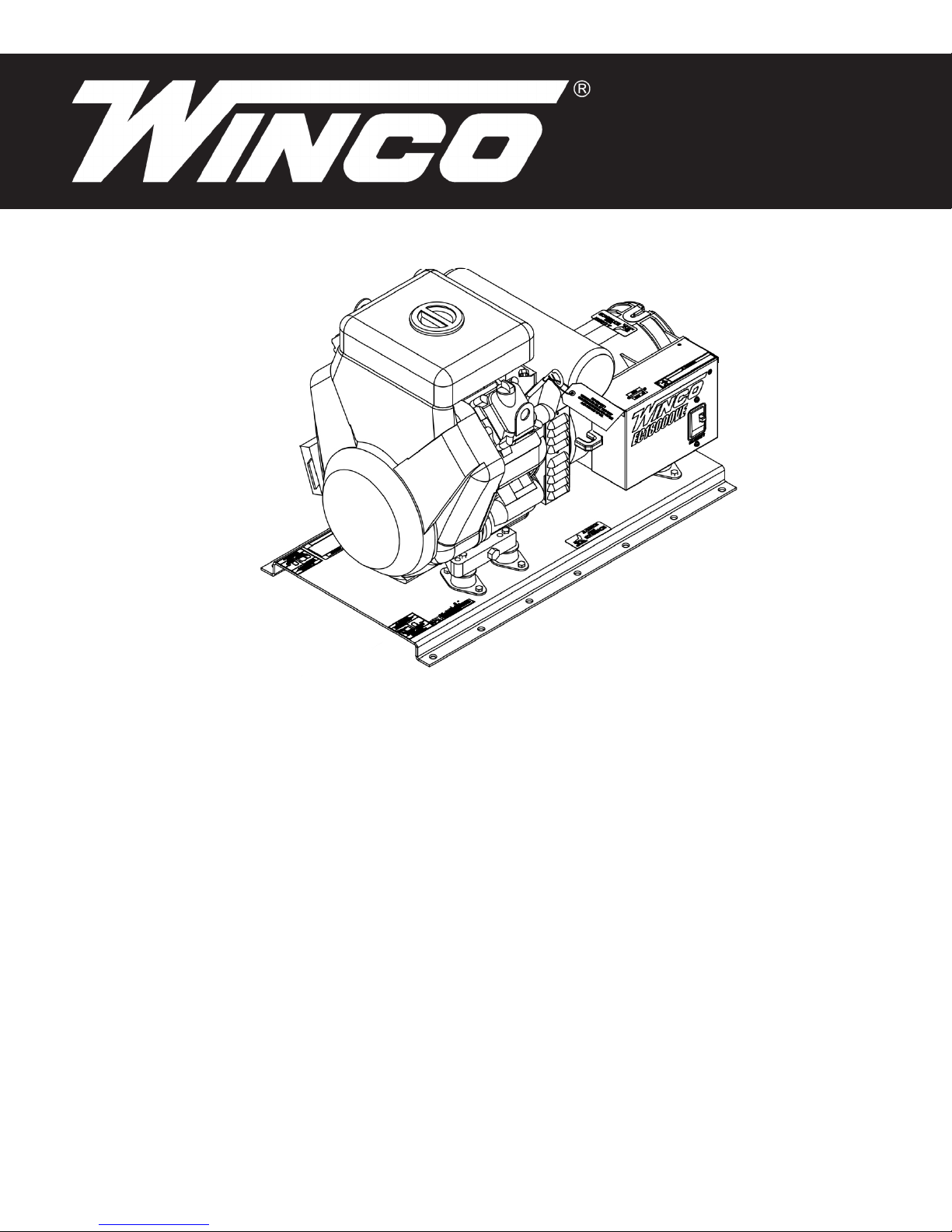
EC18000VE/A
EC22000VE/A
GENERATORS
INSTALLATION AND
OPERATORS
WINCO INC. 225 S. CORDOVA AVE. LE CENTER, MN 56057 507-357-6821
MANUAL
SERVICE DEPT. 507-357-6831
www.wincogen.com
Page 2

TABLE OF CONTENTS
SAVE THESE INSTRUCTIONS 2
TESTING POLICY 2
SPECIFICATIONS 3
SAVE THESE INSTRUCTIONS
This manual contains important instructions that should be followed
during installation and maintenance of the generator. Read and
understand all instructions in the manual before starting and operating
the generator.
SAFETY 4
IMPORTANT SAFETY INSTRUCTIONS
ANSI SAFETY DEFINITIONS
INTRODUCTION 4
INTENDED USES
RESTRICTED USES
UNIT CAPABILITIES 5
GENERATOR CONNECTIONS
STARTING ELECTRIC MOTORS
PREPARING THE UNIT 5
UNPACKING
VENTILATION
GASOLINE
FUEL SUPPLY
LUBRICATION
OIL RECOMMENDATIONS
OIL ALERT SYSTEM
BATTERY INSTALLATION
BATTERY CHARGING
INITIAL START UP 7
BASIC OPERATION
STARTING HINTS
USING THIS MANUAL
Congratulations on your choice of a WINCO generator. You have
selected a high-quality, precision-engineered generator designed and
tested to give you years of satisfactory service.
To get the best performance from your new generator, it is important
that you carefully read and follow the operating instructions in this
manual.
Should you experience a problem please follow the “Troubleshooting
Tables” near the end of this manual. The warranty listed in the manual
describes what you can expect from WINCO should you need service
assistance in the future.
COPY YOUR MODEL AND SERIAL NUMBER HERE
No other WINCO generator has the same serial number as yours.
If you should ever need to contact us on this unit, it will help us to
respond to your needs faster.
MODEL __________________________________________________
SERIAL NUMBER _________________________________________
PURCHASE DATE _________________________________________
CONNECTING THE LOADS 8
APPLYING THE LOADS
GROUNDING
WIRING
ENGINE CARE 9
MAINTENANCE SCHEDULE
CHECKING THE OIL LEVEL
CHANGING THE OIL
GENERATOR CARE 10
EXERCISING THE GENERATOR
GENERATOR MAINTENANCE
CLEANING
DUAL ELEMENT AIR FILTER
SPARK PLUG
CARBON CANISTER
TROUBLESHOOTING 11
OUTLINE DRAWINGS 12
DISTRIBUTION WIRING SCHEMATICS 13
EC22000VE AC WIRING 14
24 MONTH LIMITED WARRANTY 16
DEALER NAME ___________________________________________
DEALER PHONE # ________________________________________
TESTING POLICY
Before any generator is shipped from the factory, it is fully checked
for performance. The generator is loaded to its full capacity, and the
voltage, current, and frequency are carefully checked.
Rated output of generator is based on engineering tests of typical units,
and is subject to, and limited by, the temperature, altitude, fuel, and
other conditions specied by the manufacturer of applicable engines.
60706-231
2
REV B
Page 3

SPECIFICATIONS
EC18000VE
Starting Watts 18,000
Running Watts 15,000
Volts 120/240
Phase 62.5
PF 1.0
Amps 120/240V 125/62.5
CB Size 60 Amp
Hertz 60
ENGINE
Manufacturer Briggs & Stratton
Model Vanguard
543477 2141 G1
Size 895 CC/OHV
Fuel Consumption
Full Load
Half Load
No Load
Starting Electric Key Start
Voltage 12V
2.69 Gal/Hr
1.62 Gal/Hr
0.88 Gal/Hr
EC22000VE
Starting Watts 22,000 22,000 22,000 22,000
Running Watts 19,000 19,000 19,000 19,000
Volts 120/240 120/208 120/240 277/480
Phase Single Three Three Three
PF 1.0 0.8 0.8 0.8
Amps 79 65 57 28
CB Size 80 Amp 60 Amp 60 Amp 30 Amp
Hertz 60 60 60 60
ENGINE
Manufacturer Briggs & Stratton
Model Vanguard
613477 0219 G1
Size 993 CC/OHV
Fuel Consumption
Full Load
Half Load
No Load
Starting Electric Key Start
Voltage 12V
3.28 Gal/Hr
1.88 Gal/Hr
0.95 Gal/Hr
GENERATOR
Generator Manufacturer Mecc Alte
Generator Model Number S20F-230/A
Part Number 16428-002
Rotor Resistance 8.04 Ohms
Stator Resistance 0.0056 Ohms
Auxiliary 1.173 Ohms
Exciter Stator 10.6 Ohms
Exciter Rotor 0.417 Ohms
Capacitor :
31.5µ 425 VAC 300323-112
35µ 425 VAC 300323-212
ENGINE
Spark Plugs 491055
Air Filter 692519
Air Filter Pre-Cleaner 692520
Oil Filter 842921
Fuel Filter 845125
Spark Plug Gap 0.030 in
Intake Valve Clearance 0.004 - 0.006 in
Exhaust Valve Clearance 0.007 - 0.009 in
Oil Capacity 78 - 80 oz (2.4 - 2.5 qts)
GENERATOR
Generator Manufacturer Mecc Alte
Generator Model Number ECP28-2L/2
Part Number 64887-002
Rotor Resistance 5.523 Ohms
Stator Resistance 0.0863 Ohms
Auxiliary 1.173 Ohms
Exciter Stator 10.6 Ohms
Exciter Rotor 0.417 Ohms
ENGINE
Spark Plugs 491055
Air Filter 692519
Air Filter Pre-Cleaner 692520
Oil Filter 842921
Fuel Filter 845125
Spark Plug Gap 0.030 in
Intake Valve Clearance 0.004 - 0.006 in
Exhaust Valve Clearance 0.007 - 0.009 in
Oil Capacity 78 - 80 oz (2.4 - 2.5 qts)
3REV B
60706-231
Page 4

SAFETY
IMPORTANT SAFETY INSTRUCTIONS
SAVE THESE INSTRUCTIONS
This manual contains important information that should be understood
and followed before the installation, operation and maintenance of the
generator. Failure to follow the safety instructions in this manual could
result in serious injury or death. Keep this manual available for future
reference.
ANSI SAFETY DEFINITIONS
DANGER:
DANGER indicates an imminently hazardous situation which, if not
avoided, will result in death or serious injury. This signal word is to be
limited to the most extreme situations.
WARNING:
WARNING indicates a potentially hazardous situation which, if not
avoided, could result in death or serious injury.
CAUTION:
CAUTION indicates a potentially hazardous situation which, if not
avoided, may result in minor or moderate injury. It may be used to alert
against unsafe practices.
NOTE: CAUTION is also used on the unit labels and in this manual to
indicate a situation that could result in serious damage or destruction of
the equipment and possible personal injury.
1. ELECTRIC SHOCK -
The output voltage present in this equipment can cause a fatal electric
shock. This equipment must be operated by a responsible person.
A. Do not allow anyone to operate the generator without proper
instruction.
B. Guard against electric shock.
C. Avoid contact with live terminals or receptacles.
D. Use extreme care if operating this unit in rain or snow.
E. Use only three-prong grounded plugs and extension cords.
F. Be sure the unit is properly grounded to an external ground rod
driven into the earth.
2. FIRE HAZARD -
A. Keep a re extinguisher nearby and know its proper use. Fire
extinguishers rated ABC by NFPA are appropriate.
3. NOISE HAZARD -
Excessive noise is not only tiring, but continual exposure can lead to
loss of hearing.
A. Use hearing protection when working around this
equipment for long periods of time.
B. Keep your neighbors in mind when permanently installing this
equipment.
60706-231
4. CLEANLINESS -
Keep the generator and surrounding area clean.
A. Remove all grease, ice, snow or materials that create slippery
conditions around the unit.
B. Remove any rags or other materials that could create a
potential re hazard.
C. Carefully clean up any gas or oil spills before starting the unit.
5.SERVICING EQUIPMENT -
All service, including the installation or replacement of service parts,
should be performed only by a qualied technician.
A. Use only factory approved repair parts.
B. Do not work on this equipment fatigued.
C. Use extreme caution when working on electrical components.
High output voltages from this equipment can cause serious
injury or death.
D. Installing a generator is not a “do-it-yourself” project. Consult
a qualied, licensed electrician or contractor. The installation
must comply with all national, state, and local codes.
INTRODUCTION
INTENDED USES
The EC1800VE engine generator set has been designed primarily for
heavy duty commercial use. Both 120 volt and 240 volt receptacles are
provided in the control panel to plug in your loads. The EC22000VE
is hard-wire connectible only. These units are dual wound generators,
therefore the 120 volt loads must be equally split with 1/2 of the rated
capacity available on each of the two 120 volt circuits.
These units require large quantities of fresh air for cooling the engine
and generator. For safety, long life and adequate performance, these
units should never be run in small compartments without positive fresh
air ow.
RESTRICTED USES
DO NOT install and operate this generator in a small compartment.,
i.e. generator compartments of vehicles, motor homes or travel
trailers. These compartments will not allow enough free ow of fresh
air to reach the engine generator set for cooling and will cause the
unit to overheat, damaging both the engine and generator. Small
compartments will also develop hot spots where there is very little air
ow and may cause a re.
PLEASE NOTE There are 3rd party companies making enclosures for
generators that have been properly engineered. The use of these 3rd
party enclosures is acceptable as long as they have been certied and
meet current code.
DO NOT attempt to operate at 50 cycles. These units are designed and
governed to operate at 60 cycles only.
4
REV B
Page 5
UNIT CAPABILITIES
low speeds, the electric motor starting winding will burn out in a short
time. The generator winding might also be damaged.
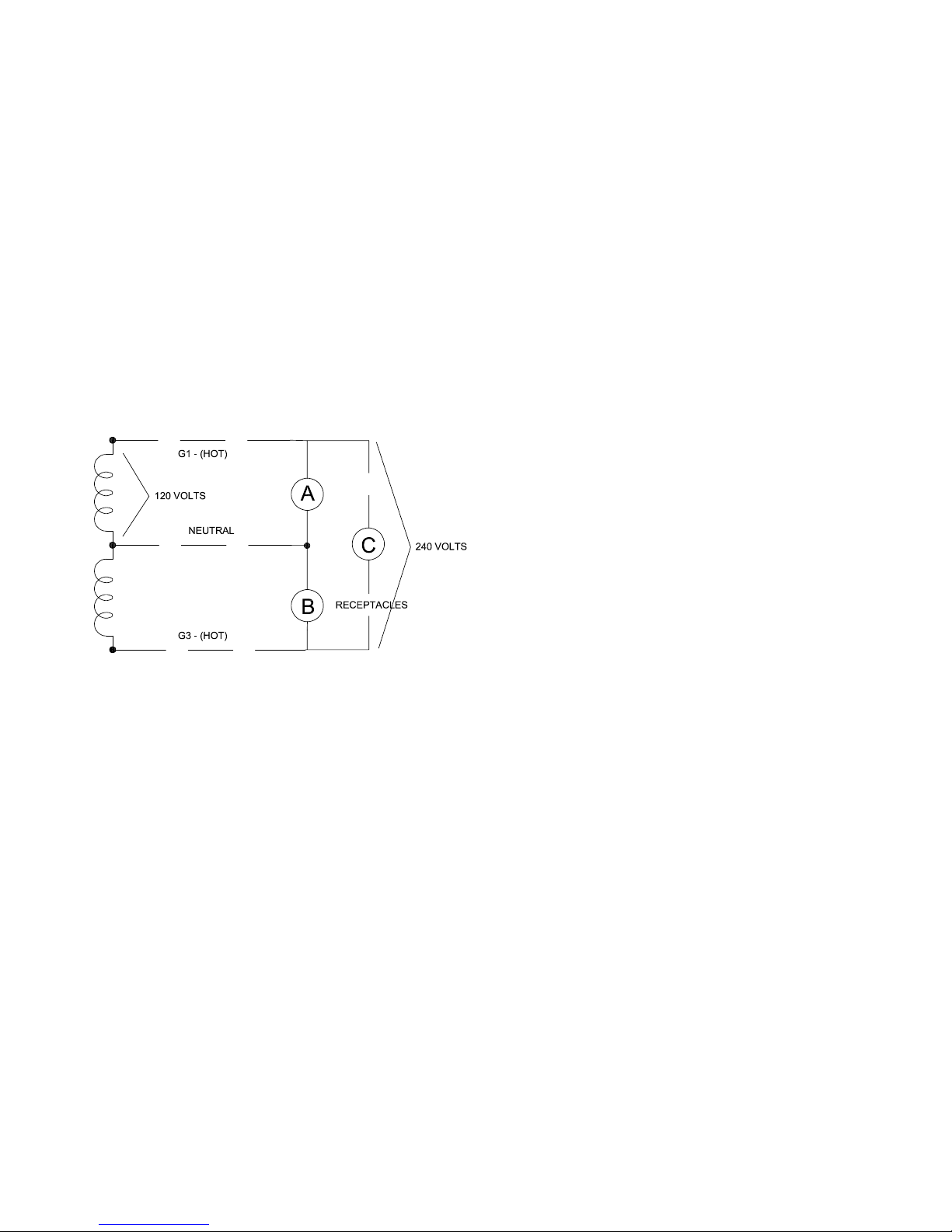
GENERATOR CONNECTIONS
The diagram below represents this 15,000 watt (rated output)
generator. A & B represent the 120 volt output legs of this generator.
Up to 7500 watts at 120 volts (45 Amps) can be drawn from the
receptacles attached to either A or B output legs. This generator is
capable of producing 62.5 Amps of 240 volt current at C. Check the
appliance or tool nameplates for the current and voltage to insure
compatibility. Remember that power taken from C reduces the power
available at equally both A and B and vice versa.
Check the appliance or tool nameplates for the current and voltage
to ensure compatibility. Remember tha power utilized from C reduces
the power available from both A and B and vice versa. The EC22000
utilizes the same format with A and B being 9500 Watts and C being
19,000 Watts.
CAUTION: EQUIPMENT DAMAGE
Running the generator set under these conditions may result in
damage to the generator stator as well as the motor winding.
The heavy surge of current required for starting motors is required for
only an instant. The generator will not be damaged if it can bring the
motor up to speed in a few seconds of time. If difculty is experienced
in starting motors, turn all other electrical loads off and if possible
reduce the load on the electric motor.
PREPARING THE UNIT
UNPACKING
CAUTION: EQUIPMENT DAMAGE
THIS UNIT HAS BEEN SHIPPED WITHOUT OIL. Failure to maintain
the engine oil at the proper level will result in serious engine damage.
When you unpack your engine-generator set be sure to remove all the
information sheets and manuals from the carton.
1. As you receive your unit, it is critical to check it for any damage. If
any damage is noted, it is always easiest to refuse the shipment and
let WINCO take care of the freight claim. If you sign for the unit, the
transfer of the ownership requires that you le the freight claim
STARTING ELECTRIC MOTORS
Electric motors require much more current (amps) to start them than to
run them. Some motors, particularly low cost split-phase motors, are
very hard to start and require 5 to 7 times as much starting current as
running current. Capacitor motors are easier to start and usually require
2 to 4 times as much starting current as running current. Repulsion
Induction motors are the easiest to start and require only 1 1/2 to 2 1/2
times as much starting as running current.
Most fractional horsepower motors take about the same amount
of current to run them whether they are Repulsion Induction (RI),
Capacitor (Cap), or Split-Phase (SP) type.
If the electric motor is connected to a hard starting load such as an air
compressor, it will require more starting current. If it is connected to a
light load, or no load such as a power saw, it will require less starting
current. The exact requirement will also vary with the brand or design
of the motor.
Self-exciting generators respond to severe overloading differently than
utility power. When overloaded, the engine is not able to supply enough
power to bring the electric motor up to operating speed. The generator
responds with high initial starting current, but the engine speed drops
sharply. The overload may stall the engine. If allowed to operate at very
2. Before proceeding with the preparations of your new generator
for operation, take a couple of minutes to ensure the unit you have
received is the correct model and review the specication pages in this
manual to ensure that this unit meets your job requirements.
VENTILATION
These engine generator sets use large amounts of fresh air for cooling.
When designing plans for your installation, special attention must be
paid to the ow of hot air from both the engine and the generator.
Both the engine and the generator must be supplied with a constant
ow of fresh air from the outside to ensure they don’t overheat. Some
provision must be made to remove the hot air out the enclosure.
Ambient temperature around the unit should not exceed 122°F.
Engine or generator failures resulting from inadequate ventilation
are considered abuse and not covered by the generator or engine
manufacturer’s warranty.
The engine exhaust from this engine must be vented to the outside.
When venting hot exhaust through any type of ammable wall be sure
to use exhaust thimbles to prevent res.
WARNING:
Failure to properly vent out the exhaust out of an enclosure can and will
kill you. Carbon monoxide is both invisible and orderless, it can build up
very rapidly in any enclosure not properly vented.
5REV B
60706-231
Page 6

GASOLINE
LUBRICATION
When using gasoline, always use fresh, clean, unleaded fuel. The
engine is certied to operate on unleaded gasoline with a minimum
octane rating of 87 or higher. Gasoline containing no more the 10%
ethanol is acceptable.
CAUTION: EQUIPMENT DAMAGE
Do not use unapproved gasolines, such as E15 or E85. Do not mix
oil in the gasoline. Use of unapproved fuels will damage the engine
compenents and void the engine warranty.
Use of fuels with content of ethanol greater than shown above may
cause starting and/or performance problems. Always ensure that the
fuel is clean and free of all impurities.
WARNING: FIRE DANGER
Gasoline and its fumes are VERY explosive when proper precautions
are not taken.
Never use gasoline that has been stored for an extended period of
time as the fuel will lose its volatile properties and you will be left with
varnish residue. The varnish like substance will clog the carburetor and
will not burn properly.
The use of fuel additives, such as Sta-Bil, or an equivalent will minimize
the formation of fuel gum deposits. If a unit has been out of operation
for an extended period of time, it is best to drain old fuel from the
engine and replace with fresh fuel before attempting to start.
FUEL SUPPLY
The EC units provide exibility in where they get gasoline from.
Whether you are using our optional fuel tank, or supplying your own,
there are some important factors to consider. The fuel pump on the unit
is only capable of about 30” of lift in ideal circumstances. Tank size,
tank location, hose size, hose routing, and hot spots all play a role in
a successful fuel tank installation. Preferred fuel installations use 1/4”
hose that run straight to the engine with no drops or twists from an
adequately (15 gallons) sized fuel tank.
Before starting the engine, ll the crankcase to the proper level with
a good quality oil. The recommended grade oil and quantity of oil
required is listed in the engine operator’s manual and under the service
tab in this manual. This unit was shipped with most of the oil removed.
The engine normally holds 78 - 80 oz (2.4 - 2.5 qts) of oil. Since there
is some trapped in the engine, when lling the crankcase the rst time,
use the dipstick to ensure that you do not over ll the crankcase. The
full oil level mark on the dipstick is depicted in the following image.
Oil is added to the engine by removing the oil cap and adding oil at
this point. After lling the crankcase to the proper level, be sure you
properly tighten the oil ll cap.
NOTE: This engine generator must be on a level surface before you
check or add oil to the system.
The necessity of using the correct oil and keeping the crankcase full
cannot be overemphasized. Engine failures resulting from inadequate
or improper lubricant are considered abuse and not covered by the
generator or engine manufacturer’s warranty.
OIL RECOMMENDATIONS
Outdoor temperatures determine the proper oil viscosity for the
engines. Use the chart to select the best viscosity for the outdoor
temperature range expected.
1. The fuel lift from the bottom of the tank to the fuel outlet on the
generator must not exceed 30”. If a greater lift is required, it
may be necessary to provide an additional electric fuel pump to
ensure the engine get a sufcient ow of fuel.
2. EPA regulations require the installation of a carbon canister on the
tank vent line. This is to prevent the escape of fuel vapors in to
the atmosphere.
3. You need to have a primer bulb in the fuel line to prime the fuel
from the tank to the fuel pump. The vacuum fuel pump on the
engine will not draw the fuel up from the tank until the line has
been properly primed.
4. In all cases the minimum fuel line size must be 1/4” or larger line.
And the fuel line must be certied for use with unleaded gasoline.
60706-231
OIL ALERT SYSTEM
This generator is equipped standard with the Briggs & Stratton low oil
pressure shutdown system. The low oil shutdown system is designed
6
REV B
Page 7

to prevent severe damage caused by an insufcient amount of oil in
the crankcase. However, if the unit is repeatedly allowed to shutdown
on low oil pressure, progressive damage will be done to the engine,
shortening the engine’s life. The engine switch will remain in the “ON”
position when the unit is shutdown by the low oil pressure system.
CAUTION: EQUIPMENT DAMAGE
Allowing the engine to shutdown repeatedly on low oil level may cause
excessive wear which can be cumulative.
BATTERY INSTALLATION
INITIAL START UP
The throttle control on these generators is preset and locked to operate
at 3600 RPM (nominal) with no load speed set at 3690 RPM. Only
a trained service technician should be allowed to adjust this speed
setting.
NOTICE: ENGINE START LOCKOUT
This unit will not start if it is low on oil. The lubricating oil level must be
at the full mark before the engine will start and run.
You will need to connect this unit to a battery to operate it. Cables
have not been provided as length are going to vary depending on
your installation. These engines are all negative ground. The positive
battery cable must be connected to the open large terminal on the
start solenoid (This terminal may have a small 16 GA. wire on it for
the charging circuit). The negative cable should be attached to a good
ground on the engine. This is usually one of the starter mounting studs.
A twelve volt battery, rated at 300 CCA or larger is recommended for
this electric start generator set. Follow the battery manufacturer’s
recommendations for servicing and charging prior to use.
A 12 Volt battery, BCI group 26 rated at 500 CCA or larger is
recommended for this electric start engine-generator set. Follow the
battery manufacturers recommendations for servicing and charging
prior to use. Connect the battery to the electric start system using the
cables provided.
CAUTION: EQUIPMENT DAMAGE
These electric start engines are NEGATIVE GROUND. Use extreme
caution when connecting the battery. Connect the NEGATIVE battery
terminal to GROUND.
For your safety, always connect the positive battery cable to the “bat+”
terminal rst. Then connect the negative battery cable to the “Bat-”
terminal. Make sure all connections are clean an tight. Reverse the
sequence when disconnecting, disconnect the negative cable rst.
These engines produce enough direct current to keep the battery
charged under normal operating conditions, but were not intended to
be used as a battery charger.
WARNING: PERSONAL INJURY
Lead acid batteries produce explosive hydrogen gas when charging.
Keep sparks, ames, and burning cigarettes away from the battery.
Ventilate the area when charging or using the battery in an enclosed
space. Lead acid batteries contain sulfuric acid, which causes severe
burns. If acid contacts eyes, skin, or clothing, ush well with water. For
contact with the eyes, get immediate medical attention.
BATTERY CHARGING
Units have a small ywheel charger built into the engine ywheel
assembly for recharging the starting battery. This ywheel charger
generates a small AC current that passes through a diode assembly
to produce DC charging current of about 1 to 3 Amps. This circuit is
not designed to be used as a battery charging circuit to recharge dead
batteries.
BASIC OPERATION
CAUTION: EQUIPMENT DAMAGE:
Always start the unit with the circuit breaker open, never start with the
load applied. Always keep the battery charged, especially during cold
weather operation.
1. Turn on the fuel supply
2. Using the primer bulb, make sure the fuel is pumped up the the
fuel pump on the engine.
3. Move the choke to the full “ON” position for starting. A warm
engine will require less choking than a cold one.
4. Turn the key to the start postion. Thart starter life is improved
by using shorter start cycles. Do not operate the starter more than
15 seconds during each minute. Repeat as necessary.
5. When the engine starts, release the key and open the choke
gradually.
6. The enigne should promptly come up to operating speed.
CAUTION: EQUIPMENT DAMAGE
Never permit the choke to remain on after the engine has run for a
short time. It is not necessary to choke the engine when it is warm.
Avoid over-choking.
STARTING HINTS
1. COLD WEATHER
A. Use the proper oil for the temperature expected.
B. Use fresh winter grade fuel. Winter grade gasoline is blended to
improve starting. Do not use summer grade gasoline.
2. HOT WEATHER
A. Use the proper oil for the temperature expected.
B. Use only summer blended gasoline. Using gasoline left over from
winter may cause the unit to vapor lock.
7REV B
60706-231
Page 8

STOPPING AND STORING
1. Move the key to the “OFF” position.
2. Turn off the fuel supply valve.
3. Before extended storage (over 30 days) certain precautions
must be taken to ensure the fuel doesn’t deteriorate and clog the
fuel system.
NOTE: The use of a fuel additive, such as Sta-Bil or equivalent will
minimize the formation of gum deposits during storage. The additive
may be added to gasoline in the engines fuel tank or to gasoline in a
storage container.
A. Add the fuel stabilizer to the fuel in the tank and run for 2 minutes
to circulate the stabilizer throughout the fuel system.
B. Remove the remaining fuel from the fuel tank, it must be drained
into an approved container.
C. Start the engine and allow it to run until all the fuel in the
carburetor and the fuel lines has been used up and the engine
stops.
NOTE: Running the engine to use up the fuel in the lines and
carburetor will still leave a small amount of fuel in carburetor. It is best
extended storage to treat the fuel before draining.
D. While the engine is warm, drain the oil and rell with fresh oil.
E. Remove the spark plug, pour approximately 1/2 oz. (15cc) of
engine oil into the cyclinder and crank slowly to distribute the oil.
Replace the spark plug.
E. Clean dirt and chaff from cylinder, cylinder head ns, blower
housing, screen, and mufer areas.
F. Store in a clean and dry area.
LOAD vs. OUTPUT
Generator
Load
None 3690 61.5 125V
Half 3600 60.0 120V
Full 3510 58.5 115V
The speed of the engine was carefully adjusted at the factory so that
the generator produces the proper voltage and frequency. For normal
usage, the speed setting should not be charged. If the generator is
being run continuously on a very light load, it is often advisable to lower
the operating speed slightly.
CAUTION: EQUIPMENT DAMAGE
SPEED ADJUSTMENTS SHOULD ONLY BE MADE BY A QUALIFIED
SERVICE TECH. Whenever making any speed adjustments, check the
unit with a voltmeter and a frequency meter or a tachometer and be
sure the voltage and speed are correct.
Lower voltage may damage both the generator and any load connected
to it. Running the engine at excessively high speeds results in high
voltage, which may signicantly shorten the life of appliances being
used.
Output voltage should be checked periodically to ensure continued
proper operation of the generating plant and appliances. If the
generator is not equipped with a voltmeter, it can be checked with a
portable meter. Frequency can be checked by using an electric clock
with a sweep second hand. Timed against a wrist watch or a stop
watch, the clock should be correct within +/- 2 seconds per minute.
Speed
(RPM)
Frequency
(Hz)
Voltage
OPERATING SPEED
The engine-generator must be run at the correct speed in order to
produce the proper electrical voltage and frequency.
CAUTION: EQUIPMENT DAMAGE
The output voltage should be checked to ensure the generator is
working properly prior to connecting a load to the generator. Failure to
do so could result in damage to equipment plugged into the unit and
possible injury to the individual.
All engines have a tendency to slow down when a load is applied.
When the electrical load is connected to the generator, the engine is
more heavily loaded, and as a result, the speed drops slightly. This
slight decrease in speed, together with the voltage drop within the
generator itself, results in a slightly lower voltage when the generator
is loaded to its full capacity than when running no load. The slight
variation in speed also affects the frequency of the output current.
This frequency variation has no appreciable effect in the operation of
motors, lights, and most appliances. However, electronic equipment
and clocks will be affected if correct RPM is not maintained. See Load
vs. Output chart.
Although individual units and models vary slightly, the normal voltage
and frequency of the engine-generator described in this manual are
approximately as follows, under varying loads:
CONNECTING THE LOADS
Failure to properly limit and balance the load applied to the generator
will cause the generator to produce low voltage and may damage
the engine generator set. It may also cause severe damage to the
loads connected to the generator at the time. Improper loading of the
generator set constitutes abuse and will not be covered by warranty.
A 60 Amp receptacle (NEMA 14-60) has been provided to allow
the connection of loads to the generator on the EC18000VE. This
receptacle is a 4-wire, full load receptacle protected by a 60 Amp
breaker mounted in the control box on top of the generator.
With the EC22000VE, the load wiring must be wired directly in the
80 Amp breaker mounted in the control box on thop of the generator.
When wiring directly to the circuit breaker in the box, be sure to
connect a neutral wire and ground wire to the appropriate locations in
the control box.
Your individual loads must be protected by individual circuit breakers
mounted in some type of distribution panel. This location will also be
where you will install your neutral to ground bond. You must wire four
separate wires from the generator (2-hot, 1- neutral, and 1-ground) to
the distribution panel.
60706-231
8
REV B
Page 9

APPLYING THE LOADS
Allow the engine to warm up for two or three minutes before applying
any load. This will allow the engine to reach normal operating
temperature and oil to circulate throughout the engine. A shot warm-up
time will permit the engine to work more efciently when the load is
applied and will reduce the wear in the engine, extending its life.
Receptacles have been provided to allow loads to be connected to the
generator. The loads should be added one at a time. If a large motor
is being started: or multiple motors are being started, they should be
started individually and the largest should be started rst.
CAUTION: EQUIPMENT OVERLOAD
Keep the generator load within in the generator and receptacle
nameplate rating. Overloading may cause damage to the generator
and/or the loads.
Most electric tools and appliances will have the voltage and amperage
requirements on their individual nameplates. When in doubt, consult
the manufacturer or a local electrician. The nameplate amperage rating
for electric motors can be misleading. See “Starting Electric Motors” in
the Unit Capabilities.
These engine-generator sets are inherently self regulating based on
engine speed. The engine governor will automatically adjust itself to
the load. No harm to the generator will result if it is operated with no
load connected. The generator is a limited source of electrical power,
therefore, pay special attention to the receptacle and generator ratings.
ENGINE CARE
MAINTENANCE SCHEDULE
If major engine service or repair is required, contact an authorized
engine service center. The manufacturer of these engines has
established an excellent world-wide engine service organization.
Engine service is very likely available from a nearby authorized dealer
or distributor. See following table.
GROUNDING
All units must be grounded. Different installations will require different
grounding requirements. Depending on your installation, ensure that
the ground meets your governing codes.
WIRING
For your safety, all wiring must be done by a qualied electrician
and conform to the National Electric Code and comply with all state
and local codes and regulations. Check with local authorities before
proceeding.
CAUTION: EQUIPMENT DAMAGE
Failure to properly limit and balance the load a[[lied to the generator
will cause the generator to produce low voltage and may damage
the engine generator set. It may also cause severe damage to the
loads connected to the generator at that time. Improper loading of the
generator set constitutes abuse and will not be covered by warranty.
CHECKING THE OIL LEVEL
The oil level must always be checked before the engine is started.
Refer to page 5 of this manual for instructions on checking the oil level.
Take care to remove any dirt or debris from around the oil plug before
removing. Be sure the oil level is maintained.
CHANGING THE OIL
Refer to the Maintenance Schedule Chart for required oil change
intervals.
A. Start the engine and warm it up, stop the engine and remove the
spark plug wire to prevent it from accidentally being started.
B. This engine has an oil drain valve for your convenience. Attach a
neoprene hose and drain the oil into an approved container.
Neoprene hose, 1/2” I.D.
Cut to length
9REV B
60706-231
Page 10

C. Remove the oil lter and dispose of it properly.
D. Before you install the new oil lter, clean the lter mounting base
and coat the seal of the new oil lter will clean engine oil.
E. Install the oil lter by hand until the gasket contacts the oil lter
adapter, then tighten the oil lter 1/2 to 3/4 turns.
F. Replace oil drain bolt making sure the sealing washer is in place.
G. Remover the oil lter plug and rell with new oil. Make sure to use
the proper grade oil based on your operating temperature.
GENERATOR CARE
Proper care and maintenance of the generator is necessary to ensure a
long trouble free life.
EXERCISING THE GENERATOR
NOTE: This engine requires 78 to 80 ounces (2.4 to 2.5 quarts) of oil if
it is completely drained. Use caution when relling the engine as some
residual oil may have remained in the engine. Always use the dipstick
when lling the engine with oil to prevent overlling.
H. Replace lter plug.
I. Start the engine and warm it up.
J . After warming up the engine, recheck the oil level and rell as
necessary to bring it to the proper level.
DUAL ELEMENT AIR FILTER
Clean and/or replace the foam pre-cleaner and the air lter annually or
every 100 hours. Service more often under dusty conditions.
WARNING: EQUIPMENT DAMAGE
Never start or run the engine with the air lter removed.
A. Loosen snaps (A) and
remove cover (B).
B. Remove the nut (D) and the
retainer (E).
C. Remove the air lter (F).
D. Remove the pre-cleaner (G)
from the air lter.
E. To loosen debris, gently tap the
air lter on a hard surface. If the
air lter is excessively dirty
replace with a new lter.
You can use pressurized air
(not to exceed 30 psi)
to clean the lter. Always blow the compressed air from inside to
the outside.
F. Wash the pre-cleaner in liquid detergent and water. Then allow it
to thoroughly air dry. DO NOT oil the pre-cleaner.
G. Install the pre-cleaner to the air lter.
H. Install the air lter and secure the retainer and nut.
I. Install and secure the cover.
E
F
B
A
D
G
SPARK PLUG
Replace annually or every 300 hours of operation. Always replace with
the same spark plug that came in the engine and check gap before
installing. Spark plug gap is 0.030”. Poor spark will also occur if spark
plug wire does not t rmly on spark plug. If this happens, reform the
terminal to t rmly on spark plug tip.
The generator should be operated every three to four weeks. It should
be operated for a period of time sufcient to warm the unit up and to
dry out any moisture that has accumulated in the windings. If left, this
moisture can cause corrosion in the winding. Frequent operation of the
engine-generator set will also ensure that the set is operating properly
should it be needed in an emergency.
GENERATOR MAINTENANCE
Any major generator service, including the installation or replacement
of parts, should be performed only by a qualied electrical service
technician. USE ONLY FACTORY APPROVED REPAIR PARTS.
A. Bearing - The bearing used in these generators is a heavy duty,
double sealed ball bearing. They require no maintenance or
lubrication.
B. Receptacles - Quality receptacles have been utilized. If a
receptacle should become cracked or otherwise damaged,
replace it. Using damaged or cracked receptacles can be both
dangerous to the operator and destructive to the equipment.
CLEANING
Remove dirt and debris with a cloth or brush. DO NOT use high
pressure spray to clean either the engine or the generator. The high
pressure spray could contaminate the fuel system and the generator
components.
1. Keep the air inlet screen on both the engine and generator free of
any dirt or debris to ensure proper cooling. At least yearly, remove
the blower housing on the engine and clean the chaff and dirt out of
the engine cooling ns and y wheel. Clean more often if necessary.
Failure to keep these areas clean may cause overheating and
permanent damage to the unit.
2. Periodically clean mufer area to remove all grass, dirt, and
combustible debris to prevent a re.
3. On engine mufers equipped with spark arresters, the spark arrester
must be removed every 50 hours for cleaning and inspection. Replace
if damaged.
CARBON CANISTER
Designed to collect, store, and dispose of fuel vapors created in the
fuel tank/fuel system. The canister should last the life of the unit as long
as it stays dry.
60706-231
10
REV B
Page 11

TROUBLESHOOTING
Problem Possible Causes
Won’t start Low oil level
Fouled spark plug
Out of fuel
Start switch in OFF position
Fuel Valve turned off
Plugged fuel lter
Blown fuse in key switch
Voltage too low Engine speed is too low
Generator overloaded
Defective stator
Defective rotor (eld)
Defective capacitor (EC18000VE)
Circuit breaker trips Defective load
Defective receptacle
Excessive load
Voltage too high Engine speed is too high
Generator overheating Overloaded
Insufcient ventilation
No output voltage Short in load (disconnect)
Tripped or defective circuit breaker
Broken or loose wire
Defective receptacle
No residual magnetism (in generator)
Defective stator
Defective rotor (eld)
Shorted capacitor
Shorted diodes on rotor
GFCI receptacle tripped
11REV B
60706-231
Page 12

38.000
25.042
21 3
21.660
5 986
ITEM NO.
PartNo
DESCRIPTION
QTY.
REVISIONS
REV
IRN
DESCRIPTION
DATE
BY
APP'D
A
ORIGINAL
MVW
B
REDESIGNED RECEPTACLE BOX
6/20/12
PJY
MVW
C
3630
60706-231 ADDED
3/24/2015
KS
DRC
D
5271
REPLACED 473-000 WITH 467-000 ADDED 526-000
5/17/2016
RJD
ZJF
19022-000
PJY
4/27/2012
21.161
4/26/2012
19018-000
PJY
REVISIONS
REV IRN DESCRIPTION DATE BY APP'D
A ORIGINAL
B CHANGED DECAL SET FROM 15715-057 TO 19018-011 4/26/12 PJY CLR
C ADDED SHIPPING CARTON TO BILL 4/27/12 PJY CLR
D REMOVED FUEL KIT FROM BILL 5/3/12 PJY CLR
E 3706 60706-231 ADDED 4/7/2015 KS DRC
2
18.641
34.000
32.685
24.059
1
OUTLINE DRAWINGS
EC18000VE
60706-231
EC22000VE
REV B
12
Page 13

DISTRIBUTION WIRING SCHEMATICS
EC18000VE
EC22000VE
120/240 SINGLE PHASE 120/208 & 120/240 THREE PHASE
277/480 THREE PHASE
13REV B
60706-231
Page 14

Page 14
0210-10 REV B
60706-197
THREE PHASE AC WIRING
HIGH AND LOW WYE
THREE PHASE-LOW WYE
120/208 VOLTS
THREE PHASE-HIGH WYE
277/480 VOLTS
Page 14
60706-197
THREE PHASE-LOW WYE
120/208 VOLTS
EC22000VE AC WIRING
3-PHASE
277/430 HIGH WYE
3-PHASE
120/208 LOW WYE
60706-231
14
REV B
Page 15

THREE PHASE AC WIRING - DELTA
SINGLE PHASE AC WIRING
SINGLE PHASE
120/240 VOLTS
THREE PHASE -DELTA
120/240 VOLTS
THREE PHASE -DELTA
120/240 VOLTS
1-PHASE
120/240
3-PHASE
120/240 DELTA
15REV B
60706-231
Page 16

24 MONTH LIMITED WARRANTY
WINCO, Incorporated warrants to the original purchaser for 24 months, that goods manufactured or supplied by it
will be free from defects in workmanship and material, provided such goods are installed, operated and maintained in
accordance with WINCO written instructions.
WINCO’s sole liability, and Purchaser’s sole remedy for a failure under this warranty, shall be limited to the repair of the
product. At WINCO’s option, material found to be defective in material or workmanship under normal use and service
will be repaired or replaced. For warranty service, return the product within 24 months from the date of purchase,
transportation charges prepaid, to your nearest WINCO Authorized Service Center or to WINCO, Inc. at Le Center
Minnesota.
THERE IS NO OTHER EXPRESS WARRANTY.
To the extent permitted by law, any and all warranties, including those of merchantability and tness for a particular
purpose, are limited to 24 months from date of purchase. In no event is WINCO liable for incidental or consequential
damages.
Note: Some states do not allow limitation on the duration of implied warranty and some states do not allow the exclusion
or limitation of incidental or consequential damages, so the above limitations may not apply in every instance. This
warranty gives you specic legal rights which may vary from state to state.
WINCO reserves the right to change or improve its products without incurring any obligations to make such changes or
improvement on products purchased previously.
EXCLUSIONS:
WINCO does not warrant Engines. Engines are covered exclusively by the warranties of their respective manufacturers,
see enclosed warranties.
WINCO does not warrant Component Parts that are warranted by their respective manufacturers.
WINCO does not warrant modications or alterations which were not made by WINCO, Inc.
WINCO does not warrant products which have been subjected to misuse and/or negligence or have been involved in an
accident.
This warranty does not include travel time, mileage, or labor for removal or re-installation of WINCO product from its
application.
WINCO INC. • 225 S. CORDOVA AVE. • LE CENTER, MN 56057 • 507-357-6821
60706-231
16
REV B
 Loading...