

Page 1
2
INSTALLATION INSTRUCTIONS
FUEL TANK KIT
EC18000VE & EC22000VE
3
1
4
5
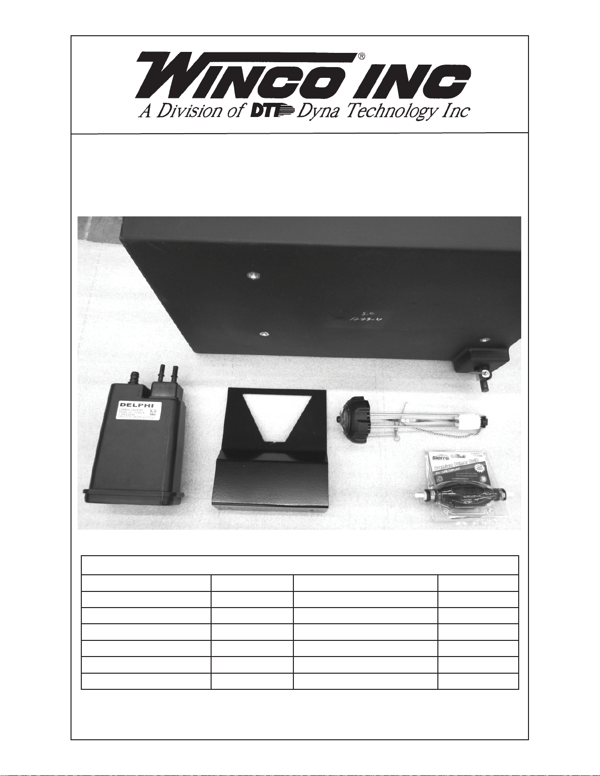
COMPONENT LIST
REF. # PART # DESCRIPTION QTY.
1 81900-001 Carbon Canister Bracket 1
2 80900-000 Carbon Canister 1
3 16316-001 15 Gallon Fuel Tank 1
4 62397-001 Fuel Cap with Gauge 1
5 62391-000 Primer Bulb 1
NOT SHOWN 19018-411 Bag of Parts 1
CUSTOMER SUPPLIED 1/4” AND 5/16” FUEL HOSE CONNECTED TO THE
FUEL TANK IS NOT PROVIDED IN THIS KIT.
112127-00 19018-400I
Page 2
STEP 1
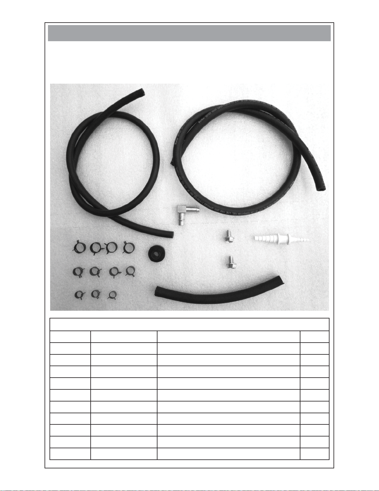
Account for all components, hardware and fasteners.
•
FASTENERS & MISC. COMPONENTS
(not shown in actual size)
7
6
11
14
8
12
13
9
15
10
HARDWARE & FASTENER LIST
REF # PART # DESCRIPTION QTY
6 40078-000 1/4” Fuel Hose 36”
7 40077-000 3/16” Fuel Hose 34”
8 62999-004 Black Hose Clamp .69” OD 4
9 62999-001 Red Hose Clamp .5”OD 4
10 62999-005 Green Hose Clamp .41” OD 3
11 98435-001 Hose Fitting Elbow 1
12 62409-000 Bushing 1
13 62173-001 5/16” Self-Tapping Screw 2
14 98590-003 1/8” - 5/16” X 1/4” - 7/16” Hose Reducer 1
15 40079-000 5/16” Fuel Hose 8”
212127-00 19018-400I
Page 3

STEP 2
Attach the carbon canister bracket (ref. 1) using the two self-tapping screws
•
(ref.13)
Slide the carbon canister (ref. 2) up into the carbon canister bracket (ref.1) and
•
then slide it down until it is locked in place.
STEP 3
Mount fuel tank (ref. 3) in a suitable location to ensure proper fl ow of fuel. The
•
fuel tank must be mounted to a bracket to allow access to the shut-off valve. Bolt
holes are provided on the bottom of the fuel tank for mounting to a stable structure. Use 3/8-16 X ? bolts. The length will vary depending on the mounting structure. NOTE: When mounting the fuel tank below the level of the engine an additional fuel pump may be required for a lift of 3 feet or more from the bottom of the
fuel tank to the fuel pump on the engine. Hose lengths may have to be adjusted
for your application.
Install bushing (ref. 12) and hose fi tting elbow (ref. 11) into the top of the fuel tank.
•
Install fuel cap with gauge (ref.4) on top of the fuel tank.
•
312127-00 19018-400I
Page 4

STEP 4
Route customer supplied 1/4” fuel line from fuel tank to engine and attach the fuel
•
line to the primer bulb (ref. 5) with red hose clamps. Attach 1/4” fuel hose (ref. 6)
to the other side of the primer bulb (ref. 5) with red hose clamp (ref. 9) and route to
the fuel fi lter (ref. A) on the engine. See step 5 below.
Attach 1/4” fuel hose (ref. 6) to the fuel fi lter (ref. A) on the engine using red hose
•
clamp (ref. 9).
STEP 5
Below is your fuel supply connection point on the engine. Fuel fi lter (ref. A) is
•
where you connect the fuel line (ref. 6) from Step 4.
NOTE: Each installation may vary. Your fuel line lengths may vary depending on
•
your installation requirements.
DANGER: Do not allow fuel lines to lay directly on “HOT” surfaces! This
•
may cause a fi re.
A
412127-00 19018-400I
Page 5

STEP 6
Locate the small plastic bag that came with the Briggs & Stratton engine operators
•
manual. You will use the plastic connector (ref. B) in step 6. You can discard the
other part as it is not needed in this application.
B
STEP 7
Slide black hose clamps (ref. 8) onto 5/16” fuel hose (ref. 15) by compressing
•
them with a pliers. Push hose (ref. 8) onto carbon canister nipple marked PURGE
and move the clamp into position at the end of the hose.
Twist and push hose reducer (ref. 14) onto hose (ref. 15) and move clamp into
•
position at the end of the hose. NOTE: You can use a small amount of vegetable
oil on the hoses to ease in their connection.
Repeat process for 3/16” hose (ref. 7). This will connect to the engine hose in step
•
8.
B
10
14
10
8
7
15
8
2
512127-00 19018-400I
Page 6

STEP 8
•
Locate the hose (ref. C) on the left side of the engine that has a plastic ball inserted in the end of it. Use a small screw driver to remove the ball.
•
Slide green hose clamp (ref. 10) over hose (ref. C) using a pliers.
•
Route hose assembly (built in step 7) from the carbon canister (ref. 2) to this hose
and insert the connector (ref. B) into hose (ref. C).
Slide green hose clamp down to the end of the hose clamping it to the connector
•
(ref. B).
C
STEP 9
•
Attach customer supplied 5/16” fuel hose to hose fi tting elbow (ref. 11) on top of
the fuel tank. See step 4 for illustration.
•
Route customer supplied 5/16” fuel hose (ref. D) to the carbon canister (ref. 2) and
connect to the nipple marked TANK using black hose clamp (ref. 8).
Winco Inc.
Service Dept.
507-357-6831
612127-00 19018-400I
 Loading...