

Page 1
INSTALLATION INSTRUCTIONS
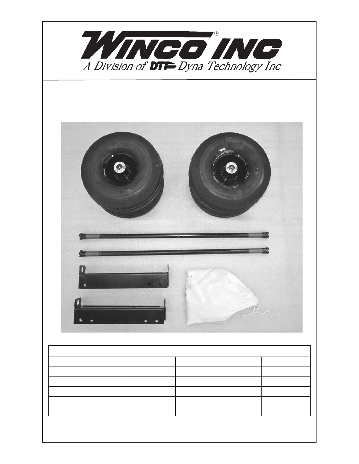
4 WHEEL DOLLY KIT
1
2
5
3
COMPONENT LIST
REF. # PART # DESCRIPTION QTY.
1 SEE NOTE BELOW 43657-003 Pneumatic Wheel & Tire 4
2 64326-019 Axle 2
3 15775-002 Axle Bracket 2
4 16199-101 Bag of Parts 1
5 16343-000 Axle Protector 4
NOTE: Foam Filled Wheel & Tire is part # 43657-004
Hard Rubber Wheel & Tire is part # 43657-005
112111-00 16199-009I
4
Page 2
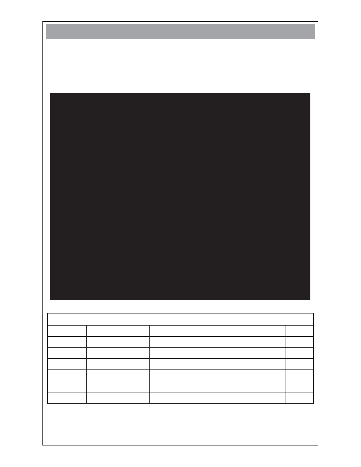
STEP 1
Open hardware bag and account for all hardware and fasteners.
•
FASTENERS & MISC. COMPONENTS
(not shown in actual size)
10
6
7
8
9
11
HARDWARE & FASTENER LIST
REF # PART # DESCRIPTION QTY
6 64688-005 Axle Stub 4
7 467-000 5/16” X 3/4” Bolt 8
8 458-000 5/16” Nut 8
9 480-000 5/16” Lock Washer 8
10 64327-000 Hub Cap 4
11 1178-000 Flat Washer 8
212111-00 16199-009I
Page 3

STEP 2
Remove the generator from the pallet or box and block generator up 8 to 10 inch-
•
es to gain access to the bottom of the cradle assembly. A lifting jack or hoist may
also be used if available.
STEP 3
•
Bolt one axle bracket (ref.3) on the engine end of the cradle and one axle bracket
(ref.3) to the generator end of the cradle using hardware (ref. 7, 9, 8). Make sure
the axle brackets are on the inside of the cradle cross-members.
Cradle depicted may not match your model.
•
ENGINE END
312111-00 16199-009I
Page 4

STEP 4
Remove and discard axle protectors (ref. 5). Tap one hubcap (ref.10) onto axle
•
(ref. 2) using a rubber mallet. Slide washer (ref. 11), wheel (ref. 1), washer (ref.
11) and axle stub (ref. 6) onto axle (ref. 2). Then slide one assembly through axle
bracket (ref. 3). Place other spacer, washer, wheel and washer on axle. Repeat
for other axle bracket.
Remove the blocks from under the cradle.
•
Tap the last two hubcaps (ref. 10) on the axles. NOTE: Do not tap too hard as
•
you may dent the hubcaps.
Cradle depicted may not match your model.
•
Winco Inc.
Service Dept.
507-357-6831
412111-00 16199-009I
 Loading...