

Page 1
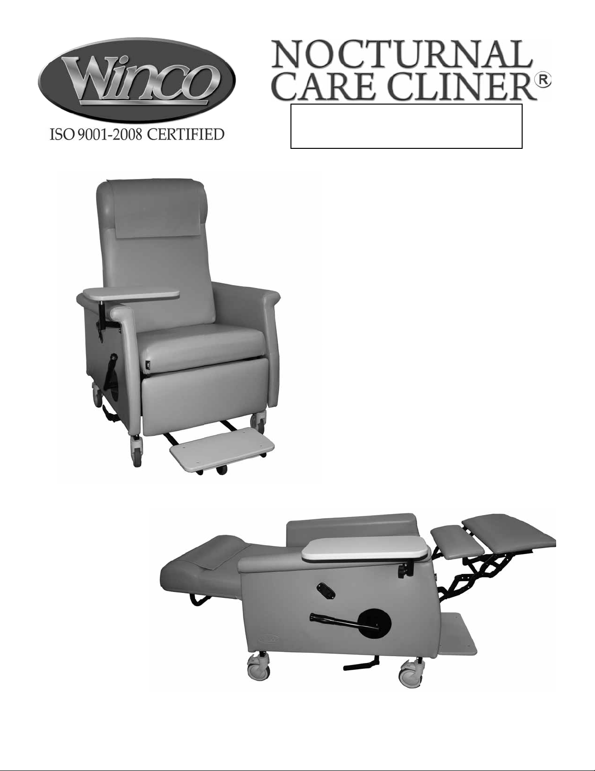
OWNER’S OPERATING &
MAINTENANCE MANUAL
For Models:
6980-6988 & 6990-6998
PLEASE DO NOT DISCARD THIS MANUAL! KEEP FOR FUTURE REFERENCE AND TRAINING
Page 2
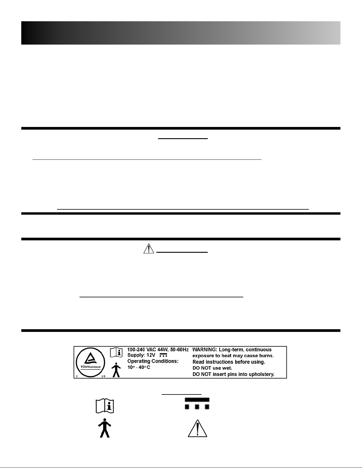
TABLE OF CONTENTS/WARRANTY
IMPORTANT SAFETY INFORMATION........................................................................................ 2-3
ASSEMBLY INSTRUCTIONS......................................................….............................................. 4
OPERATING INSTRUCTIONS............................................................................................…...... 5-7
GENERAL MAINTENANCE....................................................…….............................................. 8
SPECIFICATIONS.........................................................................................................................9
NOCTURNAL CARE CLINER OPTIONS..................................................................................... 10
CONTACT & WARRANTY INFORMATION..........................................................…....BACK COVER
UNPACKING
1. CAREFULLY EXAMINE YOUR PRODUCT FOR ANY DAMAGE. INSPECT ALL COMPONENTS.
IF DAMAGE IS EVIDENT, CONTACT FREIGHT CARRIER OR WINCO IMMEDIATELY.
2. REMOVE ALL PACKING MATERIAL AND HARDWARE THAT WAS SECURED FOR SHIPPING.
3. CAREFULLY REMOVE ALL OF THE COMPONENTS FROM THE CARTON.
4. SAVE ALL BOXES AND PACKING MATERIAL UNTIL AFTER YOU HAVE ASSEMBLED YOUR PRODUCT AND
HAVE VERIFIED THAT ALL COMPONENTS ARE FUNCTIONING PROPERLY.
(IF DAMAGE IS EVIDENT, CONTACT THE FREIGHT CARRIER OR WINCO IMMEDIATELY!)
Winco assumes no responsibility for damage or injury caused by the improper
assembly, installation, use or maintenance of these products.
IMPORTANT!
PLEASE READ THIS ENTIRE MANUAL BEFORE USING CHAIR. DO NOT INSTALL, MAINTAIN OR OPERATE THIS
EQUIPMENT WITHOUT READING AND FOLLOWING THIS MANUAL.
OTHERWISE INJURY AND/ OR DAMAGE MAY RESULT.
THE INFORMATION CONTAINED IN THIS MANUAL IS SUBJECT TO CHANGE
WITHOUT NOTICE. SAVE THESE INSTRUCTIONS FOR FUTURE REFERENCE!
NO PART OF THIS MANUAL MAY BE DUPLICATED IN ANY FORM WITHOUT THE PRIOR
CONSENT OF WINCO MFG, LLC. UNAUTHORIZED DUPLICATION MAY RESULT IN CIVIL PROSECUTION TO THE
MAXIMUM EXTENT ALLOWED BY LAW.
Products with the following markings are intended for commercial use only.
SYMBOLS
FOLLOW INSTRUCTIONS
TYPE B APPLIED PART
DC VOLTAGE
GENERAL WARNING SIGN
1
Page 3

IMPORTANT - PLEASE READ
FOR PRODUCTS WITH POWERED OPTIONS (Heat, Massage, etc...)
Read all instructions before using this product.
IMPORTANT SAFETY INSTRUCTIONS - SAVE THESE INSTRUCTIONS
To reduce the risk of electric shock when using an electrical appliance, basic precautions
should always be followed, including the following:
DANGER - Always unplug this product from the electrical outlet before cleaning, maintenance or when putting
on or taking off parts.
WARNING:
1. Unplug this product from the electrical outlet if this product is not to be used for extended periods of time.
2. Supervision should be provided when this product is used by, on, or near children, invalids, or disabled persons.
3. Use this product only for its intended use as described in this manual. Do not use attachments not recommended
by the manufacturer.
4. Never operate this product if it has a damaged cord or plug, if it is not working properly, if it has been dropped or
damaged, or dropped into water. Return the product to an authorized Winco service center.
5. DO NOT carry or pull this product by power supply cord or use the cord as a handle.
6. Keep the cord away from heated surfaces.
7. Do not use outdoors.
8. To disconnect, turn all controls to the "off" position, then remove plug from outlet. Do not "yank" cord.
9. Clean switch with a damp cloth only – Warranty will be VOID if liquid is introduced into switch mechanism.
10. Use only a certifi ed extension cord that is rated at 15 amperes; extension cords rated for less amperage may
over heat. Care should be taken to arrange the cord so that the cord cannot be pulled or tripped over.
11. DO NOT run recliner or other equipment over cord.
12. Recliner comes with a grounded three blade plug, if the plug does not fi t into the outlet; contact a certifi ed
electrician to install the proper outlet. DO NOT MODIFY THE PLUG IN ANY WAY.
DANGER:
i) Never insert pins, or attach other metallic fasteners into/onto the upholstery of this chair.
ii) Do not use this product if the covering shows signs of deterioration, such as checking, blistering, or cracking.
iii) KEEP DRY - Do not operate in a wet condition or environment.
WARNING:
i) Long term, continuous exposure to heat may cause burns. It is recommended that skin in contact with heated
area be checked for redness and blistering during long term usage. Do not use on an infant, invalid or unconscious
person. Do not use on insensitive skin or on a person with poor blood circulation. If you are uncertain if you
should use this product, please consult your physician about the use of heat and massage.
ii) Do Not Crush/Pinch heating elements or wiring.
WARNING: Connect this product to a properly grounded outlet only. (see grounding instructions, pg 3)
2
Page 4

IMPORTANT - PLEASE READ
GROUNDING INSTRUCTIONS:
This product must be grounded. If it should malfunction or breakdown, grounding provides a path of least
resistance for electric current to reduce the risk of electric shock. This product is equipped with a cord
having an equipment-grounding conductor and a grounding plug. The plug must be plugged into an
appropriate outlet that is properly installed and grounded in accordance with all local codes and
ordinances.
DANGER - Improper connection of the equipment-grounding conductor can result in a risk of electric
shock. Check with a qualifi ed electrician or serviceman if you are in doubt as to whether the product is
properly grounded. Do not modify the plug provided with the product - if it will not fi t the outlet, have a
proper outlet installed by a qualifi ed electrician.
This product is for use on a nominal 120-volt circuit and has a grounding plug. Make sure that the product
is connected to an outlet having the same confi guration as the plug. No adapter should be used with this
product.
For an added level of safety; Winco recommends the use of a 120 volt GFCI (ground fault circuit
interruptor) outlet.
DO NOT LIFT OR CHANGE CHAIR POSITION BY USING THE LEGREST.
This could injure the user or damage the recline mechanism and will void warranty.
Always change position using Release Handles on side or rear of chair.
1. READ AND FOLLOW ALL DIRECTIONS.
2. Keep children away from extended foot support (or other similiar parts).
3. NEVER STAND on slide-out foot support – foot support is not a step; Tipping of chair could
result and INJURY MAY OCCUR.
3. DO NOT put hands, feet or clothing into any openings when changing positions on recliner.
Attendant MUST confirm that users arms, legs, hands and feet are safe while changing recliner
positions or SERIOUS INJURY MAY RESULT.
4. Lock casters at all times, except when transporting chair.
5. STAY CLEAR of the recliner mechanisms.
6. DO NOT use recliner for transporting in or with ANY type of vehicle or trailer. Winco recliners
have not been tested or approved for use by an occupant in any type of vehicle or trailer.
7. NEVER use the chair arms or backrest as a seat; SERIOUS INJURY or damage may occur.
8. Periodically check the tightness of all nuts, bolts and screws.
9. Immediately REMOVE FROM SERVICE; Any recliner with broken recline
mechanisms, torn upholstery, or other mechanical or visible damage.
10. NEVER transport user with chair arms in an "open or down" position. Applies to Drop-Arm &
Swing-Arm models.
11. USE ONLY WINCO AUTHORIZED REPLACEMENT PARTS.
12. NEVER EXCEED the recommended weight capacity - see page 10.
3
Page 5

ASSEMBLY INSTRUCTIONS
FIG. 3A
FIG. 3B
BACK ASSEMBLY INSTRUCTIONS
1. Carefully remove back assembly and chair frame from
carton.
Note: Handle with care when removing chair
from box. This will ensure that no damage is
done to the cables and/or wiring that connects
the back to the chair.
2. Lock ALL (3) total-lock casters on chair base. (see Lock/
Unlock Casters page 6).
NOTE: Make sure the footrest is in closed position
before installing the back.
3. Cut the "zip-tie notice tag" on the back
mechanism fork, located behind the seat.
4. Pull UP on the back adjustment handle (FIG.2A) to
bring the back mechanism (FIG.2B) into its upright
position.
FIG. 1
5. Using 2 people
the Push Handle on the back, and hold the back in
(RECOMMENDED), have one person grab
FIG. 2
position over mounting forks. Align the forks on base
(FIG. 3A) with the guides on back (FIG. 3B).
FIG. 3
6. Slide the guides onto the mounting forks until the guides
"SNAP" or click into their proper location.
FIG. 3B
(Circled, FIG.3A).
7. Once the back has been tested for proper installation,
close the "hook & loop" flaps.
IMPORTANT
FIG. 3A
Test to ensure the back has been properly installed by pulling up on
the back's push handle.
The back should remain securely in place
IMPORTANT
REGULARLY lubricate pivot points on the Recline Mechanism with a silicone based lubricant.
Once per week, position the Chair Back into full recline position, squeeze release handle and go to full Trendelenburg
position. This will keep the gas cylinder lubricated.
Periodically recheck tightness of all screws, bolts and nuts.
4
Page 6

OPERATING INSTRUCTIONS
RECLINING THE CARE CLINER & TRENDELENBURG
(Figures 3 & 4-1 are attendant operated ONLY)
1. LEGREST ELEVATION: From the "SEATED UPRIGHT"
position, grip the Legrest Handle and pull towards the
back of the chair until handle stops (FIG.1).
2. The back can be adjusted to infinite recline positions.
To do so, lift the Back Release Handle, then position
the chair Back to the desired position and release the
handle (FIG.2).
Attendants can also adjust the recline position by pulling
up on the Back Release Handle located in on back of chair
under the push handle (FIG. 3).
3. TRENDELENBURG (or lowering the back farther than the
positions specified in the above steps) CAN ONLY BE
PERFORMED BY AN ATTENDANT. (FIG. 4, #1 & #2)
To LOWER the Back into the Trendelenburg position:
Recline the chair to full recline; Depress the Foot Lever
(FIG. 4, #1) and continue to push Back down to the
Trendelenburg position. (FIG. 4, #2)
Lift foot off of lever once Trendelenburg position is
achieved.
FIG. 1
FIG. 2
4. To RAISE the chair Back upwards from Trendelenburg:
Pull up on the back. (FIG. 4, #2)
For further upward adjustment, pull out on either Back
Release Handle (FIG. 2 or 3) until the desired position
is reached, or until chair back is fully upright.
DO NOT FORCE back of chair downward without
engaging either of the two Release Handles. This can
damage the chair. The chair back will stay in any position
when you remove your hand from the handles.
NOTE: If the chair back does not recline when the Back Release
Handle is pulled, or does not remain in the correct reclined position
when the Release Handle is released, cable tension must be adjusted.
Refer to Adjusting Gas Spring on page 8.
DO NOT push or pull footrest to position chair.
DO NOT stand or sit on the footrest.
DO NOT place hands, legs or feet under seat, legrest
or footrest. Stay clear of recline mechanism.
KEEP CHILDREN AWAY from the underside of chair. Injury may occur.
5
FIG. 3
FIG. 4
Page 7

OPERATING INSTRUCTIONS (cont'd)
LOCK/ UNLOCK CASTERS (Total-Lock vs. Directional)
1. Total-Lock casters will lock wheel and swivel mechanism
by using your foot & pushing down on the tab. Both front
and the right-rear casters are Total-Locks. These are
identified with lighter gray tabs.
Directional caster is used to help steer the chair (Left rear
only). The tab locks the swivel mechanism; The wheel
does not lock on this caster. It is identified with a darker
gray tab. (FIG. 1)
FIG. 1
FIG. 2
2. Release the locking mechanisms by pushing the above
described tabs back to horizontal position.
(FIG. 2 to FIG. 1)
TO POSITION SIDE TABLE
1. To raise table, grasp center of table and gently raise into
place. Table will automatically lock into place when
released. (FIG. 3)
2. To lower table, grasp table at the center, raise and pivot
down in one movement.
TO POSITION PIVOT TABLE
1. To adjust the pivot table position, loosen the adjustment
knob and swing away or place in the "lap" position. Tighten
knob to secure position. (FIG. 4)
2. To remove pivot table from chair, loosen the adjustment
knob and pull up on pivot table.
FIG. 3
FIG. 4
SWING-ARM OPERATION
TO OPEN: Depress red latch handle to unlock Swing-Arm
TO CLOSE: Push Swing-Arm into latch.
Latch will automaticallly engage.
DO NOT lean or sit on side tables. Tables may
break and cause injury.
DO NOT allow patients to raise from chair using
side tables.
DO NOT allow weight to be placed on open
swing-arms. Arms may become damaged and fail
to close or latch properly.
6
Page 8
OPERATING INSTRUCTIONS (cont'd)
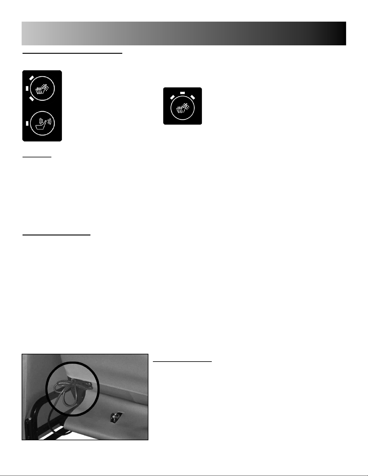
HEAT & MASSAGE OPTIONS
Control is located on the inside of right arm of chair.
HEAT
OR
MASSAGE
Heating: Push HEAT button - See indicator light on switch
3 Lights = High Heat / Bright Light
2 Lights = Medium Heat / Med Light
1 Lights = Low Heat / Dim Light
No Light = HEAT OFF
Allow 5-8 minutes for back and seat to warm to desired TEMP. setting.
Heat will automatically shut off after approximately 60 minutes.
Massage (optional): Push MASSAGE button
1X = Lower Back / Low Intensity
2X = Lower Back / High Intensity
3X = Upper & Lower Back / Low Intensity
4X = Upper & Lower Back / High Intensity
5X = Alternating Upper & Lower Back / High Intensity
6X = MASSAGE OFF
Massage will automatically shut off after approximately 15 minutes.
HEAT ONLY
(Timer resets when switch is pressed)
(Timer resets when switch is pressed)
• Use a DAMP CLOTH ONLY to clean switch, wiring or power pack (located under seat frame).
• If there is no heat or massage or flashing light on switch - check power cord connections to wall
outlet AND connection of power cord to power pack unit under chair.
• If switch displays a flashing light; Check all accessible wire connectors under chair for possible
loose connections, then contact Winco customer service: 1-800-237-3377.
CORD STORAGE
(Models with Heat-HT or Heat & Massage-HM)
1. Before transporting chair, or when heat & massage is
not in use, power cord should be coiled and stored in
the "Hook & Loop" fastener provided as shown, to
prevent tripping on cord, damage to cord, damage to
recliner, etc... (FIG. 1)
FIG. 1
7
Page 9

GENERAL MAINTENANCE
ADJUSTING GAS SPRING
NOTE: Tension or "ease of movement" of the gas spring is set by factory and cannot be
changed.
1. Using 2 people (RECOMMENDED), tilt the chair over onto the Left side
and locate the Gas Spring (FIG. 1). Loosen the 11/16" hex nut on the
Gas Spring located near the bottom-front of the chair. (FIG.2)
2. On the opposite end of Gas Spring, remove the Bow-Tie
Cotter Pin and Clevis Pin - (save the 2 plastic Clevis Pin bushings)
(FIG.3) Gas Spring can now be rotated for adjustment.
3. If Back of chair will not recline when "back release handles" are lifted
then you will need to Rotate the Gas Spring as shown, clockwise, one
half (1/2) of a revolution (or 180 degrees) - see (FIG. 4A). If Back of
chair reclines without lifting handles; then you will need to Rotate Gas
Spring as shown, counter-clockwise, one-half (1/2) of a revolution
(or 180 degrees). (FIG. 4B)
4. Once you make an adjustment; Replace Clevis Pin, plastic bushings
and Bow-Tie Cotter Pin. Pull up on the Back Adjustment Handle to
check for proper adjustment. Repeat above steps as needed until
correct release action is achieved. Then TIGHTEN HEX NUT (that you
loosened in step 1) once the Gas Spring is adjusted properly.
~Make sure all bow tie cotter pins are securely inserted in all clevis pins
and that cable end is attached through slot of Operator.
~Failure to securely insert the bow tie cotter pins into the clevis pin
could cause the clevis pins to fall out and result in injury, or damage to
the chair.
FIG. 1
FIG. 2
FIG. 3
FIG. 4
GENERAL CARE & CLEANING
Remove hair & body oils; Your recliner should be cleaned with mild soap & water solution and a damp cloth on a regular
basis (especially where skin & hair make contact with upholstery). Avoid harsh detergents or chemicals that could
damage the upholstery or finish of your recliner. If the recliner is disenfected, the chair MUST be wiped off with ONLY
clean water on a damp cloth.
Note: Disinfectants alone, will not provide adequate "grease or oil cutting" properties to remove hair & skin oils. Over
time, the appearance and feel of your upholstery may diminish if not cleaned
properly.
Please refer to the PERMABLOK instruction tag that is attached to your Care Cliner for complete care and cleaning
instructions. Retain information on tag for future use.
FOR FURTHER CLEANING INFORMATION VISIT:
http://www.wincomfg.com/permablok-info-and-cleaning-instructions
8
Page 10
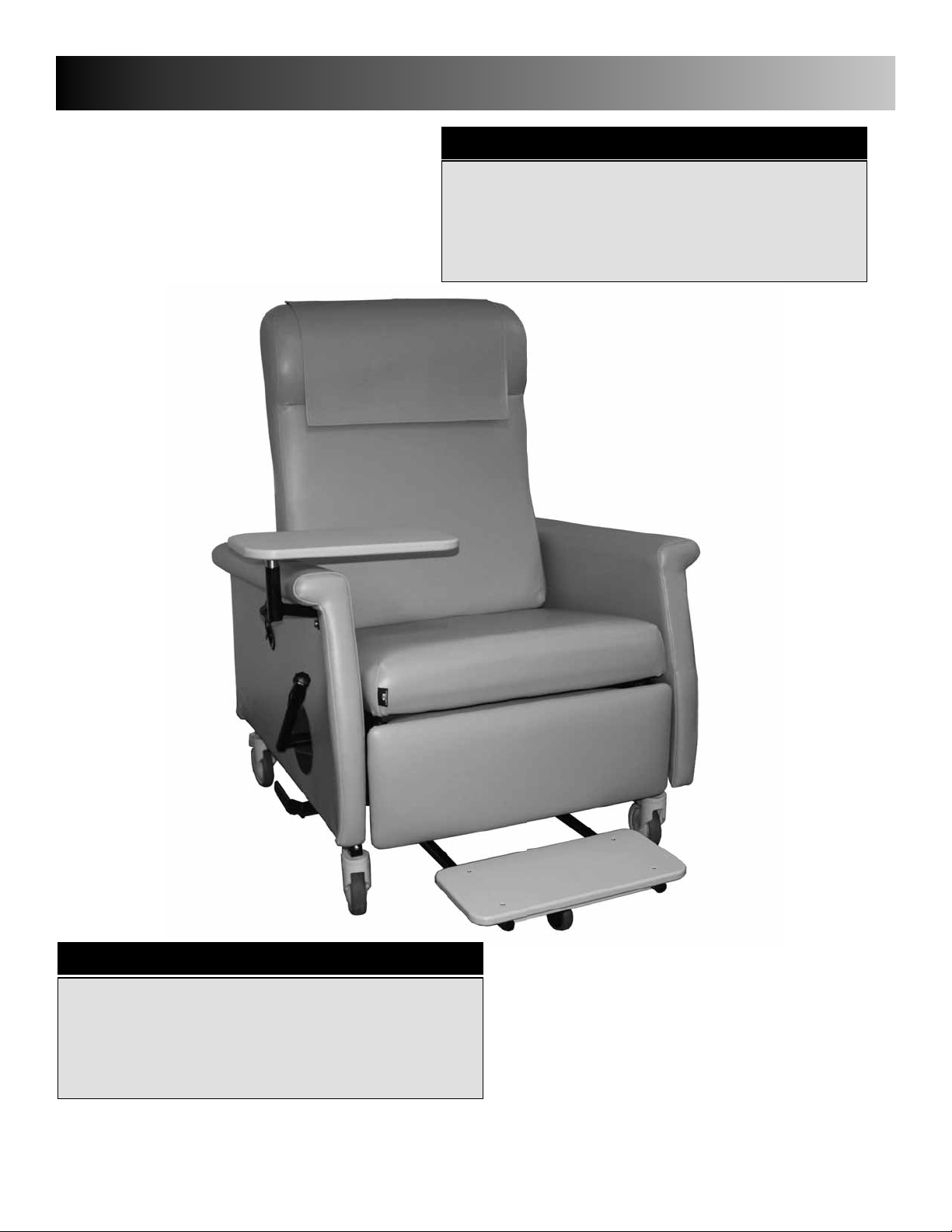
6980 & 6990 SPECIFICATIONS
6980 - Specifications
Seat Height ...........................23.5"
to Footrest Plate...........16.5"
Seat Width...............................21"
Overall Height ........................52.5"
Overall Width (Trays Down)...34.5"
(Trays Up)........44"
Maximum Weight Capacity....350 lbs.
Back Height Above Seat......32.5"
Seat Depth...........................21.5"
Weight .................................167 lbs.
6990 - Specifications
Seat Height ...........................23.5"
to Footrest Plate...........16.5"
Seat Width (arm to arm).........28"
Overall Height ........................52.5"
Overall Width (Trays Down)...39.5"
(Trays Up)........49"
Maximum Weight Capacity....500 lbs.
Back Height Above Seat......32.5"
Seat Depth...........................21.5"
Weight .................................174 lbs.
9
Page 11

NOCTURNAL CARE CLINER OPTIONS
Heat & Massage
HM .....................................Heat & Massage
HT ..............................................Heat ONLY
FACTORY INSTALLED ONLY
Armrest Covers
AC00..............................Armrest Covers (Pair)
IV Pole & Attachment
IV................................ IV Pole & Attachment
Side Cushion
SC00............................................Side Cushion
Oxygen Tank Holder
O2.....................................Oxygen Tank Holder
10
Page 12

LIMITED WARRANTY
Winco Mfg., LLC. warrants this product to be free of manufacturer’s defects in material and workmanship, provided that the product is used according to normal operating conditions and proper maintenance intended by manufacturer. This warranty is available only to the original retail
purchaser, is non-transferable and commences on the date of retail sale; proof of purchase required.
LIMITED ONE YEAR COMPLETE PRODUCT WARRANTY: Winco Mfg., LLC warrants the complete product for one (1) year.
At Winco Mfg., LLC. sole discretion, it may repair or replace any components freight free that are
found to be defective during the fi rst year. Winco Mfg., LLC. shall not be liable for any labor, or any
other costs incurred as a result of or in conjunction with a warranty claim.
LIMITED THREE YEAR WARRANTY: Winco Mfg., LLC warrants recliner mechanisms, electrical components, vinyl panels and
Vinyl on upholstered parts [from cracking or delaminating] pressurized gas springs, and casters, when
new, for a period of three (3) years. At Winco Mfg., LLC.’s Sole discretion, it may repair or replace
components found to be defective. Winco Mfg., LLC. shall not be liable for any labor, shipping or any
other costs incurred as a result of or in conjunction with a warranty claim.
LIMITED LIFETIME CHAIR FRAME WARRANTY: Winco Mfg., LLC warrants steel and aluminum base frames for all products,
when new, for the lifetime of the original purchaser. This limited warranty does not apply to
paint/fi nish or any components attached to the frame such as; upholstery, foam, casters, mechanisms
or related parts that are covered under above warranties. Winco Mfg., LLC shall not be liable for any
labor, shipping or any other costs incurred as a result of or in conjunction with a warranty claim.
The purchaser’s exclusive remedy under this warranty shall be limited to such repair or replacement of defective components
at Winco Mfg., LLC sole discretion. For warranty service, contact the dealer that the product was originally purchased from or
Winco Mfg., LLC directly.
EXCLUSIONS
There are no other warranties, conditions, representations or guarantees, express or implied, made or intended by Winco Mfg., LLC and all other
warranties, conditions, representations or guarantees including any warranties, conditions, representations or guarantees under any Sale of
Good Act or Like legislation or statute is hereby expressly excluded. Any and all other implied warranties shall not extend beyond the duration of
the express warranty. Liability for incidental or consequential damages is excluded to the extent permitted by law. Some states do not allow the
exclusion or limitation so the above limitation or exclusion may not apply to you. This warranty gives you specifi c legal rights. In addition you may
also have other rights, which vary from state to state.
TERMS
No warranty herein contained or set out shall apply when damage or repair is caused by any of the following:
1. Damage in transit.
2. Accident, alteration, abuse or misuse of product i.e. exceeding weight capacities, applying inordinate pressure to footrest/leg rest, use
in Mental Health facilities like institutions or, any unintended use of the product or use in unintended environments
(i.e. outdoor, showers, MRI rooms, etc..)
3. Fire, water damage, theft, war, riot, hostility, acts of God.
Examples contained in this list are not to be construed as all-inclusive.
Design, appearance, parts, & construction are subject to change without notice
5516 Southwest 1st Lane
Ocala, Florida 34474
1-800-237-3377/ 352-854-2929/ Fax: 352-854-9544
e-mail: customerservice@wincomfg.com
GENERAL PROVISIONS
www.wincomfg.com
#006306 REV N 06-27-13 JWC
 Loading...