


Winbond W25Q64FWBYIG, W25Q64FWBYIP, W25Q64FWSFIG, W25Q64FWSFIP, W25Q64FWSSIG Schematic [ru]
...W25Q64FW
1.8V 64M-BIT
SERIAL FLASH MEMORY WITH DUAL/QUAD SPI & QPI
Publication Release Date: March 25, 2013
Preliminary - Revision D

|
|
|
|
W25Q64FW |
|
|
|
Table of Contents |
|
1. |
GENERAL DESCRIPTIONS............................................................................................................. |
5 |
||
2. |
FEATURES |
....................................................................................................................................... |
5 |
|
3. |
PACKAGE TYPES ..........................................................................AND PIN CONFIGURATIONS |
6 |
||
|
3.1 |
Pin Configuration ..............................................................................SOIC / VSOP 208-mil |
6 |
|
|
3.2 |
Pad ......................................................................Configuration WSON 6x5-mm / 8x6-mm |
6 |
|
|
3.3 |
Pin Description ........................................SOIC/VSOP 208-mil, WSON 6x5-mm / 8x6-mm |
6 |
|
|
3.4 |
Pin Configuration ...........................................................................................SOIC 300-mil |
7 |
|
|
3.5 |
Pin Description ...............................................................................................SOIC 300-mil |
7 |
|
|
3.6 |
Ball Configuration .................................................TFBGA 8x6-mm (5x5 or 6x4 Ball Array) |
8 |
|
|
3.7 |
Ball Description .........................................................................................TFBGA 8x6-mm |
8 |
|
|
3.8 |
Ball Configuration ...................................................................................................WLBGA |
9 |
|
|
3.9 |
Ball Description ......................................................................................................WLBGA |
9 |
|
4. |
PIN DESCRIPTIONS...................................................................................................................... |
10 |
||
|
4.1 |
Chip ................................................................................................................Select (/CS) |
10 |
|
|
4.2 |
Serial ..................................Data Input, Output and IOs (DI, DO and IO0, IO1, IO2, IO3) |
10 |
|
|
4.3 |
Write .............................................................................................................Protect (/WP) |
10 |
|
|
4.4 |
HOLD ...................................................................................................................(/HOLD) |
10 |
|
|
4.5 |
Serial ..............................................................................................................Clock (CLK) |
10 |
|
|
4.6 |
Reset ..................................................................................................................(/RESET) |
10 |
|
5. |
BLOCK DIAGRAM.......................................................................................................................... |
11 |
||
6. |
FUNCTIONAL .....................................................................................................DESCRIPTIONS |
12 |
||
|
6.1 |
SPI / ..........................................................................................................QPI Operations |
12 |
|
|
|
6.1.1 ..................................................................................................... |
Standard SPI Instructions |
12 |
|
|
6.1.2 ............................................................................................................ |
Dual SPI Instructions |
12 |
|
|
6.1.3 ........................................................................................................... |
Quad SPI Instructions |
13 |
|
|
6.1.4 .................................................................................................................... |
QPI Instructions |
13 |
|
|
6.1.5 ........................................................................................................................ |
Hold Function |
13 |
|
|
6.1.6 ..............................................................................Software Reset & Hardware /RESET pin |
14 |
|
|
6.2 |
Write ..................................................................................................................Protection |
15 |
|
|
|
6.2.1 .......................................................................................................... |
Write Protect Features |
15 |
7. |
STATUS AND ............................................................................CONFIGURATION REGISTERS |
16 |
||
|
7.1 |
Status .................................................................................................................Registers |
16 |
|
|
|
7.1.1 ....................................................................Erase/Write In Progress (BUSY) – Status Only |
16 |
|
|
|
7.1.2 ..............................................................................Write Enable Latch (WEL) – Status Only |
16 |
|
|
|
7.1.3 ....................................Block Protect Bits (BP2, BP1, BP0) – Volatile/Non-Volatile Writable |
16 |
|
- 1 -

W25Q64FW
|
|
7.1.4 Top/Bottom Block Protect (TB) – Volatile/Non-Volatile Writable ........................................... |
17 |
|
|
|
7.1.5 Sector/Block Protect Bit (SEC) – Volatile/Non-Volatile Writable ........................................... |
17 |
|
|
|
7.1.6 Complement Protect (CMP) – Volatile/Non-Volatile Writable................................................ |
17 |
|
|
|
7.1.7 Status Register Protect (SRP1, SRP0) – Volatile/Non-Volatile Writable............................... |
17 |
|
|
|
7.1.8 Erase/Program Suspend Status (SUS) – Status Only .......................................................... |
18 |
|
|
|
7.1.9 Security Register Lock Bits (LB3, LB2, LB1, LB0) – Volatile/Non-Volatile OTP Writable...... |
18 |
|
|
|
7.1.10 Quad Enable (QE) – Volatile/Non-Volatile Writable ............................................................ |
18 |
|
|
|
7.1.11 Write Protect Selection (WPS) – Volatile/Non-Volatile Writable.......................................... |
19 |
|
|
|
7.1.12 Output Driver Strength (DRV1, DRV0) – Volatile/Non-Volatile Writable ............................. |
19 |
|
|
|
7.1.13 HOLD or /RESET Pin Function (HOLD/RST) – Volatile/Non-Volatile Writable ................... |
19 |
|
|
|
7.1.14 Reserved Bits – Non Functional ......................................................................................... |
19 |
|
|
|
7.1.15 W25Q64FW Status Register Memory Protection (WPS = 0, CMP = 0) .............................. |
20 |
|
|
|
7.1.16 W25Q64FW Status Register Memory Protection (WPS = 0, CMP = 1) .............................. |
21 |
|
|
|
7.1.17 W25Q64FW Individual Block Memory Protection (WPS=1)................................................ |
22 |
|
8. |
INSTRUCTIONS............................................................................................................................. |
23 |
||
|
8.1 |
Device ID and Instruction Set Tables ................................................................................. |
23 |
|
|
|
8.1.1 Manufacturer and Device Identification................................................................................. |
23 |
|
|
|
8.1.2 Instruction Set Table 1 (Standard/Dual/Quad SPI Instructions) ............................................ |
24 |
|
|
|
8.1.3 Instruction Set Table 2 (Standard/Dual/Quad SPI Instructions) ............................................ |
25 |
|
|
|
8.1.4 Instruction Set Table 3 (QPI Instructions) ............................................................................. |
26 |
|
|
8.2 |
Instruction Descriptions ...................................................................................................... |
28 |
|
|
|
8.2.1 |
Write Enable (06h) ................................................................................................................ |
28 |
|
|
8.2.2 Write Enable for Volatile Status Register (50h)..................................................................... |
28 |
|
|
|
8.2.3 |
Write Disable (04h) ............................................................................................................... |
29 |
|
|
8.2.4 Read Status Register-1 (05h), Status Register-2 (35h) & Status Register-3 (15h) ............... |
29 |
|
|
|
8.2.5 Write Status Register-1 (01h), Status Register-2 (31h) & Status Register-3 (11h) ............... |
30 |
|
|
|
8.2.6 |
Read Data (03h) ................................................................................................................... |
33 |
|
|
8.2.7 |
Fast Read (0Bh) ................................................................................................................... |
34 |
|
|
8.2.8 Fast Read Dual Output (3Bh) ............................................................................................... |
36 |
|
|
|
8.2.9 Fast Read Quad Output (6Bh) .............................................................................................. |
37 |
|
|
|
8.2.10 Fast Read Dual I/O (BBh) ................................................................................................... |
38 |
|
|
|
8.2.11 Fast Read Quad I/O (EBh) ................................................................................................. |
40 |
|
|
|
8.2.12 Word Read Quad I/O (E7h) ................................................................................................ |
43 |
|
|
|
8.2.13 Octal Word Read Quad I/O (E3h) ....................................................................................... |
45 |
|
|
|
8.2.14 Set Burst with Wrap (77h)................................................................................................... |
47 |
|
|
|
8.2.15 |
Page Program (02h) ........................................................................................................... |
48 |
|
|
8.2.16 Quad Input Page Program (32h)......................................................................................... |
50 |
|
|
|
8.2.17 |
Sector Erase (20h).............................................................................................................. |
51 |
|
|
8.2.18 32KB Block Erase (52h)...................................................................................................... |
52 |
|
|
|
8.2.19 64KB Block Erase (D8h) ..................................................................................................... |
53 |
|
|
Publication Release Date: March 25, 2013 |
- 2 - |
Preliminary - Revision D |

|
|
|
W25Q64FW |
|
|
8.2.20 Chip Erase (C7h / 60h) ....................................................................................................... |
54 |
|
|
8.2.21 Erase / Program Suspend (75h) ......................................................................................... |
55 |
|
|
8.2.22 Erase / Program Resume (7Ah).......................................................................................... |
57 |
|
|
8.2.23 Power-down (B9h) .............................................................................................................. |
58 |
|
|
8.2.24 Release Power-down / Device ID (ABh) ............................................................................. |
59 |
|
|
8.2.25 Read Manufacturer / Device ID (90h) ................................................................................. |
61 |
|
|
8.2.26 Read Manufacturer / Device ID Dual I/O (92h) ................................................................... |
62 |
|
|
8.2.27 Read Manufacturer / Device ID Quad I/O (94h).................................................................. |
63 |
|
|
8.2.28 Read Unique ID Number (4Bh)........................................................................................... |
64 |
|
|
8.2.29 Read JEDEC ID (9Fh) ........................................................................................................ |
65 |
|
|
8.2.30 Erase Security Registers (44h) ........................................................................................... |
66 |
|
|
8.2.31 Program Security Registers (42h)....................................................................................... |
67 |
|
|
8.2.32 Read Security Registers (48h) ............................................................................................ |
68 |
|
|
8.2.33 Set Read Parameters (C0h) ............................................................................................... |
69 |
|
|
8.2.34 Burst Read with Wrap (0Ch) ............................................................................................... |
70 |
|
|
8.2.35 Enter QPI Mode (38h)......................................................................................................... |
71 |
|
|
8.2.36 Exit QPI Mode (FFh)........................................................................................................... |
72 |
|
|
8.2.37 Individual Block/Sector Lock (36h)...................................................................................... |
73 |
|
|
8.2.38 Individual Block/Sector Unlock (39h) .................................................................................. |
74 |
|
|
8.2.39 Read Block/Sector Lock (3Dh)............................................................................................ |
75 |
|
|
8.2.40 Global Block/Sector Lock (7Eh) .......................................................................................... |
76 |
|
|
8.2.41 Global Block/Sector Unlock (98h) ....................................................................................... |
76 |
|
|
8.2.42 Enable Reset (66h) and Reset Device (99h) ...................................................................... |
77 |
9. |
ELECTRICAL CHARACTERISTICS .............................................................................................. |
78 |
|
|
9.1 |
Absolute Maximum Ratings................................................................................................ |
78 |
|
9.2 |
Operating Ranges .............................................................................................................. |
78 |
|
9.3 |
Power-up Power-down Timing and Requirements ............................................................ |
79 |
|
9.4 |
DC Electrical Characteristics.............................................................................................. |
80 |
|
9.5 |
AC Measurement Conditions ............................................................................................. |
81 |
|
9.6 |
AC Electrical Characteristics .............................................................................................. |
82 |
|
9.7 |
AC Electrical Characteristics (cont’d)................................................................................. |
83 |
|
9.8 |
Serial Output Timing........................................................................................................... |
84 |
|
9.9 |
Serial Input Timing.............................................................................................................. |
84 |
|
9.10 |
HOLD Timing...................................................................................................................... |
84 |
|
9.11 |
WP Timing .......................................................................................................................... |
84 |
10. |
PACKAGE SPECIFICATIONS ....................................................................................................... |
85 |
|
|
10.1 |
8-Pin SOIC 208-mil (Package Code SS) ........................................................................... |
85 |
|
10.2 |
8-Pin VSOP 208-mil (Package Code ST) .......................................................................... |
86 |
|
10.3 |
8-Pad WSON 6x5-mm (Package Code ZP)....................................................................... |
87 |
- 3 -

|
|
|
W25Q64FW |
|
10.4 |
8-Pad WSON 8x6-mm (Package Code ZE)....................................................................... |
88 |
|
10.5 |
16-Pin SOIC 300-mil (Package Code SF).......................................................................... |
89 |
|
10.6 |
24-Ball TFBGA 8x6-mm (Package Code TB, 5x5-1 ball array) ......................................... |
90 |
|
10.7 |
24-Ball TFBGA 8x6-mm (Package Code TC, 6x4 ball array) ............................................ |
91 |
|
10.8 |
16-Ball WLBGA (Package Code BY) ................................................................................. |
92 |
11. |
ORDERING INFORMATION .......................................................................................................... |
93 |
|
|
11.1 |
Valid Part Numbers and Top Side Marking........................................................................ |
94 |
12. |
REVISION HISTORY...................................................................................................................... |
95 |
|
|
Publication Release Date: March 25, 2013 |
- 4 - |
Preliminary - Revision D |

W25Q64FW
1. GENERAL DESCRIPTIONS
The W25Q64FW (64M-bit) Serial Flash memory provides a storage solution for systems with limited space, pins and power. The 25Q series offers flexibility and performance well beyond ordinary Serial Flash devices. They are ideal for code shadowing to RAM, executing code directly from Dual/Quad SPI (XIP) and storing voice, text and data. The device operates on a single 1.65V to 1.95V power supply with current consumption as low as 4mA active and 1µA for power-down. All devices are offered in spacesaving packages.
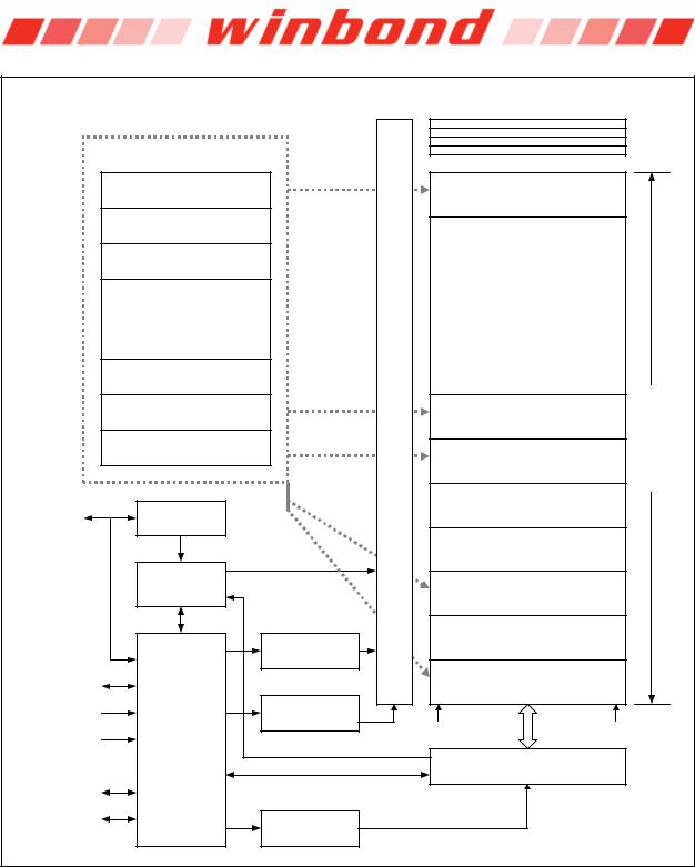
The W25Q64FW array is organized into 32,768 programmable pages of 256-bytes each. Up to 256 bytes can be programmed at a time. Pages can be erased in groups of 16 (4KB sector erase), groups of 128 (32KB block erase), groups of 256 (64KB block erase) or the entire chip (chip erase). The W25Q64FW has 4,096 erasable sectors and 256 erasable blocks respectively. The small 4KB sectors allow for greater flexibility in applications that require data and parameter storage. (See Figure 2.)
The W25Q64FW support the standard Serial Peripheral Interface (SPI), Dual/Quad I/O SPI as well as 2- clocks instruction cycle Quad Peripheral Interface (QPI): Serial Clock, Chip Select, Serial Data I/O0 (DI), I/O1 (DO), I/O2 (/WP), and I/O3 (/HOLD). SPI clock frequencies of up to 104MHz are supported allowing equivalent clock rates of 208MHz (104MHz x 2) for Dual I/O and 416MHz (104MHz x 4) for Quad I/O when using the Fast Read Dual/Quad I/O and QPI instructions. These transfer rates can outperform standard Asynchronous 8 and 16-bit Parallel Flash memories. The Continuous Read Mode allows for efficient memory access with as few as 8-clocks of instruction-overhead to read a 24-bit address, allowing true XIP (execute in place) operation.
A Hold pin, Write Protect pin and programmable write protection, with top or bottom array control, provide further control flexibility. Additionally, the device supports JEDEC standard manufacturer and device ID, a 64-bit Unique Serial Number and three 256-bytes Security Registers.
2.FEATURES
New Family of SpiFlash Memories
–W25Q64FW: 64M-bit / 8M-byte
–Standard SPI: CLK, /CS, DI, DO, /WP, /Hold
–Dual SPI: CLK, /CS, IO0, IO1, /WP, /Hold
–Quad SPI: CLK, /CS, IO0, IO1, IO2, IO3
–QPI: CLK, /CS, IO0, IO1, IO2, IO3
–Software & Hardware Reset
Highest Performance Serial Flash
–104MHz Single, Dual/Quad SPI clocks
–208/416MHz equivalent Dual/Quad SPI
–50MB/S continuous data transfer rate
–More than 100,000 erase/program cycles
–More than 20-year data retention
Efficient “Continuous Read” and QPI Mode
–Continuous Read with 8/16/32/64-Byte Wrap
–As few as 8 clocks to address memory
–Quad Peripheral Interface (QPI) reduces instruction overhead
–Allows true XIP (execute in place) operation
–Outperforms X16 Parallel Flash
Low Power, Wide Temperature Range
–Single 1.65 to 1.95V supply
–4mA active current, <1µA Power-down (typ.)
–-40°C to +85°C operating range
Flexible Architecture with 4KB sectors
–Uniform Sector/Block Erase (4K/32K/64K-Byte)
–Program 1 to 256 byte per programmable page
–Erase/Program Suspend & Resume
Advanced Security Features
–Software and Hardware Write-Protect
–Power Supply Lock-Down and OTP protection
–Top/Bottom, Complement array protection
–Individual Block/Sector array protection
–64-Bit Unique ID for each device
–4X256-Bytes Security Registers with OTP locks
–Volatile & Non-volatile Status Register Bits
Space Efficient Packaging
–8-pin SOIC/VSOP 208-mil
–8-pad WSON 6x5-mm / 8x6-mm
–16-pin SOIC 300-mil (additional /RESET pin)
–16-ball WLBGA
–24-ball TFBGA 8x6-mm
–Contact Winbond for KGD and other options
- 5 -
W25Q64FW
3. PACKAGE TYPES AND PIN CONFIGURATIONS
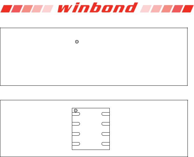
3.1 Pin Configuration SOIC / VSOP 208-mil
|
|
|
|
Top View |
|
|
|
|
|
|
|
|
|
|
|
|
|
|
|
|
|
|
|
/CS |
|
|
1 |
8 |
|
|
VCC |
|
|
||||||
DO (IO1) |
|
|
2 |
7 |
|
|
/HOLD or /RESET |
|
|
|
|
(IO3) |
|||
|
|
||||||
|
|
|
|
|
|
|
|
/WP (IO2) |
|
|
3 |
6 |
|
|
CLK |
|
|
||||||
GND |
|
|
4 |
5 |
|
|
DI (IO0) |
|
|
||||||
|
|
||||||
|
|
|
|
|
|
|
|
|
|
|
|
|
|
|
|
Figure 1a. W25Q64FW Pin Assignments, 8-pin SOIC / VSOP 208-mil (Package Code SS, ST)
3.2 Pad Configuration WSON 6x5-mm / 8x6-mm
|
Top View |
|
||
/CS |
1 |
8 |
VCC |
|
DO (IO1) |
2 |
7 |
/HOLD or /RESET |
|
(IO3) |
||||
|
|
|
||
/WP (IO2) |
3 |
6 |
CLK |
|
GND |
4 |
5 |
DI (IO0) |
|
Figure 1b. W25Q64FW Pad Assignments, 8-pad WSON 6x5-mm / 8x6-mm (Package Code ZP, ZE)
3.3Pin Description SOIC/VSOP 208-mil, WSON 6x5-mm / 8x6-mm
PIN NO. |
PIN NAME |
I/O |
FUNCTION |
|
|
|
|
1 |
/CS |
I |
Chip Select Input |
|
|
|
|
2 |
DO (IO1) |
I/O |
Data Output (Data Input Output 1)(1) |
3 |
/WP (IO2) |
I/O |
Write Protect Input ( Data Input Output 2)(2) |
4 |
GND |
|
Ground |
|
|
|
|
5 |
DI (IO0) |
I/O |
Data Input (Data Input Output 0)(1) |
6 |
CLK |
I |
Serial Clock Input |
|
|
|
|
7 |
/HOLD or /RESET |
I/O |
Hold or Reset Input (Data Input Output 3)(2) |
|
(IO3) |
|
|
|
|
|
|
8 |
VCC |
|
Power Supply |
|
|
|
|
|
|
|
|
Notes:
1.IO0 and IO1 are used for Standard and Dual SPI instructions
2.IO0 –IO3 are used for Quad SPI instructions, /WP & /HOLD (or /RESET) functions are only available for Standard/Dual SPI.
|
Publication Release Date: March 25, 2013 |
- 6 - |
Preliminary - Revision D |

W25Q64FW
3.4Pin Configuration SOIC 300-mil
|
|
|
|
Top View |
|
|
|
|
|
|
|
|
|
|
|
/HOLD (IO3) |
|
|
1 |
16 |
|
|
CLK |
|
|
||||||
VCC |
|
|
2 |
15 |
|
|
DI (IO0) |
|
|
||||||
|
|
||||||
/RESET |
|
|
3 |
14 |
|
|
NC |
|
|
||||||
NC |
|
|
4 |
13 |
|
|
NC |
|
|
||||||
NC |
|
|
5 |
12 |
|
|
NC |
|
|
||||||
NC |
|
|
6 |
11 |
|
|
NC |
|
|
||||||
/CS |
|
|
7 |
10 |
|
|
GND |
|
|
||||||
DO (IO1) |
|
|
8 |
9 |
|
|
/WP (IO2) |
|
|
||||||
|
|
||||||
|
|
|
|
|
|
|
|
|
|
|
|
|
|
|
|
Figure 1c. W25Q64FW Pin Assignments, 16-pin SOIC 300-mil (Package Code SF)
3.5Pin Description SOIC 300-mil
PIN NO. |
PIN NAME |
I/O |
FUNCTION |
|
|
|
|
1 |
/HOLD (IO3) |
I/O |
Hold Input (Data Input Output 3)(2) |
2 |
VCC |
|
Power Supply |
|
|
|
|
3 |
/RESET |
I |
Reset Input(3) |
4 |
N/C |
|
No Connect |
|
|
|
|
5 |
N/C |
|
No Connect |
|
|
|
|
6 |
N/C |
|
No Connect |
|
|
|
|
7 |
/CS |
I |
Chip Select Input |
|
|
|
|
8 |
DO (IO1) |
I/O |
Data Output (Data Input Output 1)(1) |
9 |
/WP (IO2) |
I/O |
Write Protect Input (Data Input Output 2)(2) |
10 |
GND |
|
Ground |
|
|
|
|
11 |
N/C |
|
No Connect |
|
|
|
|
12 |
N/C |
|
No Connect |
|
|
|
|
13 |
N/C |
|
No Connect |
|
|
|
|
14 |
N/C |
|
No Connect |
|
|
|
|
15 |
DI (IO0) |
I/O |
Data Input (Data Input Output 0)(1) |
16 |
CLK |
I |
Serial Clock Input |
|
|
|
|
|
|
|
|
Notes:
1.IO0 and IO1 are used for Standard and Dual SPI instructions
2.IO0 –IO3 are used for Quad SPI instructions, /WP & /HOLD (or /RESET) functions are only available for Standard/Dual SPI.
3.The /RESET pin on SOIC-16 package is independent of the HOLD/RST bit and QE bit settings in the Status Register. This pin can be left floating, if Rest function is not needed.
-7 -

W25Q64FW
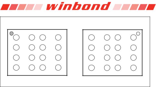
3.6Ball Configuration TFBGA 8x6-mm (5x5 or 6x4 Ball Array)
|
Top View |
|
|
Top View |
|
|||
|
|
|
|
|
A1 |
A2 |
A3 |
A4 |
|
A2 |
A3 |
A4 |
A5 |
NC |
NC |
NC |
NC |
|
NC |
NC |
NC |
NC |
B1 |
B2 |
B3 |
B4 |
|
|
|
|
|
||||
B1 |
B2 |
B3 |
B4 |
B5 |
NC |
CLK |
GND |
VCC |
NC |
CLK |
GND |
VCC |
NC |
C1 |
C2 |
C3 |
C4 |
|
|
|
|
|
||||
C1 |
C2 |
C3 |
C4 |
C5 |
NC |
/CS |
NC |
/WP (IO2) |
NC |
/CS |
NC |
/WP (IO2) |
NC |
D1 |
D2 |
D3 |
D4 |
|
|
|
|
|
||||
D1 |
D2 |
D3 |
D4 |
D5 |
NC |
DO(IO1) |
DI(IO0) |
/HOLD(IO3) |
|
|
|
|
|
|
|
|
/RESET |
NC |
DO(IO1) |
DI(IO0) |
/HOLD(IO3) |
NC |
E1 |
E2 |
E3 |
E4 |
|
|
|
/RESET |
|
||||
|
|
|
|
|
|
|
|
|
E1 |
E2 |
E3 |
E4 |
E5 |
NC |
NC |
NC |
NC |
NC |
NC |
NC |
NC |
NC |
F1 |
F2 |
F3 |
F4 |
|
|
|
|
|
||||
|
|
|
|
|
NC |
NC |
NC |
NC |
|
Package Code TB |
|
Package Code TC |
|||||
Figure 1d. W25Q64FW Ball Assignments, 24-ball TFBGA 8x6-mm (Package Code TB, TC)
3.7Ball Description TFBGA 8x6-mm
BALL NO. |
PIN NAME |
I/O |
FUNCTION |
|
|
|
|
B2 |
CLK |
I |
Serial Clock Input |
|
|
|
|
B3 |
GND |
|
Ground |
|
|
|
|
B4 |
VCC |
|
Power Supply |
|
|
|
|
C2 |
/CS |
I |
Chip Select Input |
|
|
|
|
C4 |
/WP (IO2) |
I/O |
Write Protect Input (Data Input Output 2)(2) |
D2 |
DO (IO1) |
I/O |
Data Output (Data Input Output 1)(1) |
D3 |
DI (IO0) |
I/O |
Data Input (Data Input Output 0)(1) |
D4 |
/HOLD or /RESET |
I/O |
Hold or Reset Input (Data Input Output 3)(2) |
|
(IO3) |
|
|
|
|
|
|
Multiple |
NC |
|
No Connect |
|
|
|
|
|
|
|
|
Notes:
1.IO0 and IO1 are used for Standard and Dual SPI instructions
2.IO0 –IO3 are used for Quad SPI instructions, /WP & /HOLD (or /RESET) functions are only available for Standard/Dual SPI.
|
Publication Release Date: March 25, 2013 |
- 8 - |
Preliminary - Revision D |
W25Q64FW
3.8Ball Configuration WLBGA
Top View |
Bottom View |
A1 |
A2 |
A3 |
A4 |
NC |
VCC |
/CS |
NC |
B1 |
B2 |
B3 |
B4 |
NC |
/HOLD(IO3) DO(IO1) |
NC |
|
C1 |
C2 |
C3 |
C4 |
NC |
CLK |
/WP(IO2) |
NC |
D1 |
D2 |
D3 |
D4 |
NC |
DI(IO0) |
GND |
NC |
A4 |
A3 |
A2 |
A1 |
NC |
/CS |
VCC |
NC |
B4 |
B3 |
B2 |
B1 |
NC |
DO(IO1) /HOLD(IO3) |
NC |
|
C4 |
C3 |
C2 |
C1 |
NC |
/WP(IO2) |
CLK |
NC |
D4 |
D3 |
D2 |
D1 |
NC |
GND |
DI(IO0) |
NC |
Figure 1e. W25Q64FW Ball Assignments, 16-ball WLBGA (Package Code BY)
3.9Ball Description WLBGA
BALL NO. |
PIN NAME |
I/O |
FUNCTION |
|
|
|
|
A2 |
VCC |
|
Power Supply |
|
|
|
|
B2 |
/HOLD or /RESET |
I/O |
Hold or Reset Input (Data Input Output 3)(2) |
|
(IO3) |
|
|
C2 |
CLK |
I |
Serial Clock Input |
|
|
|
|
D2 |
DI (IO0) |
I/O |
Data Input (Data Input Output 0)(1) |
A3 |
/CS |
I |
Chip Select Input |
|
|
|
|
B3 |
DO (IO1) |
I/O |
Data Output (Data Input Output 1)(1) |
C3 |
/WP (IO2) |
I/O |
Write Protect Input (Data Input Output 2)(2) |
D3 |
GND |
|
Ground |
|
|
|
|
Multiple |
NC |
|
No Connect |
|
|
|
|
|
|
|
|
Notes:
1.IO0 and IO1 are used for Standard and Dual SPI instructions
2.IO0 –IO3 are used for Quad SPI instructions, /WP & /HOLD (or /RESET) functions are only available for Standard/Dual SPI.
- 9 -
W25Q64FW
4.PIN DESCRIPTIONS
4.1 Chip Select (/CS)
The SPI Chip Select (/CS) pin enables and disables device operation. When /CS is high the device is deselected and the Serial Data Output (DO, or IO0, IO1, IO2, IO3) pins are at high impedance. When deselected, the devices power consumption will be at standby levels unless an internal erase, program or write status register cycle is in progress. When /CS is brought low the device will be selected, power consumption will increase to active levels and instructions can be written to and data read from the device. After power-up, /CS must transition from high to low before a new instruction will be accepted. The /CS
input must track the VCC supply level at power-up and power-down (see “Write Protection 57). If needed a pull-up resister on the /CS pin can be used to accomplish this.
4.2 Serial Data Input, Output and IOs (DI, DO and IO0, IO1, IO2, IO3)
The W25Q64FW supports standard SPI, Dual SPI and Quad SPI operation. Standard SPI instructions use the unidirectional DI (input) pin to serially write instructions, addresses or data to the device on the rising edge of the Serial Clock (CLK) input pin. Standard SPI also uses the unidirectional DO (output) to read data or status from the device on the falling edge of CLK.
Dual and Quad SPI instructions use the bidirectional IO pins to serially write instructions, addresses or data to the device on the rising edge of CLK and read data or status from the device on the falling edge of CLK. Quad SPI instructions require the non-volatile Quad Enable bit (QE) in Status Register-2 to be set. When QE=1, the /WP pin becomes IO2 and /HOLD pin becomes IO3.
4.3 Write Protect (/WP)
The Write Protect (/WP) pin can be used to prevent the Status Register from being written. Used in conjunction with the StatusSEC,Register’sTB, BP2, BP1 and BP0)Blockbits and StatusProtect (
Register Protect (SRP) bits, a portion as small as a 4KB sector or the entire memory array can be hardware protected. The /WP pin is active low. When the QE bit of Status Register-2 is set for Quad I/O, the /WP pin function is not available since this pin is used for IO2. See Figure 1a-c for the pin configuration of Quad I/O operation.
4.4 HOLD (/HOLD)
The /HOLD pin allows the device to be paused while it is actively selected. When /HOLD is brought low, while /CS is low, the DO pin will be at high impedance and signals on the DI and CLK pins will be ignored
(don’t care). When /HOLD is brought /HOLDhigh,functiondevicecan be oper useful when multiple devices are sharing the same SPI signals. The /HOLD pin is active low. When the
QE bit of Status Register-2 is set for Quad I/O, the /HOLD pin function is not available since this pin is used for IO3. See Figure 1a-c for the pin configuration of Quad I/O operation.
4.5 Serial Clock (CLK)
The SPI Serial Clock Input (CLK) pin provides the timing for serial input and output operations. ("See SPI Operations")
4.6Reset (/RESET)
The /RESET pin allows the device to be reset by the controller. For 8-pin packages, when QE=0, the IO3 pin can be configured either as a /HOLD pin or as a /RESET pin depending on Status Register setting. When QE=1, the /HOLD or /RESET function is not available for 8-pin configuration. On the 16-pin SOIC package, a dedicated /RESET pin is provided and it is independent of QE bit setting.
|
Publication Release Date: March 25, 2013 |
- 10 - |
Preliminary - Revision D |
W25Q64FW
5. BLOCK DIAGRAM
|
|
|
|
Security Register 3 - 0 |
|
|||
|
|
|
|
003000h |
|
0030FFh |
|
|
|
|
|
|
002000h |
|
0020FFh |
|
|
|
|
|
|
001000h |
|
0010FFh |
|
|
Block Segmentation |
|
000000h |
|
0000FFh |
|
|||
|
|
|
|
|
||||
xxFF00h |
|
xxFFFFh |
|
7FFF00h |
|
7FFFFFh |
|
|
• |
Sector 15 (4KB) |
• |
|
|
|
|||
|
• |
Block 127 (64KB) |
• |
|
||||
xxF000h |
|
xxF0FFh |
|
|
||||
|
|
7F0000h |
|
7F00FFh |
|
|||
xxEF00h |
|
xxEFFFh |
|
|
|
|||
|
|
|
|
|
|
|||
• |
Sector 14 (4KB) |
• |
|
|
|
|
|
|
xxE000h |
|
xxE0FFh |
|
|
|
|
|
|
xxDF00h |
|
xxDFFFh |
|
|
|
|
|
|
• |
Sector 13 (4KB) |
• |
|
|
|
|
|
|
xxD000h |
|
xxD0FFh |
|
|
|
|
|
|
|
|
|
|
|
• |
|
|
|
|
• |
|
|
|
• |
|
|
|
|
• |
|
|
|
• |
|
|
|
|
• |
|
Decode |
|
|
|
|
|
xx2F00h |
|
xx2FFFh |
|
|
|
|
||
|
Row |
|
|
|
|
|||
• |
Sector 2 (4KB) |
• |
|
|
|
|
||
xx2000h |
|
xx20FFh |
|
|
|
|
||
|
Protect Logic and |
|
|
|
|
|||
xx1F00h |
|
xx1FFFh |
40FF00h |
|
40FFFFh |
W25Q64FW |
||
• |
Sector 1 (4KB) |
• |
|
|||||
• |
Block 64 (64KB) |
• |
||||||
xx1000h |
|
xx10FFh |
||||||
|
400000h |
|
4000FFh |
|||||
xx0F00h |
|
xx0FFFh |
|
|||||
|
|
|
|
|||||
• |
Sector 0 (4KB) |
• |
3FFF00h |
|
3FFFFFh |
|||
xx0000h |
|
xx00FFh |
• |
Block 63 (64KB) |
• |
|||
|
|
|
||||||
|
|
|
3F0000h |
|
3F00FFh |
|||
|
|
|
Write |
|
|
|||
|
|
|
|
• |
|
|
||
|
Write Control |
|
|
|
• |
|
|
|
/WP (IO2) |
|
|
|
• |
|
|
||
Logic |
|
|
|
|
|
|||
|
|
|
|
|
|
|
||
|
|
|
|
20FF00h |
|
20FFFFh |
|
|
|
|
|
|
• |
Block 32 (64KB) |
• |
|
|
|
|
|
|
200000h |
|
2000FFh |
|
|
|
Status |
|
|
1FFF00h |
|
1FFFFFh |
|
|
|
|
|
|
|
|
|||
|
Register |
|
|
• |
Block 31 (64KB) |
• |
|
|
|
|
|
|
|
||||
|
|
|
|
1F0000h |
|
1F00FFh |
|
|
|
|
|
|
|
• |
|
|
|
|
|
High Voltage |
|
|
• |
|
|
|
|
|
|
|
• |
|
|
||
|
|
Generators |
|
|
|
|
||
|
|
|
|
|
|
|
||
|
|
|
|
00FF00h |
|
00FFFFh |
|
|
/HOLD (IO3) |
|
|
|
• |
Block 0 (64KB) |
• |
|
|
or /RESET (IO3) |
|
|
|
000000h |
|
0000FFh |
|
|
CLK |
|
Page Address |
|
|
|
|
|
|
|
Latch / Counter |
|
Beginning |
|
Ending |
|
||
|
SPI |
|
|
|
||||
|
|
|
Page Address |
|
Page Address |
|
||
/CS |
Command & |
|
|
|
|
|||
|
|
|
|
|
|
|||
|
Control Logic |
|
|
|
Column Decode |
|
|
|
|
|
|
|
|
|
|
||
|
|
|
|
And 256-Byte Page Buffer |
|
|||
|
|
Data |
|
|
|
|
|
|
DI (IO0) |
|
|
|
|
|
|
|
|
DO (IO1) |
|
Byte Address |
|
|
|
|
|
|
|
|
Latch / Counter |
|
|
|
|
|
|
Figure 2. W25Q64FW Serial Flash Memory Block Diagram
- 11 -
W25Q64FW
6.FUNCTIONAL DESCRIPTIONS
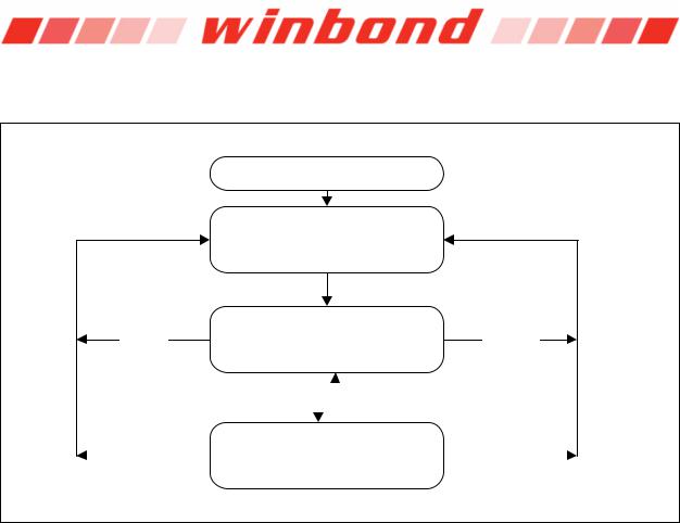
6.1 SPI / QPI Operations
Power Up
Device Initialization
& Status Register Refresh
(Non-Volatile Cells)
Standard SPI
Hardware Dual SPI
Reset
Quad SPI
SPI Reset (66h + 99h)
|
|
|
Enable QPI (38h) |
|
|
|
Disable QPI (FFh) |
|||
|
|
|
|
|
|
|||||
|
|
|
|
|
|
|
|
|
|
|
|
|
|
|
|
|
|
|
|
|
|
|
|
|
|
|
|
|
|
|
|
|
|
Hardware |
|
QPI |
|
|
QPI Reset |
|
|||
|
Reset |
|
|
|
|
(66h + 99h) |
|
|||
|
|
|
|
|
|
|
|
|||
Figure 3. W25Q64FW Serial Flash Memory Operation Diagram
6.1.1Standard SPI Instructions
The W25Q64FW is accessed through an SPI compatible bus consisting of four signals: Serial Clock (CLK), Chip Select (/CS), Serial Data Input (DI) and Serial Data Output (DO). Standard SPI instructions use the DI input pin to serially write instructions, addresses or data to the device on the rising edge of CLK. The DO output pin is used to read data or status from the device on the falling edge of CLK.
SPI bus operation Mode 0 (0,0) and 3 (1,1) are supported. The primary difference between Mode 0 and Mode 3 concerns the normal state of the CLK signal when the SPI bus master is in standby and data is not being transferred to the Serial Flash. For Mode 0, the CLK signal is normally low on the falling and rising edges of /CS. For Mode 3, the CLK signal is normally high on the falling and rising edges of /CS.
6.1.2Dual SPI Instructions
The W25Q64FW supports Dual SPI operation when using instructions such as “Fast Read Dual Output (3Bh)”and “Fast DualReadI/O (BBh)”. These instructions allow data to be transferred to or from the device at two to three times the rate of ordinary Serial Flash devices. The Dual SPI Read instructions are ideal for quickly downloading code to RAM upon power-up (code-shadowing) or for executing non-speed- critical code directly from the SPI bus (XIP). When using Dual SPI instructions, the DI and DO pins become bidirectional I/O pins: IO0 and IO1.
|
Publication Release Date: March 25, 2013 |
- 12 - |
Preliminary - Revision D |

W25Q64FW
6.1.3Quad SPI Instructions
The W25Q64FW supports Quad SPI operation when using instructions such as “Fast Read Quad Output (6Bh)”,Fast“Read Quad I/O (EBh)”, “Word Read(E7h)”Quand I/O“ctal Word Read
(E3h)”. These instructions allow data to be transferred to or from the device four to six times the rate of ordinary Serial Flash. The Quad Read instructions offer a significant improvement in continuous and random access transfer rates allowing fast code-shadowing to RAM or execution directly from the SPI bus (XIP). When using Quad SPI instructions the DI and DO pins become bidirectional IO0 and IO1, and the /WP and /HOLD pins become IO2 and IO3 respectively. Quad SPI instructions require the nonvolatile Quad Enable bit (QE) in Status Register-2 to be set.
6.1.4QPI Instructions
The W25Q64FW supports Quad Peripheral Interface (QPI) operations only when the device is switched
from Standard/Dual/Quad SPI mode to QPI modeEnterusingQPI (38h)”the “instructionThe typical SPI . protocol requires that the byte-long instruction code being shifted into the device only via DI pin in eight
serial clocks. The QPI mode utilizes all four IO pins to input the instruction code, thus only two serial clocks are required. This can significantly reduce the SPI instruction overhead and improve system performance in an XIP environment. Standard/Dual/Quad SPI mode and QPI mode are exclusive. Only
one mode can be activeEnter QPIat(38h)”any ExitgivenandQPI (FFh)”“time.instructions“ a switch between these two modes. Upon power-up or after a software instruction,reset using the default state of the device is Standard/Dual/Quad SPI mode. To enable QPI mode, the non-volatile
Quad Enable bit (QE) in Status Register-2 is required to be set. When using QPI instructions, the DI and DO pins become bidirectional IO0 and IO1, and the /WP and /HOLD pins become IO2 and IO3 respectively. See Figure 3 for the device operation modes.
6.1.5Hold Function
For Standard SPI and Dual SPI operations, the /HOLD signal allows the W25Q64FW operation to be paused while it is actively selected (when /CS is low). The /HOLD function may be useful in cases where the SPI data and clock signals are shared with other devices. For example, consider if the page buffer was only partially written when a priority interrupt requires use of the SPI bus. In this case the /HOLD function can save the state of the instruction and the data in the buffer so programming can resume where it left off once the bus is available again. The /HOLD function is only available for standard SPI and Dual SPI operation, not during Quad SPI or QPI. The Quad Enable Bit QE in Status Register-2 is used to determine if the pin is used as /HOLD pin or data I/O pin. When QE=0 (factory default), the pin is /HOLD, when QE=1, the pin will become an I/O pin, /HOLD function is no longer available.
To initiate a /HOLD condition, the device must be selected with /CS low. A /HOLD condition will activate on the falling edge of the /HOLD signal if the CLK signal is already low. If the CLK is not already low the /HOLD condition will activate after the next falling edge of CLK. The /HOLD condition will terminate on the rising edge of the /HOLD signal if the CLK signal is already low. If the CLK is not already low the /HOLD condition will terminate after the next falling edge of CLK. During a /HOLD condition, the Serial Data Output (DO) is high impedance, and Serial Data Input (DI) and Serial Clock (CLK) are ignored. The Chip Select (/CS) signal should be kept active (low) for the full duration of the /HOLD operation to avoid resetting the internal logic state of the device.
- 13 -

W25Q64FW
6.1.6Software Reset & Hardware /RESET pin
The W25Q64FW can be reset to the initial power-on state by a software Reset sequence, either in SPI mode or QPI mode. This sequence must include two consecutive commands: Enable Reset (66h) & Reset (99h). If the command sequence is successfully accepted, the device will take approximately 30uS (tRST) to reset. No command will be accepted during the reset period.
For the 8-pin and TFBGA package types, W25Q64FW can also be configured to utilize a hardware /RESET pin. The HOLD/RST bit in the Status Register-3 is the configuration bit for /HOLD pin function or RESET pin function. When HOLD/RST=0 (factory default), the pin acts as a /HOLD pin as described above; when HOLD/RST=1, the pin acts as a /RESET pin. Drive the /RESET pin low for a minimum period of ~1us (tRESET*) will reset the device to its initial power-on state. Any on-going Program/Erase operation will be interrupted and data corruption may happen. While /RESET is low, the device will not accept any command input.
If QE bit is set to 1 on the 8-pin packages, the /HOLD or /RESET function will be disabled, the pin will become one of the four data I/O pins.
For the SOIC-16 package, W25Q64FW provides a dedicated /RESET pin in addition to the /HOLD (IO3) pin as illustrated in Figure 1b. Drive the /RESET pin low for a minimum period of ~1us (tRESET*) will reset the device to its initial power-on state. The HOLD/RST bit or QE bit in the Status Register will not affect the function of this dedicated /RESET pin.
Hardware /RESET pin has the highest priority among all the input signals. Drive /RESET low for a minimum period of ~1us (tRESET*) will interrupt any on-going external/internal operations, regardless the status of other SPI signals (/CS, CLK, IOs, /WP and/or /HOLD).
Note:
1.While a faster /RESET pulse (as short as a few hundred nanoseconds) will often reset the device, a 1us minimum is recommended to ensure reliable operation.
2.There is an internal pull-up resistor for the dedicated /RESET pin on the SOIC-16 package. If the reset function is not needed, this pin can be left floating in the system.
|
Publication Release Date: March 25, 2013 |
- 14 - |
Preliminary - Revision D |

W25Q64FW
6.2Write Protection
Applications that use non-volatile memory must take into consideration the possibility of noise and other adverse system conditions that may compromise data integrity. To address this concern, the W25Q64FW provides several means to protect the data from inadvertent writes.
6.2.1Write Protect Features
Device resets when VCC is below threshold
Time delay write disable after Power-up
Write enable/disable instructions and automatic write disable after erase or program
Software and Hardware (/WP pin) write protection using Status Registers
Additional Individual Block/Sector Locks for array protection
Write Protection using Power-down instruction
Lock Down write protection for Status Register until the next power-up
One Time Program (OTP) write protection for array and Security Registers using Status Register*
*Note: This feature is available upon special order. Please contact Winbond for details.
Upon power-up or at power-down, the W25Q64FW will maintain a reset condition while VCC is below the threshold value of VWI, (See Power-up Timing and Voltage Levels and Figure 57). While reset, all operations are disabled and no instructions are recognized. During power-up and after the VCC voltage exceeds VWI, all program and erase related instructions are further disabled for a time delay of tPUW. This includes the Write Enable, Page Program, Sector Erase, Block Erase, Chip Erase and the Write Status Register instructions. Note that the chip select pin (/CS) must track the VCC supply level at power-up until the VCC-min level and tVSL time delay is reached, and it must also track the VCC supply level at powerdown to prevent adverse command sequence. If needed a pull-up resister on /CS can be used to accomplish this.
After power-up the device is automatically placed in a write-disabled state with the Status Register Write Enable Latch (WEL) set to a 0. A Write Enable instruction must be issued before a Page Program, Sector Erase, Block Erase, Chip Erase or Write Status Register instruction will be accepted. After completing a program, erase or write instruction the Write Enable Latch (WEL) is automatically cleared to a writedisabled state of 0.
Software controlled write protection is facilitated using the Write Status Register instruction and setting the Status Register Protect (SRP0, SRP1) and Block Protect (CMP, SEC, TB, BP[2:0]) bits. These settings allow a portion or the entire memory array to be configured as read only. Used in conjunction with the Write Protect (/WP) pin, changes to the Status Register can be enabled or disabled under hardware control. See Status Register section for further information. Additionally, the Power-down instruction offers an extra level of write protection as all instructions are ignored except for the Release Power-down instruction.
The W25Q64FW also provides another Write Protect method using the Individual Block Locks. Each 64KB block (except the top and bottom blocks, total of 510 blocks) and each 4KB sector within the top/bottom blocks (total of 32 sectors) are equipped with an Individual Block Lock bit. When the lock bit is 0, the corresponding sector or block can be erased or programmed; when the lock bit is set to 1, Erase or Program commands issued to the corresponding sector or block will be ignored. When the device is powered on, all Individual Block Lock bits will be 1, so the entire memory array is protected from
Erase/Program. An “Individualock(39h)”instruction mustBlockbe issued toUnlunlock any specific sector or block.
The WPS bit in Status Register-3 is used to decide which Write Protect scheme should be used. When WPS=0 (factory default), the device will only utilize CMP, SEC, TB, BP[2:0] bits to protect specific areas of the array; when WPS=1, the device will utilize the Individual Block Locks for write protection.
- 15 -

W25Q64FW
7.STATUS AND CONFIGURATION REGISTERS
Three Status and Configuration Registers are provided for W25Q64FW. The Read Status Register-1/2/3 instructions can be used to provide status on the availability of the flash memory array, whether the device is write enabled or disabled, the state of write protection, Quad SPI setting, Security Register lock status, Erase/Program Suspend status, output driver strength, power-up and current Address Mode. The Write Status Register instruction can be used to configure the device write protection features, Quad SPI setting, Security Register OTP locks, Hold/Reset functions, output driver strength and power-up Address Mode. Write access to the Status Register is controlled by the state of the non-volatile Status Register Protect bits (SRP0, SRP1), the Write Enable instruction, and during Standard/Dual SPI operations, the /WP pin.
7.1 Status Registers
|
|
|
S7 |
S6 |
S5 |
S4 |
S3 |
S2 |
S1 |
S0 |
||||||||
|
|
|
|
|
|
|
|
|
|
|
|
|
|
|
|
|
|
|
|
|
|
SRP0 |
SEC |
TB |
BP2 |
BP1 |
BP0 |
WEL |
BUSY |
||||||||
|
|
|
|
|
|
|
|
|
|
|
|
|
|
|
|
|
|
|
|
Status Register Protect 0 |
|
|
|
|
|
|
|
|
|
|
|
|
|
|
|
|
|
|
(Volatile/Non-Volatile Writable) |
|
|
|
|
|
|
|
|
|
|
|
|
|
|
|
||
|
|
|
|
|
|
|
|
|
|
|
|
|
|
|
|
|
||
|
Sector Protect Bit |
|
|
|
|
|
|
|
|
|
|
|
|
|
|
|||
|
(Volatile/Non-Volatile Writable) |
|
|
|
|
|
|
|
|
|
|
|
|
|
|
|
||
|
|
|
|
|
|
|
|
|
|
|
|
|
|
|
|
|
|
|
|
Top/Bottom Protect Bit |
|
|
|
|
|
|
|
|
|
|
|
|
|
|
|
||
|
(Volatile/Non-Volatile Writable) |
|
|
|
|
|
|
|
|
|
|
|
|
|
|
|
||
|
|
|
|
|
|
|
|
|
|
|
|
|
|
|
|
|
||
|
Block Protect Bits |
|
|
|
|
|
|
|
|
|
|
|
|
|
|
|||
|
(Volatile/Non-Volatile Writable) |
|
|
|
|
|
|
|
|
|
|
|
|
|
|
|
||
|
|
|
|
|
|
|
|
|
|
|
|
|
|
|
|
|||
|
Write Enable Latch |
|
|
|
|
|
|
|
|
|
|
|
|
|
|
|
||
|
(Status-Only) |
|
|
|
|
|
|
|
|
|
|
|
|
|
|
|
||
|
|
|
|
|
|
|
|
|
|
|
|
|
|
|
|
|||
|
Erase/Write In Progress |
|
|
|
|
|
|
|
|
|
|
|
|
|
|
|
||
|
(Status-Only) |
|
|
|
|
|
|
|
|
|
|
|
|
|
|
|
||
Figure 4a. Status Register-1
7.1.1Erase/Write In Progress (BUSY) – Status Only
BUSY is a read only bit in the status register (S0) that is set to a 1 state when the device is executing a Page Program, Quad Page Program, Sector Erase, Block Erase, Chip Erase, Write Status Register or Erase/Program Security Register instruction. During this time the device will ignore further instructions except for the Read Status Register and Erase/Program Suspend instruction (see tW, tPP, tSE, tBE, and tCE in AC Characteristics). When the program, erase or write status/security register instruction has completed, the BUSY bit will be cleared to a 0 state indicating the device is ready for further instructions.
7.1.2Write Enable Latch (WEL) – Status Only
Write Enable Latch (WEL) is a read only bit in the status register (S1) that is set to 1 after executing a Write Enable Instruction. The WEL status bit is cleared to 0 when the device is write disabled. A write disable state occurs upon power-up or after any of the following instructions: Write Disable, Page Program, Quad Page Program, Sector Erase, Block Erase, Chip Erase, Write Status Register, Erase Security Register and Program Security Register.
7.1.3Block Protect Bits (BP2, BP1, BP0) – Volatile/Non-Volatile Writable
The Block Protect Bits (BP2, BP1, BP0) are non-volatile read/write bits in the status register (S4, S3, and S2) that provide Write Protection control and status. Block Protect bits can be set using the Write Status Register Instruction (see tW in AC characteristics). All, none or a portion of the memory array can be
|
Publication Release Date: March 25, 2013 |
- 16 - |
Preliminary - Revision D |

W25Q64FW
protected from Program and Erase instructions (see Status Register Memory Protection table). The factory default setting for the Block Protection Bits is 0, none of the array protected.
7.1.4Top/Bottom Block Protect (TB) – Volatile/Non-Volatile Writable
The non-volatile Top/Bottom bit (TB) controls if the Block Protect Bits (BP2, BP1, BP0) protect from the Top (TB=0) or the Bottom (TB=1) of the array as shown in the Status Register Memory Protection table. The factory default setting is TB=0. The TB bit can be set with the Write Status Register Instruction depending on the state of the SRP0, SRP1 and WEL bits.
7.1.5 Sector/Block Protect Bit (SEC) – Volatile/Non-Volatile Writable
The non-volatile Sector/Block Protect bit (SEC) controls if the Block Protect Bits (BP2, BP1, BP0) protect either 4KB Sectors (SEC=1) or 64KB Blocks (SEC=0) in the Top (TB=0) or the Bottom (TB=1) of the array as shown in the Status Register Memory Protection table. The default setting is SEC=0.
7.1.6Complement Protect (CMP) – Volatile/Non-Volatile Writable
The Complement Protect bit (CMP) is a non-volatile read/write bit in the status register (S14). It is used in conjunction with SEC, TB, BP2, BP1 and BP0 bits to provide more flexibility for the array protection. Once CMP is set to 1, previous array protection set by SEC, TB, BP2, BP1 and BP0 will be reversed. For instance, when CMP=0, a top 64KB block can be protected while the rest of the array is not; when CMP=1, the top 64KB block will become unprotected while the rest of the array become read-only. Please refer to the Status Register Memory Protection table for details. The default setting is CMP=0.
7.1.7Status Register Protect (SRP1, SRP0) – Volatile/Non-Volatile Writable
The Status Register Protect bits (SRP1 and SRP0) are non-volatile read/write bits in the status register (S8 and S7). The SRP bits control the method of write protection: software protection, hardware protection, power supply lock-down or one time programmable (OTP) protection.
SRP1 |
SRP0 |
/WP |
Status |
Description |
|
Register |
|||||
|
|
|
|
||
|
|
|
|
|
|
0 |
0 |
X |
Software |
/WP pin has no control. The Status register can be written to |
|
Protection |
after a Write Enable instruction, WEL=1. [Factory Default] |
||||
|
|
|
|||
|
|
|
|
|
|
0 |
1 |
0 |
Hardware |
When /WP pin is low the Status Register locked and cannot |
|
Protected |
be written to. |
||||
|
|
|
|||
|
|
|
|
|
|
0 |
1 |
1 |
Hardware |
When /WP pin is high the Status register is unlocked and can |
|
Unprotected |
be written to after a Write Enable instruction, WEL=1. |
||||
|
|
|
|||
|
|
|
|
|
|
1 |
0 |
X |
Power Supply |
Status Register is protected and cannot be written to again |
|
Lock-Down |
until the next power-down, power-up cycle.(1) |
||||
|
|
|
|
|
|
1 |
1 |
X |
One Time |
Status Register is permanently protected and cannot be |
|
Program(2) |
written to. |
||||
|
|
|
|
|
|
|
|
|
|
|
Notes:
1.When SRP1, SRP0 = (1, 0), a power-down, power-up cycle will change SRP1, SRP0 to (0, 0) state.
2.This feature is available upon special order. Please contact Winbond for details.
- 17 -

W25Q64FW
|
|
|
S15 |
S14 |
S13 |
S12 |
S11 |
S10 |
S9 |
S8 |
||||||||
|
|
|
|
|
|
|
|
|
|
|
|
|
|
|
|
|
|
|
|
|
|
SUS |
CMP |
LB3 |
LB2 |
LB1 |
LB0 |
QE |
SRP1 |
||||||||
|
|
|
|
|
|
|
|
|
|
|
|
|
|
|
|
|
|
|
|
Suspend Status |
|
|
|
|
|
|
|
|
|
|
|
|
|
|
|
|
|
|
(Status-Only) |
|
|
|
|
|
|
|
|
|
|
|
|
|
|
|
||
|
|
|
|
|
|
|
|
|
|
|
|
|
|
|
|
|
|
|
|
Complement Protect |
|
|
|
|
|
|
|
|
|
|
|
|
|
|
|
||
|
(Volatile/Non-Volatile Writable) |
|
|
|
|
|
|
|
|
|
|
|
|
|
|
|
||
|
|
|
|
|
|
|
|
|
|
|
|
|
|
|
|
|
||
|
Security Register Lock Bits |
|
|
|
|
|
|
|
|
|
|
|
|
|
|
|||
(Volatile/Non-Volatile OTP Writable) |
|
|
|
|
|
|
|
|
|
|
|
|
|
|
|
|||
|
|
|
|
|
|
|
|
|
|
|
|
|
|
|
|
|
||
|
Quad Enable |
|
|
|
|
|
|
|
|
|
|
|
|
|
|
|||
|
(Volatile/Non-Volatile Writable) |
|
|
|
|
|
|
|
|
|
|
|
|
|
|
|
||
|
|
|
|
|
|
|
|
|
|
|
|
|
|
|
|
|
||
|
Status Register Protect 1 |
|
|
|
|
|
|
|
|
|
|
|
|
|
|
|||
|
(Volatile/Non-Volatile Writable) |
|
|
|
|
|
|
|
|
|
|
|
|
|
|
|
||
Figure 4b. Status Register-2
7.1.8Erase/Program Suspend Status (SUS) – Status Only
The Suspend Status bit is a read only bit in the status register (S15) that is set to 1 after executing a Erase/Program Suspend (75h) instruction. The SUS status bit is cleared to 0 by Erase/Program Resume (7Ah) instruction as well as a power-down, power-up cycle.
7.1.9Security Register Lock Bits (LB3, LB2, LB1, LB0) – Volatile/Non-Volatile OTP Writable
The Security Register Lock Bits (LB3, LB2, LB1, LB0) are non-volatile One Time Program (OTP) bits in Status Register (S13, S12, S11, S10) that provide the write protect control and status to the Security Registers. The default state of LB3-0 is 0, Security Registers are unlocked. LB3-0 can be set to 1 individually using the Write Status Register instruction. LB3-0 are One Time Programmable (OTP), once it’s setcorrespondingto 1,256the-Byte Security Register will become read-only permanently.
7.1.10Quad Enable (QE) – Volatile/Non-Volatile Writable
The Quad Enable (QE) bit is a non-volatile read/write bit in the status register (S9) that allows Quad SPI and QPI operation. When the QE bit is set to a 0 state (factory default), the /WP pin and /HOLD are enabled. When the QE bit is set to a 1, the Quad IO2 and IO3 pins are enabled, and /WP and /HOLD functions are disabled.
QE bit is required to be set to a 1 before issuingEnter anQPI (38h)”“ to switch the Standard/Dual/Quad SPI to QPI, otherwise the command will be ignored. When the device is in QPI
mode, QE bit will remain to be 1. A “Write Status Regi from a “1” to a “0”.
WARNING: If the /WP or /HOLD pins are tied directly to the power supply or ground during standard SPI or Dual SPI operation, the QE bit should never be set to a 1.
|
Publication Release Date: March 25, 2013 |
- 18 - |
Preliminary - Revision D |

W25Q64FW
|
|
|
|
S23 |
S22 |
S21 |
S20 |
S19 |
S18 |
S17 |
S16 |
|||||||
|
|
|
|
|
|
|
|
|
|
|
|
|
|
|
|
|
|
|
|
|
|
|
HOLD |
DRV1 |
DRV0 |
(R) |
(R) |
WPS |
(R) |
(R) |
|||||||
|
|
|
|
/RST |
||||||||||||||
|
|
|
|
|
|
|
|
|
|
|
|
|
|
|
|
|
||
|
|
|
|
|
|
|
|
|
|
|
|
|
|
|
|
|
|
|
|
/HOLD or /RESET Function |
|
|
|
|
|
|
|
|
|
|
|
|
|
|
|
|
|
|
(Volatile/Non-Volatile Writable) |
|
|
|
|
|
|
|
|
|
|
|
|
|
|
|||
|
|
|
|
|
|
|
|
|
|
|
|
|
|
|
|
|
|
|
|
Output Driver Strength |
|
|
|
|
|
|
|
|
|
|
|
|
|
|
|||
|
(Volatile/Non-Volatile Writable) |
|
|
|
|
|
|
|
|
|
|
|
|
|
|
|||
|
|
|
|
|
|
|
|
|
|
|
|
|
|
|
|
|
|
|
|
Reserved |
|
|
|
|
|
|
|
|
|
|
|
|
|
|
|
|
|
|
|
|
|
|
|
|
|
|
|
|
|
|
|
|
||||
|
|
|
|
|
|
|
|
|
|
|
|
|
|
|
|
|||
|
|
|
|
|
|
|
|
|
|
|
|
|
|
|
|
|||
|
Write Protect Selection |
|
|
|
|
|
|
|
|
|
|
|
|
|
||||
|
(Volatile/Non-Volatile Writable) |
|
|
|
|
|
|
|
|
|
|
|
|
|
|
|
|
|
|
|
|
|
|
|
|
|
|
|
|
|
|
|
|
|
|
|
|
|
Reserved |
|
|
|
|
|
|
|
|
|
|
|
|
|
|
|
|
|
|
|
|
|
|
|
|
|
|
|
|
|
|
|
|
||||
|
|
|
|
|
|
|
|
|
|
|
|
|
|
|
|
|
|
|
Figure 4c. Status Register-3
7.1.11 Write Protect Selection (WPS) – Volatile/Non-Volatile Writable
The WPS bit is used to select which Write Protect scheme should be used. When WPS=0, the device will use the combination of CMP, SEC, TB, BP[2:0] bits to protect a specific area of the memory array. When WPS=1, the device will utilize the Individual Block Locks to protect any individual sector or blocks. The default value for all Individual Block Lock bits is 1 upon device power on or after reset.
7.1.12 Output Driver Strength (DRV1, DRV0) – Volatile/Non-Volatile Writable
The DRV1 & DRV0 bits are used to determine the output driver strength for the Read operations.
DRV1, DRV0 |
Driver Strength |
|
|
0, 0 |
100% |
|
|
0, 1 |
75% |
|
|
1, 0 |
50% |
|
|
1, 1 |
25% (default) |
|
|
7.1.13 /HOLD or /RESET Pin Function (HOLD/RST) – Volatile/Non-Volatile Writable
The HOLD/RST bit is used to determine whether /HOLD or /RESET function should be implemented on the hardware pin for 8-pin packages. When HOLD/RST=0 (factory default), the pin acts as /HOLD; when HOLD/RST=1, the pin acts as /RESET. However, /HOLD or /RESET functions are only available when QE=0. If QE is set to 1, the /HOLD and /RESET functions are disabled, the pin acts as a dedicated data I/O pin.
7.1.14 Reserved Bits – Non Functional
There are a few reserved Status Register bits that may ignore the values of those bits. During a “Write Stat written as “0”, but there will not be any effects.
- 19 -
W25Q64FW
7.1.15W25Q64FW Status Register Memory Protection (WPS = 0, CMP = 0)
|
STATUS REGISTER(1) |
|
W25Q64FW (64M-BIT) MEMORY PROTECTION(3) |
||||||||
SEC |
|
TB |
BP2 |
BP1 |
|
BP0 |
PROTECTED |
PROTECTED |
PROTECTED |
PROTECTED |
|
|
|
BLOCK(S) |
ADDRESSES |
DENSITY |
PORTION(2) |
||||||
X |
|
X |
0 |
0 |
|
0 |
NONE |
NONE |
NONE |
NONE |
|
|
|
|
|
|
|
|
|
|
|
|
|
0 |
|
0 |
0 |
0 |
|
1 |
126 and 127 |
7E0000h –7FFFFFh |
128KB |
Upper 1/64 |
|
|
|
|
|
|
|
|
|
|
|
|
|
0 |
|
0 |
0 |
1 |
|
0 |
124 thru 127 |
7C0000h –7FFFFFh |
256KB |
Upper 1/32 |
|
|
|
|
|
|
|
|
|
|
|
|
|
0 |
|
0 |
0 |
1 |
|
1 |
120 thru 127 |
780000h –7FFFFFh |
512KB |
Upper 1/16 |
|
|
|
|
|
|
|
|
|
|
|
|
|
0 |
|
0 |
1 |
0 |
|
0 |
112 thru 127 |
700000h –7FFFFFh |
1MB |
Upper 1/8 |
|
|
|
|
|
|
|
|
|
|
|
|
|
0 |
|
0 |
1 |
0 |
|
1 |
96 thru 127 |
600000h –7FFFFFh |
2MB |
Upper 1/4 |
|
|
|
|
|
|
|
|
|
|
|
|
|
0 |
|
0 |
1 |
1 |
|
0 |
64 thru 127 |
400000h –7FFFFFh |
4MB |
Upper 1/2 |
|
|
|
|
|
|
|
|
|
|
|
|
|
0 |
|
1 |
0 |
0 |
|
1 |
0 and 1 |
000000h |
–01FFFFh |
128KB |
Lower 1/64 |
|
|
|
|
|
|
|
|
|
|
|
|
0 |
|
1 |
0 |
1 |
|
0 |
0 thru 3 |
000000h |
–03FFFFh |
256KB |
Lower 1/32 |
|
|
|
|
|
|
|
|
|
|
|
|
0 |
|
1 |
0 |
1 |
|
1 |
0 thru 7 |
000000h |
–07FFFFh |
512KB |
Lower 1/16 |
|
|
|
|
|
|
|
|
|
|
|
|
0 |
|
1 |
1 |
0 |
|
0 |
0 thru 15 |
000000h –0FFFFFh |
1MB |
Lower 1/8 |
|
|
|
|
|
|
|
|
|
|
|
|
|
0 |
|
1 |
1 |
0 |
|
1 |
0 thru 31 |
000000h –1FFFFFh |
2MB |
Lower 1/4 |
|
|
|
|
|
|
|
|
|
|
|
|
|
0 |
|
1 |
1 |
1 |
|
0 |
0 thru 63 |
000000h –3FFFFFh |
4MB |
Lower 1/2 |
|
|
|
|
|
|
|
|
|
|
|
|
|
X |
|
X |
1 |
1 |
|
1 |
0 thru 127 |
000000h –7FFFFFh |
8MB |
ALL |
|
|
|
|
|
|
|
|
|
|
|
|
|
1 |
|
0 |
0 |
0 |
|
1 |
127 |
7FF000h –7FFFFFh |
4KB |
U –1/2048 |
|
|
|
|
|
|
|
|
|
|
|
|
|
1 |
|
0 |
0 |
1 |
|
0 |
127 |
7FE000h –7FFFFFh |
8KB |
U –1/1024 |
|
|
|
|
|
|
|
|
|
|
|
|
|
1 |
|
0 |
0 |
1 |
|
1 |
127 |
7FC000h –7FFFFFh |
16KB |
U –1/512 |
|
|
|
|
|
|
|
|
|
|
|
|
|
1 |
|
0 |
1 |
0 |
|
X |
127 |
7F8000h –7FFFFFh |
32KB |
U –1/256 |
|
|
|
|
|
|
|
|
|
|
|
|
|
1 |
|
1 |
0 |
0 |
|
1 |
0 |
000000h –000FFFh |
4KB |
L –1/2048 |
|
|
|
|
|
|
|
|
|
|
|
|
|
1 |
|
1 |
0 |
1 |
|
0 |
0 |
000000h –001FFFh |
8KB |
L –1/1024 |
|
|
|
|
|
|
|
|
|
|
|
|
|
1 |
|
1 |
0 |
1 |
|
1 |
0 |
000000h –003FFFh |
16KB |
L –1/512 |
|
|
|
|
|
|
|
|
|
|
|
|
|
1 |
|
1 |
1 |
0 |
|
X |
0 |
000000h –007FFFh |
32KB |
L –1/256 |
|
|
|
|
|
|
|
|
|
|
|
|
|
|
|
|
|
|
|
|
|
|
|
|
|
Notes:
1.X = don’t care
2.L = Lower; U = Upper
3.If any Erase or Program command specifies a memory region that contains protected data portion, this command will be ignored.
|
Publication Release Date: March 25, 2013 |
- 20 - |
Preliminary - Revision D |

W25Q64FW
7.1.16W25Q64FW Status Register Memory Protection (WPS = 0, CMP = 1)
|
STATUS REGISTER(1) |
|
W25Q64FW (64M-BIT) MEMORY PROTECTION(3) |
|||||||
SEC |
|
TB |
BP2 |
BP1 |
|
BP0 |
PROTECTED |
PROTECTED |
PROTECTED |
PROTECTED |
|
|
BLOCK(S) |
ADDRESSES |
DENSITY |
PORTION(2) |
|||||
X |
|
X |
0 |
0 |
|
0 |
0 thru 127 |
000000h –7FFFFFh |
8MB |
ALL |
|
|
|
|
|
|
|
|
|
|
|
0 |
|
0 |
0 |
0 |
|
1 |
0 thru 125 |
000000h –7DFFFFh |
8,064KB |
Lower 63/64 |
|
|
|
|
|
|
|
|
|
|
|
0 |
|
0 |
0 |
1 |
|
0 |
0 thru 123 |
000000h –7BFFFFh |
7,936KB |
Lower 31/32 |
|
|
|
|
|
|
|
|
|
|
|
0 |
|
0 |
0 |
1 |
|
1 |
0 thru 119 |
000000h –77FFFFh |
7,680KB |
Lower 15/16 |
|
|
|
|
|
|
|
|
|
|
|
0 |
|
0 |
1 |
0 |
|
0 |
0 thru 111 |
000000h –6FFFFFh |
7MB |
Lower 7/8 |
|
|
|
|
|
|
|
|
|
|
|
0 |
|
0 |
1 |
0 |
|
1 |
0 thru 95 |
000000h –5FFFFFh |
5MB |
Lower 3/4 |
|
|
|
|
|
|
|
|
|
|
|
0 |
|
0 |
1 |
1 |
|
0 |
0 thru 63 |
000000h –3FFFFFh |
4MB |
Lower 1/2 |
|
|
|
|
|
|
|
|
|
|
|
0 |
|
1 |
0 |
0 |
|
1 |
2 thru 127 |
020000h –7FFFFFh |
8,064KB |
Upper 63/64 |
|
|
|
|
|
|
|
|
|
|
|
0 |
|
1 |
0 |
1 |
|
0 |
4 thru 127 |
040000h –7FFFFFh |
7,936KB |
Upper 31/32 |
|
|
|
|
|
|
|
|
|
|
|
0 |
|
1 |
0 |
1 |
|
1 |
8 thru 127 |
080000h –7FFFFFh |
7,680KB |
Upper 15/16 |
|
|
|
|
|
|
|
|
|
|
|
0 |
|
1 |
1 |
0 |
|
0 |
16 thru 127 |
100000h –7FFFFFh |
7MB |
Upper 7/8 |
|
|
|
|
|
|
|
|
|
|
|
0 |
|
1 |
1 |
0 |
|
1 |
32 thru 127 |
200000h –7FFFFFh |
5MB |
Upper 3/4 |
|
|
|
|
|
|
|
|
|
|
|
0 |
|
1 |
1 |
1 |
|
0 |
64 thru 127 |
400000h –7FFFFFh |
4MB |
Upper 1/2 |
|
|
|
|
|
|
|
|
|
|
|
X |
|
X |
1 |
1 |
|
1 |
NONE |
NONE |
NONE |
NONE |
|
|
|
|
|
|
|
|
|
|
|
1 |
|
0 |
0 |
0 |
|
1 |
0 thru 127 |
000000h –7FEFFFh |
8,188KB |
L –2047/2048 |
|
|
|
|
|
|
|
|
|
|
|
1 |
|
0 |
0 |
1 |
|
0 |
0 thru 127 |
000000h –7FDFFFh |
8,184KB |
L –1023/1024 |
|
|
|
|
|
|
|
|
|
|
|
1 |
|
0 |
0 |
1 |
|
1 |
0 thru 127 |
000000h –7FBFFFh |
8,176KB |
L –511/512 |
|
|
|
|
|
|
|
|
|
|
|
1 |
|
0 |
1 |
0 |
|
X |
0 thru 127 |
000000h –7F7FFFh |
8,160KB |
L –255/256 |
|
|
|
|
|
|
|
|
|
|
|
1 |
|
1 |
0 |
0 |
|
1 |
0 thru 127 |
001000h –7FFFFFh |
8,188KB |
L –2047/2048 |
|
|
|
|
|
|
|
|
|
|
|
1 |
|
1 |
0 |
1 |
|
0 |
0 thru 127 |
002000h –7FFFFFh |
8,184KB |
L –1023/1024 |
|
|
|
|
|
|
|
|
|
|
|
1 |
|
1 |
0 |
1 |
|
1 |
0 thru 127 |
004000h –7FFFFFh |
8,176KB |
L –511/512 |
|
|
|
|
|
|
|
|
|
|
|
1 |
|
1 |
1 |
0 |
|
X |
0 thru 127 |
008000h –7FFFFFh |
8,160KB |
L –255/256 |
|
|
|
|
|
|
|
|
|
|
|
|
|
|
|
|
|
|
|
|
|
|
Notes:
1.X = don’t care
2.L = Lower; U = Upper
3.If any Erase or Program command specifies a memory region that contains protected data portion, this command will be ignored.
-21 -

W25Q64FW
7.1.17W25Q64FW Individual Block Memory Protection (WPS=1)
Block 127 (64KB)
Block 0 (64KB)
Notes:
Sector 15 (4KB) |
|
|
|
|
|
|
|
|
|
||
Sector 14 (4KB) |
|
|
|
|
|
|
|
|
|
||
|
|
|
|
|
|
Sector 1 (4KB) |
|
|
|
Individual Block Locks: |
|
|
|
|
|||
Sector 0 (4KB) |
|
|
|
||
|
|
|
32 Sectors (Top/Bottom) |
||
|
|
|
|
||
|
|
|
|
126 Blocks |
|
Block 126 (64KB) |
|
|
|
Individual Block Lock: |
|
|
|
||||
|
|
|
|
36h + Address |
|
|
|
|
|
Individual Block Unlock: |
|
|
|
|
|
||
|
|
|
|
39h + Address |
|
|
|
|
|
||
|
|
|
|
Read Block Lock: |
|
|
|
|
|
||
|
|
|
|
||
|
|
|
|
3Dh + Address |
|
Block 1 (64KB) |
|
|
|
Global Block Lock: |
|
|
|
||||
|
|
|
|
7Eh |
|
|
|
|
|
Global Block Unlock: |
|
Sector 15 (4KB) |
|||||
|
|
|
98h |
||
Sector 14 (4KB) |
|
|
|
||
|
|
|
|
||
|
|
|
|
|
|
Sector 1 (4KB) |
|
|
|
|
|
|
|
|
|
||
Sector 0 (4KB) |
|
|
|
|
|
|
|
|
|
Figure 4d. Individual Block/Sector Locks
1.Individual Block/Sector protection is only valid when WPS=1.
2.All individual block/sector lock bits are set to 1 by default after power up, all memory array is protected.
|
Publication Release Date: March 25, 2013 |
- 22 - |
Preliminary - Revision D |

W25Q64FW
8. INSTRUCTIONS
The Standard/Dual/Quad SPI instruction set of the W25Q64FW consists of 45 basic instructions that are fully controlled through the SPI bus (see Instruction Set Table1-2). Instructions are initiated with the falling edge of Chip Select (/CS). The first byte of data clocked into the DI input provides the instruction code. Data on the DI input is sampled on the rising edge of clock with most significant bit (MSB) first.
The QPI instruction set of the W25Q64FW consists of 32 basic instructions that are fully controlled through the SPI bus (see Instruction Set Table 3). Instructions are initiated with the falling edge of Chip Select (/CS). The first byte of data clocked through IO[3:0] pins provides the instruction code. Data on all four IO pins are sampled on the rising edge of clock with most significant bit (MSB) first. All QPI instructions, addresses, data and dummy bytes are using all four IO pins to transfer every byte of data with every two serial clocks (CLK).
Instructions vary in length from a single byte to several bytes and may be followed by address bytes, data
bytes, dummy bytes (don’t care), and in some cases, a combinat rising edge of edge /CS. Clock relative timing diagrams for each instruction are included in Figures 5
through 57. All read instructions can be completed after any clocked bit. However, all instructions that Write, Program or Erase must complete on a byte boundary (/CS driven high after a full 8-bits have been clocked) otherwise the instruction will be ignored. This feature further protects the device from inadvertent writes. Additionally, while the memory is being programmed or erased, or when the Status Register is being written, all instructions except for Read Status Register will be ignored until the program or erase cycle has completed.
8.1Device ID and Instruction Set Tables
8.1.1Manufacturer and Device Identification
MANUFACTURER ID |
(MF7 - MF0) |
|
|
|
|
Winbond Serial Flash |
EFh |
|
|
|
|
|
|
|
Device ID |
(ID7 - ID0) |
(ID15 - ID0) |
|
|
|
Instruction |
ABh, 90h, 92h, 94h |
9Fh |
|
|
|
W25Q64FW |
16h |
6017h |
|
|
|
|
|
|
- 23 -

W25Q64FW
8.1.2Instruction Set Table 1 (Standard/Dual/Quad SPI Instructions)(1)
Data Input Output |
Byte 1 |
Byte 2 |
Byte 3 |
Byte 4 |
Byte 5 |
Byte 6 |
Byte 7 |
Clock Number |
(0 – 7) |
(8 – 15) |
(16 – 23) |
(24 – 31) |
(32 – 39) |
(40 – 47) |
(48 – 55) |
Write Enable |
06h |
|
|
|
|
|
|
Volatile SR Write Enable |
50h |
|
|
|
|
|
|
Write Disable |
04h |
|
|
|
|
|
|
Read Status Register-1 |
05h |
(S7-S0)(2) |
|
|
|
|
|
Write Status Register-1(4) |
01h |
(S7-S0)(4) |
|
|
|
|
|
Read Status Register-2 |
35h |
(S15-S8)(2) |
|
|
|
|
|
Write Status Register-2 |
31h |
(S15-S8) |
|
|
|
|
|
Read Status Register-3 |
15h |
(S23-S16)(2) |
|
|
|
|
|
Write Status Register-3 |
11h |
(S23-S16) |
|
|
|
|
|
Chip Erase |
C7h/60h |
|
|
|
|
|
|
Erase / Program Suspend |
75h |
|
|
|
|
|
|
Erase / Program Resume |
7Ah |
|
|
|
|
|
|
Power-down |
B9h |
|
|
|
|
|
|
|
|
|
|
|
|
|
|
Release Power-down / ID |
ABh |
Dummy |
Dummy |
Dummy |
(ID7-ID0)(2) |
|
|
Manufacturer/Device ID |
90h |
Dummy |
Dummy |
00h |
(MF7-MF0) |
(ID7-ID0) |
|
JEDEC ID |
9Fh |
(MF7-MF0) |
(ID15-ID8) |
(ID7-ID0) |
|
|
|
|
|
|
|
|
|
|
|
Global Block Lock |
7Eh |
|
|
|
|
|
|
|
|
|
|
|
|
|
|
Global Block Unlock |
98h |
|
|
|
|
|
|
|
|
|
|
|
|
|
|
Enter QPI Mode |
38h |
|
|
|
|
|
|
Enable Reset |
66h |
|
|
|
|
|
|
Reset Device |
99h |
|
|
|
|
|
|
|
|
|
|
|
|
|
|
|
|
|
|
|
|
|
|
|
Publication Release Date: March 25, 2013 |
- 24 - |
Preliminary - Revision D |

W25Q64FW
8.1.3Instruction Set Table 2 (Standard/Dual/Quad SPI Instructions)(1)
Data Input Output |
Byte 1 |
Byte 2 |
|
|
|
Byte 3 |
|
|
Byte 4 |
|
Byte 5 |
|
|
|
Byte 6 |
|||||||
Clock Number |
(0 – 7) |
(8 – 15) |
|
|
|
(16 – 23) |
|
|
(24 – 31) |
(32 – 39) |
|
|
(40 – 47) |
|||||||||
Read Unique ID |
4Bh |
Dummy |
|
|
|
Dummy |
|
|
Dummy |
|
Dummy |
|
(UID63-UID0) |
|||||||||
Page Program |
02h |
A23-A16 |
|
A15-A8 |
|
|
A7-A0 |
|
D7-D0 |
|
|
|
D7-D0(3) |
|||||||||
Quad Page Program |
32h |
A23-A16 |
|
A15-A8 |
|
|
A7-A0 |
D7-D0, …(9) |
|
D7-D0, …(3) |
||||||||||||
Sector Erase (4KB) |
20h |
A23-A16 |
|
A15-A8 |
|
|
A7-A0 |
|
|
|
|
|
|
|
|
|
||||||
Block Erase (32KB) |
52h |
A23-A16 |
|
A15-A8 |
|
|
A7-A0 |
|
|
|
|
|
|
|
|
|
||||||
Block Erase (64KB) |
D8h |
A23-A16 |
|
A15-A8 |
|
|
A7-A0 |
|
|
|
|
|
|
|
|
|
||||||
Read Data |
03h |
A23-A16 |
|
A15-A8 |
|
|
A7-A0 |
|
(D7-D0) |
|
|
|
|
|||||||||
Fast Read |
0Bh |
A23-A16 |
|
A15-A8 |
|
|
A7-A0 |
|
Dummy |
|
|
|
(D7-D0) |
|||||||||
Fast Read Dual Output |
3Bh |
A23-A16 |
|
A15-A8 |
|
|
A7-A0 |
|
Dummy |
|
(D7-D0, …)(7) |
|||||||||||
Fast Read Quad Output |
6Bh |
A23-A16 |
|
A15-A8 |
|
|
A7-A0 |
|
Dummy |
|
(D7-D0, …)(9) |
|||||||||||
Erase Security Register(5) |
44h |
A23-A16 |
|
A15-A8 |
|
|
A7-A0 |
|
|
|
|
|
|
|
|
|
||||||
Program Security Register(5) |
42h |
A23-A16 |
|
A15-A8 |
|
|
A7-A0 |
|
D7-D0 |
|
|
|
D7-D0(3) |
|||||||||
Read Security Register(5) |
48h |
A23-A16 |
|
A15-A8 |
|
|
A7-A0 |
|
Dummy |
|
|
|
(D7-D0) |
|||||||||
Individual Block Lock |
36h |
A23-A16 |
|
A15-A8 |
|
|
A7-A0 |
|
|
|
|
|
|
|
|
|
||||||
|
|
|
|
|
|
|
|
|
|
|
|
|
|
|
|
|
|
|
|
|
|
|
Individual Block Unlock |
39h |
A23-A16 |
|
A15-A8 |
|
|
A7-A0 |
|
|
|
|
|
|
|
|
|
||||||
Read Block Lock |
3Dh |
A23-A16 |
|
A15-A8 |
|
|
A7-A0 |
|
(L7-L0) |
|
|
|
|
|||||||||
Data Input Output |
Byte 1 |
Byte 2 |
|
|
Byte 3 |
|
Byte 4 |
|
|
Byte 5 |
|
|
|
Byte 6 |
|
|
Byte 7 |
|||||
Clock Number |
(0 – 7) |
(8 – 11) |
|
(12 – 15) |
|
(16 – 19) |
|
|
(20 – 23) |
|
|
|
(24 – 27) |
|
|
(28 – 31) |
||||||
Fast Read Dual I/O |
BBh |
A23-A16 |
|
A15-A8 |
|
A7-A0 |
|
|
Dummy |
|
|
(D7-D0) |
|
|
|
|||||||
Mftr./Device ID Dual I/O |
92h |
A23-A16 |
|
A15-A8 |
|
A7-A0 |
|
|
Dummy |
|
(MF7-MF0) |
|
|
(ID7-ID0) |
||||||||
|
|
|
|
|
|
|
|
|
|
|
|
|
|
|
|
|
|
|
|
|||
Data Input Output |
Byte 1 |
Byte 2 |
|
Byte 3 |
|
Byte 4 |
Byte 5 |
|
|
Byte 6 |
Byte 7 |
|
Byte 8 |
|
|
Byte 9 |
||||||
Clock Number |
(0 – 7) |
(8, 9) |
|
(10, 11) |
|
(12, 13) |
(14, 15) |
|
(16, 17) |
(18, 19) |
|
(20, 21) |
|
|
(22, 23) |
|||||||
Set Burst with Wrap |
77h |
Dummy |
|
Dummy |
|
Dummy |
W8-W0 |
|
|
|
|
|
|
|
|
|
|
|
|
|||
Fast Read Quad I/O |
EBh |
A23-A16 |
|
A15-A8 |
|
A7-A0 |
M7-M0 |
|
Dummy |
Dummy |
|
(D7-D0) |
|
|
(D7-D0) |
|||||||
Word Read Quad I/O(12) |
E7h |
A23-A16 |
|
A15-A8 |
|
A7-A0 |
M7-M0 |
|
Dummy |
(D7-D0) |
|
(D7-D0) |
|
|
(D7-D0) |
|||||||
Octal Word Read Quad I/O(13) |
E3h |
A23-A16 |
|
A15-A8 |
|
A7-A0 |
M7-M0 |
|
(D7-D0) |
(D7-D0) |
|
(D7-D0) |
|
|
(D7-D0) |
|||||||
Mftr./Device ID Quad I/O |
94h |
A23-A16 |
|
A15-A8 |
|
A7-A0 |
M7-M0 |
|
Dummy |
Dummy |
|
(MF7-MF0) |
|
|
(ID7-ID0) |
|||||||
|
|
|
|
|
|
|
|
|
|
|
|
|
|
|
|
|
|
|
|
|
|
|
|
|
|
|
|
|
|
|
|
|
|
|
|
|
|
|
|
|
|
|
|
|
|
- 25 -

W25Q64FW
8.1.4Instruction Set Table 3 (QPI Instructions)(14)
Data Input Output |
Byte 1 |
Byte 2 |
Byte 3 |
Byte 4 |
Byte 5 |
Byte 6 |
Clock Number |
(0, 1) |
(2, 3) |
(4, 5) |
(6, 7) |
(8, 9) |
(10, 11) |
Write Enable |
06h |
|
|
|
|
|
Volatile SR Write Enable |
50h |
|
|
|
|
|
Write Disable |
04h |
|
|
|
|
|
Read Status Register-1 |
05h |
(S7-S0)(2) |
|
|
|
|
Write Status Register-1(4) |
01h |
(S7-S0)(4) |
|
|
|
|
Read Status Register-2 |
35h |
(S15-S8)(2) |
|
|
|
|
Write Status Register-2 |
31h |
(S15-S8) |
|
|
|
|
Read Status Register-3 |
15h |
(S23-S16)(2) |
|
|
|
|
Write Status Register-3 |
11h |
(S23-S16) |
|
|
|
|
Chip Erase |
C7h/60h |
|
|
|
|
|
Erase / Program Suspend |
75h |
|
|
|
|
|
Erase / Program Resume |
7Ah |
|
|
|
|
|
Power-down |
B9h |
|
|
|
|
|
|
|
|
|
|
|
|
Set Read Parameters |
C0h |
P7-P0 |
|
|
|
|
Release Powerdown / ID |
ABh |
Dummy |
Dummy |
Dummy |
(ID7-ID0)(2) |
|
Manufacturer/Device ID |
90h |
Dummy |
Dummy |
00h |
(MF7-MF0) |
(ID7-ID0) |
|
|
|
|
|
|
|
JEDEC ID |
9Fh |
(MF7-MF0) |
(ID15-ID8) |
(ID7-ID0) |
|
|
|
|
|
|
|
|
|
Global Block Lock |
7Eh |
|
|
|
|
|
|
|
|
|
|
|
|
Global Block Unlock |
98h |
|
|
|
|
|
Exit QPI Mode |
FFh |
|
|
|
|
|
Enable Reset |
66h |
|
|
|
|
|
Reset Device |
99h |
|
|
|
|
|
|
|
|
|
|
|
|
Page Program |
02h |
A23-A16 |
A15-A8 |
A7-A0 |
D7-D0(9) |
D7-D0(3) |
Sector Erase (4KB) |
20h |
A23-A16 |
A15-A8 |
A7-A0 |
|
|
Block Erase (32KB) |
52h |
A23-A16 |
A15-A8 |
A7-A0 |
|
|
Block Erase (64KB) |
D8h |
A23-A16 |
A15-A8 |
A7-A0 |
|
|
Fast Read |
0Bh |
A23-A16 |
A15-A8 |
A7-A0 |
Dummy(15) |
(D7-D0) |
Burst Read with Wrap(16) |
0Ch |
A23-A16 |
A15-A8 |
A7-A0 |
Dummy(15) |
(D7-D0) |
Fast Read Quad I/O |
EBh |
A23-A16 |
A15-A8 |
A7-A0 |
M7-M0(15) |
(D7-D0) |
Individual Block Lock |
36h |
A23-A16 |
A15-A8 |
A7-A0 |
|
|
|
|
|
|
|
|
|
Individual Block Unlock |
39h |
A23-A16 |
A15-A8 |
A7-A0 |
|
|
Read Block Lock |
3Dh |
A23-A16 |
A15-A8 |
A7-A0 |
(L7-L0) |
|
|
|
|
|
|
|
|
|
Publication Release Date: March 25, 2013 |
- 26 - |
Preliminary - Revision D |

W25Q64FW
Notes:
1.Data bytes are shifted with Most Significant)” indicateBitta firstda . output from the device on either 1, 2 or 4 IO pins.
2.The Status Register contents and Device ID will repeat continuously until /CS terminates the instruction.
3.At least one byte of data input is required for Page Program, Quad Page Program and Program Security Registers, up to 256 bytes of data input. If more than 256 bytes of data are sent to the device, the addressing will wrap to the beginning of the page and overwrite previously sent data.
4.Write Status Register-1 (01h) can also be used to program Status Register-1&2, see section 8.2.5.
5.Security Register Address:
Security Register 0: |
A23-16 = 00h; |
A15-8 = 00h; |
A7-0 = byte address |
Security Register 1: |
A23-16 = 00h; |
A15-8 = 10h; |
A7-0 = byte address |
Security Register 2: |
A23-16 = 00h; |
A15-8 = 20h; |
A7-0 = byte address |
Security Register 3: |
A23-16 = 00h; |
A15-8 = 30h; |
A7-0 = byte address |
6. Dual SPI address input format: |
|
IO0 = A22, A20, A18, A16, A14, A12, A10, A8 |
A6, A4, A2, A0, M6, M4, M2, M0 |
IO1 = A23, A21, A19, A17, A15, A13, A11, A9 |
A7, A5, A3, A1, M7, M5, M3, M1 |
7.Dual SPI data output format:
IO0 = (D6, D4, D2, D0)
IO1 = (D7, D5, D3, D1)
8. Quad SPI address input format: |
|
IO0 = A20, A16, A12, A8, |
A4, A0, M4, M0 |
IO1 = A21, A17, A13, A9, |
A5, A1, M5, M1 |
IO2 = A22, A18, A14, A10, A6, A2, M6, M2
IO3 = A23, A19, A15, A11, A7, A3, M7, M3
9.Quad SPI data input/output format:
IO0 = (D4, D0, …..)
IO1 = (D5, D1, …..)
IO2 = (D6, D2, …..)
IO3 = (D7, D3, …..)
10. Fast Read Quad I/O data output format: IO0 = (x, x, x, x, D4, D0, D4, D0) IO1 = (x, x, x, x, D5, D1, D5, D1) IO2 = (x, x, x, x, D6, D2, D6, D2) IO3 = (x, x, x, x, D7, D3, D7, D3)
11. Word Read Quad I/O data output format:
IO0 = (x, x, D4, D0, D4, D0, D4, D0) IO1 = (x, x, D5, D1, D5, D1, D5, D1) IO2 = (x, x, D6, D2, D6, D2, D6, D2) IO3 = (x, x, D7, D3, D7, D3, D7, D3)
Set Burst with Wrap input format: IO0 = x, x, x, x, x, x, W4, x IO1 = x, x, x, x, x, x, W5, x IO2 = x, x, x, x, x, x, W6, x IO3 = x, x, x, x, x, x, x, x
12.For Word Read Quad I/O, the lowest address bit must be 0. (A0 = 0)
13.For Octal Word Read Quad I/O, the lowest four address bits must be 0. (A3, A2, A1, A0 = 0)
14.QPI Command, Address, Data input/output format:
CLK # 0 1 |
2 |
3 |
4 |
5 |
6 7 |
8 9 |
10 11 |
IO0 = C4, C0, |
A20, A16, |
A12, A8, |
A4, A0, |
D4, D0, |
D4, D0 |
||
IO1 = C5, C1, |
A21, A17, |
A13, A9, |
A5, A1, |
D5, D1, |
D5, D1 |
||
IO2 = C6, C2, |
A22, A18, |
A14, A10, |
A6, A2, |
D6, D2, |
D6, D2 |
||
IO3 = C7, C3, |
A23, A19, |
A15, A11, |
A7, A3, |
D7, D3, |
D7, D3 |
||
15.The number of dummy clocks for QPI Fast Read, QPI Fast Read Quad I/O & QPI Burst Read with Wrap is controlled by read parameter P7 –P4.
16.The wrap around length for QPI Burst Read with Wrap is controlled by read parameter P3 –P0.
-27 -

W25Q64FW
8.2Instruction Descriptions
8.2.1Write Enable (06h)
The Write Enable instruction (Figure 5) sets the Write Enable Latch (WEL) bit in the Status Register to a 1. The WEL bit must be set prior to every Page Program, Quad Page Program, Sector Erase, Block Erase, Chip Erase, Write Status Register and Erase/Program Security Registers instruction. The Write
Enable instruction is entered by driving /CS low, shifting the instruction code pin on the rising edge of CLK, and then driving /CS high.
|
|
|
|
|
|
|
|
|
|
|
|
|
|
|
|
|
|
|
|
|
|
|
|
|
|
|
|
|
|
|
|
/CS |
|
|
|
|
|
|
|
|
|
|
|
|
|
|
|
|
|
|
|
|
|
|
|
|
|
|
|
|
|
|
|
|
|
|
|
|
|
|
|
|
|
|
|
|
|
|
|
|
|
|
|
|
|
|
|
|
|
|
|
/CS |
|
|
|
|
|
|
|
|
|
|
|
|
|
|
|
|
|
|
|
|
|
|
|
|
|
|
|
|
|
|
|
|
Mode 3 |
0 1 |
|
|
|
Mode 3 |
|||||||
|
|
|
|
|
|
|
|
|
|
|
|
|
|
|
|
|
|
|
|
|
|
|
|
|
|
|
|
|
|
|
|
|
|
|
|||||||||||
|
|
|
|
|
|
|
|
|
|
|
|
|
|
|
|
|
|
|
|
|
|
|
|
|
|
|
|
|
|
|
CLK |
Mode 0 |
|
|
|
|
|
|
|
|
|
|
Mode 0 |
||
|
|
|
|
|
|
|
|
|
|
|
|
|
|
|
|
|
|
|
|
|
|
|
|
|
|
|
|
|
|
|
|
|
|
|
|
|
|
|
|
|
|
||||
|
|
|
|
|
|
|
|
|
|
|
|
|
|
|
|
|
|
|
|
|
|
|
|
|
|
|
|
|
|
|
|
|
|
|
|
|
|
|
|
||||||
|
Mode 3 |
0 |
1 |
2 |
3 |
4 |
|
|
|
5 |
6 |
7 |
|
|
Mode 3 |
|
|
|
|
|
|
|
|
|
|
||||||||||||||||||||
CLK |
|
|
|
|
|
|
|
|
Instruction |
|
|
|
|
||||||||||||||||||||||||||||||||
|
|
|
|
|
|
|
|
|
|
|
|
|
|
|
|
|
|
|
|
|
|
|
|
|
|
|
|
|
|
|
|
|
|
|
|
|
|
||||||||
Mode 0 |
|
|
|
|
|
|
|
|
|
|
|
|
|
|
|
|
|
|
|
|
|
|
|
Mode 0 |
|
|
|
|
06h |
|
|
|
|||||||||||||
|
|
|
|
|
|
|
|
|
|
|
|
|
|
|
|
|
|
|
|
|
|
|
|
|
|
|
|
|
|||||||||||||||||
|
|
|
|
|
|
|
|
|
|
|
|
|
|
|
|
|
|
|
|
|
|
|
|
|
|
|
|
|
|
|
|
IO0 |
|
|
|
|
|
|
|
|
|
|
|
|
|
DI |
|
|
|
|
|
|
|
|
|
Instruction (06h) |
|
|
|
|
|
|
|
|
|
|
|
|
|
|
|
|
|
|
|
|
|
|
|
|
|
||||||||||
|
|
|
|
|
|
|
|
|
|
|
|
|
|
|
|
|
|
|
|
|
IO1 |
|
|
|
|
|
|
|
|
|
|
|
|
|
|||||||||||
|
|
|
|
|
|
|
|
|
|
|
|
|
|
|
|
|
|
|
|
|
|
|
|
|
|
|
|
|
|
|
|
|
|
||||||||||||
|
|
|
|
|
|
|
|
|
|
|
|
|
|
|
|
|
|
|
|
|
|
|
|
|
|
|
|
|
|
|
|
|
|
|
|
|
|
|
|
|
|
|
|
||
|
|
|
|
|
|
|
|
|
|
|
|
|
|
|
|
|
|
|
|
|
|
|
|
|
|
|
|
|
|
|
|
|
|
|
|
|
|
|
|
|
|
|
|
||
|
|
|
|
|
|
|
|
|
|
|
|
|
|
|
|
|
|
|
|
|
|
|
|
|
|
|
|
|
|
|
|
|
|
|
|
|
|
|
|
|
|
|
|
||
|
|
|
|
|
|
|
|
|
|
|
|
|
|
|
|
|
|
|
|
|
|
|
|
|
|
|
|
|
|
|
|
|
|
|
|
|
|
|
|
|
|
|
|
||
(IO0) |
|
|
|
|
|
|
|
|
|
|
|
|
|
|
|
|
|
|
|
|
|
|
|
|
|
|
|
|
|
|
|
|
|
|
|
|
|
|
|
|
|
|
|
|
|
|
|
|
|
|
|
|
|
|
High Impedance |
|
|
|
|
|
|
|
|
|
|
|
|
IO2 |
|
|
|
|
|
|
|
|
|
|
|
|
|
||||||||||
DO |
|
|
|
|
|
|
|
|
|
|
|
|
|
|
|
|
|
|
|
|
|
|
|
|
|
|
|
|
|
|
|
|
|
|
|||||||||||
|
|
|
|
|
|
|
|
|
|
|
|
|
|
|
|
|
|
|
|
|
|
|
|
|
|
|
|
|
|
|
|
|
|
||||||||||||
(IO1) |
|
|
|
|
|
|
|
|
|
|
|
|
|
|
|
|
|
|
|
|
|
|
|
|
|
|
|
|
|
|
|
IO3 |
|
|
|
|
|
|
|
|
|
|
|
|
|
|
|
|
|
|
|
|
|
|
|
|
|
|
|
|
|
|
|
|
|
|
|
|
|
|
|
|
|
|
|
|
|
|
|
|
|
|
|
|
|
|
|
|
|
||
|
|
|
|
|
|
|
|
|
|
|
|
|
|
|
|
|
|
|
|
|
|
|
|
|
|
|
|
|
|
|
|
|
|
|
|
|
|
|
|
|
|
|
|
|
|
Figure 5. Write Enable Instruction for SPI Mode (left) or QPI Mode (right)
8.2.2Write Enable for Volatile Status Register (50h)
The non-volatile Status Register bits described in section 7.1 can also be written to as volatile bits. This gives more flexibility to change the system configuration and memory protection schemes quickly without waiting for the typical non-volatile bit write cycles or affecting the endurance of the Status Register nonvolatile bits. To write the volatile values into the Status Register bits, the Write Enable for Volatile Status Register (50h) instruction must be issued prior to a Write Status Register (01h) instruction. Write Enable for Volatile Status Register instruction (Figure 6) will not set the Write Enable Latch (WEL) bit, it is only valid for the Write Status Register instruction to change the volatile Status Register bit values.
|
|
|
|
|
|
|
|
|
|
|
|
|
|
|
|
|
|
|
|
|
|
|
|
|
|
|
|
|
|
|
|
|
|
|
|
/CS |
|
|
|
|
|
|
|
|
|
|
|
|
|
|
|
|
|
|
|
|
|
|
|
|
|
|
|
|
|
|
|
|
|
|
|
|
|
|
|
|
|
|
|
|
|
|
|
|
|
|
|
|
|
|
|
|
|
|
|
|
|
|
|
|
|
|
|
/CS |
|
|
|
|
|
|
|
|
|
|
|
|
|
|
|
|
|
|
|
|
|
|
|
|
|
|
|
|
|
|
|
|
|
|
|
|
Mode 3 |
0 1 |
|
|
|
Mode 3 |
|||||||||
|
|
|
|
|
|
|
|
|
|
|
|
|
|
|
|
|
|
|
|
|
|
|
|
|
|
|
|
|
|
|
|
|
|
|
|
|
|
|
|||||||||||||
|
|
|
|
|
|
|
|
|
|
|
|
|
|
|
|
|
|
|
|
|
|
|
|
|
|
|
|
|
|
|
|
|
|
|
CLK |
Mode 0 |
|
|
|
|
|
|
|
|
|
|
|
|
Mode 0 |
||
|
|
|
|
|
|
|
|
|
|
|
|
|
|
|
|
|
|
|
|
|
|
|
|
|
|
|
|
|
|
|
|
|
|
|
|
|
|
|
|
|
|
|
|
|
|
|
|
||||
|
|
|
|
|
|
|
|
|
|
|
|
|
|
|
|
|
|
|
|
|
|
|
|
|
|
|
|
|
|
|
|
|
|
|
|
|
|
|
|
|
|
|
|
|
|
||||||
|
Mode 3 |
0 |
1 |
2 |
3 |
4 |
|
|
5 |
6 |
7 |
|
|
Mode 3 |
|
|
|
|
|
|
|
|
|
|
|
|
|||||||||||||||||||||||||
CLK |
|
|
|
|
|
|
|
Instruction |
|
|
|
|
|||||||||||||||||||||||||||||||||||||||
|
|
|
|
|
|
|
|
|
|
|
|
|
|
|
|
|
|
|
|
|
|
|
|
|
|
|
|
|
|
|
|
|
|
|
|
|
|
|
|
|
|
|
|||||||||
|
|
|
|
|
|
|
|
|
|
|
|
|
|
|
|
|
|
|
|
|
|
|
|
|
|
|
|
|
|
|
|
|
|
|
|
|
|
|
|
|
|
||||||||||
Mode 0 |
|
|
|
|
|
|
|
|
|
|
|
|
|
|
|
|
|
|
|
|
|
|
|
|
|
|
|
Mode 0 |
|
|
|
|
|
50h |
|
|
|
|
|||||||||||||
|
|
|
|
|
|
|
|
|
|
|
|
|
|
|
|
|
|
|
|
|
|
|
|
|
|
|
|
|
|
|
|
|
|
||||||||||||||||||
|
|
|
|
|
|
|
|
|
|
|
|
|
|
|
|
|
|
|
|
|
|
|
|
|
|
|
|
|
|
|
|
|
|
|
|
IO0 |
|
|
|
|
|
|
|
|
|
|
|
|
|
|
|
DI |
|
|
|
|
|
|
|
|
|
|
|
|
|
Instruction (50h) |
|
|
|
|
|
|
|
|
|
|
|
|
|
|
|
|
|
|
|
|
|
|
|
|
|
||||||||||||
|
|
|
|
|
|
|
|
|
|
|
|
|
|
|
|
|
|
|
|
|
|
|
IO1 |
|
|
|
|
|
|
|
|
|
|
|
|
|
|
|
|||||||||||||
|
|
|
|
|
|
|
|
|
|
|
|
|
|
|
|
|
|
|
|
|
|
|
|
|
|
|
|
|
|
|
|
|
|
|
|
|
|
||||||||||||||
|
|
|
|
|
|
|
|
|
|
|
|
|
|
|
|
|
|
|
|
|
|
|
|
|
|
|
|
|
|
|
|
|
|
|
|
|
|
|
|
|
|
|
|
|
|
|
|
|
|
||
|
|
|
|
|
|
|
|
|
|
|
|
|
|
|
|
|
|
|
|
|
|
|
|
|
|
|
|
|
|
|
|
|
|
|
|
|
|
|
|
|
|
|
|
|
|
|
|
|
|
||
|
|
|
|
|
|
|
|
|
|
|
|
|
|
|
|
|
|
|
|
|
|
|
|
|
|
|
|
|
|
|
|
|
|
|
|
|
|
|
|
|
|
|
|
|
|
|
|
|
|
||
|
|
|
|
|
|
|
|
|
|
|
|
|
|
|
|
|
|
|
|
|
|
|
|
|
|
|
|
|
|
|
|
|
|
|
|
|
|
|
|
|
|
|
|
|
|
|
|
|
|
||
(IO0) |
|
|
|
|
|
|
|
|
|
|
|
|
|
|
|
|
|
|
|
|
|
|
|
|
|
|
|
|
|
|
|
|
|
|
|
|
|
|
|
|
|
|
|
|
|
|
|
|
|
|
|
|
|
|
|
|
|
|
|
|
|
|
|
|
High Impedance |
|
|
|
|
|
|
|
|
|
|
IO2 |
|
|
|
|
|
|
|
|
|
|
|
|
|
|
|
||||||||||||
DO |
|
|
|
|
|
|
|
|
|
|
|
|
|
|
|
|
|
|
|
|
|
|
|
|
|
|
|
|
|
|
|
|
|
|
|
|
|
|
|||||||||||||
|
|
|
|
|
|
|
|
|
|
|
|
|
|
|
|
|
|
|
|
|
|
|
|
|
|
|
|
|
|
|
|
|
|
|
|
|
|
||||||||||||||
(IO1) |
|
|
|
|
|
|
|
|
|
|
|
|
|
|
|
|
|
|
|
|
|
|
|
|
|
|
|
|
|
|
|
|
|
|
|
IO3 |
|
|
|
|
|
|
|
|
|
|
|
|
|
|
|
|
|
|
|
|
|
|
|
|
|
|
|
|
|
|
|
|
|
|
|
|
|
|
|
|
|
|
|
|
|
|
|
|
|
|
|
|
|
|
|
|
|
|
|
|
|
|
|
|
|
||
|
|
|
|
|
|
|
|
|
|
|
|
|
|
|
|
|
|
|
|
|
|
|
|
|
|
|
|
|
|
|
|
|
|
|
|
|
|
|
|
|
|
|
|
|
|
|
|
|
|
|
|
Figure 6. Write Enable for Volatile Status Register Instruction for SPI Mode (left) or QPI Mode (right)
|
Publication Release Date: March 25, 2013 |
- 28 - |
Preliminary - Revision D |

W25Q64FW
8.2.3Write Disable (04h)
The Write Disable instruction (Figure 7) resets the Write Enable Latch (WEL) bit in the Status Register to
a 0. The Write Disable instruction is entered by driving /CS low, shifting the instruction code “04h” int DI pin and then driving /CS high. Note that the WEL bit is automatically reset after Power-up and upon
completion of the Write Status Register, Erase/Program Security Registers, Page Program, Quad Page Program, Sector Erase, Block Erase, Chip Erase and Reset instructions.
|
|
|
|
|
|
|
|
|
|
/CS |
|
|
|
|
|
|
|
|
|
|
|
|
|
|
|
Mode 3 |
0 |
1 |
Mode 3 |
/CS |
|
|
|
|
|
|
|
|
|
CLK |
Mode 0 |
|
|
Mode 0 |
|
|
|
|
|
|
|
|
|
|
|
|
|||
|
|
|
|
|
|
|
|
|
|
|
|
|
||
|
Mode 3 |
0 |
1 |
2 |
3 |
4 |
5 |
6 |
7 |
Mode 3 |
|
Instruction |
|
|
CLK |
Mode 0 |
|
|
|
|
|
|
|
|
Mode 0 |
|
04h |
|
|
|
|
|
|
|
|
|
|
|
|
|
|
|
||
|
|
|
|
Instruction (04h) |
|
|
|
IO0 |
|
|
|
|
||
|
|
|
|
|
|
|
|
|
|
|
|
|||
DI |
|
|
|
|
|
|
|
|
|
|
|
|
|
|
(IO ) |
|
|
|
|
|
|
|
|
|
IO1 |
|
|
|
|
0 |
|
|
|
|
|
|
|
|
|
|
|
|
|
|
DO |
|
|
|
High Impedance |
|
|
|
IO2 |
|
|
|
|
||
|
|
|
|
|
|
|
|
|
|
|
|
|
||
(IO1) |
|
|
|
|
|
|
|
|
|
|
|
|
|
|
|
|
|
|
|
|
|
|
|
|
IO3 |
|
|
|
|
Figure 7. Write Disable Instruction for SPI Mode (left) or QPI Mode (right)
8.2.4Read Status Register-1 (05h), Status Register-2 (35h) & Status Register-3 (15h)
The Read Status Register instructions allow the 8-bit Status Registers to be read. The instruction is entered by driving /CS low and shifting the instruction code “05h”for Status Register-1, “35h”for Status Register-2 or “15h” for -3Statusinto the DI pin onRegisterthe rising edge of CLK. The status register bits are then shifted out on the DO pin at the falling edge of CLK with most significant bit (MSB) first as shown in Figure 8. Refer to section 7.1 for Status Register descriptions.
The Read Status Register instruction may be used at any time, even while a Program, Erase or Write Status Register cycle is in progress. This allows the BUSY status bit to be checked to determine when the cycle is complete and if the device can accept another instruction. The Status Register can be read continuously, as shown in Figure 8. The instruction is completed by driving /CS high.
/CS |
|
|
|
|
|
|
|
|
|
|
|
|
|
|
|
|
|
|
|
|
|
|
|
|
|
|
|
Mode 3 |
0 |
1 |
2 |
3 |
4 |
5 |
6 |
7 |
8 |
9 |
10 |
11 |
12 |
13 |
14 |
15 |
16 |
17 |
18 |
19 |
20 |
21 |
22 |
23 |
|
CLK |
Mode 0 |
|
|
|
|
|
|
|
|
|
|
|
|
|
|
|
|
|
|
|
|
|
|
|
|
|
|
|
|
|
|
|
|
|
|
|
|
|
|
|
|
|
|
|
|
|
|
|
|
|
|
|
|
|
|
|
Instruction (05h/35h/15h) |
|
|
|
|
|
|
|
|
|
|
|
|
|
|
|
|
|
|
|
||||
DI |
|
|
|
|
|
|
|
|
|
|
|
|
|
|
|
|
|
|
|
|
|
|
|
|
|
|
(IO0) |
|
|
|
|
|
|
|
|
|
|
|
|
|
|
|
|
|
|
|
|
|
|
|
|
|
|
|
|
|
|
High Impedance |
|
|
|
|
Status Register-1/2/3 out |
|
|
Status Register-1/2/3 out |
|
|
||||||||||||
DO |
|
|
|
|
|
|
7 |
6 |
5 |
4 |
3 |
2 |
1 |
0 |
7 |
6 |
5 |
4 |
3 |
2 |
1 |
0 |
7 |
|||
|
|
|
|
|
|
|
|
|
||||||||||||||||||
(IO1) |
|
|
|
|
|
|
|
|
|
|||||||||||||||||
|
|
|
|
|
|
|
|
|
|
|
|
|
|
|
|
|
|
|
|
|
|
|
|
|
|
|
|
* = MSB |
|
|
|
|
|
|
|
|
* |
|
|
|
|
|
|
|
* |
|
|
|
|
|
|
|
|
Figure 8a. Read Status Register Instruction (SPI Mode)
- 29 -
 Loading...