

Winbond ISD-T360 User Manual

ISD-T360 Reference Design
INCLUDED IN THIS REFER EN CE DESIGN
User’s Guide
For Digital Answering Machines
INTRODUCTION
FEATURES
SCHEMATIC DIAGRAMS
SOFTWARE FLOWCHARTS
OPERATING THE DAM
ACCESSING THE DAM REMOTELY
. . . . . . . . . . . . . . . . . . . . . . . . . . . . . . . . . . . . . . . . . . . . . . . . . . . . . . . . . . . . . . . . . 2
. . . . . . . . . . . . . . . . . . . . . . . . . . . . . . . . . . . . . . . . . . . . . . . . . . . . . . . . . . . . . . . . . . . . . 3
. . . . . . . . . . . . . . . . . . . . . . . . . . . . . . . . . . . . . . . . . . . . . . . . . . . . . . . . . . . . 4
. . . . . . . . . . . . . . . . . . . . . . . . . . . . . . . . . . . . . . . . . . . . . . . . . . . . . . . . . . . 8
. . . . . . . . . . . . . . . . . . . . . . . . . . . . . . . . . . . . . . . . . . . . . . . . . . . . . . . . . . . . 24
. . . . . . . . . . . . . . . . . . . . . . . . . . . . . . . . . . . . . . . . . . . . . . . . . . . . 27
ISD
1

ISD-T360 Reference Design User’s Guide
INTRODUCTION
Information Storage Device’s digital speech processor (DSP), the ISD-T360,
provides digital answering machine (DAM) functionality and full-duplex
speakerphone ca pa bi l it i es to embedded systems by integrating the functio n
of traditional DSP and a 16-bit, general purpose, RISC core. The DSP interfaces directly with codec circuitry and flash memory under the control of the
ISD-T360 processor, through a serial MICROWIRE interface. Thus, the DSP operates as a slave peripheral that receives commands from the external master
Winbond 89C51 processor. The ISD-T360 combined with a 16-Mbit flash
memory device can provide up to one hour of recording time.
The Winbond 89C51 is an 8-bit microcontroller providing 36 I/O pins for sufficient interfac ing wit h analog oth er than DS P circu itry. The proces sor man ages
all of the I/O pins and time facilities throughout the entire system.
This reference design gu ide provides a basic working mo del for designing,
constructing and operating a fully-functional DAM using the ISD-T360 VoiceDSP processor. Al l req ui red information is contai ne d i n these pages and on the
attached disk. If additional support is required, please email our product support department at apps@isd.com
.
2
Voice Solutions in Silicon™

FEATURES
ISD-T360 Reference Design User’s Guide
This reference design for a DAM using the ISD-T360 digital speech processor
not only contains basic answering machine features but also offers the following additional features:
Features full-duplex speakerphone functionality
•
Hands-free conversations between user and line user
-
Supports 16m flash memory devices
•
Samsung flash
-
Interchangeable design possibilities
-
Utilizes ISD’s International Vocabulary System (IVS) synthesized
•
speech application to generate voice prompts during operation
Supports multiple languages
-
Includes digital volume control for speakers
•
Allows total remote control capabilities
•
Operates at low power when idle
•
ISD
3
ISD-T360 Reference Design User’s Guide
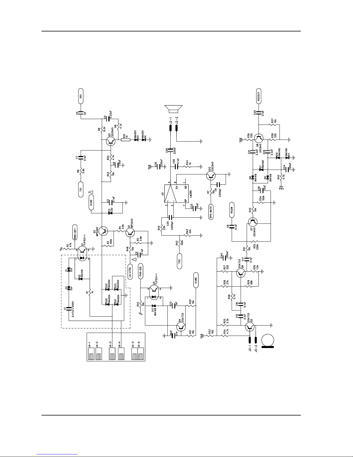
SCHEMATIC DIAGRAMS
The following schematic diagrams detail layout designs for the ISD-T360-based DAM.
Figure 1: Microphone and speaker circuitry
4
Voice Solutions in Silicon™
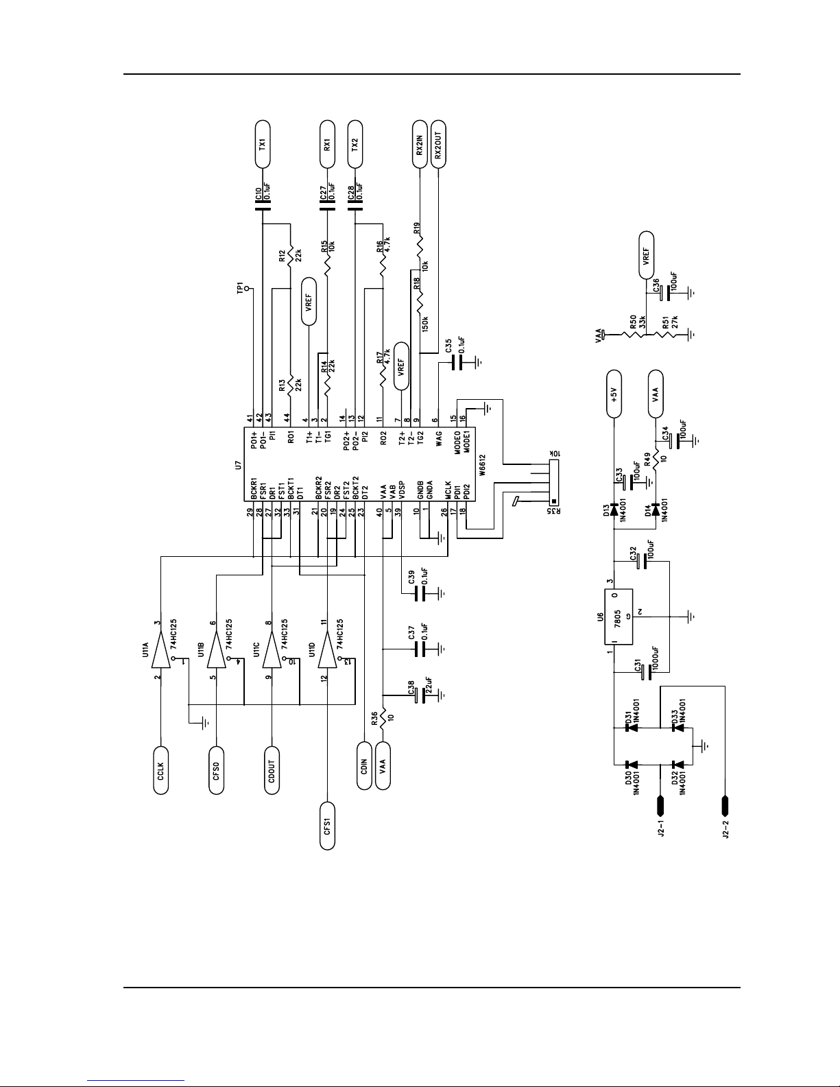
Figure 2: CODEC Interface
ISD-T360 Reference Design User’s Guide
ISD
5
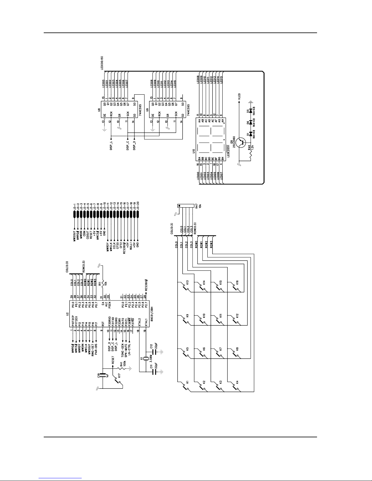
ISD-T360 Reference Design User’s Guide
Figure 3: Microcontroller I/O assignme nts
6
Voice Solutions in Silicon™
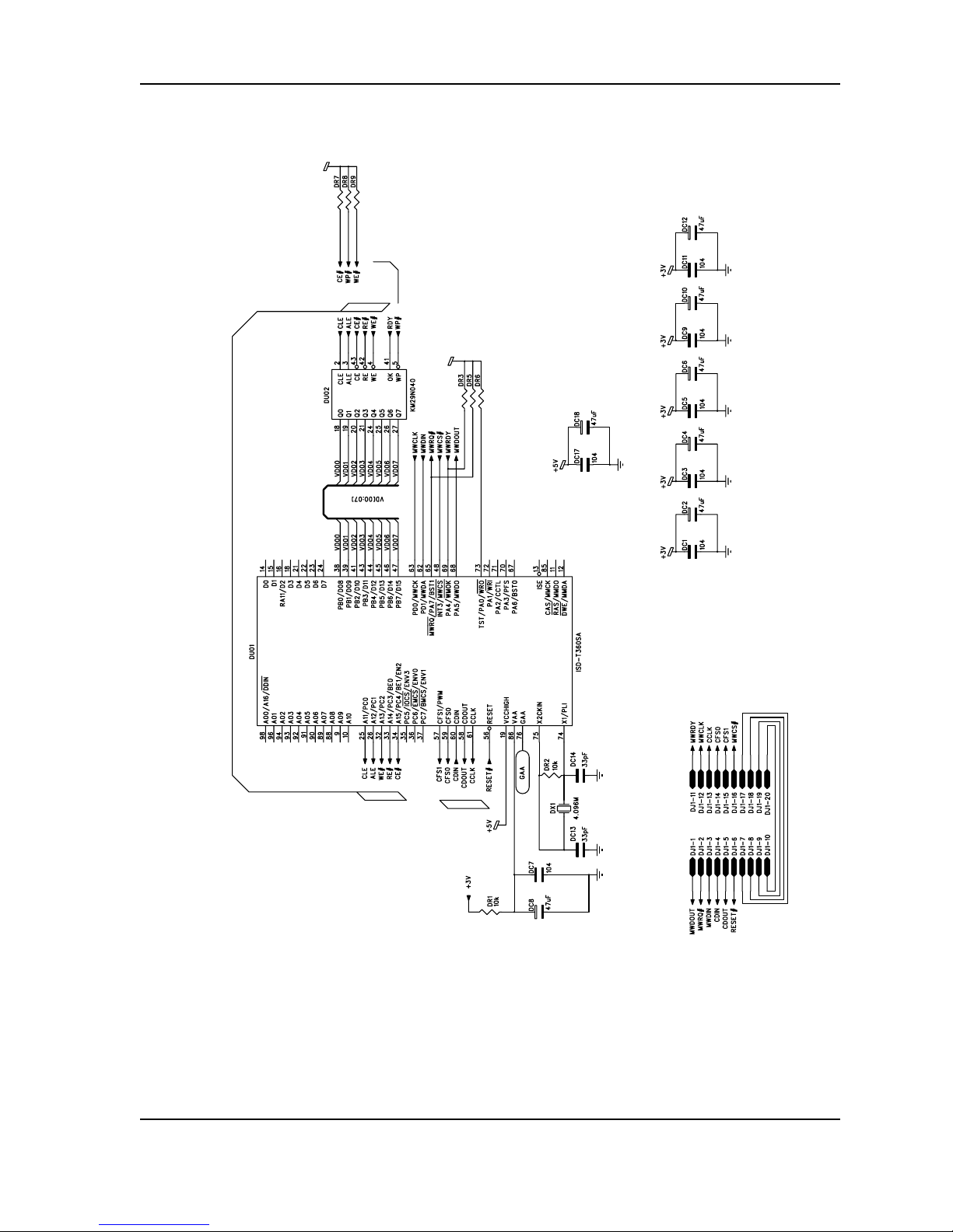
Figure 4: Memory Interface
ISD-T360 Reference Design User’s Guide
ISD
7

ISD-T360 Reference Design User’s Guide
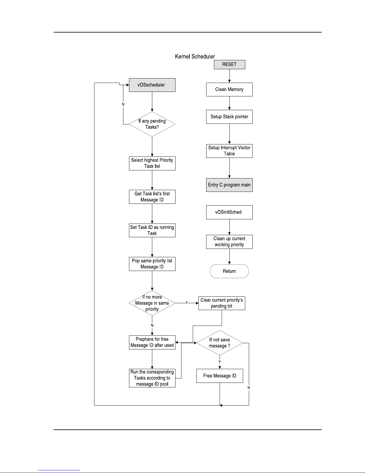
FLOW CHARTS FOR THE ISD-T360 DAM REFERENCE DESIGN
T360 REFERENCE DESIGN S/W STRUCTURE
The reference software code is written in C language for 8051microcontroller. It has a small kernel
and is easily integrated into an 8051-based system's software, such as Telephone Set, Caller ID systems, Cordless Phon e and PABX systems.
The software is comprised of three components:
Kernel
1.
Device driver
2.
Answer machine as the state machine
3.
Each of these components are detailed below.
Kernel
Timer: the timer has 6 software timers, which can start by any task and timeout to wake up any
•
other task.
Message Handler: the message handler has 10 message handlers for passing information
•
between tasks. Each message has a 1-byte message header and 2-bytes of data. This can be
easily increased by modifying the "include" file.
State Machine table : each task can setup its own state machine table. Th e Kernel's state con-
•
troller will search correspond ing task's state machin e table to find the correct messag e header,
then run the routine.
Device Driver
T360 driver: this driver includes microwire interface and commands sent to or received from
•
T360.
Ring Detection: d etects one ring pattern and th en sends a ring event to the A nswer machine
•
module. This detectio n may vary in some coun tries, thus requiring modific ation on the timing of
this module.
LED: sends data out to I/O pin for two 7-segment LED display.
•
KEY: scans the Key matrix and converts it to the corresponding key function required for Answer
•
machine module.
8051 driver: controls other I/O pins, such as on/off hook, speaker mute on/off.
•
Answer machine state Machine
TADmain: includes the state machine table; details of the state flow follow in the next section.
•
TAD function: in cludes function s called by th e state machine such as Autop lay message, Pl ay
•
one Message, Reco rding, Delete one message, Dele te all messages, etc.
TAD set: includes entry and exist of setting mode, and updates system information such as
•
CLOCK setting, Security Code setting, Answer On/Off option, etc.
8
Voice Solutions in Silicon™
ISD-T360 Reference Design User’s Guide
ISD
9
 Loading...