


SERIES 54XXA
SCALAR MEASUREMENT SYSTEMS
MAINTENANCE MANUAL
490 JARVIS DRIVE ● MORGAN HILL, CA 95037-2809
P/N: 10410-00123
PRINTED: AUGUST 1992
COPYRIGHT 1992 WILTRON CO.
REVISION: A

WARRANTY
The WILTRON product(s) listed on the title page is (are) warranted against defects in
materials and workmanship for one year from the date of shipment, except for YIG-tuned
oscillators, which are warranted for two years.
WILTRON’s obligation covers repairing or replacing products which prove to be defective
during the warranty period. Buyers shall prepay transportation charges for equipment
returned to WILTRON for warranty repairs. Obligation is limited to the original purchaser.
WILTRON is not liable for consequential damages.
LIMITATION OF WA RRANTY
The foregoing warranty does not apply to WILTRON connectors that have failed due to
normal wear. Also, the warranty does not apply to defects resulting from improper or
inadequate maintenance by the Buyer, unauthorized modification or misuse, or operation
outside of the environmental specifications of the product. No other warranty is expressed
or implied, and the remedies p rovided herein are the Buyer’s sole and exclusive remedies.

MANUAL CHANGES
MANUAL:
Title: Series 54XXA Scalar Measurement Systems Maintenance Manual
Part Number: 10410-00123
Rev. Ltr/Date: A / November 1992
CHANGE PAC KET
Part Number: 10900-00106
INSTRUCTIONS
1. Make the manual changes listed below. These changes are listed in numerical order by page number.
2. The replacement pages provided in this change package are for technical changes and errata to the
manual. The black bar or bars in the replacement page margins show the area in which the changes were
made.
CHANGE 1, Feb ruary 199 3:
Page 2-4:
1.
Replace with enclosed pages 2-3 and 2- 4, Changed: February 1993.
Pages 2-5 and 2-6:
2.
Replace with enclosed fold-out pages 2-5 and 2-6, Changed: February 1993.
Pages 6-24 and 6-25:
3.
Replace with enclosed pages 6-23 through 6-26, Changed: F ebruary 1993.
Pages A-5 and A-6:
4.
Replace with enclosed appendix pages A-5 and A-6, Changed: February 1993.
54XXA OM C-1

TABLE OF CONTENTS
Chapter 1 — General Service Information
This section provides a gene ral description of series 54XX A Scalar Measure ment Systems, system
serial numbers, and frequency ranges. It explains the level of maintenance covered in this manual
and provides pr eventative main tenance pr ocedures. I t also cont ains static-sen sitive comp onent handling precautions and a list of recomme nded test equipment.
Chapter 2 — Replaceable Parts
This Chapter lists all replaceable subassemblies and components for all 54XXA models. It e xplains
the WILTRON exchange assembly program and provides parts ordering information.
Chapter 3 — Troubleshooting
This chapter provides information for troubleshooting 54XXA Scalar Measurement Systems. The
troubleshooting information and fault location tables contained in this chapter s upport fault isolation down to a replaceable subasse mbly.
Chapter 4 — Functional Overview
This chapter provides descriptions of the functional operation of the major assemblies co ntained in
54XXA series Scalar Measurement S ystems. The operation of all major circuit blocks is described
so that the reader may better understand the function of each major assembly as part of the overall operation of the 54XXA.
Chapter 5 — Removal and Replacement Procedures
This chapter describes how to gain access to the major 54XXA assemblies and parts for troubleshooting or replacement.
Chapter 6 — Adjustments
This chapter provides adjustment procedures for all models of series 54XXA S calar Measurement
Systems. These procedures are used after replacement or repair of one or more critical subassemblies, or as indicated by the Pe rformance Verification Procedures (which are contained in S ection V
of the Series 54XXA Scalar M easurement Systems Operation Manual).
Appendix A — RF Detector Diode Replacement Procedures
This appendix contains rf detector diode re placement procedures for 5400-71XXX and 560-7XXX series RF Detectors.
54XXA MM i

Table of Contents (Continued)
Appendix B — Fabrication of RF Detector Simulator
This appendix contains information for fabricating the T1492 RF Detector Simulator test aid. This
test aid is used in the calibration pr ocedures contained in Chapter 6.
Appendix C — Fabrication of Dummy Thermistor Test Aids
This appendix contains information for fabricating the T38300 Dummy Down Conve rter Thermistor and the T38301 Dummy Directional Coupler Thermistor te st aids. These test aids are used in
the Temperature Compensation Adjustment Procedure for series 54XXA Scalar Measurement Systems contained in Chapter 6.
ii 54XXA MM

Chapter 1
General Service Information
Table of Contents
1-1 SCOPE OF THE MANUAL . . . . . . . . . . . . . . . . . . . 1-3
1-2 INTRODUCTION . . . . . . . . . . . . . . . . . . . . . . . . . 1-3
1-3 IDENTIFICATION NUMBER . . . . . . . . . . . . . . . . . . 1-3
1-4 DESCRIPTION OF 54XXA SYSTEM . . . . . . . . . . . . . . 1-3
1-5 LEVEL OF MAINTENANCE . . . . . . . . . . . . . . . . . . 1-4
Troubleshooting and Repair . . . . . . . . . . 1-4
Replaceable Subassemblies and Parts . . . . . 1-4
Adjustments . . . . . . . . . . . . . . . . . . . 1-4
Preventive Maintenance . . . . . . . . . . . . 1-5
1-6 RELATED MANUALS . . . . . . . . . . . . . . . . . . . . . . 1-5
1-7 PREVENTIVE MAINTENANCE . . . . . . . . . . . . . . . . 1-5
1-8 STATIC SENSITIVE COMPONENT HANDLING
PRECAUTIONS . . . . . . . . . . . . . . . . . . . . . . . . . 1-6
1-9 RECOMMENDED TEST EQUIPMENT . . . . . . . . . . . . 1-6
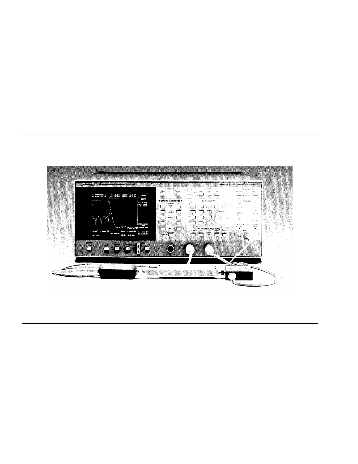
Figure 1-1. Model 5417A Scalar Measurement System with Detector and SWR Autotester (and T est Devi ce)

Chapter 1
General Service
Information
1-1
1-2
1-3
1-4
SCOPE OF THE MANUAL
INTRODUCTION
IDENTIFICATION NUMBER
DESCRIPTION OF 54XXA
SYSTEM
This manual provides general service and preventative maintenance information, replaceable parts information, circuit descriptions, troubleshooting procedures, and adjustment procedures for WILTRON se-
ries 54XXA Scalar Measurement Systems (SMS’s). Throughout this
manual, these systems are referred to as “54XXA”.
This chapter of the manual provides a general description of series
54XXA Scalar Measurement Systems, system serial numbers, frequency ranges, and related manuals. Also included is information
about the level of maintenance covered in this manual, preventative
maintenance procedures, and static-sensitive component handling precautions. A list of recommended test equipment is also provided.
All WILTRON instruments are assigned a six-digit ID number, such as
“101001.” This number appears on a decal affixed to the rear panel.
Please use this identification number during any corresponden ce with WILTRON Customer Service about this instrument.
Series 54XXA systems are microprocessor controlled scalar measurement systems. These systems are used to make scalar (magnitude)
transmission, reflection, and absolute power measurements. A typical
model is shown in Figure 1-1 (facing page). All measurement functions
are selectable by using the front panel keys and controls in conjunction
with the display screen menus. Refer to the 54XXA Scalar Measurement Systems Operation Manual for information about operation of
these systems. Refer also to that manual for information about system options, SWR Autotesters, detectors, and other accessories used with series
54XXA Syst ems.
54XXA MM 1-3
DESCRIPTION OF 54XXA GENERAL
SYSTEM SERVICE INFORMATION
Table 1-1. 54XXA Model Frequency
Ranges
Model Frequency Range (GHz)
5407A
5409A
5411A
5417A
5419A
5428A
5431A
5430A
5436A
5437A
5447A
1-5
LEVEL OF MAINTENANCE
0.001 to 1.0
0.001 to 2.0
0.001 to 3.0
0.01 to 8.6
2.0 to 8.6
8.0 to 12.4
10.0 to 16.0
12.4 to 20.0
17.0 to 26.5
2.0 to 20.0
0.01 to 20.0
The measurement frequency range of the 54XXA is determined by:
The range of the internal signal source of the particular model.
The external SWR Autotester and/or detector used with the
54XXA.
The table at left lists the frequency ranges of all 54XXA models. For information about the frequency ranges and characteristics of WILTRON
SWR Autotesters and RF detectors normally used with series 54XXA
models, refer to the 54XXA Scalar Measurement Systems Operation
Manual.
Option 3 to the 54XXA provides remote operation using the IEEE–488
General Purpose Interface Bus (GPIB). This option allows all 54XXA
front panel control functions (except POWER on/off) to be controlled remotely from an external computer/controller using GPIB commands.
Refer to the 54XXA Scalar Measurement Systems Operation Manual
for information about other options and accessories available for
54XXA models.
Maintenance and troubleshooting of the 54XXA consists of:
Troubleshooting the 54XXA to a replaceable subassembly
Repair by replacing the failed subassembly
Adjustments
Preventive maintenance
Troubleshooting and Repair
Most faults involving the 54XXA are field repairable
by replacing the subassembly that is at fault. The
procedures contained in this manual provide troubleshooting to this level. Refer to Chapter 3, Troubleshooting.
This manual also contains procedures for replacing
defective detector diodes for Series 560-7XXX RF Detectors and for 5400-71B75 RF Detectors. These procedures are contained in Appendix A.
Replaceable
Subassemblies
and Parts
Chapter 2 provides replaceable parts information for
all 54XXA models. It lists all field-replaceable subassemblies and parts. It also identifies all subasemblies that are presently covered by the WILTRON
exchange assembly program.
Adjustments Procedures for adjustment of the 54XXA after repair
or replacement of one or more subassemblies is described in Chapter 6, Adjustments.
1-4 54XXA MM
GENERAL SERVICE LEVEL OF
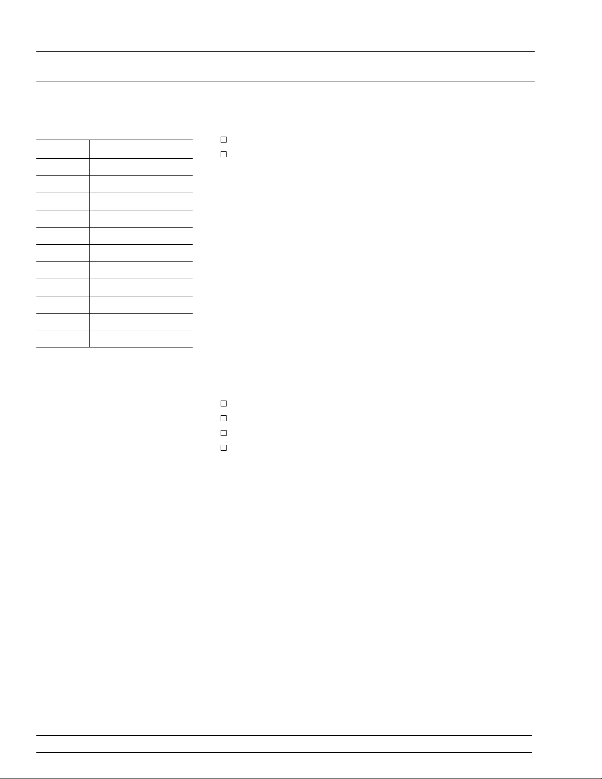
CAP NUTS (4)
FAN FILTER
FILTER GUARD
INFORMATION MAINTENANCE
1-6
1-7
RELATED MANUALS
PREVENTIVE
MAINTENANCE
Preventive
Maintenance
The 54XXA Scalar Measurement Systems Operation Manual (10410-
00118) describes the front panel operation for all 54XXA models. It also
contains general information, specifications, and Performance Verification procedures for all models.
Operation of the 54XXA remotely via the IEEE-488 General Purpose
Interface Bus (GPIB) is described in the 54XXA Series Scalar Measure-
ment Systems GPIB User’s Guide (10410-001 19). This user’s guide is
located at the rear of the 54XXA Scalar Measurement Systems Operation Manual.
The 54XXA must always receive adequate ventilation. Check and clean
the rear panel fan filter periodically. Clean this filter more frequently
in dusty environments. Proceed as follows:
Step 1 Remove the four capnuts holding the filter in place (Fig-
ure 1-2).
Step 2 Remove the filter.
Step 3 Clean the filter by flushing with compressed air.
Fan filter replacement, described in paragraph 1-7.
Step 4 Replace the filter by reversing the previous steps.
Step 5 Ensure that the cap nuts are securely tightened.
Figure 1-2. Fan Filter Removal/Replacement
54XXA MM 1-5

PREVENTIVE GENERAL SERVICE
MAINTENANCE INFORMATION
1-8
1-9
STATIC SENSITIVE
COMPONENT HANDLING
PRECAUTIONS
RECOMMENDED TEST
EQUIPMENT
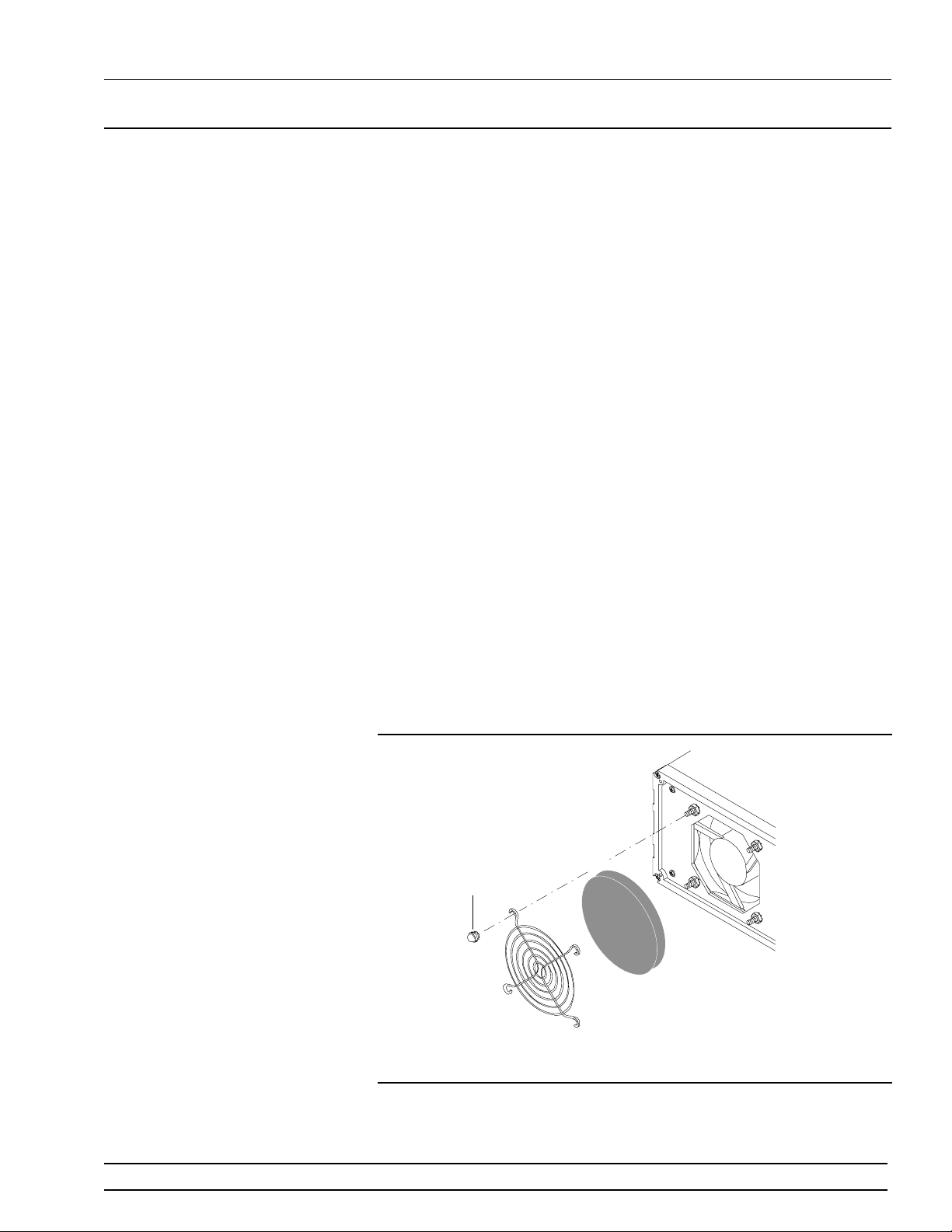
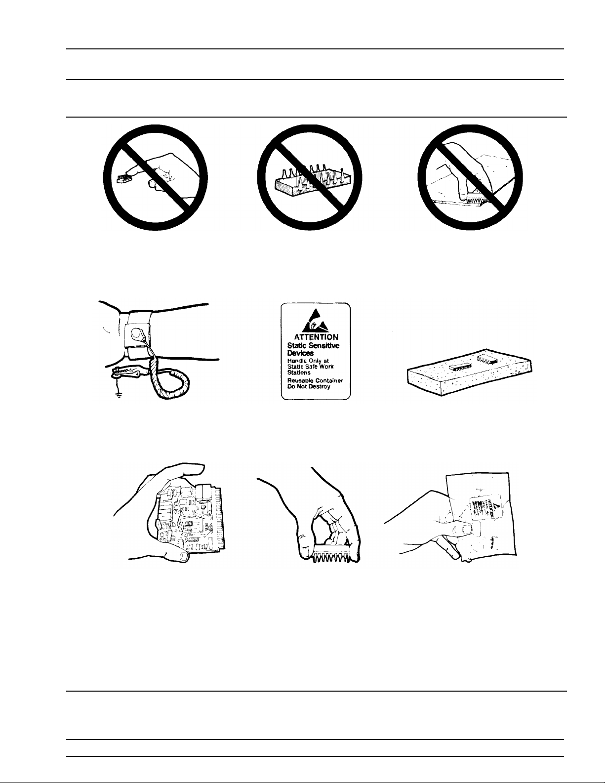
The 54XXA contains components that can be damaged by static electricity. Figure 1-3 illustrates the precautions that should be followed when
handling static-sensitive subassemblies and components. If followed,
these precautions will minimize the possibilities of static-shock damage to these items.
NOTE
Use of a grounded wrist strap when removing and/or replacing subassemblies or parts is strongly recommended.
The recommended test equipment for the adjustment and troubleshooting procedures presented in this manual are listed in Table 1-2.
1-6 54XXA MM
GENERAL STATIC HANDLING
INFORMATION PROCEDURES
Do not touch exposed contacts on
1.
any static sensitive component.
Wear a static-discharge wristband
4.
when working with static sensitive
components.
Do not slide static sensitive
2.
component across any surface.
Label all static sensitive devices.
5.
Do not handle static sensitive
3.
components in areas where the floor
or work surface covering is capable
of generating a static charge.
Keep component leads shorted
6.
together whenever possible.
Handle PCBs only by their edges.
7.
Do not handle by the edge
connectors.
Lift & handle solid state devices by
8.
their bodies – never by their leads.
Transport and store PCBs and other
9.
static sensitive devices in staticshielded containers.
10. ADDITIONAL PRECAUTIONS:
• Keep workspaces clean and free of any objects capable of holding or storing a static charge.
• Connect soldering tools to an earth ground.
• Use only special anti-static suction or wick-type desoldering tools.
Figure 1-3. Static Sensitive Component Handling Procedures
54XXA MM 1-7

RECOMMENDED GENERAL SERVICE
TEST EQUIPMENT INFORMATION
Tab l e 1-2. Recommended T est Equipment
INSTRUMENT
Adaptor Cable Connection to 54XXA Channel Inputs WILTRON Model 560-10BX
Detector Simulator Simulates WILTRON RF Detectors WILTRON T1492 (see Appendix B)
Computer/Controller Personal computer, equipped with
National PCIIA GPIB interface card
RF Detector 1. 50Ω input, 1.0 to 3000 MHz*
2. 75Ω input, 1.0 to 3000 MHz**
3. 0.010 to 18.5 GHz
4. 0.010 to 26.5 GHz
CRITICAL
SPECIFICATION
‡
Any IBM compatible (or WILTRON
Model 85, or HP Model 200)
WILTRON Mode l 54 00 -7 1N 5 0
WILTRON Mode l 54 00 -7 1N 7 5
WILTRON Mode l 56 0-7N50
WILTRON Mode l 56 0-7K50
Impedance Adapter Converts from 50Ω to 75Ω WIL TRON Model 12N75B
Digital Multimeter Resolution: 4-1/2 digits (to 20V )
DC Accuracy:
DC Input Impedance:
AC Accuracy:
0.002% + 2 counts
10 MΩ
0.07% +100 cts (≤20 kHz)
John Fluke Mfg Co. Inc.,
Model 8840A, wit h
Option 8840A-09, True RMS AC
AC Input Impedance: 1 MΩ
Frequency Counter
Modulation Meter
Oscilloscope
Power Meter, with:
Power Sensor*
50Ω input
Power Sensor**
75Ω input
Frequency:
Input Impedance
Bandwidth:
Accuracy: ±3% of FSD at 1 kHz
Bandwidth
Sensitivity:
Horiz. Sensitivity:
Power Range:
Other:
Frequency Range : 1.0 MHz to 2.0 GHz
Power Range:
Frequency Range : 1.0 MHz to 5.5 GHz
Power Range:
0.1 to 26.5 GHz
: 50Ω
15 kHz
: DC to 100 MHz
2 mV
50 ns/division
+10 to –55 dBm
50 MHz Calibrated Output
–30 to +20 dBm Anritsu Corp., Model MA4601A
–30 to +20 dBm
EIP Microwave, Inc., Model 578A
Marconi Instrum en ts Inc .,
Model 2304
Tektronix, Inc.
Model 2445
Anritsu Corp., Mod el ML 48 03 A
Anritsu Corp., Model MA4603A
with J0365 Conversion Connector
Power Sensor Frequency Range: 0.10 to 18.0 GHz
Power Sensor#
Atten, Calibration
Power Range:
Power Range:
Frequency Range: 0.05 to 26.5 GHz
Power Range:
Power Range:
Atten: 30 dB, used with MA47 02 A/0 4A
–30 to +20 dBm
–70 to –20 dBm
–30 to +20 dBm
–70 to –20 dBm
Anritsu Corp., Model MA4701A
Anritsu Corp., Model MA4702A
Anritsu Corp., Model MA4703A
Anritsu Corp., Model MA4704A
Anritsu Corp., Model MP47A
Printer Parallel Interface operation WILTRON, Model 2225C Ink Jet
Printer, or equivalent
Spectrum Analyzer
Frequency Range:
0.01 to 26.5 GHz
Anritsu Corp., Model MS2802
Power Range: +10 dB to –60 dBm
Step Attenuat or
Attenuation Ran ge :
0.000 to 18.0 GHz
0.000 to 26.5 GHz
Voltage Standard Range: 0 mV to –1 .4 62V
Accuracy: 0.00 2% of set value.
∗ Required for models 5407A, 5409A, and 5411A with 50Ω output.
∗∗ Required for models 5407A, 5409A, and 5411A with 75Ω output, only.
#
Required for model 5436A, only.
60 dB, 10 dB/step
Hewlett-Packard, Model 8495B
Hewlett-Packard, Model 8495D
John Fluke Mfg Co. Inc.,
Model 335D
# Use Code:
RECOMMENDED
MANUFACTURER/MODEL
A Adjustment
P Performance verification procedures
T Troubleshooting
USE
P, A
A
P, T
P, A
P, A, T
A, T
P, A
P, A
A, T
P, T
P, T
P, T
P, A
P, A, T
#
1-8 54XXA MM

Chapter 2
Replaceable Parts
Table of Contents
2-1 INTRODUCTION . . . . . . . . . . . . . . . . . . . . . . . . . 2-3
2-2 EXCHANGE ASSEMBLY PROGRAM . . . . . . . . . . . . . 2-3
2-3 REPLACEABLE SUBASSEMBLIES AND PARTS . . . . . . . 2-3
2-4 PARTS ORDERING INFORMATION . . . . . . . . . . . . . . 2-3

Chapter 2
Replaceable Parts
2-1
2-2
2-3
INTRODUCTION
EXCHANGE ASSEMBLY
PROGRAM
REPLACEABLE
SUBASSEMBLIES AND
PARTS
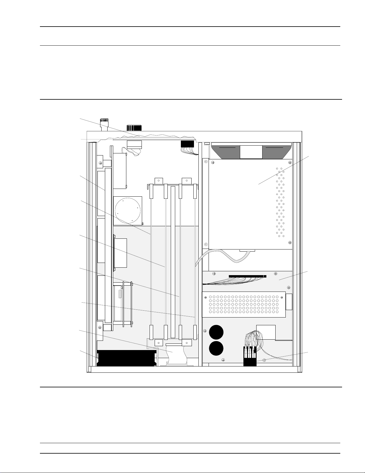
This chapter provides replaceable parts information for all 54XXA models. The location of the major replaceable assemblies is shown in Figures 2-1 and 2-2 (pages 2-7 and 2-8).
WILTRON maintains a module exchange program for selected subassemblies of all 54XXA models. If a malfunction occurs in one of these
subassemblies, the defective item can be exchanged. Upon receiving
your request, WILTRON will ship the exchange subassembly to you,
typically within 24 hours. You then have 30 days in which to return
the defective item. All exchange subassemblies or RF assemblies are
warranted for 90 days from the date of shipment, or for the balance of
the original equipment warranty, whichever is longer.
Please have the exact model number and serial number of your unit
available when requesting this service, as the information about your
unit is filed according to the instrument’s model and serial number.
For more information about the program, contact your local sales representative or call WILTRON Customer Service direct (paragraph 2-4).
Table 2-2 (page 2-5) lists the major replaceable subassemblies and
parts for the 54XXA that are presently covered by the WILTRON
exchange assembly program. Table 2-3 and Table 2-4 (page 2-6) list
model-dependent and common replaceable parts for the 54XXA that
are not presently on the exchange assembly program.
2-4
PARTS ORDERING
INFORMATION
All parts listed in Tables 2-2 through 2-4 may be ordered from your local WILTRON service center (Table 2-1). Or, they may be ordered directly from the factory at the address shown below.
WILTRON Company
ATTN: Customer Service
490 Jarvis Drive
Morgan Hill, CA 95037-2809
Telephone: (408)-778-2000
TWX: 285227 WILTRON MH
FAX: (408)-778-0239
54XXA MM 2-3

WILTRON REPLACEABLE
SERVICE CENTERS PARTS
Table 2-1. WILTRON Service Centers
UNITED STATES
WILTRON COMPANY
490 Jarvis Drive
Morgan Hill, CA 95037-2809
Telephone: (408) 778-2000
Telex: 285227 WILTRON MH
FAX: (408) 778-0239
ANRITSU WILTRON SALES
COMPANY
685 Jarvis Drive
Morgan Hill, CA 95037-2809
Telephone: (408) 776-8300
FAX: (408) 776-1744
ANRITSU WILTRON SALES
COMPANY
15 Thornton Road
Oakland, NJ 07436
Telephone: (201) 337-1111
FAX: 201-337-1033
AUSTRALIA
WILTRON PTY. LTD..
1/410 Church Street
North Parramatta
NSW 2151 Australia
Telephone: (02) 6308166
Fax: (02) 6836997
BRAZIL
ANRITSU ELECTRONICA S.A.
Av. Passos, 91-Sobrelojas
203/205-Centro
20.051 Rio de Janeiro-RJ
Telephone: (011) 2853091
Telex: 11 33532 ANBR BR
Fax: (011) 2886940
CANADA
WILTRON INSTRUMENTS LTD.
215 Stafford Road, Unit 102
Nepean, Ontario K2H 9C1
Telephone: (613) 726-8800
FAX: (613) 820-9525
CHINA
WILTRON BEIJING SERVICE
CENTER
416 W Beijing Fourtune Bldg
5 Dong San Huan Bei Lu
Chao Yang Qu, Beijing, China
Telephone: (861) 501-7559
FAX: (861) 501-7558
(861) 501-7553
FRANCE
WILTRON S.A
9 Avenue du Quebec
Zone de Courtaboeuf
91951 Les Ulis Cedex
Telephone: (01) 64-46-65-46
FAX: (01) 64-46-10-65
INDIA
ACCUTROL SYSTEMS PRIVATE
LIMITED
Nirmal, 15th Floor
Narimen Point
Bombay 400 021
Telephone: 011-91-22-202-2220
: 011-91-22-204-7187
FAX: 011-91-22-202-9403
ISRAEL
TECH-CENT, LTD
7A, Pinhas Rosen Street
Tel-Aviv 69356
Telephone: (03) 481958
FAX: (03) 481958
ITALY
WILTRON Sp.A
Roma Office
Via E. Vittorini, 129
00144 Roma EUR
Telephone: (06) 5005171
FAX: (06) 5005273
JAPAN
ANRITSU CORPORATION
1800 Onna Atsugi-shi
Kanagawa-Prf. 243 Japan
Telephone: 0462-23-1111
FAX: 0462-25-8379
KOREA
WILTRON CORPORATION
1201 Sinsong Bldg. 12F,
25-4 Yeoeuido-Dong
Youngdeungpo-ku, Seoul
Telephone: (02) 785-6407
FAX: (02) 784-6409
SWEDEN
WILTRON AB
Box 247
S-127 25 Skarholmen
Telephone: (08) 7405840
Telex: (854) 8135089
FAX: (08) 7109960
TAIWAN
WILTRON CO., LTD.
8F, No. 96, Section 3
Chien Kuo N. Road
Taipei, Taiwan, R.O.C.
Telephone: (02) 515-6050
FAX: (02) 505-5519
UNITED KINGDOM
ANRITSU EUROPE LTD.
Capability Green
Luton, Bedfordshire
LU1 3LU, England
Telephone: (0582) 418853
Telex: (851) 826750
FAX: (011) 582-31303
WEST GERMANY
WILTRON GmbH
Rudolf Diesel Str 17
8031 Gilching
Telephone: (08105) 8055
Telex: (841) 528523
FAX: (08105) 1700
2-4 54XXA MM
Changed: February 1993

REPLACEABLE PARTS
PARTS LISTS
Table 2-2. Exchange Assembly Program 54XXA Subassemblies and Parts
Reference
Designator
A1
A2
A3
A5
A6
A7
A8
A10
A11
A12/A13
A14
A17
A18
A19
54XXA
Option
Front Panel PCB D35051-3 D35051-3 D35051-3 D35051-3 D35051-3 D35051-3 D35051-3 D35051-3 D35051-3 D35051-3 D35051-3
Front Panel Interface PCB D35052-3 D35052-3 D35052-3 D35052-3 D35052-3 D35052-3 D35052-3 D35052-3 D35052-3 D35052-3 D35052-3
Signal Channel PCB (std) D35345-3 D35345-3 D35345-3 D35345-3 D35345-3 D35345-3 D35345-3 D35345-3 D35345-3 D35345-3 D35345-3
Option 5
Option 3 Central Processor/GPIB PCB w GPIB D35357-4 D35357-4 D35357-4 D35357-4 D35357-4 D35357-4 D35357-4 D35357-4 D35357-4 D35357-4 D35357-4
Signal Channel PCB (
YIG Driver/Signal Channel Intf. PCB
ALC/Frequency Instruction PCB ND37738-1 ND37738-2 ND37738-3 ND37738-4 ND37738-4 ND37738-4 ND37738-4 ND37738-4 ND37738-4 ND37738-4 ND37738-4
Central Processor/GPIB PCB w/o GPIB
Graphics Processor PCB D35066-3 D35066-3 D35066-3 D35066-3 D35066-3 D35066-3 D35066-3 D35066-3 D35066-3 D35066-3 D35066-3
Menu PCB Assembly C35060-3 C35060-3 C35060-3 C35060-3 C35060-3 C35060-3 C35060-3 C35060-3 C35060-3 C35060-3 C35060-3
500 MHz Sample/Marker Assembly C35329 C35329 C35329 C35329 C35329 C35329 C35398 C35398
500 MHz VCO/PA Assembly C35192 C35192 C35192 C35192 C35192 C35192 C35396 C35396
25 MHz Marker A s s e mbly C35194-11 C35194-11 C35194-7 C35194-7 C35194-7 C35194-7 C35397 C35397
RF Deck Distribution Panel Assembly (PCB) C35287-3 C35287-3 C35287-3 C35287-3 C35287-3 C35287-3
Switched Filter Driver Assembly (PCB) C35286-3 C35286-3
Multiband Controller Assembly D35430-3 D35430-3
Power Supply Assembly * D35370 D35370 D35370 D35370 D35370 D35370 D35370 D35370 D35370 D35370 D35370
CRT Monitor Assembly D35047 D35047 D35047 D35047 D35047 D35047 D35047 D35047 D35047 D35047 D35047
Assembly/Part 5407A 5409A 5411A 5417A 5419A 5428A 5430A 5431A 5436A 5437A 5447A
w/R input)
D35053-3 D35053-3 D35053-3 D35053-3 D35053-3 D35053-3 D35053-3 D35053-3 D35053-3 D35053-3 D35053-3
D35358-10 D35358-10 D35358-10 D35358-4 D35358-4 D35358-5 D35358-6 D35358-7 D35358-8 D35358-9 D35358-9
D35357-3 D35357-3 D35357-3 D35357-3 D35357-3 D35357-3 D35357-3 D35357-3 D35357-3 D35357-3 D35357-3
Option 2 Step Attenuator Assembly, 70 dB, 3 GHz D24335 D24335 D24335
Option 2A Step Attenuator Assembly, 70 dB, 20 GHz 4412K 4412K 4412K 4412K 4412K 4412K 4412K
Option 2B Step Attenuator Assembly, 70 dB, 26.5 GHz 4512K
Output Coupler D21450 D21450 D21450 D21450 D21450 D21452 D21450 D21450
Down Converter D25472 D25472 D25472 D25471 D25471
Modulator Assembly D22870 D22870 D22880 D22900 D22890 D22910
Switched Filter Assembly ND39316 ND39316 D22040 D22040
3 GHz Marker Assembly D25432 D25432 D25432 D25432 D25432
2 GHz Marker Assembly C30954-1
YIG Oscillator C22550 C22550 C22550
∗ For instruments with serial numbers 103014 and below, use Power Supply Assembly ND37737.
∗∗ For Models 5417A and 5419A with 8.4 GHz upper band-edge, use YIG Oscillator C22570.
C24436
∗∗
C24436
∗∗
C11282 C14770-1 C22560 C29963 C21620 C21620
54XXA MM 2-5
Changed: February 1993
PARTS REPLACEABLE
LISTS PARTS
Table 2-3. Model Related 54XXA Replaceable Subassemblies and Parts
Assembly/Part 5407A 5409A 5411A 5417A 5419A 5428A 5430A 5431A 5436A 5437A 5447A
RF Output Connector, 50 Ω, Type N
RF Output Connector, 50
RF Output Conector, 75
Ω, Type K
Ω, Type N
∗
B35283 B35283 B35283 C18650-1 C18650-1 C18650-1 C18650-1 C18650-1 C18650-1 C18650-1
C18640-1
B35284 B35284 B35284
Front Panel Overlay
Front Panel Overlay (for units w/Option 5
∗ 54XXA Option 4 (5407A, 5409A and 5411A, only)
∗∗ Third front panel input
# For units with 8.6 GHz upper band edge.
∗∗
)
D35026-10 D35026-11 D35026-12 D35026-13 D35026-14 D35026-15 D35026-16 D35026-17 D35026-18 D35026-22 D35026-20
D35026-2
D35026-1 D35026-2 D35026-3 D35026-4 D35026-5 D35026-6 D35026-7 D35026-8 D35026-9 D35026-21 D35026-19
D35026-2
#
4
#
3
D35026-26
D35026-25
#
#
Table 2-4. Common 54XXA Replaceable Subassemblies and Parts
Assembly/Part
Cover, Top D30125 Fuse, 4A, 3AG Slow Blow (115 Vac Operation) 631-16
Cover, Bottom D30126 Fuse, 2A, Time Lag, 20 mm (230 Vac Operation) 631-67
Cover, Side D30127 Fuse Holder, 3AG Type 533-221
Cover, Side (modified, with holes) C30051 Fuse Holder, 5 x 20 mm Type 533-240
Connector, Front Panel Input 557-152 Knob, Data Entry 710-62
Part
Number
Assembly/Part
Number
Part
Fan Assembly, Rear Panel C35215 Line Module Assembly, Rear Panel B35375
Fan Filter 783-377
Finger Guard, Fan 790-251 Tilt Bail C13654
Dome Nut, (for Finger Guard) 900-579
Foot, Rear D13656
Foot, Bottom D13655
2-6 54XXA MM
Changed: February 1993
DANGER
HIGH VOLTAGE
A1
FRONT PANEL
PCB
A2
FRONT PANEL
INTERFACE
PCB
RF DECK
ASSEMBLY
CRT
MONITOR
ASSEMBLY
POWER
SUPPLY
ASSEMBLY
LINE VOLTAGE
SELECTOR
MODULE
REAR PANEL
FAN ASSEMBLY
A5
YIG DRIVER/
SIGNAL
CHANNEL
INTERFACE
PCB
A6
ALC/
FREQUENCY
INSTRUCTION
PCB
A7
CENTRAL
PROCESSOR/
GPIB PCB
A8
GRAPHICS
PROCESSOR
PCB
REAR PANEL
CONNECTORS
REPLACEABLE MAJOR ASSEMBLIES
PARTS LOCATION DIAGRAM
Figure 2-1. 54XXA Major Assemblies Location Diagram (Top View)
54XXA MM 2-7
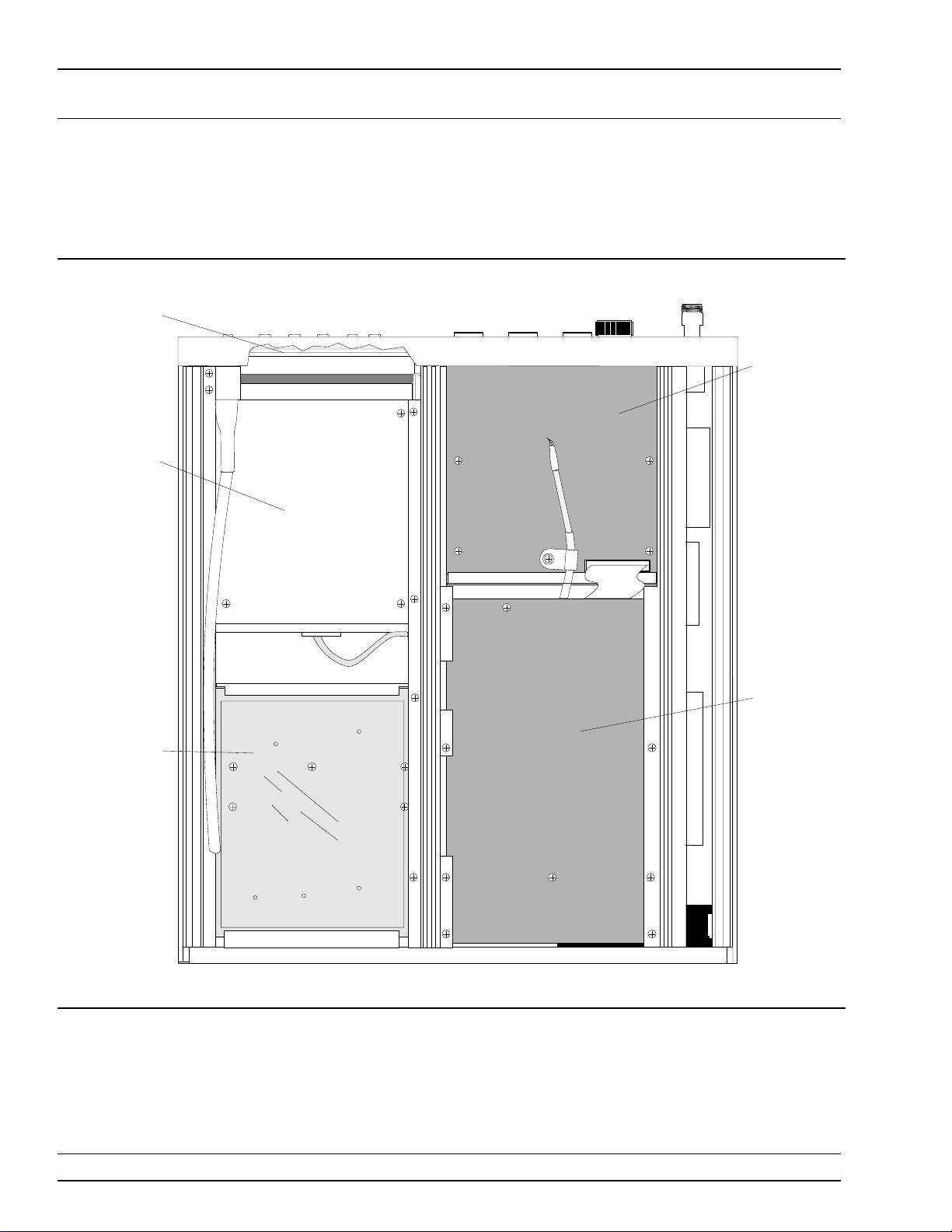
MAJOR ASSEMBLIES REPLACEABLE
LOCATION DIAGRAM PARTS
A10
MENU PCB
ASSEMBLY
A3
SIGNAL
CHANNEL
PCB
CRT MONITOR
ASSEMBLY
POWER SUPPLY
ASSEMBLY
Figure 2-2. 54XXA Major Assemblies Location Diagram (Bottom View)
A4
MOTHERBOARD
PCB
2-8 54XXA MM

Chapter 3
Troubleshooting
Table of Contents
3-1 INTRODUCTION . . . . . . . . . . . . . . . . . . . . . . . . . 3-3
3-2 RECOMMENDED TEST EQUIPMENT . . . . . . . . . . . . 3-3
3-3 POWER-UP AND SELF TEST DIAGNOSTICS . . . . . . . . 3-3
Power-up and Self Test Errors . . . . . . . . . . . 3-3
Calibration Errors . . . . . . . . . . . . . . . . . . 3-4
Normal Operation Error and Warning Messages . 3-4
3-4 MALFUNCTIONS NOT DISPLAYING ERROR MESSAGES . 3-4
3-5 TROUBLESHOOTING TABLES . . . . . . . . . . . . . . . . 3-4

Many of the troubleshooting procedures presented in this chapter require the removal of instrument covers to gain access to printed circuit
assemblies and other major assemblies.
WARNING
Hazardous voltages are present inside the instrument when ac line power is connected. Turn off the
instrument and remove the line cord before removing any covers or panels. Trouble shooting or repair
procedures should only be performed by service personnel who are fully aware of the potential hazards.
CAUTION
Many assemblies in the 54XXA contain static-sensitive compon ents. Improper handling of these assemblies may result in damage to the assemblies.
Always observe the static-sensitive component handling precautions described in Chapter 1, Figure 1-3.

Chapter 3
Troubleshooting
3-1
3-2
3-3
INTRODUCTION
RECOMMENDED TEST
EQUIPMENT
POWER-UP AND SELF
TEST DIAGNOSTICS
This chapter provides information for troubleshooting 54XXA Scalar
Measurement Systems. The troubleshooting operations presented in
this chapter support fault isolation down to a replaceable subassembly.
(Remove and replace procedures for major 54XXA assemblies are contained in Chapter 5.)
The recommended test equipment for the t roubleshooting operati ons
presented in this chapter is listed in Chapter 1, Table 1-2 (page 1-8).
The 54XXA firmware includes internal diagnostics that are initiated
during power-up of the unit, or when the SELF TEST key is pressed.
These diagnostics also check for fault conditions during normal operation. Any fault or error conditions found are reported as described below. Tables 3-1 and 3-2 (pages 3-5 and 3-6) list all possible error messages. For each specific error message, the table provides either a
possible cause of the fault, or a reference to another troubleshooting table that contains more detailed troubleshooting operations. There are
three primary types of error messages that are reported by the diagnostics:
Power-up and Self Test Errors
Calibration Errors
Normal Operation Error and Warning Messages
Power-up
and Self Test
Errors
Serious system malfunctions detected during powerup or Self Test will be flagged by a bold FAILED
TESTS CRT display. Specific fault messages will also
be reported; for example: A7 GPIB Interface fail.
These “self test” fault conditions are also indicated
by means of one or more flashing front panel LED indicators. A specific LED flashes steadily after completion of the self test for each fault detected. Table
3-1 shows which error message and LED indicator
correspond to each majo r fault condition. Note that
the flashing LED indicator provides exactly the
same information as the CRT failure message;
should the CRT fail, this technique can be used as a
troubleshooting aid. The faults listed in Table 3-1
generally indicate malfunctions in the major PCB assemblies of the 54XXA.
54XXA MM 3-3

POWER-UP AND
SELF TEST DIAGNOSTICS TROUBLESHOOTING
Calibration
Errors
Normal Operation Error
and Warning
Messages
After self test, and prior to starting normal operation, the 54XXA performs an internal frequency lock
calibration. These calibrations are also performed periodically during normal operation. If a frequency
calibration test fails, one or more “calibration error”
messages will be displayed along with the FAILED
TESTS display (example: fails het band 500 miss); re-
fer to Tables 3-2a and 3-2b. Calibration error messages generally indicate RF deck related problems.
During normal operation, a failed calibration is indicated by a failure code displayed in the lower right
corner of the screen display (described below). These
error codes are listed in Table 3-3 along with suggested remedial action.
When an abnormal condition is detected during normal operation, an error or warning messages is displayed in the message box located in the lower right
corner of the screen display, as described below. If
more than one fault is detected, the highest priority
error message will be displayed. Error messages
take precedence over warning messages.
Error Messages — These messages report malfunctions that occur either during self test or during normal operation. They can be identified by the presence of a failure code; example: 500 MHz markers 201.
Table 3-3 lists these codes and suggested remedies.
3-4
3-5
MALFUNCTIONS NOT
DISPLAYING ERROR
MESSAGES
TROUBLESHOOTING
TABLES
Warning Messages — These messages report procedural errors; example: NO CAL DATA. They do not
report fault conditions or malfunctions, but they do
indicate that an invalid operation has been attempted. A Warning message can be distinguished
from an error message by the absence of an error
code following the message. Refer to the 54XXA Operation Manual, Appendix A, Table A-3, for descriptions of warning messages and remedies.
Some major system malfunctions may not cause an error message or error code to be displayed. These include problems with the RF deck,
CRT monitor, and power supply. Troubleshooting procedures for these
problems are provided in Tables 3-8 through 3-22, which begin on
page 3-14.
Tables 3-4 through 3-23 that begin on page 3-9 provide procedures for
isolating malfunctions to a replaceable subassembly. In cases where
any of several subassemblies are suspect, subassembly replacement is
indicated. The recommended replacement order is for the most-likely
subassemblies to be replaced first.
3-4 54XXA MM

SELF-TEST
TROUBLESHOOTING ERROR MESSAGES
Table 3-1. Error Messages and Front Panel LED Indicators for Power-Up/Self Test Errors
Condition/Fault Associated Front Panel LED Recommended Action
CPU ASM test running HARDCOPY PRINTER PRINTER LED normally flashes during Sel f Test .
A6 PERSONALITY fail HARDCOPY PLOTTER Replace A6 PCB *.
A7 EPROM U32 check sum fail CURSOR ON/OFF Replace A7 PCB *.
A7 EPROM U31 check sum fail CURSOR RELATIVE Replace A7 PCB *.
A7 EPROM U30 check sum fail DISPLAY, CHAN 1 Replace A7 PCB *.
A7 PROGRAM RAM fail DISPLAY, CHAN 2 Replace A7 PCB *
A8 LOAD GSP fail AVERAGING, CHANNEL 1 Replace A8 PCB *
A8 PIPE INTERFACE fail AVERAGING, CHANNEL 2 Replace A8 PCB *.
A7 NON VOLATILE RAM fail SMOOTHING, CHAN’S 1 & 2 Replace A7 PCB *.
A7 INTERRUPT CONTROLLER fail LEVELING, INTERNAL Replace A7 PCB *.
A7 TIMESLICE GENERATOR fail LEVELING, EXTERNAL Replace A7 PCB *.
A7 GPIB Interface fail UNLEVELED Replace A7 PCB *.
A2 KEYBOARD INTERFACE fail REMOTE Replac e A2 PCB. Ref er to PCB removal
procedures , paragraph 5-6.
A3 SIGNAL CHANNEL PRESENT
or A5 SIGNAL CHANNEL ADC fail
Self Test completed TRACE HOLD TRACE HOLD LED flashes briefly at end of
CALIBRATION UNCAL Replace A3 PCB, then Replace A5 PCB, as
necessary. Refer to PCB removal procedures,
paragraphs 5-3 and 5-4.
Self Test.
∗ Refer to PCB removal procedures, paragraph 5-3.
54XXA MM 3-5

DISPLAYED
ERROR MESSAGES TROUBLESHOOTING
Tables 3-2a & 3-2b. Displayed Error Message Headings and Message Text for Calibration Related Faults/Errors
3-2a
ERROR MESSAGE HEADINGS*
Heading Category/Type Message Meaning
GENERAL Major errors no 500 500 MHz markers cannot be found during
STARTMAIN
ERROR Calibration of ERROR DAC
WIDTHMAIN
WIDTH-FM Calibration of WIDTH DAC (using
HET BAND Verification of Downconverter
Calibration of START DAC (using
main coil)
(using FM coil)
Calibration of WIDTH DAC (using
main coil)
FM coil)
and 25 MHz Marker Box operation
500 miss 500 MHz marker missing during START-MAIN DAC
1st wrong For START-MAIN DAC or WIDTH-MAIN DAC
500 size 500 MHz markers not large enough during START-
spacing Cannot find two markers with correct spacing in
Error Codes
210 to 212
ERROR MESSAGE TEXT*
GENERAL test
or WIDTH-MAIN DAC calibrations
calibrations: Cannot find two markers with correct
spacing in first group of three at top of frequency
range.
For HET BAND calibration: Offset between main
band 500 MHz markers and HET band 25 MHz
markers is out of specification.
MAIN DAC or WIDTH-MAIN DAC calibrations
group of three during ERROR, WIDTH-FM, or HET
BAND calibrations (using FM coil).
This series of error codes will be displayed after a
Frequency Calibration if an error occurs (Refer to
paragraph 3-3 and Table 3-3.).
3-2b
Error Codes
213 and
above
* These headings and messages are displayed on the CRT Monitor. When 54XXA reverts to normal screen display, the corresponding error
codes will be displayed in the lower right corner of the screen display. The error codes are described in Table 3-3.
This series of error codes will be displayed only
during fault diagnosis in the Engineering Mode of
operation. To put 54XXA in this mode, refer to
paragraph 6-4, step 3, on page 6-7. Then press
DATA ENTRY keys “4 and “1” in sequence to turn on
Calibration Error Codes. To return to normal mode,
press SELF TEST key. Refer Table 3-3 for
explanations of the error codes.
3-6 54XXA MM

CALIBRATION RELATED
TROUBLESHOOTING ERROR CODES
Table 3-3. Error Codes for Calibration Related Faults/Errors (1 of 2)
Calibration
Error Code
201
202
203
204
205
206
207
208
209
210
211
212
213
Error Description
General, no 500 MHz or 75 MHz markers
START DAC main band, 500 MHz or 75 MHz marker(s) missing; or, top or bottom
frequency(s) not correctly set
START DAC main band, 1st MHz markers (top) wrong
START DAC main band, 500 MHz or 75 MHz marker size error
ERROR DAC, 25 MHz marker spacing wrong
WIDTH DAC main band, 500 MHz or 75 MHz marker(s) missing
WIDTH DAC main band, 1st MHz markers (top) wrong
WIDTH DAC main band , 50 0 MH z or 75 MH z marker size error
WIDTH DAC fm, 25 MHz marker spacing wrong
HET band, 500 MHz or 75 MHz marker missing
HET band, 25 MHz and 50 0 MHz mark er sp ac in g w rong
HET band, 25 MHz marker spacing wrong
Start lb, START DAC, 500 MHz or 75 MHz marker missing
Refer
to Table:
3-4
3-4
3-5
3-5
3-6
3-4
3-5
3-5
3-6
3-4
3-6
3-6
3-4
214
215
216
217
218
219
220
221
222
223
224
225
226
227
Start lb, 25 MHz slow lock fail
Stop lb, WIDTH DAC, 500 MHz or 75 MHz marker missing
Stop lb, 25 MHz slow lo ck fail
Start mb, START DAC, 500 MHz or 75 MHz marker missing
Start mb, 25 MHz slow lock fail
Stop mb, WIDTH D AC , 50 0 MH z or 75 MHz marker missing
Stop mb, 25 MHz slow lo ck fail
Start hb, START DAC, 500 MHz or 75 MHz marker missing
Start hb, 25 MHz slow lock fail
Stop hb, WIDTH DAC, 500 MHz or 75 MHz marker missing
Stop hb, 25 MHz slow lock f ai l
lb chan1 error, multiple slow lock fail
lb chan2 error, multiple slow lock fail
mb chan1 error, multiple slow lock fail
3-6
3-4
3-6
3-4
3-6
3-4
3-6
3-4
3-6
3-4
3-6
3-7
3-7
3-7
54XXA MM 3-7

CALIBRATION RELATED
ERROR CODES TROUBLESHOOTING
Table 3-3. Error Codes for Calibration Related Faults/Errors (2 of 2)
Calibration
Error Code
228
229
230
231
232
233
234
235
236
237
238
239
240
241
Error Description
mb chan2 error, multiple slow lock fail
hb chan1 error, multiple slow lock fail
hb chan2 error, multiple slow lock fail
lb chan1 error, 25 MHz slow lock fail
lb chan2 error, 25 MHz slow lock fail
mb chan1 error, 25 MHz slow lock fail
mb chan2 error, 25 MHz slow lock fail
hb chan1 error, 25 MHz slow lock fail
hb chan2 error, 25 MHz slow lock fail
lb mb chan1 error, 25 MHz fast lock fail
lb mb chan2 error, 25 MHz fast lock fail
mb chan1 error, 25 MHz fast lock fail
mb chan2 error, 25 MHz fast lock fail
hb chan1 error, 25 MHz fast lock fail
Refer
to Table:
3-7
3-7
3-7
3-6
3-6
3-6
3-6
3-6
3-6
3-6
3-6
3-6
3-6
3-6
242
243
244
245
246
247
248
hb chan2 error, 25 MHz fast lock fail
lb chan1 error, 25 MHz ref fast lock fail
lb chan2 error, 25 MHz ref fast lock fail
mb chan1 error, 25 MHz ref fast lock fail
mb chan2 error, 25 MHz ref fast lock fail
hb chan1 error, 25 MHz ref fast lock fail
hb chan2 error, 25 MHz ref fast lock fail
3-6
3-6
3-6
3-6
3-6
3-6
3-6
3-8 54XXA MM

TROUBLESHOOTING
TROUBLESHOOTING TABLES
Table 3-4. Error Messages 201, 202, 206, 210, 213, 215, 217, 219, 221, or 223 (1 of 1)
ERROR MESSAGES 201, 202, 206, 210, 213, 215, 217, 219, 221, or 223
Step 1. Perform Self Test and note all error messages. Then perform marker adjustment procedure —
Chapter 6, paragraph 6-6.
QUESTION: Is error message gone?
YES: Problem is cleared.
NO: Go to next step.
Step 2. Check for front panel RF output.
QUESTION: Was RF output present?
YES: Go to next step.
NO: See troubleshooting table on RF deck problems (Table 3-10, or 3-12, or 3-15, as
appropriate.
Step 3. Replace the 500 MHz Sample/Marker module, and perform marker adjustment procedure — Chap-
ter 6, paragraph 6-6.
QUESTION: Is error message gone?
YES: Problem is cleared.
NO: Go to next step.
Step 4. Replace the 500 MHz VCO/PA module, and perform marker adjustment procedure — Chapter 6,
paragraph 6-6.
QUESTION: Is error message gone?
YES: Problem is cleared.
NO: Call Customer Service.
54XXA MM 3-9

TROUBLESHOOTING
TABLES TROUBLESHOOTING
Table 3-5. Erro r Messages 203, 204, 207, or 208 (1 of 1)
ERROR MESSAGES 203, 204, 207, or 208
Step 1. Perform Self Test and note all error messages. Then perform marker adjustment procedure —
Chapter 6, paragraph 6-6.
QUESTION: Is error message gone?
YES: Problem is cleared.
NO: Go to next step.
Step 2. Replace the 500 MHz Sample/Marker module, and perform marker adjustment procedure — Chap-
ter 6, paragraph 6-6.
QUESTION: Is error message gone?
YES: Problem is cleared.
NO: Call Customer Service.
3-10 54XXA MM
 Loading...