

Page 1
Warning
Please read over the operating manual prior to installation and keep it for reference.
WILO_IOM_Z15+_0522
Wilo Z 15+
Domestic Hot Water Circulating Pump
Installation and Operating Instructions
The main electrical connection to the pump must be grounded before use.
It is strictly prohibited to touch the electrical connections of the pump while the pump
is in operation.
It is strictly prohibited to run the Z 15+ pump without water.
Page 2

Contents
I. MODEL DESCRIPTION ....................................................................................................................................................... 1
II. TECHNICAL PARAMETERS............................................................................................................................................... 2
III. INSTALLATION PRECAUTIONS ....................................................................................................................................... 2
IV. HOW TO USE (applies to models with timer only; models without timer, skip to SECTION V. FAULT ANALYSIS
AND ELIMINATION) ............................................................................................................................................................. 4
V. FAULT ANALYSIS AND ELIMINATION .............................................................................................................................. 6
Page 3
Z 15+ Circulation Pump
Version 05/2022
Thank you for choosing the WILO® Z 15+ domestic hot water recirculator pump. Please read the
operating manual prior to installation and keep it for reference.
Warning
It is strictly prohibited to touch the electric components of the pump while powered and in
operation.
It is strictly prohibited to run the pump without water.
Warning about modifying the pump without manufacturer’s knowledge
It is strictly prohibited to modify the pump from its original configuration.
I. MODEL DESCRIPTION
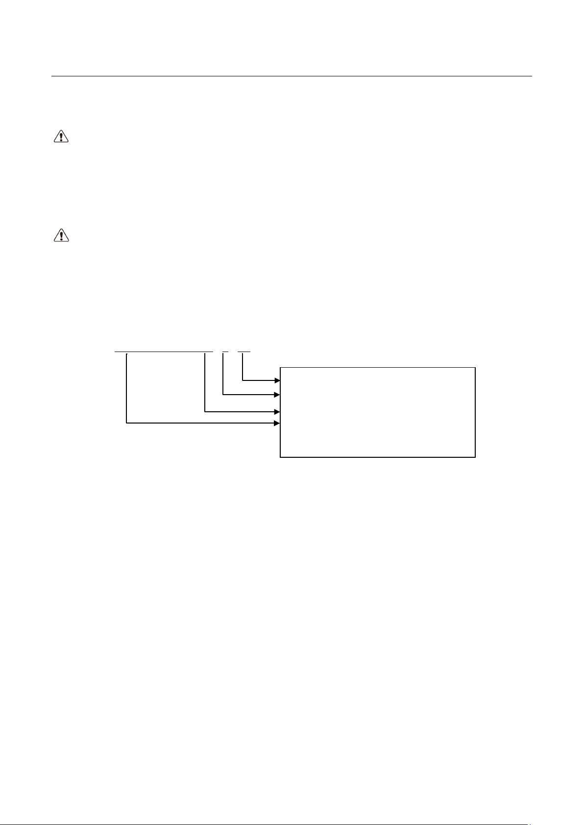
Z 15 + WITH TIMER .75 - 9 - 5.5
Maximum flow in US Gallons per Minute
Maximum Head in Feet
Size of pump inlet and outlet in inches
Pump Model: Z 15+ WITH TIMER OR
Z 15+ WITHOUT TIMER
1
Page 4
Z 15+ Circulation Pump
Version 05/2022
2
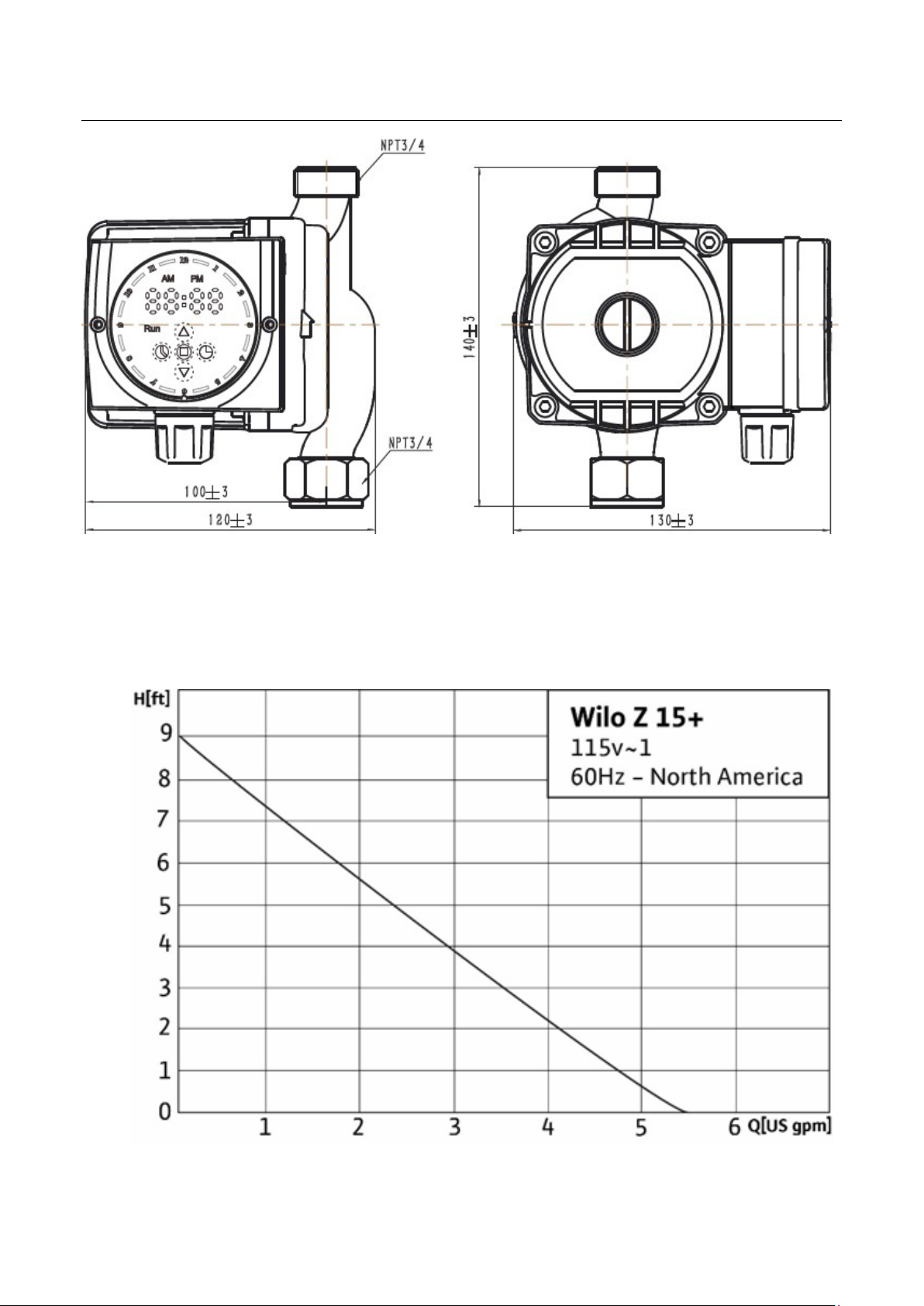
Product model: Z 15+
Maximum flow: 5.5 US Gallons per Minute
Rated voltage: 115V
Protection class: NEMA 12
Rated frequency: 60Hz
Maximum operating pressure: 145 PSI
2
Max. input power: 30W
Maximum water temperature: 160°F
1
Max. input current: 0.26A
Inlet thread: ¾” Female NPT
Max. Head: 9 Ft.
Low Lead Standard: NSF-61 Listed
Outlet thread: ¾” Male NPT
Pump Weight: 5.5 lbs
II. TECHNICAL PARAMETERS
Notes: 1. The minimum temperature of the water must be greater than 32°F, and the maximum temperature is
160°F.
2. The inlet (supply) pressure must be higher than .75 PSI to work properly.
Warning on Installation instructions
It is strongly suggested to hire a plumbing professional to install this pump into the hot-water
system.
III. INSTALLATION PRECAUTIONS
For best performance and reliability, please follow the instructions in this manual.
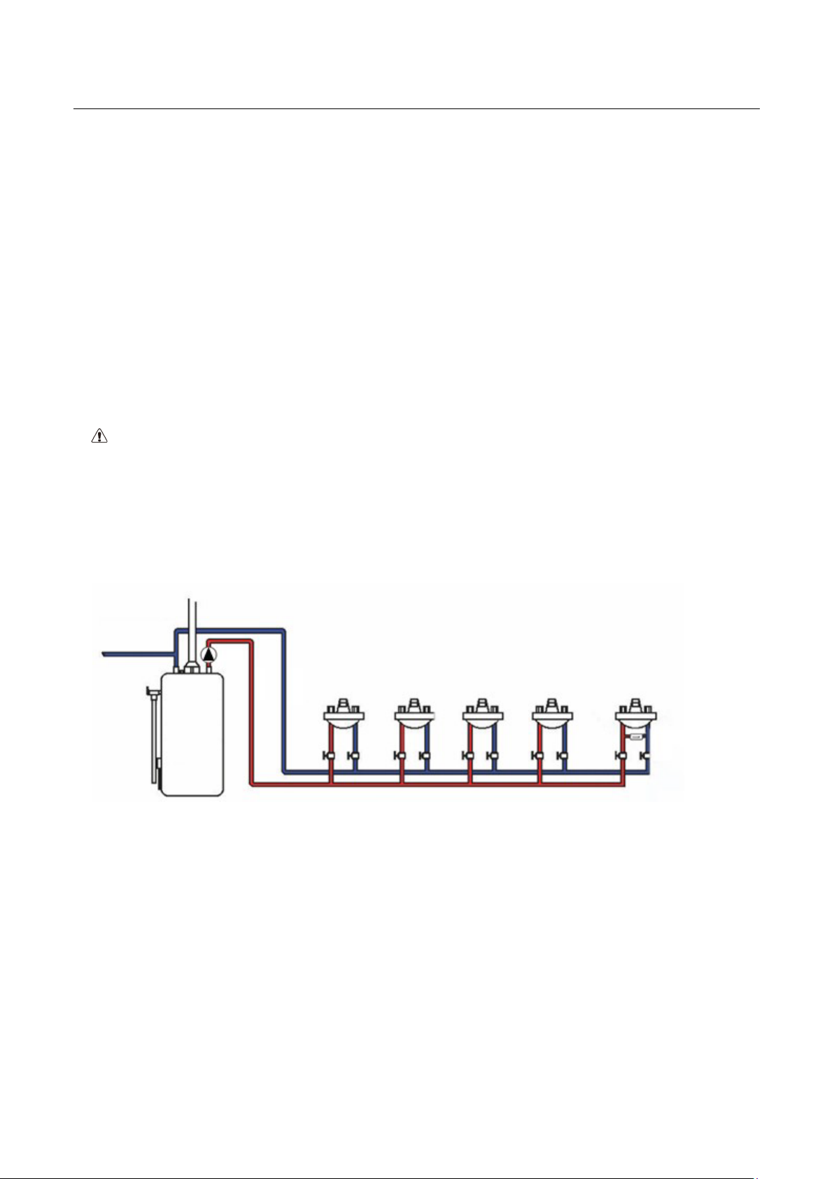
Water
pump
Hot
Cold
water
water
pipe
pipe
Temperature-sensing valve
Angle valve
Schematic diagram of a domestic hot water system
Step 1: Carefully check system components to ensure that the components are not missing or
damaged.
Scope of supply:
One circulating pump with, or without, timing function (provided by WILO)
One NSF-61 gasket to be placed into the union end of the pump (provided by WILO)
Installation and operation instructions (provided by WILO)
Page 5
Z 15+ Circulation Pump
Version 05/2022
3
Step 1: Close the gas valve or shut the power off to water heater.
Step 2: Close the supply water valve to the water heater located, in most cases, above the water heater on
the cold-water inlet to the hot water heater.
Step 3: Drain the water from the hot water pipes by opening a hot water faucet in the house (at the lowest
level), then open the hot water faucet at the highest level in the home to prevent a vacuum from
forming. Let the water drain until it stops flowing. Drain the remaining water from hot water heater
by opening the spigot (located at the bottom of the tank).
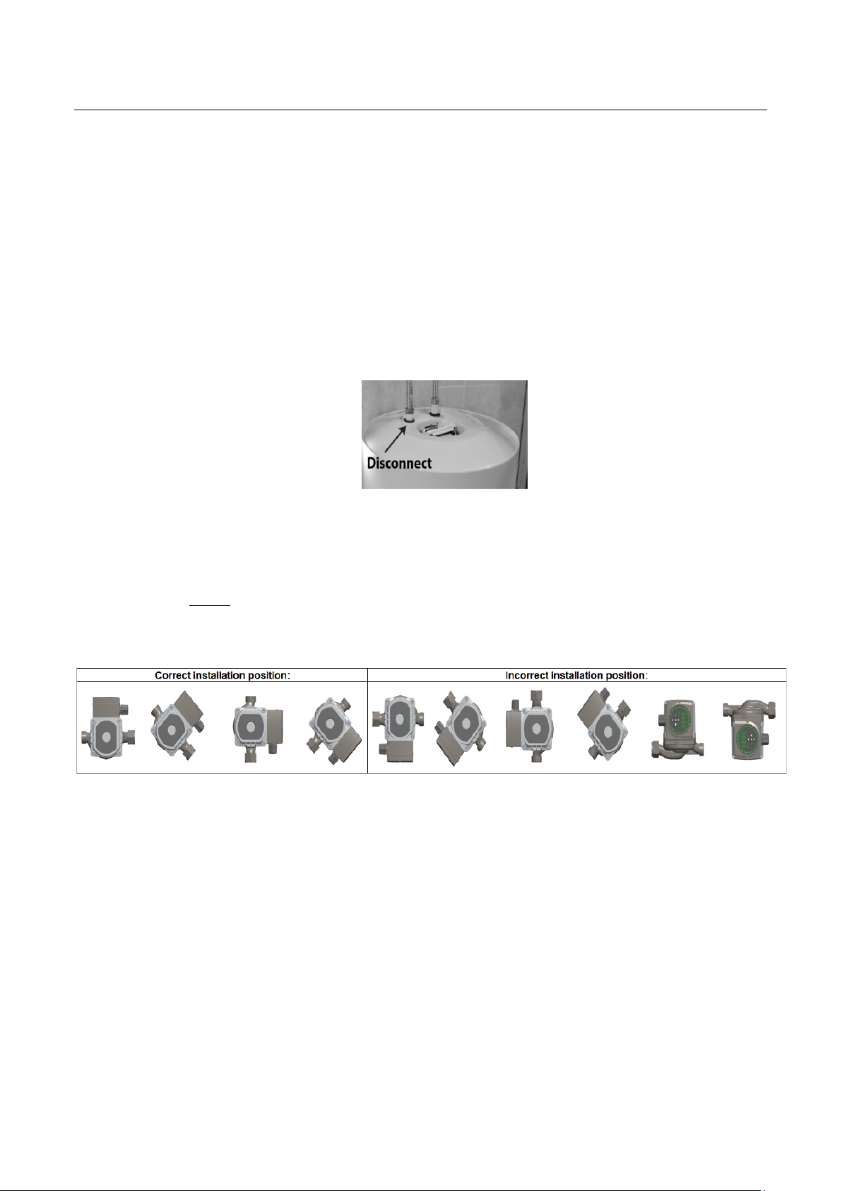
Step 4: Disconnect the hot water heater at the hot water discharge. (See below Picture).
Step 5: Using the supplied gasket, insert it into the 3/4" female union fitting and install the union end
into the water heater discharge line (the pump flow arrow on the side of the pump should be
installed so that the pump is pumping away from the hot water heater, toward the faucets).
Connect the water line (out to the faucets) to the 3/4" male NPT discharge of the pump and
tighten. NOTE: Do not overtighten the union connection! Be sure that the pump is not touching
the exhaust vent (chimney) of a gas or oil-fired hot water heater. It is recommended to place a
full-port ball valve upstream of the pump to be able to isolate the pump for servicing.
Step 6: Close faucet on the bottom of tank and lowest faucet in the house.
Step 7: Reopen the supply valve to the hot water heater and allow the water to run out of the faucet at
the highest level of the house until all the air has been completely purged from the piping.
Step 8: Shut the highest faucet off after all the air has been purged.
Step 9: Reopen Gas Valve / power to water heater and restart the water heater. Please refer to
manufacturer of the hot water boiler’s operation manual for specific instructions.
Step 10: Plug the electrical connection into a wall outlet.
Page 6
Z 15+ Circulation Pump
Version 05/2022
4
Performance parameters of the product
*Pump pictured with timer
Page 7
Z 15+ Circulation Pump
Version 05/2022
5
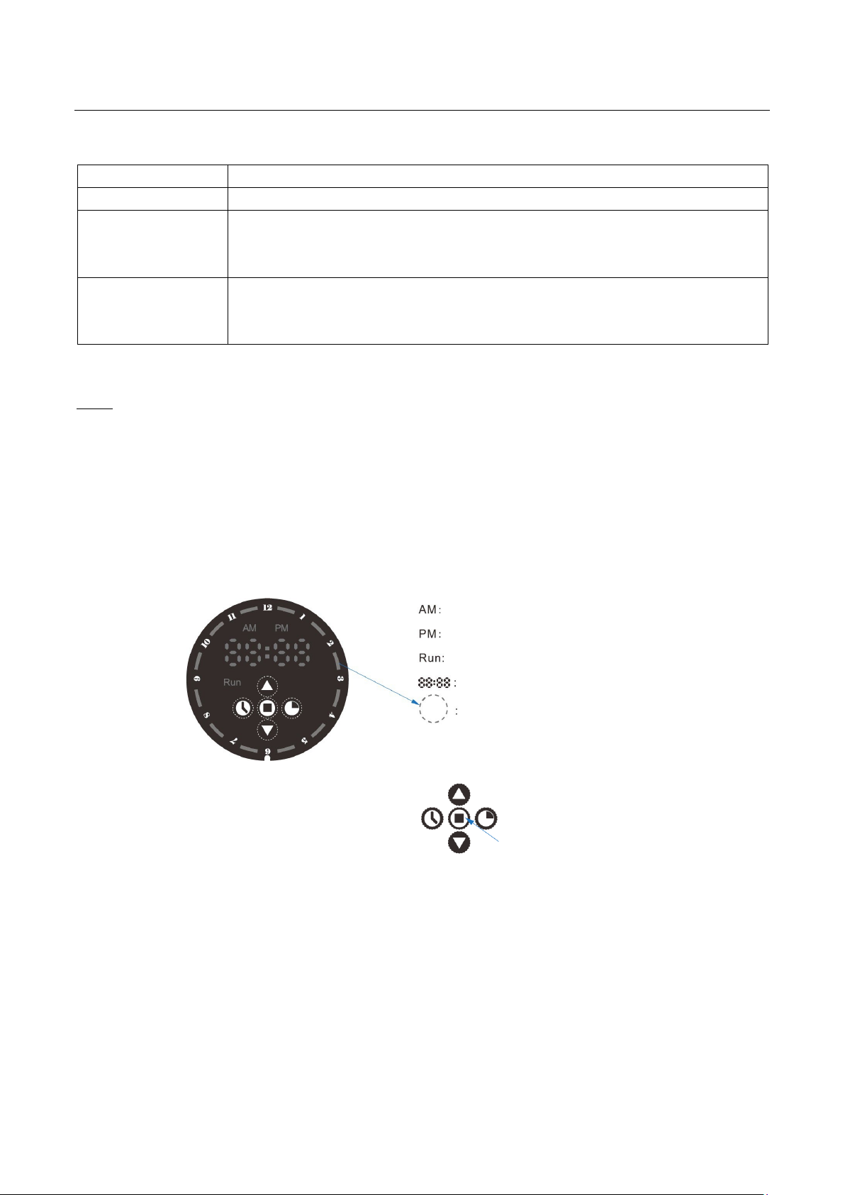
Forenoon indicator lamp
Afternoon indicator
Timing period
“+”
Time calibration
Timer calibration
Run
Function name
Function description
Forced operation
The water pump runs continuously.
Function overview
Timed operation
(applies to models
The water pump automatically runs during the set period of time. (The
minimum setting period of time is 1 hour in the timing function)
with timer only)
Screen function
(applies to models
with timer only)
From 9:00 p.m. to 7:00 a.m., the display interface of water pump will enter
the screen rest mode if not operated within 20s (except the running
indicator lamp), and can be lit by pressing any button.
Note: The factory default mode is that the pump is started at fixed time in 24h.
IV. HOW TO USE (applies to models with timer only; models without timer, skip to SECTION V. FAULT ANALYSIS AND ELIMINATION)
1. Panel description
Running indicator lamp
Clock
“-”
Page 8
6
2. Debugging and menu setting:
Special Note: The timer control is designed to turn the circulator on and off at preset times,
allowing the user to select operation of the circulator during high use periods of the day. If you
want to set the pump working over a specific time period (the timer programming), please
proceed to step 1. If you want the pump to work continuously and no timer needed, skip to
Step 3(Forced operation). In case of a power outage, the timer has a battery that helps keep
the time.
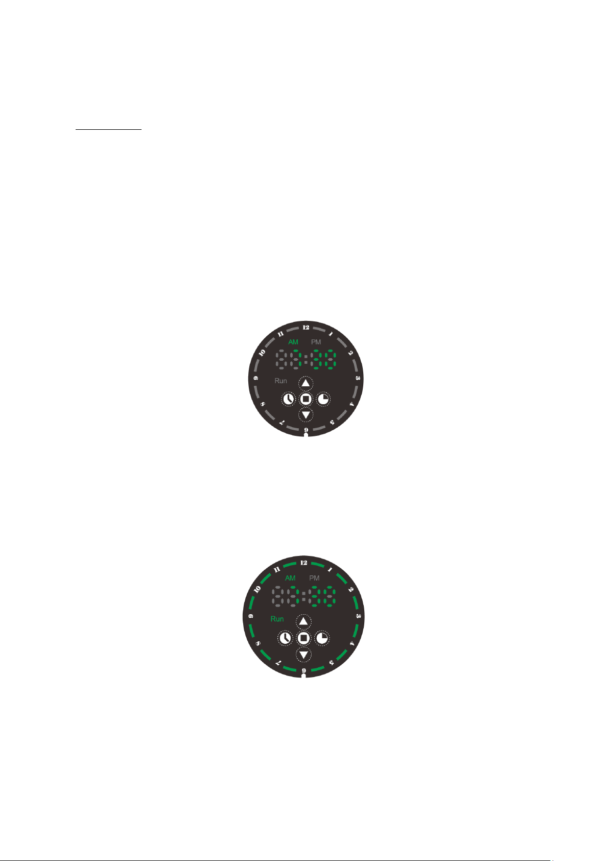
① Time calibration: The timer is based on the 24-hour system, and it automatically switches between
AM/PM when the hour digital lamp changes from 12 to 1 in the time calibration process. Adjust the time
of the pump to the current time; press the “Time calibration” key, the hour area starts flashing,
press the “+/-” key to adjust the hours; press the “Run” key to acknowledge. The minute area
will then flash, press the “+/-” key to adjust the minutes; exit the time calibration function by
pressing the “Run” key or not operating for 20s.
② Timer Calibration: Set the running period of the pump by pressing the “Timer calibration” key.
The dial indicator lamp will start flashing, and press the “+/-” key to adjust the cursor to the
target time period; (the timer is based on the 24-hour system, and it automatically switches
between AM/PM when the cursor passes through the 12 o’clock) Press the “Run” key to turn on
or off the current time period; exit the timer calibration function by pressing the “Timer
calibration” key or not operating for 20s.
Page 9
7
Fault
Main causes
Elimination methods
The cold-water pipe is
filled with hot water
The temperature sensing function of the jet
valve has failed
Add the number of jet valves
needed
Forgot to open the cold/hot water angle valve
at the connection of the jet valve
The non-return function of the jet valve has
failed
The pump does not run
The current set time is not turned on
Turn on the current set time
The time returns to zero
powered off
WILO USA LLC
www.wilo-
usa.com
Wilo Canada Inc.
www.wilo-
canada.com
Wilo Mexico
www.wilo-
mexico.com
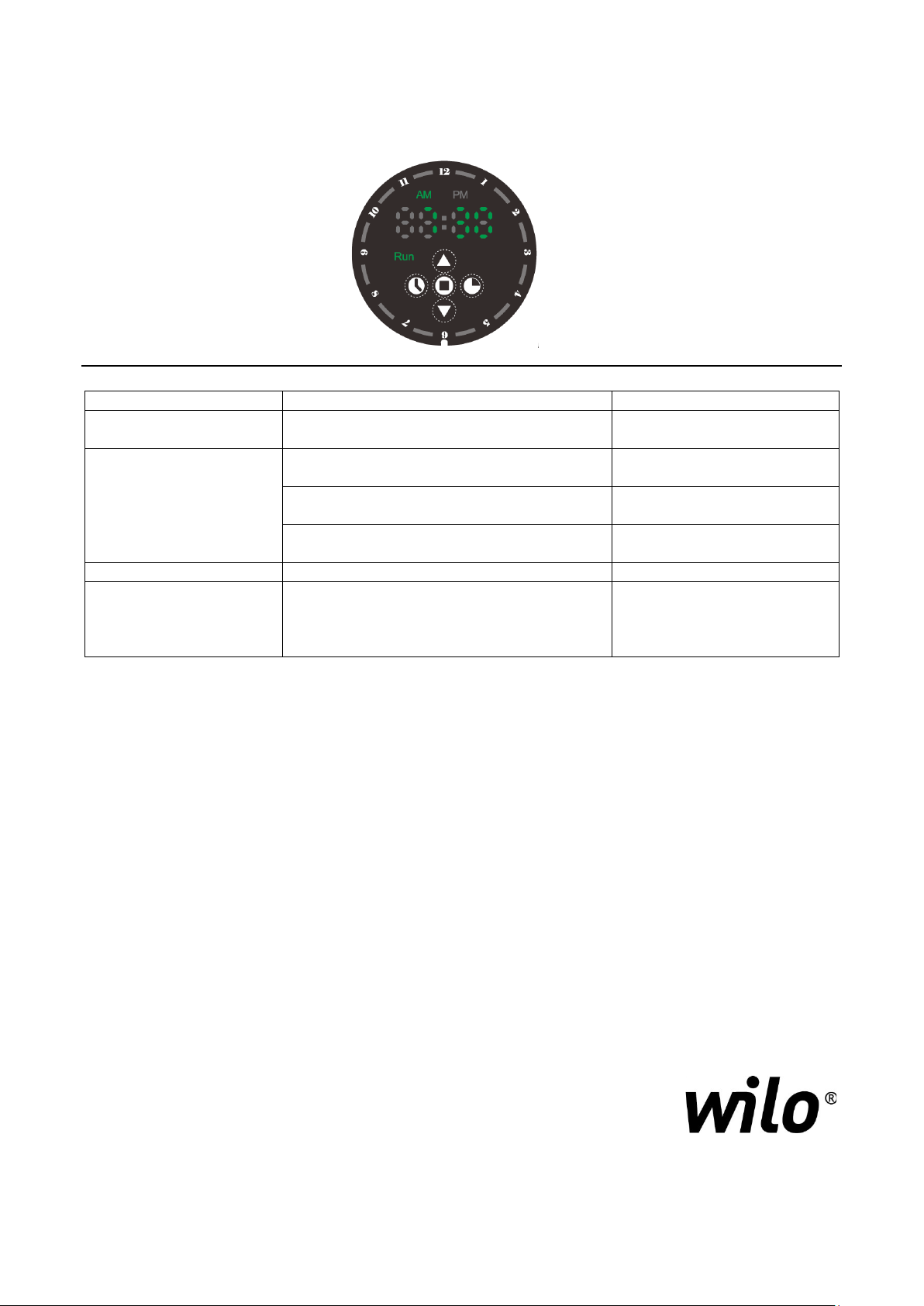
③ Forced operation: Press the “Run” key, the set time goes off, and the pump runs automatically
and continuously.
I. FAULT ANALYSIS AND ELIMINATION
The water from the hot
water side of the faucet is
not hot
when the pump is
The built-in button battery of pump is
powered on after it is
There are branch pipes
exhausted
END OF SECTION
Replace the jet valve
Open the angle valve
Replace the jet valve
Calibrate the time manually
262-204-6600
403-276-9456
+52 442 167 00 32
 Loading...