

Wilo TM, TMW, TM 32/7, TM 32/8, TMW 32/8 Installation And Operating Instructions Manual
...Page 1

Page 2
Page 3
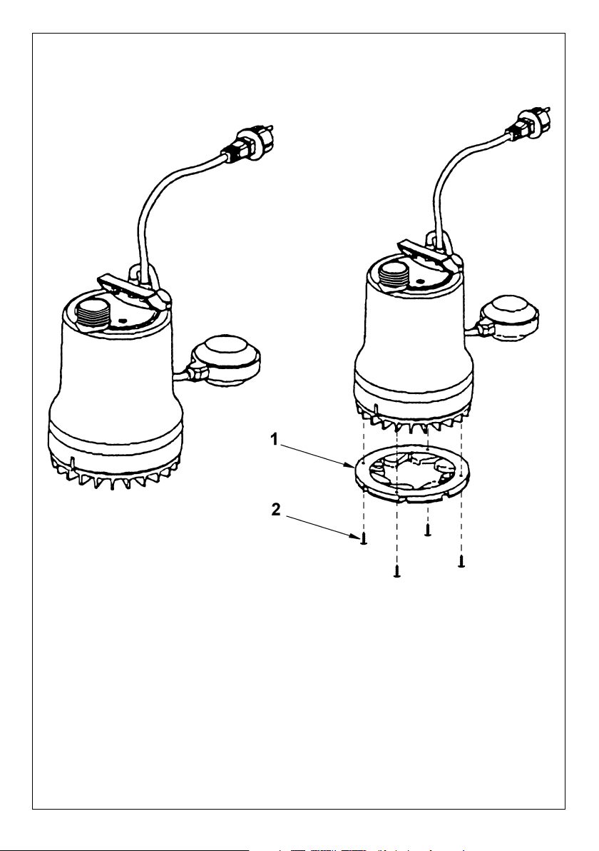
Fig. 2
Page 4

CE-Konformitätserklärung . . . . . . . . . . . . . . 1-2
1. Allgemeines . . . . . . . . . . . . . . . . . . . . . . . 3
2. Sicherheit . . . . . . . . . . . . . . . . . . . . . . . . 4
3. Transport und Zwischenlagerung . . . . . . . 5
4. Beschreibung von Erzeugnis
und Zubehör . . . . . . . . . . . . . . . . . . . . . . 5
5. Aufstellung/Einbau . . . . . . . . . . . . . . . . . . 6
6. Inbetriebnahme . . . . . . . . . . . . . . . . . . . . 7
7. Wartung . . . . . . . . . . . . . . . . . . . . . . . . . . 7
8. Störungen, Ursachen und Beseitigung . . . 8
9. Demontage und Montage . . . . . . . . . . . . 9
D
EC declaration of conformity . . . . . . . . . . . . 1-2
1. General Information . . . . . . . . . . . . . . . . . 10
2. Safety . . . . . . . . . . . . . . . . . . . . . . . . . . . 11
3. Transport and interim storage . . . . . . . . . 12
4. Product and accessory
description . . . . . . . . . . . . . . . . . . . . . . . . 12
5. Assembly/Installation . . . . . . . . . . . . . . . . 13
6. Operation . . . . . . . . . . . . . . . . . . . . . . . . 13
7. Maintenance. . . . . . . . . . . . . . . . . . . . . . . 14
8. Problems, Causes and Remedies . . . . . . 15
9. Disassembly and assembly . . . . . . . . . . . 16
GB
Déclaration de conformité CE . . . . . . . . . . . 1-2
1. Généralités . . . . . . . . . . . . . . . . . . . . . . . 17
2. Sécurité . . . . . . . . . . . . . . . . . . . . . . . . . . 18
3. Transport et stockage avant utilisation . . . 19
4. Description du produit et de
ses accessoires . . . . . . . . . . . . . . . . . . . . 19
5. Installation/Montage . . . . . . . . . . . . . . . . . 20
6. Mise en service . . . . . . . . . . . . . . . . . . . . 21
7. Entretien. . . . . . . . . . . . . . . . . . . . . . . . . . 21
8. Pannes, causes et remèdes . . . . . . . . . . . 22
9. Démontage et montage . . . . . . . . . . . . . . 23
F
Dichiarazione di conformità CE . . . . . . . . . . 1-2
1. Generalità . . . . . . . . . . . . . . . . . . . . . . . . 24
2. Sicurezza . . . . . . . . . . . . . . . . . . . . . . . . . 25
3. Trasporto e magazzinaggio . . . . . . . . . . . 26
4. Descrizione del prodotto
e degli accessori . . . . . . . . . . . . . . . . . . . 26
5. Installazione/montaggio . . . . . . . . . . . . . . 27
6. Messa in esercizio . . . . . . . . . . . . . . . . . . 28
7. Manutenzione. . . . . . . . . . . . . . . . . . . . . . 28
8. Blocchi, cause e rimedi . . . . . . . . . . . . . . 29
9. Smontaggio e montaggio . . . . . . . . . . . . 30
I
Page 5

1
D CE-Konformitäts-
erklärung
Hiermit erklären wir, daß
dieses Aggregat folgenden
einschlägigen Bestimmungen
entspricht:
EG-Maschinenrichtlinien
89/392/EWG i.d.F.,
91/368/EWG, 93/44/EWG,
93/68/EWG
Elektromagnetische
Verträglichkeit
89/336/EWG i.d.F.
92/31/EWG, 93/68/EWG
Angewendete harmonisierte
Normen, insbesondere
EN 809, EN 50 081-1,
EN 50 082-1, EN 50 081-2,
EN 50 082-2.
GB EC declaration of
conformity
We hereby declare that this
unit complies with the
following relevant provisions:
EC machinery directive
89/392/EWG in this version,
91/368/EWG, 93/44/EWG,
93/68/EWG
Resistance to
electromagnetism
89/336/EWG in this version
92/31/EWG, 93/68/EWG
Applied harmonized
standards in particular:
EN 809, EN 50 081-1,
EN 50 082-1, EN 50 081-2,
EN 50 082-2.
F
Déclaration de
conformité CE
Par la présente, nous
déclarons que cet
agrégat sitisfait aux
dispositions suivantes:
Directives CEE relatives
aux machines 89/392/CEE,
91/368/CEE, 93/44/CEE,
93/68/CEE
Compatibilité
électromagnétique
89/336/CEE, 92/31/CEE,
93/68/CEE
Normes utilisées
harmonisées, notamment
EN 809, EN 50 081-1,
EN 50 082-1, EN 50 081-2,
EN 50 082-2.
NL EG-verklaring van
overeenstemming
iermede verklaren wij dat
deze machine voldoet aan
de volgende bepalingen:
EG-richtlijnen betreffende
machines 89/392/EEG,
91/368/EEG, 93/44/EEG,
93/68/EEG
Elektromagnetische
tolerantie
89/336/EEG, 92/31/EEG,
93/68/EEG
Gebruikte geharmoniseerde
normen, in het bijzonder
EN 809, EN 50 081-1,
EN 50 082-1, EN 50 081-2,
EN 50 082-2.
E Declaración de
conformidad CE
Por la presente declaramos
que esta unidad satisface las
disposiciones pertinentes
siguientes:
Directivas CE sobre
máquinas 89/392/CEE,
91/368/CEE, 93/44/CEE,
93/68/CEE
Compatibilidad electromagnética 89/336/CEE,
92/31/CEE, 93/68/CEE
Normas armonizadas
utilizadas particularmente
EN 809, EN 50 081-1,
EN 50 082-1, EN 50 081-2,
EN 50 082-2.
I Dichiarazione di
conformità CE
Con la presente si dichiara
che le presenti pompe sono
conformi alle seguenti
direttive di armonizzazione
Direttiva Macchine CEE
89/392/CEE, 91/368/CEE,
93/44/CEE, 93/68/CEE
Compatibilità
elettromagnetica
89/336/CEE, 92/31/CEE,
93/68/CEE
Norme armonizzate
applicate, in particolare
EN 809, EN 50 081-1,
EN 50 082-1, EN 50 081-2,
EN 50 082-2.
SF CE-standardinmukai-
suusseloste
Ilmoitamme täten, että tämä
laite vastaa seuraavia
asiaankuuluvia määräyksiä:
EY-konedirektiivit
89/392/ETY, 91/368/ETY,
93/44/ETY, 93/68/ETY
Sähkömagneettinen
soveltuvuus
89/336/ETY, 92/31/ETY,
93/68/ETY
Käytetyt yhteensovitetut
standardit, erityisesti
EN 809, EN 50 081-1,
EN 50 082-1, EN 50 081-2,
EN 50 082-2.
S EEC konformitets-
deklaration
Härmed förklaras att denna
maskin uppfyller följande
bestämmelser:
EEC maskindirektiv
89/392/EEC i denna version,
91/368/EEC, 93/44/EEC,
93/68/EEC
Elektromagnetisk
kompatibilitet 89/336/EEC i
denna version, 92/31/EEC,
93/68/EEC
Tillämpade harmoniserade
normer, särskilt:
EN 809, EN 50 081-1,
EN 50 082-1, EN 50 081-2,
EN 50 082-2.
H EK. azonossági
nyilatkozat
Ezennel kijelentjük, hogy
az agregát a megkívánt
alanti feltételeknek
megfelel:
EK-Gépirányelvek
89/392/EWG, 91/368/EWG,
93/44/EWG, 93/68/EWG
Elektromagnetikus
ÖsszeegyeztethetŒség
89/336/EWG, 92/31/EWG,
93/68/EWG
Alkalmazott, harmonizált
normák, különösen az
EN 809, EN 50 081-1,
EN 50 082-1, EN 50 081-2,
EN 50 082-2.
Page 6

Quality Management
2
TR Uygunluk Belgesi
As¸agˇí´daki cihazlarí´n
takibi standartlara vygun
oldugˇunu temin
ederiz:
AB-Makina Standartlari
89/392/EWG i.d.F.,
91/368/EWG, 93/44/EWG,
93/68/EWG
Elektromanyetik
Uyumluluk
89/336/EWG i.d.F.,
92/31/EWG, 93/68/EWG
Özellikle kullaní´lan Normlar
EN 809, EN 50 081-1,
EN 50 082-1, EN 50 081-2,
EN 50 082-2.
GR ∆ήλωση συµµρφωσης
µε τους κανονισµούς CE
∆ηλώνουµε τι το προϊν
αυτ ικανοποιεί τις
ακλουθες διατάξεις:
Οδηγίες CEE σχετικά
µε µηχανήµατα
89/392/CEE, 91/368/CEE,
93/44/CEE, 93/68/CEE
Ηλεκτροµαγνητική
συµβαττητα
89/336/CEE, 92/31/CEE,
93/68/CEE
Εναρµονισµένα
χρησιµοποιούµενα
πρτυπα, ιδιαίτερα
EN 809, EN 50 081-1,
EN 50 082-1, EN 50 081-2,
EN 50 082-2.
CZ Osvûdãení o shodnosti s
normami EU
Prohla‰ujeme tímto, Ïe toto
zafiízení odpovídá následujícím
pfiíslu‰n˘m ustanovením:
Smûrnice o strojírenském
zafiízení ES 89/392/EHS
vãetnû dodatkÛ,
91/368/EHS, 93/44/EHS,
93/68/EHS
Elektromagneticá sná‰enlivost 89/336/EHS vãetnû
dodatkÛ, 92/31/EHS,
93/68/EHS
PouÏité souhlasné normy,
zejména:
EN 809, EN 50 081-1,
EN 50 082-1, EN 50 081-2,
EN 50 082-2.
PL OÊwiadczenie zgodnoÊci EC
Niniejszym oÊwiadczamy, ˝e
pompa odpowiada nast´pujàcym w∏aÊciwym dla niej
dyrektywom:
Wytyczne dla przemys∏u
maszynowego EC
89/392/EEC w tej wersji,
91/368/EEC, 94/44/EEC,
93/68/EEC
OdpornoÊç elektromagnetyczna EC
89/336/EEC w tej wersji,
92/31/EEC, 93/68/EEC
Zastosowano normy
zharmonizowane, w
szczególnoÊci:
EN 809, EN 50 081-1,
EN 50 082-1, EN 50 081-2,
EN 50 082-2.
RUS
Zaåvlenie o sootvetstvii
normam, dejstvuœwim v
Evropejskom Soobwestve
Nastoåwim dokumentom
zaåvlåem, hto dannaå
ustanovka sootvetstvuet
sleduœwim postanovleniåm:
Direktivy ES
otnositelæno maπin i
stankov 89/392/CEE,
91/368/CEE, 93/44/CEE,
93/68/CEE
Qlektromagnitnaå
sovmestimostæ
89/336/CEE, 92/31/CEE,
93/68/CEE
Ispolæzovavπieså
garmonizirovannye
standarty i normy, v
hastnosti EN 809,
EN 50 081-1, EN 50 082-1,
EN 50 081-2, EN 50 082-2.
DK EF-overensstemmelses-
erklæring
Det erklæres hermed, at dette
udstyr er i overens-stemmelse
med følgende bestemmelser:
EU maskindirektiver:
89/392/EØF i denne
udgave, 91/368/EØF,
93/44/EØF, 93/68/EØF
Elektromagnetisk
kompatibilitet:
89/336/EØF i denne
udgave, 92/31/EØF,
93/68/EØF
Anvendte harmoniserede
normer, især:
EN 809, EN 50 081-1,
EN 50 082-1, EN 50 081-2,
EN 50 082-2.
N EU-overensstemmelses-
erklæring
Det erklæres herved at
dette utstyret stemmer
overens med følgende
bestemmelser:
EU-direktiver for maskiner
89/392/EEC og følgende,
91/368/EEC, 93/44/EEC,
93/68/EEC
Elektromagnetisk
kompatibilitet
89/336/EEC og følgende,
92/31/EEC, 93/68/EEC
Anvendte harmoniserte
normer, i særdeleshet
EN 809, EN 50 081-1,
EN 50 082-1, EN 50 081-2,
EN 50 082-2.
WILO AG
Nortkirchenstraße 100
44263 Dortmund · Germany
2011678.3
Page 7
10
ENGLISH
1. General Information
Installation and service by qualified
personnel only!
1.1 Uses
The dewatering and dirty water submersible motordriven pumps are used to automatically drain pits
and shafts, to keep dry yards and cellars that are
regularly under flood alert, to lower surface water,
provided the waste water cannot drain into the
sewage system due to the natural gradient.
The pumps are suitable for the conveyance of
mildly polluted water, rain water and wash water.
Type TMW 32/11 HD is suitable for the conveyance
of aggressive media, such as swimming pool water
and condensate.
The pumps are not suitable for water with coarse
impurities such as sand, fibres or faeces, explosive
liquids or for use in potentially explosive areas.
The pumps can be installed permanently or so as to
be transportable.
Submersible motor-driven pumps with less than 10 m
of connecting cable are (to EN 60335)
only
permitted for use within buildings
, in other words
not in the open air.
The pump must not be used for
pumping
drinking water.
The pump may not be used to drain
swimming pools if people are in the
water
.
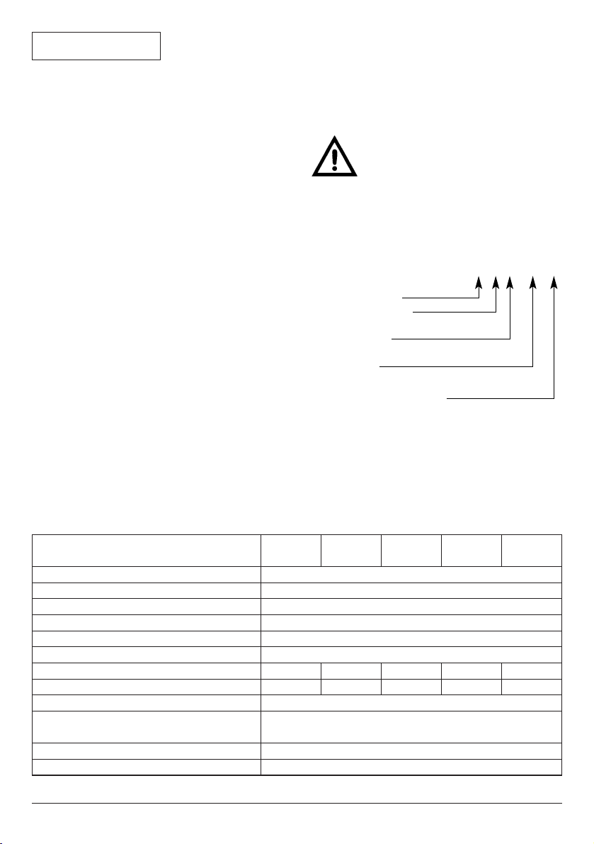
1.2 Product data
1.2.1 Rating plate
TM W 32 / 81HD
TM W 32 / 11 HD
Submersible pump
w = with whirl device
Nominal width of
drain connection
Maximum pump lift [m]
for Q = 0 m
3
/h
HD = for aggressive media
(material 1.4435 (AISI 316L)
1.2.2 Connection and electrical data
TM
32/7
TM
32/8
TMW
32/8
TMW
32/11
TMW
32/11 HD
Power consumption P1[kW]
Nominal current 1~230 V [A]
Speed [
1
/min]
Protection class at max. immersion depth
Insulation class
Max. noise level at min. level
Volume rate of flow Qmax. [m
3
/h]
Pump lift Hmax. [m]
Immersion depth (
B–) max. [m]
Size of grains or solids [mm]
Density of flow medium max. [kg/m
3
]
Max. temperature ofmaterial tobe conveyed[°C]
short-term up to 3 minutes
see rating plate
see rating plate
2900
IP 68
F
55 dbA
10
3
35
90
7 10101515
7 8 7/8 10/11 10/11
Page 8
2. Safety
These instructions contain important information
which must be followed when installing and
operating the pump. These operating instructions
must therefore be read before assembly and
commissioning by the installer and the responsible
operator. Both the general safety instructions in
the “Safety precautions” section and those in
subsequent sections indicated by danger symbols
should be carefully observed.
2.1 Danger symbols used in these operating
instructions
Safety precautions in these operating instructions
which, if not followed, could cause personal injury
are indicated by the symbol:
when warning of electrical voltage with
The following symbol is used to indicate that by
ignoring the relevant safety instructions, damage
could be caused to the pump/machinery and its
functions:
2.2 Staff training
The personnel installing the pump must have the
appropriate qualifications for this work.
2.3 Risks incurred by failure to comply with the
safety precautions
Failure to comply with the safety precautions could
result in personal injury or damage to the pump or
installation. Failure to comply with the safety
precautions could also invalidate any claim for
damages.
In particular, lack of care may lead to problems
such as:
– Failure of important pump or machinery functions,
– Personal injury due to electrical, mechanical and
bacteriological causes.
2.4 Safety precautions for the operator
Existing regulations for the prevention of accidents
must be followed.
ATTENTION!
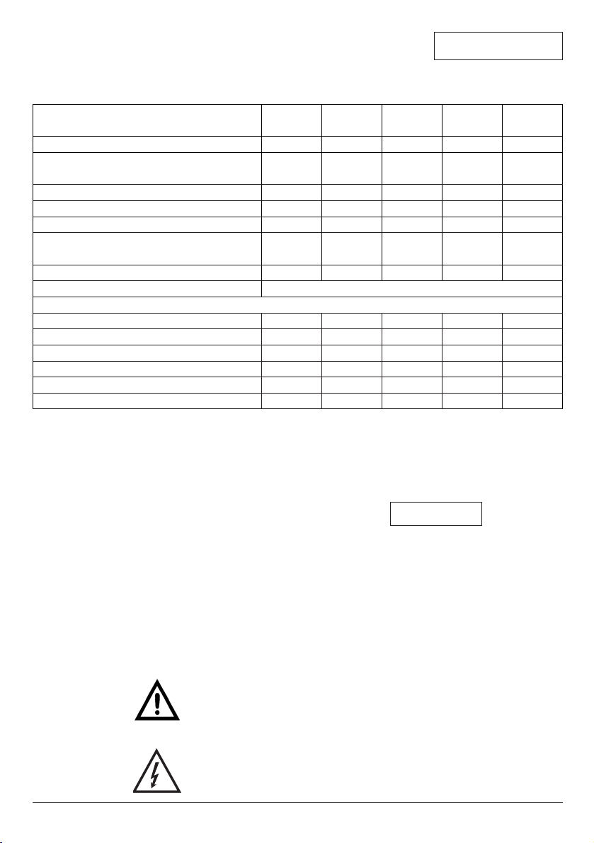
TM
32/7Equipment
TM
32/8
TMW
32/8
TMW
32/11
TMW
32/11 HD
Cable type
Cable length [m] / plug
Float switch connected
Whirl device
Non-return device integrated
Overall height L [mm] (up to connection)
Diameter of pump D [mm]
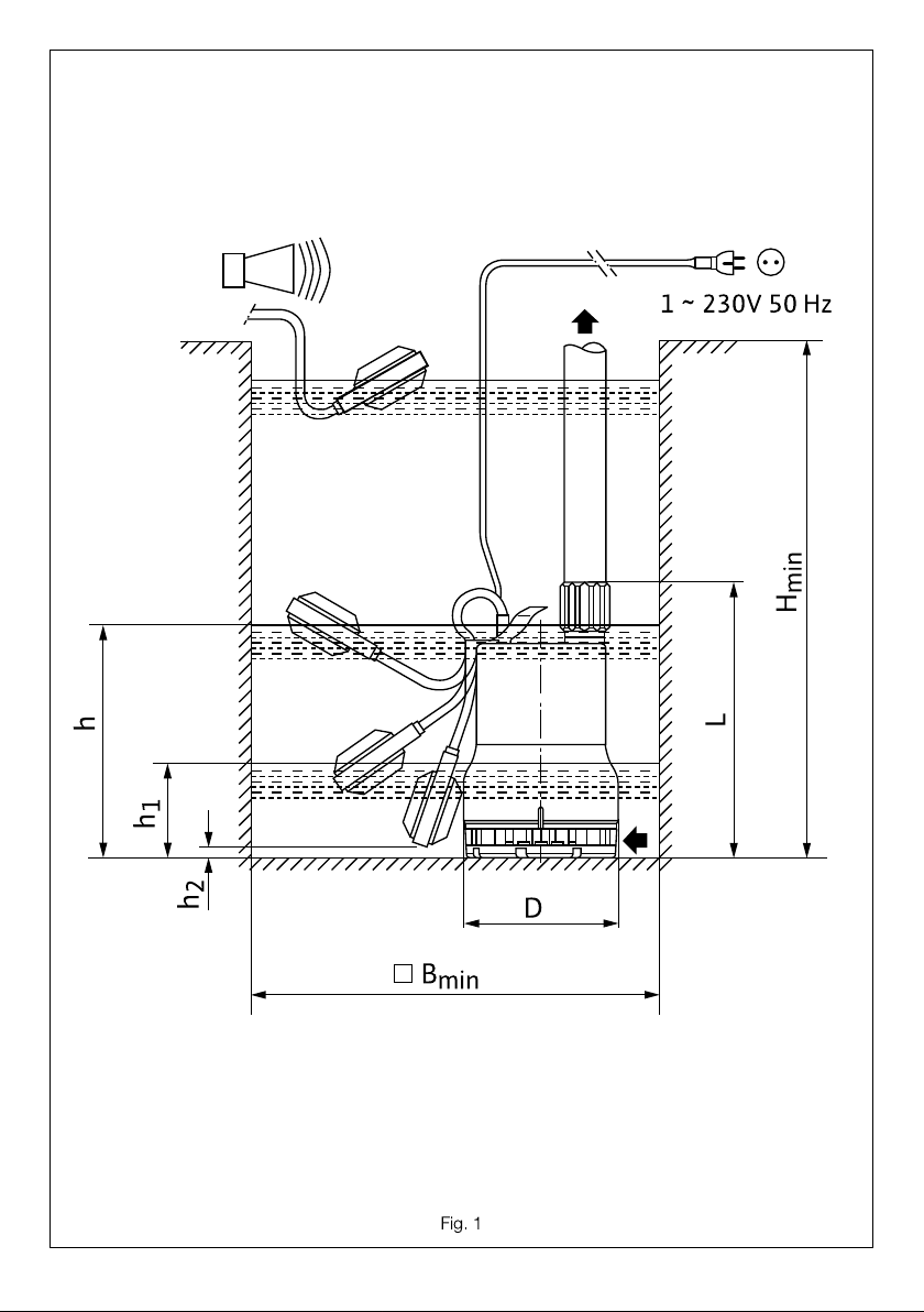
Level control (fig. 1)
Shaft dimensions Hmin [mm]
Y Bmin [mm]
Max. Start-up level h ± 8 [mm]
Min. Cut-out level h1
± 8 [mm]
Min. Float level h2 [mm]
Pressure support DN: Pipe connection
Hose connection [mm]
H05RNF
3 / earthing
contact
10/earthing
contact
–
–
–
3 / earthing
contact
3 / earthing
contact
10/earthing
contact
H07RNF H05RNF H05RNF H07RNF
xx
x
x
x
x
x
x
x
x
–
–
–
l 35
–
l 35
Rp 1
&
–
Rp 1
&
–
Rp 1
&
–
294
280
350 x 350
237
50
14
–
–
–
–
–
280
350 x 350
250
50
14
330
350 x 350
280
50
14
330
350 x 350
280
50
14
294 293 323 323
165
When ordering spare parts, please give all the information on the pump rating plate.
11
ENGLISH
,
Min. drainage level h1
± 8 [mm]
18 18 30 30 30
Page 9

12
ENGLISH
Dangers caused by electrical energy are to be
excluded. Directives issued by the VDE [German
Association of Electrical Engineers] and the local
electricity supply companies are to be observed.
2.5 Safety information for inspection
and assembly
The operator is responsible for ensuring that
inspection and assembly are carried out by
authorised and qualified personnel who have
studied the operating instructions closely.
Work on the pump/machinery should only be carried
out when the machine has been brought to a
standstill.
2.6 Unauthorized modification and manufacture
of spare parts
Alterations to the pump or installation may only be
carried out with the manufacturer’s consent. The use
of original spare parts and accessories authorised
by the manufacturer will ensure safety. The use of
any other parts may invalidate claims invoking the
liability of the manufacturer for any consequences.
2.7 Unauthorised operating methods
The operating safety of the pump or installation
supplied can only be guaranteed if it is used in
accordance with paragraph 1 of the operating
instructions. The limiting values given in the
catalogue or data sheet must neither be exceeded
nor allowed to fall below those specified.
3. Transport and interim storage
The pump may only be transported/suspended on the handle
provided for transport. It is to be
protected against mechanical damage
and may not be exposed to temperatures outside the range 0 °C to +50°C.
4. Product and accessory
description
4.1 Pump description
The housing of the submersible motor-driven pump
is made of plastics. The electric motor is protected
against the pump chamber by a shaft seal ring to
seal off the Motor against oil chamber and a
mechanical seal to seal off the oil chamber against
water.
The motor is cooled by the surrounding pumping
medium.
The pump is mounted on the bottom of a shaft.
The water is pumped into the channel a hose or
a permanently installed pipe. The pumps of series
TM / TMW operate automatically by means of a float
switch which switches the pump on at a specific
water level “h” (fig. 1) and off at a minimum water
level “h1”.
Do not allow the pump to run dry.
Dry running destroys the mechanical
seal between pump and motor.
Maintain minimum water level “h1”
(see table 1.2.2 and fig. 1)!
The AC motors are equipped with a built-in
motor
cut-out, which switches the motor off if it overloads
and automatically switches it back on again once it
has cooled down.
The pumps have a vent hole between the bottom
and top pump sections, so that during operation
water (air) escapes through the slit in the suction
strainer. This bypass prevents air from collecting
underneath the flap trap, thereby guaranteeing the
operational safety of the pump.
TMW: The pumps are equipped with built-in non-
return devices.
For waste water with suspended and
settlable solids, the submersible motordriven pump was fitted with a whirl
device on the suction strainer. Precipitating
impurities are constantly whirled up in the
suction area of the pump and pumped out
with the water. This largely prevents the
pump shaft from silting up with all the
unfavourable consequences such as pump
blockages and bad smells.
TM: TM pumps are not equipped with whirl
device and non-return device.
The individual equipment variations can be found in
the table under 1.2.2.
The pumps are operated by connecting the
earthing-pin plug.
If the dirty water drain does not permit interruption,
a 2ndpump (automatic reserve pump) in connection
with the required switchbox (accessory) increases
operational safety if there is a fault in the 1
st
pump.
ATTENTION!
ATTENTION!
Page 10
4.2 Products delivered
– Submersible motor-driven pump complete,
– Installation and operating instructions.
4.3 Accessories
Accessories must be ordered separately.
– Non-return device Rp 1& with drain valve
– ER 1-A switchbox for the automatic transmitter-
dependent control of a submersible motor-driven
pump up to motor power P
2
= 3 kW,
– SK 530 switchbox for the automatic transmitter-
dependent control of two submersible motordriven pumps up to motor power P
2
= 3 kW,
– Small alarm switching device KAS, off-line,
– Alarm switching device DrainAlarm 2, off-line.
5. Assembly/Installation
5.1 Assembly
– Site and shaft for the pump must be frost-free.
– In the case of permanent installation the bottom
of the shaft must be level and free from coarse
impurities (e.g. rubble, earth).
The pump may not be carried or
hung by the connecting cable or
float. A rope should be used to lower
and locate the pump.
– The diameter of the compressed-air piping (pipe /
hose connection) may not be smaller than the
delivery connection of the pump. To avoid
pressure losses, it is recommended to select a
nominal width greater for the pipe connection.
– To protect against possible reflux from the public
conduit the compressed-air piping is to be fed
over the locally established reflux level (generally
street level) in a bend.
– If the TM pump is permanently installed, a non-
return device (accessory) is required.
– The pipe connections to the pressure pipe
connections of the pump are to be sealed with
Teflon tape.
Constant leaks in this area may
destroy the built-in non-return
device and screw joint.
– The pump is designed such that it can be fully
submerged in the pumping medium. The level
control for the start-up / cut-out level can be
altered via the free float cable.
The minimum level (see fig. 1 and
table 1.2.2) may not be fallen short of.
5.2 Electrical connection
Electrical connection should be made
by a qualified electrician. Current
national regulations must be observed
(e.g. VDE regulations in Germany).
– Check the mains current and voltage.
– Ensure compliance with the data on the rating
plate.
– Mains voltage see rating plate.
– Mains fuse: 10 A, time-lag.
– Observe earthing regulations.
– It is recommended that a
residual current
operating device
to be provided by the
customer be installed for a tripping current of
30 mA (for installation in open air directive!).
– The pump is connected to a socket outlet with
earthing contact, to be provided by the customer.
To connect the pump to a switching device the
earthing-pin plug is cut and the connecting cable
wired as follows:
brown wire to “
L1”, blue wire to “N”, yellow-green
wire to “
PE”.
– The socket outlet and /or switchbox are to be
installed so as to be flood-proof and in a dry
area.
– Pumps intended for use in or on swimming pools,
garden ponds and similar places must have a
supply cable to the mains which is no lighter than
rubber-insulated flexible cables with identification
symbol H07 RN-F (245 IEC 66) to EN 60335.
– In accordance with EN 60335, submersible
motor-driven pumps with less than 10 m of
connecting cable are only permitted for use within
buildings, in other words not for operation in the
open air.
6. Operation
The pump may not be used to drain
swimming pools if
people are in the
water.
6.1 Setting the pump
– The unhindered movement of the float switch must
be guaranteed at all costs. The switch must switch
the pump off before the pump’s suction openings
can draw in air. See table for minimum water level.
ATTENTION!
ATTENTION!
ATTENTION!
13
ENGLISH
Page 11

14
ENGLISH
– After the shaft has been filled and the shut-off
valve on the pressure side opened (if available),
the pump starts up automatically if the switching
level “h” is reached and cuts out as soon as the
cut-out level “h1” responds.
Do not allow the pump to run dry.
– Switching level adjustment of the float switch
The switching level (start-up point) can be altered
via the free float cable by moving the cable within
the retaining eye.
The fault-free operation of the level control is
guaranteed if the data given in table 1.2.2 and
fig. 1 are observed.
A small degree of water penetration (lateral slit
between suction strainer and housing) when level
“h2” is reached is normal and necessary to
ensure the operational safety of the pump.
– Do not direct the jet of water to be fed into the
shaft at the suction strainer of the pump.
Entrained air can prevent the operating pump
from functioning if the vent hole in the housing is
blocked.
– The maximum quantity of water feeding into the
shaft may not exceed the pump’s capacity.
Monitor the shaft during commissioning.
– To increase the required capacity (by approx.
16% of the delivery head) the whirl device system
of the TMW pumps can be shut down as follows
(fig. 2):
– Pull the mains plug,
– Remove pump from the shaft,
– Remove the 4 screws (pos. 2) below the
suction basket,
– Remove the whirl device (pos. 1), rotate by 180°
and secure again with the 4 screws,
– lower pump again and start up.
7. Maintenance
Pull the mains plug before checking
the pump!
The pump is almost maintenance free.
To prevent the pump from becoming blocked due
to long periods of inactivity, its performance
reliability should be checked at regular intervals
(every 2 months) by lifting the float out manually and
running the pump for a short period.
A small amount of wear on the shaft sealing ring
and the mechanical seal is unavoidable and is
accelerated by sandy water.
A defective mechanical seal can lead to the liquid
becoming contaminated by oil leaking from the oil
chamber.
The pump should therefore be serviced after
approx. 2000 operating hours by a specialist or
Wilo Customer Services, mainly in order to check
the seals.
The encapsulated motor may only be opened by
specialists or by Wilo Customer Services.
ATTENTION!
Page 12

15
ENGLISH
8. Problems, Causes and Remedies
If the fault cannot be remedied, please contact your plumbing and heating specialist or your nearest
Wilo customer services or representative.
Problem Cause Remedies
check fuses, cables and connections
Allow pump to cool, starts again
automatically
Allow to cool
Disconnect the pump from the mains and
remove it from the shaft
Dismantle suction strainer / whirl device,
rinse suction strainer / impeller under running
water.
Check float switch and ensure it can move
Disconnect the pump from the mains and
remove it from the shaft
Dismantle suction strainer / whirl device,
rinse suction strainer / vent slit under running
water. Rinse vent hole in housing.
Vent/ if necessary drain unit
Check cut-out level “h1”
If possible submerge pump further
(observe cut-out level)
Check operation
Straighten bend in hose / open shut-off valve
Disconnect the pump from the mains and
remove it from the shaft
Dismantle suction strainer/ whirl device,
rinse suction strainer / impeller under running
water.
Power interrupted
Motor safety switch
disengaged
Fluid temperature too high
Pump silted up or blocked
Float switch blocked or cannot
move freely
Air in the pump (vent hole/slit
clogged up)
Air trapped in the unit cannot
escape
Water level below the suction
opening
Non-return device jammed in
pressure support
Hose bent/shut-off valve
closed
Suction strainer clogged
up/impeller blocked
Pump does not run
or stops during the
operation
Pump does not start
up/cut out
Pump does not pump
Capacity drops during
operation
Page 13

16
ENGLISH
9. Disassembly and assembly
Disconnect power supply!
Remove the mains plug!
9.1 Disassembly
The suction strainer and whirl device are to be
cleaned as required. It may also become necessary
to clean the impeller. The following assembly stages
are to be carried out:
TMW:
– The whirl device is screwed to the suction
strainer.
– Loosen 4 screws (
l 3.5x14),
– Remove whirl device,
– The suction strainer is screwed to the pump
housing,
– Loosen 4 screws (
l 4 x60),
– Remove suction strainer, handle O-ring (
l 155 x l 2)
between suction strainer / pump housing and Oring (
l 14 x l 2) in the bypass hole (necessary for
the whirl function) with care.
TM:
– The suction strainer is screwed to the pump
housing,
– Loosen 4 screws (l 4 x60),
– Remove suction strainer, handle O-ring (
l 155 x l 2)
between suction strainer / pump housing with
care.
9.2 Assembly
All disassembled parts and the impeller are to be
cleaned and checked for wear and tear.
The impeller must turn freely.
Damaged or worn parts are to be replaced with
spare parts.
We recommend always using new seals.
Assembly takes place in the reverse order to
disassembly.
Subject to technical alterations!
Page 14

31
✍
Notizen
Notes
Notes
Appunti
Page 15

32
✍
Notizen
Notes
Notes
Appunti
Page 16

Page 17
 Loading...